WO2016060107A1 - 作業車両 - Google Patents
作業車両 Download PDFInfo
- Publication number
- WO2016060107A1 WO2016060107A1 PCT/JP2015/078888 JP2015078888W WO2016060107A1 WO 2016060107 A1 WO2016060107 A1 WO 2016060107A1 JP 2015078888 W JP2015078888 W JP 2015078888W WO 2016060107 A1 WO2016060107 A1 WO 2016060107A1
- Authority
- WO
- WIPO (PCT)
- Prior art keywords
- work
- operator
- information
- remote monitoring
- screen
- Prior art date
- Legal status (The legal status is an assumption and is not a legal conclusion. Google has not performed a legal analysis and makes no representation as to the accuracy of the status listed.)
- Ceased
Links
Images













Classifications
-
- B—PERFORMING OPERATIONS; TRANSPORTING
- B60—VEHICLES IN GENERAL
- B60R—VEHICLES, VEHICLE FITTINGS, OR VEHICLE PARTS, NOT OTHERWISE PROVIDED FOR
- B60R11/00—Arrangements for holding or mounting articles, not otherwise provided for
- B60R11/02—Arrangements for holding or mounting articles, not otherwise provided for for radio sets, television sets, telephones, or the like; Arrangement of controls thereof
-
- G—PHYSICS
- G06—COMPUTING OR CALCULATING; COUNTING
- G06Q—INFORMATION AND COMMUNICATION TECHNOLOGY [ICT] SPECIALLY ADAPTED FOR ADMINISTRATIVE, COMMERCIAL, FINANCIAL, MANAGERIAL OR SUPERVISORY PURPOSES; SYSTEMS OR METHODS SPECIALLY ADAPTED FOR ADMINISTRATIVE, COMMERCIAL, FINANCIAL, MANAGERIAL OR SUPERVISORY PURPOSES, NOT OTHERWISE PROVIDED FOR
- G06Q50/00—Information and communication technology [ICT] specially adapted for implementation of business processes of specific business sectors, e.g. utilities or tourism
- G06Q50/10—Services
-
- G—PHYSICS
- G07—CHECKING-DEVICES
- G07C—TIME OR ATTENDANCE REGISTERS; REGISTERING OR INDICATING THE WORKING OF MACHINES; GENERATING RANDOM NUMBERS; VOTING OR LOTTERY APPARATUS; ARRANGEMENTS, SYSTEMS OR APPARATUS FOR CHECKING NOT PROVIDED FOR ELSEWHERE
- G07C3/00—Registering or indicating the condition or the working of machines or other apparatus, other than vehicles
- G07C3/02—Registering or indicating working or idle time only
- G07C3/04—Registering or indicating working or idle time only using counting means or digital clocks
-
- H—ELECTRICITY
- H04—ELECTRIC COMMUNICATION TECHNIQUE
- H04Q—SELECTING
- H04Q9/00—Arrangements in telecontrol or telemetry systems for selectively calling a substation from a main station, in which substation desired apparatus is selected for applying a control signal thereto or for obtaining measured values therefrom
Definitions
- the present invention relates to a work vehicle including a remote monitoring terminal device, a management server communicating with the work vehicle, and a remote monitoring system including the work vehicle and the management server.
- a remote monitoring system that monitors a work vehicle by performing communication between a remote monitoring terminal device provided in a work vehicle for agricultural work or civil engineering and a management server provided in a remote monitoring center is known. (See Patent Document 1).
- various services can be provided.
- the contents of failure of a work vehicle can be monitored, operation information such as work time, mileage, and fuel consumption can be provided via the web.
- operation information such as work time, mileage, and fuel consumption
- the daily work report can also check the working trajectory of the work vehicle on a map and can be used for work management and improvement.
- the present invention has an object to provide a highly convenient work vehicle that does not require an operator name to be manually entered in a daily work report. It is another object of the present invention to provide a management server that can communicate with the work vehicle. Another object of the present invention is to provide a remote monitoring system including the work vehicle and the management server.
- the farming group makes a work plan in which the work date and contents are written, and the operator performs daily work according to the work plan.
- the work plan is usually stored in an office terminal device or the like.
- An object of the present invention is to provide a remote monitoring system capable of confirming a work plan managed by a management server with a work vehicle. Another object is to provide a management server for the remote monitoring system.
- the work vehicle includes a display unit that displays selectable operator information for identifying an operator, an operation unit for selecting and determining the operator information displayed on the display unit, and the determined
- a remote monitoring terminal device that transmits operator information to the management server.
- the remote monitoring terminal device may transmit the determined operator information to the management server together with operation information indicating an operation status of the work vehicle.
- the display unit may display the operator information determined most recently on an opening screen and / or a working screen.
- the display unit displays a plurality of work machine information for identifying a work machine in a selectable manner, and the operation unit selects and selects the work machine information displayed on the display unit.
- the remote monitoring terminal device may transmit the determined work implement information to the management server.
- the remote monitoring terminal device may transmit the determined work implement information to the management server together with operation information indicating an operation status of the work vehicle.
- the display unit may display the work implement information determined most recently on an opening screen and / or a working screen.
- the remote monitoring system is provided in a management server that stores a work plan that can be input for each item, a user terminal device that receives and outputs the work plan from the management server, and a work vehicle. And a remote monitoring terminal device that obtains and outputs the work plan from the management server.
- the work plan may include a work date and time.
- the work plan may include at least one of work content, operator, work place, work order, work machine to be mounted, work frequency, and work vehicle setting.
- the remote monitoring terminal device accepts input of work progress information
- the management server acquires the progress information from the remote monitoring terminal device
- the user terminal device from the management server.
- the progress information may be acquired and output.
- the above remote monitoring system may include a mobile terminal device that acquires and outputs the work plan from the management server.
- the management server is a management server that communicates with the user terminal device and the remote monitoring terminal device provided in the work vehicle, stores a work plan that can be input for each item, and each item is input by the user terminal device The work plan is acquired, and the work plan is transmitted to the remote monitoring terminal device.
- the operator simply selects and determines his / her operator information from a plurality of operator information (operator names, etc.) registered in advance. Then, since the determined operator information is automatically transmitted to the management server, it can be reflected in the daily work report on the management server side, and it is not necessary for the operator or the like to manually enter the operator name in the daily work report later. . Therefore, it is possible to improve the convenience by eliminating the trouble of the operator or the like and forgetting to input.
- the number of transmissions can be reduced as compared with the case where the operator information is transmitted at a timing different from the transmission of the operation information. Communication load and communication charges can be reduced.
- the operator can select the operator information in addition to the operator information. You can check if is set correctly. Therefore, the operator is likely to notice when there is an error in the operator information.
- the operator can easily operate because the operator only selects and determines the work machine information used this time from a plurality of pre-registered work machine information (work machine name, etc.). Since the determined work machine information is automatically transmitted to the management server, it can be reflected in the daily work report on the management server side, and it is necessary for the operator etc. to manually input the work machine name later in the daily work report. Disappears. Therefore, it is possible to improve the convenience by eliminating the trouble of the operator or the like and forgetting to input.
- the number of transmissions can be reduced as compared with the case where the work implement information is transmitted at a timing different from the transmission of the operation information.
- the communication load and communication charge can be reduced.
- the operator can perform work other than when selecting and determining work machine information. You can check if the machine information is set correctly. Therefore, the operator is likely to notice when there is an error in the work machine information.
- the work plan managed by the management server can be confirmed by the remote monitoring terminal device on the work vehicle side. Therefore, the operator does not need to go to the work place after confirming the work plan with the user terminal device in the office, and can save the labor of movement. Even if the work order is complicated, the work plan can be confirmed at any time, which leads to prevention of erroneous work.
- the work plan can be managed on the calendar by including the work date and time in the work plan.
- the work plan includes the work content, operator, work place, work order, work equipment to be mounted, work frequency, work vehicle settings, etc. Will improve.
- the user terminal device can view the work progress information and edit the work plan, such as addition / change, etc.
- the work can be changed by looking at the work plan edited on the device side.
- the operator can check the work plan anywhere, such as while moving to the work vehicle. high.
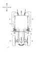
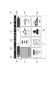
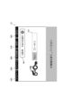
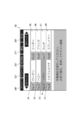
- FIG. 1 It is an external appearance perspective view of a tractor. It is the figure seen from the arrow X of FIG. It is the figure seen from the arrow Y of FIG. It is the figure seen from the arrow Z of FIG. It is a figure which shows the driver's seat of a tractor, and its circumference
- FIG. 1 shows a tractor 1.
- 2 is a view as seen from the arrow X in FIG. 1
- FIG. 3 is a view as seen from the arrow Y in FIG.
- FIG. 4 is a view seen from the arrow Z in FIG.
- the front-rear direction, the left-right direction, and the vertical direction of the tractor 1 are shown.
- the tractor 1 mainly includes a frame 11, an engine 12, a transmission 13, a front axle 14, and a rear axle 15. Further, the tractor 1 includes a cabin 16.
- the cabin 16 has a cockpit inside, and an accelerator pedal 162 and a shift lever 163 are arranged in addition to the driver's seat 161 (see FIG. 5).
- the frame 11 forms a skeleton at the front part of the tractor 1.
- the frame 11 constitutes the chassis of the tractor 1 together with the transmission 13 and the rear axle 15.
- the engine 12 described below is supported by the frame 11.
- the engine 12 converts thermal energy obtained by burning fuel into kinetic energy. That is, the engine 12 generates rotational power by burning fuel.
- the engine 12 is connected to an engine control device (not shown). When the operator operates the accelerator pedal 162 (see FIG. 5), the engine control device changes the operating state of the engine 12 according to the operation. Further, the engine 12 is provided with an exhaust purification device 12E.
- the exhaust purification device 12E oxidizes particulates, carbon monoxide, hydrocarbons, etc. contained in the exhaust.
- the transmission 13 transmits the rotational power of the engine 12 to the front axle 14 and the rear axle 15.
- the rotational power of the engine 12 is input to the transmission 13 via a coupling mechanism.
- the transmission 13 is provided with a continuously variable transmission (HST or HMT, not shown). When the operator operates the shift lever 163 (see FIG. 5), the continuously variable transmission changes the operating state of the transmission 13 according to the operation.
- HST continuously variable transmission
- the front axle 14 transmits the rotational power of the engine 12 to the front tire 141.
- the rotational power of the engine 12 is input to the front axle 14 via the transmission 13.
- the front axle 14 is provided with a steering device (not shown). When the operator operates the handle 164 (see FIG. 5), the steering device changes the steering angle of the front tire 141 according to the operation.
- the rear axle 15 transmits the rotational power of the engine 12 to the rear tire 151.
- the rotational power of the engine 12 is input to the rear axle 15 via the transmission 13.
- the rear axle 15 is provided with a PTO output device (not shown). When the operator operates the PTO switch 165 (see FIG. 5), the PTO output device transmits rotational power to the working machine to be pulled according to the operation.
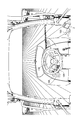
- FIG. 5 shows the driver's seat 161 and its surroundings.
- FIG. 6 shows the field of view of the operator.
- the cabin 16 has a cockpit inside, and an accelerator pedal 162 and a shift lever 163 are arranged in addition to the driver seat 161.
- a brake pedal 166, a clutch pedal 167, a reverser lever 168, a speed dial 169, an instrument panel 170, a control panel 171 and the like are disposed around the driver seat 161. The operator can operate the tractor 1 by operating the accelerator pedal 162 and the shift lever 163 while sitting on the driver's seat 161.
- the tractor 1 has a display 2 in the vicinity of the driver seat 161.
- the display 2 is disposed on the right front side of the driver seat 161 so that the operator can operate with the right hand.
- the information network of the tractor 1 will be briefly described, and the display 2 and the control system including the display 2 will be described in detail.
- FIG. 7 shows the information network of the tractor 1.
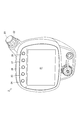
- FIG. 8 shows the display 2.
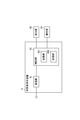
- FIG. 9 shows a control system for the tractor 1.
- This tractor 1 has an information network in various places so that the maximum performance can be achieved. Specifically, in addition to the engine 12, the transmission 13, the instrument panel 170, the control panel 171, and the display 2 constitute a controller area network (CAN) that can share information with each other.
- CAN controller area network
- the display 2 is disposed on the side console (see FIGS. 5 and 6).
- the display 2 includes a liquid crystal panel (display unit) 21, an encoder dial (operation unit) 22, an enter button (operation unit) 23, and five command buttons (operation units) 24 to 28. Is done.
- the liquid crystal panel 21 is provided at the front center of the display 2.
- the liquid crystal panel 21 can display a predetermined screen based on an instruction from the tractor control device 3.
- the liquid crystal panel 21 can display the opening screen S1 based on an instruction from the tractor control device 3 (see FIG. 13).
- the liquid crystal panel 21 can display other screens based on instructions from the tractor control device 3 (see FIGS. 14 to 24).
- the display unit is not limited to the liquid crystal panel 21, and a thin display panel such as an EL panel using an organic EL (electroluminescence) or an inorganic EL can also be used.
- the encoder dial 22 is provided on the upper right side of the display 2.
- the encoder dial 22 has a built-in rotary encoder, and when selecting an element (item) displayed on the liquid crystal panel 21, an operator's intention (selection operation) to scroll the tab or traverse the highlight display is selected. 3 can be transmitted.
- the encoder dial 22 can transmit the operator's intention to scroll the tab (see FIGS. 14 and 23) to the tractor control device 3 when selecting the displayed number or alphabetic character.
- the encoder dial 22 can transmit the operator's intention to traverse the highlight display to the tractor control device 3 when selecting the displayed icon (see FIGS. 15 to 23).
- the enter button 23 is provided integrally with the encoder dial 22.
- the enter button 23 is an operation button corresponding to the vertical movement of the encoder dial 22 and is operated by pressing the upper surface of the encoder dial 22.
- the enter button 23 may be a push button provided on the upper end surface of the encoder dial 22.
- the enter button 23 can transmit to the tractor control device 3 the operator's intention (decision operation) that one of the elements (items) displayed on the liquid crystal panel 21 has been determined.
- the enter button 23 can transmit to the tractor control device 3 the operator's intention to determine that one of the displayed numbers or English characters has been determined (see FIGS. 14 and 23).
- the enter button 23 can transmit the operator's intention to the effect that the one of the displayed icons has been determined to the tractor control device 3 (see FIGS. 15 to 23).
- the five command buttons 24 to 28 are operation buttons for determining an icon displayed at the upper end of the screen.
- the command buttons 24 to 28 are provided side by side in the upper part of the front surface of the display 2, and the command buttons 24 to 28 correspond to the icons immediately below displayed on the liquid crystal panel 21.
- the command buttons 24 to 28 can transmit to the tractor control device 3 an operator's intention that the icon immediately below has been determined. When any of the command buttons 24 to 28 is pressed, the tractor control device 3 executes a command corresponding to the icon.
- the icons and commands assigned to the command buttons 24 to 28 are different for each screen, and the icons and commands necessary for each screen are assigned.
- a command for instructing switching to the first home screen S3 icon is “HOME”
- a command for instructing switching to a shortcut screen screen arbitrarily set by the operator
- icon is “free 1”
- Free 2 a command for instructing determination of one element
- the icon is “decision”
- a command for instructing switching to the previous screen icon is “return”
- tab like the enter button 23
- a command the icon is an arrow indicating the direction for instructing the direction of scrolling or the direction of traversing the highlight display.
- a touch panel may be provided on the liquid crystal panel 21 as an operation unit.
- the encoder dial 22, the enter button 23, and the command buttons 24 to 28 can be omitted as appropriate.
- the tractor control device 3 controls the display 2, the remote monitoring terminal device 4, and other electrical systems of the tractor 1.
- the tractor control device 3 controls the display 2 in response to an instruction from the remote monitoring terminal device 4 or outputs an operation instruction from the display 2 to the remote monitoring terminal device 4.
- the remote monitoring terminal device 4 will be described after the outline of the remote monitoring system is described below.
- the tractor control device 3 and the remote monitoring terminal device 4 may be included in the display 2.
- FIG. 10 is a block diagram showing a schematic configuration of a remote monitoring system for remotely monitoring the tractor 1.
- the remote monitoring system 10 is provided in each of a remote monitoring device (management server) 5, one or more user terminal devices 6 connected to the remote monitoring device 5 via a network 7, and one or more tractors 1. And a remote monitoring terminal device 4 connected to the remote monitoring device 5 via a communication network 8.
- the remote monitoring device 5 is installed in a remote monitoring center located far from the tractor 1 and stores (accumulates) information and work plans regarding the operating state of the tractor 1 and daily work reports.
- the remote monitoring device 5 is connected to a user terminal device 6 such as a personal computer, a tablet computer, or a mobile terminal via a network such as a LAN (Local Area Network) or the Internet.
- the information stored in the remote monitoring device 5 is read by the remote monitoring terminal device 4 and used by the operator, and is read by the user terminal device 6 and is read by the owner of the tractor 1 or a user such as a dealer. It has come to be used.
- the remote monitoring terminal device 4 and the remote monitoring device 5 are connected to each other via a communication network 8 so that information can be transmitted and received between the remote monitoring terminal device 4 and the remote monitoring device 5. It is possible. Accordingly, the tractor 1 can be remotely monitored at the remote monitoring center, or the operator can read the information stored in the remote monitoring device 5 with the tractor 1 and check it.
- the communication network 8 may be a wired communication network, a wireless communication network, or a combination of a wired communication network and a wireless communication network.
- the communication network 8 is typically a public line network applied by a telecommunications carrier and can be a public line network in which terminals such as fixed telephones and mobile phones communicate with each other.
- the remote monitoring terminal device 4 includes a communication unit 41, a GPS (Global Positioning System) sensor 42, a position detection unit 43, a position information storage unit 44, and a control unit 45. .
- GPS Global Positioning System
- the communication unit 41 can communicate with the same communication protocol (communication protocol) as the communication unit of the remote monitoring device 5 in the remote monitoring center. Information transmitted and received during communication is converted by the communication unit 41 so as to follow the communication protocol. Then, the communication unit 41 transmits work progress information input by the operator, information on the operating state of the tractor 1 (operation information) acquired by the control unit 45, and information on daily work reports to the remote monitoring device 5. Further, the communication unit 41 receives a work plan from the remote monitoring device 5.
- communication protocol communication protocol
- the GPS sensor 42 is a sensor that receives radio waves from GPS satellites.
- the position detector 43 detects position information of the tractor 1 based on the radio wave received by the GPS sensor 42.
- the position detector 43 also detects speed information and azimuth information of the tractor 1. That is, the position information includes information on the longitude, latitude, speed, and direction of the tractor 1.
- the position information storage unit 44 includes a volatile memory such as a RAM (Random Access Memory), and temporarily stores the position information detected by the position detection unit 43. Information in the position information storage unit 44 is treated as operation information and transmitted to the remote monitoring device 5.
- the control unit 45 includes a processing unit 451 including a microcomputer such as a CPU (Central Processing Unit), and a storage unit 452 such as a ROM (Read Only Memory), RAM, a hard disk drive, and a flash memory.
- the control unit 45 controls the operation of various components by causing the processing unit 451 to read and execute a control program stored in advance in the ROM of the storage unit 452 on the RAM of the storage unit 452. Specifically, transmission / reception of information at the time of communication, various input / output controls, control of arithmetic processing, and the like are performed.
- the storage unit 452 stores information related to daily work reports.
- the information related to the daily work report includes operator information and work machine information.
- the operator information is information for identifying an operator. For example, an identifier such as an operator name, a number for each operator, a symbol for each operator, and the like can be used.
- the storage unit 452 stores the operator information of each of the plurality of operators, and stores the operator information most recently determined by the operator in an identifiable manner.
- the work machine information is information for identifying the work machine, and for example, an identifier such as a work machine name, a number for each work machine, or a symbol for each work machine can be used.
- the storage unit 452 stores the work machine information of each of the plurality of work machines, and stores the work machine information most recently determined by the operator in an identifiable manner.
- the processing unit 451 generates an operator selection image in which a plurality of operator information stored in the storage unit 452 is listed and one operator information can be selected and edited. In addition, the processing unit 451 generates a work machine selection image in which a plurality of work machine information stored in the storage unit 452 can be selected and the single work machine information can be selected and edited.
- the operator-selected image is displayed on the liquid crystal panel 21 via the tractor control device 3 by the output control of the control unit 45 (see FIG. 18).
- the work implement selection image is displayed on the liquid crystal panel 21 via the tractor control device 3 by the output control of the control unit 45 (see FIG. 20).
- the work plan received from the remote monitoring device 5 is displayed on the liquid crystal panel 21 via the tractor control device 3 by the output control of the control unit 45 (see FIG. 21).
- the operator can confirm the work plan managed by the remote monitoring device 5 with the tractor 1. Therefore, the operator does not need to go to the field after confirming the work plan with the user terminal device 6 in the office, and can save the labor of movement. Even if the work order is complicated, the work plan can be confirmed at any time, which leads to prevention of erroneous work.
- the input (instruction) by the operation unit is accepted through the tractor control device 3 by the input control of the control unit 45.
- the operator can select and determine his / her operator information and work machine information used this time. As described above, since the operator only selects and determines from pre-registered information, it can be easily operated.
- the determined operator information and work machine information are output to the communication unit 41 by the output control of the control unit 45 and transmitted from the communication unit 41 to the remote monitoring device 5.
- the operator can perform editing operations such as addition / change of operator information or work machine information. For example, editing can be performed by long pressing the enter button 23 in a state where operator information to be changed is selected.
- the determined operator information and work machine information can be transmitted to the remote monitoring device 5 together with the operation information. That is, it can be added to the operation information and transmitted. As a result, the number of transmissions can be reduced as compared with the case where operator information and work implement information are transmitted at a timing different from the transmission of operation information, and the communication load and communication charge can be reduced.
- the determined operator information and work implement information can be displayed on the opening screen S1 displayed on the liquid crystal panel 21 and / or the screen during work (not shown).
- the operator can check whether the operator information and work implement information are set correctly in addition to the operator information and work implement information selection and determination operations. Therefore, the operator is likely to notice when there is an error in the operator information or work implement information.
- the operator can input work progress information.
- the work progress information is information indicating which work has been completed and which work is being performed. For example, when an operation is completed, an input indicating that the operation is completed by erasing the corresponding operation plan, and an input indicating that the operation is completed up to the area by inputting text into the field area can do.
- the input work progress information is output to the communication unit 41 by output control of the control unit 45, and is transmitted from the communication unit 41 to the remote monitoring device 5.
- the remote monitoring terminal device 4 may be configured to edit the work plan on the schedule registration screen (see FIG. 23).
- FIG. 11 is a block diagram illustrating a schematic configuration of the remote monitoring device 5.
- the remote monitoring device 5 is, for example, a desktop personal computer, and includes a communication unit 51 and a control unit 52.
- a display unit 53 such as a liquid crystal panel and an operation unit 54 such as a keyboard are externally connected to the remote monitoring device 5.
- the display unit 53 and the operation unit 54 may have a configuration (for example, a notebook personal computer) included in the remote monitoring device 5.
- the communication unit 51 includes a first communication unit 511 and a second communication unit 512.
- the first communication unit 511 can communicate using the same communication protocol as the communication unit 41 of the remote monitoring terminal device 4. Information transmitted and received during communication is converted by the first communication unit 511 so as to follow the communication protocol.
- the first communication unit 511 receives the operation information of the tractor 1, information on the daily work report (operator information and work machine information) and work progress information from the remote monitoring terminal device 4, and sends the operator information to the remote monitoring terminal device 4. Information, update information of work implement information, update information related to control of the tractor 1 and work plan are transmitted.
- the second communication unit 512 is capable of communicating with the same communication protocol as the communication unit 61 of the user terminal device 6. Information transmitted / received at the time of communication is converted by the second communication unit 512 so as to follow the communication protocol. And the 2nd communication part 512 receives the update information of operator information and working machine information from the user terminal device 6, or transmits the work daily report and work progress information of the tractor 1 to the user terminal device 6. . The second communication unit 512 transmits and receives a work plan to and from the user terminal device 6.
- the control unit 52 includes a processing unit 521 including a microcomputer such as a CPU, and a storage unit 522 such as a ROM, a RAM, a hard disk drive, and a flash memory.
- the control unit 52 controls the operation of various components by causing the processing unit 521 to read out and execute a control program stored in advance in the ROM of the storage unit 522 onto the RAM of the storage unit 522. Specifically, transmission / reception of information at the time of communication, various input / output controls, control of arithmetic processing, and the like are performed.
- the processing unit 521 generates a daily work report based on the operation information of the tractor 1 received from the remote monitoring terminal device 4 and information on the daily work report, and stores the daily work report in the storage unit 522.
- a daily work report a work day, a work place, an operator name, a work machine name, work contents, an operation locus of the tractor 1 on a map, and the like are recorded.
- the processing unit 521 generates an operator edited image in which each operator information can be edited by listing a plurality of operator information stored in the storage unit 522. Further, the processing unit 521 generates a work machine edited image in which each work machine information can be edited by listing a plurality of work machine information stored in the storage unit 522.
- the daily work report stored in the storage unit 522 is displayed on the display unit 53 by the output control of the control unit 52.
- the input (instruction) by the operation unit 54 is accepted by the input control of the control unit 52.
- the daily work report stored in the storage unit 522 is transmitted to the user terminal device 6 by the output control of the control unit 52.
- the daily work report may also be transmitted to the remote monitoring terminal device 4.
- the daily work report is transmitted when there is a request from the user terminal device 6 or the remote monitoring terminal device 4.
- the daily work report can be viewed on the web at the user terminal device 6 or the remote monitoring terminal device 4.
- the operator edit image and the work machine edit image are transmitted to the user terminal device 6 by the output control of the control unit 52.
- the operator edited image and the work machine edited image are transmitted when there is a request from the user terminal device 6.
- editing such as addition / change of an operator name or work machine name used as operator information or work machine information can be performed on the web.
- the operator edit image and the work machine edit image are transmitted to the remote monitoring terminal device 4 by the output control of the control unit 52 so that the tractor 1 side can edit the operator name, the work machine name, and the like. Also good.
- the storage unit 522 stores work plans and work progress information.
- the screen for registering the work plan can be input for each item (see FIG. 22).
- the work plan item includes the work date and time. Thereby, the work plan can be managed on the calendar.
- the work plan items may include other items such as work contents, operator, work place, work order, work machine to be mounted, work frequency, and setting of the tractor 1. This improves the convenience of the work plan.
- a desired date and time can be specified on the schedule registration screen (see FIG. 23), and can be confirmed on the calendar screen (see FIG. 21).
- the work content refers to specific work such as farm maintenance work.
- the operator can grasp what kind of work should be done by confirming the work content.
- the operator is the name of the operator who works.
- the operator can confirm that the operation is performed by confirming that the operator name is written.
- the work place is a place in the field, and for example, a section number can be used.
- the operator can grasp which field to work by confirming the work place.
- the order of work refers to the order of fields to be worked, and for example, the numbers of sections can be arranged in the order of work. The operator can work efficiently by working in the order of work.
- the working machine to be mounted is the name of the working machine to be attached to the tractor 1, for example, rotary, harrow, plow or the like.
- the operator can grasp which work machine should be used by confirming the name of the work machine to be mounted.
- the work frequency is the frequency of repeating the same work, and can be, for example, no repeat, repeat every week, repeat every month, repeat every year, or the like.
- the setting of the tractor 1 is a setting value that can be customized by the operator for the operation of the tractor 1.
- the set value for example, a set value that sets whether the start feeling is moderately accelerated or rapidly accelerated, and the horizontal control of the work machine operates gently or agilely with respect to the inclination of the tractor 1.
- the processing unit 521 stores the input work plan received from the user terminal device 6 in the storage unit 522.
- the processing unit 521 causes the storage unit 522 to store work progress information received from the remote monitoring terminal device 4.
- the output control of the control unit 52 By the output control of the control unit 52, the work plan stored in the storage unit 522 and the progress information of the work received from the remote monitoring terminal device 4 are displayed on the display unit 53.
- the input (instruction) by the operation unit 54 is accepted by the input control of the control unit 52.
- the screen of the work plan created by the web designer or the like can be stored in the storage unit 522.
- the work plan is transmitted to the remote monitoring terminal device 4, and the work plan and work progress information are transmitted to the user terminal device 6.
- the work plan is transmitted when there is a request from the user terminal device 6 or the remote monitoring terminal device 4.
- Work progress information is transmitted to the user terminal device 6 in real time when received from the remote monitoring terminal device 4.
- the edited work plan is transmitted to the user terminal device 6 in real time.
- the work plan can be viewed on the web in the remote monitoring terminal device 4, and the progress information of the work can be input on the web. Then, work progress information is transmitted to the user terminal device 6 in real time via the remote monitoring device 5. Thereby, the progress information of the work can be viewed on the web in the user terminal device 6, and the editing such as addition / change of the work plan can be performed on the web.
- the edited work plan is transmitted to the remote monitoring terminal device 4 in real time via the remote monitoring device 5.
- the edited work plan can be viewed on the web in the remote monitoring terminal device 4, so that the operator can immediately cope with a change in the work plan.
- FIG. 12 is a block diagram illustrating a schematic configuration of the user terminal device 6.
- the user terminal device 6 is, for example, a desktop personal computer, and includes a communication unit 61 and a control unit 62. Further, a display unit 63 such as a liquid crystal panel and an operation unit 64 such as a keyboard are externally connected to the user terminal device 6. Note that the display unit 63 and the operation unit 64 may be configured to be included in the user terminal device 6 (for example, a notebook personal computer).
- the communication unit 61 can communicate with the communication unit 51 of the remote monitoring device 5 using the same communication protocol. Information transmitted and received at the time of communication is converted by the communication unit so as to follow the communication protocol.
- the communication unit 61 receives the daily work report of the tractor 1, the operator edited image, the work machine edited image, and the work progress information from the remote monitoring device 5, and updates the operator information and work machine information to the remote monitoring device 5. Or send.
- the communication unit 61 transmits and receives a work plan to and from the remote monitoring device 5.
- the control unit 62 includes a processing unit 621 composed of a microcomputer such as a CPU, and a storage unit 622 such as a ROM, RAM, hard disk drive, and flash memory.
- the control unit 62 controls the operation of various components by causing the processing unit 621 to read and execute a control program stored in advance in the ROM of the storage unit 622 onto the RAM of the storage unit 622. Specifically, transmission / reception of information at the time of communication, various input / output controls, control of arithmetic processing, and the like are performed.
- the daily work report, work plan, and work progress information of the tractor 1 received from the remote monitoring device 5 is displayed on the display unit 63. Also, input (editing) from the operation unit 64 to the remarks column of the daily work report and input to each item of the work plan (editing) are accepted by the control of the control unit 62. Thereby, the user (the manager of the field) can access the remote monitoring device 5 to check and edit the daily work report. Further, the user can access the remote monitoring device 5 and edit the work plan on the schedule registration screen (see FIG. 23), for example. It is also possible to change the work plan after confirming the progress information of the work sent in real time.
- the operator edit image or work implement edit image received from the remote monitoring device 5 is displayed on the display unit 63 by the output control of the control unit 62.
- an editing operation such as addition / change of operator information or work implement information is accepted from the operation unit 64 by input control of the control unit 62.
- the user accesses the remote monitoring device 5 and stores it as operator information or work implement information when an operator in charge of the tractor 1 or a work implement attachable to the tractor 1 is added or changed. You can edit the operator name and work equipment name.
- the operator can determine and operate the operator information and work machine information with the tractor 1, so that the operator or the like manually inputs the operator name and work machine name later in the daily work report. There is no need to do it. Therefore, it is possible to improve the convenience by eliminating the trouble of the operator or the like and forgetting to input.
- the opening screen S1 is displayed on the display 2 (see FIG. 13).
- a symbol mark Sm is displayed near the center.
- the symbol mark Sm is a design symbolizing the supplier manufacturer.
- the symbol mark Sm floats on a black background image and gives a strong impression to the operator.
- the lock release screen S2 is displayed on the display 2 (see FIG. 14).
- the unlock screen S2 four scroll boxes Sb1 to Sb4 for inputting the password are displayed in a horizontal row. Any one of the scroll boxes Sb1 to Sb4 is highlighted (refer to part H in the figure).
- the scroll boxes Sb1 to Sb4 can scroll numbers from 0 to 9 or English letters from A to F vertically.
- buttons 251, 261, 271, and 281 corresponding to the command buttons 25 to 28 are displayed at the upper end.
- a dialog box Db1 in which the operator name is written and a dialog box Db2 in which the work machine name is written are displayed.
- the operator can confirm whether the operator name and the work machine name are correctly set in these dialog boxes Db1 and Db2.
- the description contents of the dialog boxes Db1 and Db2 are wrong, they can be changed by an operator selection screen S6 or a work machine selection screen S8 and S9 described later.
- the operator can make a decision by turning the encoder dial 22 to scroll through numbers or letters and pressing the enter button 23. Further, in the unlock screen S2, it is also possible to select by scrolling a number or alphabet by pressing the command buttons 25 and 26 and pressing the command button 27. The decision can also be canceled by pressing the command button 28. If the password is wrong, a message to that effect is displayed.
- the first home screen S3 is displayed on the display 2 (see FIG. 15).
- icons Ia1 to Ia10 for selecting a menu or a page are displayed. Any one of the selected icons Ia1 to Ia10 is highlighted (refer to part H in the figure).
- the highlight display is traversed according to the rotation of the encoder dial 22. Icons that cannot be selected are grayed out (see part G in the figure).
- icons 242, 252, 262, 272, and 282 corresponding to the command buttons 24 to 28 are displayed at the upper end.
- the registration method to the “free 1” icon 242 or the “free 2” icon 252 will be briefly described by taking the registration to “free 1” as an example.
- the screen changes to a registration screen (not shown).
- a desired icon for example, “OFF” icon
- pressing the enter button 23 the icon is registered in the “free 1” icon 242.
- the icon is displayed instead of “1”.
- the operator can select the desired icons Ia1 to Ia10 by turning the encoder dial 22, and press the enter button 23 or the command button 27 to determine.
- the icon Ia10 marked “next page” is selected and determined.
- the second home screen S4 is displayed on the display 2 (see FIG. 16).
- icons Ib1 to Ib10 for selecting a menu or a page are displayed. Any one of the selected icons Ib1 to Ib10 is highlighted (refer to part H in the figure). The highlight display is traversed according to the rotation of the encoder dial 22.
- icons 243, 253, 263, 273, and 283 corresponding to the command buttons 24 to 28 are displayed at the upper end.
- the operator can select the desired icons Ib1 to Ib10 by turning the encoder dial 22, and press the enter button 23 or the command button 27 to determine.
- the icon Ib8 marked “user” or the icon Ib9 marked “work” is selected and determined.
- an operator display screen S5 is displayed on the display 2 (see FIG. 17). On the operator display screen S5, selectable icons Ic1 and Ic2 are displayed.
- the dialog box Db1 with the operator name is displayed on the unlock screen S2.
- the icon Ic2 indicates the currently set operator name (MURATA in FIG. 17). A number (No. 1 in FIG. 17) corresponding to the currently set operator name is displayed on the left of the icon Ic2, and an operation guide is displayed below the icon Ic2.
- icons 244, 254, 264, 274 and 284 corresponding to the command buttons 24 to 28 are displayed at the upper end.
- the operator can determine by selecting the desired icons Ic1 and Ic2 by turning the encoder dial 22 and pressing the enter button 23 or the command button 27.
- the icon Ic2 is selected and determined.
- an operator selection screen S6 is displayed on the display 2 (see FIG. 18).
- an operator selection image including icons Id1 to Id8 for selecting an operator name is displayed.
- operator names are registered in the icons Id1 to Id3, and the icons Id4 to Id8 are not registered. Any one of the selected icons Id1 to Id8 is highlighted (refer to part H in the figure). The highlight display is traversed according to the rotation of the encoder dial 22.
- the numbers corresponding to the icons Id1 to Id8 are displayed on the left side of the icons Id1 to Id8, and operation guidance is displayed below the icons Id1 to Id8.
- icons 245, 255, 265, 275, and 285 corresponding to the command buttons 24 to 28 are displayed at the upper end.
- the operator can determine by selecting the desired icons Id1 to Id8 by turning the encoder dial 22, and pressing the enter button 23 or the command button 27 for a short time (for example, less than 3 seconds).
- the determined operator information of the icons Id1 to Id8 is stored in the storage unit 452, transmitted to the remote monitoring device 5, and reflected in the daily work report or the like.
- the operator selects desired icons Id1 to Id8 by turning the encoder dial 22, and can edit by pressing and holding the enter button 23 or the command button 27 (for example, 3 seconds or more). Can be.
- the edited operator name can be stored as operator information by pressing the enter button 23 or the command button 27 for a short time.
- the work machine display screen S7 is displayed on the display 2 (see FIG. 19). On the work machine display screen S7, selectable icons Ie1 and Ie2 are displayed.
- the operator can select the desired icons Ie1 and Ie2 by turning the encoder dial 22, and press the enter button 23 or the command button 27 to determine.
- the icon Ie2 is selected and determined.
- the work machine selection screen S8 is displayed on the display 2 (see FIG. 20).
- a work machine selection image including icons If1 to If8 for selecting a work machine name (work machine information) is displayed on the display 2 (see FIG. 20).
- Any one of the selected icons If1 to If8 is highlighted (refer to part H in the figure).
- the highlight display is traversed according to the rotation of the encoder dial 22.
- the operator can select a desired icon If1 to If8 by turning the encoder dial 22, and press the enter button 23 or the command button 27 for a short time.
- the determined working machine information of the icons If1 to If8 is stored in the storage unit 452, transmitted to the remote monitoring device 5, and reflected in the daily work report or the like.
- the operator can edit by selecting the desired icons If1 to If8 by turning the encoder dial 22, and pressing and holding the enter button 23 or the command button 27 (for example, 3 seconds or more). Can be in a state.
- the edited work machine name can be stored as work machine information by pressing the enter button 23 or the command button 27 for a short time.
- the display 2 displays a calendar screen S9 that is one screen of the work plan (see FIG. 21).
- the calendar screen S9 is acquired from the remote monitoring device 5.
- today's date January 15, 2014 in FIG. 21
- the date when the work plan is registered January 20, 2014 in FIG. 21
- 21st, 28th, 30th are displayed in light blue.
- a dialog box Db5 in which the work schedule for today is written is displayed.
- the content entered in the dialog box Db5 reflects the content entered in the input field of the schedule registration screen S11 to be described later.
- “Hojo Seigo A1-A20” is written in the dialog box Db5. This indicates that the work content to be performed today by the tractor 1 is the field maintenance work, the work place is from the section A1 to the section A20 of the field, and the order of the work is the order of the sections A1, A2,... A20. ing.
- selectable icons Ig1 to Ig4 are displayed. One of the selected icons Ig1 to Ig4 is highlighted. The highlight display is traversed according to the rotation of the encoder dial 22.
- icons 248, 258, 268, 278, and 288 corresponding to the command buttons 24 to 28 are displayed at the upper end.
- the operator can select a desired icon Ig1 to Ig4 by turning the encoder dial 22, and press the enter button 23 or the command button 27 to make a determination.
- Icon Ig1 is an icon for displaying the calendar of the previous month of the displayed month
- icon Ig2 is an icon for displaying the calendar of the next month of the displayed month.
- the icon Ig3 is marked with “schedule confirmation”. When this icon Ig3 is selected and determined, a schedule confirmation screen S10 is displayed on the display 2.
- the icon Ig4 is marked with “schedule registration”, and when this icon Ig4 is selected and determined, a schedule registration screen S11 is displayed on the display 2.
- a schedule confirmation screen S10 which is one screen of the work plan is displayed on the display 2 (see FIG. 22).
- the schedule confirmation screen S10 is acquired from the remote monitoring device 5.
- selectable icons Ih1 to Ih6 are displayed. Any one of the selected icons Ih1 to Ih6 is highlighted (refer to part H in the figure). The highlight display is traversed according to the rotation of the encoder dial 22.
- icons 249, 259, 269, 279, and 289 corresponding to the command buttons 24 to 28 are displayed at the upper end.
- the icon Ih1 is an icon for displaying the previous page (calendar screen S9), and the icon Ih6 is an icon for displaying the next page (continuation of the schedule confirmation screen S10 (not shown)).
- Icons Ih2 to Ih5 indicate the numbers of the respective work plans, and corresponding work dates and times and work contents are written on the right side of the icons Ih2 to Ih5. With this schedule confirmation screen S10, the operator can confirm today and future work plans.
- the operator selects the work plan icons Ih2 to Ih5 by turning the encoder dial 22, and presses the enter button 23 or the command button 27 for a short time (for example, less than 3 seconds) to thereby display work progress information. Can be entered. For example, when the icon is determined to be the icon Ih2, it is possible to indicate to which section the work has been completed (for example, completion up to A3), following the description of “Hojo Sebisyo A1-A20”.
- the operator selects the work plan icons Ih2 to Ih5 by turning the encoder dial 22, and presses the enter button 23 or the command button 27 for a long time (for example, 3 seconds or more), thereby making the work plan.
- erasure means that work completion information has been input as work progress information.
- the progress information of the work input on the schedule confirmation screen S10 is stored in the storage unit 452 and transmitted to the user terminal device 6 via the remote monitoring device 5 in real time.
- the work progress information is confirmed on the user terminal device 6 side by the user (a farm manager). Then, the work plan is changed as necessary.
- the schedule registration screen S11 which is one screen of the work plan, is displayed on the display 2 (see FIG. 23).
- the schedule registration screen S11 is acquired from the remote monitoring device 5.
- three scroll boxes Sb5 to Sb7 for inputting work date and time are displayed on the schedule registration screen S11.
- the scroll box Sb5 can scroll numbers from 00 to 99, the scroll box Sb6 from 00 to 12, and the scroll box Sb7 from 00 to 31.
- the operator can determine by scrolling through the numbers by turning the encoder dial 22 and pressing the enter button 23 or the command button 27.
- selectable icons Ii1 to Ii6 are displayed.
- the icons Ii1 to Ii6 are highlighted so that it can be seen that they are selected.
- the highlight display is traversed according to the rotation of the encoder dial 22.
- icons 24A, 25A, 26A, 27A, and 28A corresponding to the command buttons 24 to 28 are displayed at the upper end.
- the icons Ii1 to Ii4 are used to set the repetition frequency of the work.
- the check mark is displayed by pressing the enter button 23 or the command button 27. Is displayed (in FIG. 23, the icon Ii1 indicates a state in which a check mark is displayed), work plans having the same contents are registered at the same frequency.
- the icon Ii5 is an input field.
- the enter button 23 or the command button 27 is pressed while the icon Ii5 is selected (highlighted), the work content, the operator, the work place, the work order, and the work to be mounted. You can enter the machine. As a result, the operator can edit the work plan by himself / herself.
- the icon Ii6 is an icon for registering a work plan, and is displayed on the schedule registration screen S11 by pressing the enter button 23 or the command button 27 while the icon Ii5 is selected (highlighted). The work plan is registered with the contents.
- the today's schedule screen S12 (see FIG. 24) on which today's work schedule is recorded may be displayed as appropriate. For example, it can be inserted between the unlock screen S2 and the first home screen S3.
- the operator information used for the above-described operator selection image and the work machine information used for the work machine selection image are stored in the remote monitoring device 5 and transmitted to the remote monitoring terminal device 4 when the information is updated. Also good. Thereby, the remote monitoring terminal device 4 can always use the latest information.
- the operator information used for the operator selection image and the work machine information used for the work machine selection image are not stored on the tractor 1 side (remote monitoring terminal device 4 or the like), but are stored in the remote monitoring device 5, and the operator selection screen S6 or The remote monitoring terminal device 4 may acquire from the remote monitoring device 5 as appropriate when the work implement selection screens S8 and S9 are displayed. Thereby, the remote monitoring terminal device 4 can always use the latest information.
- Various settings of the tractor 1 can be stored in the tractor control device 3 or the remote monitoring device 5 for each operator information, and when any operator information is selected and determined in the tractor 1, In conjunction with this, the tractor 1 may read and apply the setting corresponding to the determined operator information. As a result, the operator does not need to set his / her favorite setting every time the use of the tractor 1 is started, and can immediately start work. Further, instead of the setting according to the operator's preference, the setting at the previous use may be automatically saved for each operator information, and the setting at the previous use may be read and applied at the next use.
- the daily work report has been described as an example of the usage form of the operator information and the work machine information.
- the present invention is not limited to this, and can be used for, for example, a work weekly report or a work monthly report.
- the remote monitoring system 10 may include a mobile terminal device that acquires and outputs a work plan from the remote monitoring device 5.
- a mobile terminal device that acquires and outputs a work plan from the remote monitoring device 5.
- the operator can check the work plan anywhere, such as while moving to the tractor 1, and is highly convenient. Moreover, you may enable it to input the progress information and work plan of work from this portable terminal device. This further improves convenience.
- a portable terminal device capable of inputting a work plan can also be used by a user (a farm manager).
- the present invention can be used in a remote monitoring system for remotely monitoring a work vehicle for agricultural work or civil engineering work.
Landscapes
- Engineering & Computer Science (AREA)
- Business, Economics & Management (AREA)
- Tourism & Hospitality (AREA)
- General Physics & Mathematics (AREA)
- Physics & Mathematics (AREA)
- General Health & Medical Sciences (AREA)
- Health & Medical Sciences (AREA)
- Economics (AREA)
- Mechanical Engineering (AREA)
- Human Resources & Organizations (AREA)
- Marketing (AREA)
- Primary Health Care (AREA)
- Strategic Management (AREA)
- General Business, Economics & Management (AREA)
- Theoretical Computer Science (AREA)
- Computer Networks & Wireless Communication (AREA)
- Lifting Devices For Agricultural Implements (AREA)
Abstract
作業日報に手動でオペレータ名を入力する必要のない、利便性の高い作業車両を提供することを目的とする。そのため、作業車両であるトラクタ(1)は、オペレータを識別するための複数のオペレータ情報を選択可能に表示する液晶パネル(21)と、液晶パネル(21)に表示されたオペレータ情報を選択及び決定操作するためのエンコーダダイヤル(22)、エンターボタン(23)及びコマンドボタン(24~28)と、決定されたオペレータ情報を遠隔監視装置へ送信する遠隔監視端末装置(4)とを備える。
Description
本発明は、遠隔監視端末装置を備えた作業車両、該作業車両と通信する管理サーバ、該作業車両と該管理サーバとを含む遠隔監視システムに関する。
従来から農作業用や土木作業用の作業車両に備えられる遠隔監視端末装置と、遠隔監視センターに設けられる管理サーバとの間で通信を行って、作業車両を監視する遠隔監視システムが知られている(特許文献1参照)。
このような遠隔監視システムによれば様々なサービスを提供でき、例えば、作業車両の故障内容を監視したり、作業時間、走行距離、燃料消費量などの稼働情報をウェブを通じて提供したり、稼働情報に基づく最適なメンテナンス計画を提案したり、作業日報をウェブ上に自動的に作成したり、作業車両の無断使用を監視したりすることができる。作業日報では地図上で作業車両の稼働軌跡を確認することもでき、作業の管理や改善に利用できる。
しかしながら、オペレータ名や作業機については自動で判別できないため、オペレータ等が作業日報に後から手動で入力しなければならず、手間が掛かり、入力し忘れるおそれもあった。
本発明は、作業日報に手動でオペレータ名を入力する必要のない、利便性の高い作業車両を提供することを目的とする。また、その作業車両と通信可能な管理サーバを提供することも目的とする。また、上記作業車両及び管理サーバを含む遠隔監視システムを提供することも目的とする。
ところで、営農集団では作業日時や作業内容などが記された作業計画を立て、オペレータはその作業計画に従って日々の作業を行っている。作業計画は通常、事務所の端末装置等に格納されている。
このような状況下では、オペレータは事務所の端末装置等で作業計画を確認してから圃場に向かう必要があり、手間が掛かっていた。また、作業手順が複雑な場合等にはオペレータが誤った作業を行うおそれもあった。
本発明は、管理サーバで管理される作業計画を作業車両で確認することができる遠隔監視システムを提供することを目的とする。また、その遠隔監視システムの管理サーバを提供することも目的とする。
作業車両は、オペレータを識別するための複数のオペレータ情報を選択可能に表示する表示部と、前記表示部に表示された前記オペレータ情報を選択及び決定操作するための操作部と、決定された前記オペレータ情報を管理サーバへ送信する遠隔監視端末装置とを備える。
上記の作業車両において、前記遠隔監視端末装置は、本作業車両の稼働状況を示す稼働情報とともに、決定された前記オペレータ情報を前記管理サーバへ送信するようにしてもよい。
また上記の作業車両において、前記表示部は、オープニング画面及び/又は作業中の画面に、直近に決定された前記オペレータ情報を表示するようにしてもよい。
また上記の作業車両において、前記表示部は、作業機を識別するための複数の作業機情報を選択可能に表示し、前記操作部は、前記表示部に表示された前記作業機情報を選択及び決定操作でき、前記遠隔監視端末装置は、決定された前記作業機情報を前記管理サーバへ送信するようにしてもよい。
また上記の作業車両において、前記遠隔監視端末装置は、本作業車両の稼働状況を示す稼働情報とともに、決定された前記作業機情報を管理サーバへ送信するようにしてもよい。
また上記の作業車両において、前記表示部は、オープニング画面及び/又は作業中の画面に、直近に決定された前記作業機情報を表示するようにしてもよい。
遠隔監視システムは、項目別に入力可能な作業計画を格納する管理サーバと、前記管理サーバから前記作業計画を取得して出力し、各項目の入力を受け付ける利用者端末装置と、作業車両に備えられ、前記管理サーバから前記作業計画を取得して出力する遠隔監視端末装置とを含む。
上記の遠隔監視システムにおいて、前記作業計画には、作業日時が含まれてもよい。
また上記の遠隔監視システムにおいて、前記作業計画には、作業内容、オペレータ、作業場所、作業の順序、装着する作業機、作業頻度、作業車両の設定のうち、少なくとも1つが含まれてもよい。
また上記の遠隔監視システムにおいて、前記遠隔監視端末装置は作業の進捗情報の入力を受け付け、前記管理サーバは前記遠隔監視端末装置から前記進捗情報を取得し、前記利用者端末装置は前記管理サーバから前記進捗情報を取得して出力するようにしてもよい。
また上記の遠隔監視システムにおいて、前記管理サーバから前記作業計画を取得して出力する携帯端末装置を含むようにしてもよい。
管理サーバは、利用者端末装置及び作業車両に備えられる遠隔監視端末装置と通信する管理サーバであって、項目別に入力可能な作業計画を格納し、前記利用者端末装置によって各項目が入力された前記作業計画を取得し、前記遠隔監視端末装置へ前記作業計画を送信する。
上記の作業車両によれば、オペレータは予め登録された複数のオペレータ情報(オペレータ名等)から自身のオペレータ情報を選択、決定操作するだけなので、簡単に操作することができる。そして、決定されたオペレータ情報は自動的に管理サーバへ送信されるので、管理サーバ側で作業日報に反映させることができ、オペレータ等が後から手動で作業日報にオペレータ名を入力する必要がなくなる。よって、オペレータ等の手間や入力し忘れをなくし、利便性を向上させることができる。
また上記の作業車両によれば、稼働情報とともに、決定されたオペレータ情報を管理サーバへ送信することにより、オペレータ情報を稼働情報の送信とは別のタイミングで送信する場合よりも送信回数を減らすことができ、通信負荷や通信料金を軽減できる。
また上記の作業車両によれば、オープニング画面、及び/又は作業中の画面に、直近に決定されたオペレータ情報を表示することにより、オペレータ情報の選択、決定操作時以外にも、オペレータはオペレータ情報が正しく設定されているかを確認できる。よって、オペレータはオペレータ情報に間違いがある場合に気づきやすい。
また上記の作業車両によれば、オペレータは予め登録された複数の作業機情報(作業機名等)から今回使用する作業機情報を選択、決定操作するだけなので、簡単に操作することができる。そして、決定された作業機情報は自動的に管理サーバへ送信されるので、管理サーバ側で作業日報に反映させることができ、オペレータ等が後から手動で作業日報に作業機名を入力する必要がなくなる。よって、オペレータ等の手間や入力し忘れをなくし、利便性を向上させることができる。
また上記の作業車両によれば、稼働情報とともに、決定された作業機情報を管理サーバへ送信することにより、作業機情報を稼働情報の送信とは別のタイミングで送信する場合よりも送信回数を減らすことができ、通信負荷や通信料金を軽減できる。
また上記の作業車両によれば、オープニング画面及び/又は作業中の画面に、直近に決定された作業機情報を表示することにより、作業機情報の選択、決定操作時以外にも、オペレータは作業機情報が正しく設定されているかを確認できる。よって、オペレータは作業機情報に間違いがある場合に気づきやすい。
上記の遠隔監視システムによれば、管理サーバで管理される作業計画を作業車両側の遠隔監視端末装置で確認することができる。よって、オペレータは事務所の利用者端末装置で作業計画を確認してから作業場所に向かう必要がなく、移動の手間を省くことができる。また、作業順序が複雑な場合等であっても、いつでも作業計画を確認できるので、誤った作業の防止に繋がる。
また上記の遠隔監視システムによれば、作業計画に作業日時が含まれることにより、カレンダー上で作業計画を管理することができる。
また上記の遠隔監視システムによれば、作業計画に、作業内容、オペレータ、作業場所、作業の順序、装着する作業機、作業頻度、作業車両の設定などが含まれることにより、作業計画の利便性が向上する。
また上記の遠隔監視システムによれば、作業の進捗情報を用いることにより、利用者端末装置側で作業の進捗情報を見て作業計画の追加・変更等の編集を行うことができ、遠隔監視端末装置側で編集された作業計画を見て、作業を変更できる。
また上記の遠隔監視システムによれば、作業計画を取得して出力する携帯端末装置を用いることにより、オペレータは作業車両への移動中など、どこででも作業計画を確認することができ、利便性が高い。
本発明の技術的思想は、あらゆる作業車両に適用することが可能である。以下では、代表的な作業車両であるトラクタを用いて説明する。
<トラクタ>
図1は、トラクタ1を示している。図2は、図1の矢印Xから見た図であり、図3は、図1の矢印Yから見た図である。また、図4は、図1の矢印Zから見た図である。なお、図中には、トラクタ1の前後方向、左右方向及び上下方向を表す。
図1は、トラクタ1を示している。図2は、図1の矢印Xから見た図であり、図3は、図1の矢印Yから見た図である。また、図4は、図1の矢印Zから見た図である。なお、図中には、トラクタ1の前後方向、左右方向及び上下方向を表す。
トラクタ1は、主に、フレーム11と、エンジン12と、トランスミッション13と、フロントアクスル14と、リヤアクスル15と、で構成されている。また、トラクタ1は、キャビン16を備えている。キャビン16は、その内側が操縦室になっており、運転座席161のほか、アクセルペダル162やシフトレバー163などが配置されている(図5参照)。
フレーム11は、トラクタ1の前部における骨格をなす。フレーム11は、トランスミッション13やリヤアクスル15とともにトラクタ1のシャシを構成する。以下に説明するエンジン12は、フレーム11によって支持される。
エンジン12は、燃料を燃焼させて得た熱エネルギーを運動エネルギーに変換する。つまり、エンジン12は、燃料を燃やすことによって回転動力を生み出す。なお、エンジン12には、エンジン制御装置が接続されている(図示せず)。エンジン制御装置は、オペレータがアクセルペダル162(図5参照)を操作すると、その操作に応じてエンジン12の運転状態を変更する。また、エンジン12には、排気浄化装置12Eが備えられている。排気浄化装置12Eは、排気に含まれる微粒子や一酸化炭素、炭化水素などを酸化させる。
トランスミッション13は、エンジン12の回転動力をフロントアクスル14やリヤアクスル15に伝達する。トランスミッション13には、連結機構を介してエンジン12の回転動力が入力される。なお、トランスミッション13には、無段変速装置(HST若しくはHMT、図示せず)が備えられている。無段変速装置は、オペレータがシフトレバー163(図5参照)を操作すると、その操作に応じてトランスミッション13の作動状態を変更する。
フロントアクスル14は、エンジン12の回転動力をフロントタイヤ141に伝達する。フロントアクスル14には、トランスミッション13を介してエンジン12の回転動力が入力される。なお、フロントアクスル14には、操舵装置が並設されている(図示せず)。操舵装置は、オペレータがハンドル164(図5参照)を操作すると、その操作に応じてフロントタイヤ141の舵角を変更する。
リヤアクスル15は、エンジン12の回転動力をリヤタイヤ151に伝達する。リヤアクスル15には、トランスミッション13を介してエンジン12の回転動力が入力される。なお、リヤアクスル15には、PTO出力装置(図示せず)が設けられている。PTO出力装置は、オペレータがPTOスイッチ165(図5参照)を操作すると、その操作に応じて牽引する作業機に回転動力を伝達する。
次に、トラクタ1の操縦室について説明する。
図5は、運転座席161とその周囲を示している。また、図6は、オペレータの視界を示している。
上述したように、キャビン16は、その内側が操縦室になっており、運転座席161のほか、アクセルペダル162やシフトレバー163などが配置されている。また、運転座席161の周囲には、ブレーキペダル166やクラッチペダル167、リバーサレバー168、スピードダイヤル169、インストルメントパネル170、コントロールパネル171などが配置されている。オペレータは、運転座席161に座った状態でアクセルペダル162やシフトレバー163などを操作し、トラクタ1を操縦することができる。
更に、本トラクタ1においては、運転座席161の近傍にディスプレイ2を具備している。ディスプレイ2は、オペレータが右手で操作できるよう、運転座席161の右前側に配置されている。以下に、トラクタ1の情報ネットワークについて簡単に説明するとともに、ディスプレイ2及び該ディスプレイ2を含む制御システムについて詳しく説明する。
図7は、トラクタ1の情報ネットワークを示している。図8は、ディスプレイ2を示している。図9は、本トラクタ1の制御システムを示している。
本トラクタ1は、最大限の性能を発揮できるよう、各所に情報ネットワークが張り巡らされている。具体的には、エンジン12のほか、トランスミッション13、インストルメントパネル170、コントロールパネル171、ディスプレイ2が互いに情報を共有できるコントローラ・エリア・ネットワーク(CAN)を構成している。
本トラクタ1において、ディスプレイ2は、サイドコンソールの上に配置されている(図5、図6参照)。ディスプレイ2は、液晶パネル(表示部)21と、エンコーダダイヤル(操作部)22と、エンターボタン(操作部)23と、5つのコマンドボタン(操作部)24~28とが一体に設けられて構成される。
液晶パネル21は、ディスプレイ2の前面中央に設けられている。液晶パネル21は、トラクタ制御装置3からの指示に基づいて所定の画面を表示できる。例えば、液晶パネル21は、トラクタ制御装置3からの指示に基づいてオープニング画面S1を表示できる(図13参照)。また、液晶パネル21は、トラクタ制御装置3からの指示に基づいてその他の画面を表示できる(図14から図24参照)。なお、表示部は液晶パネル21に限定されることはなく、有機EL(electroluminescence)又は無機ELを用いたELパネル等の薄型表示パネルなどを用いることもできる。
エンコーダダイヤル22は、ディスプレイ2の上面右側に設けられている。エンコーダダイヤル22は、ロータリエンコーダを内蔵し、液晶パネル21に表示された要素(項目)の選択に際して、タブをスクロールさせる若しくはハイライト表示をトラバースさせる旨のオペレータの意思(選択操作)をトラクタ制御装置3へ伝達できる。例えば、エンコーダダイヤル22は、表示された数字や英文字の選択に際して、タブをスクロール(図14、図23参照)させる旨のオペレータの意思をトラクタ制御装置3へ伝達できる。また、エンコーダダイヤル22は、表示されたアイコンの選択に際して、ハイライト表示をトラバースさせる旨のオペレータの意思をトラクタ制御装置3へ伝達できる(図15から図23参照)。
エンターボタン23は、エンコーダダイヤル22と一体的に設けられている。エンターボタン23は、エンコーダダイヤル22の上下動に対応した操作ボタンであり、エンコーダダイヤル22の上面が押されることによって操作される。なお、エンターボタン23は、エンコーダダイヤル22の上端面に設けた押しボタンであってもよい。
エンターボタン23は、液晶パネル21に表示された要素(項目)のうち、一の要素を決定した旨のオペレータの意思(決定操作)をトラクタ制御装置3へ伝達できる。例えば、エンターボタン23は、表示された数字や英文字のうち、一の数字若しくは英文字を決定した旨のオペレータの意思をトラクタ制御装置3へ伝達できる(図14、図23参照)。また、エンターボタン23は、表示されたアイコンのうち、一のアイコンを決定した旨のオペレータの意思をトラクタ制御装置3へ伝達できる(図15から図23参照)。
5つのコマンドボタン24~28は、画面上端に表示されたアイコンを決定操作する操作ボタンである。各コマンドボタン24~28はディスプレイ2の前面上部に横並びで設けられ、各コマンドボタン24~28は液晶パネル21に表示された直下のアイコンに対応している。コマンドボタン24~28は、直下のアイコンを決定した旨のオペレータの意思をトラクタ制御装置3へ伝達できる。コマンドボタン24~28の何れかが押されると、トラクタ制御装置3はそのアイコンに対応したコマンドを実行する。各コマンドボタン24~28に割り当てられるアイコン及びコマンドは画面毎に異なり、各画面で必要となるアイコン及びコマンドが割り当てられる。
コマンドとしては、第1ホーム画面S3への切り替えを指示するコマンド(アイコンは「HOME」)、ショートカット画面(オペレータが任意に設定した画面)への切り替えを指示するコマンド(アイコンは「フリー1」又は「フリー2」)、エンターボタン23と同様に一の要素の決定を指示するコマンド(アイコンは「決定」)、一つ前の画面への切り替えを指示するコマンド(アイコンは「戻る」)、タブをスクロールさせる方向若しくはハイライト表示をトラバースさせる方向を指示するコマンド(アイコンは方向を示す矢印)などがある。
なお、操作部として液晶パネル21にタッチパネルを設けてもよい。この場合、エンコーダダイヤル22、エンターボタン23、コマンドボタン24~28は適宜省略することができる。
トラクタ制御装置3は、ディスプレイ2、遠隔監視端末装置4及びトラクタ1の他の電気系統の制御を行う。例えば、トラクタ制御装置3は、遠隔監視端末装置4からの指示に応じてディスプレイ2を制御したり、ディスプレイ2からの操作指示を遠隔監視端末装置4へ出力したりする。
遠隔監視端末装置4については、以下で遠隔監視システムの概要を説明した後に説明する。なお、トラクタ制御装置3及び遠隔監視端末装置4はディスプレイ2に含まれる構成であってもよい。
<遠隔監視システム>
以下、遠隔監視システムをトラクタ1に適用した例について説明する。
以下、遠隔監視システムをトラクタ1に適用した例について説明する。
図10は、トラクタ1を遠隔監視する遠隔監視システムの概略構成を示すブロック図である。遠隔監視システム10は、遠隔監視装置(管理サーバ)5と、遠隔監視装置5にネットワーク7を介して接続される1以上の利用者端末装置6と、1以上のトラクタ1のそれぞれに設けられ、遠隔監視装置5に通信網8を介して接続される遠隔監視端末装置4とを備えている。
遠隔監視装置5は、トラクタ1とは遠く離れた場所にある遠隔監視センターに設置されており、トラクタ1の稼働状態や作業日報に関する情報や作業計画を格納(蓄積)するようになっている。遠隔監視装置5はLAN(Local Area Network)やインターネット等のネットワークを介してパーソナルコンピュータ、タブレット型コンピュータ、携帯端末機等の利用者端末装置6に接続される。遠隔監視装置5に格納されている情報は、遠隔監視端末装置4で読み出されてオペレータによって利用され、また利用者端末装置6で読み出されてトラクタ1の所有者やディーラ等の利用者によって利用されるようになっている。
遠隔監視端末装置4及び遠隔監視装置5は、通信網8を介して互いの通信部で接続されることで、遠隔監視端末装置4と遠隔監視装置5との間で情報の送受信を行うことが可能とされている。これにより、遠隔監視センターでトラクタ1を遠隔監視したり、トラクタ1で遠隔監視装置5に格納されている情報を読み出してオペレータが確認したりすることができる。
通信網8は有線通信網であってもよいし、無線通信網であってもよく、有線通信網及び無線通信網を組み合わせたものであってもよい。通信網8としては、代表的には、電気通信事業者が適用する公衆回線網であって、固定電話機や携帯電話機等の端末機どうしを通信させる公衆回線網を挙げることができる。
<遠隔監視端末装置>
図9に示すように、遠隔監視端末装置4は、通信部41と、GPS(Global Positioning System)センサ42と、位置検出部43と、位置情報記憶部44と、制御部45とを備えている。
図9に示すように、遠隔監視端末装置4は、通信部41と、GPS(Global Positioning System)センサ42と、位置検出部43と、位置情報記憶部44と、制御部45とを備えている。
通信部41は、遠隔監視センターにおける遠隔監視装置5の通信部と同一の通信プロトコル(通信規約)で通信可能とされている。通信時に送受信される情報は、通信プロトコルに従うように通信部41で変換される。そして、通信部41は、オペレータによって入力された作業の進捗情報や制御部45にて取得したトラクタ1の稼働状態に関する情報(稼働情報)や作業日報に関する情報を遠隔監視装置5へ送信する。また、通信部41は、遠隔監視装置5から作業計画を受信する。
GPSセンサ42は、GPS衛星からの電波を受信するセンサである。位置検出部43は、GPSセンサ42にて受信した電波に基づいてトラクタ1の位置情報を検出するものである。また、位置検出部43は、トラクタ1の速度情報や方位情報も検出する。つまり、位置情報はトラクタ1の経度、緯度、速度及び方位の情報を含んでいる。位置情報記憶部44は、RAM(Random Access Memory)等の揮発メモリからなり、位置検出部43にて検出した位置情報を一時的に格納する。位置情報記憶部44の情報は稼働情報として扱われ、遠隔監視装置5へ送信される。
制御部45は、CPU(Central Processing Unit)等のマイクロコンピュータからなる処理部451と、ROM(Read Only Memory)、RAM、ハードディスクドライブ、フラッシュメモリ等の記憶部452とを有している。制御部45は、処理部451が記憶部452のROMに予め格納された制御プログラムを記憶部452のRAM上に読み出して実行することにより、各種構成要素の作動制御を行う。具体的には、通信時における情報の送受信、各種の入出力制御及び演算処理の制御等を行う。
また、記憶部452は、作業日報に関する情報も記憶する。作業日報に関する情報には、オペレータ情報及び作業機情報が含まれる。オペレータ情報とは、オペレータを識別するための情報であり、例えば、オペレータ名、オペレータ毎の番号、オペレータ毎の記号などの識別子を用いることができる。記憶部452には、複数のオペレータのそれぞれのオペレータ情報が記憶され、直近にオペレータによって決定されたオペレータ情報が識別可能に記憶される。
作業機情報とは、作業機を識別するための情報であり、例えば、作業機名、作業機毎の番号、作業機毎の記号などの識別子を用いることができる。記憶部452には、複数の作業機のそれぞれの作業機情報が記憶され、直近にオペレータによって決定された作業機情報が識別可能に記憶される。
処理部451は、記憶部452に格納された複数のオペレータ情報を一覧にして一のオペレータ情報を選択可能及び編集可能にしたオペレータ選択画像を生成する。また、処理部451は、記憶部452に格納された複数の作業機情報を一覧にして一の作業機情報を選択可能及び編集可能にした作業機選択画像を生成する。
そして、制御部45の出力制御により、オペレータ選択画像がトラクタ制御装置3を介して液晶パネル21に表示される(図18参照)。また、制御部45の出力制御により、作業機選択画像がトラクタ制御装置3を介して液晶パネル21に表示される(図20参照)。
また、制御部45の出力制御により、遠隔監視装置5から受信した作業計画はトラクタ制御装置3を介して液晶パネル21に表示される(図21参照)。これにより、オペレータは遠隔監視装置5で管理される作業計画をトラクタ1で確認することができる。よって、オペレータは事務所の利用者端末装置6で作業計画を確認してから圃場に向かう必要がなく、移動の手間を省くことができる。また、作業順序が複雑な場合等であっても、いつでも作業計画を確認できるので、誤った作業の防止に繋がる。
一方、制御部45の入力制御により、トラクタ制御装置3を介して操作部(エンコーダダイヤル22、エンターボタン23、コマンドボタン24~28)による入力(指示)が受け付けられる。これにより、オペレータは自身のオペレータ情報や今回使用する作業機情報を選択、決定操作することができる。このようにオペレータは予め登録された情報から選択、決定操作するだけなので、簡単に操作することができる。
決定されたオペレータ情報や作業機情報は、制御部45の出力制御により通信部41へ出力され、通信部41から遠隔監視装置5へ送信される。また、オペレータはオペレータ情報又は作業機情報の追加・変更等の編集操作をすることができる。例えば、変更したいオペレータ情報を選択した状態でエンターボタン23を長押しすることで編集することができる。
決定されたオペレータ情報や作業機情報は、稼働情報とともに遠隔監視装置5へ送信することができる。つまり、稼働情報に付加して送信することができる。これにより、オペレータ情報や作業機情報を稼働情報の送信とは別のタイミングで送信する場合よりも送信回数を減らすことができ、通信負荷や通信料金を軽減できる。
また、決定されたオペレータ情報や作業機情報は、液晶パネル21に表示されるオープニング画面S1及び/又は作業中の画面(図示せず)に表示できる。これにより、オペレータ情報や作業機情報の選択、決定操作時以外にも、オペレータはオペレータ情報や作業機情報が正しく設定されているかを確認できる。よって、オペレータはオペレータ情報や作業機情報に間違いがある場合に気づきやすい。
また、オペレータは作業の進捗情報を入力することができる。作業の進捗情報とは、どの作業が完了したか、どの作業中であるかなどを示す情報である。例えば、作業が完了した場合に、対応する作業計画を消去することでその作業が完了したことを示す入力とし、圃場の区画をテキスト入力することでその区画まで作業が完了したことを示す入力とすることができる。入力された作業の進捗情報は、制御部45の出力制御により通信部41へ出力され、通信部41から遠隔監視装置5へ送信される。
なお、後述する利用者端末装置6と同様に、遠隔監視端末装置4においても予定登録画面(図23参照)で作業計画を編集できるようにしてもよい。
<遠隔監視装置>
図11は、遠隔監視装置5の概略構成を示すブロック図である。遠隔監視装置5は、例えばデスクトップ型パーソナルコンピュータであり、通信部51と、制御部52とを備えている。また、遠隔監視装置5には、液晶パネル等の表示部53及びキーボード等の操作部54が外部接続されている。なお、表示部53及び操作部54は遠隔監視装置5に含まれる構成(例えば、ノート型パーソナルコンピュータ)であってもよい。
図11は、遠隔監視装置5の概略構成を示すブロック図である。遠隔監視装置5は、例えばデスクトップ型パーソナルコンピュータであり、通信部51と、制御部52とを備えている。また、遠隔監視装置5には、液晶パネル等の表示部53及びキーボード等の操作部54が外部接続されている。なお、表示部53及び操作部54は遠隔監視装置5に含まれる構成(例えば、ノート型パーソナルコンピュータ)であってもよい。
通信部51は、第1通信部511及び第2通信部512を有している。第1通信部511は、遠隔監視端末装置4の通信部41と同一の通信プロトコルで通信可能とされている。通信時に送受信される情報は、通信プロトコルに従うように第1通信部511で変換される。そして、第1通信部511は、遠隔監視端末装置4からトラクタ1の稼働情報や作業日報に関する情報(オペレータ情報及び作業機情報)や作業の進捗情報を受信したり、遠隔監視端末装置4へオペレータ情報及び作業機情報の更新情報やトラクタ1の制御に関する更新情報や作業計画を送信したりする。
第2通信部512は、利用者端末装置6の通信部61と同一の通信プロトコルで通信可能とされている。通信時に送受信される情報は、通信プロトコルに従うように第2通信部512で変換される。そして、第2通信部512は、利用者端末装置6からオペレータ情報及び作業機情報の更新情報を受信したり、利用者端末装置6へトラクタ1の作業日報や作業の進捗情報を送信したりする。また、第2通信部512は、利用者端末装置6との間で作業計画を送受信する。
制御部52は、CPU等のマイクロコンピュータからなる処理部521と、ROM、RAM、ハードディスクドライブ、フラッシュメモリ等の記憶部522とを有している。制御部52は、処理部521が記憶部522のROMに予め格納された制御プログラムを記憶部522のRAM上に読み出して実行することにより、各種構成要素の作動制御を行う。具体的には、通信時における情報の送受信、各種の入出力制御及び演算処理の制御等を行う。
処理部521は、遠隔監視端末装置4から受信したトラクタ1の稼働情報や作業日報に関する情報に基づいて作業日報を生成し、記憶部522に格納する。作業日報には、作業日、作業場所、オペレータ名、作業機名、作業内容、地図上でのトラクタ1の稼働軌跡などが記される。
また、処理部521は、記憶部522に格納された複数のオペレータ情報を一覧にして各オペレータ情報を編集可能にしたオペレータ編集画像を生成する。また、処理部521は、記憶部522に格納された複数の作業機情報を一覧にして各作業機情報を編集可能にした作業機編集画像を生成する。
そして、制御部52の出力制御により、記憶部522に格納された作業日報が表示部53に表示される。一方、制御部52の入力制御により、操作部54による入力(指示)が受け付けられる。これにより、遠隔監視センターのオペレータはトラクタ1のコンディションを把握しながら最適なメンテナンス計画を提案することができる。
また、制御部52の出力制御により、記憶部522に格納された作業日報が利用者端末装置6へ送信される。なお、作業日報は遠隔監視端末装置4へも送信されるようにしてもよい。作業日報は利用者端末装置6又は遠隔監視端末装置4から要求があった場合に送信される。例えば、利用者端末装置6又は遠隔監視端末装置4において、ウェブ上で作業日報を見ることができる。
また、制御部52の出力制御により、オペレータ編集画像及び作業機編集画像が利用者端末装置6へ送信される。オペレータ編集画像及び作業機編集画像は利用者端末装置6から要求があった場合に送信される。例えば、利用者端末装置6において、オペレータ情報又は作業機情報として用いるオペレータ名や作業機名の追加・変更等の編集をウェブ上で行うことができる。なお、制御部52の出力制御により、オペレータ編集画像及び作業機編集画像を遠隔監視端末装置4へ送信し、トラクタ1側でオペレータ名や作業機名の追加・変更等の編集を行えるようにしてもよい。
また、記憶部522は作業計画及び作業の進捗情報も記憶する。作業計画を登録する画面は項目別に入力可能となっている(図22参照)。作業計画の項目には作業日時が含まれる。これにより、カレンダー上で作業計画を管理することができる。作業計画の項目には、他にも、作業内容、オペレータ、作業場所、作業の順序、装着する作業機、作業頻度、トラクタ1の設定などの項目が含まれていてもよい。これにより、作業計画の利便性が向上する。
作業日時は、例えば予定登録画面(図23参照)で所望の日時を指定でき、カレンダー画面(図21参照)で確認することができる。作業内容とは、圃場整備作業など具体的な作業を指す。オペレータは作業内容を確認することでどのような作業をすればよいかを把握することができる。オペレータとは、作業するオペレータ名である。オペレータは自身のオペレータ名が記されていることを確認することで、自身が行う作業であることを確認することができる。
作業場所とは、圃場の場所であり、例えば区画の番号を用いることができる。オペレータは作業場所を確認することでどの圃場で作業すればよいかを把握することができる。作業の順序とは、作業する圃場の順番を指し、例えば区画の番号を作業順に並べて記すことができる。オペレータは作業の順序通りに作業することで効率良く作業できる。
装着する作業機とは、トラクタ1に取り付ける作業機名であり、例えばロータリ、ハロー、プラウなどである。オペレータは装着する作業機名を確認することで、どの作業機を使用すればよいかを把握することができる。作業頻度とは、同じ作業を繰り返す頻度のことであり、例えば繰り返しなし、毎週繰り返す、毎月繰り返す、毎年繰り返すなどとすることができる。
トラクタ1の設定とは、トラクタ1の動作についてオペレータがカスタマイズ可能な設定値である。設定値としては、例えば、発進のフィーリングについて緩やかに加速するか急速に加速するかを設定した設定値、作業機の水平制御についてトラクタ1の傾きに対して緩やかに動作するか機敏に動作するかを設定した設定値、昇降連動についてPTO停止の何秒後にリフトを上昇させるかを設定した設定値、昇降連動についてPTOを停止させるリフト高さを設定した設定値、旋回上昇タイミングについてリフトが上昇するハンドルの切れ角を大きくするか小さくするかを設定した設定値などがある。
処理部521は、利用者端末装置6から受信した入力済みの作業計画を記憶部522に記憶させる。また処理部521は、遠隔監視端末装置4から受信した作業の進捗情報を記憶部522に記憶させる。
制御部52の出力制御により、記憶部522に格納された作業計画、遠隔監視端末装置4から受信した作業の進捗情報が表示部53に表示される。一方、制御部52の入力制御により、操作部54による入力(指示)が受け付けられる。これにより、ウェブデザイナー等によって作成された作業計画の画面を記憶部522に格納できる。
また、制御部52の出力制御により、遠隔監視端末装置4へ作業計画が送信され、利用者端末装置6へ作業計画及び作業の進捗情報が送信される。作業計画は利用者端末装置6又は遠隔監視端末装置4から要求があった場合に送信される。作業の進捗情報は遠隔監視端末装置4から受信した場合にリアルタイムで利用者端末装置6へ送信される。また、利用者端末装置6から編集された作業計画を受信した場合には、その編集された作業計画はリアルタイムで利用者端末装置6へ送信される。
例えば、遠隔監視端末装置4において作業計画をウェブ上で見ることができ、作業の進捗情報の入力をウェブ上で行うことができる。そうすると、作業の進捗情報が遠隔監視装置5を介してリアルタイムで利用者端末装置6へ送信される。これにより、利用者端末装置6において作業の進捗情報をウェブ上で見ることができ、作業計画の追加・変更等の編集をウェブ上で行うことができる。そして、編集された作業計画は遠隔監視装置5を介してリアルタイムで遠隔監視端末装置4へ送信される。これにより、遠隔監視端末装置4において編集後の作業計画をウェブ上で見ることができるので、作業計画に変更があった場合にオペレータはすぐに対応できる。
<利用者端末装置>
図12は、利用者端末装置6の概略構成を示すブロック図である。利用者端末装置6は、例えばデスクトップ型パーソナルコンピュータであり、通信部61と、制御部62とを備えている。また、利用者端末装置6には、液晶パネル等の表示部63及びキーボード等の操作部64が外部接続されている。なお、表示部63及び操作部64は利用者端末装置6に含まれる構成(例えば、ノート型パーソナルコンピュータ)であってもよい。
図12は、利用者端末装置6の概略構成を示すブロック図である。利用者端末装置6は、例えばデスクトップ型パーソナルコンピュータであり、通信部61と、制御部62とを備えている。また、利用者端末装置6には、液晶パネル等の表示部63及びキーボード等の操作部64が外部接続されている。なお、表示部63及び操作部64は利用者端末装置6に含まれる構成(例えば、ノート型パーソナルコンピュータ)であってもよい。
通信部61は、遠隔監視装置5の通信部51と同一の通信プロトコルで通信可能とされている。通信時に送受信される情報は、通信プロトコルに従うように通信部で変換される。そして、通信部61は、遠隔監視装置5からトラクタ1の作業日報、オペレータ編集画像、作業機編集画像、作業の進捗情報を受信したり、遠隔監視装置5へオペレータ情報及び作業機情報の更新情報を送信したりする。また、通信部61は、遠隔監視装置5との間で作業計画を送受信する。
制御部62は、CPU等のマイクロコンピュータからなる処理部621と、ROM、RAM、ハードディスクドライブ、フラッシュメモリ等の記憶部622とを有している。制御部62は、処理部621が記憶部622のROMに予め格納された制御プログラムを記憶部622のRAM上に読み出して実行することにより、各種構成要素の作動制御を行う。具体的には、通信時における情報の送受信、各種の入出力制御及び演算処理の制御等を行う。
制御部62の出力制御により、遠隔監視装置5から受信したトラクタ1の作業日報や作業計画や作業の進捗情報が表示部63に表示される。また、制御部62の入力制御により、操作部64から作業日報の備考欄等への入力(編集)や作業計画の各項目への入力(編集)を受け付ける。これにより、利用者(圃場の管理者)は、遠隔監視装置5へアクセスして作業日報を確認し、編集することができる。また、利用者は、遠隔監視装置5へアクセスし、例えば予定登録画面(図23参照)において作業計画を編集することができる。また、リアルタイムで送られてくる作業の進捗情報を確認した上で作業計画を変更することもできる。
また、制御部62の出力制御により、遠隔監視装置5から受信したオペレータ編集画像又は作業機編集画像が表示部63に表示される。また、制御部62の入力制御により、操作部64からオペレータ情報又は作業機情報の追加・変更等の編集操作を受け付ける。これにより、利用者は、トラクタ1を担当するオペレータやトラクタ1に装着可能な作業機に追加・変更が生じた場合に、遠隔監視装置5へアクセスしてオペレータ情報又は作業機情報として記憶されているオペレータ名や作業機名を編集することができる。
このように、遠隔監視システムを用いて、オペレータがトラクタ1でオペレータ情報や作業機情報を決定操作できるようにすることで、オペレータ等が後から手動で作業日報にオペレータ名や作業機名を入力する必要がなくなる。よって、オペレータ等の手間や入力し忘れをなくし、利便性を向上させることができる。
<画面及び操作方法>
以下に、オペレータ情報、作業機情報、作業計画及び作業の進捗情報に関連してディスプレイ2に表示される画面及びディスプレイ2の操作方法について説明する。
以下に、オペレータ情報、作業機情報、作業計画及び作業の進捗情報に関連してディスプレイ2に表示される画面及びディスプレイ2の操作方法について説明する。
図13から図20は、ディスプレイ2に表示される画面を示している。但し、各図は、本実施形態の説明に必要な部分のみを簡略的に表している。
まず、ディスプレイ2には、オープニング画面S1が表示される(図13参照)。オープニング画面S1では、中央付近にシンボルマークSmが表示される。シンボルマークSmは、サプライヤメーカを象徴する意匠である。シンボルマークSmは、黒色の背景画像に浮き上がり、オペレータに強い印象を与える。
次に、ディスプレイ2には、ロック解除画面S2が表示される(図14参照)。ロック解除画面S2では、横一列に暗証番号を入力するための4つのスクロールボックスSb1~Sb4が表示される。スクロールボックスSb1~Sb4は、選択されているいずれか1つがハイライト表示される(図中のH部参照)。スクロールボックスSb1~Sb4は、0から9までの数字若しくはAからFまでの英文字を上下方向にスクロールできる。
また、ロック解除画面S2では、上端にコマンドボタン25~28に対応したアイコン251・261・271・281が表示される。また、ロック解除画面S2では、オペレータ名が記されたダイアログボックスDb1と、作業機名が記されたダイアログボックスDb2とが表示される。オペレータは、これらのダイアログボックスDb1・Db2でオペレータ名及び作業機名が正しく設定されているかを確認できる。ダイアログボックスDb1・Db2の記載内容が間違っている場合は、後述するオペレータ選択画面S6又は作業機選択画面S8・S9によって変更できる。
オペレータは、エンコーダダイヤル22を回すことによって数字若しくは英文字をスクロールさせて選択し、エンターボタン23を押すことによって決定できる。また、ロック解除画面S2においては、コマンドボタン25・26を押すことによって数字若しくは英文字をスクロールさせて選択し、コマンドボタン27を押すことによって決定することもできる。また、コマンドボタン28を押すことによって決定を取り消すこともできる。暗証番号を間違ったときは、その旨のメッセージが表示される。
次に、ディスプレイ2には、第1ホーム画面S3が表示される(図15参照)。第1ホーム画面S3では、メニュー又はページを選択するためのアイコンIa1~Ia10が表示される。アイコンIa1~Ia10は、選択されているいずれか1つがハイライト表示される(図中のH部参照)。そして、ハイライト表示は、エンコーダダイヤル22の回転に応じてトラバースされる。選択できないアイコンについては、グレーアウトされる(図中のG部参照)。また、第1ホーム画面S3では、上端にコマンドボタン24~28に対応したアイコン242・252・262・272・282が表示される。
「フリー1」のアイコン242又は「フリー2」のアイコン252への登録方法を「フリー1」への登録を例に簡単に説明する。まず、「フリー1」のアイコン242に対応したコマンドボタン24を長押し(例えば3秒)すると、登録画面(不図示)に遷移する。そして、登録画面でエンコーダダイヤル22を操作して所望のアイコン(例えば「OFF」のアイコン)を選択し、エンターボタン23を押すと、そのアイコンが「フリー1」のアイコン242に登録され、「フリー1」の表示に替えてそのアイコンが表示される。
第1ホーム画面S3においてオペレータは、エンコーダダイヤル22を回すことによって所望のアイコンIa1~Ia10を選択し、エンターボタン23又はコマンドボタン27を押すことによって決定できる。ここでは、「次ページ」と記されたアイコンIa10を選択して決定する。
次に、ディスプレイ2には、第2ホーム画面S4が表示される(図16参照)。第2ホーム画面S4では、メニュー又はページを選択するためのアイコンIb1~Ib10が表示される。アイコンIb1~Ib10は、選択されているいずれか1つがハイライト表示される(図中のH部参照)。そして、ハイライト表示は、エンコーダダイヤル22の回転に応じてトラバースされる。また、第2ホーム画面S4では、上端にコマンドボタン24~28に対応したアイコン243・253・263・273・283が表示される。
第2ホーム画面S4においてオペレータは、エンコーダダイヤル22を回すことによって所望のアイコンIb1~Ib10を選択し、エンターボタン23又はコマンドボタン27を押すことによって決定できる。ここでは、「ユーザー」と記されたアイコンIb8又は「作業」と記されたアイコンIb9を選択して決定する。
「ユーザー」と記されたアイコンIb8が決定操作された場合、ディスプレイ2には、オペレータ表示画面S5が表示される(図17参照)。オペレータ表示画面S5では、選択可能なアイコンIc1・Ic2が表示される。
エンターボタン23を押してアイコンIc1にチェックの印が表示された状態にしておくと、ロック解除画面S2にオペレータ名が記されたダイアログボックスDb1が表示される設定となる。また、アイコンIc2には現在設定されているオペレータ名(図17ではMURATA)が記されている。アイコンIc2の左には現在設定されているオペレータ名に対応する番号(図17ではNo1)が表示され、アイコンIc2の下方には操作案内が表示される。また、オペレータ表示画面S5では、上端にコマンドボタン24~28に対応したアイコン244・254・264・274・284が表示される。
オペレータ表示画面S5においてオペレータは、エンコーダダイヤル22を回すことによって所望のアイコンIc1・Ic2を選択し、エンターボタン23又はコマンドボタン27を押すことによって決定できる。ここでは、アイコンIc2を選択して決定する。
次に、ディスプレイ2には、オペレータ選択画面S6が表示される(図18参照)。オペレータ選択画面S6では、オペレータ名(オペレータ情報)を選択するためのアイコンId1~Id8からなるオペレータ選択画像が表示される。図18ではアイコンId1~Id3にオペレータ名が登録されており、アイコンId4~Id8は未登録である。アイコンId1~Id8は、選択されているいずれか1つがハイライト表示される(図中のH部参照)。そして、ハイライト表示は、エンコーダダイヤル22の回転に応じてトラバースされる。
アイコンId1~Id8のそれぞれ左側には各アイコンId1~Id8に対応する番号が表示され、アイコンId1~Id8の下方には操作案内が表示される。また、オペレータ選択画面S6では、上端にコマンドボタン24~28に対応したアイコン245・255・265・275・285が表示される。
オペレータ選択画面S6においてオペレータは、エンコーダダイヤル22を回すことによって所望のアイコンId1~Id8を選択し、エンターボタン23又はコマンドボタン27を短押し(例えば3秒未満)することによって決定できる。決定されたアイコンId1~Id8のオペレータ情報は記憶部452に記憶され、遠隔監視装置5に送信されて作業日報等に反映される。
また、オペレータ選択画面S6においてオペレータは、エンコーダダイヤル22を回すことによって所望のアイコンId1~Id8を選択し、エンターボタン23又はコマンドボタン27を長押し(例えば3秒以上)することによって編集可能な状態にできる。オペレータ名を編集した後、エンターボタン23又はコマンドボタン27を短押しすることによって編集したオペレータ名をオペレータ情報として記憶させることができる。
一方、第2ホーム画面S4において「作業」と記されたアイコンIb9が決定操作された場合、ディスプレイ2には、作業機表示画面S7が表示される(図19参照)。作業機表示画面S7では、選択可能なアイコンIe1・Ie2が表示される。
エンターボタン23を押してアイコンIe1にチェックの印が表示された状態にしておくと、ロック解除画面S2に作業機名が記されたダイアログボックスDb2が表示される設定となる。また、アイコンIe2には現在設定されている作業機名(図19ではロータリ)が記されている。アイコンIe2の左には現在設定されている作業機名に対応する番号(図19ではNo1)が表示され、アイコンIe2の下方には操作案内が表示される。また、作業機表示画面S7では、上端にコマンドボタン24~28に対応したアイコン246・256・266・276・286が表示される。
作業機表示画面S7においてオペレータは、エンコーダダイヤル22を回すことによって所望のアイコンIe1・Ie2を選択し、エンターボタン23又はコマンドボタン27を押すことによって決定できる。ここでは、アイコンIe2を選択して決定する。
次に、ディスプレイ2には、作業機選択画面S8が表示される(図20参照)。作業機選択画面S8では、作業機名(作業機情報)を選択するためのアイコンIf1~If8からなる作業機選択画像が表示される。アイコンIf1~If8は、選択されているいずれか1つがハイライト表示される(図中のH部参照)。そして、ハイライト表示は、エンコーダダイヤル22の回転に応じてトラバースされる。
アイコンIf1~If8のそれぞれ左側には各アイコンIf1~If8に対応する番号が表示され、アイコンIf1~If8の下方には操作案内が表示される。また、作業機選択画面S8では、上端にコマンドボタン24~28に対応したアイコン247・257・267・277・287が表示される。
作業機選択画面S8においてオペレータは、エンコーダダイヤル22を回すことによって所望のアイコンIf1~If8を選択し、エンターボタン23又はコマンドボタン27を短押しすることによって決定できる。決定されたアイコンIf1~If8の作業機情報は記憶部452に記憶され、遠隔監視装置5に送信されて作業日報等に反映される。
また、作業機選択画面S8においてオペレータは、エンコーダダイヤル22を回すことによって所望のアイコンIf1~If8を選択し、エンターボタン23又はコマンドボタン27を長押し(例えば3秒以上)することによって編集可能な状態にできる。作業機名を編集した後、エンターボタン23又はコマンドボタン27を短押しすることによって編集した作業機名を作業機情報として記憶させることができる。
次に、第2ホーム画面S4において「カレンダー」と記されたアイコンIb7を選択して決定した場合について説明する。
第2ホーム画面S4においてアイコンIb7を選択して決定した場合、ディスプレイ2には、作業計画の一画面であるカレンダー画面S9が表示される(図21参照)。カレンダー画面S9は遠隔監視装置5から取得する。カレンダー画面S9に表示中のカレンダーでは、今日の日付(図21では2014年1月15日)が橙色で表示されており、作業計画が登録されている日付(図21では2014年1月20日、21日、28日、30日)が水色で表示されている。
カレンダー画面S9では、今日の作業予定が記されたダイアログボックスDb5が表示される。ダイアログボックスDb5の記載内容は後述する予定登録画面S11の入力欄に入力された内容が反映される。図21のカレンダー画面S9では、ダイアログボックスDb5に「ほじょうセイビサギョウ A1-A20」と記されている。これは、トラクタ1で今日行う作業内容が圃場整備作業であり、作業場所が圃場の区画A1から区画A20までであり、作業の順序が区画A1・A2・・・A20の順であることを示している。
カレンダー画面S9では、選択可能なアイコンIg1~Ig4が表示される。アイコンIg1~Ig4は、選択されているいずれか1つがハイライト表示される。そして、ハイライト表示は、エンコーダダイヤル22の回転に応じてトラバースされる。また、カレンダー画面S9では、上端にコマンドボタン24~28に対応したアイコン248・258・268・278・288が表示される。
カレンダー画面S9においてオペレータは、エンコーダダイヤル22を回すことによって所望のアイコンIg1~Ig4を選択し、エンターボタン23又はコマンドボタン27を押すことによって決定できる。
アイコンIg1は表示中の月の前月のカレンダーを表示させるためのアイコンであり、アイコンIg2は表示中の月の次月のカレンダーを表示させるためのアイコンである。アイコンIg3には「予定確認」と記されており、このアイコンIg3が選択、決定操作されると、ディスプレイ2には予定確認画面S10が表示される。アイコンIg4には「予定登録」と記されており、このアイコンIg4が選択、決定操作されると、ディスプレイ2には予定登録画面S11が表示される。
「予定確認」と記されたアイコンIg3が決定操作された場合、ディスプレイ2には、作業計画の一画面である予定確認画面S10が表示される(図22参照)。予定確認画面S10は遠隔監視装置5から取得する。予定確認画面S10では、選択可能なアイコンIh1~Ih6が表示される。アイコンIh1~Ih6は、選択されているいずれか1つがハイライト表示される(図中のH部参照)。そして、ハイライト表示は、エンコーダダイヤル22の回転に応じてトラバースされる。また、予定確認画面S10では、上端にコマンドボタン24~28に対応したアイコン249・259・269・279・289が表示される。
アイコンIh1は前ページ(カレンダー画面S9)を表示させるためのアイコンであり、アイコンIh6は次ページ(予定確認画面S10の続き(図示せず))を表示させるためのアイコンである。アイコンIh2~Ih5はそれぞれの作業計画の番号を示しており、各アイコンIh2~Ih5の右側には対応する作業日時と作業内容とが記されている。この予定確認画面S10により、オペレータは今日及び今後の作業計画を確認することができる。
予定確認画面S10においてオペレータは、エンコーダダイヤル22を回すことによって作業計画のアイコンIh2~Ih5を選択し、エンターボタン23又はコマンドボタン27を短押し(例えば3秒未満)することによって、作業の進捗情報を入力することができる。例えば、アイコンIh2に決定した場合、「ほじょうセイビサギョウ A1-A20」の記載に続けて、どの区画まで作業が完了したか(例えば、A3まで完了)を記すことができる。
また、予定確認画面S10においてオペレータは、エンコーダダイヤル22を回すことによって作業計画のアイコンIh2~Ih5を選択し、エンターボタン23又はコマンドボタン27を長押し(例えば3秒以上)することによって、作業計画を消去することができる。ここでの消去は作業の進捗情報として作業が完了した旨を入力したことを意味する。
予定確認画面S10において入力された作業の進捗情報は、記憶部452に記憶され、遠隔監視装置5を介して利用者端末装置6にリアルタイムで送信される。作業の進捗情報は利用者端末装置6側で利用者(圃場の管理者)によって確認される。そして、必要に応じて作業計画が変更される。
一方、カレンダー画面S9において「予定登録」と記されたアイコンIg4が決定操作された場合、ディスプレイ2には、作業計画の一画面である予定登録画面S11が表示される(図23参照)。予定登録画面S11は遠隔監視装置5から取得する。予定登録画面S11では、作業日時を入力するための3つのスクロールボックスSb5~Sb7が表示される。スクロールボックスSb5は00から99、スクロールボックスSb6は00から12、スクロールボックスSb7は00から31までの数字を上下方向にスクロールできる。オペレータは、エンコーダダイヤル22を回すことによって数字をスクロールさせて選択し、エンターボタン23又はコマンドボタン27を押すことによって決定できる。
また、予定登録画面S11では、選択可能なアイコンIi1~Ii6が表示される。アイコンIi1~Ii6は、選択されていることが分かるようにハイライト表示される。そして、ハイライト表示は、エンコーダダイヤル22の回転に応じてトラバースされる。また、予定登録画面S11では、上端にコマンドボタン24~28に対応したアイコン24A・25A・26A・27A・28Aが表示される。
アイコンIi1~Ii4は作業の繰返しの頻度を設定するものであり、所望のアイコンIi1~Ii4を選択した状態(ハイライト表示された状態)でエンターボタン23又はコマンドボタン27を押すことによってチェックの印が表示された状態(図23ではアイコンIi1がチェックの印が表示された状態を示している)にすると、その頻度で同じ内容の作業計画が登録される。
アイコンIi5は入力欄であり、アイコンIi5を選択した状態(ハイライト表示された状態)でエンターボタン23又はコマンドボタン27を押すことによって、作業内容、オペレータ、作業場所、作業の順序、装着する作業機などを入力することができる。これにより、オペレータは自身で作業計画を編集することができる。アイコンIi6は作業計画を登録するためのアイコンであり、アイコンIi5を選択した状態(ハイライト表示された状態)でエンターボタン23又はコマンドボタン27を押すことによって、予定登録画面S11に表示されている内容で作業計画が登録される。
また、利便性の観点から今日の作業予定が記された今日の予定画面S12(図24参照)を適宜表示するようにしてもよい。例えば、ロック解除画面S2と第1ホーム画面S3との間に挿入することができる。
なお、上述した作業計画に関する画面(カレンダー画面S9、予定確認画面S10及び予定登録画面S11)は利用者端末装置6でも利用することができる。これにより、利用者端末装置6側で作業計画の入力、確認、変更を行うことができる。
<その他>
上述したオペレータ選択画像に用いるオペレータ情報、作業機選択画像に用いる作業機情報は、遠隔監視装置5に記憶され、情報の更新があった場合に、遠隔監視端末装置4へ送信されるようにしてもよい。これにより、遠隔監視端末装置4は常に最新の情報を利用することができる。
上述したオペレータ選択画像に用いるオペレータ情報、作業機選択画像に用いる作業機情報は、遠隔監視装置5に記憶され、情報の更新があった場合に、遠隔監視端末装置4へ送信されるようにしてもよい。これにより、遠隔監視端末装置4は常に最新の情報を利用することができる。
上述したオペレータ選択画像に用いるオペレータ情報、作業機選択画像に用いる作業機情報は、トラクタ1側(遠隔監視端末装置4等)に記憶されず、遠隔監視装置5に記憶され、オペレータ選択画面S6又は作業機選択画面S8・S9の表示時などに適宜、遠隔監視端末装置4が遠隔監視装置5から取得するようにしてもよい。これにより、遠隔監視端末装置4は常に最新の情報を利用することができる。
上述したオペレータ情報又は作業機情報を送信する際には、各オペレータ名、各作業機名に対応する番号のみを送信するようにしてもよい。これにより、オペレータ名や作業機名といったテキストデータを送受信する必要がないので、通信の情報量を削減できる。なお、テキストデータに変更があった場合には適宜変更内容を送受信すればよい。
オペレータの好みに応じたトラクタ1の各種設定をオペレータ情報毎にトラクタ制御装置3や遠隔監視装置5等に保存できるようにし、トラクタ1において何れかのオペレータ情報が選択、決定された場合、これに連動して、トラクタ1は決定されたオペレータ情報に対応した設定を読み出して適用してもよい。これにより、オペレータは毎回トラクタ1の使用開始時に自分の好みの設定に設定しなおす必要がなく、すぐに作業に取り掛かることができる。また、オペレータの好みに応じた設定の代わりに、オペレータ情報毎に前回使用時の設定を自動的に保存しておき、次回使用時に前回使用時の設定を読み出して適用するようにしてもよい。
上記の実施形態ではオペレータ情報及び作業機情報の利用形態として作業日報を例に説明したが、これに限定されることはなく、例えば、作業週報、作業月報などに利用することもできる。
遠隔監視システム10は、遠隔監視装置5から作業計画を取得して出力する携帯端末装置を含んでいてもよい。この携帯端末装置をオペレータが携帯することにより、オペレータはトラクタ1への移動中など、どこででも作業計画を確認することができ、利便性が高い。また、この携帯端末装置から作業の進捗情報や作業計画を入力できるようにしてもよい。これにより、利便性がさらに向上する。作業計画を入力できる携帯端末装置は利用者(圃場の管理者)も使用することができる。
本発明は、農作業用や土木作業用の作業車両を遠隔監視する遠隔監視システムに利用することが可能である。
1 トラクタ(作業車両)
4 遠隔監視端末装置
5 遠隔監視装置(管理サーバ)
6 利用者端末装置
10 遠隔監視システム
21 液晶パネル(表示部)
22 エンコーダダイヤル(操作部)
23 エンターボタン(操作部)
24 コマンドボタン(操作部)
25 コマンドボタン(操作部)
26 コマンドボタン(操作部)
27 コマンドボタン(操作部)
28 コマンドボタン(操作部)
S1 オープニング画面
S9 カレンダー画面(作業計画)
S10 予定確認画面(作業計画)
S11 予定登録画面(作業計画)
4 遠隔監視端末装置
5 遠隔監視装置(管理サーバ)
6 利用者端末装置
10 遠隔監視システム
21 液晶パネル(表示部)
22 エンコーダダイヤル(操作部)
23 エンターボタン(操作部)
24 コマンドボタン(操作部)
25 コマンドボタン(操作部)
26 コマンドボタン(操作部)
27 コマンドボタン(操作部)
28 コマンドボタン(操作部)
S1 オープニング画面
S9 カレンダー画面(作業計画)
S10 予定確認画面(作業計画)
S11 予定登録画面(作業計画)
Claims (6)
- オペレータを識別するための複数のオペレータ情報を選択可能に表示する表示部と、
前記表示部に表示された前記オペレータ情報を選択及び決定操作するための操作部と、
決定された前記オペレータ情報を管理サーバへ送信する遠隔監視端末装置とを備えた作業車両。 - 前記遠隔監視端末装置は、本作業車両の稼働状況を示す稼働情報とともに、決定された前記オペレータ情報を前記管理サーバへ送信することを特徴とする請求項1に記載の作業車両。
- 前記表示部は、オープニング画面及び/又は作業中の画面に、直近に決定された前記オペレータ情報を表示することを特徴とする請求項1又は請求項2に記載の作業車両。
- 前記表示部は、作業機を識別するための複数の作業機情報を選択可能に表示し、
前記操作部は、前記表示部に表示された前記作業機情報を選択及び決定操作でき、
前記遠隔監視端末装置は、決定された前記作業機情報を前記管理サーバへ送信することを特徴とする請求項1から請求項3の何れか一項に記載の作業車両。 - 前記遠隔監視端末装置は、本作業車両の稼働状況を示す稼働情報とともに、決定された前記作業機情報を管理サーバへ送信することを特徴とする請求項4に記載の作業車両。
- 前記表示部は、オープニング画面及び/又は作業中の画面に、直近に決定された前記作業機情報を表示することを特徴とする請求項4又は請求項5に記載の作業車両。
Applications Claiming Priority (4)
| Application Number | Priority Date | Filing Date | Title |
|---|---|---|---|
| JP2014212133A JP2016081309A (ja) | 2014-10-16 | 2014-10-16 | 遠隔監視システム及び管理サーバ |
| JP2014-212133 | 2014-10-16 | ||
| JP2014212132A JP2016078649A (ja) | 2014-10-16 | 2014-10-16 | 作業車両、管理サーバ及び遠隔監視システム |
| JP2014-212132 | 2014-10-16 |
Publications (1)
| Publication Number | Publication Date |
|---|---|
| WO2016060107A1 true WO2016060107A1 (ja) | 2016-04-21 |
Family
ID=55746652
Family Applications (1)
| Application Number | Title | Priority Date | Filing Date |
|---|---|---|---|
| PCT/JP2015/078888 Ceased WO2016060107A1 (ja) | 2014-10-16 | 2015-10-13 | 作業車両 |
Country Status (1)
| Country | Link |
|---|---|
| WO (1) | WO2016060107A1 (ja) |
Cited By (2)
| Publication number | Priority date | Publication date | Assignee | Title |
|---|---|---|---|---|
| WO2019142467A1 (ja) * | 2018-01-22 | 2019-07-25 | 株式会社クボタ | 農業支援システム |
| JP2020142647A (ja) * | 2019-03-06 | 2020-09-10 | 株式会社クボタ | 作業車両 |
Citations (3)
| Publication number | Priority date | Publication date | Assignee | Title |
|---|---|---|---|---|
| JP2002331912A (ja) * | 2001-05-08 | 2002-11-19 | Komatsu Ltd | 作業機械の照合装置 |
| JP2003034954A (ja) * | 2001-07-25 | 2003-02-07 | Komatsu Ltd | 作業機械の管理装置 |
| JP2014148891A (ja) * | 2014-04-17 | 2014-08-21 | Komatsu Ltd | 作業機械 |
-
2015
- 2015-10-13 WO PCT/JP2015/078888 patent/WO2016060107A1/ja not_active Ceased
Patent Citations (3)
| Publication number | Priority date | Publication date | Assignee | Title |
|---|---|---|---|---|
| JP2002331912A (ja) * | 2001-05-08 | 2002-11-19 | Komatsu Ltd | 作業機械の照合装置 |
| JP2003034954A (ja) * | 2001-07-25 | 2003-02-07 | Komatsu Ltd | 作業機械の管理装置 |
| JP2014148891A (ja) * | 2014-04-17 | 2014-08-21 | Komatsu Ltd | 作業機械 |
Cited By (5)
| Publication number | Priority date | Publication date | Assignee | Title |
|---|---|---|---|---|
| WO2019142467A1 (ja) * | 2018-01-22 | 2019-07-25 | 株式会社クボタ | 農業支援システム |
| JP2019128660A (ja) * | 2018-01-22 | 2019-08-01 | 株式会社クボタ | 農業支援システム |
| EP3751501A4 (en) * | 2018-01-22 | 2021-10-13 | Kubota Corporation | AGRICULTURAL SUPPORT SYSTEM |
| JP7009229B2 (ja) | 2018-01-22 | 2022-01-25 | 株式会社クボタ | 農業支援システム |
| JP2020142647A (ja) * | 2019-03-06 | 2020-09-10 | 株式会社クボタ | 作業車両 |
Similar Documents
| Publication | Publication Date | Title |
|---|---|---|
| AU2024200735B2 (en) | User interface device for industrial vehicle | |
| US8581718B2 (en) | Motor vehicle | |
| JP2016078830A (ja) | 作業車両 | |
| EP1895488A2 (en) | On-board training mode for mobile equipment | |
| JP2016082948A (ja) | 作業車両 | |
| CN108460860B (zh) | 用于显示车辆运行数据的移动计算机保持架 | |
| CN110750324A (zh) | 一种配置组合仪表总成功能的方法及汽车 | |
| JP2016081309A (ja) | 遠隔監視システム及び管理サーバ | |
| US12578722B2 (en) | Operation assistance method, operation assistance system, and operation assistance program | |
| JP2017134747A (ja) | 農作業管理システム | |
| WO2021145299A1 (ja) | 情報処理装置、情報処理装置の制御方法およびプログラム | |
| JP2016078649A (ja) | 作業車両、管理サーバ及び遠隔監視システム | |
| CN109308562B (zh) | 农田管理系统 | |
| JP6403056B2 (ja) | 作業車両 | |
| JP2016078652A (ja) | 作業車両 | |
| JP6678916B2 (ja) | 作業機 | |
| US8718864B2 (en) | System for collecting operating data of a vehicle | |
| WO2016060108A1 (ja) | 作業車両 |
Legal Events
| Date | Code | Title | Description |
|---|---|---|---|
| 121 | Ep: the epo has been informed by wipo that ep was designated in this application |
Ref document number: 15850061 Country of ref document: EP Kind code of ref document: A1 |
|
| NENP | Non-entry into the national phase |
Ref country code: DE |
|
| 122 | Ep: pct application non-entry in european phase |
Ref document number: 15850061 Country of ref document: EP Kind code of ref document: A1 |