WO2016060030A1 - Exhaust gas purification device - Google Patents
Exhaust gas purification device Download PDFInfo
- Publication number
- WO2016060030A1 WO2016060030A1 PCT/JP2015/078409 JP2015078409W WO2016060030A1 WO 2016060030 A1 WO2016060030 A1 WO 2016060030A1 JP 2015078409 W JP2015078409 W JP 2015078409W WO 2016060030 A1 WO2016060030 A1 WO 2016060030A1
- Authority
- WO
- WIPO (PCT)
- Prior art keywords
- exhaust gas
- catalyst
- amount
- noble metal
- carrier
- Prior art date
Links
- 238000000746 purification Methods 0.000 title claims abstract description 67
- 239000003054 catalyst Substances 0.000 claims abstract description 239
- 239000011148 porous material Substances 0.000 claims abstract description 143
- 238000005192 partition Methods 0.000 claims abstract description 87
- 229910000510 noble metal Inorganic materials 0.000 claims abstract description 62
- 229910052697 platinum Inorganic materials 0.000 claims abstract description 23
- 229910052703 rhodium Inorganic materials 0.000 claims abstract description 20
- 239000000758 substrate Substances 0.000 claims abstract description 19
- 229910052763 palladium Inorganic materials 0.000 claims abstract description 8
- BASFCYQUMIYNBI-UHFFFAOYSA-N platinum Substances [Pt] BASFCYQUMIYNBI-UHFFFAOYSA-N 0.000 claims description 82
- 239000000463 material Substances 0.000 claims description 33
- 238000002485 combustion reaction Methods 0.000 claims description 17
- 239000010970 precious metal Substances 0.000 claims description 17
- 239000003502 gasoline Substances 0.000 claims description 11
- 238000000638 solvent extraction Methods 0.000 claims 1
- 239000007789 gas Substances 0.000 description 113
- 239000002002 slurry Substances 0.000 description 73
- 239000010948 rhodium Substances 0.000 description 69
- MWUXSHHQAYIFBG-UHFFFAOYSA-N nitrogen oxide Inorganic materials O=[N] MWUXSHHQAYIFBG-UHFFFAOYSA-N 0.000 description 34
- 238000000465 moulding Methods 0.000 description 31
- 239000002585 base Substances 0.000 description 22
- 230000000052 comparative effect Effects 0.000 description 22
- MCMNRKCIXSYSNV-UHFFFAOYSA-N Zirconium dioxide Chemical compound O=[Zr]=O MCMNRKCIXSYSNV-UHFFFAOYSA-N 0.000 description 19
- 239000002131 composite material Substances 0.000 description 18
- PNEYBMLMFCGWSK-UHFFFAOYSA-N aluminium oxide Inorganic materials [O-2].[O-2].[O-2].[Al+3].[Al+3] PNEYBMLMFCGWSK-UHFFFAOYSA-N 0.000 description 17
- 238000000034 method Methods 0.000 description 16
- 230000003197 catalytic effect Effects 0.000 description 14
- 229930195733 hydrocarbon Natural products 0.000 description 14
- 150000002430 hydrocarbons Chemical class 0.000 description 14
- 239000013618 particulate matter Substances 0.000 description 14
- KDLHZDBZIXYQEI-UHFFFAOYSA-N Palladium Chemical compound [Pd] KDLHZDBZIXYQEI-UHFFFAOYSA-N 0.000 description 12
- 239000000843 powder Substances 0.000 description 12
- 239000011230 binding agent Substances 0.000 description 9
- 239000007787 solid Substances 0.000 description 9
- QVGXLLKOCUKJST-UHFFFAOYSA-N atomic oxygen Chemical compound [O] QVGXLLKOCUKJST-UHFFFAOYSA-N 0.000 description 8
- 238000001035 drying Methods 0.000 description 8
- 239000000446 fuel Substances 0.000 description 8
- 238000011068 loading method Methods 0.000 description 8
- 239000001301 oxygen Substances 0.000 description 8
- 229910052760 oxygen Inorganic materials 0.000 description 8
- 239000000243 solution Substances 0.000 description 8
- UGFAIRIUMAVXCW-UHFFFAOYSA-N Carbon monoxide Chemical compound [O+]#[C-] UGFAIRIUMAVXCW-UHFFFAOYSA-N 0.000 description 7
- 229910002091 carbon monoxide Inorganic materials 0.000 description 7
- 238000004453 electron probe microanalysis Methods 0.000 description 7
- GWEVSGVZZGPLCZ-UHFFFAOYSA-N Titan oxide Chemical compound O=[Ti]=O GWEVSGVZZGPLCZ-UHFFFAOYSA-N 0.000 description 6
- 239000006185 dispersion Substances 0.000 description 6
- 239000002250 absorbent Substances 0.000 description 5
- 230000002745 absorbent Effects 0.000 description 5
- 239000000969 carrier Substances 0.000 description 5
- 238000010304 firing Methods 0.000 description 5
- 229910052746 lanthanum Inorganic materials 0.000 description 5
- MHOVAHRLVXNVSD-UHFFFAOYSA-N rhodium atom Chemical compound [Rh] MHOVAHRLVXNVSD-UHFFFAOYSA-N 0.000 description 5
- 229910002651 NO3 Inorganic materials 0.000 description 4
- NHNBFGGVMKEFGY-UHFFFAOYSA-N Nitrate Chemical compound [O-][N+]([O-])=O NHNBFGGVMKEFGY-UHFFFAOYSA-N 0.000 description 4
- 239000011575 calcium Substances 0.000 description 4
- CETPSERCERDGAM-UHFFFAOYSA-N ceric oxide Chemical compound O=[Ce]=O CETPSERCERDGAM-UHFFFAOYSA-N 0.000 description 4
- 229910000422 cerium(IV) oxide Inorganic materials 0.000 description 4
- 229910052878 cordierite Inorganic materials 0.000 description 4
- JSKIRARMQDRGJZ-UHFFFAOYSA-N dimagnesium dioxido-bis[(1-oxido-3-oxo-2,4,6,8,9-pentaoxa-1,3-disila-5,7-dialuminabicyclo[3.3.1]nonan-7-yl)oxy]silane Chemical compound [Mg++].[Mg++].[O-][Si]([O-])(O[Al]1O[Al]2O[Si](=O)O[Si]([O-])(O1)O2)O[Al]1O[Al]2O[Si](=O)O[Si]([O-])(O1)O2 JSKIRARMQDRGJZ-UHFFFAOYSA-N 0.000 description 4
- FZLIPJUXYLNCLC-UHFFFAOYSA-N lanthanum atom Chemical compound [La] FZLIPJUXYLNCLC-UHFFFAOYSA-N 0.000 description 4
- 229910052761 rare earth metal Inorganic materials 0.000 description 4
- XLYOFNOQVPJJNP-UHFFFAOYSA-N water Substances O XLYOFNOQVPJJNP-UHFFFAOYSA-N 0.000 description 4
- 229910052727 yttrium Inorganic materials 0.000 description 4
- VWQVUPCCIRVNHF-UHFFFAOYSA-N yttrium atom Chemical compound [Y] VWQVUPCCIRVNHF-UHFFFAOYSA-N 0.000 description 4
- OYPRJOBELJOOCE-UHFFFAOYSA-N Calcium Chemical compound [Ca] OYPRJOBELJOOCE-UHFFFAOYSA-N 0.000 description 3
- 229910052791 calcium Inorganic materials 0.000 description 3
- 239000011248 coating agent Substances 0.000 description 3
- 238000000576 coating method Methods 0.000 description 3
- 238000010586 diagram Methods 0.000 description 3
- -1 for example Inorganic materials 0.000 description 3
- 239000000203 mixture Substances 0.000 description 3
- 230000009467 reduction Effects 0.000 description 3
- 238000001878 scanning electron micrograph Methods 0.000 description 3
- 229910018072 Al 2 O 3 Inorganic materials 0.000 description 2
- CPLXHLVBOLITMK-UHFFFAOYSA-N Magnesium oxide Chemical compound [Mg]=O CPLXHLVBOLITMK-UHFFFAOYSA-N 0.000 description 2
- VYPSYNLAJGMNEJ-UHFFFAOYSA-N Silicium dioxide Chemical compound O=[Si]=O VYPSYNLAJGMNEJ-UHFFFAOYSA-N 0.000 description 2
- 229910010413 TiO 2 Inorganic materials 0.000 description 2
- 230000009471 action Effects 0.000 description 2
- 239000007864 aqueous solution Substances 0.000 description 2
- TZCXTZWJZNENPQ-UHFFFAOYSA-L barium sulfate Chemical compound [Ba+2].[O-]S([O-])(=O)=O TZCXTZWJZNENPQ-UHFFFAOYSA-L 0.000 description 2
- 239000010949 copper Substances 0.000 description 2
- 230000000694 effects Effects 0.000 description 2
- 229910052809 inorganic oxide Inorganic materials 0.000 description 2
- 229910052741 iridium Inorganic materials 0.000 description 2
- GKOZUEZYRPOHIO-UHFFFAOYSA-N iridium atom Chemical compound [Ir] GKOZUEZYRPOHIO-UHFFFAOYSA-N 0.000 description 2
- 229910052751 metal Inorganic materials 0.000 description 2
- 239000002184 metal Substances 0.000 description 2
- 229910044991 metal oxide Inorganic materials 0.000 description 2
- 150000004706 metal oxides Chemical class 0.000 description 2
- 150000002739 metals Chemical class 0.000 description 2
- 150000003839 salts Chemical class 0.000 description 2
- 238000007789 sealing Methods 0.000 description 2
- 239000011734 sodium Substances 0.000 description 2
- 239000006104 solid solution Substances 0.000 description 2
- 239000002904 solvent Substances 0.000 description 2
- 238000001179 sorption measurement Methods 0.000 description 2
- 239000003381 stabilizer Substances 0.000 description 2
- 239000000126 substance Substances 0.000 description 2
- 238000012360 testing method Methods 0.000 description 2
- OGIDPMRJRNCKJF-UHFFFAOYSA-N titanium oxide Inorganic materials [Ti]=O OGIDPMRJRNCKJF-UHFFFAOYSA-N 0.000 description 2
- 231100000331 toxic Toxicity 0.000 description 2
- 230000002588 toxic effect Effects 0.000 description 2
- 229910052723 transition metal Inorganic materials 0.000 description 2
- OKTJSMMVPCPJKN-UHFFFAOYSA-N Carbon Chemical compound [C] OKTJSMMVPCPJKN-UHFFFAOYSA-N 0.000 description 1
- 239000004215 Carbon black (E152) Substances 0.000 description 1
- 229910052684 Cerium Inorganic materials 0.000 description 1
- RYGMFSIKBFXOCR-UHFFFAOYSA-N Copper Chemical compound [Cu] RYGMFSIKBFXOCR-UHFFFAOYSA-N 0.000 description 1
- DGAQECJNVWCQMB-PUAWFVPOSA-M Ilexoside XXIX Chemical compound C[C@@H]1CC[C@@]2(CC[C@@]3(C(=CC[C@H]4[C@]3(CC[C@@H]5[C@@]4(CC[C@@H](C5(C)C)OS(=O)(=O)[O-])C)C)[C@@H]2[C@]1(C)O)C)C(=O)O[C@H]6[C@@H]([C@H]([C@@H]([C@H](O6)CO)O)O)O.[Na+] DGAQECJNVWCQMB-PUAWFVPOSA-M 0.000 description 1
- XEEYBQQBJWHFJM-UHFFFAOYSA-N Iron Chemical compound [Fe] XEEYBQQBJWHFJM-UHFFFAOYSA-N 0.000 description 1
- ODUCDPQEXGNKDN-UHFFFAOYSA-N Nitrogen oxide(NO) Natural products O=N ODUCDPQEXGNKDN-UHFFFAOYSA-N 0.000 description 1
- ZLMJMSJWJFRBEC-UHFFFAOYSA-N Potassium Chemical compound [K] ZLMJMSJWJFRBEC-UHFFFAOYSA-N 0.000 description 1
- KJTLSVCANCCWHF-UHFFFAOYSA-N Ruthenium Chemical compound [Ru] KJTLSVCANCCWHF-UHFFFAOYSA-N 0.000 description 1
- BQCADISMDOOEFD-UHFFFAOYSA-N Silver Chemical compound [Ag] BQCADISMDOOEFD-UHFFFAOYSA-N 0.000 description 1
- 238000003915 air pollution Methods 0.000 description 1
- 229910052783 alkali metal Inorganic materials 0.000 description 1
- 150000001340 alkali metals Chemical class 0.000 description 1
- 229910052784 alkaline earth metal Inorganic materials 0.000 description 1
- 150000001342 alkaline earth metals Chemical class 0.000 description 1
- 239000000956 alloy Substances 0.000 description 1
- 229910045601 alloy Inorganic materials 0.000 description 1
- 229910052788 barium Inorganic materials 0.000 description 1
- DSAJWYNOEDNPEQ-UHFFFAOYSA-N barium atom Chemical compound [Ba] DSAJWYNOEDNPEQ-UHFFFAOYSA-N 0.000 description 1
- 150000001553 barium compounds Chemical class 0.000 description 1
- 238000007664 blowing Methods 0.000 description 1
- 229910052792 caesium Inorganic materials 0.000 description 1
- TVFDJXOCXUVLDH-UHFFFAOYSA-N caesium atom Chemical compound [Cs] TVFDJXOCXUVLDH-UHFFFAOYSA-N 0.000 description 1
- 229910052799 carbon Inorganic materials 0.000 description 1
- 239000000919 ceramic Substances 0.000 description 1
- 229910000420 cerium oxide Inorganic materials 0.000 description 1
- 230000008859 change Effects 0.000 description 1
- 229910052802 copper Inorganic materials 0.000 description 1
- 238000013461 design Methods 0.000 description 1
- 230000006866 deterioration Effects 0.000 description 1
- 238000010894 electron beam technology Methods 0.000 description 1
- 239000002737 fuel gas Substances 0.000 description 1
- 230000006872 improvement Effects 0.000 description 1
- 239000004615 ingredient Substances 0.000 description 1
- 229910052747 lanthanoid Inorganic materials 0.000 description 1
- 150000002602 lanthanoids Chemical class 0.000 description 1
- 238000013507 mapping Methods 0.000 description 1
- 238000012986 modification Methods 0.000 description 1
- 230000004048 modification Effects 0.000 description 1
- 229910052762 osmium Inorganic materials 0.000 description 1
- SYQBFIAQOQZEGI-UHFFFAOYSA-N osmium atom Chemical compound [Os] SYQBFIAQOQZEGI-UHFFFAOYSA-N 0.000 description 1
- BMMGVYCKOGBVEV-UHFFFAOYSA-N oxo(oxoceriooxy)cerium Chemical compound [Ce]=O.O=[Ce]=O BMMGVYCKOGBVEV-UHFFFAOYSA-N 0.000 description 1
- 229910052700 potassium Inorganic materials 0.000 description 1
- 239000011591 potassium Substances 0.000 description 1
- 230000008569 process Effects 0.000 description 1
- 229910052707 ruthenium Inorganic materials 0.000 description 1
- RMAQACBXLXPBSY-UHFFFAOYSA-N silicic acid Chemical compound O[Si](O)(O)O RMAQACBXLXPBSY-UHFFFAOYSA-N 0.000 description 1
- HBMJWWWQQXIZIP-UHFFFAOYSA-N silicon carbide Chemical compound [Si+]#[C-] HBMJWWWQQXIZIP-UHFFFAOYSA-N 0.000 description 1
- 229910052709 silver Inorganic materials 0.000 description 1
- 239000004332 silver Substances 0.000 description 1
- 229910052708 sodium Inorganic materials 0.000 description 1
- 239000010935 stainless steel Substances 0.000 description 1
- 229910001220 stainless steel Inorganic materials 0.000 description 1
- 238000011144 upstream manufacturing Methods 0.000 description 1
Images


Classifications
-
- B—PERFORMING OPERATIONS; TRANSPORTING
- B01—PHYSICAL OR CHEMICAL PROCESSES OR APPARATUS IN GENERAL
- B01D—SEPARATION
- B01D53/00—Separation of gases or vapours; Recovering vapours of volatile solvents from gases; Chemical or biological purification of waste gases, e.g. engine exhaust gases, smoke, fumes, flue gases, aerosols
- B01D53/34—Chemical or biological purification of waste gases
- B01D53/92—Chemical or biological purification of waste gases of engine exhaust gases
- B01D53/94—Chemical or biological purification of waste gases of engine exhaust gases by catalytic processes
- B01D53/9445—Simultaneously removing carbon monoxide, hydrocarbons or nitrogen oxides making use of three-way catalysts [TWC] or four-way-catalysts [FWC]
- B01D53/945—Simultaneously removing carbon monoxide, hydrocarbons or nitrogen oxides making use of three-way catalysts [TWC] or four-way-catalysts [FWC] characterised by a specific catalyst
-
- B—PERFORMING OPERATIONS; TRANSPORTING
- B01—PHYSICAL OR CHEMICAL PROCESSES OR APPARATUS IN GENERAL
- B01J—CHEMICAL OR PHYSICAL PROCESSES, e.g. CATALYSIS OR COLLOID CHEMISTRY; THEIR RELEVANT APPARATUS
- B01J23/00—Catalysts comprising metals or metal oxides or hydroxides, not provided for in group B01J21/00
- B01J23/38—Catalysts comprising metals or metal oxides or hydroxides, not provided for in group B01J21/00 of noble metals
- B01J23/40—Catalysts comprising metals or metal oxides or hydroxides, not provided for in group B01J21/00 of noble metals of the platinum group metals
- B01J23/42—Platinum
-
- B—PERFORMING OPERATIONS; TRANSPORTING
- B01—PHYSICAL OR CHEMICAL PROCESSES OR APPARATUS IN GENERAL
- B01J—CHEMICAL OR PHYSICAL PROCESSES, e.g. CATALYSIS OR COLLOID CHEMISTRY; THEIR RELEVANT APPARATUS
- B01J23/00—Catalysts comprising metals or metal oxides or hydroxides, not provided for in group B01J21/00
- B01J23/38—Catalysts comprising metals or metal oxides or hydroxides, not provided for in group B01J21/00 of noble metals
- B01J23/40—Catalysts comprising metals or metal oxides or hydroxides, not provided for in group B01J21/00 of noble metals of the platinum group metals
- B01J23/44—Palladium
-
- B—PERFORMING OPERATIONS; TRANSPORTING
- B01—PHYSICAL OR CHEMICAL PROCESSES OR APPARATUS IN GENERAL
- B01J—CHEMICAL OR PHYSICAL PROCESSES, e.g. CATALYSIS OR COLLOID CHEMISTRY; THEIR RELEVANT APPARATUS
- B01J23/00—Catalysts comprising metals or metal oxides or hydroxides, not provided for in group B01J21/00
- B01J23/38—Catalysts comprising metals or metal oxides or hydroxides, not provided for in group B01J21/00 of noble metals
- B01J23/40—Catalysts comprising metals or metal oxides or hydroxides, not provided for in group B01J21/00 of noble metals of the platinum group metals
- B01J23/46—Ruthenium, rhodium, osmium or iridium
- B01J23/462—Ruthenium
-
- B—PERFORMING OPERATIONS; TRANSPORTING
- B01—PHYSICAL OR CHEMICAL PROCESSES OR APPARATUS IN GENERAL
- B01J—CHEMICAL OR PHYSICAL PROCESSES, e.g. CATALYSIS OR COLLOID CHEMISTRY; THEIR RELEVANT APPARATUS
- B01J23/00—Catalysts comprising metals or metal oxides or hydroxides, not provided for in group B01J21/00
- B01J23/38—Catalysts comprising metals or metal oxides or hydroxides, not provided for in group B01J21/00 of noble metals
- B01J23/40—Catalysts comprising metals or metal oxides or hydroxides, not provided for in group B01J21/00 of noble metals of the platinum group metals
- B01J23/46—Ruthenium, rhodium, osmium or iridium
- B01J23/464—Rhodium
-
- B—PERFORMING OPERATIONS; TRANSPORTING
- B01—PHYSICAL OR CHEMICAL PROCESSES OR APPARATUS IN GENERAL
- B01J—CHEMICAL OR PHYSICAL PROCESSES, e.g. CATALYSIS OR COLLOID CHEMISTRY; THEIR RELEVANT APPARATUS
- B01J23/00—Catalysts comprising metals or metal oxides or hydroxides, not provided for in group B01J21/00
- B01J23/38—Catalysts comprising metals or metal oxides or hydroxides, not provided for in group B01J21/00 of noble metals
- B01J23/54—Catalysts comprising metals or metal oxides or hydroxides, not provided for in group B01J21/00 of noble metals combined with metals, oxides or hydroxides provided for in groups B01J23/02 - B01J23/36
- B01J23/56—Platinum group metals
- B01J23/63—Platinum group metals with rare earths or actinides
-
- B01J35/19—
-
- B01J35/56—
-
- F—MECHANICAL ENGINEERING; LIGHTING; HEATING; WEAPONS; BLASTING
- F01—MACHINES OR ENGINES IN GENERAL; ENGINE PLANTS IN GENERAL; STEAM ENGINES
- F01N—GAS-FLOW SILENCERS OR EXHAUST APPARATUS FOR MACHINES OR ENGINES IN GENERAL; GAS-FLOW SILENCERS OR EXHAUST APPARATUS FOR INTERNAL COMBUSTION ENGINES
- F01N3/00—Exhaust or silencing apparatus having means for purifying, rendering innocuous, or otherwise treating exhaust
- F01N3/02—Exhaust or silencing apparatus having means for purifying, rendering innocuous, or otherwise treating exhaust for cooling, or for removing solid constituents of, exhaust
- F01N3/021—Exhaust or silencing apparatus having means for purifying, rendering innocuous, or otherwise treating exhaust for cooling, or for removing solid constituents of, exhaust by means of filters
- F01N3/033—Exhaust or silencing apparatus having means for purifying, rendering innocuous, or otherwise treating exhaust for cooling, or for removing solid constituents of, exhaust by means of filters in combination with other devices
- F01N3/035—Exhaust or silencing apparatus having means for purifying, rendering innocuous, or otherwise treating exhaust for cooling, or for removing solid constituents of, exhaust by means of filters in combination with other devices with catalytic reactors, e.g. catalysed diesel particulate filters
-
- F—MECHANICAL ENGINEERING; LIGHTING; HEATING; WEAPONS; BLASTING
- F01—MACHINES OR ENGINES IN GENERAL; ENGINE PLANTS IN GENERAL; STEAM ENGINES
- F01N—GAS-FLOW SILENCERS OR EXHAUST APPARATUS FOR MACHINES OR ENGINES IN GENERAL; GAS-FLOW SILENCERS OR EXHAUST APPARATUS FOR INTERNAL COMBUSTION ENGINES
- F01N3/00—Exhaust or silencing apparatus having means for purifying, rendering innocuous, or otherwise treating exhaust
- F01N3/08—Exhaust or silencing apparatus having means for purifying, rendering innocuous, or otherwise treating exhaust for rendering innocuous
- F01N3/10—Exhaust or silencing apparatus having means for purifying, rendering innocuous, or otherwise treating exhaust for rendering innocuous by thermal or catalytic conversion of noxious components of exhaust
- F01N3/24—Exhaust or silencing apparatus having means for purifying, rendering innocuous, or otherwise treating exhaust for rendering innocuous by thermal or catalytic conversion of noxious components of exhaust characterised by constructional aspects of converting apparatus
- F01N3/28—Construction of catalytic reactors
- F01N3/2803—Construction of catalytic reactors characterised by structure, by material or by manufacturing of catalyst support
- F01N3/2825—Ceramics
- F01N3/2828—Ceramic multi-channel monoliths, e.g. honeycombs
-
- B—PERFORMING OPERATIONS; TRANSPORTING
- B01—PHYSICAL OR CHEMICAL PROCESSES OR APPARATUS IN GENERAL
- B01D—SEPARATION
- B01D2255/00—Catalysts
- B01D2255/10—Noble metals or compounds thereof
- B01D2255/102—Platinum group metals
- B01D2255/1021—Platinum
-
- B—PERFORMING OPERATIONS; TRANSPORTING
- B01—PHYSICAL OR CHEMICAL PROCESSES OR APPARATUS IN GENERAL
- B01D—SEPARATION
- B01D2255/00—Catalysts
- B01D2255/10—Noble metals or compounds thereof
- B01D2255/102—Platinum group metals
- B01D2255/1025—Rhodium
-
- B—PERFORMING OPERATIONS; TRANSPORTING
- B01—PHYSICAL OR CHEMICAL PROCESSES OR APPARATUS IN GENERAL
- B01D—SEPARATION
- B01D2255/00—Catalysts
- B01D2255/40—Mixed oxides
- B01D2255/407—Zr-Ce mixed oxides
-
- B—PERFORMING OPERATIONS; TRANSPORTING
- B01—PHYSICAL OR CHEMICAL PROCESSES OR APPARATUS IN GENERAL
- B01D—SEPARATION
- B01D2255/00—Catalysts
- B01D2255/90—Physical characteristics of catalysts
- B01D2255/915—Catalyst supported on particulate filters
- B01D2255/9155—Wall flow filters
-
- B—PERFORMING OPERATIONS; TRANSPORTING
- B01—PHYSICAL OR CHEMICAL PROCESSES OR APPARATUS IN GENERAL
- B01D—SEPARATION
- B01D2255/00—Catalysts
- B01D2255/90—Physical characteristics of catalysts
- B01D2255/92—Dimensions
- B01D2255/9202—Linear dimensions
-
- B—PERFORMING OPERATIONS; TRANSPORTING
- B01—PHYSICAL OR CHEMICAL PROCESSES OR APPARATUS IN GENERAL
- B01D—SEPARATION
- B01D2258/00—Sources of waste gases
- B01D2258/01—Engine exhaust gases
- B01D2258/014—Stoichiometric gasoline engines
-
- F—MECHANICAL ENGINEERING; LIGHTING; HEATING; WEAPONS; BLASTING
- F01—MACHINES OR ENGINES IN GENERAL; ENGINE PLANTS IN GENERAL; STEAM ENGINES
- F01N—GAS-FLOW SILENCERS OR EXHAUST APPARATUS FOR MACHINES OR ENGINES IN GENERAL; GAS-FLOW SILENCERS OR EXHAUST APPARATUS FOR INTERNAL COMBUSTION ENGINES
- F01N2510/00—Surface coverings
- F01N2510/06—Surface coverings for exhaust purification, e.g. catalytic reaction
- F01N2510/068—Surface coverings for exhaust purification, e.g. catalytic reaction characterised by the distribution of the catalytic coatings
-
- Y—GENERAL TAGGING OF NEW TECHNOLOGICAL DEVELOPMENTS; GENERAL TAGGING OF CROSS-SECTIONAL TECHNOLOGIES SPANNING OVER SEVERAL SECTIONS OF THE IPC; TECHNICAL SUBJECTS COVERED BY FORMER USPC CROSS-REFERENCE ART COLLECTIONS [XRACs] AND DIGESTS
- Y02—TECHNOLOGIES OR APPLICATIONS FOR MITIGATION OR ADAPTATION AGAINST CLIMATE CHANGE
- Y02T—CLIMATE CHANGE MITIGATION TECHNOLOGIES RELATED TO TRANSPORTATION
- Y02T10/00—Road transport of goods or passengers
- Y02T10/10—Internal combustion engine [ICE] based vehicles
- Y02T10/12—Improving ICE efficiencies
Landscapes
- Chemical & Material Sciences (AREA)
- Engineering & Computer Science (AREA)
- Chemical Kinetics & Catalysis (AREA)
- Combustion & Propulsion (AREA)
- Materials Engineering (AREA)
- Organic Chemistry (AREA)
- Health & Medical Sciences (AREA)
- General Chemical & Material Sciences (AREA)
- Environmental & Geological Engineering (AREA)
- Analytical Chemistry (AREA)
- Biomedical Technology (AREA)
- Oil, Petroleum & Natural Gas (AREA)
- Mechanical Engineering (AREA)
- General Engineering & Computer Science (AREA)
- Ceramic Engineering (AREA)
- Toxicology (AREA)
- Exhaust Gas Treatment By Means Of Catalyst (AREA)
- Catalysts (AREA)
- Exhaust Gas After Treatment (AREA)
- Processes For Solid Components From Exhaust (AREA)
Abstract
This exhaust gas purification device is provided with: a wall flow structure substrate that has an entry-side cell, an exit-side cell, and a porous partition (16); first catalyst parts (20) that, from among internal pores of the partition (16), are formed in small pores (18a) that have a relatively small pore diameter; and second catalyst parts (30) that, from among the internal pores of the partition (16), are formed in large pores (18b) that have a relatively large pore diameter. The first catalyst parts (20) and the second catalyst parts (30) each contain a carrier and at least one type of noble metal from among Pt, Pd, and Rh that is supported on the carrier. Per substrate volume (1L), the noble metal content of the first catalyst parts (20) is smaller than the noble metal content of the second catalyst parts (30).
Description
本発明は、排ガス浄化装置に関する。詳しくは、ガソリンエンジン等の内燃機関から排出される排ガスを浄化する排ガス浄化装置に関する。
なお、本国際出願は2014年10月17日に出願された日本国特許出願第2014-213111号に基づく優先権を主張しており、その出願の全内容は本明細書中に参照として組み入れられている。 The present invention relates to an exhaust gas purification apparatus. More specifically, the present invention relates to an exhaust gas purification device that purifies exhaust gas discharged from an internal combustion engine such as a gasoline engine.
This international application claims priority based on Japanese Patent Application No. 2014-213111 filed on October 17, 2014, the entire contents of which are incorporated herein by reference. ing.
一般に、内燃機関から排出される排ガスには、炭素を主成分とする粒子状物質(PM:Particulate Matter)、不燃成分からなるアッシュなどが含まれ、大気汚染の原因となることが知られている。そのため、粒子状物質の排出量については、排ガスに含まれる炭化水素(HC)、一酸化炭素(CO)、窒素酸化物(NOx)などの成分とともに年々規制が強化されている。そこで、これらの粒子状物質を排ガスから捕集して除去するための技術が提案されている。
In general, exhaust gas discharged from an internal combustion engine contains particulate matter (PM) containing carbon as a main component, ash composed of non-combustible components, and is known to cause air pollution. . For this reason, regulations on particulate matter emissions are being strengthened year by year along with components such as hydrocarbons (HC), carbon monoxide (CO), and nitrogen oxides (NOx) contained in the exhaust gas. Thus, a technique for collecting and removing these particulate substances from the exhaust gas has been proposed.
例えば、上記粒子状物質を捕集するためのパティキュレートフィルタが内燃機関の排気通路内に設けられている。例えばガソリンエンジンは、ディーゼルエンジンよりは少ないものの一定量の粒子状物質を排ガスとともに排出するため、ガソリンパティキュレートフィルタ(Gasoline Particulate Filter:GPF)が排気通路内に装着される場合がある。かかるパティキュレートフィルタとしては、基材が多孔質からなる多数のセルから構成され、多数のセルの入口と出口を交互に閉塞した、いわゆるウォールフロー型と呼ばれる構造のものが知られている(特許文献1、2)。ウォールフロー型パティキュレートフィルタでは、セル入口から流入した排ガスは、仕切られた多孔質のセル隔壁を通過し、セル出口へと排出される。そして、排ガスが多孔質のセル隔壁を通過する間に、粒子状物質が隔壁内部の細孔内に捕集される。
For example, a particulate filter for collecting the particulate matter is provided in the exhaust passage of the internal combustion engine. For example, since a gasoline engine discharges a certain amount of particulate matter that is less than a diesel engine together with exhaust gas, a gasoline particulate filter (GPF) may be mounted in the exhaust passage. As such a particulate filter, there is known a so-called wall flow type structure in which the base material is composed of a large number of cells made of a porous material, and the inlets and outlets of the cells are alternately closed (patent) References 1, 2). In the wall flow type particulate filter, the exhaust gas flowing in from the cell inlet passes through the partitioned porous cell partition wall and is discharged to the cell outlet. And while exhaust gas passes a porous cell partition, a particulate matter is collected in the pore inside a partition.
ところで、近年ではさらなる浄化性能向上のために、上記パティキュレートフィルタに貴金属触媒を担持させることが検討されている。例えば特許文献1には、貴金属触媒としてのパラジウム(Pd)層を隔壁の内部に配置し、ロジウム(Rh)層を隔壁の表面に積層したフィルタ触媒が記載されている。また特許文献2には、貴金属触媒としての白金(Pt)層とロジウム(Rh)層とを隔壁内で分離担持させたフィルタ触媒が記載されている。
Incidentally, in recent years, in order to further improve the purification performance, it has been studied to support a noble metal catalyst on the particulate filter. For example, Patent Document 1 describes a filter catalyst in which a palladium (Pd) layer as a noble metal catalyst is disposed inside a partition wall and a rhodium (Rh) layer is laminated on the surface of the partition wall. Patent Document 2 describes a filter catalyst in which a platinum (Pt) layer and a rhodium (Rh) layer as noble metal catalysts are separately supported in a partition wall.
しかしながら、上記特許文献1に開示された技術では、Rh層が隔壁の表面に形成されているので、排ガスの流路抵抗が上昇して圧力損失(以下、適宜圧損ともいう。)が大きくなる。その結果、エンジン出力が低下するおそれがある。また、上記特許文献2に開示された技術では、Pt層とRh層とを隔壁内で分離担持させているので、圧損の上昇は抑制し得るものの、排ガスが先にRh層に当たるため、Rhの劣化が進行しやすい。そのため、浄化性能が低下するおそれがある。また、RhおよびPtの使用効率が悪く、RhおよびPtが多量に必要となるため、製品コストが割高になる。近年では、コスト等を削減する観点から、高価で貴重なRhおよびPtの使用量をなるべく低減することが求められている。
However, in the technique disclosed in Patent Document 1, since the Rh layer is formed on the surface of the partition wall, the flow path resistance of the exhaust gas is increased and the pressure loss (hereinafter also referred to as pressure loss as appropriate) increases. As a result, the engine output may be reduced. Further, in the technique disclosed in Patent Document 2, since the Pt layer and the Rh layer are separated and supported in the partition wall, an increase in pressure loss can be suppressed, but the exhaust gas first hits the Rh layer. Deterioration is easy to progress. Therefore, there is a possibility that the purification performance is lowered. In addition, the usage efficiency of Rh and Pt is poor, and a large amount of Rh and Pt is required, which increases the product cost. In recent years, from the viewpoint of reducing costs and the like, it is required to reduce the amount of expensive and precious Rh and Pt used as much as possible.
本発明は、かかる事案に鑑みてなされたものであり、その主な目的は、ウォールフロー構造タイプのフィルタ触媒を備えた排ガス浄化装置において、貴金属の使用量の低減を図りつつ、排ガスの浄化性能を向上させることができる排ガス浄化装置を提供することである。
The present invention has been made in view of such a case, and its main object is to purify exhaust gas while reducing the amount of noble metal used in an exhaust gas purification apparatus equipped with a wall flow structure type filter catalyst. It is providing the exhaust gas purification apparatus which can improve.
本発明に係る排ガス浄化装置は、内燃機関の排気通路に配置され、該内燃機関から排出される排ガスを浄化する排ガス浄化装置である。この装置は、排ガス流入側の端部のみが開口した入側セルと、該入側セルに隣接し排ガス流出側の端部のみが開口した出側セルと、前記入側セルと前記出側セルとを仕切る多孔質の隔壁とを有するウォールフロー構造の基材と、前記隔壁の内部細孔のうち相対的に細孔径が小さい小細孔に形成された第1触媒部と、前記隔壁の内部細孔のうち相対的に細孔径が大きい大細孔に形成された第2触媒部とを備える。前記第1触媒部および前記第2触媒部はそれぞれ、担体と、該担体に担持されたPt、PdおよびRhのうちの少なくとも1種の貴金属とを含有する。そして、前記基材の体積1L当たりについて、前記第1触媒部における前記貴金属の含有量が、前記第2触媒部における前記貴金属の含有量よりも少ない。
The exhaust gas purification apparatus according to the present invention is an exhaust gas purification apparatus that is disposed in an exhaust passage of an internal combustion engine and purifies exhaust gas discharged from the internal combustion engine. The apparatus includes an inlet cell in which only an end portion on an exhaust gas inflow side is opened, an outlet cell in which only an end portion on an exhaust gas outlet side is adjacent to the inlet side cell, and the inlet cell and the outlet cell. A wall flow structure base material having a porous partition wall, a first catalyst part formed in a small pore having a relatively small pore diameter among the internal pores of the partition wall, and the interior of the partition wall A second catalyst portion formed in a large pore having a relatively large pore diameter among the pores. Each of the first catalyst part and the second catalyst part contains a carrier and at least one noble metal of Pt, Pd and Rh supported on the carrier. And about 1 L of volumes of the said base material, content of the said noble metal in a said 1st catalyst part is less than content of the said noble metal in a said 2nd catalyst part.
上記排ガス浄化装置では、隔壁内において、小細孔(第1触媒部)における貴金属の含有量が、大細孔(第2触媒部)における貴金属の含有量よりも少ない。本発明者の知見によれば、細孔径が相対的に小さい小細孔は、隔壁内で複雑に入り組んだ経路(貫通していない迂回した経路)を形成しているため、排ガスが長く滞留する傾向がある。そのため、小細孔に形成された第1触媒部では、少量の貴金属でも排ガスが効率よく浄化される。これに対して、細孔径が相対的に大きい大細孔は、その独立した細孔もしくは細孔の繋がりによって隔壁を厚み方向に連通しているため、排ガスが円滑に通過する傾向がある。そのため、大細孔に形成された第2触媒部では、圧損を上昇させることなく、排ガスが速やかに浄化される。
In the exhaust gas purification apparatus, the content of the noble metal in the small pore (first catalyst portion) is smaller than the content of the noble metal in the large pore (second catalyst portion) in the partition wall. According to the knowledge of the present inventor, the small pores having relatively small pore diameters form complicated intricate paths (detour paths that do not penetrate) in the partition walls, so that the exhaust gas stays long. Tend. Therefore, in the first catalyst portion formed in the small pores, the exhaust gas is efficiently purified even with a small amount of noble metal. On the other hand, large pores having relatively large pore diameters tend to allow the exhaust gas to pass smoothly because the partition walls communicate with each other in the thickness direction by the independent pores or the connection of the pores. Therefore, in the second catalyst part formed in the large pores, the exhaust gas is quickly purified without increasing the pressure loss.
本発明の構成によると、少量でも触媒活性が高い小細孔(第1触媒部)における貴金属の含有量を、大細孔(第2触媒部)における貴金属の含有量に比べて少なくする。このように、小細孔(第1触媒部)と大細孔(第2触媒部)とで貴金属の含有量に適度な差を設け、両者の触媒活性を適切に調整することにより、フィルタ全体での貴金属の使用量を減らしつつ、排ガスの浄化性能を効果的に向上させることができる。したがって、本発明によれば、低コストで、なおかつ浄化性能に優れた、高性能な排ガス浄化装置を提供することができる。
According to the configuration of the present invention, the content of the noble metal in the small pore (first catalyst part) having high catalytic activity even in a small amount is reduced as compared with the content of the noble metal in the large pore (second catalyst part). In this way, by providing an appropriate difference in the noble metal content between the small pore (first catalyst portion) and the large pore (second catalyst portion), and appropriately adjusting the catalytic activity of the two, the entire filter The purification performance of exhaust gas can be effectively improved while reducing the amount of noble metal used in the process. Therefore, according to the present invention, it is possible to provide a high-performance exhaust gas purification device that is low in cost and excellent in purification performance.
ここで開示される排ガス浄化装置の好ましい一態様では、前記第1触媒部における担体1g当たりの前記貴金属の担持量が、前記第2触媒部における担体1g当たりの前記貴金属の担持量よりも少ない。このように上記範囲の貴金属の担持量の差を設けることで、貴金属使用量の低減と浄化性能の向上とをより高度なレベルで両立させた最適な排ガス浄化装置が得られうる。
In a preferred aspect of the exhaust gas purifying apparatus disclosed herein, the amount of the noble metal supported per gram of the carrier in the first catalyst portion is smaller than the amount of the noble metal supported per gram of the carrier in the second catalyst portion. Thus, by providing the difference in the amount of the noble metal supported within the above range, an optimal exhaust gas purifying apparatus that can achieve both a reduction in the amount of noble metal used and an improvement in purification performance at a higher level can be obtained.
ここで開示される排ガス浄化装置の好ましい一態様では、前記第1触媒部が形成された小細孔の平均細孔直径が10μm以下であり、前記第2触媒部が形成された大細孔の平均細孔直径が10μmを上回り且つ100μm以下である。このような細孔直径を有する小細孔と大細孔とに貴金属を担持させることにより、隔壁内を通過する排ガスをより効率よく浄化することができる。
In a preferred aspect of the exhaust gas purification apparatus disclosed herein, the average pore diameter of the small pores in which the first catalyst part is formed is 10 μm or less, and the large pores in which the second catalyst part is formed. The average pore diameter is more than 10 μm and not more than 100 μm. By supporting the noble metal on the small and large pores having such a pore diameter, the exhaust gas passing through the partition walls can be purified more efficiently.
ここで開示される排ガス浄化装置の好ましい一態様では、前記第1触媒部および前記第2触媒部は、前記貴金属としてPtおよびRhを含んでいる。かかる構成によると、排ガス中の有害成分を一度に効率よく浄化することができ、排ガスの浄化性能をさらに向上させることができる。
In a preferred aspect of the exhaust gas purification apparatus disclosed herein, the first catalyst part and the second catalyst part contain Pt and Rh as the noble metals. According to such a configuration, harmful components in the exhaust gas can be efficiently purified at once, and the exhaust gas purification performance can be further improved.
ここで開示される排ガス浄化装置の好ましい一態様では、前記内燃機関は、ガソリンエンジンである。ガソリンエンジンでは、排ガスの温度が比較的高温であり、隔壁内にPMが堆積しにくい。そのため、内燃機関がガソリンエンジンである場合、上述した効果がより有効に発揮される。
In a preferred aspect of the exhaust gas purifying apparatus disclosed herein, the internal combustion engine is a gasoline engine. In a gasoline engine, the temperature of exhaust gas is relatively high, and PM hardly accumulates in the partition walls. Therefore, when the internal combustion engine is a gasoline engine, the above-described effects are more effectively exhibited.
以下、本発明の好適な実施形態を図面に基づいて説明する。なお、本明細書において特に言及している事項以外の事柄であって本発明の実施に必要な事柄(例えばパティキュレートフィルタの自動車における配置に関するような一般的事項)は、当該分野における従来技術に基づく当業者の設計事項として把握され得る。本発明は、本明細書に開示されている内容と当該分野における技術常識とに基づいて実施することができる。
Hereinafter, preferred embodiments of the present invention will be described with reference to the drawings. Note that matters other than matters specifically mentioned in the present specification and necessary for the implementation of the present invention (for example, general matters relating to the placement of particulate filters in automobiles) are described in the related art in this field. It can be grasped as a design matter of a person skilled in the art based on this. The present invention can be carried out based on the contents disclosed in this specification and common technical knowledge in the field.
<第1実施形態>
先ず、本発明の一実施形態に係る排ガス浄化装置の構成について図1を参照しつつ説明する。ここで開示される排ガス浄化装置1は、該内燃機関の排気系に設けられている。図1は、内燃機関2と、該内燃機関2の排気系に設けられた排ガス浄化装置1を模式的に示す図である。 <First Embodiment>
First, the configuration of an exhaust gas purifying apparatus according to an embodiment of the present invention will be described with reference to FIG. The exhaustgas purification apparatus 1 disclosed here is provided in the exhaust system of the internal combustion engine. FIG. 1 is a diagram schematically showing an internal combustion engine 2 and an exhaust gas purification device 1 provided in an exhaust system of the internal combustion engine 2.
先ず、本発明の一実施形態に係る排ガス浄化装置の構成について図1を参照しつつ説明する。ここで開示される排ガス浄化装置1は、該内燃機関の排気系に設けられている。図1は、内燃機関2と、該内燃機関2の排気系に設けられた排ガス浄化装置1を模式的に示す図である。 <First Embodiment>
First, the configuration of an exhaust gas purifying apparatus according to an embodiment of the present invention will be described with reference to FIG. The exhaust
本実施形態に係る内燃機関(エンジン)には、酸素と燃料ガスとを含む混合気が供給される。内燃機関は、この混合気を燃焼させ、燃焼エネルギーを力学的エネルギーに変換する。このときに燃焼された混合気は排ガスとなって排気系に排出される。図1に示す構成の内燃機関2は、自動車のガソリンエンジンを主体として構成されている。
An air-fuel mixture containing oxygen and fuel gas is supplied to the internal combustion engine (engine) according to the present embodiment. The internal combustion engine burns the air-fuel mixture and converts the combustion energy into mechanical energy. The air-fuel mixture combusted at this time becomes exhaust gas and is discharged to the exhaust system. The internal combustion engine 2 having the configuration shown in FIG. 1 is mainly composed of an automobile gasoline engine.
上記エンジン2の排気系について説明する。上記エンジン2を排気系に連通させる排気ポート(図示せず)には、エキゾーストマニホールド3が接続されている。エキゾーストマニホールド3は、排ガスが流通する排気管4に接続されている。エキゾーストマニホールド3と排気管4とにより本実施形態の排気通路が形成されている。図中の矢印は排ガス流通方向を示している。
The exhaust system of the engine 2 will be described. An exhaust manifold 3 is connected to an exhaust port (not shown) for communicating the engine 2 with an exhaust system. The exhaust manifold 3 is connected to an exhaust pipe 4 through which exhaust gas flows. The exhaust manifold 3 and the exhaust pipe 4 form the exhaust passage of this embodiment. The arrows in the figure indicate the exhaust gas distribution direction.
ここで開示される排ガス浄化装置1は、上記エンジン2の排気系に設けられている。この排ガス浄化装置1は、触媒部5とフィルタ部6とECU7を備え、上記排出される排ガスに含まれる有害成分(例えば、一酸化炭素(CO)、炭化水素(HC)、窒素酸化物(NOx))を浄化するとともに、排ガスに含まれる粒子状物質(PM)を捕集する。
The exhaust gas purification apparatus 1 disclosed here is provided in the exhaust system of the engine 2. The exhaust gas purification apparatus 1 includes a catalyst unit 5, a filter unit 6, and an ECU 7, and includes harmful components (for example, carbon monoxide (CO), hydrocarbon (HC), nitrogen oxide (NO) contained in the exhaust gas discharged. x )) is purified and particulate matter (PM) contained in the exhaust gas is collected.
触媒部5は、排気ガス中に含まれる三元成分(NOx、HC、CO)を浄化可能なものとして構成されており、上記エンジン2に連通する排気管4に設けられている。具体的には図1に示すように、排気管4の下流側に設けられている。触媒部5の種類は特に限定されない。触媒部5は、例えば、白金(Pt)、パラジウム(Pd)、ロジウム(Rd)等の貴金属が担持された触媒であってもよい。なお、フィルタ部6の下流側の排気管4に下流側触媒部をさらに配置してもよい。かかる触媒部5の具体的な構成は本発明を特徴付けるものではないため、ここでは詳細な説明は省略する。
The catalyst unit 5 is configured to be able to purify ternary components (NOx, HC, CO) contained in the exhaust gas, and is provided in the exhaust pipe 4 communicating with the engine 2. Specifically, as shown in FIG. 1, it is provided on the downstream side of the exhaust pipe 4. The kind of the catalyst part 5 is not specifically limited. The catalyst unit 5 may be a catalyst on which a noble metal such as platinum (Pt), palladium (Pd), rhodium (Rd) is supported, for example. A downstream side catalyst part may be further arranged in the exhaust pipe 4 on the downstream side of the filter part 6. Since the specific configuration of the catalyst unit 5 does not characterize the present invention, a detailed description thereof is omitted here.
フィルタ部6は、触媒部5の下流側に設けられている。フィルタ部6は、排ガス中に含まれる粒子状物質(以下、単に「PM」と称する)を捕集して除去可能なガソリンパティキュレートフィルタ(GPF)を備えている。以下、本実施形態に係るパティキュレートフィルタを詳細に説明する。
The filter unit 6 is provided on the downstream side of the catalyst unit 5. The filter unit 6 includes a gasoline particulate filter (GPF) capable of collecting and removing particulate matter (hereinafter simply referred to as “PM”) contained in the exhaust gas. Hereinafter, the particulate filter according to the present embodiment will be described in detail.
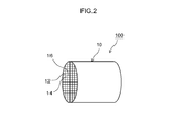
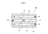
図2は、パティキュレートフィルタ100の斜視図である。図3は、パティキュレートフィルタ100を軸方向に切断した断面の一部を拡大した模式図である。図2および図3に示すように、パティキュレートフィルタ100は、ウォールフロー構造の基材10と、第1触媒部20(図4参照)と、第2触媒部30(図4参照)とを備えている。以下、基材10、第1触媒部20、第2触媒部30の順に説明する。
FIG. 2 is a perspective view of the particulate filter 100. FIG. 3 is an enlarged schematic view of a part of a cross section of the particulate filter 100 cut in the axial direction. As shown in FIGS. 2 and 3, the particulate filter 100 includes a base material 10 having a wall flow structure, a first catalyst unit 20 (see FIG. 4), and a second catalyst unit 30 (see FIG. 4). ing. Hereinafter, the base material 10, the first catalyst part 20, and the second catalyst part 30 will be described in this order.
<基材10>
基材10としては、従来のこの種の用途に用いられる種々の素材及び形態のものが使用可能である。例えば、コージェライト、炭化ケイ素(SiC)等のセラミックスまたは合金(ステンレス等)から形成された基材を好適に採用することができる。一例として外形が円筒形状(本実施形態)である基材が例示される。ただし、基材全体の外形については、円筒形に代えて、楕円筒形、多角筒形を採用してもよい。かかる基材10は、排ガス流入側の端部のみが開口した入側セル12と、該入側セル12に隣接し排ガス流出側の端部のみが開口した出側セル14と、入側セル12と出側セル14とを仕切る多孔質の隔壁16とを有している。 <Substrate 10>
As thebase material 10, various materials and forms used for this type of conventional application can be used. For example, a base material formed of a ceramic or alloy (stainless steel or the like) such as cordierite or silicon carbide (SiC) can be suitably employed. As an example, a substrate whose outer shape is a cylindrical shape (this embodiment) is illustrated. However, the outer shape of the entire substrate may be an elliptical cylinder or a polygonal cylinder instead of the cylinder. Such a base material 10 includes an inlet cell 12 that is open only at the end portion on the exhaust gas inflow side, an outlet cell 14 that is adjacent to the inlet cell 12 and is open only at the end portion on the exhaust gas outlet side, and the inlet cell 12. And a porous partition wall 16 that partitions the outlet cell 14.
基材10としては、従来のこの種の用途に用いられる種々の素材及び形態のものが使用可能である。例えば、コージェライト、炭化ケイ素(SiC)等のセラミックスまたは合金(ステンレス等)から形成された基材を好適に採用することができる。一例として外形が円筒形状(本実施形態)である基材が例示される。ただし、基材全体の外形については、円筒形に代えて、楕円筒形、多角筒形を採用してもよい。かかる基材10は、排ガス流入側の端部のみが開口した入側セル12と、該入側セル12に隣接し排ガス流出側の端部のみが開口した出側セル14と、入側セル12と出側セル14とを仕切る多孔質の隔壁16とを有している。 <
As the
<入側セル12および出側セル14>
入側セル12は、排ガス流入側の端部のみが開口しており、出側セル14は、入側セル12に隣接し排ガス流出側の端部のみが開口している。この実施形態では、入側セル12は、排ガス流出側の端部が封止部12aで目封じされており、出側セル14は、排ガス流入側の端部が封止部14aで目封じされている。入側セル12および出側セル14は、フィルタ100に供給される排ガスの流量や成分を考慮して適当な形状および大きさに設定するとよい。例えば入側セル12および出側セル14の形状は、正方形、平行四辺形、長方形、台形などの矩形、三角形、その他の多角形(例えば、六角形、八角形)、円形など種々の幾何学形状であってよい。 <Incoming cell 12 and outgoing cell 14>
Theinlet side cell 12 is open only at the end on the exhaust gas inflow side, and the outlet cell 14 is adjacent to the inlet side cell 12 and is open only at the end on the exhaust gas outflow side. In this embodiment, the inlet side cell 12 is sealed with the sealing part 12a at the end on the exhaust gas outflow side, and the outlet side cell 14 is sealed with the sealing part 14a at the end on the exhaust gas inflow side. ing. The inlet cell 12 and the outlet cell 14 may be set to appropriate shapes and sizes in consideration of the flow rate and components of the exhaust gas supplied to the filter 100. For example, the shapes of the entrance cell 12 and the exit cell 14 are various geometric shapes such as a rectangle such as a square, a parallelogram, a rectangle, and a trapezoid, a triangle, other polygons (for example, a hexagon, an octagon), and a circle. It may be.
入側セル12は、排ガス流入側の端部のみが開口しており、出側セル14は、入側セル12に隣接し排ガス流出側の端部のみが開口している。この実施形態では、入側セル12は、排ガス流出側の端部が封止部12aで目封じされており、出側セル14は、排ガス流入側の端部が封止部14aで目封じされている。入側セル12および出側セル14は、フィルタ100に供給される排ガスの流量や成分を考慮して適当な形状および大きさに設定するとよい。例えば入側セル12および出側セル14の形状は、正方形、平行四辺形、長方形、台形などの矩形、三角形、その他の多角形(例えば、六角形、八角形)、円形など種々の幾何学形状であってよい。 <
The
<隔壁16>
隣接する入側セル12と出側セル14との間には、隔壁16が形成されている。この隔壁16によって入側セル12と出側セル14とが仕切られている。隔壁16は、排ガスが通過可能な多孔質構造である。隔壁16の気孔率としては特に限定されないが、概ね50%~70%にすることが適当であり、好ましくは55%~65%である。隔壁16の気孔率が小さすぎると、圧力損失が増大してしまうことがあり、一方、隔壁16の気孔率が大きすぎると、フィルタ100の機械的強度が低下傾向になるため、好ましくない。隔壁16の厚みとしては特に限定されないが、概ね200μm~800μm程度であるとよい。このような隔壁の厚みの範囲内であると、PMの捕集効率を損なうことなく圧損の上昇を抑制する効果が得られる。 <Partition wall 16>
Apartition wall 16 is formed between the adjacent entrance cell 12 and exit cell 14. The entrance cell 12 and the exit cell 14 are partitioned by the partition wall 16. The partition wall 16 has a porous structure through which exhaust gas can pass. The porosity of the partition wall 16 is not particularly limited, but is generally 50% to 70%, preferably 55% to 65%. If the porosity of the partition wall 16 is too small, pressure loss may increase. On the other hand, if the porosity of the partition wall 16 is too large, the mechanical strength of the filter 100 tends to decrease, which is not preferable. The thickness of the partition wall 16 is not particularly limited, but is preferably about 200 μm to 800 μm. Within such a range of the partition wall thickness, an effect of suppressing an increase in pressure loss can be obtained without impairing the PM collection efficiency.
隣接する入側セル12と出側セル14との間には、隔壁16が形成されている。この隔壁16によって入側セル12と出側セル14とが仕切られている。隔壁16は、排ガスが通過可能な多孔質構造である。隔壁16の気孔率としては特に限定されないが、概ね50%~70%にすることが適当であり、好ましくは55%~65%である。隔壁16の気孔率が小さすぎると、圧力損失が増大してしまうことがあり、一方、隔壁16の気孔率が大きすぎると、フィルタ100の機械的強度が低下傾向になるため、好ましくない。隔壁16の厚みとしては特に限定されないが、概ね200μm~800μm程度であるとよい。このような隔壁の厚みの範囲内であると、PMの捕集効率を損なうことなく圧損の上昇を抑制する効果が得られる。 <
A
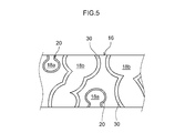
図4は、図3のIV領域を拡大した拡大模式図である。図4に示すように、隔壁16は、相対的に細孔径が小さい小細孔18aと、相対的に細孔径が大きい大細孔18bとを有している。この実施形態では、隔壁16は、その独立した大細孔18b(もしくは多数の大細孔18bの繋がり)によって隔壁16の表面と裏面とが連通し得るように構成されている。また、隔壁16は、大細孔18bよりも小さい(典型的には隔壁16を貫通していない)小細孔18aによって複雑に入り組んだ経路(貫通していない迂回した経路)が形成されている。小細孔18aの内部には、第1触媒部20が形成されている、また、大細孔18bの内部には、第2触媒部30が形成されている。
FIG. 4 is an enlarged schematic diagram in which the IV region of FIG. 3 is enlarged. As shown in FIG. 4, the partition 16 has a small pore 18a having a relatively small pore diameter and a large pore 18b having a relatively large pore diameter. In this embodiment, the partition wall 16 is configured so that the front surface and the back surface of the partition wall 16 can communicate with each other through the independent large pores 18b (or a connection of a large number of large pores 18b). In addition, the partition wall 16 is formed with a complicated path (a detour path that does not penetrate) that is smaller than the large pore 18b (typically does not penetrate the partition wall 16). . A first catalyst portion 20 is formed inside the small pore 18a, and a second catalyst portion 30 is formed inside the large pore 18b.
<第1触媒部>
第1触媒部20は、隔壁16の内部細孔18a、18bのうち小細孔18aの壁表面に形成されている。細孔径が相対的に小さい小細孔18aは、隔壁16内で複雑に入り組んだ経路を形成しているため、排ガスが長く滞留する傾向がある。そのため、小細孔18aに形成された第1触媒部20では、少量の貴金属でも排ガスが効率よく浄化される。第1触媒部20が形成された小細孔18aの細孔直径は、第2触媒部30が形成された大細孔18bの細孔直径よりも小さければよい。例えば、第1触媒部20が形成された小細孔18aのガス吸着法もしくは電子顕微鏡(Scanning Electron Microscope:SEM)での画像観察に基づく平均細孔直径は、概ね10μm以下(例えば0.1μm以上10μm以下)であることが好ましく、8μm以下であることがより好ましく、5μm以下であることが特に好ましい。このような小細孔18aの細孔直径の範囲内であると、小細孔18aに形成された第1触媒部20によって排ガスを効率よく浄化することができる。第1触媒部20によって浄化される有害成分としては特に限定されないが、例えばHC、COおよびNOxが例示される。 <First catalyst part>
Thefirst catalyst portion 20 is formed on the wall surface of the small pore 18 a among the internal pores 18 a and 18 b of the partition wall 16. Since the small pores 18a having a relatively small pore diameter form a complicated and complicated path in the partition wall 16, the exhaust gas tends to stay for a long time. Therefore, in the first catalyst part 20 formed in the small pores 18a, the exhaust gas is efficiently purified even with a small amount of noble metal. The pore diameter of the small pore 18a in which the first catalyst part 20 is formed may be smaller than the pore diameter of the large pore 18b in which the second catalyst part 30 is formed. For example, the average pore diameter based on the gas adsorption method of the small pores 18a in which the first catalyst part 20 is formed or image observation with an electron microscope (Scanning Electron Microscope: SEM) is approximately 10 μm or less (for example, 0.1 μm or more). 10 [mu] m or less), more preferably 8 [mu] m or less, and particularly preferably 5 [mu] m or less. Within the range of the pore diameter of the small pore 18a, the exhaust gas can be efficiently purified by the first catalyst portion 20 formed in the small pore 18a. Although it does not specifically limit as a harmful | toxic component refine | purified by the 1st catalyst part 20, For example, HC, CO, and NOx are illustrated.
第1触媒部20は、隔壁16の内部細孔18a、18bのうち小細孔18aの壁表面に形成されている。細孔径が相対的に小さい小細孔18aは、隔壁16内で複雑に入り組んだ経路を形成しているため、排ガスが長く滞留する傾向がある。そのため、小細孔18aに形成された第1触媒部20では、少量の貴金属でも排ガスが効率よく浄化される。第1触媒部20が形成された小細孔18aの細孔直径は、第2触媒部30が形成された大細孔18bの細孔直径よりも小さければよい。例えば、第1触媒部20が形成された小細孔18aのガス吸着法もしくは電子顕微鏡(Scanning Electron Microscope:SEM)での画像観察に基づく平均細孔直径は、概ね10μm以下(例えば0.1μm以上10μm以下)であることが好ましく、8μm以下であることがより好ましく、5μm以下であることが特に好ましい。このような小細孔18aの細孔直径の範囲内であると、小細孔18aに形成された第1触媒部20によって排ガスを効率よく浄化することができる。第1触媒部20によって浄化される有害成分としては特に限定されないが、例えばHC、COおよびNOxが例示される。 <First catalyst part>
The
<第2触媒部30>
第2触媒部30は、隔壁16の内部細孔18a、18bのうち大細孔18bの壁表面に形成されている。細孔径が相対的に大きい大細孔18bは、その独立した大細孔18bもしくは大細孔18bの繋がりによって隔壁16を厚み方向に連通しているため、排ガスが円滑に通過する傾向がある。そのため、大細孔18bに形成された第2触媒部30では、圧損を上昇させることなく排ガスが速やかに浄化される。第2触媒部30が形成された大細孔18bの細孔直径は、第1触媒部20が形成された小細孔18aの細孔直径よりも大きければよい。例えば、第2触媒部30が形成された大細孔18bのガス吸着法もしくは電子顕微鏡(SEM)での画像観察に基づく平均細孔直径は、概ね10μmを上回る(例えば10μmを超えかつ100μm以下である)ことが好ましく、15μm以上であることがより好ましく、20μm以上であることが特に好ましい。このような大細孔18bの細孔直径の範囲内であると、大細孔18bに形成された第2触媒部30によって排ガスを速やかに浄化することができる。第2触媒部30によって浄化される有害成分としては特に限定されないが、例えばHC、COおよびNOxが例示される。 <Second catalyst unit 30>
Thesecond catalyst portion 30 is formed on the wall surface of the large pore 18b among the internal pores 18a and 18b of the partition wall 16. Since the large pore 18b having a relatively large pore diameter communicates the partition wall 16 in the thickness direction by the connection of the independent large pore 18b or the large pore 18b, the exhaust gas tends to pass smoothly. Therefore, in the second catalyst part 30 formed in the large pores 18b, the exhaust gas is quickly purified without increasing the pressure loss. The pore diameter of the large pore 18b in which the second catalyst portion 30 is formed may be larger than the pore diameter of the small pore 18a in which the first catalyst portion 20 is formed. For example, the average pore diameter of the large pores 18b formed with the second catalyst portion 30 based on the gas adsorption method or image observation with an electron microscope (SEM) is generally greater than 10 μm (for example, greater than 10 μm and less than 100 μm). It is preferably 15 μm or more, more preferably 20 μm or more. Within the range of the pore diameter of the large pore 18b, the exhaust gas can be quickly purified by the second catalyst portion 30 formed in the large pore 18b. Although it does not specifically limit as a harmful | toxic component refine | purified by the 2nd catalyst part 30, For example, HC, CO, and NOx are illustrated.
第2触媒部30は、隔壁16の内部細孔18a、18bのうち大細孔18bの壁表面に形成されている。細孔径が相対的に大きい大細孔18bは、その独立した大細孔18bもしくは大細孔18bの繋がりによって隔壁16を厚み方向に連通しているため、排ガスが円滑に通過する傾向がある。そのため、大細孔18bに形成された第2触媒部30では、圧損を上昇させることなく排ガスが速やかに浄化される。第2触媒部30が形成された大細孔18bの細孔直径は、第1触媒部20が形成された小細孔18aの細孔直径よりも大きければよい。例えば、第2触媒部30が形成された大細孔18bのガス吸着法もしくは電子顕微鏡(SEM)での画像観察に基づく平均細孔直径は、概ね10μmを上回る(例えば10μmを超えかつ100μm以下である)ことが好ましく、15μm以上であることがより好ましく、20μm以上であることが特に好ましい。このような大細孔18bの細孔直径の範囲内であると、大細孔18bに形成された第2触媒部30によって排ガスを速やかに浄化することができる。第2触媒部30によって浄化される有害成分としては特に限定されないが、例えばHC、COおよびNOxが例示される。 <
The
<貴金属>
第1触媒部20および第2触媒部30は、それぞれ担体(図示省略)と、該担体に担持された貴金属(図示省略)とを備えている。第1触媒部20および第2触媒部30は、白金(Pt)、パラジウム(Pd)およびロジウム(Rh)のうちの少なくとも1種の貴金属が含まれているとよい。 <Precious metal>
Each of thefirst catalyst unit 20 and the second catalyst unit 30 includes a carrier (not shown) and a noble metal (not shown) supported on the carrier. The first catalyst unit 20 and the second catalyst unit 30 may include at least one precious metal of platinum (Pt), palladium (Pd), and rhodium (Rh).
第1触媒部20および第2触媒部30は、それぞれ担体(図示省略)と、該担体に担持された貴金属(図示省略)とを備えている。第1触媒部20および第2触媒部30は、白金(Pt)、パラジウム(Pd)およびロジウム(Rh)のうちの少なくとも1種の貴金属が含まれているとよい。 <Precious metal>
Each of the
ここで、基材の体積1L当たりについて、第1触媒部20における貴金属の含有量は、第2触媒部30における貴金属の含有量よりも少ない。この実施形態では、基材の体積1L当たりについて、第1触媒部20の成形量(コート量)と、第2触媒部30の成形量(コート量)とが等しく、かつ、第1触媒部20における担体1g当たりの貴金属の担持量が、第2触媒部30における担体1g当たりの貴金属の担持量よりも少ない。つまり、基材の体積1L当たりについて、第1触媒部20の成形量と第2触媒部30の成形量とを同程度に揃えつつ、第1触媒部20における担体1g当たりの貴金属の担持量を、第2触媒部30における担体1g当たりの貴金属の担持量よりも少なくする。
Here, the content of the noble metal in the first catalyst part 20 is less than the content of the noble metal in the second catalyst part 30 per 1 L of the volume of the base material. In this embodiment, the molding amount (coat amount) of the first catalyst unit 20 and the molding amount (coat amount) of the second catalyst unit 30 are equal to each other and the first catalyst unit 20 per 1 L of the base material volume. The amount of noble metal supported per gram of support in the catalyst is smaller than the amount of noble metal supported per gram of support in the second catalyst portion 30. That is, the amount of the precious metal supported per 1 g of the carrier in the first catalyst unit 20 is set so that the molding amount of the first catalyst unit 20 is equal to the molding amount of the second catalyst unit 30 per 1 L of the base material volume. The amount of noble metal supported per gram of support in the second catalyst unit 30 is set to be smaller.
第1触媒部20における担体1g当たりの貴金属の担持量としては、第2触媒部30における担体1g当たりの貴金属の担持量よりも小さければよい。例えば、第1触媒部20における担体1g当たりの貴金属の担持量W1と、第2触媒部30における担体1g当たりの貴金属の担持量W2との比(W1/W2)が、概ね0.6以下であることが適当であるが、0.5以下が好ましく、0.3以下が特に好ましい。
The amount of noble metal supported per gram of support in the first catalyst unit 20 may be smaller than the amount of precious metal supported per gram of carrier in the second catalyst unit 30. For example, the ratio (W1 / W2) of the precious metal loading amount W1 per gram of carrier in the first catalyst portion 20 to the precious metal loading amount W2 per gram of carrier in the second catalyst portion 30 is approximately 0.6 or less. Appropriately, it is preferably 0.5 or less, particularly preferably 0.3 or less.
ここで開示される排ガス浄化装置では、少量でも触媒活性が高い小細孔18a(第1触媒部20)における貴金属の担持量を、大細孔18b(第2触媒部30)における貴金属の担持量に比べて少なくする。このように、小細孔18aと大細孔18bとで貴金属の含有量に適度な差を設け、両者の触媒活性を適切に調整することにより、フィルタ全体での貴金属の使用量を減らしつつ、排ガスの浄化性能を効果的に向上させることができる。したがって、本構成によれば、低コストで、なおかつ浄化性能に優れた、高性能な排ガス浄化装置を提供することができる。
In the exhaust gas purification apparatus disclosed herein, the amount of noble metal supported in the small pore 18a (first catalyst portion 20) having a high catalytic activity even when the amount is small, and the amount of noble metal supported in the large pore 18b (second catalyst portion 30). Less than In this way, by providing an appropriate difference in the content of the noble metal between the small pore 18a and the large pore 18b and appropriately adjusting the catalytic activity of both, while reducing the amount of noble metal used in the entire filter, The purification performance of exhaust gas can be improved effectively. Therefore, according to this configuration, it is possible to provide a high-performance exhaust gas purification device that is low in cost and excellent in purification performance.
ここで開示される排ガス浄化装置としては、上記担持量比(W1/W2)が、(W1/W2)≦0.6を満足するものが好ましく、(W1/W2)≦0.4を満足するものがさらに好ましく、(W1/W2)≦0.3を満足するものが特に好ましい。その一方、上記担持量比(W1/W2)が0.1を下回ると、第1触媒部20の触媒活性が低下しすぎるため、所望の浄化性能が得られない場合がある。浄化性能向上の観点からは、0.1≦(W1/W2)(特には0.15≦(W1/W2))を満足するものが好ましい。例えば、上記担持量比(W1/W2)が0.1以上0.5以下(特に0.15以上0.25以下)の第1触媒部20および第2触媒部30が、浄化性能の向上と低コスト化とを両立するという観点から適当である。
As the exhaust gas purifying apparatus disclosed herein, it is preferable that the carrying amount ratio (W1 / W2) satisfies (W1 / W2) ≦ 0.6, and satisfies (W1 / W2) ≦ 0.4. More preferred are those satisfying (W1 / W2) ≦ 0.3. On the other hand, if the supported amount ratio (W1 / W2) is less than 0.1, the catalytic activity of the first catalyst unit 20 is excessively lowered, and the desired purification performance may not be obtained. From the viewpoint of improving the purification performance, those satisfying 0.1 ≦ (W1 / W2) (particularly 0.15 ≦ (W1 / W2)) are preferable. For example, the first catalyst part 20 and the second catalyst part 30 having the loading ratio (W1 / W2) of 0.1 to 0.5 (especially 0.15 to 0.25) can improve the purification performance. It is appropriate from the viewpoint of achieving both cost reduction.
この実施形態では、第1触媒部20および第2触媒部30は、貴金属としてPtおよびRhを含んでいる。第1触媒部20における担体1g当たりのPtの担持量は、概ね0.001g~0.01gであることが適当であり、好ましくは0.002g~0.008gであり、特に好ましくは0.003g~0.005gである。第2触媒部30における担体1g当たりのPtの担持量は、概ね0.005g~0.05gであることが適当であり、好ましくは0.010g~0.04gであり、特に好ましくは0.015g~0.025gである。また、第1触媒部20における担体1g当たりのRhの担持量は、概ね0.0005g~0.005gであることが適当であり、好ましくは0.0008g~0.004gであり、特に好ましくは0.001g~0.003gである。第2触媒部30における担体1g当たりのRhの担持量は、概ね0.0025g~0.025gであることが適当であり、好ましくは0.004g~0.02gであり、特に好ましくは0.005g~0.015gである。なお、第1触媒部20および第2触媒部30は、Rh、PtおよびPd以外の貴金属を含んでいてもよい。Rh、PtおよびPd以外の貴金属として、例えば、ルテニウム(Ru)、イリジウム(Ir)、オスミウム(Os)等を用いることができる。
In this embodiment, the first catalyst part 20 and the second catalyst part 30 contain Pt and Rh as noble metals. The amount of Pt supported per gram of carrier in the first catalyst portion 20 is suitably about 0.001 g to 0.01 g, preferably 0.002 g to 0.008 g, and particularly preferably 0.003 g. Is 0.005 g. The amount of Pt supported per gram of carrier in the second catalyst part 30 is suitably approximately 0.005 g to 0.05 g, preferably 0.010 g to 0.04 g, and particularly preferably 0.015 g. ~ 0.025 g. In addition, the amount of Rh supported per gram of carrier in the first catalyst portion 20 is suitably about 0.0005 g to 0.005 g, preferably 0.0008 g to 0.004 g, and particularly preferably 0. 0.001 g to 0.003 g. The amount of Rh supported per gram of carrier in the second catalyst unit 30 is suitably about 0.0025 g to 0.025 g, preferably 0.004 g to 0.02 g, and particularly preferably 0.005 g. ~ 0.015 g. In addition, the 1st catalyst part 20 and the 2nd catalyst part 30 may contain noble metals other than Rh, Pt, and Pd. As noble metals other than Rh, Pt and Pd, for example, ruthenium (Ru), iridium (Ir), osmium (Os) and the like can be used.
第1触媒部20および第2触媒部30は、PtおよびRhを担体に担持させることによって形成されている。Ptを担持させるPt担体としては、アルミナ(Al2O3)、ジルコニア(ZrO2)、セリア(CeO2)、シリカ(SiO2)、マグネシア(MgO)、酸化チタン(チタニア:TiO2)等の金属酸化物、若しくはこれらの固溶体(例えばセリア-ジルコニア(CeO2-ZrO2)複合酸化物)が挙げられる。中でもセリア-ジルコニア複合酸化物の使用が好ましい。これらの二種以上を併用してもよい。なお、上記Pt担体には、副成分として他の材料(典型的には無機酸化物)が添加されていてもよい。Pt担体に添加し得る物質としては、ランタン(La)、イットリウム(Y)等の希土類元素、カルシウムなどのアルカリ土類元素、その他遷移金属元素などが用いられ得る。上記の中でも、ランタン、イットリウム等の希土類元素は、触媒機能を阻害せずに高温における比表面積を向上できるため、安定化剤として好適に用いられる
The first catalyst part 20 and the second catalyst part 30 are formed by supporting Pt and Rh on a carrier. Examples of the Pt carrier for supporting Pt include alumina (Al 2 O 3 ), zirconia (ZrO 2 ), ceria (CeO 2 ), silica (SiO 2 ), magnesia (MgO), titanium oxide (titania: TiO 2 ), and the like. Examples thereof include metal oxides or solid solutions thereof (for example, ceria-zirconia (CeO 2 —ZrO 2 ) composite oxide). Of these, the use of ceria-zirconia composite oxide is preferred. Two or more of these may be used in combination. It should be noted that other materials (typically inorganic oxides) may be added to the Pt carrier as a subcomponent. As substances that can be added to the Pt carrier, rare earth elements such as lanthanum (La) and yttrium (Y), alkaline earth elements such as calcium, and other transition metal elements can be used. Among the above, rare earth elements such as lanthanum and yttrium are preferably used as stabilizers because they can improve the specific surface area at high temperatures without impairing the catalytic function.
上記Pt担体にPtを担持させる方法としては特に制限されない。例えばPt塩(例えば硝酸塩)やPt錯体(例えば、ジニトロジアミン錯体)を含有する水溶液に上記Pt担体を含浸させた後、乾燥させ、焼成することにより調製することができる。
The method for supporting Pt on the Pt carrier is not particularly limited. For example, it can be prepared by impregnating the Pt carrier with an aqueous solution containing a Pt salt (for example, nitrate) or a Pt complex (for example, a dinitrodiamine complex), then drying and baking.
Rhを担持させるRh担体としては、アルミナ(Al2O3)、ジルコニア(ZrO2)、セリア(CeO2)、シリカ(SiO2)、マグネシア(MgO)、酸化チタン(チタニア:TiO2)等の金属酸化物、若しくはこれらの固溶体(例えばセリア-ジルコニア(CeO2-ZrO2)複合酸化物)が挙げられる。中でもアルミナの使用が好ましい。これらの二種以上を併用してもよい。なお、上記Rh担体には、副成分として他の材料(典型的には無機酸化物)が添加されていてもよい。Rh担体に添加し得る物質としては、ランタン(La)、イットリウム(Y)等の希土類元素、カルシウムなどのアルカリ土類元素、その他遷移金属元素などが用いられ得る。上記の中でも、ランタン、イットリウム等の希土類元素は、触媒機能を阻害せずに高温における比表面積を向上できるため、安定化剤として好適に用いられる
Examples of the Rh carrier for supporting Rh include alumina (Al 2 O 3 ), zirconia (ZrO 2 ), ceria (CeO 2 ), silica (SiO 2 ), magnesia (MgO), and titanium oxide (titania: TiO 2 ). Examples thereof include metal oxides or solid solutions thereof (for example, ceria-zirconia (CeO 2 —ZrO 2 ) composite oxide). Of these, use of alumina is preferable. Two or more of these may be used in combination. Note that other materials (typically inorganic oxides) may be added to the Rh carrier as a subcomponent. As materials that can be added to the Rh carrier, rare earth elements such as lanthanum (La) and yttrium (Y), alkaline earth elements such as calcium, and other transition metal elements can be used. Among the above, rare earth elements such as lanthanum and yttrium are preferably used as stabilizers because they can improve the specific surface area at high temperatures without impairing the catalytic function.
上記Rh担体にRhを担持させる方法としては特に制限されない。例えばRh塩(例えば硝酸塩)やRh錯体(例えば、テトラアンミン錯体)を含有する水溶液に上記Rh担体を含浸させた後、乾燥させ、焼成することにより調製することができる。
The method for supporting Rh on the Rh carrier is not particularly limited. For example, it can be prepared by impregnating the Rh carrier with an aqueous solution containing an Rh salt (for example, nitrate) or an Rh complex (for example, a tetraammine complex), followed by drying and baking.
第1触媒部20および第2触媒部30は、上述した貴金属(ここではPt、Rh)および担体(ここではPt担体、Rh担体)のほか、NOx吸蔵能を有するNOx吸収材を含んでいてもよい。NOx吸収材は、排ガスの空燃比が酸素過剰のリーン状態にある状態では排ガス中のNOxを吸収し、空燃比がリッチ側に切り替えられると、吸収されていたNOxを放出するNOx吸蔵能を有するものであればよい。かかるNOx吸収材としては、NOxに電子を供与し得る金属の一種または二種以上を含む塩基性材料を好ましく用いることができる。例えば、カリウム(K)、ナトリウム(Na)、セシウム(Cs)のようなアルカリ金属、バリウム(Ba)、カルシウム(Ca)のようなアルカリ土類金属、ランタノイドのような希土類および銀(Ag)、銅(Cu)、鉄(Fe)、イリジウム(Ir)等の金属が挙げられる。中でもバリウム化合物(例えば硫酸バリウム)は高いNOx吸蔵能を有しており、ここで開示される排ガス浄化装置に用いられるNOx吸収材として好適である。
The first catalyst unit 20 and the second catalyst unit 30 may include a NOx absorbent having NOx occlusion ability in addition to the above-described noble metals (here, Pt, Rh) and carriers (here, Pt carriers, Rh carriers). Good. The NOx absorbent absorbs NOx in the exhaust gas when the air-fuel ratio of the exhaust gas is in a lean state with excess oxygen, and has a NOx occlusion ability that releases the absorbed NOx when the air-fuel ratio is switched to the rich side. Anything is acceptable. As such a NOx absorbent, a basic material containing one or more metals that can donate electrons to NOx can be preferably used. For example, alkali metals such as potassium (K), sodium (Na), cesium (Cs), alkaline earth metals such as barium (Ba), calcium (Ca), rare earths such as lanthanides and silver (Ag), Examples include metals such as copper (Cu), iron (Fe), and iridium (Ir). Among these, a barium compound (for example, barium sulfate) has a high NOx occlusion ability and is suitable as a NOx absorbent used in the exhaust gas purification apparatus disclosed herein.
また、第1触媒部20および第2触媒部30は、酸素吸蔵能を有するOSC(Oxygen Storage Capacity)材を含んでいてもよい。OSC材は、排ガスの空燃比がリーンであるとき(即ち酸素過剰側の雰囲気)には排ガス中の酸素を吸蔵し、排ガスの空燃比がリッチであるとき(即ち燃料過剰側の雰囲気)には吸蔵されている酸素を放出するものであればよい。かかるOSC材としては、例えば、酸化セリウム(セリア:CeO2)や該セリアを含む複合酸化物(例えば、セリア-ジルコニア複合酸化物(CeO2-ZrO2複合酸化物)などが挙げられる。中でもCeO2-ZrO2複合酸化物は高い酸素吸蔵能を有しており、ここで開示される排ガス浄化装置に用いられるOSC材として好適である。
The first catalyst unit 20 and the second catalyst unit 30 may include an OSC (Oxygen Storage Capacity) material having an oxygen storage capacity. The OSC material occludes oxygen in the exhaust gas when the air-fuel ratio of the exhaust gas is lean (ie, the atmosphere on the oxygen excess side), and when the air-fuel ratio of the exhaust gas is rich (ie, the atmosphere on the fuel excess side). Any device that releases the stored oxygen may be used. Examples of such OSC materials include cerium oxide (ceria: CeO 2 ) and composite oxides containing the ceria (for example, ceria-zirconia composite oxide (CeO 2 —ZrO 2 composite oxide). The 2- ZrO 2 composite oxide has a high oxygen storage capacity and is suitable as an OSC material used in the exhaust gas purification apparatus disclosed herein.
特に限定されるものではないが、第1触媒部20および第2触媒部30が貴金属および担体以外の触媒部形成成分(例えばNOx吸収材やOSC材や後述するバインダ)を含有する場合は、それら任意成分の合計含有割合を凡そ10質量%以下とすることが好ましく、凡そ8質量%以下(例えば凡そ1~5質量%)とすることが好ましい。
Although not particularly limited, when the first catalyst part 20 and the second catalyst part 30 contain a catalyst part forming component other than the noble metal and the carrier (for example, a NOx absorbent, an OSC material, or a binder described later), The total content of the optional components is preferably about 10% by mass or less, more preferably about 8% by mass or less (eg, about 1 to 5% by mass).
<第1触媒部20および第2触媒部30の形成方法>
第1触媒部20および第2触媒部30を形成するに際しては、第1触媒部20と、第2触媒部30とで異なるスラリーを基に形成するとよい。例えば、第1触媒部20を形成するための第1スラリーと、第2触媒部30を形成するための第2スラリーとを用意するとよい。 <Method for FormingFirst Catalyst Part 20 and Second Catalyst Part 30>
When thefirst catalyst unit 20 and the second catalyst unit 30 are formed, the first catalyst unit 20 and the second catalyst unit 30 may be formed based on different slurries. For example, a first slurry for forming the first catalyst part 20 and a second slurry for forming the second catalyst part 30 may be prepared.
第1触媒部20および第2触媒部30を形成するに際しては、第1触媒部20と、第2触媒部30とで異なるスラリーを基に形成するとよい。例えば、第1触媒部20を形成するための第1スラリーと、第2触媒部30を形成するための第2スラリーとを用意するとよい。 <Method for Forming
When the
第1スラリーは、前記Pt担体にPtを担持してなる粉末と、前記Rh担体にRhを担持してなる粉末と、適当な溶媒(例えばイオン交換水)とを含んでいる。第1スラリーは、隔壁16の小細孔18aに流入しやすいように、粘度および固形分率が適宜調整されているとよい。一方、第2スラリーは、前記Pt担体にPtを担持してなる粉末と、前記Rh担体にRhを担持してなる粉末と、適当な溶媒(例えばイオン交換水)とを含んでいる。第2スラリーは、隔壁16の大細孔18bに流入しやすいように、粘度および固形分率が適宜調整されているとよい。隔壁16の内部に第1スラリーおよび第2スラリーを適当に密着させるため、第1スラリーおよび第2スラリーにはバインダを含有させてもよい。バインダとしては、例えばアルミナゾル、シリカゾル等の使用が好ましい。ここで、第1スラリーにおけるPt担体1g当たりのPtの担持量は、第2スラリーにおけるPt担体1g当たりのPtの担持量よりも少ない。また、第1スラリーにおけるRh担体1g当たりのRhの担持量は、第2スラリーにおけるRh担体1g当たりのRhの担持量よりも少ない。
The first slurry contains a powder in which Pt is supported on the Pt carrier, a powder in which Rh is supported on the Rh carrier, and an appropriate solvent (for example, ion-exchanged water). It is preferable that the viscosity and the solid content of the first slurry are appropriately adjusted so that the first slurry easily flows into the small pores 18a of the partition wall 16. On the other hand, the second slurry contains a powder obtained by carrying Pt on the Pt carrier, a powder obtained by carrying Rh on the Rh carrier, and an appropriate solvent (for example, ion-exchanged water). The viscosity and solid content of the second slurry may be adjusted as appropriate so that the second slurry can easily flow into the large pores 18b of the partition wall 16. In order to properly adhere the first slurry and the second slurry to the inside of the partition wall 16, the first slurry and the second slurry may contain a binder. As the binder, for example, use of alumina sol, silica sol or the like is preferable. Here, the supported amount of Pt per 1 g of Pt carrier in the first slurry is smaller than the supported amount of Pt per 1 g of Pt carrier in the second slurry. Further, the amount of Rh supported per gram of Rh carrier in the first slurry is smaller than the amount of Rh supported per gram of Rh carrier in the second slurry.
第1触媒部20および第2触媒部30を形成するに際しては、まず、第1スラリーを隔壁16の内部にコートする。第1スラリーを隔壁16の内部にコートする方法は特に限定されない。例えば、隔壁16を第1スラリーに所定時間浸漬した後、取り出すとよい。また、隔壁16を第1スラリーから取り出した後、吸引して(あるいはガスを吹き付けて)余分な第1スラリーを取り除くとよい。ここで細孔径が相対的に小さい小細孔18aは、毛管現象の吸い込みによって第1スラリーが流入しやすい。そのため、隔壁16を第1スラリーに浸漬すると、隔壁16の小細孔18aに第1スラリーが優先的に流入する。また、細孔径が相対的に小さい小細孔18aは、毛管現象によって第1スラリーが流出しにくい。そのため、隔壁16を第1スラリーから取り出した後、吸引する(あるいはガスを吹き付ける)と、大細孔18bに充填された第1スラリーが優先的に取り除かれる。つまり、上記方法によると、小細孔18aは第1スラリーで満たされやすく、大細孔18bは第1スラリーで満たされにくい。そのため、第1スラリーを小細孔18aに優先的に充填することができる。第1スラリーを小細孔18aに充填したら、次いで乾燥・焼成するとよい。これにより、小細孔18aの壁表面に第1触媒部20が形成される。
In forming the first catalyst unit 20 and the second catalyst unit 30, first, the first slurry is coated inside the partition wall 16. The method for coating the first slurry inside the partition wall 16 is not particularly limited. For example, the partition wall 16 may be taken out after being immersed in the first slurry for a predetermined time. Further, after the partition wall 16 is taken out from the first slurry, it is preferable to remove excess first slurry by suction (or by blowing gas). Here, the first slurry is likely to flow into the small pores 18a having a relatively small pore diameter by suction of capillary action. Therefore, when the partition wall 16 is immersed in the first slurry, the first slurry preferentially flows into the small pores 18 a of the partition wall 16. In addition, the small slurry 18a having a relatively small pore diameter hardly causes the first slurry to flow out due to capillary action. Therefore, when the partition 16 is taken out from the first slurry and then sucked (or gas is blown), the first slurry filled in the large pores 18b is preferentially removed. That is, according to the above method, the small pores 18a are easily filled with the first slurry, and the large pores 18b are not easily filled with the first slurry. Therefore, the first slurry can be preferentially filled into the small pores 18a. Once the first slurry is filled into the small pores 18a, it may be dried and fired. Thereby, the 1st catalyst part 20 is formed in the wall surface of the small pore 18a.
次いで、第2スラリーを隔壁16の内部に吸引コートする。第2スラリーを隔壁16の内部にコートする方法は特に限定されない。例えば、隔壁16を第2スラリーに所定時間浸漬した後、取り出すとよい。ここで、第2スラリーは、隔壁16の大細孔18bに流入しやすいように、粘度および固形分率が適宜調整されている。また、隔壁16の小細孔18aは、第1触媒部20により既にコートされている。そのため、隔壁16を第2スラリーに浸漬すると、隔壁16の大細孔18bに第2スラリーが優先的に流入する。このようにして第2スラリーを大細孔18bに充填したら、次いで乾燥・焼成するとよい。これにより、大細孔18bの壁表面に第2触媒部30が形成される。このようにして、小細孔18aと大細孔18bとに、異なる触媒部20、30を形成することができる。
Next, the second slurry is suction-coated inside the partition wall 16. The method for coating the second slurry inside the partition wall 16 is not particularly limited. For example, the partition 16 may be taken out after being immersed in the second slurry for a predetermined time. Here, the viscosity and the solid content of the second slurry are appropriately adjusted so that the second slurry easily flows into the large pores 18b of the partition wall 16. The small pores 18 a of the partition wall 16 are already coated with the first catalyst portion 20. Therefore, when the partition wall 16 is immersed in the second slurry, the second slurry preferentially flows into the large pores 18 b of the partition wall 16. After the second slurry is filled in the large pores 18b in this way, it is then preferable to dry and fire. Thereby, the 2nd catalyst part 30 is formed in the wall surface of the large pore 18b. In this way, different catalyst portions 20 and 30 can be formed in the small pore 18a and the large pore 18b.
このパティキュレートフィルタ100は、図3に示すように、基材10の入側セル12から排ガスが流入する。入側セル12から流入した排ガスは、多孔質の隔壁16を通過して出側セル14に到達する。図3においては、入側セル12から流入した排ガスが隔壁16を通過して出側セル14に到達するルートを矢印で示している。このとき、隔壁16は多孔質構造を有しているので、排ガスがこの隔壁16を通過する間に、粒子状物質(PM)が隔壁16の表面や隔壁16の内部の細孔内に捕集される。また、図4に示すように、隔壁16の内部には、第1触媒部20および第2触媒部30が設けられているので、排ガスが隔壁16の内部を通過する間に、排ガス中の有害成分が浄化される。その際、小細孔18aに形成された第1触媒部20では、排ガスが長く滞留するため、少量の貴金属でも排ガスが効率よく浄化される。また、大細孔18bに形成された第2触媒部30では、排ガスが円滑に通過するため、圧損を上昇させることなく排ガスが速やかに浄化される。隔壁16を通過して出側セル14に到達した排ガスは、排ガス流出側の開口からフィルタ100の外部へと排出される。
In this particulate filter 100, as shown in FIG. 3, exhaust gas flows from the inlet side cell 12 of the base material 10. The exhaust gas flowing in from the inlet cell 12 passes through the porous partition wall 16 and reaches the outlet cell 14. In FIG. 3, an arrow indicates a route through which the exhaust gas flowing from the entry side cell 12 passes through the partition wall 16 and reaches the exit side cell 14. At this time, since the partition wall 16 has a porous structure, particulate matter (PM) is collected on the surface of the partition wall 16 or in the pores inside the partition wall 16 while the exhaust gas passes through the partition wall 16. Is done. Further, as shown in FIG. 4, the first catalyst portion 20 and the second catalyst portion 30 are provided inside the partition wall 16, so that the exhaust gas is harmful in the exhaust gas while passing through the partition wall 16. Ingredients are purified. At that time, in the first catalyst part 20 formed in the small pores 18a, the exhaust gas stays long, so that the exhaust gas is efficiently purified even with a small amount of noble metal. Moreover, in the 2nd catalyst part 30 formed in the large pore 18b, since exhaust gas passes smoothly, exhaust gas is purified rapidly, without raising a pressure loss. The exhaust gas that has passed through the partition wall 16 and has reached the exit side cell 14 is discharged from the opening on the exhaust gas outflow side to the outside of the filter 100.
<第2実施形態>
図5は、第2実施形態に係る隔壁16の断面を示す模式図である。この実施形態では、第1触媒部20における担体1g当たりの貴金属の担持量と、第2触媒部30における担体1g当たりの貴金属の担持量とが等しく、かつ、基材の体積1L当たりについて、第1触媒部20の成形量(コート量)が、第2触媒部30の成形量(コート量)よりも小さい。つまり、第1触媒部20における担体1g当たりの貴金属の担持量と、第2触媒部30における担体1g当たりの貴金属の担持量とを同程度に揃えつつ、基材の体積1L当たりについて、第1触媒部20の成形量を、第2触媒部30の成形量よりも小さくする。 Second Embodiment
FIG. 5 is a schematic view showing a cross section of thepartition wall 16 according to the second embodiment. In this embodiment, the amount of noble metal supported per gram of support in the first catalyst unit 20 is equal to the amount of noble metal supported per gram of support in the second catalyst unit 30 and the volume per liter of the substrate is the first. The molding amount (coat amount) of the first catalyst unit 20 is smaller than the molding amount (coat amount) of the second catalyst unit 30. That is, the first catalyst part 20 has a precious metal loading amount per 1 g of carrier and the second catalyst part 30 has a same amount of precious metal loading per 1 g of carrier, and the first catalyst portion 20 has the same amount of noble metal loading per liter of the substrate. The molding amount of the catalyst part 20 is made smaller than the molding amount of the second catalyst part 30.
図5は、第2実施形態に係る隔壁16の断面を示す模式図である。この実施形態では、第1触媒部20における担体1g当たりの貴金属の担持量と、第2触媒部30における担体1g当たりの貴金属の担持量とが等しく、かつ、基材の体積1L当たりについて、第1触媒部20の成形量(コート量)が、第2触媒部30の成形量(コート量)よりも小さい。つまり、第1触媒部20における担体1g当たりの貴金属の担持量と、第2触媒部30における担体1g当たりの貴金属の担持量とを同程度に揃えつつ、基材の体積1L当たりについて、第1触媒部20の成形量を、第2触媒部30の成形量よりも小さくする。 Second Embodiment
FIG. 5 is a schematic view showing a cross section of the
基材の体積1L当たりについて、第1触媒部20の成形量は、第2触媒部30の成形量よりも小さければよい。例えば、基材の体積1L当たりについて、第1触媒部20の成形量C1と、第2触媒部30の成形量C2の比(C1/C2)が、概ね0.7以下であることが適当であるが、0.6以下が好ましく、0.5以下(例えば0.45以下)が特に好ましい。
The molding amount of the first catalyst part 20 only needs to be smaller than the molding amount of the second catalyst part 30 per 1 L of the volume of the base material. For example, it is appropriate that the ratio (C1 / C2) of the molding amount C1 of the first catalyst unit 20 and the molding amount C2 of the second catalyst unit 30 is approximately 0.7 or less per 1 L of the base material volume. However, 0.6 or less is preferable, and 0.5 or less (for example, 0.45 or less) is particularly preferable.
ここで開示される排ガス浄化装置では、少量でも触媒活性が高い小細孔18aに形成された第1触媒部20の成形量(ひいては貴金属の含有量)を、大細孔18bに形成された第2触媒部30の成形量(ひいては貴金属の含有量)に比べて少なくする。このように、小細孔18a(第1触媒部20)と大細孔18b(第2触媒部30)とで貴金属の含有量に適度な差を設け、両者の触媒活性を適切に調整することにより、フィルタ全体での貴金属の使用量を減らしつつ、排ガスの浄化性能を効果的に向上させることができる。したがって、本構成によれば、低コストで、なおかつ浄化性能に優れた、高性能な排ガス浄化装置を提供することができる。
In the exhaust gas purifying apparatus disclosed herein, the molding amount of the first catalyst portion 20 formed in the small pores 18a having high catalytic activity even in a small amount (and hence the content of the noble metal) is changed to the first amount formed in the large pores 18b. 2 Reduced compared to the molding amount of the catalyst portion 30 (and consequently the content of the noble metal). As described above, an appropriate difference is provided in the noble metal content between the small pore 18a (first catalyst portion 20) and the large pore 18b (second catalyst portion 30), and the catalytic activity of the two is appropriately adjusted. Thus, the exhaust gas purification performance can be effectively improved while reducing the amount of precious metal used in the entire filter. Therefore, according to this configuration, it is possible to provide a high-performance exhaust gas purification device that is low in cost and excellent in purification performance.
ここで開示される排ガス浄化装置としては、上記成形量(コート量)比(C1/C2)が、(C1/C2)≦0.7を満足するものが好ましく、(C1/C2)≦0.6を満足するものがさらに好ましく、(C1/C2)≦0.5を満足するものが特に好ましい。その一方、上記成形量比(C1/C2)が0.2を下回ると、第1触媒部20の触媒活性が低下しすぎるため、所望の浄化性能が得られない場合がある。浄化性能向上の観点からは、0.2≦(C1/C2)(特には0.3≦(C1/C2))を満足するものが好ましい。例えば、上記成形量比(C1/C2)が0.2以上0.5以下(特に0.3以上0.45以下)の第1触媒部20および第2触媒部30が、浄化性能の向上と低コスト化とを両立するという観点から適当である。
As the exhaust gas purification device disclosed herein, it is preferable that the molding amount (coating amount) ratio (C1 / C2) satisfies (C1 / C2) ≦ 0.7, and (C1 / C2) ≦ 0. Those satisfying 6 are more preferable, and those satisfying (C1 / C2) ≦ 0.5 are particularly preferable. On the other hand, if the molding amount ratio (C1 / C2) is less than 0.2, the catalytic activity of the first catalyst unit 20 is excessively lowered, and the desired purification performance may not be obtained. From the viewpoint of improving the purification performance, those satisfying 0.2 ≦ (C1 / C2) (particularly 0.3 ≦ (C1 / C2)) are preferable. For example, the first catalyst part 20 and the second catalyst part 30 having the molding amount ratio (C1 / C2) of 0.2 or more and 0.5 or less (particularly 0.3 or more and 0.45 or less) can improve the purification performance. It is appropriate from the viewpoint of achieving both cost reduction.
具体的には、第1触媒部20の成形量は、基材の体積1L当たり、概ね10g~50gにすることが適当であり、好ましくは20g~40gである。また、第2触媒部30の成形量は、基材の体積1L当たり、概ね50g~100gにすることが適当であり、好ましくは60g~80gである。このような第1触媒部20および第2触媒部30の成形量の範囲内であると、排ガスの浄化性能をより良く向上させることができる。
Specifically, the molding amount of the first catalyst part 20 is suitably about 10 g to 50 g, preferably 20 g to 40 g, per liter of the substrate volume. The molding amount of the second catalyst part 30 is suitably about 50 g to 100 g, preferably 60 g to 80 g, per liter of the substrate volume. When the amount of the first catalyst part 20 and the second catalyst part 30 is within the range of the molding amount, the exhaust gas purification performance can be further improved.
以下、本発明に関する試験例を説明するが、本発明を以下の試験例に示すものに限定することを意図したものではない。
Hereinafter, test examples relating to the present invention will be described, but the present invention is not intended to be limited to those shown in the following test examples.
<実施例1>
実施例1では、基材の体積1L当たりについて、第1触媒部20の成形量と第2触媒部30の成形量とを同程度に揃えつつ、第1触媒部20における担体1g当たりの貴金属の担持量が、第2触媒部30における担体1g当たりの貴金属の担持量よりも小さいフィルタ触媒を作製した。ここでは貴金属として、PtおよびRhを使用した。また、Ptを担持するPt担体としてセリア-ジルコニア複合酸化物を使用し、Rhを担持するRh担体としてLa安定化アルミナを使用した。 <Example 1>
In Example 1, per 1 L of the volume of the base material, the forming amount of thefirst catalyst part 20 and the forming amount of the second catalyst part 30 are made equal, and the precious metal per 1 g of carrier in the first catalyst part 20 is equalized. A filter catalyst having a loading amount smaller than the loading amount of the noble metal per 1 g of the carrier in the second catalyst portion 30 was produced. Here, Pt and Rh were used as noble metals. In addition, ceria-zirconia composite oxide was used as a Pt carrier supporting Pt, and La stabilized alumina was used as an Rh carrier supporting Rh.
実施例1では、基材の体積1L当たりについて、第1触媒部20の成形量と第2触媒部30の成形量とを同程度に揃えつつ、第1触媒部20における担体1g当たりの貴金属の担持量が、第2触媒部30における担体1g当たりの貴金属の担持量よりも小さいフィルタ触媒を作製した。ここでは貴金属として、PtおよびRhを使用した。また、Ptを担持するPt担体としてセリア-ジルコニア複合酸化物を使用し、Rhを担持するRh担体としてLa安定化アルミナを使用した。 <Example 1>
In Example 1, per 1 L of the volume of the base material, the forming amount of the
具体的には、Pt担体としてのセリア-ジルコニア複合酸化物を用意し、貴金属触媒溶液としてジニトロジアミンPt溶液に含浸させた後、蒸発乾固してPtを担持したPt/セリア-ジルコニア複合酸化物担体粉末を調製した。上記Pt担体(セリア-ジルコニア複合酸化物)1g当たりのPtの担持量は凡そ0.004gとした。また、Rh担体としてのLa安定化アルミナを用意し、貴金属触媒溶液として硝酸Rh溶液に含浸させた後、蒸発乾固してRhを担持したRh/アルミナ担体粉末を調製した。上記Rh担体(アルミナ)1g当たりのRhの担持量は凡そ0.0011gとした。上記Pt/セリア-ジルコニア複合酸化物担体粉末と、上記Rh/アルミナ担体粉末と、アルミナバインダと、イオン交換水とを混合して第1触媒部形成用スラリーを調製した。第1触媒部形成用スラリーは、隔壁の小細孔18aに流入しやすいように、粘度および固形分率を適宜調整した。次いで、この第1触媒部形成用スラリーにコージェライト製のウォールフロー型基材(直径103mm、全長105mm)を浸漬し、余分なスラリーを吹き払った後、乾燥・焼成することにより、隔壁16の小細孔18aの内部に第1触媒部20を形成した。第1触媒部20の成形量(コート量)は、基材1L当たり50gとした。
Specifically, a Pt / ceria-zirconia composite oxide in which a ceria-zirconia composite oxide as a Pt support is prepared, impregnated in a dinitrodiamine Pt solution as a noble metal catalyst solution, and evaporated to dryness is supported. A carrier powder was prepared. The amount of Pt supported per gram of the Pt support (ceria-zirconia composite oxide) was about 0.004 g. Also, La stabilized alumina as an Rh carrier was prepared, impregnated with a Rh nitrate solution as a noble metal catalyst solution, and then evaporated to dryness to prepare an Rh / alumina carrier powder carrying Rh. The amount of Rh supported per gram of the Rh carrier (alumina) was about 0.0011 g. The Pt / ceria-zirconia composite oxide support powder, the Rh / alumina support powder, the alumina binder, and ion-exchanged water were mixed to prepare a first catalyst part forming slurry. The slurry for forming the first catalyst part was appropriately adjusted in viscosity and solid content so as to easily flow into the small pores 18a of the partition walls. Next, a wall flow type substrate (diameter: 103 mm, total length: 105 mm) made of cordierite is immersed in the slurry for forming the first catalyst part, and after the excess slurry is blown off, drying and firing are performed, so that the partition 16 The 1st catalyst part 20 was formed in the inside of the small pore 18a. The molding amount (coat amount) of the first catalyst unit 20 was 50 g per liter of the base material.
次いで、第2触媒部形成用スラリーを上述した第1触媒部形成用スラリーと同様の手順で作製した。ただし、上記Pt担体(セリア-ジルコニア複合酸化物)1g当たりのPtの担持量は凡そ0.02g(第1触媒部の5倍)とし、上記Rh担体(アルミナ)1g当たりのRhの担持量は凡そ0.0055g(第1触媒部の5倍)とした。また、第2触媒部形成用スラリーは、隔壁の大細孔18bに流入しやすいように、粘度および固形分率を適宜調整した。そして、第2触媒部形成用スラリーに上記ウォールフロー型基材を浸漬し、余分なスラリーを吹き払った後、乾燥・焼成することにより、隔壁16の大細孔18bの内部に第2触媒部30を形成した。第2触媒部30の成形量(コート量)は、基材1L当たり50gとした。このようにして、隔壁内部に第1触媒部20および第2触媒部30が形成されたフィルタ触媒を作製した。なお、基材の体積1L当たりについて、フィルタ触媒全体でのPtの含有量は0.6g/L、Rhの含有量は0.15g/L、Pt担体の含有量は50g/L、Rh担体の含有量は45g/L、バインダの含有量は5g/Lとなる。
Next, the second catalyst part forming slurry was prepared in the same procedure as the first catalyst part forming slurry described above. However, the supported amount of Pt per 1 g of the Pt support (ceria-zirconia composite oxide) is about 0.02 g (5 times the first catalyst part), and the supported amount of Rh per 1 g of the Rh support (alumina) is About 0.0055 g (5 times the first catalyst part) was used. Further, the viscosity and solid content of the second catalyst part forming slurry were adjusted as appropriate so that the slurry for forming the second catalyst part easily flows into the large pores 18b of the partition walls. Then, the wall flow type substrate is immersed in the slurry for forming the second catalyst portion, and after the excess slurry is blown off, the second catalyst portion is placed inside the large pores 18b of the partition wall 16 by drying and firing. 30 was formed. The molding amount (coat amount) of the second catalyst part 30 was 50 g per liter of the base material. In this way, a filter catalyst in which the first catalyst part 20 and the second catalyst part 30 were formed inside the partition wall was produced. In addition, per 1 L of the volume of the substrate, the Pt content in the entire filter catalyst is 0.6 g / L, the Rh content is 0.15 g / L, the Pt carrier content is 50 g / L, and the Rh carrier The content is 45 g / L, and the binder content is 5 g / L.
<比較例1>
また、比較のために、比較例1に係る触媒部形成用スラリーを上述した第1触媒部形成用スラリーと同様の手順で作製した。ただし、上記Pt担体(セリア-ジルコニア複合酸化物)1g当たりのPtの担持量は凡そ0.012gとし、上記Rh担体(アルミナ)1g当たりのRhの担持量は凡そ0.033gとした。また、このスラリーは、隔壁の小細孔18aおよび大細孔18bの双方に流入しやすいように、粘度および固形分率を適宜調整した。そして、該スラリーにウォールフロー型基材を浸漬し、余分なスラリーを吹き払った後、乾燥・焼成することにより、隔壁16の小細孔18aおよび大細孔18bの内部に触媒部を形成した。触媒部の成形量(コート量)は、基材1L当たり100gとした。なお、基材の体積1L当たりについて、フィルタ触媒全体でのPt、Rh、Pt担体、Rh担体およびバインダの含有量は実施例1と同じである。 <Comparative Example 1>
Further, for comparison, a catalyst part forming slurry according to Comparative Example 1 was prepared in the same procedure as the first catalyst part forming slurry described above. However, the amount of Pt supported per gram of the Pt carrier (ceria-zirconia composite oxide) was about 0.012 g, and the amount of Rh supported per gram of the Rh carrier (alumina) was about 0.033 g. Further, the viscosity and solid content ratio of this slurry were adjusted as appropriate so that the slurry easily flows into both thesmall pore 18a and the large pore 18b of the partition wall. Then, a wall flow type substrate was immersed in the slurry, and excess slurry was blown off, followed by drying and firing, thereby forming a catalyst portion inside the small pore 18a and the large pore 18b of the partition wall 16. . The molding amount (coat amount) of the catalyst part was 100 g per liter of the base material. The content of Pt, Rh, Pt carrier, Rh carrier, and binder in the entire filter catalyst is the same as in Example 1 per 1 L of the substrate volume.
また、比較のために、比較例1に係る触媒部形成用スラリーを上述した第1触媒部形成用スラリーと同様の手順で作製した。ただし、上記Pt担体(セリア-ジルコニア複合酸化物)1g当たりのPtの担持量は凡そ0.012gとし、上記Rh担体(アルミナ)1g当たりのRhの担持量は凡そ0.033gとした。また、このスラリーは、隔壁の小細孔18aおよび大細孔18bの双方に流入しやすいように、粘度および固形分率を適宜調整した。そして、該スラリーにウォールフロー型基材を浸漬し、余分なスラリーを吹き払った後、乾燥・焼成することにより、隔壁16の小細孔18aおよび大細孔18bの内部に触媒部を形成した。触媒部の成形量(コート量)は、基材1L当たり100gとした。なお、基材の体積1L当たりについて、フィルタ触媒全体でのPt、Rh、Pt担体、Rh担体およびバインダの含有量は実施例1と同じである。 <Comparative Example 1>
Further, for comparison, a catalyst part forming slurry according to Comparative Example 1 was prepared in the same procedure as the first catalyst part forming slurry described above. However, the amount of Pt supported per gram of the Pt carrier (ceria-zirconia composite oxide) was about 0.012 g, and the amount of Rh supported per gram of the Rh carrier (alumina) was about 0.033 g. Further, the viscosity and solid content ratio of this slurry were adjusted as appropriate so that the slurry easily flows into both the
上記得られた実施例1および比較例1に係るフィルタ触媒の断面SEM像を観察した。実施例1の結果を図6、比較例1の結果を図9に示す。また、電子線マイクロアナライザー(EPMA)を用いてCe(ひいてはPt担体)の分散状態を観察した。実施例1の結果を図7、比較例1の結果を図10に示す。さらに、EPMAを用いてPtの分散状態を観察した。実施例1の結果を図8、比較例1の結果を図11に示す。
The cross-sectional SEM images of the filter catalysts according to Example 1 and Comparative Example 1 obtained above were observed. The result of Example 1 is shown in FIG. 6, and the result of Comparative Example 1 is shown in FIG. Moreover, the dispersion state of Ce (and thus Pt carrier) was observed using an electron beam microanalyzer (EPMA). The results of Example 1 are shown in FIG. 7, and the results of Comparative Example 1 are shown in FIG. Furthermore, the dispersion state of Pt was observed using EPMA. The result of Example 1 is shown in FIG. 8, and the result of Comparative Example 1 is shown in FIG.
図6~図8に示すように、EPMAを用いたCeおよびPtのマッピングの比較から、実施例1のフィルタ触媒では、Ce濃度が高い細孔(Pt担体が多く存在している細孔)において、Pt濃度が高い部位と、Pt濃度が低い部位とが共存していることが確認された。また、Pt濃度が高い部位は隔壁の大細孔18bに主に形成され、Pt濃度が低い部位は隔壁の小細孔18aに主に形成されていることが確認された。これに対し、図9~図11に示すように、比較例1のフィルタ触媒は、Ce濃度が高い細孔(すなわちPt担体が多く存在している細孔)のすべてに同濃度のPtが一様に担持されており、小細孔18aと大細孔18bの区別なく、同濃度のPtが担持されていることが確認された。
As shown in FIGS. 6 to 8, from the comparison of Ce and Pt mapping using EPMA, in the filter catalyst of Example 1, in the pores with high Ce concentration (pores in which many Pt carriers exist) It was confirmed that the part where the Pt concentration is high and the part where the Pt concentration is low coexist. Further, it was confirmed that the portion where the Pt concentration is high is mainly formed in the large pore 18b of the partition wall, and the portion where the Pt concentration is low is mainly formed in the small pore 18a of the partition wall. On the other hand, as shown in FIGS. 9 to 11, the filter catalyst of Comparative Example 1 has the same concentration of Pt in all the pores with a high Ce concentration (that is, the pores in which many Pt carriers are present). It was confirmed that the same concentration of Pt was supported without distinction between the small pores 18a and the large pores 18b.
上記実施例1および比較例1のフィルタ触媒について、100℃~600℃(昇温速度20℃/分)の昇温時におけるHCガスの浄化率を連続的に測定し、50%浄化温度(温度特性)を測定した。ここで50%浄化温度とは、HCガスの浄化率が50%に達したときの触媒入口のガス温度である。結果を図12に示す。図12は、実施例1および比較例1の50%浄化温度(温度特性)を示すグラフである。
For the filter catalysts of Example 1 and Comparative Example 1 above, the purification rate of HC gas at a temperature increase of 100 ° C. to 600 ° C. (temperature increase rate 20 ° C./min) was continuously measured, and a 50% purification temperature (temperature Characteristic). Here, the 50% purification temperature is the gas temperature at the catalyst inlet when the HC gas purification rate reaches 50%. The results are shown in FIG. FIG. 12 is a graph showing the 50% purification temperature (temperature characteristics) of Example 1 and Comparative Example 1.
図12に示すように、比較例1のフィルタ触媒は、HCの50%浄化温度が390℃を超えていた。これに対し、実施例1のフィルタ触媒は、フィルタ全体で比較例1と同量の貴金属を用いているにも関わらず、HCの50%浄化温度がより低く、より触媒活性に優れるものとなった。実施例1では、隔壁内の小細孔(第1触媒部)と大細孔(第2触媒部)とで担体1g当たりの貴金属の担持量(ひいては貴金属の含有量)に適度な差を設け、両者の触媒活性を適切に調整することにより、排ガスの浄化性能を効果的に向上させることができたものと推測される。この結果から、隔壁内の小細孔の貴金属の含有量を大細孔の貴金属の含有量よりも小さくすることで、触媒性能が向上し得ることが確認された。
As shown in FIG. 12, the filter catalyst of Comparative Example 1 had a 50% purification temperature of HC exceeding 390 ° C. In contrast, the filter catalyst of Example 1 has a lower HC 50% purification temperature and better catalytic activity despite the use of the same amount of precious metal as Comparative Example 1 in the entire filter. It was. In Example 1, there is an appropriate difference in the amount of precious metal supported per gram of support (and hence the content of precious metal) between the small pore (first catalyst portion) and the large pore (second catalyst portion) in the partition wall. It is presumed that the exhaust gas purification performance could be effectively improved by appropriately adjusting the catalytic activity of both. From this result, it was confirmed that the catalyst performance can be improved by making the content of the noble metal with small pores in the partition walls smaller than the content of the noble metal with large pores.
<実施例2>
実施例2では、担体1g当たりについて、第1触媒部20における担体1g当たりの貴金属の担持量と、第2触媒部30における担体1g当たりの貴金属の担持量とを同程度に揃えつつ、第1触媒部20の成形量が、第2触媒部30の成形量よりも小さいフィルタ触媒を作製した。 <Example 2>
In Example 2, the amount of the precious metal supported per gram of the carrier in thefirst catalyst part 20 and the amount of the precious metal supported per gram of the second catalyst part 30 in the first catalyst unit 20 are adjusted to the same level. A filter catalyst in which the molding amount of the catalyst part 20 was smaller than the molding amount of the second catalyst part 30 was produced.
実施例2では、担体1g当たりについて、第1触媒部20における担体1g当たりの貴金属の担持量と、第2触媒部30における担体1g当たりの貴金属の担持量とを同程度に揃えつつ、第1触媒部20の成形量が、第2触媒部30の成形量よりも小さいフィルタ触媒を作製した。 <Example 2>
In Example 2, the amount of the precious metal supported per gram of the carrier in the
具体的には、Pt担体としてのセリア-ジルコニア複合酸化物を用意し、貴金属触媒溶液としてジニトロジアミンPt溶液に含浸させた後、蒸発乾固してPtを担持したPt/セリア-ジルコニア複合酸化物担体粉末を調製した。上記Pt担体(セリア-ジルコニア複合酸化物)1g当たりのPtの担持量は凡そ0.012gとした。また、Rh担体としてのLa安定化アルミナを用意し、貴金属触媒溶液として硝酸Rh溶液に含浸させた後、蒸発乾固してRhを担持したRh/アルミナ担体粉末を調製した。上記Rh担体(アルミナ)1g当たりのRhの担持量は凡そ0.033gとした。上記Pt/セリア-ジルコニア複合酸化物担体粉末と、上記Rh/アルミナ担体粉末と、アルミナバインダと、イオン交換水とを混合して第1触媒部形成用スラリーを調製した。第1触媒部形成用スラリーは、隔壁の小細孔18aに流入しやすいように、粘度および固形分率を適宜調整した。次いで、この第1触媒部形成用スラリーにコージェライト製のウォールフロー型基材(直径103mm、全長105mm)を浸漬し、余分なスラリーを吹き払った後、乾燥・焼成することにより、隔壁16の小細孔18aの内部に第1触媒部20を形成した。第1触媒部20の成形量(コート量)は、基材1L当たり30gとした。
Specifically, a Pt / ceria-zirconia composite oxide in which a ceria-zirconia composite oxide as a Pt support is prepared, impregnated in a dinitrodiamine Pt solution as a noble metal catalyst solution, and evaporated to dryness is supported. A carrier powder was prepared. The amount of Pt supported per gram of the Pt support (ceria-zirconia composite oxide) was about 0.012 g. Also, La stabilized alumina as an Rh carrier was prepared, impregnated with a Rh nitrate solution as a noble metal catalyst solution, and then evaporated to dryness to prepare an Rh / alumina carrier powder carrying Rh. The amount of Rh supported per gram of the Rh carrier (alumina) was about 0.033 g. The Pt / ceria-zirconia composite oxide support powder, the Rh / alumina support powder, the alumina binder, and ion-exchanged water were mixed to prepare a first catalyst part forming slurry. The slurry for forming the first catalyst part was appropriately adjusted in viscosity and solid content so as to easily flow into the small pores 18a of the partition walls. Next, a wall flow type substrate (diameter: 103 mm, total length: 105 mm) made of cordierite is immersed in the slurry for forming the first catalyst part, and after the excess slurry is blown off, drying and firing are performed, so that the partition 16 The 1st catalyst part 20 was formed in the inside of the small pore 18a. The molding amount (coat amount) of the first catalyst part 20 was 30 g per 1 L of the base material.
次いで、第2触媒部形成用スラリーを上述した第1触媒部形成用スラリーと同様の手順で作製した。ただし、第2触媒部形成用スラリーは、隔壁の大細孔18bに流入しやすいように、粘度および固形分率を適宜調整した。そして、第2触媒部形成用スラリーにコージェライト製のウォールフロー型基材(直径103mm、全長105mm)を再度浸漬し、余分なスラリーを吹き払った後、乾燥・焼成することにより、隔壁16の大細孔18bの内部に第2触媒部30を形成した。第2触媒部30の成形量(コート量)は、基材1L当たり70gとした。なお、基材の体積1L当たりについて、フィルタ触媒全体でのPtの含有量は0.6g/L、Rhの含有量は0.15g/L、Pt担体の含有量は50g/L、Rh担体の含有量は45g/L、バインダの含有量は5g/Lとなる。
Next, the second catalyst part forming slurry was prepared in the same procedure as the first catalyst part forming slurry described above. However, the viscosity and solid content ratio of the second catalyst portion forming slurry were adjusted as appropriate so that the slurry for forming the second catalyst portion easily flows into the large pores 18b of the partition walls. Then, a wall flow type substrate made of cordierite (diameter: 103 mm, total length: 105 mm) is again immersed in the slurry for forming the second catalyst part, and after the excess slurry is blown off, drying and baking are performed, so that the partition 16 The second catalyst part 30 was formed inside the large pore 18b. The molding amount (coat amount) of the second catalyst unit 30 was 70 g per liter of the base material. In addition, per 1 L of the volume of the substrate, the Pt content in the entire filter catalyst is 0.6 g / L, the Rh content is 0.15 g / L, the Pt carrier content is 50 g / L, and the Rh carrier The content is 45 g / L, and the binder content is 5 g / L.
<比較例2>
また、比較のために、比較例2に係る触媒部形成用スラリーを上述した第1触媒部形成用スラリーと同様の手順で作製した。ただし、このスラリーは、隔壁の小細孔18aおよび大細孔18bの双方に流入しやすいように、粘度および固形分率を適宜調整した。該スラリーにコージェライト製のウォールフロー型基材(直径103mm、全長105mm)を浸漬し、余分なスラリーを吹き払った後、乾燥・焼成することにより、隔壁16の小細孔18aおよび大細孔18bの内部に触媒部を形成した。触媒部の成形量(コート量)は、基材1L当たり100gとした。なお、基材の体積1L当たりについて、フィルタ触媒全体でのPt、Rh、Pt担体、Rh担体およびバインダの含有量は実施例2と同じである。 <Comparative example 2>
For comparison, a catalyst part forming slurry according to Comparative Example 2 was prepared in the same procedure as the first catalyst part forming slurry described above. However, the viscosity and the solid content of the slurry were adjusted as appropriate so that the slurry easily flows into both thesmall pore 18a and the large pore 18b of the partition wall. A cordierite-made wall flow base material (diameter: 103 mm, total length: 105 mm) is immersed in the slurry, and the excess slurry is blown off, followed by drying and firing. A catalyst part was formed inside 18b. The molding amount (coat amount) of the catalyst part was 100 g per liter of the base material. The content of Pt, Rh, Pt carrier, Rh carrier, and binder in the entire filter catalyst is the same as in Example 2 per 1 L of the substrate volume.
また、比較のために、比較例2に係る触媒部形成用スラリーを上述した第1触媒部形成用スラリーと同様の手順で作製した。ただし、このスラリーは、隔壁の小細孔18aおよび大細孔18bの双方に流入しやすいように、粘度および固形分率を適宜調整した。該スラリーにコージェライト製のウォールフロー型基材(直径103mm、全長105mm)を浸漬し、余分なスラリーを吹き払った後、乾燥・焼成することにより、隔壁16の小細孔18aおよび大細孔18bの内部に触媒部を形成した。触媒部の成形量(コート量)は、基材1L当たり100gとした。なお、基材の体積1L当たりについて、フィルタ触媒全体でのPt、Rh、Pt担体、Rh担体およびバインダの含有量は実施例2と同じである。 <Comparative example 2>
For comparison, a catalyst part forming slurry according to Comparative Example 2 was prepared in the same procedure as the first catalyst part forming slurry described above. However, the viscosity and the solid content of the slurry were adjusted as appropriate so that the slurry easily flows into both the
上記実施例2および比較例2のフィルタ触媒について、100℃~600℃(昇温速度20℃/分)の昇温時におけるHCガスの浄化率を連続的に測定し、50%浄化温度(温度特性)を測定した。結果を図13に示す。図13は、実施例2および比較例2の50%浄化温度(温度特性)を示すグラフである。
For the filter catalysts of Example 2 and Comparative Example 2 above, the purification rate of HC gas at a temperature rise of 100 ° C. to 600 ° C. (temperature increase rate 20 ° C./min) was continuously measured, and a 50% purification temperature (temperature Characteristic). The results are shown in FIG. FIG. 13 is a graph showing the 50% purification temperature (temperature characteristics) of Example 2 and Comparative Example 2.
図13に示すように、比較例2のフィルタ触媒は、HCの50%浄化温度が390℃を超えていた。これに対し、実施例2のフィルタ触媒は、フィルタ全体で比較例2と同量の貴金属を用いているにも関わらず、HCの50%浄化温度がより低く、より触媒活性に優れるものとなった。実施例2では、隔壁内の小細孔(第1触媒部)と大細孔(第2触媒部)とで成形量(ひいては貴金属の含有量)に適度な差を設け、両者の触媒活性を適切に調整することにより、排ガスの浄化性能を効果的に向上させることができたものと推測される。この結果から、隔壁内の小細孔の第1触媒部の成形量を大細孔の第2触媒部の成形量よりも小さくすることで、触媒性能が向上し得ることが確認された。
As shown in FIG. 13, in the filter catalyst of Comparative Example 2, the 50% purification temperature of HC exceeded 390 ° C. In contrast, the filter catalyst of Example 2 has a lower HC 50% purification temperature and better catalytic activity despite the use of the same amount of precious metal as Comparative Example 2 in the entire filter. It was. In Example 2, there is an appropriate difference in the molding amount (and hence the noble metal content) between the small pores (first catalyst portion) and the large pores (second catalyst portion) in the partition wall, and the catalytic activity of the two is increased. It is presumed that the exhaust gas purification performance could be effectively improved by adjusting appropriately. From this result, it was confirmed that the catalyst performance could be improved by making the molding amount of the first catalyst part with small pores in the partition wall smaller than the molding amount of the second catalyst part with large pores.
以上、パティキュレートフィルタ100ならびに該パティキュレートフィルタ100を備えた排ガス浄化装置1について種々の改変例を例示したが、パティキュレートフィルタ100ならびに排ガス浄化装置1の構造は、上述した何れの実施形態にも限定されない。
排ガス浄化装置1の各部材、部位の形状や構造についても変更してもよい。図1に示した例では、フィルタ部の上流側に触媒部を設けているが、触媒部は省略しても構わない。この排ガス浄化装置1は、例えば、ガソリンエンジンなど、排気温度が比較的高い排ガス中の有害成分を浄化する装置として特に好適である。ただし、本発明に係る排ガス浄化装置1は、ガソリンエンジンの排ガス中の有害成分を浄化する用途に限らず、他のエンジン(例えばディーゼルエンジン)から排出された排ガス中の有害成分を浄化する種々の用途にて用いることができる。 As described above, various modifications of theparticulate filter 100 and the exhaust gas purification device 1 including the particulate filter 100 have been illustrated. However, the structure of the particulate filter 100 and the exhaust gas purification device 1 is the same in any of the above-described embodiments. It is not limited.
You may change also about the shape and structure of each member of the exhaustgas purification apparatus 1, and a site | part. In the example shown in FIG. 1, the catalyst unit is provided on the upstream side of the filter unit, but the catalyst unit may be omitted. The exhaust gas purification device 1 is particularly suitable as a device for purifying harmful components in exhaust gas having a relatively high exhaust temperature, such as a gasoline engine. However, the exhaust gas purification apparatus 1 according to the present invention is not limited to the use of purifying harmful components in exhaust gas of a gasoline engine, but various types of purifying harmful components in exhaust gas discharged from other engines (for example, diesel engines). It can be used in applications.
排ガス浄化装置1の各部材、部位の形状や構造についても変更してもよい。図1に示した例では、フィルタ部の上流側に触媒部を設けているが、触媒部は省略しても構わない。この排ガス浄化装置1は、例えば、ガソリンエンジンなど、排気温度が比較的高い排ガス中の有害成分を浄化する装置として特に好適である。ただし、本発明に係る排ガス浄化装置1は、ガソリンエンジンの排ガス中の有害成分を浄化する用途に限らず、他のエンジン(例えばディーゼルエンジン)から排出された排ガス中の有害成分を浄化する種々の用途にて用いることができる。 As described above, various modifications of the
You may change also about the shape and structure of each member of the exhaust
本発明によれば、排ガスの浄化性能を向上させることができる排ガス浄化装置を提供することができる。
According to the present invention, it is possible to provide an exhaust gas purification device capable of improving the exhaust gas purification performance.
Claims (5)
- 内燃機関の排気通路に配置され、該内燃機関から排出される排ガスを浄化する排ガス浄化装置であって、
排ガス流入側の端部のみが開口した入側セルと、該入側セルに隣接し排ガス流出側の端部のみが開口した出側セルと、前記入側セルと前記出側セルとを仕切る多孔質の隔壁とを有するウォールフロー構造の基材と、
前記隔壁の内部細孔のうち相対的に細孔径が小さい小細孔に形成された第1触媒部と、
前記隔壁の内部細孔のうち相対的に細孔径が大きい大細孔に形成された第2触媒部と
を備え、
前記第1触媒部および前記第2触媒部はそれぞれ、担体と、該担体に担持されたPt、PdおよびRhのうちの少なくとも1種の貴金属とを含有し、
前記基材の体積1L当たりについて、前記第1触媒部における前記貴金属の含有量が、前記第2触媒部における前記貴金属の含有量よりも少ない、排ガス浄化装置。 An exhaust gas purification device that is disposed in an exhaust passage of an internal combustion engine and purifies exhaust gas discharged from the internal combustion engine,
An ingress cell in which only the end on the exhaust gas inflow side is open, an exit cell in which only the end on the exhaust gas outflow side is open adjacent to the ingress cell, and a porous partitioning the entrance cell and the exit cell A wall flow structure substrate having a quality partition wall;
A first catalyst portion formed in a small pore having a relatively small pore diameter among the internal pores of the partition;
A second catalyst portion formed in a large pore having a relatively large pore diameter among the internal pores of the partition wall,
The first catalyst part and the second catalyst part each contain a carrier and at least one noble metal of Pt, Pd and Rh supported on the carrier,
The exhaust gas purifying apparatus, wherein the content of the noble metal in the first catalyst portion is less than the content of the noble metal in the second catalyst portion per 1 L of the volume of the base material. - 前記第1触媒部における担体1g当たりの前記貴金属の担持量が、前記第2触媒部における担体1g当たりの前記貴金属の担持量よりも少ない、請求項1に記載の排ガス浄化装置。 The exhaust gas purifying apparatus according to claim 1, wherein the amount of the noble metal supported per gram of support in the first catalyst portion is less than the amount of the precious metal supported per gram of support in the second catalyst portion.
- 前記第1触媒部が形成された小細孔の平均細孔直径が10μm以下であり、
前記第2触媒部が形成された大細孔の平均細孔直径が10μmを上回り且つ100μm以下である、請求項1または2に記載の排ガス浄化装置。 The average pore diameter of the small pores formed with the first catalyst portion is 10 μm or less,
The exhaust gas purification device according to claim 1 or 2, wherein the average pore diameter of the large pores in which the second catalyst portion is formed is greater than 10 µm and not greater than 100 µm. - 前記第1触媒部および前記第2触媒部は、いずれも前記貴金属としてPtおよびRhを含んでいる、請求項1~3の何れか一つに記載の排ガス浄化装置。 The exhaust gas purification apparatus according to any one of claims 1 to 3, wherein each of the first catalyst portion and the second catalyst portion includes Pt and Rh as the noble metals.
- 前記内燃機関は、ガソリンエンジンである、請求項1~4の何れか一つに記載の排ガス浄化装置。 The exhaust gas purification device according to any one of claims 1 to 4, wherein the internal combustion engine is a gasoline engine.
Priority Applications (3)
| Application Number | Priority Date | Filing Date | Title |
|---|---|---|---|
| US15/517,978 US10183253B2 (en) | 2014-10-17 | 2015-10-06 | Exhaust gas purification device |
| CN201580056282.XA CN107073396B (en) | 2014-10-17 | 2015-10-06 | Exhaust gas purification device |
| EP15850371.4A EP3207978B1 (en) | 2014-10-17 | 2015-10-06 | Exhaust gas purification device |
Applications Claiming Priority (2)
| Application Number | Priority Date | Filing Date | Title |
|---|---|---|---|
| JP2014-213111 | 2014-10-17 | ||
| JP2014213111A JP6293638B2 (en) | 2014-10-17 | 2014-10-17 | Exhaust gas purification device |
Publications (1)
| Publication Number | Publication Date |
|---|---|
| WO2016060030A1 true WO2016060030A1 (en) | 2016-04-21 |
Family
ID=55746577
Family Applications (1)
| Application Number | Title | Priority Date | Filing Date |
|---|---|---|---|
| PCT/JP2015/078409 WO2016060030A1 (en) | 2014-10-17 | 2015-10-06 | Exhaust gas purification device |
Country Status (5)
| Country | Link |
|---|---|
| US (1) | US10183253B2 (en) |
| EP (1) | EP3207978B1 (en) |
| JP (1) | JP6293638B2 (en) |
| CN (1) | CN107073396B (en) |
| WO (1) | WO2016060030A1 (en) |
Cited By (1)
| Publication number | Priority date | Publication date | Assignee | Title |
|---|---|---|---|---|
| US20220042435A1 (en) * | 2019-04-26 | 2022-02-10 | Denso Corporation | Exhaust gas purifying filter |
Families Citing this family (21)
| Publication number | Priority date | Publication date | Assignee | Title |
|---|---|---|---|---|
| JP6637008B2 (en) * | 2017-09-29 | 2020-01-29 | 株式会社キャタラー | Exhaust gas purification catalyst |
| EP3505245B1 (en) | 2017-12-19 | 2019-10-23 | Umicore Ag & Co. Kg | Catalytically active particle filter |
| DE202017007046U1 (en) | 2017-12-19 | 2019-04-29 | Umicore Ag & Co. Kg | Catalytically active particle filter |
| EP3501648B1 (en) | 2017-12-19 | 2023-10-04 | Umicore Ag & Co. Kg | Catalytically active particle filter |
| EP3501647A1 (en) | 2017-12-19 | 2019-06-26 | Umicore Ag & Co. Kg | Catalytically active particle filter |
| DE202017007047U1 (en) | 2017-12-19 | 2019-04-29 | Umicore Ag & Co. Kg | Catalytically active particle filter |
| JP6733073B2 (en) * | 2018-03-30 | 2020-07-29 | 三井金属鉱業株式会社 | Exhaust gas purification catalyst |
| US11161098B2 (en) * | 2018-05-18 | 2021-11-02 | Umicore Ag & Co. Kg | Three-way catalyst |
| US20200030776A1 (en) * | 2018-07-27 | 2020-01-30 | Johnson Matthey Public Limited Company | Twc catalysts containing high dopant support |
| JP7214740B2 (en) * | 2018-08-22 | 2023-01-30 | 三井金属鉱業株式会社 | Exhaust gas purification catalyst |
| CN112512687B (en) * | 2018-11-28 | 2023-09-22 | N.E.化学株式会社 | Exhaust gas purifying catalyst and method for producing the same |
| JP7044045B2 (en) * | 2018-12-07 | 2022-03-30 | トヨタ自動車株式会社 | Exhaust purification device for internal combustion engine |
| JP7195995B2 (en) * | 2019-03-27 | 2022-12-26 | 株式会社キャタラー | Exhaust gas purification catalyst |
| US20220176355A1 (en) | 2019-03-29 | 2022-06-09 | Umicore Ag & Co. Kg | Catalytically active particulate filter |
| EP3946692A1 (en) | 2019-03-29 | 2022-02-09 | UMICORE AG & Co. KG | Catalytically active particulate filter |
| EP3946691A1 (en) | 2019-03-29 | 2022-02-09 | UMICORE AG & Co. KG | Catalytically active particulate filter |
| JP2020168613A (en) * | 2019-04-04 | 2020-10-15 | トヨタ自動車株式会社 | Filter catalyst, exhaust gas purification device and method for producing filter catalyst |
| JP7120959B2 (en) * | 2019-04-22 | 2022-08-17 | トヨタ自動車株式会社 | Structure |
| JP7211893B2 (en) * | 2019-05-24 | 2023-01-24 | トヨタ自動車株式会社 | Exhaust gas purifier |
| JP7381372B2 (en) | 2020-03-12 | 2023-11-15 | トヨタ自動車株式会社 | Exhaust gas purification device |
| US11788450B2 (en) * | 2020-10-30 | 2023-10-17 | Johnson Matthey Public Limited Company | TWC catalysts for gasoline engine exhaust gas treatments |
Citations (2)
| Publication number | Priority date | Publication date | Assignee | Title |
|---|---|---|---|---|
| WO2007094379A1 (en) * | 2006-02-14 | 2007-08-23 | Ngk Insulators, Ltd. | Honeycomb structure and honeycomb catalyst body |
| JP2012196656A (en) * | 2011-03-23 | 2012-10-18 | Ngk Insulators Ltd | Honeycomb filter |
Family Cites Families (15)
| Publication number | Priority date | Publication date | Assignee | Title |
|---|---|---|---|---|
| US6770252B2 (en) * | 2001-11-21 | 2004-08-03 | General Motors Corporation | Rolling regeneration diesel particulate trap |
| JP3874270B2 (en) * | 2002-09-13 | 2007-01-31 | トヨタ自動車株式会社 | Exhaust gas purification filter catalyst and method for producing the same |
| JP4503304B2 (en) * | 2004-01-29 | 2010-07-14 | 株式会社キャタラー | Exhaust gas purification catalyst |
| DE102004040548A1 (en) * | 2004-08-21 | 2006-02-23 | Umicore Ag & Co. Kg | Process for coating a Wandflußfilters with finely divided solids and thus obtained particulate filter and its use |
| JP2007185571A (en) | 2006-01-11 | 2007-07-26 | Toyota Central Res & Dev Lab Inc | Catalyst for cleaning exhaust gas and its manufacturing method |
| JP5173282B2 (en) * | 2007-07-04 | 2013-04-03 | 株式会社キャタラー | Exhaust gas purification catalyst |
| JP4849035B2 (en) * | 2007-08-08 | 2011-12-28 | マツダ株式会社 | Particulate filter with catalyst |
| DE102007046158B4 (en) | 2007-09-27 | 2014-02-13 | Umicore Ag & Co. Kg | Use of a catalytically active particulate filter for the removal of particles from the exhaust gas of combustion engines operated with predominantly stoichiometric air / fuel mixture |
| JP5291966B2 (en) * | 2008-03-25 | 2013-09-18 | 日本碍子株式会社 | Catalyst support filter |
| CN104226308B (en) * | 2008-08-27 | 2019-03-12 | 优美科催化剂日本有限公司 | Exhaust gas purification catalyst and the exhaust gas purifying method for using this catalyst |
| JP5208897B2 (en) * | 2008-10-09 | 2013-06-12 | 日本碍子株式会社 | Honeycomb filter |
| US8758695B2 (en) * | 2009-08-05 | 2014-06-24 | Basf Se | Treatment system for gasoline engine exhaust gas |
| US8926926B2 (en) * | 2009-11-25 | 2015-01-06 | GM Global Technology Operations LLC | Exhaust particulate management for gasoline-fueled engines |
| US8815189B2 (en) * | 2010-04-19 | 2014-08-26 | Basf Corporation | Gasoline engine emissions treatment systems having particulate filters |
| WO2012059211A1 (en) * | 2010-11-02 | 2012-05-10 | Haldor Topsøe A/S | Method for the preparation of a catalysed particulate filter and catalysed particulate filler |
-
2014
- 2014-10-17 JP JP2014213111A patent/JP6293638B2/en active Active
-
2015
- 2015-10-06 CN CN201580056282.XA patent/CN107073396B/en active Active
- 2015-10-06 US US15/517,978 patent/US10183253B2/en active Active
- 2015-10-06 EP EP15850371.4A patent/EP3207978B1/en active Active
- 2015-10-06 WO PCT/JP2015/078409 patent/WO2016060030A1/en active Application Filing
Patent Citations (2)
| Publication number | Priority date | Publication date | Assignee | Title |
|---|---|---|---|---|
| WO2007094379A1 (en) * | 2006-02-14 | 2007-08-23 | Ngk Insulators, Ltd. | Honeycomb structure and honeycomb catalyst body |
| JP2012196656A (en) * | 2011-03-23 | 2012-10-18 | Ngk Insulators Ltd | Honeycomb filter |
Non-Patent Citations (1)
| Title |
|---|
| See also references of EP3207978A4 * |
Cited By (2)
| Publication number | Priority date | Publication date | Assignee | Title |
|---|---|---|---|---|
| US20220042435A1 (en) * | 2019-04-26 | 2022-02-10 | Denso Corporation | Exhaust gas purifying filter |
| US11767779B2 (en) * | 2019-04-26 | 2023-09-26 | Denso Corporation | Exhaust gas purifying filter |
Also Published As
| Publication number | Publication date |
|---|---|
| EP3207978A4 (en) | 2017-10-25 |
| CN107073396B (en) | 2020-04-03 |
| JP2016077981A (en) | 2016-05-16 |
| US10183253B2 (en) | 2019-01-22 |
| EP3207978A1 (en) | 2017-08-23 |
| CN107073396A (en) | 2017-08-18 |
| US20170304772A1 (en) | 2017-10-26 |
| JP6293638B2 (en) | 2018-03-14 |
| EP3207978B1 (en) | 2019-04-24 |
Similar Documents
| Publication | Publication Date | Title |
|---|---|---|
| JP6293638B2 (en) | Exhaust gas purification device | |
| JP6279448B2 (en) | Exhaust gas purification device | |
| US10018095B2 (en) | Exhaust gas purification device | |
| JP6346642B2 (en) | Exhaust gas purification catalyst | |
| JP6564637B2 (en) | Exhaust gas purification device | |
| JP6738185B2 (en) | Exhaust gas purification device | |
| JP6594149B2 (en) | Exhaust gas purification device | |
| JP6353918B2 (en) | Exhaust gas purification catalyst | |
| JP6381663B2 (en) | Exhaust gas purification catalyst | |
| WO2016056573A1 (en) | Exhaust gas purification device | |
| WO2020255687A1 (en) | Particulate filter | |
| WO2020262623A1 (en) | Particulate filter | |
| JP7130622B2 (en) | Exhaust gas purification catalyst | |
| JP2020168613A (en) | Filter catalyst, exhaust gas purification device and method for producing filter catalyst | |
| WO2020110379A1 (en) | Exhaust gas cleaning catalyst and production method therefor |
Legal Events
| Date | Code | Title | Description |
|---|---|---|---|
| 121 | Ep: the epo has been informed by wipo that ep was designated in this application |
Ref document number: 15850371 Country of ref document: EP Kind code of ref document: A1 |
|
| DPE2 | Request for preliminary examination filed before expiration of 19th month from priority date (pct application filed from 20040101) | ||
| WWE | Wipo information: entry into national phase |
Ref document number: 15517978 Country of ref document: US |
|
| NENP | Non-entry into the national phase |
Ref country code: DE |
|
| REEP | Request for entry into the european phase |
Ref document number: 2015850371 Country of ref document: EP |