JP7214740B2 - Exhaust gas purification catalyst - Google Patents
Exhaust gas purification catalyst Download PDFInfo
- Publication number
- JP7214740B2 JP7214740B2 JP2020538166A JP2020538166A JP7214740B2 JP 7214740 B2 JP7214740 B2 JP 7214740B2 JP 2020538166 A JP2020538166 A JP 2020538166A JP 2020538166 A JP2020538166 A JP 2020538166A JP 7214740 B2 JP7214740 B2 JP 7214740B2
- Authority
- JP
- Japan
- Prior art keywords
- catalyst
- exhaust gas
- catalyst layer
- partition wall
- catalytically active
- Prior art date
- Legal status (The legal status is an assumption and is not a legal conclusion. Google has not performed a legal analysis and makes no representation as to the accuracy of the status listed.)
- Active
Links
- 239000003054 catalyst Substances 0.000 title claims description 381
- 238000000746 purification Methods 0.000 title claims description 43
- 238000005192 partition Methods 0.000 claims description 104
- 239000011148 porous material Substances 0.000 claims description 84
- 239000000758 substrate Substances 0.000 claims description 67
- 239000000463 material Substances 0.000 claims description 52
- 238000011144 upstream manufacturing Methods 0.000 claims description 28
- 238000000034 method Methods 0.000 claims description 23
- 238000009826 distribution Methods 0.000 claims description 20
- 229910052703 rhodium Inorganic materials 0.000 claims description 15
- 229910052763 palladium Inorganic materials 0.000 claims description 10
- 229910052697 platinum Inorganic materials 0.000 claims description 6
- 239000010410 layer Substances 0.000 description 318
- 239000007789 gas Substances 0.000 description 138
- 239000002245 particle Substances 0.000 description 83
- 239000002002 slurry Substances 0.000 description 76
- 229910044991 metal oxide Inorganic materials 0.000 description 47
- 150000004706 metal oxides Chemical group 0.000 description 47
- 239000010948 rhodium Substances 0.000 description 34
- KDLHZDBZIXYQEI-UHFFFAOYSA-N palladium Substances [Pd] KDLHZDBZIXYQEI-UHFFFAOYSA-N 0.000 description 31
- 238000005259 measurement Methods 0.000 description 26
- 239000000843 powder Substances 0.000 description 25
- PNEYBMLMFCGWSK-UHFFFAOYSA-N aluminium oxide Inorganic materials [O-2].[O-2].[O-2].[Al+3].[Al+3] PNEYBMLMFCGWSK-UHFFFAOYSA-N 0.000 description 22
- 239000006104 solid solution Substances 0.000 description 21
- QVGXLLKOCUKJST-UHFFFAOYSA-N atomic oxygen Chemical group [O] QVGXLLKOCUKJST-UHFFFAOYSA-N 0.000 description 18
- 239000001301 oxygen Substances 0.000 description 18
- 229910052760 oxygen Inorganic materials 0.000 description 18
- 238000003860 storage Methods 0.000 description 17
- 229910052809 inorganic oxide Inorganic materials 0.000 description 16
- 239000011248 coating agent Substances 0.000 description 15
- 238000000576 coating method Methods 0.000 description 15
- 239000007787 solid Substances 0.000 description 14
- BASFCYQUMIYNBI-UHFFFAOYSA-N platinum Substances [Pt] BASFCYQUMIYNBI-UHFFFAOYSA-N 0.000 description 13
- MHOVAHRLVXNVSD-UHFFFAOYSA-N rhodium atom Chemical compound [Rh] MHOVAHRLVXNVSD-UHFFFAOYSA-N 0.000 description 13
- 238000001035 drying Methods 0.000 description 12
- 239000000523 sample Substances 0.000 description 12
- 238000002347 injection Methods 0.000 description 11
- 239000007924 injection Substances 0.000 description 11
- 239000000243 solution Substances 0.000 description 10
- MCMNRKCIXSYSNV-UHFFFAOYSA-N ZrO2 Inorganic materials O=[Zr]=O MCMNRKCIXSYSNV-UHFFFAOYSA-N 0.000 description 9
- 239000000203 mixture Substances 0.000 description 9
- 230000000052 comparative effect Effects 0.000 description 8
- QSHDDOUJBYECFT-UHFFFAOYSA-N mercury Chemical compound [Hg] QSHDDOUJBYECFT-UHFFFAOYSA-N 0.000 description 8
- 229910052753 mercury Inorganic materials 0.000 description 8
- 230000001965 increasing effect Effects 0.000 description 7
- 229910000510 noble metal Inorganic materials 0.000 description 7
- 229930195733 hydrocarbon Natural products 0.000 description 6
- 150000002430 hydrocarbons Chemical class 0.000 description 6
- MWUXSHHQAYIFBG-UHFFFAOYSA-N nitrogen oxide Inorganic materials O=[N] MWUXSHHQAYIFBG-UHFFFAOYSA-N 0.000 description 6
- 102220042174 rs141655687 Human genes 0.000 description 6
- 102220043159 rs587780996 Human genes 0.000 description 6
- 238000000165 glow discharge ionisation Methods 0.000 description 5
- 239000007788 liquid Substances 0.000 description 5
- 229910052761 rare earth metal Inorganic materials 0.000 description 5
- CURLTUGMZLYLDI-UHFFFAOYSA-N Carbon dioxide Chemical compound O=C=O CURLTUGMZLYLDI-UHFFFAOYSA-N 0.000 description 4
- 229910052684 Cerium Inorganic materials 0.000 description 4
- BAPJBEWLBFYGME-UHFFFAOYSA-N Methyl acrylate Chemical compound COC(=O)C=C BAPJBEWLBFYGME-UHFFFAOYSA-N 0.000 description 4
- GWEVSGVZZGPLCZ-UHFFFAOYSA-N Titan oxide Chemical compound O=[Ti]=O GWEVSGVZZGPLCZ-UHFFFAOYSA-N 0.000 description 4
- 229910002090 carbon oxide Inorganic materials 0.000 description 4
- 238000002485 combustion reaction Methods 0.000 description 4
- 239000002131 composite material Substances 0.000 description 4
- 238000005520 cutting process Methods 0.000 description 4
- 230000002708 enhancing effect Effects 0.000 description 4
- 238000010304 firing Methods 0.000 description 4
- 239000000446 fuel Substances 0.000 description 4
- 238000002354 inductively-coupled plasma atomic emission spectroscopy Methods 0.000 description 4
- 238000004519 manufacturing process Methods 0.000 description 4
- GPNDARIEYHPYAY-UHFFFAOYSA-N palladium(ii) nitrate Chemical compound [Pd+2].[O-][N+]([O-])=O.[O-][N+]([O-])=O GPNDARIEYHPYAY-UHFFFAOYSA-N 0.000 description 4
- 238000002360 preparation method Methods 0.000 description 4
- VXNYVYJABGOSBX-UHFFFAOYSA-N rhodium(3+);trinitrate Chemical compound [Rh+3].[O-][N+]([O-])=O.[O-][N+]([O-])=O.[O-][N+]([O-])=O VXNYVYJABGOSBX-UHFFFAOYSA-N 0.000 description 4
- 238000007789 sealing Methods 0.000 description 4
- 229910052726 zirconium Inorganic materials 0.000 description 4
- 238000004458 analytical method Methods 0.000 description 3
- 230000015572 biosynthetic process Effects 0.000 description 3
- 230000000694 effects Effects 0.000 description 3
- 229910052751 metal Inorganic materials 0.000 description 3
- 239000002184 metal Substances 0.000 description 3
- 239000011259 mixed solution Substances 0.000 description 3
- 239000010970 precious metal Substances 0.000 description 3
- XLYOFNOQVPJJNP-UHFFFAOYSA-N water Substances O XLYOFNOQVPJJNP-UHFFFAOYSA-N 0.000 description 3
- 241000282326 Felis catus Species 0.000 description 2
- UQSXHKLRYXJYBZ-UHFFFAOYSA-N Iron oxide Chemical compound [Fe]=O UQSXHKLRYXJYBZ-UHFFFAOYSA-N 0.000 description 2
- VYPSYNLAJGMNEJ-UHFFFAOYSA-N Silicium dioxide Chemical compound O=[Si]=O VYPSYNLAJGMNEJ-UHFFFAOYSA-N 0.000 description 2
- 239000003125 aqueous solvent Substances 0.000 description 2
- 239000011230 binding agent Substances 0.000 description 2
- 230000003197 catalytic effect Effects 0.000 description 2
- 239000000470 constituent Substances 0.000 description 2
- 230000006866 deterioration Effects 0.000 description 2
- 238000002149 energy-dispersive X-ray emission spectroscopy Methods 0.000 description 2
- 238000011067 equilibration Methods 0.000 description 2
- 238000011156 evaluation Methods 0.000 description 2
- 238000007654 immersion Methods 0.000 description 2
- 238000002156 mixing Methods 0.000 description 2
- 230000003647 oxidation Effects 0.000 description 2
- 238000007254 oxidation reaction Methods 0.000 description 2
- 150000003839 salts Chemical class 0.000 description 2
- UGFAIRIUMAVXCW-UHFFFAOYSA-N Carbon monoxide Chemical compound [O+]#[C-] UGFAIRIUMAVXCW-UHFFFAOYSA-N 0.000 description 1
- QPLDLSVMHZLSFG-UHFFFAOYSA-N Copper oxide Chemical compound [Cu]=O QPLDLSVMHZLSFG-UHFFFAOYSA-N 0.000 description 1
- 239000005751 Copper oxide Substances 0.000 description 1
- 102000016805 Guanine Nucleotide Dissociation Inhibitors Human genes 0.000 description 1
- 108010092964 Guanine Nucleotide Dissociation Inhibitors Proteins 0.000 description 1
- 239000004793 Polystyrene Substances 0.000 description 1
- 229910002637 Pr6O11 Inorganic materials 0.000 description 1
- KJTLSVCANCCWHF-UHFFFAOYSA-N Ruthenium Chemical compound [Ru] KJTLSVCANCCWHF-UHFFFAOYSA-N 0.000 description 1
- 229910052782 aluminium Inorganic materials 0.000 description 1
- XAGFODPZIPBFFR-UHFFFAOYSA-N aluminium Chemical compound [Al] XAGFODPZIPBFFR-UHFFFAOYSA-N 0.000 description 1
- 229910000323 aluminium silicate Inorganic materials 0.000 description 1
- 239000007864 aqueous solution Substances 0.000 description 1
- 230000033228 biological regulation Effects 0.000 description 1
- 238000001354 calcination Methods 0.000 description 1
- 239000000919 ceramic Substances 0.000 description 1
- CETPSERCERDGAM-UHFFFAOYSA-N ceric oxide Chemical compound O=[Ce]=O CETPSERCERDGAM-UHFFFAOYSA-N 0.000 description 1
- 229910000422 cerium(IV) oxide Inorganic materials 0.000 description 1
- 229910000431 copper oxide Inorganic materials 0.000 description 1
- 229910052878 cordierite Inorganic materials 0.000 description 1
- 230000001186 cumulative effect Effects 0.000 description 1
- 230000007423 decrease Effects 0.000 description 1
- 238000010586 diagram Methods 0.000 description 1
- JSKIRARMQDRGJZ-UHFFFAOYSA-N dimagnesium dioxido-bis[(1-oxido-3-oxo-2,4,6,8,9-pentaoxa-1,3-disila-5,7-dialuminabicyclo[3.3.1]nonan-7-yl)oxy]silane Chemical compound [Mg++].[Mg++].[O-][Si]([O-])(O[Al]1O[Al]2O[Si](=O)O[Si]([O-])(O1)O2)O[Al]1O[Al]2O[Si](=O)O[Si]([O-])(O1)O2 JSKIRARMQDRGJZ-UHFFFAOYSA-N 0.000 description 1
- NLQFUUYNQFMIJW-UHFFFAOYSA-N dysprosium(III) oxide Inorganic materials O=[Dy]O[Dy]=O NLQFUUYNQFMIJW-UHFFFAOYSA-N 0.000 description 1
- 238000004453 electron probe microanalysis Methods 0.000 description 1
- 238000004993 emission spectroscopy Methods 0.000 description 1
- 230000007613 environmental effect Effects 0.000 description 1
- VQCBHWLJZDBHOS-UHFFFAOYSA-N erbium(III) oxide Inorganic materials O=[Er]O[Er]=O VQCBHWLJZDBHOS-UHFFFAOYSA-N 0.000 description 1
- RSEIMSPAXMNYFJ-UHFFFAOYSA-N europium(III) oxide Inorganic materials O=[Eu]O[Eu]=O RSEIMSPAXMNYFJ-UHFFFAOYSA-N 0.000 description 1
- 239000002803 fossil fuel Substances 0.000 description 1
- CMIHHWBVHJVIGI-UHFFFAOYSA-N gadolinium(III) oxide Inorganic materials [O-2].[O-2].[O-2].[Gd+3].[Gd+3] CMIHHWBVHJVIGI-UHFFFAOYSA-N 0.000 description 1
- JYTUFVYWTIKZGR-UHFFFAOYSA-N holmium oxide Inorganic materials [O][Ho]O[Ho][O] JYTUFVYWTIKZGR-UHFFFAOYSA-N 0.000 description 1
- 229910052741 iridium Inorganic materials 0.000 description 1
- GKOZUEZYRPOHIO-UHFFFAOYSA-N iridium atom Chemical compound [Ir] GKOZUEZYRPOHIO-UHFFFAOYSA-N 0.000 description 1
- MRELNEQAGSRDBK-UHFFFAOYSA-N lanthanum oxide Inorganic materials [O-2].[O-2].[O-2].[La+3].[La+3] MRELNEQAGSRDBK-UHFFFAOYSA-N 0.000 description 1
- 229910003443 lutetium oxide Inorganic materials 0.000 description 1
- PLDDOISOJJCEMH-UHFFFAOYSA-N neodymium oxide Inorganic materials [O-2].[O-2].[O-2].[Nd+3].[Nd+3] PLDDOISOJJCEMH-UHFFFAOYSA-N 0.000 description 1
- 150000002823 nitrates Chemical class 0.000 description 1
- 229910052762 osmium Inorganic materials 0.000 description 1
- SYQBFIAQOQZEGI-UHFFFAOYSA-N osmium atom Chemical compound [Os] SYQBFIAQOQZEGI-UHFFFAOYSA-N 0.000 description 1
- KTUFCUMIWABKDW-UHFFFAOYSA-N oxo(oxolanthaniooxy)lanthanum Chemical compound O=[La]O[La]=O KTUFCUMIWABKDW-UHFFFAOYSA-N 0.000 description 1
- 239000013618 particulate matter Substances 0.000 description 1
- 230000000149 penetrating effect Effects 0.000 description 1
- -1 platinum group metals Chemical class 0.000 description 1
- 229920001490 poly(butyl methacrylate) polymer Polymers 0.000 description 1
- 229920003229 poly(methyl methacrylate) Polymers 0.000 description 1
- 229920000058 polyacrylate Polymers 0.000 description 1
- 229920002223 polystyrene Polymers 0.000 description 1
- 230000000717 retained effect Effects 0.000 description 1
- 229910052707 ruthenium Inorganic materials 0.000 description 1
- FKTOIHSPIPYAPE-UHFFFAOYSA-N samarium(III) oxide Inorganic materials [O-2].[O-2].[O-2].[Sm+3].[Sm+3] FKTOIHSPIPYAPE-UHFFFAOYSA-N 0.000 description 1
- 238000005464 sample preparation method Methods 0.000 description 1
- HYXGAEYDKFCVMU-UHFFFAOYSA-N scandium(III) oxide Inorganic materials O=[Sc]O[Sc]=O HYXGAEYDKFCVMU-UHFFFAOYSA-N 0.000 description 1
- RMAQACBXLXPBSY-UHFFFAOYSA-N silicic acid Chemical compound O[Si](O)(O)O RMAQACBXLXPBSY-UHFFFAOYSA-N 0.000 description 1
- 229910052710 silicon Inorganic materials 0.000 description 1
- HBMJWWWQQXIZIP-UHFFFAOYSA-N silicon carbide Chemical compound [Si+]#[C-] HBMJWWWQQXIZIP-UHFFFAOYSA-N 0.000 description 1
- 239000000377 silicon dioxide Substances 0.000 description 1
- 239000002356 single layer Substances 0.000 description 1
- 238000005245 sintering Methods 0.000 description 1
- 239000002904 solvent Substances 0.000 description 1
- 239000004071 soot Substances 0.000 description 1
- 238000003892 spreading Methods 0.000 description 1
- 239000002344 surface layer Substances 0.000 description 1
- ZIKATJAYWZUJPY-UHFFFAOYSA-N thulium (III) oxide Inorganic materials [O-2].[O-2].[O-2].[Tm+3].[Tm+3] ZIKATJAYWZUJPY-UHFFFAOYSA-N 0.000 description 1
- 238000004876 x-ray fluorescence Methods 0.000 description 1
- FIXNOXLJNSSSLJ-UHFFFAOYSA-N ytterbium(III) oxide Inorganic materials O=[Yb]O[Yb]=O FIXNOXLJNSSSLJ-UHFFFAOYSA-N 0.000 description 1
- RUDFQVOCFDJEEF-UHFFFAOYSA-N yttrium(III) oxide Inorganic materials [O-2].[O-2].[O-2].[Y+3].[Y+3] RUDFQVOCFDJEEF-UHFFFAOYSA-N 0.000 description 1
Images


Classifications
-
- F—MECHANICAL ENGINEERING; LIGHTING; HEATING; WEAPONS; BLASTING
- F01—MACHINES OR ENGINES IN GENERAL; ENGINE PLANTS IN GENERAL; STEAM ENGINES
- F01N—GAS-FLOW SILENCERS OR EXHAUST APPARATUS FOR MACHINES OR ENGINES IN GENERAL; GAS-FLOW SILENCERS OR EXHAUST APPARATUS FOR INTERNAL COMBUSTION ENGINES
- F01N3/00—Exhaust or silencing apparatus having means for purifying, rendering innocuous, or otherwise treating exhaust
- F01N3/08—Exhaust or silencing apparatus having means for purifying, rendering innocuous, or otherwise treating exhaust for rendering innocuous
- F01N3/10—Exhaust or silencing apparatus having means for purifying, rendering innocuous, or otherwise treating exhaust for rendering innocuous by thermal or catalytic conversion of noxious components of exhaust
- F01N3/24—Exhaust or silencing apparatus having means for purifying, rendering innocuous, or otherwise treating exhaust for rendering innocuous by thermal or catalytic conversion of noxious components of exhaust characterised by constructional aspects of converting apparatus
- F01N3/28—Construction of catalytic reactors
- F01N3/2803—Construction of catalytic reactors characterised by structure, by material or by manufacturing of catalyst support
- F01N3/2807—Metal other than sintered metal
- F01N3/281—Metallic honeycomb monoliths made of stacked or rolled sheets, foils or plates
- F01N3/2821—Metallic honeycomb monoliths made of stacked or rolled sheets, foils or plates the support being provided with means to enhance the mixing process inside the converter, e.g. sheets, plates or foils with protrusions or projections to create turbulence
-
- B—PERFORMING OPERATIONS; TRANSPORTING
- B01—PHYSICAL OR CHEMICAL PROCESSES OR APPARATUS IN GENERAL
- B01D—SEPARATION
- B01D53/00—Separation of gases or vapours; Recovering vapours of volatile solvents from gases; Chemical or biological purification of waste gases, e.g. engine exhaust gases, smoke, fumes, flue gases, aerosols
- B01D53/34—Chemical or biological purification of waste gases
- B01D53/92—Chemical or biological purification of waste gases of engine exhaust gases
- B01D53/94—Chemical or biological purification of waste gases of engine exhaust gases by catalytic processes
-
- B—PERFORMING OPERATIONS; TRANSPORTING
- B01—PHYSICAL OR CHEMICAL PROCESSES OR APPARATUS IN GENERAL
- B01J—CHEMICAL OR PHYSICAL PROCESSES, e.g. CATALYSIS OR COLLOID CHEMISTRY; THEIR RELEVANT APPARATUS
- B01J23/00—Catalysts comprising metals or metal oxides or hydroxides, not provided for in group B01J21/00
- B01J23/38—Catalysts comprising metals or metal oxides or hydroxides, not provided for in group B01J21/00 of noble metals
- B01J23/54—Catalysts comprising metals or metal oxides or hydroxides, not provided for in group B01J21/00 of noble metals combined with metals, oxides or hydroxides provided for in groups B01J23/02 - B01J23/36
- B01J23/56—Platinum group metals
- B01J23/63—Platinum group metals with rare earths or actinides
-
- B01J35/56—
-
- B01J35/60—
-
- F—MECHANICAL ENGINEERING; LIGHTING; HEATING; WEAPONS; BLASTING
- F01—MACHINES OR ENGINES IN GENERAL; ENGINE PLANTS IN GENERAL; STEAM ENGINES
- F01N—GAS-FLOW SILENCERS OR EXHAUST APPARATUS FOR MACHINES OR ENGINES IN GENERAL; GAS-FLOW SILENCERS OR EXHAUST APPARATUS FOR INTERNAL COMBUSTION ENGINES
- F01N3/00—Exhaust or silencing apparatus having means for purifying, rendering innocuous, or otherwise treating exhaust
- F01N3/02—Exhaust or silencing apparatus having means for purifying, rendering innocuous, or otherwise treating exhaust for cooling, or for removing solid constituents of, exhaust
- F01N3/021—Exhaust or silencing apparatus having means for purifying, rendering innocuous, or otherwise treating exhaust for cooling, or for removing solid constituents of, exhaust by means of filters
- F01N3/033—Exhaust or silencing apparatus having means for purifying, rendering innocuous, or otherwise treating exhaust for cooling, or for removing solid constituents of, exhaust by means of filters in combination with other devices
- F01N3/035—Exhaust or silencing apparatus having means for purifying, rendering innocuous, or otherwise treating exhaust for cooling, or for removing solid constituents of, exhaust by means of filters in combination with other devices with catalytic reactors, e.g. catalysed diesel particulate filters
-
- F—MECHANICAL ENGINEERING; LIGHTING; HEATING; WEAPONS; BLASTING
- F01—MACHINES OR ENGINES IN GENERAL; ENGINE PLANTS IN GENERAL; STEAM ENGINES
- F01N—GAS-FLOW SILENCERS OR EXHAUST APPARATUS FOR MACHINES OR ENGINES IN GENERAL; GAS-FLOW SILENCERS OR EXHAUST APPARATUS FOR INTERNAL COMBUSTION ENGINES
- F01N3/00—Exhaust or silencing apparatus having means for purifying, rendering innocuous, or otherwise treating exhaust
- F01N3/08—Exhaust or silencing apparatus having means for purifying, rendering innocuous, or otherwise treating exhaust for rendering innocuous
- F01N3/10—Exhaust or silencing apparatus having means for purifying, rendering innocuous, or otherwise treating exhaust for rendering innocuous by thermal or catalytic conversion of noxious components of exhaust
- F01N3/24—Exhaust or silencing apparatus having means for purifying, rendering innocuous, or otherwise treating exhaust for rendering innocuous by thermal or catalytic conversion of noxious components of exhaust characterised by constructional aspects of converting apparatus
- F01N3/28—Construction of catalytic reactors
- F01N3/2803—Construction of catalytic reactors characterised by structure, by material or by manufacturing of catalyst support
- F01N3/2825—Ceramics
- F01N3/2828—Ceramic multi-channel monoliths, e.g. honeycombs
Description
本発明は、排ガス浄化用触媒に関する。 The present invention relates to an exhaust gas purifying catalyst.
ガソリンエンジンからなる内燃機関に関しては年々厳しくなる燃費基準に対応するために、直噴エンジン(Gasoline Direct Injection engine、以下GDIともいう)の採用が広がっている。GDIは低燃費及び高出力である一方で、従来のポート噴射式エンジンに比べて排ガス中の粒子状物質(Particulate Matter、以下PMともいう。ススを含む)の排出量が5~10倍以上であることが知られている。このPM排出に関する環境規制に対応するため、GDI等のガソリンエンジン搭載車両においてもディーゼルエンジン搭載車両のようにPM捕集機能を有するフィルタ(Gasoline Particulate Filter、以下GPFともいう)の設置が求められている。
一般に排ガス浄化用触媒の搭載スペースは限られていることから、上述のフィルタにPd、Pt、Rh等の貴金属三元触媒を担持させて、PMの捕集とともに窒素酸化物(NOx)、一酸化炭素(CO)、炭化水素(HC)等の浄化を行うものが近年用いられている。In order to comply with fuel efficiency standards that are becoming stricter year by year, the use of direct injection engines (Gasoline Direct Injection engines, hereinafter also referred to as GDIs) is spreading. While the GDI has low fuel consumption and high output, it emits 5 to 10 times more particulate matter (hereinafter also referred to as PM, including soot) in the exhaust gas compared to conventional port injection engines. It is known that In order to comply with environmental regulations related to PM emissions, vehicles equipped with gasoline engines such as GDI are required to install a filter (Gasoline Particulate Filter, hereinafter also referred to as GPF) that has a PM collection function like diesel engine vehicles. there is
Since the mounting space for an exhaust gas purifying catalyst is generally limited, a noble metal three-way catalyst such as Pd, Pt, and Rh is supported on the above-mentioned filter to trap PM and nitrogen oxides (NO x ). In recent years, devices that purify carbon oxide (CO), hydrocarbons (HC), and the like have been used.
例えば特許文献1には、排ガス流入側の端部のみが開口した入側セルと、該入側セルに隣接し排ガス流出側の端部のみが開口した出側セルと、前記入側セルと前記出側セルとを仕切る多孔質の隔壁とを有するウォールフロー構造の基材と、前記隔壁の内部に設けられ、前記基材の排ガス流入側の端部を含む排ガス流通方向における上流側部分に配置された上流側触媒層と、前記隔壁の内部に設けられ、前記基材の排ガス流出側の端部を含む排ガス流通方向における下流側部分に配置された下流側触媒層とを備え、前記上流側触媒層に含まれる貴金属と、前記下流側触媒層に含まれる貴金属が異なる、排ガス浄化用触媒が記載されている。 For example, in Patent Document 1, an inlet-side cell that is open only at the end on the exhaust gas inflow side, an outlet-side cell that is adjacent to the inlet-side cell and is open only at the end on the exhaust gas outflow side, the inlet-side cell and the A base material having a wall-flow structure, which has a porous partition wall that partitions the outlet-side cells, and a base material provided inside the partition wall and arranged at an upstream portion in the exhaust gas flow direction including the end portion of the base material on the exhaust gas inflow side. and a downstream catalyst layer provided inside the partition wall and disposed in a downstream portion in the exhaust gas flow direction including the end portion of the base material on the exhaust gas outflow side, wherein the upstream side Patent Document 1 describes an exhaust gas purifying catalyst in which the noble metal contained in the catalyst layer is different from the noble metal contained in the downstream catalyst layer.
しかしながら、従来のウォールフロー構造を有するフィルタ触媒において、PM捕集率は十分なものではなかった。 However, conventional filter catalysts having a wall-flow structure do not have a sufficient PM trapping rate.
本発明は、従来よりもPM捕集率の高い排ガス浄化用触媒を提供することを課題としたものである。 SUMMARY OF THE INVENTION An object of the present invention is to provide an exhaust gas purifying catalyst having a higher PM trapping rate than conventional ones.
本発明者は、ウォールフロー構造を有するフィルタ触媒において、PM捕集率を高めるための構成について鋭意検討した。その結果、基材に触媒層が形成されたフィルタ触媒について測定した細孔容積と、基材そのものの細孔容積とが特定の関係を有する場合に、PM捕集率が高いフィルタ触媒が得られることを知見した。 The present inventor has earnestly studied a configuration for increasing the PM trapping rate in a filter catalyst having a wall-flow structure. As a result, when there is a specific relationship between the measured pore volume of the filter catalyst in which the catalyst layer is formed on the substrate and the pore volume of the substrate itself, a filter catalyst with a high PM trapping rate can be obtained. I found out.
本発明は上記知見に基づくものであり、
基材と該基材に設けられた触媒部とを備え、
前記基材は、排ガス流通方向の流入側が開口し且つ流出側が閉塞されている空間からなる流入側セルと、
排ガス流通方向の流入側が閉塞されており且つ流出側が開口している空間からなる流出側セルと、
該流入側セルと該流出側セルとを隔てる多孔質の隔壁とを有し、
前記触媒部は、
前記隔壁における前記流入側セルに臨む面のうち、前記流通方向の上流側の少なくとも一部に設けられた第一触媒部と、
前記隔壁における前記流出側セルに臨む面のうち、前記流通方向の下流側の少なくとも一部に設けられた第二触媒部とを有する排ガス浄化用触媒であって、
前記基材及び前記触媒について測定した細孔径に対する細孔容積の分布が、下記式を満たす、排ガス浄化用触媒を提供するものである。
IB1/IA×100≧60(%)、IB2/IA×100≧60(%)、IC1/IA×100≧3(%)及びIC2/IA×100≧3(%)。
式中、IAは、前記基材の前記隔壁を対象に測定した、細孔径10,000~100,000nmの第一範囲内における最大ピークのlog微分細孔容積であり、
IB1は、前記触媒の前記第一触媒部が設けられている部位において該第一触媒部及び前記隔壁を対象に測定した、前記第一範囲内における最大ピークのlog微分細孔容積であり、
IB2は、前記触媒の前記第二触媒部が設けられている部位において該第二触媒部及び前記隔壁を対象として測定した、前記第一範囲内における最大ピークのlog微分細孔容積であり、
IC1は、前記触媒の前記第一触媒部が設けられている部位において該第一触媒部及び前記隔壁を対象として測定した、細孔径20~500nmの第二範囲内における最大ピークのlog微分細孔容積であり、
IC2は、前記触媒の前記第二触媒部が設けられている部位において該第二触媒部及び前記隔壁を対象として測定した、前記第二範囲内における最大ピークのlog微分細孔容積である。The present invention is based on the above findings,
comprising a substrate and a catalyst portion provided on the substrate;
The base material includes inflow-side cells each formed of a space that is open on the inflow side in the flow direction of the exhaust gas and closed on the outflow side;
an outflow-side cell consisting of a space closed on the inflow side in the exhaust gas flow direction and open on the outflow side;
a porous partition wall separating the inflow-side cell and the outflow-side cell;
The catalyst part is
a first catalyst portion provided on at least a part of a surface facing the inflow-side cell of the partition wall on an upstream side in the flow direction;
and a second catalyst portion provided on at least a portion of the partition wall facing the outflow-side cell on the downstream side in the flow direction,
A distribution of pore volume with respect to pore diameter measured for the base material and the catalyst satisfies the following formula.
I B1 /I A ×100≧60 (%), I B2 /I A ×100≧60 (%), I C1 /I A ×100≧3 (%) and I C2 / IA ×100≧3 (%) ).
In the formula, I A is the log differential pore volume of the maximum peak within the first range of pore diameters of 10,000 to 100,000 nm, measured for the partition walls of the base material,
I B1 is the log differential pore volume of the maximum peak within the first range measured for the first catalyst part and the partition wall at the site where the first catalyst part of the catalyst is provided,
I B2 is the log differential pore volume of the maximum peak within the first range measured for the second catalyst part and the partition wall at the site where the second catalyst part of the catalyst is provided,
I C1 is the log differential of the maximum peak within the second range with a pore diameter of 20 to 500 nm, measured for the first catalyst part and the partition wall at the site where the first catalyst part of the catalyst is provided. is the pore volume,
I C2 is the log differential pore volume of the maximum peak within the second range measured for the second catalyst portion and the partition wall at the site where the second catalyst portion of the catalyst is provided.
本発明によれば、PM捕集性能を高めることができる、ウォールフロー構造を有するフィルタ触媒を提供することができる。 ADVANTAGE OF THE INVENTION According to this invention, the filter catalyst which has a wall-flow structure which can improve PM collection performance can be provided.
以下本発明を、その好ましい実施形態に基づき説明するが、本発明は下記実施形態に限定されない。
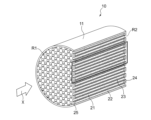
本実施形態の排ガス浄化用触媒10の例を図1ないし図4に示す。これら図面は単に、排ガス浄化用触媒の模式的な例の一つを示すものであり、何ら本発明を限定するものではない。The present invention will be described below based on its preferred embodiments, but the present invention is not limited to the following embodiments.
An example of the exhaust gas purifying
排ガス浄化用触媒10は、ガソリンエンジン、特に車両のGDIエンジンなどの内燃機関の排気経路に設けられている。排ガス浄化用触媒10は、例えばGPFとして用いられる。
The exhaust gas purifying
図1に示すように、排ガス浄化用触媒10は、いわゆるウォールフロー構造を有する基材11を有する。基材11は、種々の材料のものを用いることができ、例えば、コージェライト、炭化ケイ素(SiC)等のセラミックス等から形成された基材を好適に採用することができる。基材は、通常、図1に示すように筒状の外形を有しており、筒状外形の軸方向が排ガス流通方向Xと略一致するように、内燃機関の排気経路に配置されている。図1には、外形が円筒形状である基材が例示される。ただし、基材全体の外形については、円筒形に代えて、楕円筒形、多角筒形を採用してもよい。
As shown in FIG. 1, the exhaust gas purifying
図1に示すように、基材11は、排ガス流通方向Xに沿って延びるとともに、該流通方向Xの流入側が開口し且つ流出側が閉塞されている空間からなる流入側セル21と、該流通方向Xに沿って延びるとともに、該流通方向Xの流入側が閉塞されており且つ流出側が開口している空間からなる流出側セル22とを有している。
As shown in FIG. 1, the
流入側セル21は、排ガス流通方向Xの下流側端部R2に位置する排ガス流出側端部が封止部24で閉塞されており、上流側端部R1に位置する排ガス流入側端部が開口している。流出側セル22は、上流側端部R1に位置する排ガス流入側端部が封止部25で閉塞されており、下流側端部R2に位置する排ガス流出側端部が開口している。流入側セル21及び流出側セル22は、開口端部(以下、「開口部」ともいう)から気体や液体等の流通が可能であり、閉塞した封止部24及び封止部25では排ガスの流通が遮断されている。流入側セル21及び流出側セル22は基材11の軸方向に沿って延びる有底孔状の空間である。基材11の軸方向と直交する断面における流入側セル21及び流出側セル22の断面形状は、正方形、平行四辺形、長方形、台形などの矩形、三角形、六角形、八角形などの多角形、円形、楕円形など種々の幾何学形状であってよい。
The inflow-
流入側セル21と、隣接する流出側セル22との間には、これらを区画する多孔質の隔壁23が形成されている。この隔壁23によって、流入側セル21と流出側セル22とが仕切られている。隔壁23は、有底孔状の流入側セル21と流出側セル22の内側壁を構成している。隔壁23は、排ガス等の気体が通過可能な多孔質構造である。隔壁23の厚みとしては例えば150μm~400μmが好ましい。ここでいう厚みは、流入側セル21と流出側セル22との間の隔壁23の厚みが一定でない場合は、最も薄い部分の厚みを指す。
A
基材11は、流入側端部R1におけるひとつの流入側セル21の開口部面積と、流出側端部R2におけるひとつの流出側セル22の開口部の面積とが同じであってもよく、異なっていてもよい。ここでいう開口部の面積とは、基材11の軸方向と直交する平面の面積である。
In the
基材11には、触媒活性成分を有する触媒部が担持されている。図2に示すように、触媒部は、隔壁23の流入側セル21に臨む面のうち、排ガス流通方向X(以下、X方向ともいう)上流側に少なくとも設けられた層状の第一触媒部14(以下、第一触媒層14ともいう)と、隔壁23の流出側セル22に臨む面のうち、少なくとも排ガス流通方向Xの下流側に設けられた層状の第二触媒部15(以下、第二触媒層15ともいう)を有している。
The
本発明者は、排ガス浄化用触媒10について、細孔容積分布を測定した場合に、基材の隔壁に由来するピークの細孔容積と、基材の隔壁及び各触媒層の両者に由来するピークにおける細孔容積とを比較し、これらの比が特定の範囲内であり、且つ、各触媒層の触媒担持成分自体に由来するピークの細孔容積が一定以上であると、PM捕集性能を効果的に向上させることができることを見出した。本実施形態において触媒担持成分は金属酸化物粒子であり、その詳細は後述する。
When measuring the pore volume distribution of the exhaust
具体的には、排ガス浄化用触媒10は、log微分細孔容積分布を測定した場合に、下記式を満たす。
IB1/IA×100≧60%、IB2/IA×100≧60%、IC1/IA×100≧3%、及びIC2/IA×100≧3%。
式中、IAは、前記基材の前記隔壁を対象に測定した、細孔径10,000~100,000nmの第一範囲内で最大ピークのlog微分細孔容積であり、
IB1は、前記触媒の前記第一触媒部が設けられている部位において該第一触媒部及び前記隔壁を対象に測定した、前記第一範囲内における最大ピークのlog微分細孔容積であり、
IB2は、前記触媒の前記第二触媒部が設けられている部位において該第二触媒部及び前記隔壁を対象として測定した、前記第一範囲内における最大ピークのlog微分細孔容積であり、
IC1は、前記触媒の前記第一触媒部が設けられている部位において該第一触媒部及び前記隔壁を対象として測定した、細孔径20~500nmの第二範囲内における最大ピークのlog微分細孔容積であり、
IC2は、前記触媒の前記第二触媒部が設けられている部位において該第二触媒部及び前記隔壁を対象として測定した、前記第二範囲内における最大ピークのlog微分細孔容積である。Specifically, the exhaust
I B1 /I A ×100≧60%, I B2 /I A ×100≧60%, I C1 /I A ×100≧3%, and I C2 /I A ×100≧3%.
In the formula, I A is the log differential pore volume of the maximum peak within the first range of pore diameters of 10,000 to 100,000 nm, measured for the partition walls of the base material,
I B1 is the log differential pore volume of the maximum peak within the first range measured for the first catalyst part and the partition wall at the site where the first catalyst part of the catalyst is provided,
I B2 is the log differential pore volume of the maximum peak within the first range measured for the second catalyst part and the partition wall at the site where the second catalyst part of the catalyst is provided,
I C1 is the log differential of the maximum peak within the second range with a pore diameter of 20 to 500 nm, measured for the first catalyst part and the partition wall at the site where the first catalyst part of the catalyst is provided. is the pore volume,
I C2 is the log differential pore volume of the maximum peak within the second range measured for the second catalyst portion and the partition wall at the site where the second catalyst portion of the catalyst is provided.
上記IAは、触媒部が形成されていない基材の隔壁を測定対象とした値である。通常、GPFに用いられるウォールフロー型基材は、累積細孔容積を微分した微分細孔容積分布において細孔径10,000~100,000nmの第一範囲内に、隔壁に由来する細孔容積のピークを有する。ここで、隔壁に触媒層を設けた場合、隔壁中の細孔に浸透して細孔表面を覆うようにして形成される触媒層と、隔壁中の細孔には浸透せずに隔壁の表層部分に形成される触媒層とが存在し得る。これらの触媒層のうち、細孔に浸透した触媒層の量が増えるほど、当該基材由来の細孔径を有する細孔に由来する細孔容積は低減し、IB1/IA×100の値及びIB2/IA×100の値が低くなる。すなわち、IB1/IA×100及びIB2/IA×100の値を測定することにより、細孔に浸透した触媒層の量を推測することができる。
また、上記IC1、IC2は、各触媒層を構成する触媒担持成分(後述する金属酸化物粒子)自体が有する細孔に由来するピークの強度(細孔径20~500nmの第二範囲内における最大ピークのlog微分細孔容積)であり、通常、触媒層の形成量が増えるほど、また触媒層中の触媒担持成分の含有割合が増えるほど、IC1/IA×100及びIC2/IA×100の値が大きくなる。すなわち、IC1/IA×100及びIC2/IA×100の値を測定することにより、触媒層の形成量を推測することができる。The above I A is a value for the partition walls of the base material on which no catalyst portion is formed. Usually, the wall flow type substrate used for GPF has a pore volume derived from the partition wall within the first range of pore diameter 10,000 to 100,000 nm in the differential pore volume distribution obtained by differentiating the cumulative pore volume. have a peak. Here, when the catalyst layer is provided on the partition wall, the catalyst layer formed so as to penetrate the pores in the partition wall and cover the pore surface, and the surface layer of the partition wall without penetrating the pores in the partition wall There may be a catalyst layer formed on the part. Among these catalyst layers, as the amount of the catalyst layer permeated into the pores increases, the pore volume derived from the pores having the pore diameter derived from the substrate decreases, and the value of I B1 / IA × 100 and the value of I B2 /I A ×100 will be lower. That is, by measuring the values of I B1 /I A ×100 and I B2 /I A ×100, the amount of the catalyst layer that has permeated the pores can be estimated.
In addition, the above I C1 and I C2 are the peak intensities derived from the pores of the catalyst-supporting components (metal oxide particles described later) that constitute each catalyst layer (pore diameter within the second range of 20 to 500 nm is the log differential pore volume of the maximum peak). The value of A × 100 becomes large. That is, by measuring the values of I C1 /I A ×100 and I C2 /I A ×100, the amount of catalyst layer formed can be estimated.
本実施形態によれば、排ガス浄化用触媒10について、IB1/IA×100及びIB2/IA×100の値をそれぞれ60%以上とし、且つ、IC1/IA×100の値及びIC2/IA×100の値をそれぞれ3%以上とする。これにより、本実施形態によれば、得られる排ガス浄化用触媒10について、第一触媒層14及び第二触媒層15の形成量が一定以上であり、且つ、第一触媒層14及び第二触媒層15の基材の隔壁内における存在量が一定以下である状態に制御することができる。本発明者は、これらのパラメーターが満たされる本発明の触媒は、PM捕集に有効な細孔径を有する第一触媒層14及び第二触媒層15が隔壁の表面に適度な量で存在する構成となるため、PM捕集率が高まるものと考えている。さらに、第一触媒層14及び第二触媒層15が隔壁の表面に適度な量で存在する構成とすることにより、排ガス浄化用触媒10を通過する排ガスが第一触媒層14及び第二触媒層15と接触しやすくなり排ガス浄化性能を高めることもできる。According to the present embodiment, in the exhaust
IC1/IA×100の値は4%以上であることが、PMが第一触媒層14によっても捕集されやすくなりPM捕集率を高める点及び排ガスが第一触媒層14と接触しやすくなり排ガス浄化性能を高める点でより好ましく、4.5%以上であることがより好ましく、6%以上であることが更に好ましく、8%以上であることが特に好ましい。また、IC1/IA×100の値は、触媒層の密着性の観点から、15%以下であることが好ましく、10%以下であることがより好ましい。The fact that the value of I C1 /I A ×100 is 4% or more makes it easier for PM to be trapped by the
IC2/IA×100の値は4%以上であることが、PMが第二触媒層15によっても捕集されやすくなりPM捕集率を高める点及び排ガスが第二触媒層15と接触しやすくなり排ガス浄化性能を高める点でより好ましく、4.5%以上であることがより好ましく、6%以上であることが更に好ましく、8%以上であることが特に好ましい。IC2/IA×100の値は、触媒層の密着性の観点から、15%以下であることが好ましく、10%以下であることがより好ましい。The fact that the value of I C2 /I A ×100 is 4% or more makes it easier for PM to be trapped by the
IB1/IA×100の値は70%以上であることが、PM捕集率を高める点及び排ガス浄化性能を高める点でより好ましく、80%以上であることがより好ましく、90%以上であることが更に好ましい。The value of I B1 /I A ×100 is preferably 70% or more, more preferably 80% or more, and more preferably 90% or more in terms of increasing the PM trapping rate and exhaust gas purification performance. It is even more preferable to have
IB2/IA×100の値は60%以上であることが、PM捕集率を高める点及び排ガス浄化性能を高める点でより好ましく、80%以上であることがより好ましく、90%以上であることが更に好ましい。The value of I B2 /I A ×100 is preferably 60% or more, more preferably 80% or more, and more preferably 90% or more in terms of increasing the PM trapping rate and exhaust gas purification performance. It is even more preferable to have
更に、第一触媒層14及び第二触媒層15の形成量や細孔容積の分布を適度にバランスさせることで、排ガス浄化用触媒10全体として、圧損をより抑制しながら、PM捕集性能及び排ガス浄化性能をより高めることができるという観点から、IB1/IB2×100の値は、75%以上135%以下であることが好ましく、90%以上110%以下であることがより好ましい。Furthermore, by appropriately balancing the amount of formation of the
排ガス浄化用触媒10は、特に以下の構成を有することが好ましい。
触媒10は、流通方向Xにおいて、隔壁に第一触媒部が設けられ且つ第二触媒部が設けられていない第1の部位と、隔壁に第二触媒部が設けられ且つ前記第一触媒部が設けられていない第2の部位を有しており、IB1及びIC1は前記触媒の第1の部位の第一触媒部及び隔壁を対象に測定され、IB2及びIC2は前記触媒の第2の部位の第二触媒部及び隔壁を対象に測定され、
IC1/IA×100及びIC2/IA×100のうち少なくとも一方が4.5(%)以上である。
上記のように第1の部位と第2の部位を設けることは、例えば隔壁における流入側セルに臨む面及び流出側セルに臨む面の全体に触媒部を設ける場合に比して圧損を低減できる。本発明はこのように圧損を低減しながら、PM捕集性能を高いレベルとすることができるものである。この観点からIC1/IA×100及びIC2/IA×100の両方が4.5(%)以上であることが更に好ましい。It is particularly preferable that the exhaust
The
At least one of I C1 /I A ×100 and I C2 /I A ×100 is 4.5 (%) or more.
Providing the first portion and the second portion as described above can reduce the pressure loss compared to, for example, the case where the catalyst portion is provided on the entire surface of the partition facing the inflow side cell and the outflow side cell. . In this way, the present invention can achieve a high level of PM trapping performance while reducing pressure loss. From this point of view, both I C1 /I A ×100 and I C2 /I A ×100 are more preferably 4.5 (%) or more.
IB1及びIC1は、隔壁23における、第一触媒層14が形成され、且つ第二触媒層15が形成されていない部分(前記第1の部位)を切り出してサンプルとし、以下の方法で測定すればよい。また、IB2及びIC2は、隔壁23において第二触媒層15が形成され第一触媒層14が形成されていない部分(前記第2の部位)を切り出してサンプルとし、以下の方法で測定すればよい。IAは、触媒部が形成されていない基材11の隔壁23を切り出してサンプルとし、以下の方法で測定すればよい。あるいは、触媒部を形成後の基材11であっても、基材11について触媒部が形成されていない部分を切り出してサンプルとし、以下の方法で測定してもよい。I B1 and I C1 are obtained by cutting out a portion of the
サンプルの具体的な調製方法は、例えば以下の通りである。なお、切断の際には、基材11の軸方向と直交する断面で隔壁を切断することが好ましい。
IB1及びIC1測定用サンプルの調製:基材の上流側端部R1から全長Lに対して10%離間した箇所にて1cm3(1辺が1cmの立方体形状)を切り出す。
IB2及びIC2測定用サンプルの調製:基材の下流側端部R2から全長Lに対して10%離間した箇所にて1cm3(1辺が1cmの立方体形状)を切り出す。
サンプルの数:IB1及びIC1に対して5つ、IB2及びIC2に対して5つ。A specific sample preparation method is, for example, as follows. When cutting, it is preferable to cut the partition wall along a cross section perpendicular to the axial direction of the
Preparation of samples for I B1 and I C1 measurement: 1 cm 3 (cubic shape with 1 cm on each side) is cut out from the upstream end R1 of the base material at a distance of 10% with respect to the total length L.
Preparation of samples for I B2 and I C2 measurement: 1 cm 3 (cubic shape with 1 cm on each side) is cut out from the downstream end R2 of the base material at a distance of 10% with respect to the total length L.
Number of samples: 5 for IB1 and IC1, 5 for IB2 and IC2 .
IA測定用サンプルの調製:触媒部形成前の基材、または触媒部が形成されていない部分の基材について、上流側端部R1から全長Lに対して10%離間した箇所にて1cm3(1辺が1cmの立方体形状)を切り出したサンプルを5個、基材の下流側端部R2から全長Lに対して10%離間した箇所にて1cm3(1辺が1cmの立方体形状)を切り出したサンプルを5個、合計10個を用意する。Preparation of sample for I A measurement: 1 cm 3 at a point spaced 10% of the total length L from the upstream end R1 of the base material before formation of the catalyst part or the part of the base material where the catalyst part is not formed. Five samples (cubic shape with one side of 1 cm) were cut out, and 1 cm 3 (cubic shape with one side of 1 cm) was cut out at a distance of 10% of the total length L from the downstream end R2 of the base material. A total of 10 samples, 5 cut out, are prepared.
本実施形態において細孔容積分布とは、log微分細孔容積分布をいう。log微分細孔容積分布は、JIS R 1655:2003の水銀圧入法によって測定される。詳細には、切り出したサンプルを、必要に応じて150℃、1時間乾燥させた後、そのサンプルを室温にて細孔分布測定用水銀圧入ポロシメータを用いて細孔容積を測定する。水銀の圧入の圧力は、開始時を0.0048MPaとし、最高圧力を255.106MPaとする。これらの値を含む合計131点の圧力において細孔容積を測定する。各圧力は10秒間保持する。 In the present embodiment, the pore volume distribution refers to log differential pore volume distribution. The log differential pore volume distribution is measured by the mercury intrusion method of JIS R 1655:2003. Specifically, after drying the cut sample at 150° C. for 1 hour, the pore volume of the sample is measured at room temperature using a mercury intrusion porosimeter for pore size distribution measurement. The mercury injection pressure is 0.0048 MPa at the start and 255.106 MPa at the maximum pressure. The pore volume is measured at a total of 131 pressure points including these values. Each pressure is held for 10 seconds.
IB1及びIC1を測定することにより得られる細孔容積分布は例えば典型的には、細孔径1~1,000,000nm の測定範囲中の最大ピークが、10,000~100,000nmの第一範囲内に観察されることが好ましく、また、1~1,000nm、特に1~2,000nmの範囲中の最大ピークが、20~500nmの第二範囲内に観察されることが好ましい。更に、2,000~10,000nmの範囲にもピークが観察されていてもよい。2,000~10,000nmの範囲のピークは、主に第一触媒層14を構成するアルミナ等の金属酸化物粒子同士の隙間に由来する。The pore volume distribution obtained by measuring I B1 and I C1 , for example, typically has a maximum peak in the measurement range of 1 to 1,000,000 nm pore diameter, It is preferred to observe within one range and the maximum peak within the range of 1-1,000 nm, especially 1-2,000 nm is preferably observed within a second range of 20-500 nm. Furthermore, peaks may also be observed in the range of 2,000 to 10,000 nm. The peak in the range of 2,000 to 10,000 nm mainly originates from gaps between metal oxide particles such as alumina that constitute the
同様に、IB2及びIC2を測定することにより得られる細孔容積分布は例えば典型的には、細孔径1~1,000,000nm の測定範囲中の最大ピークが、10,000~100,000nmの第一範囲内に観察されることが好ましく、また、1~1,000nm、特に1~2,000nmの範囲中の最大ピークが、20~500nmの第二範囲内に観察されることが好ましい。更に、2,000~10,000nmの範囲にもピークが観察されていてもよい。2,000~10,000nmの範囲のピークは、主に第二触媒層15を構成するアルミナ等の金属酸化物粒子同士の隙間に由来する。Similarly, the pore volume distribution obtained by measuring I B2 and I C2 typically has a maximum peak in the measurement range of pore diameters of 1 to 1,000,000 nm, 000 nm, and the maximum peak in the range of 1-1,000 nm, especially 1-2,000 nm, is preferably observed in the second range of 20-500 nm. preferable. Furthermore, peaks may also be observed in the range of 2,000 to 10,000 nm. The peak in the range of 2,000 to 10,000 nm mainly originates from gaps between metal oxide particles such as alumina that constitute the
IB1/IA×100、IB2/IA×100、IC1/IA×100、IC2/IA×100及びIB2/IB1×100について、上記の好ましい数値を実現するためには、第一触媒層14及び第二触媒層15を構成する触媒担持成分である金属酸化物粒子の種類、粒径、第一触媒層14及び第二触媒層15のコート量等を調整すればよい。In order to achieve the above preferred values for I B1 /I A ×100, I B2 /I A ×100, I C1 /I A ×100, I C2 /I A ×100 and I B2 /I B1 ×100 can be adjusted by adjusting the type and particle size of the metal oxide particles, which are catalyst-supporting components constituting the
第一触媒層14及び第二触媒層15が含有する触媒活性成分は、同一であってもよく、それぞれ異なっていてもよい。このような触媒活性成分としては白金族金属が挙げられ、具体的には、白金(Pt)、パラジウム(Pd)、ロジウム(Rh)、ルテニウム(Ru)、イリジウム(Ir)及びオスミウム(Os)のうちのいずれか1種又は2種以上が挙げられる。排ガス浄化性能の観点から、第一触媒層14及び第二触媒層15に含まれる触媒活性成分は、それぞれ独立して、白金(Pt)、パラジウム(Pd)、ロジウム(Rh)から選ばれる少なくとも1種であることが好ましい。特に、第二触媒層15は、触媒活性成分として第一触媒層14に含まれる触媒活性成分以外の触媒活性成分を含有することが好ましい。例えば、第一触媒層14が、白金(Pt)、パラジウム(Pd)及びロジウム(Rh)から選ばれる貴金属を含有し、且つ、第二触媒層15が、白金(Pt)、パラジウム(Pd)、ロジウム(Rh)から選ばれると共に第一触媒層14の含有する貴金属以外の貴金属を含有していることが、NOx、CO、HCといった排ガス有害成分を効率的に浄化できる点で特に好ましい。特にNOx浄化性能を高める点から、第一触媒層14及び第二触媒層15の何れか一方が、ロジウム(Rh)を含有することがより好ましく、特に第一触媒層14がロジウム(Rh)を含有することが更に好ましい。The catalytically active components contained in the
更に第一触媒層14及び第二触媒層15のうち少なくとも一方が、上層及び下層からなる積層構造を有し、上層と下層とはそれぞれ同じ触媒活性成分を含んでいてもよく、異なる触媒活性成分を含んでもよいが、異なる触媒活性成分を含むことが好ましい。このようにすると一層に複数の触媒活性成分を含有した場合に起こる触媒性能の低下を回避しながら、NOx、HC、COのバランスのよい浄化を、PM捕集率を高めつつ実現することができる。また、第一触媒層14及び第二触媒層15は、このような積層構造の他に、更に別の触媒層を有していてもよい。Furthermore, at least one of the
特に図4に示す通り排ガス浄化用触媒10は第二触媒層15が下層15A及び上層15Bを有する構成を有し、これら下層15A及び上層15Bが互いに異なる触媒活性成分を有することが好ましい。
これは以下の理由による。図4に示す通り、流入側セルから流入した排ガスは上流側に位置する第一触媒層14ごと隔壁23を通過した後に第二触媒層15の表面に接触するか、或いは、第一触媒層14の表面に接触した後に第一触媒層14存在部位よりもX方向下流側で隔壁23を通過する。IB2/IA×100≧60%及びIC2/IA×100≧3%を満たす第一触媒層14及び第二触媒層15は、隔壁23表面にその構成成分が一定量存在する。このため排ガスがどのようなルートを通って隔壁23を通過したとしても、第一触媒層14及び第二触媒層15のいずれとも接触確率を高めることができる。従って、第一触媒層14及び第二触媒層15により、効率よく排ガス浄化を図ることが可能となる。特に、触媒活性成分が異なる二層を有する第二触媒層15により、より効率よく排ガス浄化を図ることが可能となる。また、IB1/IA×100≧60%及びIC1/IA×100≧3%を第一触媒層14が満たすことにより、排ガスと第一触媒層14の接触確率も高いものと考えられる。
下層15A及び上層15Bは互いに直接接触していることが好ましく、下層15Aは直接隔壁23と接触していることが好ましい。In particular, as shown in FIG. 4, the exhaust
This is for the following reasons. As shown in FIG. 4 , the exhaust gas that has flowed in from the inflow-side cell passes through the
Preferably, the
とりわけ、排ガス浄化用触媒10は、第一触媒層14がロジウム(Rh)を含有し、第二触媒層15がパラジウム(Pd)を有する下層15Aと、ロジウム(Rh)を有する上層15Bとを有すると、上記のようにIB1/IA×100≧60%、IB2/IA×100≧60%、IC1/IA×100≧3%、IC2/IA×100≧3%という構成と、第二触媒層15に触媒活性成分の異なる二層を有することによる効果と相まって、NOx浄化性能に顕著に優れた作用を発揮する。
これは、排ガス浄化用触媒10に流入する排ガスと第二触媒層下層15Aとの接触確率を高めてPdによるHC及びCO酸化を促進できると共に、排ガスと第二触媒層上層15Bとの接触確率を高めてPdによるHC及びCO酸化とRhによるNOx還元とを好適なバランスで行うことができるためと考えられる。しかも、X方向上流側の第一触媒層14及びX方向下流側の第二触媒層上層15Bとによって、触媒のX方向において、NOx還元能力の高いロジウム(Rh)を広範囲で存在させることができる。このため、排ガス浄化用触媒10中、X方向の広範囲でNOx浄化を効率的に行うことができる。第一触媒層14がロジウム(Rh)を含有し、第二触媒層15がパラジウム(Pd)を有する下層15Aと、ロジウム(Rh)を有する上層15Bとを有する排ガス浄化用触媒10は、特に高速運転時のNOx浄化性能に優れている。このため排ガス浄化用触媒10を搭載することで効果的にNOx排出量を低減させることができる。In particular, the exhaust
This increases the contact probability between the exhaust gas flowing into the exhaust
第一触媒層14中の触媒活性成分の含有割合は、排ガス浄化性能をより向上させることができるという観点より、第一触媒層14に含まれる全成分量の中で0.001質量%以上を占めることが好ましく、0.01質量%以上を占めることがより好ましく、0.05質量%以上を占めることが最も好ましい。一方、上限としては25質量%以下であることが排ガス浄化性能及びコストとのバランスの観点から好ましく、20質量%以下であることがより好ましく、15質量%以下であることが特に好ましい。
The content of the catalytically active component in the
同様に、第二触媒層15中の触媒活性成分の含有割合は、排ガス浄化性能をより向上させることができるという観点より、第二触媒層15に含まれる全成分量の中で0.001質量%以上を占めることが好ましく、0.01質量%以上を占めることがより好ましく、0.05質量%以上を占めることが最も好ましい。上限としては25質量%以下であることが排ガス浄化性能及びコストとのバランスの観点から好ましく、20質量%以下であることがより好ましく、15質量%以下であることが特に好ましい。
Similarly, the content ratio of the catalytically active component in the
排ガス浄化用触媒10の耐熱性をより一層高める点から、第一触媒層14に含まれる触媒活性成分の含有量は、基材の体積1L当たり、概ね0.01g以上が好ましく、0.05g以上がより好ましい。また第二触媒層15に含まれる触媒活性成分の含有量は、基材の体積1L当たり、概ね0.01g以上が好ましく、0.05g以上がより好ましい。
第一触媒層14及び第二触媒層15に含まれる基材体積1L当たりの触媒活性成分の含有量の上限は10g/L以下であることが好ましく、場合により5g/L以下、更に3g/L以下とすることも可能である。
ここでいう基材の体積は、基材部分だけでなく第一触媒層14及び第二触媒層15、隔壁23中の空孔、セル21及び22内の空間を含めた見掛けの体積である。From the viewpoint of further increasing the heat resistance of the exhaust
The upper limit of the content of the catalytically active component per liter of base material volume contained in the
The volume of the substrate referred to here is the apparent volume including not only the substrate portion but also the
第二触媒層15が上層15B及び下層15Aを有する場合、下層15Aに含まれる触媒活性成分の量は、上層15Bに含まれる触媒活性成分100質量部に対して、100質量部以上5000質量部以下であることが排ガス浄化性能や貴金属の総量の低減の点で好ましく、特に600質量部以上3000質量部以下であることが好ましい。特に、この範囲は、第一触媒層14がロジウム(Rh)を含有し、第二触媒層15がパラジウム(Pd)を有する下層15Aと、ロジウム(Rh)を有する上層15Bとを有する構成である場合に好ましい。
When the
触媒活性成分の量は、例えば、触媒層を全溶解して得られる溶液中の貴金属の量をICP-AESで測定することにより測定できる。
なお、基材の隔壁内に触媒層が含まれる場合には、各触媒層及び基材を全溶解して得られる溶液中の貴金属の量から、基材のみを全溶解して得られる溶液中の貴金属の量を差し引くことにより測定できる。The amount of the catalytically active component can be measured, for example, by measuring the amount of noble metal in the solution obtained by completely dissolving the catalyst layer by ICP-AES.
In addition, when the catalyst layer is included in the partition walls of the base material, the amount of precious metal in the solution obtained by dissolving all the catalyst layers and the base material can be measured by subtracting the amount of precious metal in
第一触媒層14の好ましい組成について、更に説明する。第一触媒層14には、触媒活性成分を担持する触媒担持成分を更に含有することが、触媒活性成分による排ガス浄化性能を効率よく発揮する点で好ましい。ここでいう触媒担持成分としては、金属酸化物粒子が挙げられる。金属酸化物粒子を構成する金属酸化物としては、具体的には、酸素貯蔵成分(OSC材料ともいう、OSCはoxygen storage capacityの略)である無機酸化物や、酸素貯蔵成分以外の無機酸化物が挙げられる。第一触媒層14において、酸素貯蔵成分である無機酸化物の粒子と酸素貯蔵成分以外の無機酸化物の粒子との両方が触媒活性成分を担持していることが好ましい。
なお、本明細書において金属酸化物粒子という場合、焼成により金属酸化物粒子同士が結合して焼結体となったものも含む。A preferred composition of the
In this specification, the term “metal oxide particles” also includes sintered bodies obtained by bonding metal oxide particles to each other by sintering.
本明細書中、触媒活性成分が金属酸化物粒子に「担持されている」とは、金属酸化物粒子の外表面又は細孔内表面に触媒活性成分が物理的又は化学的に吸着又は保持されている状態をいう。具体的には、金属酸化物粒子が触媒活性成分を担持していることは、例えば走査型電子顕微鏡(SEM)で観察した時の粒径の測定により確認できる。例えば、金属酸化物粒子の表面上に存在している触媒活性成分の平均粒径は当該金属酸化物粒子の平均粒径に対して、10%以下であることが好ましく、3%以下であることがより好ましく、1%以下であることが特に好ましい。ここでいう平均粒径とは、SEMで観察した時の30個以上の粒子のフェレ径の平均値である。 In the present specification, the expression that the catalytically active component is "supported" on the metal oxide particles means that the catalytically active component is physically or chemically adsorbed or retained on the outer surface or the inner surface of the pores of the metal oxide particles. It refers to the state of being Specifically, the fact that the metal oxide particles support the catalytically active component can be confirmed, for example, by measuring the particle size when observed with a scanning electron microscope (SEM). For example, the average particle size of the catalytically active component present on the surface of the metal oxide particles is preferably 10% or less, and preferably 3% or less, of the average particle size of the metal oxide particles. is more preferable, and 1% or less is particularly preferable. The average particle size as used herein is the average value of the Feret diameters of 30 or more particles observed by SEM.
酸素貯蔵成分である無機酸化物としては、多価状態を有する金属酸化物であって酸素を貯蔵する能力を有するものであればよく、例えば、CeO2やCZ材(Ce及びZrを含有するセリア-ジルコニア複合酸化物や、CeO2とZrO2との固溶体)、酸化鉄、酸化銅が挙げられる。これらに加えて、Ce以外の希土類元素の酸化物が熱的安定性の観点等から好ましく用いられる。Ce以外の希土類元素の酸化物としては、Sc2O3、Y2O3、La2O3、Pr6O11、Nd2O3、Sm2O3、Eu2O3、Gd2O3、Tb4O7、Dy2O3、Ho2O3、Er2O3、Tm2O3、Yb2O3及びLu2O3が挙げられる。
なお、CeO2-ZrO2はCeO2とZrO2との固溶体である。CeO2及びZrO2が固溶体となっていることは、X線回折装置(XRD)を用い、CeO2-ZrO2に由来する単相が形成されているか否かにより確認することができる。CeO2-ZrO2には上記のCe以外の希土類元素の酸化物が固溶していてもよい。
特に、耐熱性とOSCとのバランスの観点、及び上述したIC1/IA×100の値を上記範囲に制御しやすくなるという観点から、第一触媒層14中の好ましいCeO2の量は5~40質量%であり、更に好ましくは10~30質量%である。第一触媒層14中の好ましいZrO2の量は10~80質量%であり、更に好ましくは25~60質量%である。ここでいう好ましいCeO2及びZrO2の量は、固溶体となっているCeO2やZrO2の量をそれぞれ含むほか、セリア-ジルコニア複合酸化物を構成するCeのCeO2換算量及び該複合酸化物を構成するZrのZrO2換算量をそれぞれ含む。 The inorganic oxide that is the oxygen storage component may be any metal oxide that has a multivalent state and has the ability to store oxygen. - zirconia composite oxide, solid solution of CeO 2 and ZrO 2 ), iron oxide and copper oxide. In addition to these, oxides of rare earth elements other than Ce are preferably used from the viewpoint of thermal stability and the like. Examples of oxides of rare earth elements other than Ce include Sc2O3 , Y2O3 , La2O3 , Pr6O11 , Nd2O3 , Sm2O3 , Eu2O3 , and Gd2O3 . , Tb4O7 , Dy2O3 , Ho2O3 , Er2O3 , Tm2O3 , Yb2O3 and Lu2O3 .
CeO 2 --ZrO 2 is a solid solution of CeO 2 and ZrO 2 . A solid solution of CeO 2 and ZrO 2 can be confirmed by using an X-ray diffractometer (XRD) to see if a single phase derived from CeO 2 --ZrO 2 is formed. CeO 2 --ZrO 2 may contain an oxide of a rare earth element other than Ce as a solid solution.
In particular, from the viewpoint of the balance between heat resistance and OSC, and from the viewpoint that the value of I C1 /I A ×100 described above can be easily controlled within the above range, the preferable amount of CeO 2 in the
CeO2及びZrO2の量は、例えば、触媒層を全溶解して得られる溶液中のCe及びZrの量をICP-AESで測定し、酸化物換算することにより測定できる。
なお、基材の隔壁内に触媒層が含まれる場合には、各触媒層及び基材を全溶解して得られる溶液中のCe及びZrの量から、基材のみを全溶解して得られる溶液中のCe及びZrの量を差し引くことにより測定できる。The amounts of CeO 2 and ZrO 2 can be measured, for example, by measuring the amounts of Ce and Zr in a solution obtained by completely dissolving the catalyst layer by ICP-AES and converting them into oxides.
In addition, when the catalyst layer is included in the partition walls of the substrate, the amount of Ce and Zr in the solution obtained by completely dissolving each catalyst layer and the substrate is obtained by completely dissolving only the substrate. It can be measured by subtracting the amount of Ce and Zr in solution.
第一触媒層14に含まれうる酸素貯蔵成分以外の無機酸化物としては、酸素貯蔵成分以外の金属酸化物が挙げられ、アルミナ、シリカ、シリカ-アルミナ、チタニア、アルミノシリケート類が挙げられる。特にアルミナが耐熱性に優れるという観点で好ましく用いられる。第一触媒層14中における酸素貯蔵成分以外の無機酸化物の含有量は、上述したIC1/IA×100の値を上記範囲に制御しやすくなるという観点より、好ましくは4~50質量%であり、更に好ましくは7~30質量%である。Inorganic oxides other than the oxygen storage component that can be contained in the
アルミナの量は、例えば、触媒層を全溶解して得られる溶液中のアルミニウムの量をICP-AESで測定し、酸化物換算することにより測定できる。
なお、基材の隔壁内に触媒層が含まれる場合には、各触媒層及び基材を全溶解して得られる溶液中のAlの量から、基材のみを全溶解して得られる溶液中のAlの量を差し引くことにより測定できる。The amount of alumina can be measured, for example, by measuring the amount of aluminum in a solution obtained by completely dissolving the catalyst layer by ICP-AES and converting it into oxide.
In addition, when the catalyst layer is included in the partition walls of the base material, the amount of Al in the solution obtained by completely dissolving each catalyst layer and the base material in the solution obtained by dissolving only the base material can be measured by subtracting the amount of Al from
第二触媒層15の好ましい組成について、更に説明する。第二触媒層15には、触媒活性成分を担持する触媒担持成分を更に含有することが、触媒活性成分による排ガス浄化性能を効率よく発揮する点で好ましい。ここでいう触媒担持成分としては、第一触媒層14で列挙した金属酸化物粒子と同様に、酸素貯蔵成分である無機酸化物の粒子及び酸素貯蔵成分以外の無機酸化物の粒子が挙げられる。
A preferred composition of the
酸素貯蔵成分である無機酸化物としては、第一触媒層14で列挙した酸素貯蔵成分である無機酸化物と同様のものが挙げられる。中でも特に、セリア、あるいはセリア-ジルコニア複合酸化物を有することが、排ガス浄化用触媒のOSCが高いために好ましい。特に、耐熱性及びOSCのバランスの観点、及び上述したIC2/IA×100の値を上記範囲に制御しやすくなるという観点から、第二触媒層15中の好ましいCeO2の量は5~40質量%であり、更に好ましくは10~30質量%である。第二触媒層15中の好ましいZrO2の量は10~70質量%であり、更に好ましくは30~50質量%である。ここでいう好ましいCeO2及びZrO2の量は固溶体となっているCeO2やZrO2の量を含む。Examples of the inorganic oxide that is the oxygen storage component include the same inorganic oxides that are the oxygen storage component listed for the
第二触媒層15に含まれうる酸素貯蔵成分以外の無機酸化物としては、第一触媒層14で列挙した無機酸化物と同様のものが挙げられる。特にアルミナが、高い耐熱性を有する点から好ましい。第二触媒層15中における酸素貯蔵成分以外の無機酸化物の含有量は、上述したIC2/IA×100の値を上記範囲に制御しやすくなるという観点より、好ましくは5~50質量%であり、更に好ましくは10~30質量%である。Inorganic oxides other than the oxygen storage component that can be contained in the
PM捕集能を一層高める点や高速運転時の排ガス浄化性能を高める点から、第一触媒層14は、隔壁23の内部ではなく、主に隔壁23の表面に存在することが好ましい。第一触媒層14が隔壁23の表面に主として存在しているとは、第一触媒層14が設けられた基材11の断面において、基材11の隔壁23の表面に存在する第一触媒層14の質量が隔壁23の内部に存在する第一触媒層14の質量よりも多いことをいう。例えば第一触媒層14が設けられた隔壁の断面を、走査型電子顕微鏡(日本電子株式会社製「JEM-ARM200F」)で観察すると共に、エネルギー分散型X線分析(EDS:Energy dispersive X-ray spectrometry)で分析し、基材にのみ存在する元素(例えばSi、Mg等)と触媒層にのみ存在する元素(例えばCe、Zr等)との境界をライン分析することや、電子線マイクロアナライザ(EPMA)により分析する方法等によって、表面に主に存在していることを確認できる。同様に、第二触媒層15は、隔壁23の内部ではなく、主に隔壁23の表面に存在することが好ましい。図3及び図4では、第一触媒層14が隔壁23の表面に主として存在し、第二触媒層15が隔壁23の表面に主として存在する状態を模式的に示している。
The
本実施形態の排ガス浄化用触媒10によれば、上述したように第一触媒層14及び第二触媒層15を主に隔壁23の表面に存在させるようにし、IB1/IA×100、IB2/IA×100、IC1/IA×100及びIC2/IA×100の値をそれぞれ上記範囲に制御することにより、PM捕集に有効な第一触媒層14及び第二触媒層15が隔壁の表面に適度な量で存在する構成となるため、PM捕集率を顕著に向上させることができる。さらに、第一触媒層14及び第二触媒層15が隔壁の表面に適度な量で存在することにより、排ガス浄化用触媒10を通過する排ガスが第一触媒層14及び第二触媒層15と接触しやすくなり排ガス浄化性能を向上させることもできる。
なお、従来、触媒層を基材の隔壁の内部に形成してなる排ガス浄化用触媒が知られているが、このような触媒層が隔壁の内部に形成された構成では、触媒層によるPM捕集性能の向上効果は低いものとなってしまうため、PM捕集性能の面で不利である。しかも、触媒層が隔壁の内部に形成された構成では、排ガスが第一触媒層14及び第二触媒層15と接触し難くなってしまうため、排ガス浄化性能の面でも不利である。
これに対して、本実施形態の排ガス浄化用触媒10は、上述したように、PM捕集率を向上させることができ、さらに排ガス浄化性能も向上させることが可能なものである。According to the exhaust
Conventionally, an exhaust gas purifying catalyst is known in which a catalyst layer is formed inside the partition walls of a base material. Since the effect of improving collection performance is low, it is disadvantageous in terms of PM collection performance. Moreover, in the configuration in which the catalyst layers are formed inside the partition walls, it is difficult for the exhaust gas to come into contact with the
In contrast, as described above, the exhaust
第一触媒層14のX方向の長さL1(図2参照)は、基材11のX方向の長さL(図2参照)の10%~80%であることが、圧力損失を低減しつつ排ガス浄化性能を高める点やPMの好適な捕集性能の点で好ましく、30%~60%であることがさらに好ましい。また、第二触媒層15のX方向の長さL2(図2参照)は、基材11のX方向の長さLの30%~90%であることが、圧力損失を低減しつつ排ガス浄化性能を高める点やPMの好適な捕集性能の点で好ましく、50%~80%であることがさらに好ましい。なお、第一触媒層14は排ガス流通方向の上流側端部から形成されることが好ましく、第二触媒層15は下流側端部から形成されることが好ましい。
第一触媒層14のX方向の長さL1と、第二触媒層15のX方向の長さL2との合計長さL1+L2は、基材11のX方向の長さLを超えることが、排ガス浄化性能を高める点で好ましく、(L1+L2)/L=1.05以上であることが好ましく、1.10以上であることがより好ましい。
第一触媒層14及び第二触媒層15は図3のように一層からなるものであってもよく、図4に示すように、いずれか一方が二層以上であってもよい。例えば第二触媒層15が下層15A及び上層15Bを有するものであってもよい。この場合、下層15A及び上層15Bのいずれもが、基材11のX方向の長さLの30%~90%であることが好ましく、50%~80%であることがさらに好ましい。The X-direction length L1 (see FIG. 2) of the
The total length L1+L2 of the length L1 of the
The
第一触媒層14及び第二触媒層15の長さは以下の方法にて測定することができる。すなわち、排ガス浄化用触媒10を目視で観察し、第一触媒層14の境界と、第二触媒層15の境界とをそれぞれ特定し、第一触媒層14及び第二触媒層15をそれぞれ測長することが好ましい。この際には、例えば排ガス浄化用触媒10の任意の10ヶ所について第一触媒層14及び第二触媒層15を測長し、その平均値を、第一触媒層14及び第二触媒層15の長さとして求めることが好ましい。目視で第一触媒層14、第二触媒層15、下層15A及び/又は上層15Bに係る排ガス流通方向における境界が判断できない場合には、排ガス浄化用触媒における排ガス流通方向に沿う多数(例えば8~16か所)の位置における組成を分析し、各箇所における触媒活性成分の濃度に基づき特定することができる。各箇所における触媒活性成分の濃度は、例えば、蛍光X線分析(XRF)やICP発光分光分析(ICP-AES)により求めることができる。
The lengths of the
第一触媒層14は、基材11のX方向の上流側端部R1から下流側に延びて形成されていることが、製造容易性と排ガス浄化性能との両立の点で好ましく、同様に、第二触媒層15は、基材11のX方向の下流側端部R2から上流側に延びて形成されていることが好ましい。更に、第二触媒層15が後述するように、第二触媒層15が下層15A及び上層15Bを有する場合、下層15A及び上層15Bが基材11のX方向の下流側端部R2から上流側に延びて形成されていることが好ましい。
The
次いで、以下、本発明の排ガス浄化用触媒の好ましい製造方法について説明する。
本製造方法は、以下の(1)及び(2)の工程を有する。(1)及び(2)の工程はいずれを先に行ってもよい。
(1)触媒活性成分と、金属酸化物粒子とを含有する第一触媒層14用スラリーを、流入側セル21側の隔壁23における少なくともX方向上流側に塗布した後、乾燥又は焼成する工程。
(2)触媒活性成分と、金属酸化物粒子とを含有する第二触媒層15用スラリーを、流出側セル22側の隔壁23における少なくともX方向下流側に塗布した後、乾燥又は焼成する工程。Next, a preferred method for producing the exhaust gas purifying catalyst of the present invention will be described below.
This production method has the following steps (1) and (2). Either of the steps (1) and (2) may be performed first.
(1) A step of applying a slurry for the
(2) A step of applying a slurry for the
第二触媒層15を二層以上とする場合は(2)工程の代わりに、例えば以下の(2’-1)及び(2’-2)工程を行う。第一触媒層14を二層とする場合も同様の変更を行う。
(2’-1)触媒活性成分と、金属酸化物粒子とを含有する下層用スラリーを、流出側セル22側の隔壁23における少なくともX方向下流側に塗布して乾燥又は焼成させる。
(2’-2)触媒活性成分と、金属酸化物粒子とを含有する上層用スラリーを、流出側セル22側の隔壁23における下層用スラリー塗布箇所の少なくとも一部に塗布し、乾燥又は焼成させる。When the
(2'-1) A lower layer slurry containing a catalytically active component and metal oxide particles is applied to at least the downstream side in the X direction of the
(2′-2) An upper layer slurry containing a catalytically active component and metal oxide particles is applied to at least a portion of the lower layer slurry applied portion of the
金属酸化物粒子としては、第一触媒層14及び第二触媒層15の構成成分として上述した酸素貯蔵成分である無機酸化物の粒子及び酸素貯蔵成分以外の無機酸化物の粒子が挙げられる。(1)、(2)、(2’-1)及び(2’-2)の触媒活性成分は、硝酸塩などの水溶性塩の状態で金属酸化物粒子と混合してそれぞれ第一触媒層14用スラリー及び第二触媒層15用スラリーを得、これらを基材11に塗布した後、乾燥又は焼成を行ってもよい。あるいは、触媒活性成分は、予め金属酸化物粒子に担持させ、担持後の金属酸化物粒子をスラリーとしてもよい。触媒活性成分を予め担持する場合は金属酸化物粒子を触媒活性成分の水溶性塩の水溶液に含浸させたのち、350~550℃で焼成する方法が挙げられる。
Examples of the metal oxide particles include particles of inorganic oxides that are oxygen storage components and particles of inorganic oxides other than the oxygen storage components described above as constituent components of the
(1)の第一触媒層14用スラリー、(2)の第二触媒層15用スラリー、(2’-1)の上層用スラリー及び(2’-2)の下層用スラリーには、基材に触媒活性成分を担持した金属酸化物粒子を密着させる目的で、バインダーを含有させてもよい。バインダーとしては、例えばアルミナゾル、ジルコニアゾル、チタニアゾル、シリカゾル等が挙げられる。
In (1) the slurry for the
(1)の第一触媒層14用スラリーにおける金属酸化物粒子の粒径は、上述したIB1/IA×100及びIB2/IA×100の値をそれぞれ上記範囲に制御しやすくなるという観点より、D50が1μm以上であることが好ましく、D90が7μm以上であることが好ましく、更にD50が2μm以上であることがより好ましく、D90が15μm以上であることがより好ましい。すなわち、金属酸化物粒子のD50及びD90が大きいほどIB1及びIB2の値が大きくなる傾向にあり、一方でD50及びD90が小さいほどIB1及びIB2の値が小さくなる傾向にあるため、D50及びD90を調整することで、IB1/IA×100、IB2/IA×100及びIB2/IB1×100をより適切に制御することができるようになる。(1)の第一触媒層14用スラリーにおける金属酸化物粒子の粒径の上限は触媒活性成分の分散性を高める点から、(1)の第一触媒層14用スラリーにおける金属酸化物粒子はD50が40μm以下であることがより好ましく、D90が80μm以下であることがより好ましい。The particle size of the metal oxide particles in the slurry for the
同様に、(2)の第二触媒層15用スラリーにおける金属酸化物粒子の粒径は、上述したIB1/IA×100及びIB2/IA×100の値をそれぞれ上記範囲に制御しやすくなるという観点より、D50が1μm以上であることが好ましく、D90が7μm以上であることが好ましく、更にD50が2μm以上であることがより好ましく、D90が15μm以上であることがより好ましい。(2)の第二触媒層15用スラリーにおける金属酸化物粒子の粒径の上限は触媒活性成分の分散性を高める点から、(2)の第二触媒層15用スラリーにおける金属酸化物粒子はD50が40μm以下であることがより好ましく、D90が80μm以下であることがより好ましい。Similarly, regarding the particle size of the metal oxide particles in the slurry for the
更に、第二触媒層15が下層15A及び上層15Bを有する場合、下層15A用スラリーの金属酸化物粒子の粒径は、上述したIB1/IA×100及びIB2/IA×100の値をそれぞれ上記範囲に制御しやすくなるという観点より、D50が1μm以上であることが好ましく、D90が7μm以上であることが好ましく、更にD50が2μm以上であることがより好ましく、D90が15μm以上であることがより好ましい。触媒活性成分の分散性を高める点から、下層15A用スラリーの金属酸化物粒子はD50が40μm以下であることがより好ましく、D90が80μm以下であることがより好ましい。Furthermore, when the
同様に、第二触媒層15の上層15B用スラリーの金属酸化物粒子の粒径は、上述したIB1/IA×100及びIB2/IA×100の値をそれぞれ上記範囲に制御しやすくなるという観点より、D50が1μm以上であることがより好ましく、D90が7μm以上であることがより好ましく、更にD50が2μm以上であることがより好ましく、D90が15μm以上であることがより好ましい。触媒活性成分の分散性を高める点から、上層15B用スラリーの金属酸化物粒子はD50が40μm以下であることがより好ましく、D90が80μm以下であることがより好ましい。Similarly, the particle size of the metal oxide particles in the slurry for the
なおここでいう金属酸化物粒子の粒径とは触媒活性成分を担持する成分の粒径を意味し、スラリーがバインダーとしてアルミナゾル、ジルコニアゾル、チタニアゾル、シリカゾル等を含む場合、それらのゾルを含んだ粒径を示すものである。 The particle size of the metal oxide particles as used herein means the particle size of the component that supports the catalytically active component. It shows the particle size.
金属酸化物粒子のD50及びD90は、触媒活性成分を担持した状態の粒径であっても、触媒活性成分担持前の状態の粒径であってもよく、触媒活性成分を担持後及び担持前の何れかの状態において、上記の好ましい下限以上或いは上限以下であればよい。
また、金属酸化物粒子のD50及びD90は、例えば以下のように測定することができる。すなわち、レーザー回折粒子径分布測定装置用自動試料供給機(マイクロトラック・ベル社製「Microtorac SDC」)を用い、金属酸化物粒子を水性溶媒に投入し、40%の流速中、40Wの超音波を360秒間照射した後、レーザー回折散乱式粒度分布計(マイクロトラック・ベル社製「マイクロトラックMT3300EXII」)を用いて測定する。測定条件は、粒子屈折率1.5、粒子形状真球形、溶媒屈折率1.3、セットゼロ30秒、測定時間30秒、2回測定の平均値として求める。水性溶媒としては純水を用いる。The D50 and D90 of the metal oxide particles may be the particle size in the state in which the catalytically active component is supported, or the particle size in the state before the catalytically active component is supported. In any one of the states, it is sufficient that it is equal to or more than the above preferable lower limit or equal to or less than the upper limit.
Moreover, D50 and D90 of metal oxide particles can be measured, for example, as follows. That is, using an automatic sample feeder for a laser diffraction particle size distribution analyzer ("Microtorac SDC" manufactured by Microtrac Bell), metal oxide particles are put into an aqueous solvent, and 40 W ultrasonic waves are applied at a flow rate of 40%. is irradiated for 360 seconds, and then measured using a laser diffraction scattering particle size distribution meter (“Microtrac MT3300EXII” manufactured by Microtrac Bell). Measurement conditions are as follows: particle refractive index 1.5, particle shape true sphere, solvent refractive index 1.3, set zero 30 seconds, measurement time 30 seconds, average value of two measurements. Pure water is used as the aqueous solvent.
(1)の第一触媒層14用スラリー及び(2)の第二触媒層15用スラリー、(2’-1)の上層用スラリー及び(2’-2)の下層用スラリーは、造孔材を含有させて、各層の細孔容積を調整してもよい。造孔材としては、例えば架橋ポリ(メタ)アクリル酸メチル粒子、架橋ポリ(メタ)アクリル酸ブチル粒子、架橋ポリスチレン粒子、架橋ポリアクリル酸エステル粒子などを用いることができる。
なお、スラリー中の造孔材の含有割合は、第一触媒層14用スラリー、第二触媒層15用スラリー、上層用スラリー及び下層用スラリーについて、それぞれ、スラリー中の固形分に対して、1~40質量%が好ましく、5~30質量%がより好ましい。造孔材の含有割合を上記範囲に制御することにより、第一触媒層14及び第二触媒層15中に、適度な数及び大きさの細孔が形成され、これにより、第一触媒層14及び第二触媒層15によるPM捕集性能及び排ガス浄化性能をより向上させることができる。The slurry for the first catalyst layer 14 (1), the slurry for the second catalyst layer 15 (2), the upper layer slurry (2′-1) and the lower layer slurry (2′-2) are pore formers. may be included to adjust the pore volume of each layer. Examples of the pore-forming material that can be used include crosslinked polymethyl(meth)acrylate particles, crosslinked polybutyl(meth)acrylate particles, crosslinked polystyrene particles, crosslinked polyacrylate particles, and the like.
The content ratio of the pore-forming material in the slurry is 1 to the solid content in the slurry for each of the slurry for the
(1)の第一触媒層14用スラリーを基材11に塗布するためには、当該スラリーに基材11の排ガス流通方向上流側を浸漬させる方法が挙げられる。当該浸漬と同時にスラリーを下流側から吸引してもよい。このような方法により、第一触媒層14用スラリーが基材11のX方向上流側の流入側セル開口部を通じて、当該上流側における、隔壁23の流入側セルに臨む面に塗工される。上述した金属酸化物粒子の粒径により、第一触媒層14を構成する金属酸化物はその少なくとも一部が隔壁23表面に位置することとなる。
In order to apply the slurry for the
(2)第二触媒層15用スラリー、(2’-1)の上層用スラリー及び(2’-2)の下層用スラリーを基材11に塗工するためには、これらのスラリーに基材11の排ガス流通方向下流側を浸漬させる方法が挙げられる。当該浸漬と同時にスラリーを上流側から吸引してもよい。このような方法により、第二触媒層15用スラリーが基材11のX方向下流側の流出側セル開口部を通じて、当該下流側における、隔壁23の流出側セルに臨む面に塗工される。上述した金属酸化物粒子の粒径により、第二触媒層15を構成する金属酸化物はその少なくとも一部が隔壁23表面に位置することとなる。
(2) In order to coat the
(1)、(2)、(2’-1)及び(2’-2)のスラリーの乾燥温度は、いずれも40~120℃が好ましく、焼成温度は、いずれも350~550℃が好ましい。 The drying temperature of the slurries (1), (2), (2'-1) and (2'-2) is preferably 40 to 120°C, and the firing temperature is preferably 350 to 550°C.
更に本実施形態の排ガス浄化用触媒10においては、第一触媒層14のコート量は、コートする触媒活性成分の量に応じて制御すればよいが、上述したIC1/IA×100及びIC2/IA×100の値を上記範囲に制御しやすくなるという観点より、乾燥後の重量で、基材の体積1Lあたり10g以上であることが好ましく、特に20g以上であることがより好ましい。第一触媒層14のコート量は、乾燥後の重量で、基材の体積1Lあたり60g以下であることが圧力損失の低減の観点、及び、高速運転時の排ガス浄化性能の向上などの点で好ましく、50g以下であることがより好ましい。
また、第二触媒層15のコート量は、コートする触媒活性成分の量に応じて制御すればよいが、上述したIC1/IA×100及びIC2/IA×100の値を上記範囲に制御しやすくなるという観点より、乾燥後の重量で、基材の体積1Lあたり20g以上であることが好ましく、30g以上であることがより好ましい。圧力損失の低減のために、第二触媒層15のコート量は、乾燥後の重量で、基材の体積1Lあたり80g以下であることが好ましく、60g以下であることがより好ましい。また、下層15A及び上層15Bのコート量の質量比は例えば好ましくは100:10~200、より好ましくは100:50~150であることが、排ガス浄化性能がより向上するという観点から好ましい。Furthermore, in the
Further, the coating amount of the
上記の製法にて得られた排ガス浄化用触媒は、図2に示すように、基材11の流入側セル21から排ガスが流入する。流入側セル21から流入した排ガスは、多孔質の隔壁23を通過して流出側セル22に到達する。図2においては、流入側セル21から流入した排ガスが隔壁23を通過して流出側セル22に到達するルートを矢印で示している。このとき、隔壁23は多孔質構造を有しているので、排ガスがこの隔壁23を通過する間に、PMが隔壁23の表面や隔壁23の内部の細孔内に捕集される。また、隔壁23には、第一触媒層14及び第二触媒層15が設けられているので、排ガスが隔壁23の内部及び表面を通過する間に、第一触媒層14及び第二触媒層15の触媒活性成分と接触して、排ガス中の有害成分が浄化される。隔壁23を通過して流出側セル22に到達した排ガスは、排ガス流出側の開口から基材11に流入した後、排ガス浄化用触媒10の外部へと排出される。
As shown in FIG. 2, exhaust gas flows into the exhaust gas purifying catalyst obtained by the above manufacturing method from the inflow-
このように製造された排ガス浄化用触媒10は、そのPM捕集性能と排ガス浄化性能を活かし、ガソリンエンジンなど化石燃料を動力源とする内燃機関の排ガス浄化用触媒として、種々の用途に用いることができる。また、本実施形態によれば、このような排ガス浄化用触媒10を用いた排ガス浄化方法も提供することができる。例えば、排ガス浄化用触媒10を、ガソリンエンジン、特に車両のGDIエンジンなどの内燃機関の排気経路に設けて、GPF等として用いることで、ガソリンエンジンからの排ガスを良好に浄化することが可能となる。
The exhaust
以下、実施例により本発明を更に詳細に説明する。しかしながら本発明の範囲は、かかる実施例に制限されない。なお、乾燥及び焼成はすべて大気中で行った。 EXAMPLES The present invention will be described in more detail below with reference to examples. However, the scope of the invention is not limited to such examples. All drying and firing were performed in the atmosphere.
<実施例1>
〔1.スラリーの調製〕
(第1のスラリー)
D50=8μm、D90=22μmのCeO2-ZrO2固溶体粉末(CeO2-ZrO2固溶体中にCeO215質量%、ZrO270質量%、Ce以外の希土類元素の酸化物15質量%を含有)及びD50=8μm、D90=22μmのアルミナ粉末を用意した。CeO2-ZrO2固溶体粉末とアルミナ粉末とを質量比84:8で混合し、硝酸ロジウム水溶液中に含浸させた。
次いで、この混合液と、該混合液の固形分に対して25質量%の造孔材(架橋ポリ(メタ)アクリル酸メチル粒子)と、該混合液の固形分に対して3質量%のアルミナゾルと、該混合液の固形分に対して5質量%のジルコニアゾルと、液媒として水と、を混合して、第1のスラリーを調製した。この第1のスラリーの造孔材を除く固形分中、硝酸ロジウムはロジウム金属換算で0.3質量%含まれている。<Example 1>
[1. Preparation of slurry]
(First slurry)
CeO 2 —ZrO 2 solid solution powder with D50=8 μm and D90=22 μm (CeO 2 —ZrO 2 solid solution containing 15% by mass of CeO 2 , 70% by mass of ZrO 2 , and 15% by mass of oxides of rare earth elements other than Ce) And alumina powder with D50=8 μm and D90=22 μm was prepared. CeO 2 —ZrO 2 solid solution powder and alumina powder were mixed at a mass ratio of 84:8 and impregnated in an aqueous rhodium nitrate solution.
Next, this mixture, 25% by mass of a pore-forming material (crosslinked poly(meth)methyl acrylate particles) based on the solid content of the mixture, and 3% by mass of alumina sol based on the solid content of the mixture A first slurry was prepared by mixing 5% by mass of zirconia sol with respect to the solid content of the mixed liquid and water as a liquid medium. The solid content of the first slurry excluding the pore-forming material contained 0.3% by mass of rhodium nitrate in terms of rhodium metal.
(第2のスラリー)
D50=8μm、D90=22μmのCeO2-ZrO2固溶体粉末(CeO2-ZrO2固溶体中にCeO240質量%、ZrO250質量%、Ce以外の希土類元素の酸化物10質量%を含有)、D50=8μm、D90=22μmのアルミナ粉末を質量比60:22で混合し、硝酸パラジウム水溶液中に含浸させた。
次いで、この混合液と、該混合液の固形分に対して25質量%の造孔材(架橋ポリ(メタ)アクリル酸メチル粒子)と、該混合液の固形分に対して3質量%のアルミナゾルと、該混合液の固形分に対して3質量%のジルコニアゾルと、液媒として水と、を混合して、第2のスラリーを調製した。この第2のスラリーの造孔材を除く固形分中、硝酸パラジウムはパラジウム金属換算で3.8質量%含まれている。(Second slurry)
CeO 2 —ZrO 2 solid solution powder with D50=8 μm and D90=22 μm (CeO 2 —ZrO 2 solid solution contains 40% by mass of CeO 2 , 50% by mass of ZrO 2 , and 10% by mass of oxides of rare earth elements other than Ce) , D50=8 μm and D90=22 μm were mixed at a mass ratio of 60:22 and impregnated in an aqueous palladium nitrate solution.
Next, this mixture, 25% by mass of a pore-forming material (crosslinked poly(meth)methyl acrylate particles) based on the solid content of the mixture, and 3% by mass of alumina sol based on the solid content of the mixture A second slurry was prepared by mixing 3% by mass of zirconia sol with respect to the solid content of the mixed liquid and water as a liquid medium. The solid content of the second slurry excluding the pore-forming material contained 3.8% by mass of palladium nitrate in terms of palladium metal.
〔2.触媒層の形成〕
基材11として、図1に示す構造を有し、厚さが200μmの隔壁で区画された軸方向に延びるセルを、軸方向と直交する面において、300セル/inch2有し、体積が1.4Lである基材11を用いた。基材11について、後述する方法でlog微分細孔容積分布を測定したところ、細孔容積のピーク位置は細孔径18,120nmであり、当該ピーク位置のlog微分細孔容積はIA=1.84cm3/gであった。基材11は、流入側端面におけるひとつの流入側セル21の開口部の面積と、流出側端面におけるひとつの流出側セル22の開口部の面積とが概ね同じであった。[2. Formation of catalyst layer]
The
第1のスラリー中に基材11の排ガス流通方向の上流側端部を浸漬し、下流側から吸引した後に70℃で10分乾燥させた。
The upstream end of the
乾燥後の基材11の排ガス流通方向の下流側端部を、第2のスラリー中に浸漬し、上流側から吸引した後に70℃で10分乾燥させた。続いて第2のスラリー乾燥後の基材11における排ガス流通方向の下流側端部を今度は第1のスラリーに浸漬し、再度上流側から吸引した後に70℃で10分乾燥させて下層に上層を積層させた。
The downstream end of the dried
その後、450℃、1時間で焼成した。これにより、実施例1の排ガス浄化用触媒10を得た。得られた第一触媒層14は、一層からなる。一方、第二触媒層15は、二層からなる。
After that, it was baked at 450° C. for 1 hour. Thus, an exhaust
また、実施例1の排ガス浄化用触媒において、排ガス浄化用触媒10の第一触媒層14は、排ガス流通方向Xの上流側端部R1から下流側に全長Lの40%までの範囲にかけて、流入側セル21側の隔壁23の表面に形成されており、基材の体積に対するコート量は乾燥後の重量で21.6g/Lであった。第一触媒層14に含まれたRh量は、基材の体積に対して0.065g/Lであった。
排ガス浄化用触媒10の第二触媒層15における下層15A及び上層15Bは、排ガス流通方向Xの下流側端部R2から上流側に全長Lの70%までの範囲にかけて、流出側セル22側の隔壁23の表面に形成されていた。基材の体積に対するコート量は乾燥後の重量で下層15Aが26.9g/L、上層15Bが12.6g/Lであった。第二触媒層の下層15Aに含まれたPd量は基材の体積に対して1.022/Lであり、第二触媒層の上層15Bに含まれたRh量は基材の体積に対して0.038g/Lであった。In addition, in the exhaust gas purifying catalyst of Example 1, the
The
<実施例2>
第一触媒層14のコート量を26.1g/Lとし、第二触媒層15の上層15Bのコート量を8.1g/Lとした。それらの点以外は実施例1と同様にして排ガス浄化用触媒を得た。<Example 2>
The coating amount of the
<実施例3>
第一触媒層14のコート量を17.1g/Lとし、第二触媒層15の上層15Bのコート量を17.1g/Lとした。それらの点以外は実施例1と同様にして排ガス浄化用触媒を得た。<Example 3>
The coating amount of the
<実施例4>
基材11として、図1に示す構造を有し、厚さが250μmのセル隔壁で区画された軸方向に延びるセルを、軸方向と直交する面において、300セル/inch2有し、体積が1.4Lであり、平均細孔径が実施例1で用いたものとは異なる基材11を用いた。基材11について後述する方法でlog微分細孔容積分布を測定したところ、細孔容積のピーク位置は細孔径16,469nmであり、当該ピーク位置のlog微分細孔容積はIA=1.72cm3/gであった。
また第1のスラリー及び第2のスラリーのいずれにも造孔材を添加しなかった。
更に、第一触媒層14のコート量を25.1g/Lとし、第二触媒層15の下層15Aのコート量を23.9g/Lとし、上層15Bのコート量を12.1g/Lとした。それらの点以外は実施例1と同様にして排ガス浄化用触媒を得た。<Example 4>
The
Also, no pore former was added to either the first slurry or the second slurry.
Further, the coating amount of the
<実施例5>
第1のスラリーの造孔材の量を、CeO2-ZrO2固溶体粉末及びアルミナ粉末を含む混合溶液の固形分に対して10質量%とするとともに、第2のスラリーの造孔材の量を、CeO2-ZrO2固溶体粉末及びアルミナ粉末を含む混合溶液の固形分に対して25質量%とした。
それらの点以外は、実施例4と同様とした。<Example 5>
The amount of the pore-forming material in the first slurry is set to 10% by mass with respect to the solid content of the mixed solution containing the CeO 2 —ZrO 2 solid solution powder and the alumina powder, and the amount of the pore-forming material in the second slurry is set to , CeO 2 —ZrO 2 solid solution powder and alumina powder in a solid content of 25 mass %.
Except for these points, the procedure was the same as in Example 4.
<実施例6>
第1のスラリー及び第2のスラリーにおいて、それぞれ、粒径がD50=2μm、D90=7μmのCeO2-ZrO2固溶体粉末及び粒径がD50=2μm、D90=7μmのアルミナ粉末を用いた。
それらの点以外は、実施例5と同様とした。<Example 6>
In the first slurry and the second slurry, a CeO 2 —ZrO 2 solid solution powder with a particle size of D50=2 μm and D90=7 μm and an alumina powder with a particle size of D50=2 μm and D90=7 μm were used, respectively.
Except for these points, the procedure was the same as in Example 5.
<実施例7>
第1のスラリー及び第2のスラリーにおいて、それぞれ、粒径がD50=14μm、D90=42μmのCeO2-ZrO2固溶体粉末及び粒径がD50=14μm、D90=42μmのアルミナ粉末を用いた。
それらの点以外は、実施例5と同様とした。<Example 7>
In the first slurry and the second slurry, a CeO 2 -ZrO 2 solid solution powder with a particle size of D50 = 14 µm and D90 = 42 µm and an alumina powder with a particle size of D50 = 14 µm and D90 = 42 µm were used, respectively.
Except for these points, the procedure was the same as in Example 5.
<実施例8>
第1のスラリーの造孔材の量を、CeO2-ZrO2固溶体粉末及びアルミナ粉末を含む混合溶液の固形分に対して10質量%とするとともに、第2のスラリーの造孔材の量を、CeO2-ZrO2固溶体粉末及びアルミナ粉末を含む混合溶液の固形分に対して10質量%とした。
第1のスラリーにおいて硝酸ロジウムではなく、硝酸パラジウムを用いた。
第2のスラリーにおいて硝酸パラジウムではなく、硝酸ロジウムを用いた。
第二触媒層15の上層15Bを設けず、第一触媒層14のコート量を25.2g/Lとし、第2のスラリーからなる第二触媒層15のコート量を45.9g/Lとした。
それらの点以外は、実施例1と同様とした。なお、得られた第一触媒層14に含まれたPd量は、基材の体積に対して0.075g/Lであった。また、第二触媒層15に含まれたRh量は、基材の体積に対して1.744g/Lであった。<Example 8>
The amount of the pore-forming material in the first slurry is set to 10% by mass with respect to the solid content of the mixed solution containing the CeO 2 —ZrO 2 solid solution powder and the alumina powder, and the amount of the pore-forming material in the second slurry is set to , CeO 2 —ZrO 2 solid solution powder and alumina powder in a solid content of 10 mass %.
Palladium nitrate was used instead of rhodium nitrate in the first slurry.
Rhodium nitrate was used instead of palladium nitrate in the second slurry.
The
Except for these points, the procedure was the same as in Example 1. The amount of Pd contained in the obtained
<比較例1>
第1のスラリーの造孔材の量を、CeO2-ZrO2固溶体粉末及びアルミナ粉末を含む混合溶液の固形分に対して25質量%とした。一方、第2のスラリーに造孔材を添加しなかった。
第1のスラリーにおけるCeO2-ZrO2固溶体粉末とアルミナ粉末の質量比を3:1とし、第2のスラリーにおけるCeO2-ZrO2固溶体粉末とアルミナ粉末の質量比を7:1とした。
第一触媒層14のコート量を10.0g/Lとし、第2のスラリーからなる第二触媒層15のコート量を50.0g/Lとした。
それらの点以外は、実施例8と同様とした。なお、得られた第一触媒層14に含まれたPd量は、基材の体積に対して0.030g/Lであった。また、第二触媒層15に含まれたRh量は、基材の体積に対して1.9g/Lであった。<Comparative Example 1>
The amount of the pore-forming material in the first slurry was 25% by mass with respect to the solid content of the mixed solution containing the CeO 2 --ZrO 2 solid solution powder and alumina powder. On the other hand, no pore former was added to the second slurry.
The mass ratio of the CeO 2 —ZrO 2 solid solution powder and the alumina powder in the first slurry was 3:1, and the mass ratio of the CeO 2 —ZrO 2 solid solution powder and the alumina powder in the second slurry was 7:1.
The coating amount of the
Except for these points, it was the same as Example 8. The amount of Pd contained in the obtained
<比較例2>
第1のスラリーに造孔材を添加しなかった。
第1のスラリーにおいて、CeO2-ZrO2固溶体粉末とアルミナ粉末の質量比を1:1とした。
それらの点以外は、比較例1と同様とした。<Comparative Example 2>
No pore former was added to the first slurry.
In the first slurry, the mass ratio of the CeO 2 --ZrO 2 solid solution powder and the alumina powder was 1:1.
Except for these points, it was the same as Comparative Example 1.
[細孔容積の測定]
実施例及び比較例の各触媒を、上記の方法にて、排ガス浄化用触媒10における上流側端部R1から下流側に基材11の全長Lの10%離間した位置における隔壁23の一部を上流側サンプルとして1cm3(1辺が1cmの立方体形状)切り出した。同様に、下流側端部R2から上流側に全長Lの10%離間した位置における隔壁23の一部を下流側サンプルとして1cm3(1辺が1cmの立方体形状)切り出した。
そして、得られた結果から、IA、IB1、IB2、IC1及びIC2を求め、IB1/IA×100(%)、IB2/IA×100(%)、IC1/IA×100(%)及びIC2/IA×100(%)を算出した。得られた値を表1にそれぞれ示す。
なお、具体的な測定条件は以下の通りとした。
[排ガス浄化用触媒におけるlog微分細孔容積分布の測定]
測定装置としては、株式会社島津製作所製自動ポロシメータ「オートポアIV9520」を用いて、下記条件・手順で測定を行った。
(測定条件)
測定環境:25℃
測定セル:試料室体積 3cm3、圧入体積 0.39cm3
測定範囲:0.0048MPa から 255.106MPa まで
測定点:131点(細孔径を対数でとったときに等間隔になるように点を刻んだ)
圧入体積:25%以上80%以下になるように調節した。
(低圧パラメーター)
排気圧力:50μmHg
排気時間:5.0min
水銀注入圧力:0.0034MPa
平衡時間:10sec
(高圧パラメーター)
平衡時間:10sec
(水銀パラメーター)
前進接触角:130.0degrees
後退接触角:130.0degrees
表面張力:485.0mN/m(485.0dyne/cm)
水銀密度:13.5335g/mL
(測定手順)
(1)低圧部で0.0048MPaから0.2068MPa以下の範囲で46点測定。
(2)高圧部で0.2241MPaから255.1060MPa以下の範囲で85点測定。
(3)水銀注入圧力及び水銀注入量から、細孔容積分布を算出する。
なお、前記(1)、(2)、(3)は、装置付属のソフトウエアにて、自動で行った。その他の条件はJIS R 1655:2003に準じた。[Measurement of pore volume]
Each of the catalysts of the examples and the comparative examples was subjected to the above-described method so that part of the
Then, from the obtained results, I A , I B1 , I B2 , I C1 and I C2 are obtained, and I B1 /I A ×100 (%), I B2 / IA ×100 (%), I C1 / I A ×100 (%) and I C2 /I A ×100 (%) were calculated. The obtained values are shown in Table 1, respectively.
In addition, the specific measurement conditions were as follows.
[Measurement of log differential pore volume distribution in exhaust gas purification catalyst]
As a measuring device, an automatic porosimeter "Autopore IV9520" manufactured by Shimadzu Corporation was used, and the measurement was performed under the following conditions and procedures.
(Measurement condition)
Measurement environment: 25°C
Measurement cell: sample chamber volume 3 cm 3 , injection volume 0.39 cm 3
Measurement range: 0.0048 MPa to 255.106 MPa Measurement points: 131 points (points were carved at even intervals when the pore diameter was taken logarithmically)
Injection volume: adjusted to be 25% or more and 80% or less.
(low pressure parameter)
Exhaust pressure: 50 μmHg
Exhaust time: 5.0min
Mercury injection pressure: 0.0034 MPa
Equilibration time: 10 sec
(high pressure parameter)
Equilibration time: 10 sec
(mercury parameter)
Advancing contact angle: 130.0 degrees
Receding contact angle: 130.0 degrees
Surface tension: 485.0 mN/m (485.0 dyne/cm)
Mercury density: 13.5335g/mL
(Measurement procedure)
(1) Measurement at 46 points in the range from 0.0048 MPa to 0.2068 MPa or less at the low pressure part.
(2) Measurement at 85 points in the range from 0.2241 MPa to 255.1060 MPa or less at the high pressure section.
(3) Calculate the pore volume distribution from the mercury injection pressure and the mercury injection amount.
The above (1), (2), and (3) were automatically performed using the software attached to the apparatus. Other conditions conformed to JIS R 1655:2003.
なお、各実施例において、IB1及びI C1測定時における第一触媒層14及び隔壁23を対象に測定したlog微分細孔容積分布には、細孔径1~1,000,000nm の測定範囲中の最大ピークが、10,000~100,000nmの第一範囲に観察された。また1~2,000nmの範囲中の最大ピークが、20~500nmの第二範囲に観察された。更に、2,000~10,000nmの範囲にもピークが観察された。同様に、各実施例において、IB2及びI C2測定時における第二触媒層15及び隔壁23を対象に測定したlog微分細孔容積分布には、細孔径1~1,000,000nmの測定範囲中の最大ピークが、10,000~100,000nmの第一範囲に観察された。また1~2,000nmの範囲中の最大ピークが、20~500nmの第二範囲に観察された。更に、2,000~10,000nmの範囲にもピークが観察された。In each example, the log differential pore volume distribution measured for the
[PM捕集性能]
排ガス浄化用触媒10を用いた車両を、国際調和排ガス試験モード(WLTC)の運転条件に従って運転した。運転開始から、589秒までの低速運転時、運転開始589秒から1022秒までの中速運転時、運転開始1022秒から1477秒までの高速運転時、運転開始から1477秒から1800秒までの超高速運転時のそれぞれにおける排ガス浄化用触媒10を通過した排ガス中のPM粒子数(PNcat)を測定した。さらに、エンジンから直接排出されるPM粒子数(PNall)を測定し、下記式によりPM捕集率を求めた。結果を表1に示す。
PM捕集率(%)=100-(PNcat/PNall)×100
(PM捕集率測定条件)
・評価車両:1.5L直噴ターボエンジン
・使用ガソリン:認証試験用燃料
・PM測定装置:堀場製作所社製[PM collection performance]
A vehicle using the exhaust
PM collection rate (%) = 100-(PN cat /PN all ) × 100
(PM collection rate measurement conditions)
・Evaluation vehicle: 1.5L direct-injection turbo engine ・Gasoline used: Fuel for certification test ・PM measuring device: Horiba Ltd.
[NOx排出量の測定]
実施例及び比較例の排ガス浄化用触媒を、エンジンの排気経路に配置し、10~20万キロ走行を想定した劣化処理として、次のような耐久条件を課した。
(耐久条件)
・耐久用エンジン:乗用NA 2L ガソリンエンジン
・使用ガソリン:市販レギュラーガソリン
・耐久温度・時間:900℃、100hr[Measurement of NOx emissions]
The exhaust gas purifying catalysts of the examples and comparative examples were placed in the exhaust path of the engine, and the following durability conditions were imposed as deterioration treatment assuming running 100,000 to 200,000 kilometers.
(durability condition)
・Durability engine: Passenger NA 2L gasoline engine ・Gasoline used: Commercially available regular gasoline ・Endurance temperature/time: 900℃, 100hr
上記条件にて耐久試験を行った後に、耐久後の排ガス浄化用触媒を下記車両に設置した。次いで、該車両を、国際調和排ガス試験モード(WLTC)の運転条件に従って運転した。運転開始から、589秒までの低速運転時、運転開始589秒から1022秒までの中速運転時、運転開始1022秒から1477秒までの高速運転時、運転開始から1477秒から1800秒までの超高速運転時のそれぞれにおける排ガス浄化用触媒10を通過した排ガス中の窒素酸化物(NOx)の排出量(エミッション値)を測定した。結果を表1に示す。なお、NOx排出量の測定は、実施例1~4,8及び比較例1,2についてのみ行った。
(浄化率測定条件)
・評価車両:1.5L直噴ターボエンジン
・使用ガソリン:認証試験用燃料
・排ガス測定装置:堀場製作所社製After the endurance test was conducted under the above conditions, the exhaust gas purifying catalyst after endurance was installed in the following vehicle. The vehicle was then driven according to the operating conditions of the International Harmonized Emission Test Mode (WLTC). During low speed operation from 589 seconds to 1022 seconds from the start of operation, during high speed operation from 1022 seconds to 1477 seconds from the start of operation, at high speed from 1477 seconds to 1800 seconds from the start of operation The emission amount (emission value) of nitrogen oxides (NO x ) in the exhaust gas that passed through the exhaust
(Conditions for purification rate measurement)
・Evaluation vehicle: 1.5L direct-injection turbo engine ・Gasoline used: Fuel for certification test ・Exhaust gas measurement device: Horiba Ltd.

表1に示す通り、IB1/IA×100≧60%、IB2/IA×100≧60%、IC1/IA×100≧3%、IC2/IA×100≧3%を満たす各実施例は、PM捕集率が高い。これに対し、IB2/IA×100≧60%或いはIC1/IA×100≧3%を満たさない比較例1及び2はPM捕集率に劣る。また、第一触媒層14にPdを含有させ、第二触媒層15にRhを含有させ、第二触媒層15を一層とする実施例8及び比較例1はいずれもNOx排出量が比較的多かった(9mg/km超)に比して、第一触媒層14にRhを含有させ、第二触媒層15の下層にPdを、上層にRhを含有させる実施例1~4の構成により、NOx排出量を8.3mg/km以下まで低減させることができ、NOx浄化性能を向上させることができることも判る。また、各実施例で用いた排ガス浄化用触媒は、圧損の低いものであった。As shown in Table 1, I B1 /I A ×100≧60%, I B2 /I A ×100≧60%, I C1 /I A ×100≧3%, and I C2 / IA ×100≧3%. Each satisfying example has a high PM capture rate. On the other hand, Comparative Examples 1 and 2, which do not satisfy I B2 /I A ×100≧60% or I C1 /I A ×100≧3%, are inferior in PM trapping efficiency. In addition, both Example 8 and Comparative Example 1, in which the
10 排ガス浄化用触媒
11 基材
14 第一触媒層
15 第二触媒層
21 流入側セル
22 流出側セル
23 隔壁REFERENCE SIGNS
Claims (5)
前記基材は、
排ガス流通方向の流入側が開口し且つ流出側が閉塞されている空間からなる流入側セルと、
排ガス流通方向の流入側が閉塞されており且つ流出側が開口している空間からなる流出側セルと、
該流入側セルと該流出側セルとを隔てる多孔質の隔壁とを有し、
前記触媒部は、
前記隔壁における前記流入側セルに臨む面のうち、前記排ガス流通方向の上流側の少なくとも一部に設けられた第一触媒部と、
前記隔壁における前記流出側セルに臨む面のうち、前記排ガス流通方向の下流側の少なくとも一部に設けられた第二触媒部とを有する排ガス浄化用触媒であって、
前記触媒は、前記排ガス流通方向において、前記隔壁に前記第一触媒部が設けられ且つ前記第二触媒部が設けられていない第1の部位と、前記隔壁に前記第二触媒部が設けられ且つ前記第一触媒部が設けられていない第2の部位を有しており、
前記基材及び前記触媒について測定した細孔径に対する細孔容積の分布が、下記式を満たす、排ガス浄化用触媒。
IB1/IA×100≧60(%)、IB2/IA×100≧60(%)、IC1/IA×100≧3(%)及びIC2/IA×100≧3(%)。
ただし、IC1/IA×100及びIC2/IA×100のうち少なくとも一方が4.5(%)以上である。
式中、IAは、前記基材の前記隔壁を対象に測定した、細孔径10,000~100,000nmの第一範囲内における最大ピークのlog微分細孔容積であり、
IB1は、前記触媒の前記第1の部位において該第一触媒部及び前記隔壁を対象に測定した、前記第一範囲内における最大ピークのlog微分細孔容積であり、
IB2は、前記触媒の前記第2の部位において該第二触媒部及び前記隔壁を対象として測定した、前記第一範囲内における最大ピークのlog微分細孔容積であり、
IC1は、前記触媒の前記第1の部位において該第一触媒部及び前記隔壁を対象として測定した、細孔径20~500nmの第二範囲内における最大ピークのlog微分細孔容積であり、
IC2は、前記触媒の前記第2の部位において該第二触媒部及び前記隔壁を対象として測定した、前記第二範囲内における最大ピークのlog微分細孔容積である。comprising a substrate and a catalyst portion provided on the substrate;
The base material is
an inflow-side cell consisting of a space that is open on the inflow side in the exhaust gas flow direction and closed on the outflow side;
an outflow-side cell consisting of a space closed on the inflow side in the exhaust gas flow direction and open on the outflow side;
a porous partition wall separating the inflow-side cell and the outflow-side cell;
The catalyst part is
a first catalyst portion provided on at least a part of a surface facing the inflow-side cell of the partition wall on an upstream side in the exhaust gas flow direction;
and a second catalyst portion provided on at least a part of a surface of the partition wall facing the outflow-side cell on a downstream side in the direction of flow of the exhaust gas,
The catalyst has, in the exhaust gas flow direction, a first portion in which the partition wall is provided with the first catalyst portion and the second catalyst portion is not provided, and a first portion in which the partition wall is provided with the second catalyst portion, and Having a second portion where the first catalyst portion is not provided,
A catalyst for exhaust gas purification, wherein the distribution of pore volume with respect to pore diameter measured for the base material and the catalyst satisfies the following formula.
I B1 /I A ×100≧60 (%), I B2 /I A ×100≧60 (%), I C1 /I A ×100≧3 (%) and I C2 / IA ×100≧3 (%) ).
However, at least one of I C1 /I A ×100 and I C2 /I A ×100 is 4.5 (%) or more.
In the formula, I A is the log differential pore volume of the maximum peak within the first range of pore diameters of 10,000 to 100,000 nm, measured for the partition walls of the base material,
I B1 is the log differential pore volume of the maximum peak within the first range measured for the first catalyst part and the partition wall at the first site of the catalyst,
I B2 is the log differential pore volume of the maximum peak within the first range measured for the second catalyst part and the partition wall at the second site of the catalyst,
I C1 is the log differential pore volume of the maximum peak within the second range with a pore diameter of 20 to 500 nm, measured for the first catalyst part and the partition wall at the first site of the catalyst,
I C2 is the log differential pore volume of the maximum peak within the second range measured for the second catalyst portion and the partition walls at the second site of the catalyst.
前記第二触媒部が、上層及び下層からなる積層構造を有し、該下層が触媒活性成分としてPdを含み、該上層が触媒活性成分としてRhを含む、請求項1~3の何れか1項記載の排ガス浄化用触媒。The first catalyst part contains Rh as a catalytically active component,
4. Any one of claims 1 to 3, wherein the second catalyst part has a laminated structure consisting of an upper layer and a lower layer, the lower layer containing Pd as a catalytically active component, and the upper layer containing Rh as a catalytically active component. A catalyst for purifying an exhaust gas as described.
Applications Claiming Priority (3)
| Application Number | Priority Date | Filing Date | Title |
|---|---|---|---|
| JP2018155776 | 2018-08-22 | ||
| JP2018155776 | 2018-08-22 | ||
| PCT/JP2019/016526 WO2020039649A1 (en) | 2018-08-22 | 2019-04-17 | Exhaust gas purification catalyst |
Publications (2)
| Publication Number | Publication Date |
|---|---|
| JPWO2020039649A1 JPWO2020039649A1 (en) | 2021-09-30 |
| JP7214740B2 true JP7214740B2 (en) | 2023-01-30 |
Family
ID=69591939
Family Applications (2)
| Application Number | Title | Priority Date | Filing Date |
|---|---|---|---|
| JP2020538167A Active JP7142705B2 (en) | 2018-08-22 | 2019-04-17 | Exhaust gas purification catalyst |
| JP2020538166A Active JP7214740B2 (en) | 2018-08-22 | 2019-04-17 | Exhaust gas purification catalyst |
Family Applications Before (1)
| Application Number | Title | Priority Date | Filing Date |
|---|---|---|---|
| JP2020538167A Active JP7142705B2 (en) | 2018-08-22 | 2019-04-17 | Exhaust gas purification catalyst |
Country Status (5)
| Country | Link |
|---|---|
| US (2) | US11208931B2 (en) |
| EP (2) | EP3842141A1 (en) |
| JP (2) | JP7142705B2 (en) |
| CN (2) | CN112055615B (en) |
| WO (2) | WO2020039650A1 (en) |
Families Citing this family (9)
| Publication number | Priority date | Publication date | Assignee | Title |
|---|---|---|---|---|
| EP3505246B1 (en) | 2017-12-19 | 2019-10-23 | Umicore Ag & Co. Kg | Catalytically active particle filter |
| EP3501646A1 (en) * | 2017-12-19 | 2019-06-26 | Umicore Ag & Co. Kg | Catalytically active particle filter |
| EP3501648B1 (en) | 2017-12-19 | 2023-10-04 | Umicore Ag & Co. Kg | Catalytically active particle filter |
| JP2020142165A (en) * | 2019-03-04 | 2020-09-10 | 東京濾器株式会社 | filter |
| JP7027614B2 (en) * | 2019-12-18 | 2022-03-01 | 三井金属鉱業株式会社 | Exhaust gas purification catalyst |
| JP7178432B2 (en) * | 2021-01-18 | 2022-11-25 | 本田技研工業株式会社 | exhaust purification filter |
| DE102021107129A1 (en) | 2021-03-23 | 2022-09-29 | Umicore Ag & Co. Kg | Particulate filter for petrol engine exhaust |
| JP7144105B1 (en) * | 2022-03-03 | 2022-09-29 | 浅田化学工業株式会社 | Method for producing hollow porous alumina particles |
| WO2023182481A1 (en) * | 2022-03-25 | 2023-09-28 | 三井金属鉱業株式会社 | Exhaust gas purification catalyst |
Citations (6)
| Publication number | Priority date | Publication date | Assignee | Title |
|---|---|---|---|---|
| JP2011104524A (en) | 2009-11-18 | 2011-06-02 | Ngk Insulators Ltd | Catalyst-carrying filter and exhaust gas cleaning system |
| JP2016078016A (en) | 2014-10-09 | 2016-05-16 | 株式会社キャタラー | Exhaust gas purification device |
| JP2016527427A (en) | 2013-05-31 | 2016-09-08 | ジョンソン、マッセイ、パブリック、リミテッド、カンパニーJohnson Matthey Public Limited Company | Catalytic filter for treating exhaust gas |
| WO2017051458A1 (en) | 2015-09-24 | 2017-03-30 | 本田技研工業株式会社 | Exhaust purification system of internal combustion engine |
| JP2017185464A (en) | 2016-04-07 | 2017-10-12 | 株式会社キャタラー | Exhaust emission control device |
| JP2018051442A (en) | 2016-09-26 | 2018-04-05 | 株式会社キャタラー | Exhaust gas purification catalyst |
Family Cites Families (41)
| Publication number | Priority date | Publication date | Assignee | Title |
|---|---|---|---|---|
| GB9919013D0 (en) * | 1999-08-13 | 1999-10-13 | Johnson Matthey Plc | Reactor |
| JP5001009B2 (en) * | 2004-10-12 | 2012-08-15 | イビデン株式会社 | Ceramic honeycomb structure |
| WO2007094379A1 (en) * | 2006-02-14 | 2007-08-23 | Ngk Insulators, Ltd. | Honeycomb structure and honeycomb catalyst body |
| EP1997788B1 (en) * | 2006-03-17 | 2012-11-28 | NGK Insulators, Ltd. | Process for producing a cordierite-based honeycomb structure |
| JP2007252997A (en) | 2006-03-21 | 2007-10-04 | Toyota Central Res & Dev Lab Inc | Filter type exhaust gas-cleaning catalyst |
| JP4845795B2 (en) * | 2007-04-09 | 2011-12-28 | トヨタ自動車株式会社 | Exhaust gas purification filter and manufacturing method thereof |
| ATE457813T1 (en) * | 2007-09-28 | 2010-03-15 | Umicore Ag & Co Kg | REMOVAL OF PARTICLES FROM THE EXHAUST GAS OF COMBUSTION ENGINES OPERATED WITH A PREMIUM STOICHIOMETRIC AIR/FUEL MIXTURE |
| KR101117467B1 (en) * | 2008-05-20 | 2012-03-07 | 이비덴 가부시키가이샤 | Honeycomb structure |
| KR101028548B1 (en) * | 2008-09-05 | 2011-04-11 | 기아자동차주식회사 | A device for purifying exhaust gas |
| US8758695B2 (en) | 2009-08-05 | 2014-06-24 | Basf Se | Treatment system for gasoline engine exhaust gas |
| WO2011061321A1 (en) * | 2009-11-20 | 2011-05-26 | Basf Se | Zoned catalyzed soot filter |
| JP5405538B2 (en) * | 2010-09-01 | 2014-02-05 | 日本碍子株式会社 | Honeycomb structure |
| US8323599B2 (en) * | 2010-11-22 | 2012-12-04 | Umicore Ag & Co. Kg | Three-way catalyst having an upstream multi-layer catalyst |
| US8557204B2 (en) | 2010-11-22 | 2013-10-15 | Umicore Ag & Co. Kg | Three-way catalyst having an upstream single-layer catalyst |
| JP5287884B2 (en) * | 2011-01-27 | 2013-09-11 | トヨタ自動車株式会社 | Exhaust gas purification catalyst |
| US8722000B2 (en) * | 2011-03-29 | 2014-05-13 | Basf Corporation | Multi-component filters for emissions control |
| DE102011050788A1 (en) * | 2011-06-01 | 2012-12-06 | Ford Global Technologies, Llc. | Exhaust gas aftertreatment device and method for a gasoline engine |
| JP5889756B2 (en) * | 2012-09-14 | 2016-03-22 | 三井金属鉱業株式会社 | Exhaust gas purification catalyst carrier |
| JP5846137B2 (en) * | 2013-02-13 | 2016-01-20 | トヨタ自動車株式会社 | Catalytic converter |
| JP6197994B2 (en) * | 2013-07-29 | 2017-09-20 | 三菱自動車工業株式会社 | Exhaust gas purification device for internal combustion engine |
| CN106714963B (en) * | 2014-09-10 | 2020-01-03 | 株式会社科特拉 | Catalyst for exhaust gas purification |
| WO2016060049A1 (en) * | 2014-10-16 | 2016-04-21 | 株式会社キャタラー | Exhaust gas purification catalyst |
| EP3207987B1 (en) * | 2014-10-16 | 2020-08-26 | Cataler Corporation | Exhaust gas purification catalyst |
| US10125649B2 (en) * | 2014-10-16 | 2018-11-13 | Cataler Corporation | Exhaust gas purification catalyst |
| JP6293638B2 (en) * | 2014-10-17 | 2018-03-14 | 株式会社キャタラー | Exhaust gas purification device |
| JP6279448B2 (en) * | 2014-10-17 | 2018-02-14 | 株式会社キャタラー | Exhaust gas purification device |
| US10159934B2 (en) * | 2015-02-17 | 2018-12-25 | Cataler Corporation | Exhaust gas purification catalyst |
| JP2016175045A (en) * | 2015-03-20 | 2016-10-06 | 日本碍子株式会社 | Plugged honeycomb structure |
| MX2017012364A (en) * | 2015-03-26 | 2017-12-18 | Basf Corp | Exhaust gas treatment system. |
| JP6594163B2 (en) * | 2015-10-30 | 2019-10-23 | 株式会社キャタラー | Exhaust gas purification device |
| JP6577895B2 (en) * | 2016-03-30 | 2019-09-18 | 日本碍子株式会社 | Honeycomb structure |
| JP6622134B2 (en) * | 2016-03-31 | 2019-12-18 | 日本碍子株式会社 | Honeycomb structure and method for manufacturing honeycomb structure |
| BR112019000411A2 (en) * | 2016-07-28 | 2019-04-30 | Basf Corporation | catalyst article, method for reducing one or more of the co, hc and nox levels in an exhaust gas emission stream, exhaust gas treatment system and method for manufacturing a catalyst article |
| JP6788515B2 (en) * | 2017-02-02 | 2020-11-25 | 日本碍子株式会社 | Sealed honeycomb structure |
| CN110869125B (en) * | 2017-06-09 | 2023-08-18 | 巴斯夫公司 | Catalytic article and exhaust gas treatment system |
| EP3778020A4 (en) * | 2018-03-30 | 2021-07-14 | Mitsui Mining & Smelting Co., Ltd. | Exhaust gas purification catalyst |
| CN111770794B (en) * | 2018-03-30 | 2021-08-13 | 三井金属矿业株式会社 | Exhaust gas purifying catalyst |
| CN112236214A (en) * | 2018-06-12 | 2021-01-15 | 巴斯夫公司 | For fuel cut-off NOxControlled TWC system |
| JP6876876B1 (en) * | 2019-08-09 | 2021-05-26 | 三井金属鉱業株式会社 | Exhaust gas purification catalyst and its manufacturing method |
| JP7027614B2 (en) * | 2019-12-18 | 2022-03-01 | 三井金属鉱業株式会社 | Exhaust gas purification catalyst |
| JP6751831B1 (en) * | 2020-03-09 | 2020-09-09 | 三井金属鉱業株式会社 | Exhaust gas purification catalyst |
-
2019
- 2019-04-17 CN CN201980026296.5A patent/CN112055615B/en active Active
- 2019-04-17 EP EP19850873.1A patent/EP3842141A1/en active Pending
- 2019-04-17 WO PCT/JP2019/016537 patent/WO2020039650A1/en unknown
- 2019-04-17 WO PCT/JP2019/016526 patent/WO2020039649A1/en unknown
- 2019-04-17 JP JP2020538167A patent/JP7142705B2/en active Active
- 2019-04-17 CN CN201980026282.3A patent/CN112004599A/en active Pending
- 2019-04-17 US US17/046,517 patent/US11208931B2/en active Active
- 2019-04-17 EP EP19852457.1A patent/EP3842142A4/en active Pending
- 2019-04-17 US US17/046,584 patent/US11913367B2/en active Active
- 2019-04-17 JP JP2020538166A patent/JP7214740B2/en active Active
Patent Citations (6)
| Publication number | Priority date | Publication date | Assignee | Title |
|---|---|---|---|---|
| JP2011104524A (en) | 2009-11-18 | 2011-06-02 | Ngk Insulators Ltd | Catalyst-carrying filter and exhaust gas cleaning system |
| JP2016527427A (en) | 2013-05-31 | 2016-09-08 | ジョンソン、マッセイ、パブリック、リミテッド、カンパニーJohnson Matthey Public Limited Company | Catalytic filter for treating exhaust gas |
| JP2016078016A (en) | 2014-10-09 | 2016-05-16 | 株式会社キャタラー | Exhaust gas purification device |
| WO2017051458A1 (en) | 2015-09-24 | 2017-03-30 | 本田技研工業株式会社 | Exhaust purification system of internal combustion engine |
| JP2017185464A (en) | 2016-04-07 | 2017-10-12 | 株式会社キャタラー | Exhaust emission control device |
| JP2018051442A (en) | 2016-09-26 | 2018-04-05 | 株式会社キャタラー | Exhaust gas purification catalyst |
Also Published As
| Publication number | Publication date |
|---|---|
| CN112055615B (en) | 2023-06-09 |
| US20210164378A1 (en) | 2021-06-03 |
| WO2020039649A1 (en) | 2020-02-27 |
| JPWO2020039649A1 (en) | 2021-09-30 |
| EP3842142A1 (en) | 2021-06-30 |
| US20210164377A1 (en) | 2021-06-03 |
| CN112055615A (en) | 2020-12-08 |
| CN112004599A (en) | 2020-11-27 |
| JP7142705B2 (en) | 2022-09-27 |
| EP3842142A4 (en) | 2021-06-30 |
| EP3842141A4 (en) | 2021-06-30 |
| JPWO2020039650A1 (en) | 2021-09-24 |
| US11913367B2 (en) | 2024-02-27 |
| WO2020039650A1 (en) | 2020-02-27 |
| US11208931B2 (en) | 2021-12-28 |
| EP3842141A1 (en) | 2021-06-30 |
Similar Documents
| Publication | Publication Date | Title |
|---|---|---|
| JP7214740B2 (en) | Exhaust gas purification catalyst | |
| JP6733073B2 (en) | Exhaust gas purification catalyst | |
| JP6738185B2 (en) | Exhaust gas purification device | |
| JP6771119B2 (en) | Exhaust gas purification catalyst | |
| WO2018173557A1 (en) | Exhaust gas purification catalyst | |
| JP6876876B1 (en) | Exhaust gas purification catalyst and its manufacturing method | |
| JP6386697B1 (en) | Exhaust gas purification catalyst | |
| CN114786812A (en) | Catalyst for exhaust gas purification | |
| US11141721B2 (en) | Porous structure for exhaust gas purification catalyst, exhaust gas purification catalyst using porous structure, and exhaust gas purification method | |
| CN113661311A (en) | Exhaust gas purifying filter | |
| JP7436522B2 (en) | Exhaust gas purification system | |
| US11918986B2 (en) | Exhaust gas purification device |
Legal Events
| Date | Code | Title | Description |
|---|---|---|---|
| RD01 | Notification of change of attorney |
Free format text: JAPANESE INTERMEDIATE CODE: A7426 Effective date: 20200821 |
|
| A521 | Request for written amendment filed |
Free format text: JAPANESE INTERMEDIATE CODE: A821 Effective date: 20200821 |
|
| A621 | Written request for application examination |
Free format text: JAPANESE INTERMEDIATE CODE: A621 Effective date: 20220131 |
|
| TRDD | Decision of grant or rejection written | ||
| A01 | Written decision to grant a patent or to grant a registration (utility model) |
Free format text: JAPANESE INTERMEDIATE CODE: A01 Effective date: 20230110 |
|
| A61 | First payment of annual fees (during grant procedure) |
Free format text: JAPANESE INTERMEDIATE CODE: A61 Effective date: 20230118 |
|
| R150 | Certificate of patent or registration of utility model |
Ref document number: 7214740 Country of ref document: JP Free format text: JAPANESE INTERMEDIATE CODE: R150 |