WO2016059935A1 - 圧力検出装置、圧力検出装置の制御方法、及びプログラム - Google Patents
圧力検出装置、圧力検出装置の制御方法、及びプログラム Download PDFInfo
- Publication number
- WO2016059935A1 WO2016059935A1 PCT/JP2015/076444 JP2015076444W WO2016059935A1 WO 2016059935 A1 WO2016059935 A1 WO 2016059935A1 JP 2015076444 W JP2015076444 W JP 2015076444W WO 2016059935 A1 WO2016059935 A1 WO 2016059935A1
- Authority
- WO
- WIPO (PCT)
- Prior art keywords
- piezoelectric
- time
- touch detection
- pressing force
- pressure sensor
- Prior art date
- Legal status (The legal status is an assumption and is not a legal conclusion. Google has not performed a legal analysis and makes no representation as to the accuracy of the status listed.)
- Ceased
Links
Images

Classifications
-
- G—PHYSICS
- G01—MEASURING; TESTING
- G01L—MEASURING FORCE, STRESS, TORQUE, WORK, MECHANICAL POWER, MECHANICAL EFFICIENCY, OR FLUID PRESSURE
- G01L1/00—Measuring force or stress, in general
- G01L1/16—Measuring force or stress, in general using properties of piezoelectric devices
-
- G—PHYSICS
- G01—MEASURING; TESTING
- G01L—MEASURING FORCE, STRESS, TORQUE, WORK, MECHANICAL POWER, MECHANICAL EFFICIENCY, OR FLUID PRESSURE
- G01L5/00—Apparatus for, or methods of, measuring force, work, mechanical power, or torque, specially adapted for specific purposes
-
- G—PHYSICS
- G06—COMPUTING OR CALCULATING; COUNTING
- G06F—ELECTRIC DIGITAL DATA PROCESSING
- G06F3/00—Input arrangements for transferring data to be processed into a form capable of being handled by the computer; Output arrangements for transferring data from processing unit to output unit, e.g. interface arrangements
-
- G—PHYSICS
- G06—COMPUTING OR CALCULATING; COUNTING
- G06F—ELECTRIC DIGITAL DATA PROCESSING
- G06F3/00—Input arrangements for transferring data to be processed into a form capable of being handled by the computer; Output arrangements for transferring data from processing unit to output unit, e.g. interface arrangements
- G06F3/01—Input arrangements or combined input and output arrangements for interaction between user and computer
- G06F3/03—Arrangements for converting the position or the displacement of a member into a coded form
- G06F3/033—Pointing devices displaced or positioned by the user, e.g. mice, trackballs, pens or joysticks; Accessories therefor
-
- G—PHYSICS
- G01—MEASURING; TESTING
- G01L—MEASURING FORCE, STRESS, TORQUE, WORK, MECHANICAL POWER, MECHANICAL EFFICIENCY, OR FLUID PRESSURE
- G01L1/00—Measuring force or stress, in general
- G01L1/14—Measuring force or stress, in general by measuring variations in capacitance or inductance of electrical elements, e.g. by measuring variations of frequency of electrical oscillators
- G01L1/142—Measuring force or stress, in general by measuring variations in capacitance or inductance of electrical elements, e.g. by measuring variations of frequency of electrical oscillators using capacitors
- G01L1/146—Measuring force or stress, in general by measuring variations in capacitance or inductance of electrical elements, e.g. by measuring variations of frequency of electrical oscillators using capacitors for measuring force distributions, e.g. using force arrays
-
- G—PHYSICS
- G06—COMPUTING OR CALCULATING; COUNTING
- G06F—ELECTRIC DIGITAL DATA PROCESSING
- G06F2203/00—Indexing scheme relating to G06F3/00 - G06F3/048
- G06F2203/041—Indexing scheme relating to G06F3/041 - G06F3/045
- G06F2203/04105—Pressure sensors for measuring the pressure or force exerted on the touch surface without providing the touch position
-
- G—PHYSICS
- G06—COMPUTING OR CALCULATING; COUNTING
- G06F—ELECTRIC DIGITAL DATA PROCESSING
- G06F3/00—Input arrangements for transferring data to be processed into a form capable of being handled by the computer; Output arrangements for transferring data from processing unit to output unit, e.g. interface arrangements
- G06F3/01—Input arrangements or combined input and output arrangements for interaction between user and computer
- G06F3/03—Arrangements for converting the position or the displacement of a member into a coded form
- G06F3/041—Digitisers, e.g. for touch screens or touch pads, characterised by the transducing means
- G06F3/0416—Control or interface arrangements specially adapted for digitisers
- G06F3/0418—Control or interface arrangements specially adapted for digitisers for error correction or compensation, e.g. based on parallax, calibration or alignment
Definitions
- the present invention relates to a pressure detection device, a control method for a pressure detection device, and a program using a piezoelectric sheet that generates a piezoelectric signal corresponding to a given load.
- Patent Document 1 discloses a transparent piezoelectric sensor including a transparent pressure-sensitive layer and a pair of transparent conductive film layers.
- thermal stress is the stress generated when the piezoelectric sheet is placed on a support substrate or the like, and the thermal expansion or contraction of the piezoelectric sheet is hindered by the support substrate or the touch panel, or the temperature distribution of the piezoelectric sheet in the plane. Stress generated when there is, and stress generated by non-uniformity in the piezoelectric sheet.
- An object of the present invention is to enable accurate measurement of a pressing force in a pressure sensor.
- the pressure detection device includes a pressure sensor, a touch detection unit, an acquisition unit, a change rate calculation unit, and a pressing force calculation unit.
- the pressure sensor includes a piezoelectric sheet that generates a piezoelectric signal corresponding to a given load.
- the touch detection unit detects contact with the pressure sensor.
- the acquisition unit acquires a piezoelectric output based on the piezoelectric signal.
- the change rate calculation unit calculates a change rate with respect to time of the piezoelectric output acquired in an arbitrary time range before the touch detection time at which the touch detection unit detects contact with the pressure sensor.
- the pressing force calculation unit calculates the pressing force by correcting the piezoelectric output acquired after the end time of the time range used for calculating the change rate using the change rate.
- the pressing force is calculated from the corrected piezoelectric output.
- the piezoelectric output acquired after the touch detection time can be corrected using the above-described rate of change. That is, the influence of the change in the charge generation of the piezoelectric sheet due to the temperature change can be eliminated, and as a result, the pressing force is accurately measured.
- the pressing force calculation unit may calculate the drift noise amount by multiplying the time at which the piezoelectric output is acquired, and correct the piezoelectric output by subtracting the drift noise amount from the acquired piezoelectric output. In this apparatus, an accurate pressing force can be obtained by the above correction.
- the change rate calculation unit may set the end time of the time range used to calculate the change rate as a time that is a predetermined time before the touch detection time.
- the timing at which the touch detection unit detects contact with the pressure sensor may be delayed from the time when the finger actually touches the pressure sensor, for example. Then, even before the touch detection time, depending on the detection delay time, a change in the piezoelectric output based on the pressing may occur.
- the end time of the time range is brought close to the touch detection time, the change in the piezoelectric output in the time range does not become a complete straight line. That is, since the accuracy of the obtained change rate is slightly lowered, the accuracy of correction is lowered. Therefore, by setting the end time of the time range to be a predetermined time before the touch detection time, the change in the piezoelectric output in the time range approaches a straight line. As a result, the rate of change can be calculated more accurately.
- a control method of a pressure detection device includes a pressure sensor having a piezoelectric sheet that generates a piezoelectric signal corresponding to a given load, a touch detection unit that detects contact with the pressure sensor, and a piezoelectric device. It is the control method of the pressure detection apparatus provided with the acquisition part which acquires the piezoelectric output based on a signal.
- This control method has the following steps. ⁇ Change rate calculation step for calculating a change rate with respect to time of the piezoelectric output acquired in an arbitrary time range before the touch detection time if the touch detection unit detects contact with the pressure sensor. ⁇ Pressing force calculation step for calculating the pressing force by correcting the piezoelectric output obtained after the end time of the time range used for calculating the changing rate using the changing rate.
- the pressing force is calculated using the corrected piezoelectric output.
- the piezoelectric output acquired after the touch detection time can be corrected using the above-described rate of change. That is, the influence of the change in the charge generation of the piezoelectric sheet due to the temperature change can be eliminated, and as a result, the pressing force is accurately measured.
- the pressure calculation step includes a drift noise amount calculation step that calculates the drift noise amount by multiplying the time at which the piezoelectric output is acquired by a change rate, and drift noise that is corrected by subtracting the drift noise amount from the acquired piezoelectric output.
- a quantity subtraction step is a step that calculates the drift noise amount by multiplying the time at which the piezoelectric output is acquired by a change rate, and drift noise that is corrected by subtracting the drift noise amount from the acquired piezoelectric output.
- a program according to still another aspect of the present invention is stored in a storage unit of a computer, and causes the computer to execute the control method of the pressure detection device.
- the pressure applied to the piezoelectric sheet can be accurately measured by appropriately detecting the pressure applied to the piezoelectric sheet.
- FIG. 1 is a schematic diagram of a pressure detection device according to an embodiment of the present invention.
- FIG. 1 is a schematic view of a pressure detection device according to the first embodiment of the present invention.
- the pressure detection device 1 has a function of measuring a pressing load and a function of detecting contact with a pressure sensor.
- the pressure detection device 1 mainly includes a pressure sensor 3, an integration circuit 5, a touch detection unit 7, and a microcomputer 9.
- the pressure sensor 3 includes a piezoelectric sheet 21 and a touch panel 23.
- the piezoelectric sheet 21 generates a piezoelectric signal corresponding to the applied load.
- the integration circuit 5 converts the total amount of charges output from the piezoelectric sheet 21 into a voltage signal, that is, integrates and outputs the piezoelectric signal.
- the output voltage signal is hereinafter referred to as “piezoelectric output”.
- the integrating circuit 5 includes an operational amplifier 25 having an input part connected to the piezoelectric sheet, and a capacitance 27 having one end connected to the input part.
- the touch detection unit 7 detects contact of the pressure sensor 3 with the touch panel 23.
- the touch panel 23 is laminated with the piezoelectric sheet 21 and specifically has touch detection electrodes (not shown).
- the microcomputer 9 includes a substrate and a CPU, RAM, ROM, and other electronic components mounted on the substrate.
- the microcomputer 9 mainly includes a control unit 31 and an AD conversion unit 39.
- the control unit 31 is a device for controlling other devices based on computer hardware and software including a CPU and a memory.
- the AD converter 39 converts the analog voltage signal output from the integration circuit into a digital voltage signal. The functions of the above components will be described in detail later.
- the piezoelectric sheet 21 is a sheet-like member, and a reference electrode (not shown) and a piezoelectric detection electrode (not shown) are formed on both surfaces. As a result, a piezoelectric signal corresponding to the load applied to the piezoelectric sheet 21 is generated between the detection electrode (not shown) and the reference electrode (not shown).
- Examples of the material constituting the piezoelectric sheet 21 include a ceramic piezoelectric material, a fluoride polymer or a copolymer thereof, and a polymer material having chirality.
- Examples of the ceramic piezoelectric material include barium titanate, lead titanate, lead zirconate titanate, potassium niobate, lithium niobate, and lithium tantalate.
- Examples of the fluoride polymer or a copolymer thereof include polyvinylidene fluoride, vinylidene fluoride-tetrafluoroethylene copolymer, and vinylidene fluoride-trifluoroethylene copolymer.
- Examples of the polymer material having chirality include L-type polylactic acid and R-type polylactic acid.
- the piezoelectric sheet 21 may be a monomorph or a bimorph.
- the piezoelectric detection electrode (not shown), the reference electrode (not shown), and the touch detection electrode (not shown) can be made of a conductive material.
- the conductive material include transparent conductive oxides such as indium-tin oxide (ITO), tin-zinc oxide (Tin), polyethylene dioxythiophene A conductive polymer such as (Polyethylenedioxythiophene, PEDOT) can be used.
- the electrode can be formed by using vapor deposition or screen printing.
- a conductive metal such as copper or silver may be used as the conductive material.
- the electrode may be formed by vapor deposition, or may be formed using a metal paste such as a copper paste or a silver paste.
- a material having conductivity a material in which a conductive material such as carbon nanotube, metal particle, or metal nanofiber is dispersed in a binder may be used.
- the touch detection unit 7 is a device that detects contact with the pressure sensor 3.
- the touch detection electrode (not shown) of the touch panel 23 is formed so as to be electrically insulated from the piezoelectric detection electrode (not shown) of the piezoelectric sheet 21.
- the touch detection part 7 can detect the touch detection signal which generate
- the touch panel 23 includes a glass cover or a resin cover.
- the self-capacitance or mutual capacitance of the touch detection electrode changes when the contact object contacts the main surface of the pressure sensor 3, and the change is detected by the touch detection unit 7.
- Capacitance method By using the capacitance method, the touch detection unit 7 can reliably detect the contact between the finger and the pressure sensor 3 even when the force of the user's finger pressing the pressure sensor 3 is weak.
- the touch detection part 7 the well-known electrostatic capacitance measuring apparatus used for the capacitive touch panel etc. can be used as the touch detection part 7, the well-known electrostatic capacitance measuring apparatus used for the capacitive touch panel etc. can be used.
- the integrating circuit 5 has two inputs. One input is connected to a piezoelectric detection electrode (not shown) of the piezoelectric sheet 21, and the other input is connected to a reference electrode (not shown).
- the operational amplifier 25 has two inputs. An input from the inverting input terminal marked with “ ⁇ ” of the operational amplifier 25 is connected to a piezoelectric detection electrode (not shown) formed on the piezoelectric sheet 21. On the other hand, the input from the non-inverting input terminal labeled “+” of the operational amplifier 25 is connected to a reference electrode (not shown) formed on the piezoelectric sheet 21 and a ground potential. In this case, when a piezoelectric signal having a positive potential difference is input between a piezoelectric detection electrode (not shown) and a reference electrode (not shown), the amplified piezoelectric signal having a negative potential difference is supplied from the operational amplifier 25. Is output (inverted amplification).
- the operational amplifier 25 can output a signal that can determine the presence or absence of a signal even if the signal to the two inputs of the operational amplifier 25 is due to a slight charge. Therefore, by inputting a piezoelectric signal to the operational amplifier 25, it becomes possible to accurately measure the pressing force acting on the piezoelectric sheet 21 from a minute piezoelectric signal.
- One end of the capacitance 27 is connected to the input of the operational amplifier 25 marked with “ ⁇ ”.
- the other end of the capacitance 27 is connected to the output of the operational amplifier 25.
- the operational amplifier 25 a known operational amplifier can be used.
- the capacitance 27 a capacitor such as a film capacitor or a ceramic capacitor can be used. The capacity of the capacitor used as the capacitance 27 can be appropriately determined according to the intensity of the piezoelectric signal.
- the microcomputer 9 includes a CPU (Central Processing Unit), a storage unit, an interface for driving the piezoelectric sensor, and the like. Note that the functions of the microcomputer may be integrated into one IC by a custom IC instead of the microcomputer.
- CPU Central Processing Unit
- storage unit for storing data
- interface for driving the piezoelectric sensor and the like. Note that the functions of the microcomputer may be integrated into one IC by a custom IC instead of the microcomputer.
- the control unit 31 controls the operation of another device according to the detection result of the touch detection unit 7.
- the control unit 31 is connected to the touch detection unit 7 and the AD conversion unit 39.
- the control part 31 can grasp
- the control unit 31 includes an acquisition unit 45, a storage unit 47, a change rate calculation unit 49, and a pressing force calculation unit 51.
- the acquisition unit 45 acquires a piezoelectric output based on the piezoelectric signal. Specifically, the piezoelectric output is always acquired, then transmitted to the storage unit 47, and also transmitted to the pressing force calculation unit 51.
- the storage unit 47 stores the acquired piezoelectric output in units of time.
- the change rate calculation unit 49 calculates a change rate with respect to time of the piezoelectric output acquired before the touch detection time. Specifically, the change rate calculation unit 49 reads the piezoelectric output within a specific time range from the storage unit 47 and calculates the above-described change rate.
- the pressing force calculation unit 51 calculates the pressing force by correcting the acquired piezoelectric output using the above-described rate of change. Specifically, the pressing force calculation unit 51 calculates the drift noise amount by multiplying the time when the piezoelectric output transmitted from the acquisition unit 45 is acquired by the above-described rate of change, and further, from the acquired piezoelectric output. The piezoelectric output is corrected by reducing the amount of drift noise. Thereby, for example, the influence of electric charge due to pyroelectricity is removed from the pressing force data.
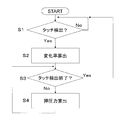
- FIG. 2 is a flowchart for explaining change rate calculation and pressing force calculation control.
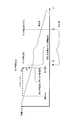
- FIG. 3 is a graph showing the piezoelectric output before and after correction.
- FIG. 3 shows the piezoelectric output before and after correction by the pressing force calculation unit 51.
- the electric charge due to pyroelectricity drift noise
- the piezoelectric output that is originally 0 changes linearly downward diagonally. is doing.
- step S ⁇ b> 1 of FIG. 2 the control unit 31 determines whether touch detection has been performed based on a signal from the touch detection unit 7. If touch detection is performed (Yes in step S1, touch detection (B) in FIG. 3), the process proceeds to step S2.
- the change rate calculating section 49 of the control unit 31 reads the data of the piezoelectric output of the previous time range from time t 1 of the touch detection time (B) from the storage unit 47, a touch detection based on it (B) to from the time t 1 calculated before the change rate of the piezoelectric output.
- the start time of the above time range is, for example, a time before a predetermined time from the time of touch detection (B). This time is set as the start time 0, and the time of touch detection (B) is expressed as time t 1 counted from the start time.
- step S ⁇ b> 3 the control unit 31 determines whether touch detection has been completed based on a signal from the touch detection unit 7. If touch detection ends (Yes in step S3, touch detection end (C)), the process returns to step S1, and if touch detection does not end (No in step S3), the process proceeds to step S4.
- step S4 the pressing force calculation unit 51 corrects the piezoelectric output acquired after the end time of the time range used for calculating the rate of change using the rate of change from the rate of change calculation unit 49. Calculate the pressing force. Specifically, the pressing force calculation unit 51 calculates the drift noise amount by multiplying the acquisition time of the piezoelectric output by the change rate described above (drift noise amount calculating step). Next, the pressing force calculation unit 51 corrects the piezoelectric output by subtracting the drift noise amount from the acquired piezoelectric output (drift noise amount subtraction step). Such a calculation is performed using the following equation.
- step S4 is repeatedly executed until the touch ends.
- the pressing force is calculated using the corrected piezoelectric output.
- the pressing force calculation unit 51 calculates the drift noise amount by multiplying the time at which the piezoelectric output is acquired by the rate of change, and the drift noise amount is obtained from the acquired piezoelectric output.
- the piezoelectric output is corrected by subtracting.
- the end time of the time range used to calculate the rate of change and from the time t 1 of the touch detection (B) a predetermined time before time.
- the timing at which the touch detection unit 7 detects contact with the pressure sensor 3 may be delayed from the time when the finger actually touches the pressure sensor 3, for example.
- the touch detection (B) the time t 1 there is a case where change in the piezoelectric output based on a press occurs by the detection delay time. In this case, the thus close the end time of the time range to the touch detection (B) the time t 1, the change of the piezoelectric output of the time range used on the change rate calculation is not a perfectly straight line.
- the end time of the time range used for the change rate calculated by the time t 1 of the touch detection (B) a predetermined time before the time change of the piezoelectric output in the time range of variation rate calculation approaches a straight line.
- the rate of change can be calculated more accurately.
- the time range for calculating the rate of change of the piezoelectric output with respect to time is an arbitrary time range before time t 1 of touch detection (B) in which the touch detection unit 7 detects contact with the pressure sensor 3. Correction of drift noise is possible.
- the change rate calculation step (step S2) is executed immediately after the touch detection step (step S1).
- the timing of the change rate calculation step is not limited to the above embodiment.
- the change rate calculating step may be performed at an appropriate time after the end of the previous touch detection.
- the change rate calculation unit 49 indicates the start time of the time range used to calculate the change rate, and the touch detection (B) in which the touch detection unit 7 detects contact with the pressure sensor 3.
- the time is a certain time before the time.
- the time corresponding to the touch start (A) is set as the start time 0 of the time range used for calculating the change rate.
- the start time of the time range used to calculate the change rate is not particularly limited, and may be, for example, before or after the touch start (A) time in FIG.
- the touch panel of the pressure sensor is disposed so as to overlap the piezoelectric sheet, but the present invention is not limited to this.
- the base material forming the touch detection electrode of the touch panel may also serve as the piezoelectric sheet.
- the contact to the pressure sensor of the contact target object was detected with the electrostatic capacitance system.
- the method for detecting contact of the contact object with the pressure sensor is not limited to the capacitance method.
- the contact of the contact object with the pressure sensor may be detected by a method other than the capacitance method (for example, a resistance film method, an optical method, an ultrasonic method, etc.).
- the present invention can be widely applied to a pressure detection device using a piezoelectric sheet that generates a piezoelectric signal corresponding to a given load.
- Pressure detector 3 Pressure sensor 5: Integration circuit 7: Touch detection unit 9: Microcomputer 21: Piezoelectric sheet 23: Touch panel 25: Operational amplifier 27: Capacitance 31: Control unit 39: AD converter 45: Acquisition unit 47: Storage unit 49: Change rate calculation unit 51: Pressure calculation unit
Landscapes
- Engineering & Computer Science (AREA)
- Physics & Mathematics (AREA)
- General Physics & Mathematics (AREA)
- Theoretical Computer Science (AREA)
- General Engineering & Computer Science (AREA)
- Human Computer Interaction (AREA)
- Force Measurement Appropriate To Specific Purposes (AREA)
- Position Input By Displaying (AREA)
- Electronic Switches (AREA)
Abstract
Description
本発明は、与えられた荷重に応じた圧電信号を発生する圧電シートを用いた、圧力検出装置、圧力検出装置の制御方法、及びプログラムに関する。
例えばタッチパネルへの押圧量を検出するため、圧電シートを用いた圧力センサが知られている。例えば、特許文献1には、透明感圧層と、一対の透明導電膜層とからなる透明圧電センサが開示されている。
特許文献1に開示されたような圧電シートを用いた圧力センサにおいては、温度変化が生じたときに、焦電性若しくは熱応力などが原因で圧電シートに電荷が発生してしまい、直線的に増加又は減少する圧電信号が出力することがある。この出力を「ドリフトノイズ」という。この結果、本来の圧電信号にドリフトノイズが重畳されてしまい、正確な押圧測定が困難になる。
「焦電性」とは、温度変化が起こったときにPVDFなどの圧電シートが電荷を発生する性質である。本明細書において、「熱応力」とは、圧力検出器やタッチパネルに温度変化が生じることで発生する圧電シートの内部応力のことである。つまり、熱応力は、支持基板などに圧電シートが配置されている場合に圧電シートの熱膨張や熱収縮が支持基板やタッチパネルによって妨げられることによって発生する応力や、圧電シートが面内に温度分布があるときに生じる応力、さらには圧電シート内の不均一性によって生じる応力などである。
本発明の課題は、圧力センサにおいて押圧力を精度良く測定可能にすることにある。
以下に、課題を解決するための手段として複数の態様を説明する。これら態様は、必要に応じて任意に組み合せることができる。
本発明の一見地に係る圧力検出装置は、圧力センサと、タッチ検出部と、取得部と、変化率算出部と、押圧力算出部とを有している。
圧力センサは、与えられた荷重に応じた圧電信号を発生する圧電シートを有する。
タッチ検出部は、圧力センサへの接触を検出する。
取得部は、圧電信号に基づく圧電出力を取得する。
変化率算出部は、タッチ検出部が圧力センサへの接触を検出するタッチ検出時刻より前の任意の時間範囲に取得された圧電出力の時間に対する変化率を算出する。
押圧力算出部は、変化率を算出するのに用いる時間範囲の終了時刻より後に取得された圧電出力を変化率を用いて補正することで、押圧力を算出する。
この装置では、押圧力は、補正後の圧電出力から算出される。これにより、例えば焦電性の影響によって圧電出力が例えば直線的に増加又は減少する場合に、前述の変化率を用いて、タッチ検出時刻後に取得された圧電出力を補正できる。つまり、温度変化に起因する圧電シートの電荷発生の変化の影響を無くすことができ、その結果、押圧力は正確に測定される。
押圧力算出部は、圧電出力を取得した時刻に変化率を掛けることでドリフトノイズ量を算出し、取得された圧電出力からドリフトノイズ量を減じることで、圧電出力を補正してもよい。
この装置では、上記補正によって、正確な押圧力が得られる。
変化率算出部は、変化率を算出するのに用いる時間範囲の終了時刻を、タッチ検出時刻から所定時間前の時刻としてもよい。
一般に、タッチ検出部による圧力センサへの接触を検出するタイミングは、実際に例えば指が圧力センサに触れた時刻から遅れることがある。そうすると、タッチ検出時刻より前であっても、検出遅れ時間によっては押圧に基づく圧電出力の変化が生じる場合がある。この場合、前記時間範囲の終了時刻をタッチ検出時刻に近づけてしまうと、時間範囲の圧電出力の変化は完全な直線にはならない。つまり、取得される変化率の精度がわずかながら落ちるので、補正の精度が低下する。そこで、前記時間範囲の終了時刻を、タッチ検出時刻から所定時間前の時刻とすることで、前記時間範囲における圧電出力の変化は直線に近づく。この結果、変化率をより正確に算出できる。
本発明の他の見地に係る圧力検出装置の制御方法は、与えられた荷重に応じた圧電信号を発生する圧電シートを有する圧力センサと、圧力センサへの接触を検出するタッチ検出部と、圧電信号に基づく圧電出力を取得する取得部とを備えた圧力検出装置の制御方法である。この制御方法は、下記のステップを有している。
◎タッチ検出部が圧力センサへの接触を検出すれば、タッチ検出時刻より前の任意の時間範囲に取得された圧電出力の時間に対する変化率を算出する変化率算出ステップ
◎変化率を算出するのに用いる時間範囲の終了時刻より後に取得された圧電出力を変化率を用いて補正することで、押圧力を算出する押圧力算出ステップ
この方法では、押圧力は、補正後の圧電出力を用いて算出される。これにより、例えば焦電性の影響によって圧電出力が例えば直線的に増加又は減少する場合に、前述の変化率を用いて、タッチ検出時刻後に取得された圧電出力を補正できる。つまり、温度変化に起因する圧電シートの電荷発生の変化の影響を無くすことができ、その結果、押圧力は正確に測定される。
押圧力算出ステップは、圧電出力を取得する時刻に変化率を掛けることでドリフトノイズ量を算出するドリフトノイズ量算出ステップと、取得された圧電出力からドリフトノイズ量を減じることで補正を行うドリフトノイズ量減算ステップとを有していてもよい。
本発明のさらに他の見地に係るプログラムは、コンピュータの記憶部に保存され、上記の圧力検出装置の制御方法をコンピュータに実行させる。
本発明に係る圧力検出装置では、圧電シートへの押圧を適切に検出することで、圧電シートへの押圧力を精度良く測定できる。
(1)圧力検出装置の全体構造
まず、本発明の一実施形態に係る圧力検出装置1の全体構造について図1を用いて説明する。図1は、本発明の第1実施形態に係る圧力検出装置の概略図である。
圧力検出装置1は、押圧荷重を測定する機能と、圧力センサへの接触を検出する機能とを有している。
圧力検出装置1は、主に、圧力センサ3と、積分回路5と、タッチ検出部7と、マイコン9とを有する。
圧力センサ3は、圧電シート21と、タッチパネル23とを有する。圧電シート21は、与えられた荷重に応じた圧電信号を発生する。
積分回路5は、圧電シート21からの出力される電荷の総量を電圧信号に変換する、つまり圧電信号を積分して出力する。出力される電圧信号を以下「圧電出力」という。これにより、圧電シート21の押圧力の変化量に起因して発生する微小な圧電信号から、圧電シート21の押圧力を精度良く測定できる。積分回路5は、圧電シートに接続された入力部を有するオペアンプ25と、入力部に一端が接続されるキャパシタンス27とを有する。
タッチ検出部7は、圧力センサ3のタッチパネル23への接触を検出する。タッチパネル23は、圧電シート21と積層されており、具体的にはタッチ検出電極(図示せず)を有している。
マイコン9は、図示しないが、基板と、基板に搭載されたCPU、RAM、ROM、その他電子部品とを有する。マイコン9は、主に、制御部31と、AD変換部39と有している。
制御部31は、CPU及びメモリからなるコンピュータのハードウェアとソフトウェアに基づいて、他の装置を制御するための装置である。
AD変換部39は、積分回路から出力されるアナログ電圧信号をデジタル電圧信号に変換する。
上記の各構成の機能は、後にさらに詳細に説明する。
(2)圧電シート
圧電シート21は、シート状の部材であり、両面に基準電極(図示せず)及び圧電検出電極(図示せず)が形成されている。その結果、検出電極(図示せず)と基準電極(図示せず)との間には、圧電シート21に与えられた荷重に応じた圧電信号が発生する。
圧電シート21を構成する材料としては、セラミック圧電材料、フッ化物重合体又はその共重合体、キラリティーを有する高分子材料などが挙げられる。セラミック圧電材料としては、チタン酸バリウム、チタン酸鉛、チタン酸ジルコン酸鉛、ニオブ酸カリウム、ニオブ酸リチウム、タンタル酸リチウムなどが挙げられる。フッ化物重合体又はその共重合体としては、ポリフッ化ビニリデン、フッ化ビニリデン-テトラフルオロエチレン共重合体、フッ化ビニリデン-トリフルオロエチレン共重合体などが挙げられる。キラリティーを有する高分子材料としては、L型ポリ乳酸や、R型ポリ乳酸などが挙げられる。
圧電シート21は、モノモルフでもよいし、バイモルフでもよい。
(3)電極
圧電検出電極(図示せず)、基準電極(図示せず)、及びタッチ検出電極(図示せず)は、導電性を有する材料により構成できる。導電性を有する材料としては、インジウム-スズ酸化物(Indium-Tin-Oxide、ITO)、スズ-亜鉛酸化物(Tin-Zinc-Oxide、TZO)などのような透明導電酸化物、ポリエチレンジオキシチオフェン(Polyethylenedioxythiophene、PEDOT)などの導電性高分子、などを用いることができる。この場合、上記の電極は、蒸着やスクリーン印刷などを用いて形成できる。
また、導電性を有する材料として、銅、銀などの導電性の金属を用いてもよい。この場合、上記の電極は、蒸着により形成してもよく、銅ペースト、銀ペーストなどの金属ペーストを用いて形成してもよい。
さらに、導電性を有する材料として、バインダー中に、カーボンナノチューブ、金属粒子、金属ナノファイバーなどの導電材料が分散したものを用いてもよい。
(4)タッチ検出部
タッチ検出部7は、圧力センサ3への接触を検出する装置である。この実施形態では、タッチパネル23のタッチ検出電極(図示せず)は、圧電シート21の圧電検出電極(示せず)とは電気的に絶縁されるように形成されている。これにより、タッチ検出部7は、ユーザの指などの接触対象物が圧力センサ3の主面に接触した際に発生するタッチ検出信号を、タッチ検出電極(図示せず)を介して、検出できる。なお、タッチパネル23は、ガラスカバー又は樹脂製カバーを含んでいる。
この圧力センサ3では、接触対象物が圧力センサ3の主面に接触したときにタッチ検出電極(図示せず)の自己容量又は相互容量が変化し、その変化が、タッチ検出部7にて検出される(静電容量方式)。静電容量方式を用いることで、タッチ検出部7は、ユーザの指が圧力センサ3を押圧する力が弱い場合でも、確実に指と圧力センサ3との接触を検出できる。
なお、タッチ検出部7としては、静電容量方式のタッチパネルなどに用いられている、公知の静電容量測定装置を用いることができる。
(5)積分回路
積分回路5は、2つの入力を有している。1つの入力は圧電シート21の圧電検出電極(図示せず)と接続され、もう1つの入力は基準電極(図示せず)に接続されている。
オペアンプ25は、2つの入力を有している。オペアンプ25の「-」を付した反転入力端子からの入力は、圧電シート21に形成された圧電検出電極(図示せず)へ接続されている。一方、オペアンプ25の「+」を付した非反転入力端子からの入力は、圧電シート21に形成された基準電極(図示せず)及びグランド電位に接続されている。この場合、圧電検出電極(図示せず)と基準電極(図示せず)との間に正の電位差を有した圧電信号が入力されると、オペアンプ25から負の電位差を有する増幅された圧電信号が出力される(反転増幅)。
オペアンプ25は、オペアンプ25の2つの入力への信号がわずかな電荷によるものである場合でも、信号の有無を判別可能な程度の信号を出力できる。そのため、オペアンプ25に圧電信号を入力することにより、微小な圧電信号から、精度良く圧電シート21に作用する押圧力を測定できるようになる。
キャパシタンス27は、その一端が、「-」を付したオペアンプ25の入力に接続されている。また、キャパシタンス27の他端が、オペアンプ25の出力に接続されている。
このようにして、圧電シート21の押圧力の変化量に起因して発生する電圧信号を積分して、オペアンプ25から増幅された圧電信号を出力できる。
なお、オペアンプ25としては、公知のオペアンプを用いることができる。また、キャパシタンス27としては、フィルムコンデンサ、セラミックコンデンサなどのコンデンサを用いることができる。キャパシタンス27として用いるコンデンサの容量は、圧電信号の強度などに応じて、適宜決定できる。
(6)マイコン
マイコン9は、CPU(Central Processing Unit)、記憶部、及び圧電センサを駆動するためのインターフェースなどを備えている。なお、マイコンの代わりに、カスタムICなどにより1つのICにマイコンの機能が集約されていてもよい。
制御部31は、タッチ検出部7の検出結果に応じて、他の装置の動作を制御する。そのために、制御部31は、タッチ検出部7とAD変換部39に接続されている。制御部31は、タッチ検出部7がタッチ検出信号の検出に基づいて出力する信号(タッチ信号)が入力されることで、タッチ検出部7がタッチ検出信号を検出したことを把握できる。
制御部31は、取得部45と、記憶部47と、変化率算出部49と、押圧力算出部51とを有している。
取得部45は、圧電信号に基づく圧電出力を取得する。具体的には、圧電出力は、常時取得され、その後、記憶部47に送信され、また、押圧力算出部51にも送信される。
記憶部47は、取得された圧電出力を時間単位で保存する。
変化率算出部49は、タッチ検出部7が圧力センサ3への接触を検出すれば、タッチ検出時刻より前に取得された圧電出力の時間に対する変化率を算出する。具体的には、変化率算出部49は、記憶部47から特定の時間範囲内の圧電出力を読み出して、前述の変化率を算出する。
押圧力算出部51は、取得された圧電出力を前述の変化率を用いて補正することで、押圧力を算出する。具体的には、押圧力算出部51は、取得部45から送信されてきた圧電出力を取得した時刻に前述の変化率を掛けることでドリフトノイズ量を算出し、さらに、取得された圧電出力からドリフトノイズ量を減じることで、圧電出力の補正を行う。これにより、例えば焦電性による電荷の影響が押圧力データから取り除かれる。
(7)制御動作
図2及び図3を用いて、制御部31による押圧力算出制御を説明する。図2は、変化率算出及び押圧力算出制御を説明するためのフローチャートである。図3は、補正前後の圧電出力を示すためのグラフである。
図3は、押圧力算出部51による補正前後の圧電出力を示している。図から明らかなように、補正前の圧電出力には焦電性による電荷(ドリフトノイズ)が押圧力よる電荷に重畳されており、したがって本来は0である圧電出力が斜め下方に直線状に変化している。
図2のステップS1では、制御部31は、タッチ検出部7からの信号に基づいてタッチ検出がされたか否かを判断する。タッチ検出がされれば(ステップS1でYes、図3のタッチ検出(B))、プロセスはステップS2に移行する。
ステップS2では、制御部31の変化率算出部49は、タッチ検出時刻(B)の時刻t1より前の時間範囲の圧電出力のデータを記憶部47から読み込み、それに基づいてタッチ検出(B)の時刻t1より前の圧電出力の変化率を算出する。この実施形態では、上記の時間範囲の開始時刻は、例えば、タッチ検出(B)の時刻から所定時間前の時刻である。この時刻を開始時刻0とし、タッチ検出(B)の時刻は開始時刻からカウントした時刻t1と表現される。
ステップS3では、制御部31は、タッチ検出部7からの信号に基づいてタッチ検出が終了したか否かを判断する。タッチ検出が終了すれば(ステップS3でYes、タッチ検出終了(C))プロセスはステップS1に戻り、タッチ検出が終了していなければ(ステップS3でNo)プロセスはステップS4に移行する。
ステップS4では、押圧力算出部51が、変化率を算出するのに用いる時間範囲の終了時刻より後に取得された圧電出力を、変化率算出部49からの変化率を用いて補正することで、押圧力を算出する。具体的には、押圧力算出部51は、圧電出力の取得時刻に前述の変化率を掛けることでドリフトノイズ量を算出する(ドリフトノイズ量算出ステップ)。次に、押圧力算出部51は、取得された圧電出力からドリフトノイズ量を減じることで、圧電出力を補正する(ドリフトノイズ量減算ステップ)。そのような計算は、下記の式を用いて行われる。
F(t)∝P(t)-(dD/dt)t-P(0)
なお、F(t)は時刻tでの押圧力であり、P(t)は時刻tでの圧電出力であり、tはタッチ開始時刻を0とした場合の時刻である。
ステップS4の後、プロセスはステップS3に戻る。つまり、タッチ終了まではステップS4が繰り返し実行される。
このようにして、タッチ認識中は、算出したドリフトノイズの傾き(dD/dt)を用いて、圧電出力を補正することで、押圧力を正確に算出できる。この結果、図3に示すように補正後の圧電出力が得られる。
上述のように、圧力検出装置1では、押圧力は、補正後の圧電出力を用いて算出される。これにより、温度変化に起因する圧電シートの電荷発生の変化の影響を無くすことができ、その結果、押圧力は正確に測定される。
具体的な実施形態としては、圧力検出装置1では、押圧力算出部51は、圧電出力を取得する時刻に変化率を掛けることでドリフトノイズ量を算出し、取得された圧電出力からドリフトノイズ量を減じることで、圧電出力を補正している。上記補正によって、正確な押圧力が得られる。ただし、押圧力は、変化率を算出するのに用いる時間範囲の終了時刻より後において補正後の圧電出力を用いて算出されればよいので、補正方法は本実施形態に限定されない。
なお、この実施形態では、変化率を算出するのに用いる時間範囲の終了時刻を、タッチ検出(B)の時刻t1から所定時間前の時刻としている。一般に、タッチ検出部7による圧力センサ3への接触を検出するタイミングは、実際に例えば指が圧力センサ3に触れた時刻から遅れることがある。そうすると、タッチ検出(B)時刻t1より前であっても、検出遅れ時間によっては押圧に基づく圧電出力の変化が生じる場合がある。この場合、前記時間範囲の終了時刻をタッチ検出(B)時刻t1に近づけてしまうと、変化率算出に用いる時間範囲の圧電出力の変化は完全な直線にはならない。つまり、取得される変化率の精度がわずかながら落ちるので、補正の精度が低下する。そこで、変化率算出に用いる時間範囲の終了時刻を、タッチ検出(B)の時刻t1から所定時間前の時刻とすることで、変化率算出の時間範囲における圧電出力の変化は直線に近づく。この結果、変化率をより正確に算出できる。
ただし、圧電出力の時間に対する変化率を算出する時間範囲は、タッチ検出部7が圧力センサ3への接触を検出するタッチ検出(B)の時刻t1より前の任意の時間範囲であれば、ドリフトノイズの補正は可能である。
(8)他の実施形態
以上、本発明の一実施形態について説明したが、本発明は上記実施形態に限定されるものではなく、発明の要旨を逸脱しない範囲で種々の変更が可能である。特に、本明細書に書かれた複数の実施形態及び変形例は必要に応じて任意に組み合せ可能である。
(a)前記実施形態では、図2に示すように、変化率算出ステップ(ステップS2)は、タッチ検出ステップ(ステップS1)の直後に実行された。これにより、タッチ検出直前のドリフトノイズの傾きを得ることができるので、タッチ検出より後の圧電出力を正確に補正できる。しかし、変化率を取得するためのドリフトノイズの傾きは、タッチ検出のドリフトノイズの傾きと同じ又は関連があればよいので、変化率算出ステップのタイミングは前記実施形態に限定されない。例えば、変化率算出ステップは、前回のタッチ検出終了後の適当な時刻に行われてもよい。
(b)前記実施形態では、変化率算出部49は、変化率を算出するのに用いる時間範囲の開始時刻を、タッチ検出部7が圧力センサ3への接触を検出したタッチ検出(B)の時刻からある時間前の時刻としている。具体的には、タッチ開始(A)に対応する時刻を、変化率を算出するのに用いる時間範囲の開始時刻0としている。
しかし、変化率を算出するのに用いる時間範囲の開始時刻は、特に限定されず、例えば、図3におけるタッチ開始(A)の時刻の前後であってもよい。
(c)前記実施形態では、ドリフトノイズの傾きが一定の場合を説明した。しかし、ドリフトノイズの傾きが多少変動する場合でも、本発明は有効に適用可能である。
(d)変化率を算出に用いる時間範囲は、タッチ毎に変更してもよい。
(e)本実施形態は、押圧力を正確に検出する他の手法と組み合わせてもよい。
(f)前記実施形態における圧力検出装置では、圧力センサのタッチパネルを圧電シートに重ねて配置したが、本発明はこれに限定されない。例えば、タッチパネルのタッチ検出電極を形成する基材が圧電シートを兼ねていてもよい。また、前記実施形態では、静電容量方式により、接触対象物の圧力センサへの接触を検出していた。しかし、接触対象物の圧力センサへの接触の検出方法は、静電容量方式に限られない。静電容量方式以外の方法(例えば、抵抗膜方式、光学方式、超音波方式など)により、接触対象物の圧力センサへの接触を検出してもよい。
本発明は、与えられた荷重に応じた圧電信号を発生する圧電シートを用いた、圧力検出装置に広く適用できる。
1 :圧力検出装置
3 :圧力センサ
5 :積分回路
7 :タッチ検出部
9 :マイコン
21 :圧電シート
23 :タッチパネル
25 :オペアンプ
27 :キャパシタンス
31 :制御部
39 :AD変換部
45 :取得部
47 :記憶部
49 :変化率算出部
51 :押圧力算出部
Claims (6)
-
与えられた荷重に応じた圧電信号を発生する圧電シートを有する圧力センサと、
前記圧力センサへの接触を検出するタッチ検出部と、
前記圧電信号に基づく圧電出力を取得する取得部と、
前記タッチ検出部が前記圧力センサへの接触を検出するタッチ検出時刻より前の任意の時間範囲に取得された圧電出力の時間に対する変化率を算出する変化率算出部と、
前記変化率を算出するのに用いる時間範囲の終了時刻より後に取得された圧電出力を前記変化率を用いて補正することで、押圧力を算出する押圧力算出部と、
を備える、圧力検出装置。
-
前記押圧力算出部は、前記圧電出力を取得した時刻に前記変化率を掛けることでドリフトノイズ量を算出し、取得された圧電出力から前記ドリフトノイズ量を減じることで前記補正を行う、請求項1に記載の圧力検出装置。
-
前記変化率算出部は、前記変化率を算出するのに用いる時間範囲の終了時刻を、前記タッチ検出時刻から所定時間前の時刻とする、請求項1又は2に記載の圧力検出装置。
-
与えられた荷重に応じた圧電信号を発生する圧電シートを有する圧力センサと、前記圧力センサへの接触を検出するタッチ検出部と、前記圧電信号に基づく圧電出力を取得する取得部とを備えた圧力検出装置の制御方法であって、
前記タッチ検出部が前記圧力センサへの接触を検出すれば、タッチ検出時刻より前の任意の時間範囲に取得された圧電出力の時間に対する変化率を算出する変化率算出ステップと、
前記変化率を算出するのに用いる時間範囲の終了時刻より後に取得された圧電出力を前記変化率を用いて補正することで、押圧力を算出する押圧力算出ステップと、
を備える、圧力検出装置の制御方法。
-
前記押圧力算出ステップは、前記圧電出力を取得する時刻に前記変化率を掛けることでドリフトノイズ量を算出するドリフトノイズ量算出ステップと、取得された圧電出力から前記ドリフトノイズ量を減じることで前記補正を行うドリフトノイズ量減算ステップとを有する、請求項4に記載の圧力検出装置の制御方法。
-
コンピュータの記憶部に保存され、請求項4又は5に記載の圧力検出装置の制御方法を前記コンピュータに実行させるプログラム。
Priority Applications (3)
| Application Number | Priority Date | Filing Date | Title |
|---|---|---|---|
| KR1020167023607A KR101734796B1 (ko) | 2014-10-17 | 2015-09-17 | 압력 검출 장치, 압력 검출 장치의 제어 방법, 및 프로그램 |
| CN201580013202.2A CN106104239B (zh) | 2014-10-17 | 2015-09-17 | 压力检测装置、压力检测装置的控制方法 |
| US15/306,271 US9885620B2 (en) | 2014-10-17 | 2015-09-17 | Pressure detecting apparatus, method of controlling the pressure detecting apparatus, and program |
Applications Claiming Priority (2)
| Application Number | Priority Date | Filing Date | Title |
|---|---|---|---|
| JP2014-213241 | 2014-10-17 | ||
| JP2014213241A JP5923585B2 (ja) | 2014-10-17 | 2014-10-17 | 圧力検出装置、圧力検出装置の制御方法、及びプログラム |
Publications (1)
| Publication Number | Publication Date |
|---|---|
| WO2016059935A1 true WO2016059935A1 (ja) | 2016-04-21 |
Family
ID=55746483
Family Applications (1)
| Application Number | Title | Priority Date | Filing Date |
|---|---|---|---|
| PCT/JP2015/076444 Ceased WO2016059935A1 (ja) | 2014-10-17 | 2015-09-17 | 圧力検出装置、圧力検出装置の制御方法、及びプログラム |
Country Status (5)
| Country | Link |
|---|---|
| US (1) | US9885620B2 (ja) |
| JP (1) | JP5923585B2 (ja) |
| KR (1) | KR101734796B1 (ja) |
| CN (1) | CN106104239B (ja) |
| WO (1) | WO2016059935A1 (ja) |
Families Citing this family (15)
| Publication number | Priority date | Publication date | Assignee | Title |
|---|---|---|---|---|
| CN105404420B (zh) * | 2015-11-04 | 2018-03-09 | 宸鸿科技(厦门)有限公司 | 压力感测信号处理方法及其系统 |
| CN106970728B (zh) * | 2017-05-09 | 2024-05-24 | 南京舜易暻机电科技有限公司 | 一种压电纤维交错排列的三维触摸感知结构及感知方法 |
| EP3647752B1 (en) * | 2017-06-26 | 2024-11-13 | Daikin Industries, Ltd. | Circuit and method for detecting pressure signal with signal due to pyroelectricity in piezoelectric material being suppressed |
| GB2570446B (en) * | 2018-01-23 | 2020-11-04 | Cambridge Touch Tech Ltd | Pressure signal processing |
| KR102139808B1 (ko) * | 2018-03-28 | 2020-07-31 | 주식회사 하이딥 | 복수 채널을 구성하는 압력 센서, 이를 포함하는 터치 입력 장치 및 이를 이용한 압력 검출 방법 |
| KR102261165B1 (ko) * | 2018-04-25 | 2021-06-07 | 주식회사 엘지에너지솔루션 | 이차 전지 정압 지그 및 이를 이용한 이차 전지 내부 압력 조절 방법 |
| US11009988B2 (en) * | 2018-05-04 | 2021-05-18 | Synaptics Incorporated | Using electrical resistance to estimate force on an electrode during temperature changes |
| CN112585441A (zh) * | 2018-11-19 | 2021-03-30 | 株式会社三国 | 压力检测信号处理装置、发动机控制系统及程序 |
| GB2585653B (en) * | 2019-07-09 | 2022-03-23 | Cambridge Touch Tech Ltd | Force signal processing |
| JP7211563B2 (ja) | 2020-07-10 | 2023-01-24 | 株式会社村田製作所 | 押圧力検知装置 |
| JP2022083296A (ja) * | 2020-11-24 | 2022-06-03 | シャープ株式会社 | タッチパネルシステム、表示装置及びタッチパネルシステムの制御方法 |
| DE112021007040B4 (de) * | 2021-04-13 | 2025-02-06 | Mitsubishi Electric Corporation | Kontaktinformationen-bezugsvorrichtung, kontaktinformationen-bezugssystem, kontaktinformationen-bezugsverfahren und kontaktinformationen-bezugsprogramm |
| JP2022166512A (ja) | 2021-04-21 | 2022-11-02 | シャープディスプレイテクノロジー株式会社 | タッチパネルシステム及び表示装置 |
| US12327640B2 (en) * | 2022-04-01 | 2025-06-10 | Jiangxi Provincial People's Hospital | Finger kneading rating method based on intelligent model processing |
| JP2024115842A (ja) | 2023-02-15 | 2024-08-27 | シャープディスプレイテクノロジー株式会社 | タッチパネルシステム及び表示装置 |
Citations (3)
| Publication number | Priority date | Publication date | Assignee | Title |
|---|---|---|---|---|
| JPS5651641A (en) * | 1979-10-04 | 1981-05-09 | Toyo Tire & Rubber Co Ltd | Tester for tire tumbling resistance |
| JP2013246557A (ja) * | 2012-05-24 | 2013-12-09 | Asahi Kasei Electronics Co Ltd | タッチセンサの信号処理回路、およびタッチセンサ |
| JP2014134452A (ja) * | 2013-01-10 | 2014-07-24 | Nissha Printing Co Ltd | 接着層付きフィルム状感圧センサとこれを用いたタッチパッド、タッチ入力機能付き保護パネル及び電子機器 |
Family Cites Families (15)
| Publication number | Priority date | Publication date | Assignee | Title |
|---|---|---|---|---|
| AT388830B (de) * | 1988-01-25 | 1989-09-11 | Avl Verbrennungskraft Messtech | Ladungsverstaerkerschaltung |
| US7532202B2 (en) * | 2002-05-08 | 2009-05-12 | 3M Innovative Properties Company | Baselining techniques in force-based touch panel systems |
| JP2004125571A (ja) * | 2002-10-01 | 2004-04-22 | National Institute Of Advanced Industrial & Technology | 透明圧電センサおよびそれを備えた入力装置 |
| JP4309158B2 (ja) * | 2003-03-19 | 2009-08-05 | 富士重工業株式会社 | 電荷信号変換アンプ、及び筒内圧測定装置 |
| JP3863505B2 (ja) * | 2003-06-20 | 2006-12-27 | 忠弘 大見 | 圧力センサ及び圧力制御装置並びに圧力式流量制御装置の自動零点補正装置 |
| US7117725B2 (en) * | 2004-03-12 | 2006-10-10 | Honda Motor Co., Ltd. | In-cylinder pressure detecting apparatus |
| JP4271652B2 (ja) * | 2004-12-27 | 2009-06-03 | 本田技研工業株式会社 | 筒内圧検出装置 |
| US7334483B2 (en) * | 2006-01-27 | 2008-02-26 | Schlumberger Technology Corporation | Thermal compensation of pressure measurements |
| CN101275878A (zh) * | 2007-03-27 | 2008-10-01 | 捷顶微电子(上海)有限公司 | 一种压力传感器的温度漂移的补偿方法 |
| FR2938645B1 (fr) * | 2008-11-19 | 2012-03-02 | Continental Automotive France | Procede de correction de la derive du signal d'un capteur de pression |
| WO2010140814A2 (ko) | 2009-06-03 | 2010-12-09 | 주식회사 쎄믹스 | 척의 능동적 기울기 제어가 가능한 웨이퍼 프로브 스테이션 및 그 제어방법 |
| JP5507323B2 (ja) * | 2010-04-23 | 2014-05-28 | 本田技研工業株式会社 | 力覚センサの温度補償方法および力覚センサ |
| TWI579797B (zh) * | 2012-08-31 | 2017-04-21 | 禾瑞亞科技股份有限公司 | 影像分割的處理器 |
| JP5897055B2 (ja) * | 2014-03-07 | 2016-03-30 | 日本写真印刷株式会社 | 感圧センサ及びタッチパネル |
| US20170131840A1 (en) * | 2014-06-17 | 2017-05-11 | Corning Incorporated | Algorithms and implementation of touch pressure sensors |
-
2014
- 2014-10-17 JP JP2014213241A patent/JP5923585B2/ja not_active Expired - Fee Related
-
2015
- 2015-09-17 WO PCT/JP2015/076444 patent/WO2016059935A1/ja not_active Ceased
- 2015-09-17 KR KR1020167023607A patent/KR101734796B1/ko active Active
- 2015-09-17 CN CN201580013202.2A patent/CN106104239B/zh active Active
- 2015-09-17 US US15/306,271 patent/US9885620B2/en not_active Expired - Fee Related
Patent Citations (3)
| Publication number | Priority date | Publication date | Assignee | Title |
|---|---|---|---|---|
| JPS5651641A (en) * | 1979-10-04 | 1981-05-09 | Toyo Tire & Rubber Co Ltd | Tester for tire tumbling resistance |
| JP2013246557A (ja) * | 2012-05-24 | 2013-12-09 | Asahi Kasei Electronics Co Ltd | タッチセンサの信号処理回路、およびタッチセンサ |
| JP2014134452A (ja) * | 2013-01-10 | 2014-07-24 | Nissha Printing Co Ltd | 接着層付きフィルム状感圧センサとこれを用いたタッチパッド、タッチ入力機能付き保護パネル及び電子機器 |
Also Published As
| Publication number | Publication date |
|---|---|
| JP2016080551A (ja) | 2016-05-16 |
| US9885620B2 (en) | 2018-02-06 |
| JP5923585B2 (ja) | 2016-05-24 |
| KR101734796B1 (ko) | 2017-05-11 |
| US20170052074A1 (en) | 2017-02-23 |
| CN106104239B (zh) | 2017-12-26 |
| CN106104239A (zh) | 2016-11-09 |
| KR20160105540A (ko) | 2016-09-06 |
Similar Documents
| Publication | Publication Date | Title |
|---|---|---|
| JP5923585B2 (ja) | 圧力検出装置、圧力検出装置の制御方法、及びプログラム | |
| JP5765442B2 (ja) | 変位センサ | |
| JP7309118B2 (ja) | 圧力信号処理 | |
| JP7252832B2 (ja) | 圧力感知装置及び方法 | |
| JP7309119B2 (ja) | 圧力検知装置及び方法 | |
| JP5954500B2 (ja) | タッチ式入力装置 | |
| JP5794399B2 (ja) | タッチ式入力装置 | |
| US10809857B2 (en) | Electronic device | |
| TWI400646B (zh) | 觸控感測元件之壓力偵測方法以及使用該方法之電子裝置 | |
| WO2016059940A1 (ja) | 圧力検出装置、圧力検出装置の制御方法、及びプログラム | |
| JP7556894B2 (ja) | 力信号処理 | |
| JP6139185B2 (ja) | 圧力検出装置 | |
| JP2014202618A (ja) | 圧力検出装置 | |
| JP6607972B2 (ja) | 静電容量値を測定するための方法 | |
| JP6285259B2 (ja) | 圧力センサ |
Legal Events
| Date | Code | Title | Description |
|---|---|---|---|
| 121 | Ep: the epo has been informed by wipo that ep was designated in this application |
Ref document number: 15849870 Country of ref document: EP Kind code of ref document: A1 |
|
| ENP | Entry into the national phase |
Ref document number: 20167023607 Country of ref document: KR Kind code of ref document: A |
|
| WWE | Wipo information: entry into national phase |
Ref document number: 15306271 Country of ref document: US |
|
| NENP | Non-entry into the national phase |
Ref country code: DE |
|
| 122 | Ep: pct application non-entry in european phase |
Ref document number: 15849870 Country of ref document: EP Kind code of ref document: A1 |