WO2016059874A1 - Fluid mixing device - Google Patents
Fluid mixing device Download PDFInfo
- Publication number
- WO2016059874A1 WO2016059874A1 PCT/JP2015/073482 JP2015073482W WO2016059874A1 WO 2016059874 A1 WO2016059874 A1 WO 2016059874A1 JP 2015073482 W JP2015073482 W JP 2015073482W WO 2016059874 A1 WO2016059874 A1 WO 2016059874A1
- Authority
- WO
- WIPO (PCT)
- Prior art keywords
- flow path
- flow
- fluid
- mixing device
- units
- Prior art date
Links
Images


Classifications
-
- B—PERFORMING OPERATIONS; TRANSPORTING
- B01—PHYSICAL OR CHEMICAL PROCESSES OR APPARATUS IN GENERAL
- B01F—MIXING, e.g. DISSOLVING, EMULSIFYING OR DISPERSING
- B01F33/00—Other mixers; Mixing plants; Combinations of mixers
- B01F33/30—Micromixers
- B01F33/301—Micromixers using specific means for arranging the streams to be mixed, e.g. channel geometries or dispositions
-
- B—PERFORMING OPERATIONS; TRANSPORTING
- B01—PHYSICAL OR CHEMICAL PROCESSES OR APPARATUS IN GENERAL
- B01F—MIXING, e.g. DISSOLVING, EMULSIFYING OR DISPERSING
- B01F25/00—Flow mixers; Mixers for falling materials, e.g. solid particles
- B01F25/40—Static mixers
- B01F25/42—Static mixers in which the mixing is affected by moving the components jointly in changing directions, e.g. in tubes provided with baffles or obstructions
- B01F25/43—Mixing tubes, e.g. wherein the material is moved in a radial or partly reversed direction
- B01F25/432—Mixing tubes, e.g. wherein the material is moved in a radial or partly reversed direction with means for dividing the material flow into separate sub-flows and for repositioning and recombining these sub-flows; Cross-mixing, e.g. conducting the outer layer of the material nearer to the axis of the tube or vice-versa
- B01F25/4321—Mixing tubes, e.g. wherein the material is moved in a radial or partly reversed direction with means for dividing the material flow into separate sub-flows and for repositioning and recombining these sub-flows; Cross-mixing, e.g. conducting the outer layer of the material nearer to the axis of the tube or vice-versa the subflows consisting of at least two flat layers which are recombined, e.g. using means having restriction or expansion zones
-
- B—PERFORMING OPERATIONS; TRANSPORTING
- B01—PHYSICAL OR CHEMICAL PROCESSES OR APPARATUS IN GENERAL
- B01F—MIXING, e.g. DISSOLVING, EMULSIFYING OR DISPERSING
- B01F25/00—Flow mixers; Mixers for falling materials, e.g. solid particles
- B01F25/40—Static mixers
- B01F25/42—Static mixers in which the mixing is affected by moving the components jointly in changing directions, e.g. in tubes provided with baffles or obstructions
- B01F25/421—Static mixers in which the mixing is affected by moving the components jointly in changing directions, e.g. in tubes provided with baffles or obstructions by moving the components in a convoluted or labyrinthine path
-
- B—PERFORMING OPERATIONS; TRANSPORTING
- B01—PHYSICAL OR CHEMICAL PROCESSES OR APPARATUS IN GENERAL
- B01F—MIXING, e.g. DISSOLVING, EMULSIFYING OR DISPERSING
- B01F33/00—Other mixers; Mixing plants; Combinations of mixers
- B01F33/30—Micromixers
-
- B—PERFORMING OPERATIONS; TRANSPORTING
- B01—PHYSICAL OR CHEMICAL PROCESSES OR APPARATUS IN GENERAL
- B01L—CHEMICAL OR PHYSICAL LABORATORY APPARATUS FOR GENERAL USE
- B01L3/00—Containers or dishes for laboratory use, e.g. laboratory glassware; Droppers
- B01L3/50—Containers for the purpose of retaining a material to be analysed, e.g. test tubes
- B01L3/502—Containers for the purpose of retaining a material to be analysed, e.g. test tubes with fluid transport, e.g. in multi-compartment structures
-
- B—PERFORMING OPERATIONS; TRANSPORTING
- B01—PHYSICAL OR CHEMICAL PROCESSES OR APPARATUS IN GENERAL
- B01F—MIXING, e.g. DISSOLVING, EMULSIFYING OR DISPERSING
- B01F2101/00—Mixing characterised by the nature of the mixed materials or by the application field
- B01F2101/2202—Mixing compositions or mixers in the medical or veterinary field
-
- B—PERFORMING OPERATIONS; TRANSPORTING
- B01—PHYSICAL OR CHEMICAL PROCESSES OR APPARATUS IN GENERAL
- B01F—MIXING, e.g. DISSOLVING, EMULSIFYING OR DISPERSING
- B01F2101/00—Mixing characterised by the nature of the mixed materials or by the application field
- B01F2101/23—Mixing of laboratory samples e.g. in preparation of analysing or testing properties of materials
-
- B—PERFORMING OPERATIONS; TRANSPORTING
- B01—PHYSICAL OR CHEMICAL PROCESSES OR APPARATUS IN GENERAL
- B01L—CHEMICAL OR PHYSICAL LABORATORY APPARATUS FOR GENERAL USE
- B01L2200/00—Solutions for specific problems relating to chemical or physical laboratory apparatus
- B01L2200/16—Reagents, handling or storing thereof
-
- B—PERFORMING OPERATIONS; TRANSPORTING
- B01—PHYSICAL OR CHEMICAL PROCESSES OR APPARATUS IN GENERAL
- B01L—CHEMICAL OR PHYSICAL LABORATORY APPARATUS FOR GENERAL USE
- B01L2300/00—Additional constructional details
- B01L2300/08—Geometry, shape and general structure
- B01L2300/0861—Configuration of multiple channels and/or chambers in a single devices
- B01L2300/0864—Configuration of multiple channels and/or chambers in a single devices comprising only one inlet and multiple receiving wells, e.g. for separation, splitting
-
- B—PERFORMING OPERATIONS; TRANSPORTING
- B01—PHYSICAL OR CHEMICAL PROCESSES OR APPARATUS IN GENERAL
- B01L—CHEMICAL OR PHYSICAL LABORATORY APPARATUS FOR GENERAL USE
- B01L2300/00—Additional constructional details
- B01L2300/08—Geometry, shape and general structure
- B01L2300/0861—Configuration of multiple channels and/or chambers in a single devices
- B01L2300/0867—Multiple inlets and one sample wells, e.g. mixing, dilution
-
- B—PERFORMING OPERATIONS; TRANSPORTING
- B01—PHYSICAL OR CHEMICAL PROCESSES OR APPARATUS IN GENERAL
- B01L—CHEMICAL OR PHYSICAL LABORATORY APPARATUS FOR GENERAL USE
- B01L2300/00—Additional constructional details
- B01L2300/08—Geometry, shape and general structure
- B01L2300/0887—Laminated structure
Landscapes
- Chemical & Material Sciences (AREA)
- Chemical Kinetics & Catalysis (AREA)
- Dispersion Chemistry (AREA)
- Health & Medical Sciences (AREA)
- Analytical Chemistry (AREA)
- General Health & Medical Sciences (AREA)
- Hematology (AREA)
- Clinical Laboratory Science (AREA)
- Physical Or Chemical Processes And Apparatus (AREA)
Abstract
[Problem] To provide a fluid mixing device with which the mixing rate for multiple fluids can be significantly increased without changing device setup area. [Solution] A fluid mixing device is provided with multiple flow channel units (20a-20g) that are divided and disposed in multiple layers. Each flow channel unit comprises an inflow port, an outflow port, and multiple branch flow channels in communication with the inflow port and the outflow port. Flow channel units located in different layers are connected to each other, inflow port to outflow port between flow channel units, to configure an overall three-dimensional flow channel (4). When the direction from the inflow port of each flow channel unit towards the outflow channel is called the flow direction for the flow channel unit, the flow directions of the various layers intersect.
Description
本発明は、流入した複数の流体を混合させて流出する流体混合装置に関する。
The present invention relates to a fluid mixing apparatus that mixes a plurality of inflowing fluids and flows out.
流体混合装置としては、人体摂取物などの試料と試薬を混合させて化学反応させたり、分析したりするマイクロミキサーやマイクロリアクタが挙げられる。特許文献1に開示されている流体混合装置は、流路プレートに溝を設けて流路を形成するものである。この流路は、試料と試薬をそれぞれ導入する2つの流入路と、1つの流出路を備え、2つの流入路に導入された試料と試薬を合流させて流出路に導くようになっている。
Examples of the fluid mixing device include a micromixer and a microreactor for mixing a sample such as human body intake with a reagent and causing a chemical reaction or analysis. The fluid mixing device disclosed in Patent Document 1 forms a channel by providing a groove in a channel plate. This flow path is provided with two inflow paths for introducing the sample and the reagent, respectively, and one outflow path, and the sample and the reagent introduced to the two inflow paths are combined and led to the outflow path.
特許文献1に記載された流体混合装置の流路は、平面的であり、試料と試薬は、2つの流入路から合流して流出路まで一方向に流れる。このような平面的な流路では、流体を合流させても、混合効率が悪いという問題がある。また、混合効率を高めるために、合流させる流路を長くしたり、分岐と合流の数を増やしたりすることも考えられるが、このような流路構成では設置面積が大きくなってしまう。
The flow path of the fluid mixing device described in Patent Document 1 is planar, and the sample and the reagent flow from one of the two inflow paths into one direction to the outflow path. In such a planar flow path, there is a problem that the mixing efficiency is poor even if the fluids are merged. In order to increase the mixing efficiency, it is also conceivable to lengthen the flow path to be merged or to increase the number of branching and merging, but in such a flow channel configuration, the installation area becomes large.
本発明は、上記従来の課題を解決するものであり、設置面積を過大にすることなく流体の混合率を効率良く高めることができる流体混合装置を提供することを目的としている。
The present invention solves the above-mentioned conventional problems, and an object of the present invention is to provide a fluid mixing device capable of efficiently increasing the fluid mixing ratio without making the installation area excessive.
本発明の流体混合装置は、複数の流体を混合する流体混合装置であって、
複数の階層に分かれて配置された複数の流路単位を備え、
前記流路単位はそれぞれ、流入口と、流出口と、前記流入口と前記流出口とを連通する複数の分岐流路と、を有し、
互いに異なる階層に位置する一方の前記流路単位の前記流入口と他方の前記流路単位の前記流出口とが連結されて立体流路が構成されており、
前記流入口から前記流出口へ向かう方向を、個々の前記流路単位における流体の流れ方向としたときに、その流れ方向が各階層間で交差していることを特徴とするものである。 The fluid mixing device of the present invention is a fluid mixing device for mixing a plurality of fluids, wherein
It has a plurality of flow path units divided and arranged in a plurality of layers,
Each of the flow path units includes an inlet, an outlet, and a plurality of branch channels communicating the inlet and the outlet.
The inflow port of one of the flow path units located in different layers and the outflow port of the other of the flow path units are connected to constitute a three-dimensional flow path,
When the direction from the inflow port to the outflow port is a flow direction of fluid in each of the flow path units, the flow directions cross each other between the layers.
本発明の流体混合装置は、複数の流体が流入されると、立体流路の各流路単位を通って、分流、合流、方向転換が繰り返されるので、流体を効率良く混合して流出させることができる。このとき、流路単位の流れ方向が各階層間で交差しているので、各階層の流路単位を流れるごとに、流体を異なる方向へ分割することができ、さらに分割された流体を合流させ、この分割と合流を方向を変えて繰り返えすことができる。これにより、複数の流体の混合効率を大幅に向上させることができる。さらに、各階層に流路単位を配置するので、階層を増やすことによって流路単位を増やすことができる。これにより、設置面積を変えることなく、複数の流体の混合効率を効率良く高めることができる。
According to the fluid mixing apparatus of the present invention, when a plurality of fluids are inflowed, the fluid flow is efficiently mixed and flowed out because the flow division, merging and turning are repeated through each flow path unit of the three-dimensional flow path. Can. At this time, since the flow direction of the flow path unit intersects between the layers, the fluid can be divided in different directions each time it flows in the flow path unit of each hierarchy, and the divided fluids are merged. It is possible to repeat this division and merging in different directions. Thereby, the mixing efficiency of a plurality of fluids can be greatly improved. Furthermore, since channel units are arranged in each layer, channel units can be increased by increasing the number of layers. Thereby, the mixing efficiency of a plurality of fluids can be efficiently enhanced without changing the installation area.
本発明の流体混合装置においては、連結されている前記流路単位の流れ方向が、互いに直交していることが好ましい。
In the fluid mixing apparatus of the present invention, it is preferable that the flow directions of the connected flow path units are orthogonal to each other.
異なる階層に配置された流路単位の流れ方向を直交させることで、一方の流路単位から次の流路単位に至ったときに流体を直交方向へ分岐させることができるようになり、流体の混合効率を高めることができる。
By making the flow directions of the flow path units arranged in different layers orthogonal, the fluid can be branched in the orthogonal direction when one flow path unit reaches the next flow path unit. Mixing efficiency can be increased.
本発明の流体混合装置は、前記流路単位の分岐流路は、前記流入口から流入した流体を2つに分割してそれら分流流体がそれぞれ離れる方向に導く2つの第1流路と、それぞれの前記第1流路からターンして互いに近づく方向に分流流体を導いて合流させる2つの第2流路とからなるものとして構成される。
In the fluid mixing apparatus according to the present invention, the branch flow paths of the flow path unit are two first flow paths each of which divides the fluid flowing in from the inflow port into two and directs the divided fluids in the respective directions; The second flow path is configured to be turned from the first flow path of the second flow path and to guide the divided fluids in a direction approaching each other and to join them.
この場合に、前記2つの第1流路のなす角は90度より大きく180度以下の角度であり、前記2つの第2流路のなす角は180度より小さい角度であることが好ましい。また、前記第1流路と前記第2流路は直線又は曲線であることが好ましい。
In this case, it is preferable that an angle formed by the two first flow paths be an angle larger than 90 degrees and equal to or smaller than 180 degrees, and an angle formed by the two second flow paths be an angle smaller than 180 degrees. Moreover, it is preferable that the said 1st flow path and the said 2nd flow path are a straight line or a curve.
本発明は、少なくとも1つの前記階層に、前記流路単位が複数配置されていることが好ましい。
In the present invention, preferably, a plurality of the flow path units are arranged in at least one of the layers.
また、前記複数の流路単位を有する少なくとも2つの前記階層が重ねられているものがさらに好ましい。
Furthermore, it is further preferable that at least two of the layers having the plurality of flow path units are overlapped.
本発明の流体混合装置は、複数の流路プレートがその厚み方向に重ねられて積層され、一方の流路プレートの表面に形成された溝と、これに重ねられる他方の流路プレートの平面との間に前記流路単位が形成されており、3枚以上の前記流路プレートが重ねられることにより、複数の前記階層が形成されているものとして構成できる。
In the fluid mixing apparatus of the present invention, a plurality of flow channel plates are stacked and stacked in the thickness direction, and a groove formed on the surface of one flow channel plate and a flat surface of the other flow channel plate stacked thereon The flow path unit is formed between the plurality of flow path plates, and three or more of the flow path plates may be stacked to form a plurality of the layers.
本発明の流体混合装置は、流路単位の流れ方向が各階層間で交差しているので、各階層の流路単位に流れるごとに、流体を分割することができ、しかもそのような流体の分割と集合を、方向を変えながら繰り返すことができる。よって、複数の流体の混合効率を大幅に向上させることができる。さらに、階層を増やすことで、流路単位を増やすことができので、平面積を広くすることなく、流体の混合効率を高めることができる。
In the fluid mixing apparatus according to the present invention, since the flow direction of the flow path unit intersects between the layers, the fluid can be divided each time it flows in the flow path unit of each layer, and such fluid Partitioning and aggregation can be repeated changing directions. Therefore, the mixing efficiency of a plurality of fluids can be greatly improved. Furthermore, by increasing the number of layers, it is possible to increase the number of flow path units, so it is possible to increase the mixing efficiency of the fluid without widening the plane area.
以下に添付図面を参照しながら,本発明の実施形態に係る流体混合装置について詳細に説明する。ここでは、血液などの人体摂取物試料と試薬を混合させる流体混合装置を例に挙げる。ただし、混合すべき流体はこれに限られるものではない。
Hereinafter, a fluid mixing apparatus according to an embodiment of the present invention will be described in detail with reference to the accompanying drawings. Here, a fluid mixing apparatus that mixes a human body ingestible sample such as blood with a reagent will be described as an example. However, the fluid to be mixed is not limited to this.
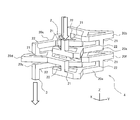
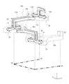
図1は、本発明の実施形態に係る流体混合装置1の全体構成を示す外観斜視図であり、図2は、流体混合装置1の内部に形成される立体流路の形状を示す図である。
FIG. 1 is an external perspective view showing the entire configuration of a fluid mixing device 1 according to an embodiment of the present invention, and FIG. 2 is a diagram showing the shape of a three-dimensional flow path formed inside the fluid mixing device 1. .
図1に示す流体混合装置1は、その最上部に設けられた流体入口2と、最下部に設けられた流体出口3を備える。流体入口2と流体出口3は、流体混合装置1の内部に形成される立体流路4に通じている。複数の流体が流体入口2から流入されると、立体流路4で混合されて流体出口3から流出される。
The fluid mixing device 1 shown in FIG. 1 includes a fluid inlet 2 provided at the top and a fluid outlet 3 provided at the bottom. The fluid inlet 2 and the fluid outlet 3 communicate with a three-dimensional flow channel 4 formed inside the fluid mixing device 1. When a plurality of fluids flow in from the fluid inlet 2, they are mixed in the three-dimensional channel 4 and flow out from the fluid outlet 3.
図2に示すように、立体流路4は、上下方向に並ぶ複数の階層に配置された複数の流路単位20によって構成される。これらの流路単位20は、同様の基本形状により構成され、複数の階層に分かれて配置されている。図2に示す立体流路4は、7つの流路単位20が4つの階層に分かれて配置されている。図2以下では、個々の流路単位20を区別するために、個々の流路単位に符号20a~20gを付して説明することがある。流体入口2から流体が導入されると、流路単位20a→20b→20c→20d→20e→20f→20gの順に流体が流れて、流体出口3から排出される。
As shown in FIG. 2, the three-dimensional flow path 4 is configured by a plurality of flow path units 20 arranged in a plurality of layers arranged in the vertical direction. These flow path units 20 are configured in the same basic shape, and are divided into a plurality of layers and arranged. In the three-dimensional flow path 4 shown in FIG. 2, seven flow path units 20 are arranged in four layers. In FIG. 2 and the following, in order to distinguish the individual flow path units 20, the individual flow path units may be described with reference numerals 20a to 20g. When the fluid is introduced from the fluid inlet 2, the fluid flows in the order of the channel units 20 a → 20 b → 20 c → 20 d → 20 e → 20 f → 20 g and is discharged from the fluid outlet 3.
図2に示す立体流路4の階層を上から第1~第4階層とすると、第1階層に1つの流路単位20bが配置され、第2階層に2つの流路単位20a、20cが配置されている。第3階層に2つの流路単位20f、20dが配置され、第4階層に2つの流路単位20e、20gが配置されている。
Assuming that the hierarchy of the three-dimensional flow channel 4 shown in FIG. 2 is the first to fourth hierarchy from the top, one flow passage unit 20b is disposed in the first hierarchy, and two flow passage units 20a and 20c are disposed in the second hierarchy. It is done. Two flow path units 20f and 20d are disposed in the third level, and two flow path units 20e and 20g are disposed in the fourth level.
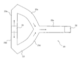
ここで、各流路単位20a~20gの基本形状について図面を参照しながら説明する。図3は本実施形態における流路単位20の基本形状を示す斜視図であり、図4は図3に示す流路単位の基本形状の平面図である。
Here, the basic shape of each flow path unit 20a to 20g will be described with reference to the drawings. FIG. 3 is a perspective view showing the basic shape of the flow path unit 20 in the present embodiment, and FIG. 4 is a plan view of the basic shape of the flow path unit shown in FIG.
図3と図4に示すように、流路単位20はそれぞれ、流入口21と、流出口22を備え、流入口21から流入する流体が流出口22に向けて一方向(ここでは水平方向)の流れを形成するように構成される。流入口21から流出口22までの途中には、これらを連通する2つの分岐流路23が形成されている。
As shown in FIGS. 3 and 4, each of the flow path units 20 includes an inlet 21 and an outlet 22, and the fluid flowing in from the inlet 21 is directed to the outlet 22 in one direction (here, in the horizontal direction). Configured to form a flow of On the way from the inflow port 21 to the outflow port 22, two branch flow paths 23 communicating these are formed.
分岐流路23は、流入口21から流入した流体を2つに分岐し、分流した流体を互いに離れる方向に導く2つの第1流路23a、23bと、各第1流路23a、23bからターンして互いに近づく方向に流体を導いて合流させる2つの第2流路23c、23dとから構成されている。第1流路23a、23bのなす角度αは90度より大きく180度以下であり、第2流路23c、23dのなす角度βは180度より小さい。これにより、分流した流れをターンさせて合流させることができる。図4に示す実施の形態では、第1流路23a、23bのなす角度αが180度で、第2流路23c、23dのなす角度βが90度である。流入口21から流入した流体を効率よく分割させるためには、第1流路23a、23bのなす角度αが180度であることが好ましい。
The branch channel 23 branches the fluid flowing in from the inlet 21 into two, and guides the branched fluid away from each other in two first channels 23a and 23b, and turns from each first channel 23a and 23b. And two second flow paths 23c and 23d for guiding and joining the fluids in a direction approaching each other. The angle α between the first flow paths 23a and 23b is greater than 90 degrees and is equal to or less than 180 degrees, and the angle β between the second flow paths 23c and 23d is smaller than 180 degrees. This allows the diverted flows to turn and merge. In the embodiment shown in FIG. 4, the angle α between the first flow paths 23a and 23b is 180 degrees, and the angle β between the second flow paths 23c and 23d is 90 degrees. In order to efficiently divide the fluid flowing in from the inflow port 21, it is preferable that an angle α between the first flow paths 23a and 23b be 180 degrees.
図3に示す流路単位20では、第2流路23c、23dを経て合流した流体をさらに流出口22に導く合流流路23eが連続して形成されている。
In the flow path unit 20 shown in FIG. 3, a merging flow path 23 e for continuously guiding the fluid merged through the second flow paths 23 c and 23 d to the outlet 22 is continuously formed.
図2に示す立体流路4では、異なる階層に位置する流路単位20どうしが連結されている。例えば、流路単位20aの流出口22は、その上の階層に位置する流路単位20bの流入口21に連結され、流路単位20bの流出口22は、その下の階層に位置する流路単位20cの流入口21と連結されている。
In the three-dimensional flow path 4 shown in FIG. 2, flow path units 20 located in different layers are connected to each other. For example, the outlet 22 of the channel unit 20a is connected to the inlet 21 of the channel unit 20b located in the upper layer, and the outlet 22 of the channel unit 20b is located in the lower layer. It is connected to the inlet 21 of the unit 20c.
そのため、個々の流路単位20では、流入口21と流出口22の開口方向すなわち、流入口21と流出口22で流体が流れる方向が、流路単位20の流体の流れの方向(図3の紙面)に対して垂直方向に向けられている。
Therefore, in each flow path unit 20, the opening direction of the inflow port 21 and the outflow port 22, that is, the flow direction of the fluid at the inflow port 21 and the outflow port 22 Perpendicular to the paper).
流入口21と流路口22は、どの階層の流路単位と接続するかによって、上側または下側のいずれかに向けて開口している。例えば、図2に示す流路単位20aでは、流入口21の開口方向と流出口22の開口方向が共に上向きであるが、流路単位20dでは、流入口21の開口方向が上向きで、流出口22の開口方向が下向きである。図3に示す流路単位20は、流入口21と流路口22の開口方向がともに上向きであり、この流路単位20は流入側の連結される流路単位と流出側に連結される流路単位が、共に上の階層に位置する。
The inflow port 21 and the flow path port 22 are opened toward either the upper side or the lower side depending on the flow path unit of the hierarchy. For example, in the flow path unit 20a shown in FIG. 2, the opening direction of the inflow port 21 and the opening direction of the outflow port 22 are both upward, but in the flow path unit 20d, the opening direction of the inflow port 21 is upward, the outflow port The opening direction of 22 is downward. In the flow path unit 20 shown in FIG. 3, the opening directions of the inflow port 21 and the flow path port 22 are both upward, and the flow path unit 20 is connected to the flow path unit connected on the inflow side and the flow path connected to the outflow side The units are both located in the upper hierarchy.
このように、異なる階層に位置する流路単位20どうしは、流入口21と流出口22とが連結されて全体として立体流路4を構成する。すなわち、流路単位20の流入口21はその流路単位20が配置される階層とは異なる階層の流路単位の流出口22に接続され、流路単位20の流路口22はその流路単位20が配置される階層とはさらに異なる階層の流路単位の流入口21に接続される。このように、各階層の流路単位を接続することによって様々な流路パターンを構成することができる。
As described above, in the flow path units 20 located in different layers, the inflow port 21 and the outflow port 22 are connected to configure the three-dimensional flow path 4 as a whole. That is, the inflow port 21 of the flow path unit 20 is connected to the outflow port 22 of the flow path unit of a layer different from the hierarchy in which the flow path unit 20 is disposed, and the flow path port 22 of the flow path unit 20 is the flow path unit It is connected to the inflow port 21 of the flow path unit of a hierarchy different from the hierarchy in which 20 is arrange | positioned. As described above, various flow path patterns can be configured by connecting the flow path units of the respective layers.
図5では、図2に示す立体流路4の一部、すなわち流路単位20b~20eを取り出して示している。
In FIG. 5, a part of the three-dimensional flow path 4 shown in FIG. 2, that is, flow path units 20b to 20e are taken out and shown.
図5に示す流路パターンでは、各流路単位20b~20eの流体の流れ方向が互いに90度の角度で交差している。本明細書では、図4に示すように、個々の流路単位20において、流入口21の中心と流出口22の中心とを結び且つ図4の紙面と平行な中心線Ofの方向を流体の流れ方向としている。図5に示す流路パターンでは、互いに連結されている各流路単位20b~20eの流体の流れ方向が全て直交している。すなわち連結される流路単位20の中心線Ofどうしが直交している。流路単位20bの流れの方向(中心線Ofの方向)はXYZ直交座標のX方向であり、流路単位20cの流れの方向はY方向である。流路単位20dの流れの方向はX方向であり、流路単位20bの流れの方向と逆向きである。流路単位20eの流れの方向はY方向であり、流路単位20cの流れの方向と逆向きである。
In the flow path pattern shown in FIG. 5, the fluid flow directions of the flow path units 20b to 20e cross each other at an angle of 90 degrees. In this specification, as shown in FIG. 4, in each flow path unit 20, the direction of the center line Of which connects the center of the inlet 21 and the center of the outlet 22 and is parallel to the paper of FIG. It is in the flow direction. In the flow path pattern shown in FIG. 5, the flow directions of the fluids of the respective flow path units 20b to 20e connected to each other are all orthogonal. That is, the center lines Of of the flow path units 20 connected are orthogonal to each other. The flow direction of the flow path unit 20b (the direction of the center line Of) is the X direction of the XYZ orthogonal coordinates, and the flow direction of the flow path unit 20c is the Y direction. The flow direction of the flow path unit 20d is the X direction, which is opposite to the flow direction of the flow path unit 20b. The flow direction of the flow path unit 20e is the Y direction, which is opposite to the flow direction of the flow path unit 20c.
このように構成することにより、各階層の流路単位を流れるごとに、流体をその流れ方向を垂直に分割して分流することができ、しかも方向を変えながら繰り返すことができる。これにより、複数の流体の混合効率を大幅に向上させることができる。また、図5に示すように、流体混合装置1内を一回転するような流れを形成することができるため、流路全体の設置面積を小さくすることができる。
By configuring in this way, it is possible to divide the flow direction vertically and divide the flow direction each time it flows in the flow path unit of each hierarchy, and it is possible to repeat while changing the direction. Thereby, the mixing efficiency of a plurality of fluids can be greatly improved. Further, as shown in FIG. 5, since it is possible to form a flow that makes one rotation in the fluid mixing device 1, the installation area of the entire flow path can be reduced.
図2に示す立体流路4では、第1階層に位置する流路単位20bの流入口21が下方に向けられ、第2階層に位置する流路単位20aの流出口22に接続されている。流路単位20bの流出口22は下方へ向けられ、第2階層の流路単位20cの流入口21に接続されている。第2階層の流路単位20cの流出口22は下方へ向けられ、第3階層の流路単位20dの流入口21に接続されている。流路単位20dの流出口22は下方に向けられ、第4階層の流路単位20eの流入口21に接続されている。流路単位20eの流出口22は上方に向けられ、第3階層に位置する流路単位20fの流入口21に接続されている。そして、流路単位20fの流出口22は、第4階層に位置する流路単位20gの流入口21に接続されている。
In the three-dimensional flow path 4 shown in FIG. 2, the inflow port 21 of the flow path unit 20b located in the first hierarchy is directed downward, and is connected to the outflow port 22 of the flow path unit 20a located in the second hierarchy. The outlet 22 of the flow path unit 20b is directed downward, and is connected to the inflow port 21 of the flow path unit 20c of the second layer. The outlet 22 of the flow path unit 20c of the second layer is directed downward, and is connected to the inlet 21 of the flow path unit 20d of the third layer. The outlet 22 of the flow path unit 20d is directed downward and is connected to the inflow port 21 of the flow path unit 20e of the fourth layer. The outlet 22 of the flow path unit 20e is directed upward and is connected to the flow inlet 21 of the flow path unit 20f located in the third layer. The outlet 22 of the channel unit 20f is connected to the inlet 21 of the channel unit 20g located in the fourth layer.
全ての流路単位20a~20gにおいて、連結している流体単位どうしの流れ方向(中心線Ofの方向)が直交している。
In all the flow path units 20a to 20g, the flow directions (directions of the center lines Of) of the connected fluid units are orthogonal to each other.
そして、流体入口2が、流路単位20aの流入路21に通じており、流体出口3が、流路単位20gの流出口22に通じている。
The fluid inlet 2 is in communication with the inflow path 21 of the flow path unit 20a, and the fluid outlet 3 is in communication with the outflow port 22 of the flow path unit 20g.
図6は、図5に示す流路単位20c、20d、20eを通るときの流体の流れを説明している。図6に示すように、流体が方向を変えてZ方向から流路単位20cの流入口21に流入すると、その流体は、流路単位20cの分岐流路23(第1流路23a、23b)によって2つに分割されてX方向において互いに逆向きに分流し、その後、第2流路23c、23dを通過しターンしてY方向に合流して流出口22に導かれる。その流体の流れは、90度向きを変えてZ方向から流路単位20dの流入口21に流入し、流路単位20dの分岐流路23によって2つに分割されてY方向において互いに逆向きに分流し、その後ターンしてX方向に合流して流出口22に導かれる。その流体の流れは、90度方向を変えてZ方向から流路単位20eの流入口21に流入し、流路単位20eの分岐流路23によって2つに分割されてX方向において互いに逆向きに分流し、その後ターンしてY方向に合流して流出口22に導かれる。
FIG. 6 illustrates the flow of fluid as it passes through the flow path units 20c, 20d, 20e shown in FIG. As shown in FIG. 6, when the fluid changes direction and flows into the inflow port 21 of the flow path unit 20c from the Z direction, the fluid is branched to the branch flow path 23 of the flow path unit 20c ( first flow path 23a, 23b) Divided in two in the X direction and divided in opposite directions, and then passes through the second flow paths 23c and 23d, turns and merges in the Y direction and is led to the outlet 22. The flow of the fluid changes direction by 90 degrees and flows from the Z direction into the inflow port 21 of the flow path unit 20d, and is divided into two by the branch flow path 23 of the flow path unit 20d. It is divided and then turned to merge in the X direction and led to the outlet 22. The fluid flows from the Z direction into the inflow port 21 of the flow path unit 20e while changing the direction by 90 degrees, and is divided into two by the branch flow path 23 of the flow path unit 20e. It is divided and then turned to merge in the Y direction and led to the outlet 22.
このように、流路単位20cに入って流れが分割される方向(X方向)と、次の流路単位20dに入って流れが分割される方向(Y方向)と、次の流路単位20eに入って流れが分割される方向(X方向)が常に交差する方向、好ましくは直交する方向となるため、流体の混合効率を大幅に向上させることができる。
Thus, the direction (X direction) in which the flow is divided into the flow path unit 20c, the direction (Y direction) in which the flow is divided into the next flow path unit 20d, and the next flow path unit 20e The mixing efficiency of the fluid can be significantly improved, since the direction in which the flow is divided (the X direction) always crosses, preferably is orthogonal.
次に、このような立体流路4の積層構造について詳細を説明する。図2に示すような立体流路4は、各流路単位20a~20gを配管で作成してこれらを接続して構成してもいいが、実施の形態のように、各階層を複数の流路プレートで構成し、各流路プレートに形成した溝によって流路単位を構成することが好ましい。
Next, the laminated structure of such a three-dimensional flow path 4 will be described in detail. The three-dimensional flow path 4 as shown in FIG. 2 may be formed by connecting the flow path units 20a to 20g by piping and connecting them, but as in the embodiment, a plurality of flow paths in each layer are provided. It is preferable that a channel plate be configured by a channel plate and a groove formed in each channel plate.
図1に示す流体混合装置1は、各流路単位20a~20gを溝で形成した流路プレート11~14を重ねることによって、立体流路4を構成している。図7は、本実施形態にかかる流体混合装置1の分解斜視図である。図8は、図7に示す上から第2段目の流路プレート12の構成を示す斜視図であり、図9はその下面図である。
The fluid mixing system 1 shown in FIG. 1 constitutes a three-dimensional flow path 4 by superposing flow path plates 11 to 14 in which respective flow path units 20a to 20g are formed by grooves. FIG. 7 is an exploded perspective view of the fluid mixing system 1 according to the present embodiment. FIG. 8 is a perspective view showing the configuration of the flow path plate 12 of the second stage from the top shown in FIG. 7, and FIG. 9 is a bottom view thereof.
図7に示すように、流体混合装置1は、上から第1~第4階層を構成する流路プレート11~14とベースプレート15とが重ねて構成されている。流路プレート11には、流体入口2と、流路単位20bが形成されている。流路プレート12には、流路単位20a、20cが形成されている。流路プレート13には、流路単位20d、20fが形成されている。流路プレート14には、流路単位20e、20gが形成されている。ベースプレート15には、流体出口3が形成されている。
As shown in FIG. 7, in the fluid mixing system 1, the channel plates 11 to 14 constituting the first to fourth layers from the top and the base plate 15 overlap each other. A fluid inlet 2 and a channel unit 20 b are formed in the channel plate 11. Channel units 20 a and 20 c are formed in the channel plate 12. Flow path units 20 d and 20 f are formed in the flow path plate 13. Channel units 20 e and 20 g are formed in the channel plate 14. The fluid outlet 3 is formed in the base plate 15.
各流路単位20a~20gはそれぞれ、各流路プレート11~14の下側に形成された溝と、この溝を覆うように密着している隣接する流路プレートまたはベースプレートの平面との間に形成されている。このように、各流路プレート11~14の下側に各流路単位20a~20gの溝を形成した場合には、各流路単位の流入口21と流出口22とをそれぞれ接続する接続流路は、各流路プレート11~14の上側に貫通して形成される貫通孔によって構成される。
Each of the flow path units 20a to 20g is formed between a groove formed on the lower side of each flow path plate 11 to 14 and a flat surface of an adjacent flow path plate or base plate closely attached so as to cover the grooves. It is formed. As described above, when the grooves of the flow path units 20a to 20g are formed on the lower side of the flow path plates 11 to 14, the connection flow connecting the inflow port 21 and the outflow port 22 of each flow path unit The passage is constituted by a through hole formed on the upper side of each of the flow path plates 11-14.
例えば図8、図9に示すように、流路プレート12においては、その下側に流路単位20aと20cの溝が形成されており、その上側には流路単位20aの流入口21と流出口22に接続する接続流路24、25が形成されている。こうして、流路単位20a~20gは、図7の矢印で示すように接続されて立体流路4が構成される。
For example, as shown in FIG. 8 and FIG. 9, in the flow channel plate 12, grooves of flow channel units 20a and 20c are formed on the lower side, and the flow inlet and flow of the flow channel unit 20a are flowed on the upper side Connection channels 24, 25 connected to the outlet 22 are formed. Thus, the flow path units 20a to 20g are connected as shown by the arrows in FIG.
このように、本実施形態にかかる流体混合装置1においては、各階層を構成する流路プレート11~14に各流路単位20a~20gを形成することによって、上述した立体流路4を構成することができる。これによれば、流路単位20a~20gを配管で構成して接続する場合よりも極めて簡単な構成で、本実施形態にかかる立体流路4を構成することができる。
As described above, in the fluid mixing apparatus 1 according to the present embodiment, the above-described three-dimensional flow path 4 is configured by forming the flow path units 20a to 20g in the flow path plates 11 to 14 configuring the respective layers. be able to. According to this, the three-dimensional flow path 4 according to the present embodiment can be configured with an extremely simpler configuration than in the case where the flow path units 20a to 20g are configured and connected by piping.
なお、図7に示す流路プレート12~14のように、1つの流路プレートに2つの流路単位を形成する場合には、その2つの流路単位を流路単位の流入口から流出口までの流れの方向を180度反転して形成することで、設置面積を少なくすることができる。このように1つの流路プレートに形成する流路単位の数を増やしたり、その密集度を高めたりするほど設置面積を減らすことができる。
When two flow path units are formed in one flow path plate as in flow path plates 12 to 14 shown in FIG. 7, the two flow path units from the inflow port of the flow path unit to the outflow port By reversing the flow direction up to 180 degrees, the installation area can be reduced. Thus, the installation area can be reduced by increasing the number of flow path units formed in one flow path plate or increasing the density thereof.
さらに、流路プレート12の流路単位20a、20cはそれぞれ、流路プレート14の流路単位20e、20gと同じ方向になるので、これら流路プレート12、14は同じものを用いることができる。しかも、流路プレート14よりも下側に、流路プレート13、14と同じものをこの順で交互に積層するだけという簡単な構成で、図5に示す流路パターンを増やすことができる。流路パターンを増やすほど混合効率が高くなるので、より簡単に混合効率を高めることができる。
Furthermore, since the flow path units 20a and 20c of the flow path plate 12 are in the same direction as the flow path units 20e and 20g of the flow path plate 14, respectively, the same flow path plates 12 and 14 can be used. Moreover, the flow path pattern shown in FIG. 5 can be increased with a simple configuration in which the same ones as the flow path plates 13 and 14 are alternately stacked in this order below the flow path plate 14. As the flow path pattern is increased, the mixing efficiency becomes higher, so the mixing efficiency can be more easily enhanced.
なお、本実施形態において、流路単位20a~20gの基本形状は図4に示すものに限られるものではない。例えば図10に示すように、分岐流路23を曲線で構成するようにしてもよい。図10は、第2流路23c、23dを曲線にしたものであるが、第1流路23a、23bを曲線にしてもよい。また、図4に示す流路単位20a~20gの基本形状では、第2流路23c、23dに合流流路23eを接続した場合を例に挙げたが、図11に示すように合流流路はなくてもよい。図11は、第2流路23c、23dの合流部に流出口22を形成した場合である。このような図10、図11に示す基本形状の流路単位20a~20gによって構成した立体流路であっても、図4に示す基本形状の流路単位20a~20gによって立体流路4と同様の効果を奏することができる。
In the present embodiment, the basic shapes of the flow path units 20a to 20g are not limited to those shown in FIG. For example, as shown in FIG. 10, the branch flow path 23 may be configured by a curve. Although FIG. 10 shows the second channels 23c and 23d as curves, the first channels 23a and 23b may be curves. Further, in the basic shape of the flow path units 20a to 20g shown in FIG. 4, the case where the merging flow path 23e is connected to the second flow paths 23c and 23d is exemplified, but as shown in FIG. It does not have to be. FIG. 11 shows the case where the outlet 22 is formed at the junction of the second flow paths 23c and 23d. Even in the case of a three-dimensional flow channel constituted of flow passage units 20a to 20g of the basic shapes shown in FIGS. 10 and 11, the same flow channel units 20a to 20g of the basic shape shown in FIG. The effect of
また、図3と図4に示す流路単位20において、流入口21と流出口22を互いに入れ替えた構成であってもよい。
Moreover, in the flow path unit 20 shown to FIG. 3 and FIG. 4, the structure which replaced the inlet 21 and the outlet 22 mutually may be sufficient.
以上により、本実施形態にかかる流体混合装置1においては、複数の階層に複数の流路単位20a~20gを配置し、各流路単位20a~20gの流れ方向が各階層間で交差するように配置することにより、流路単位20a~20gを流れる層流をその境界面に垂直に分割することができ、これを繰り返すことができる。これにより、流体の混合率を大幅に向上させることができる。
As described above, in the fluid mixing system 1 according to the present embodiment, the plurality of flow path units 20a to 20g are arranged in the plurality of layers, and the flow directions of the flow path units 20a to 20g intersect each other. By arranging, the laminar flow flowing in the flow path units 20a to 20g can be divided perpendicularly to the boundary surface, and this can be repeated. Thereby, the mixing ratio of the fluid can be greatly improved.
しかも、各階層に複数の流路単位20a~20gをその流れの方向が90度ずつ変わるように配置することで、流体混合装置1内を回転するような流れを形成することができる。これにより、立体流路4全体の設置面積をよりコンパクトにすることができる。さらに、立体流路4の流路パターンを追加するだけで、層流をその境界面に垂直に分割する回数を増加することができる。これにより、設置面積を変えることなく、流体の混合率をさらに向上させることができる。
Furthermore, by arranging the plurality of flow path units 20a to 20g in each layer so that the flow direction changes by 90 degrees, it is possible to form a flow that rotates in the fluid mixing device 1. Thereby, the installation area of the three-dimensional flow path 4 whole can be made more compact. Furthermore, only by adding the flow path pattern of the three-dimensional flow path 4, it is possible to increase the number of times the laminar flow is divided perpendicularly to the boundary surface. Thereby, the mixing ratio of the fluid can be further improved without changing the installation area.
なお、本実施形態において図2に示す立体流路4を上下逆さにして用いることもできる。この場合、図4に示す流体の流れの方向は逆になる。これによっても、各流路単位の流れ方向が各階層間で交差するように配置されるので、流路単位を流れる層流をその境界面に垂直に分割することができ、これを繰り返すことができる。これにより、図2に示す立体流路4の場合と同様に、流体の混合率を大幅に向上させることができる。
In the present embodiment, the three-dimensional flow path 4 shown in FIG. 2 can be used upside down. In this case, the flow direction of the fluid shown in FIG. 4 is reversed. Also in this case, since the flow direction of each flow path unit is arranged to intersect between the layers, the laminar flow flowing in the flow path unit can be divided perpendicularly to the boundary surface, and this can be repeated. it can. Thereby, as in the case of the three-dimensional flow channel 4 shown in FIG. 2, the mixing ratio of the fluid can be significantly improved.
また、上記実施形態では、本発明を人体摂取物などの試料と試薬を混合させる流体混合装置に適用した場合を例に挙げて説明したが、これに限られるものではなく、複数の流体を混合させる様々な流体混合装置に適用することができる。例えば本発明を液体燃料と水を混合させる流体混合装置に適用するようにしてもよい。
In the above embodiment, the present invention is applied to a fluid mixing apparatus for mixing a sample such as human ingested material with a reagent, but the present invention is not limited thereto, and a plurality of fluids may be mixed. Can be applied to various fluid mixing devices. For example, the present invention may be applied to a fluid mixing apparatus for mixing liquid fuel and water.
1 流体混合装置
2 流体入口
3 流体出口
4 立体流路
11~14 流路プレート
20 流路単位
20b~20g 各流体単位
21 流入口
22 流出口
23 分岐流路
24、25 接続流路 DESCRIPTION OFSYMBOLS 1 fluid mixing apparatus 2 fluid inlet 3 fluid outlet 4 three-dimensional channel 11 to 14 channel plate 20 channel unit 20b to 20 g each fluid unit 21 inlet 22 outlet 23 branch channel 24, 25 connection channel
2 流体入口
3 流体出口
4 立体流路
11~14 流路プレート
20 流路単位
20b~20g 各流体単位
21 流入口
22 流出口
23 分岐流路
24、25 接続流路 DESCRIPTION OF
Claims (8)
- 複数の流体を混合する流体混合装置であって、
複数の階層に分かれて配置された複数の流路単位を備え、
前記流路単位はそれぞれ、流入口と、流出口と、前記流入口と前記流出口とを連通する複数の分岐流路と、を有し、
互いに異なる階層に位置する一方の前記流路単位の前記流入口と他方の前記流路単位の前記流出口とが連結されて立体流路が構成されており、
前記流入口から前記流出口へ向かう方向を、個々の前記流路単位における流体の流れ方向としたときに、その流れ方向が各階層間で交差していることを特徴とする流体混合装置。 A fluid mixing device for mixing a plurality of fluids, comprising:
It has a plurality of flow path units divided and arranged in a plurality of layers,
Each of the flow path units includes an inlet, an outlet, and a plurality of branch channels communicating the inlet and the outlet.
The inflow port of one of the flow path units located in different layers and the outflow port of the other of the flow path units are connected to constitute a three-dimensional flow path,
A fluid mixing device characterized in that when the direction from the inflow port to the outflow port is a flow direction of fluid in each of the flow path units, the flow direction intersects between the respective layers. - 連結されている前記流路単位の流れ方向が、互いに直交している請求項1記載の流体混合装置。 The fluid mixing device according to claim 1, wherein the flow directions of the connected flow path units are orthogonal to each other.
- 前記流路単位の分岐流路は、前記流入口から流入した流体を2つに分割してそれら分流流体がそれぞれ離れる方向に導く2つの第1流路と、それぞれの前記第1流路からターンして互いに近づく方向に分流流体を導いて合流させる2つの第2流路とからなる請求項1または2記載の流体混合装置。 The branch channels of the channel unit divide the fluid flowing in from the inflow port into two and guide the divided fluid respectively in the direction of separation, and turn from each of the first channels. The fluid mixing device according to claim 1 or 2, comprising two second flow paths for guiding and joining the divided fluids in a direction approaching each other.
- 前記2つの第1流路のなす角は90度より大きく180度以下の角度であり、前記2つの第2流路のなす角は180度より小さい角度である請求項3記載の流体混合装置。 The fluid mixing device according to claim 3, wherein an angle formed by the two first flow paths is an angle larger than 90 degrees and equal to or less than 180 degrees, and an angle formed by the two second flow paths is an angle smaller than 180 degrees.
- 前記第1流路と前記第2流路は直線又は曲線である請求項3または4記載の流体混合装置。 The fluid mixing device according to claim 3 or 4, wherein the first channel and the second channel are straight lines or curves.
- 少なくとも1つの前記階層に、前記流路単位が複数配置されている請求項1ないし5のいずれかに記載の流体混合装置。 The fluid mixing device according to any one of claims 1 to 5, wherein a plurality of the flow path units are arranged in at least one of the layers.
- 前記複数の流路単位を有する少なくとも2つの前記階層が重ねられている請求項1ないし6のいずれかに記載の流体混合装置。 The fluid mixing device according to any one of claims 1 to 6, wherein at least two of the layers having the plurality of flow path units are stacked.
- 複数の流路プレートがその厚み方向に重ねられて積層され、一方の流路プレートの表面に形成された溝と、これに重ねられる他方の流路プレートの平面との間に前記流路単位が形成されており、3枚以上の前記流路プレートが重ねられることにより、複数の前記階層が形成されている請求項1ないし7のいずれかに記載の流体混合装置。 A plurality of flow path plates are stacked and stacked in the thickness direction, and the flow path unit is between the groove formed on the surface of one flow path plate and the plane of the other flow path plate stacked thereon. The fluid mixing device according to any one of claims 1 to 7, wherein a plurality of the layers are formed by forming and stacking three or more of the flow path plates.
Priority Applications (3)
| Application Number | Priority Date | Filing Date | Title |
|---|---|---|---|
| EP15851470.3A EP3207980A4 (en) | 2014-10-14 | 2015-08-21 | Fluid mixing device |
| JP2016554002A JP6346298B2 (en) | 2014-10-14 | 2015-08-21 | Fluid mixing device |
| US15/486,359 US20170216796A1 (en) | 2014-10-14 | 2017-04-13 | Fluid mixing device |
Applications Claiming Priority (2)
| Application Number | Priority Date | Filing Date | Title |
|---|---|---|---|
| JP2014-210246 | 2014-10-14 | ||
| JP2014210246 | 2014-10-14 |
Related Child Applications (1)
| Application Number | Title | Priority Date | Filing Date |
|---|---|---|---|
| US15/486,359 Continuation US20170216796A1 (en) | 2014-10-14 | 2017-04-13 | Fluid mixing device |
Publications (1)
| Publication Number | Publication Date |
|---|---|
| WO2016059874A1 true WO2016059874A1 (en) | 2016-04-21 |
Family
ID=55746422
Family Applications (1)
| Application Number | Title | Priority Date | Filing Date |
|---|---|---|---|
| PCT/JP2015/073482 WO2016059874A1 (en) | 2014-10-14 | 2015-08-21 | Fluid mixing device |
Country Status (4)
| Country | Link |
|---|---|
| US (1) | US20170216796A1 (en) |
| EP (1) | EP3207980A4 (en) |
| JP (1) | JP6346298B2 (en) |
| WO (1) | WO2016059874A1 (en) |
Cited By (2)
| Publication number | Priority date | Publication date | Assignee | Title |
|---|---|---|---|---|
| CN109464973A (en) * | 2018-12-19 | 2019-03-15 | 上海璨谊生物科技有限公司 | Microchannel module |
| US11377737B2 (en) * | 2016-06-01 | 2022-07-05 | Asm Ip Holding B.V. | Manifolds for uniform vapor deposition |
Families Citing this family (7)
| Publication number | Priority date | Publication date | Assignee | Title |
|---|---|---|---|---|
| US11035480B2 (en) * | 2016-02-24 | 2021-06-15 | Leanna Levine and Aline, Inc. | Mechanically driven sequencing manifold |
| US11492701B2 (en) | 2019-03-19 | 2022-11-08 | Asm Ip Holding B.V. | Reactor manifolds |
| KR20210048408A (en) | 2019-10-22 | 2021-05-03 | 에이에스엠 아이피 홀딩 비.브이. | Semiconductor deposition reactor manifolds |
| WO2021236928A1 (en) * | 2020-05-22 | 2021-11-25 | Waters Technologies Corporation | Multiple sample channel device for liquid chromatography |
| KR102337596B1 (en) * | 2020-08-14 | 2021-12-09 | 주식회사 지앤아이솔루션 | Plug flow reactor |
| CN114505025B (en) * | 2022-02-16 | 2023-07-18 | 安徽科芯微流化工科技有限公司 | High-efficient microchannel reactor |
| KR102520181B1 (en) * | 2022-06-09 | 2023-04-10 | 주식회사 지앤아이솔루션 | Continuous flow reactor |
Citations (4)
| Publication number | Priority date | Publication date | Assignee | Title |
|---|---|---|---|---|
| JPH11511689A (en) * | 1996-03-28 | 1999-10-12 | メルク パテント ゲゼルシャフト ミット ベシュレンクテル ハフトング | Mixing device for small liquids |
| JP2002346353A (en) * | 2001-05-28 | 2002-12-03 | Yamatake Corp | Micro-mixer |
| JP2006015272A (en) * | 2004-07-02 | 2006-01-19 | Takeshi Hirata | Static plate type mixing apparatus |
| WO2010131297A1 (en) * | 2009-05-14 | 2010-11-18 | 株式会社日立プラントテクノロジー | Microreactor system |
Family Cites Families (4)
| Publication number | Priority date | Publication date | Assignee | Title |
|---|---|---|---|---|
| AU2001281076A1 (en) * | 2000-08-07 | 2002-02-18 | Nanostream, Inc. | Fluidic mixer in microfluidic system |
| JP2006346671A (en) * | 2005-05-16 | 2006-12-28 | Dainippon Screen Mfg Co Ltd | Liquid-liquid interface reactor |
| US7718420B2 (en) * | 2006-10-10 | 2010-05-18 | Postech Academy-Industry Foundation | Microfluidic biochip for blood typing based on agglutination reaction |
| JPWO2013111789A1 (en) * | 2012-01-23 | 2015-05-11 | 旭有機材工業株式会社 | Static mixer and apparatus using static mixer |
-
2015
- 2015-08-21 JP JP2016554002A patent/JP6346298B2/en not_active Expired - Fee Related
- 2015-08-21 EP EP15851470.3A patent/EP3207980A4/en not_active Withdrawn
- 2015-08-21 WO PCT/JP2015/073482 patent/WO2016059874A1/en active Application Filing
-
2017
- 2017-04-13 US US15/486,359 patent/US20170216796A1/en not_active Abandoned
Patent Citations (4)
| Publication number | Priority date | Publication date | Assignee | Title |
|---|---|---|---|---|
| JPH11511689A (en) * | 1996-03-28 | 1999-10-12 | メルク パテント ゲゼルシャフト ミット ベシュレンクテル ハフトング | Mixing device for small liquids |
| JP2002346353A (en) * | 2001-05-28 | 2002-12-03 | Yamatake Corp | Micro-mixer |
| JP2006015272A (en) * | 2004-07-02 | 2006-01-19 | Takeshi Hirata | Static plate type mixing apparatus |
| WO2010131297A1 (en) * | 2009-05-14 | 2010-11-18 | 株式会社日立プラントテクノロジー | Microreactor system |
Non-Patent Citations (1)
| Title |
|---|
| See also references of EP3207980A4 * |
Cited By (3)
| Publication number | Priority date | Publication date | Assignee | Title |
|---|---|---|---|---|
| US11377737B2 (en) * | 2016-06-01 | 2022-07-05 | Asm Ip Holding B.V. | Manifolds for uniform vapor deposition |
| CN109464973A (en) * | 2018-12-19 | 2019-03-15 | 上海璨谊生物科技有限公司 | Microchannel module |
| CN109464973B (en) * | 2018-12-19 | 2024-03-08 | 上海璨谊生物科技有限公司 | Microchannel module |
Also Published As
| Publication number | Publication date |
|---|---|
| JPWO2016059874A1 (en) | 2017-07-20 |
| JP6346298B2 (en) | 2018-06-20 |
| EP3207980A1 (en) | 2017-08-23 |
| EP3207980A4 (en) | 2018-07-04 |
| US20170216796A1 (en) | 2017-08-03 |
Similar Documents
| Publication | Publication Date | Title |
|---|---|---|
| WO2016059874A1 (en) | Fluid mixing device | |
| JP3694877B2 (en) | Micro mixer | |
| CN104955552B (en) | For carrying out detached piece-rate system, element and method using stacking barrier film and distance piece | |
| JP2006346671A (en) | Liquid-liquid interface reactor | |
| WO2015113496A1 (en) | Board-type heat exchanger | |
| CN105664773B (en) | Plane passive type micro-mixer | |
| JP2009509725A (en) | Laminated reactor | |
| JP4403943B2 (en) | Fluid mixer and microreactor system | |
| JP3810778B2 (en) | Flat plate static mixer | |
| US7736050B2 (en) | Fluid mixing device using cross channels | |
| JP6046465B2 (en) | Static fluid mixing device | |
| CN113198403B (en) | Micro-channel reactor | |
| JP5642488B2 (en) | Channel structure | |
| CN106334505B (en) | A kind of multiphase flow hybrid reaction channel and microreactor | |
| KR20120025020A (en) | Micro mixer and method for fabricating thereof | |
| JP6234723B2 (en) | Fluid mixing device | |
| CN206121719U (en) | Mixed reaction channel of heterogeneous stream and micro -reactor | |
| JP2003262487A (en) | Heat exchange element | |
| JP3694878B2 (en) | Micro mixer | |
| JP2006326408A (en) | Micro mixer | |
| JP2017039131A (en) | Stationary type fluid mixer | |
| JP3873929B2 (en) | Liquid mixing device | |
| JP2012120962A (en) | Flow channel structure | |
| JP2017170154A5 (en) | ||
| JP4478932B2 (en) | Micro mixer |
Legal Events
| Date | Code | Title | Description |
|---|---|---|---|
| 121 | Ep: the epo has been informed by wipo that ep was designated in this application |
Ref document number: 15851470 Country of ref document: EP Kind code of ref document: A1 |
|
| ENP | Entry into the national phase |
Ref document number: 2016554002 Country of ref document: JP Kind code of ref document: A |
|
| REEP | Request for entry into the european phase |
Ref document number: 2015851470 Country of ref document: EP |
|
| NENP | Non-entry into the national phase |
Ref country code: DE |