WO2016052197A1 - 無線通信用集積回路、無線通信端末および無線通信方法 - Google Patents
無線通信用集積回路、無線通信端末および無線通信方法 Download PDFInfo
- Publication number
- WO2016052197A1 WO2016052197A1 PCT/JP2015/076273 JP2015076273W WO2016052197A1 WO 2016052197 A1 WO2016052197 A1 WO 2016052197A1 JP 2015076273 W JP2015076273 W JP 2015076273W WO 2016052197 A1 WO2016052197 A1 WO 2016052197A1
- Authority
- WO
- WIPO (PCT)
- Prior art keywords
- frame
- integrated circuit
- wireless communication
- frames
- information
- Prior art date
Links
Images


Classifications
-
- H—ELECTRICITY
- H04—ELECTRIC COMMUNICATION TECHNIQUE
- H04B—TRANSMISSION
- H04B7/00—Radio transmission systems, i.e. using radiation field
- H04B7/02—Diversity systems; Multi-antenna system, i.e. transmission or reception using multiple antennas
- H04B7/04—Diversity systems; Multi-antenna system, i.e. transmission or reception using multiple antennas using two or more spaced independent antennas
- H04B7/06—Diversity systems; Multi-antenna system, i.e. transmission or reception using multiple antennas using two or more spaced independent antennas at the transmitting station
- H04B7/0613—Diversity systems; Multi-antenna system, i.e. transmission or reception using multiple antennas using two or more spaced independent antennas at the transmitting station using simultaneous transmission
- H04B7/0615—Diversity systems; Multi-antenna system, i.e. transmission or reception using multiple antennas using two or more spaced independent antennas at the transmitting station using simultaneous transmission of weighted versions of same signal
- H04B7/0617—Diversity systems; Multi-antenna system, i.e. transmission or reception using multiple antennas using two or more spaced independent antennas at the transmitting station using simultaneous transmission of weighted versions of same signal for beam forming
-
- H—ELECTRICITY
- H04—ELECTRIC COMMUNICATION TECHNIQUE
- H04B—TRANSMISSION
- H04B7/00—Radio transmission systems, i.e. using radiation field
- H04B7/02—Diversity systems; Multi-antenna system, i.e. transmission or reception using multiple antennas
- H04B7/04—Diversity systems; Multi-antenna system, i.e. transmission or reception using multiple antennas using two or more spaced independent antennas
- H04B7/06—Diversity systems; Multi-antenna system, i.e. transmission or reception using multiple antennas using two or more spaced independent antennas at the transmitting station
- H04B7/0697—Diversity systems; Multi-antenna system, i.e. transmission or reception using multiple antennas using two or more spaced independent antennas at the transmitting station using spatial multiplexing
-
- H—ELECTRICITY
- H04—ELECTRIC COMMUNICATION TECHNIQUE
- H04L—TRANSMISSION OF DIGITAL INFORMATION, e.g. TELEGRAPHIC COMMUNICATION
- H04L1/00—Arrangements for detecting or preventing errors in the information received
- H04L1/12—Arrangements for detecting or preventing errors in the information received by using return channel
- H04L1/16—Arrangements for detecting or preventing errors in the information received by using return channel in which the return channel carries supervisory signals, e.g. repetition request signals
- H04L1/18—Automatic repetition systems, e.g. Van Duuren systems
- H04L1/1829—Arrangements specially adapted for the receiver end
- H04L1/1861—Physical mapping arrangements
-
- H—ELECTRICITY
- H04—ELECTRIC COMMUNICATION TECHNIQUE
- H04L—TRANSMISSION OF DIGITAL INFORMATION, e.g. TELEGRAPHIC COMMUNICATION
- H04L5/00—Arrangements affording multiple use of the transmission path
-
- H—ELECTRICITY
- H04—ELECTRIC COMMUNICATION TECHNIQUE
- H04L—TRANSMISSION OF DIGITAL INFORMATION, e.g. TELEGRAPHIC COMMUNICATION
- H04L5/00—Arrangements affording multiple use of the transmission path
- H04L5/0001—Arrangements for dividing the transmission path
- H04L5/0014—Three-dimensional division
- H04L5/0023—Time-frequency-space
-
- H—ELECTRICITY
- H04—ELECTRIC COMMUNICATION TECHNIQUE
- H04L—TRANSMISSION OF DIGITAL INFORMATION, e.g. TELEGRAPHIC COMMUNICATION
- H04L5/00—Arrangements affording multiple use of the transmission path
- H04L5/003—Arrangements for allocating sub-channels of the transmission path
- H04L5/0053—Allocation of signaling, i.e. of overhead other than pilot signals
- H04L5/0055—Physical resource allocation for ACK/NACK
-
- H—ELECTRICITY
- H04—ELECTRIC COMMUNICATION TECHNIQUE
- H04W—WIRELESS COMMUNICATION NETWORKS
- H04W28/00—Network traffic management; Network resource management
- H04W28/02—Traffic management, e.g. flow control or congestion control
- H04W28/04—Error control
-
- H—ELECTRICITY
- H04—ELECTRIC COMMUNICATION TECHNIQUE
- H04W—WIRELESS COMMUNICATION NETWORKS
- H04W84/00—Network topologies
- H04W84/02—Hierarchically pre-organised networks, e.g. paging networks, cellular networks, WLAN [Wireless Local Area Network] or WLL [Wireless Local Loop]
- H04W84/10—Small scale networks; Flat hierarchical networks
- H04W84/12—WLAN [Wireless Local Area Networks]
-
- H—ELECTRICITY
- H04—ELECTRIC COMMUNICATION TECHNIQUE
- H04W—WIRELESS COMMUNICATION NETWORKS
- H04W16/00—Network planning, e.g. coverage or traffic planning tools; Network deployment, e.g. resource partitioning or cells structures
- H04W16/24—Cell structures
- H04W16/28—Cell structures using beam steering
Definitions
- Embodiments described herein relate generally to an integrated circuit for wireless communication, a wireless communication terminal, and a wireless communication method.
- a wireless LAN Local Area Network
- CSMA / CA Carrier Sense Multiple Access / Collection Aviation
- a wireless LAN Long LAN
- a downlink multi-user MIMO (DL-MU-MIMO) technology that is an extension of the MIMO (Multi-Input Multi-Output) technology
- DL-MU-MIMO downlink multi-user MIMO
- an access point uses a technique called beam forming, which enables data transmission by spatially orthogonal beams to each wireless terminal. Data can be transmitted.
- Each wireless terminal that has received the data notifies the access point whether or not the data has been received without error (delivery confirmation response), and makes a retransmission request for the data that could not be received correctly.
- Each wireless terminal that received the data sequentially transmitted a delivery confirmation response frame to the access point at different times. For this reason, overhead for the number of terminals is generated, which hinders high throughput.
- An embodiment of the present invention aims to provide a wireless terminal capable of efficiently exchanging delivery confirmation responses.
- the integrated circuit for wireless communication includes a baseband integrated circuit.
- the baseband integrated circuit multiplexes a plurality of first frames via the RF integrated circuit, and multiplexes a plurality of multiplexes that indicate delivery confirmation responses to the plurality of first frames via the RF integrated circuit.
- the second frame is received.
- the baseband integrated circuit sets first information necessary for transmission of the plurality of second frames in the plurality of first frames.
- the baseband integrated circuit separates the plurality of second frames based on the first information.
- IEEE Std 802.11 TM -2012 and IEEE Std 802.11ac TM -2013, known as wireless LAN standards, are all incorporated herein by reference.
- FIG. 1 shows a wireless communication system according to the first embodiment.
- the wireless communication system shown in FIG. 1 is a wireless network including an access point (AP) 11 and a plurality of wireless terminals (stations) 1, 2, 3, and 4.
- the access point 11 is also a form of a wireless terminal.
- the access point 11 and each of the wireless terminals 1 to 4 perform wireless communication according to an arbitrary wireless communication method.
- the access point 11 and each of the wireless terminals 1 to 4 perform wireless communication according to the IEEE 802.11 standard.
- a description will be given mainly assuming a wireless LAN of the IEEE 802.11 standard, but the present embodiment is not limited to this.
- the access point 11 includes a plurality of antennas.
- the access point 11 includes four antennas 12A, 12B, 12C, and 12D.
- Each of the wireless terminals 1 to 4 includes one or a plurality of antennas.
- each of the wireless terminals 1 to 4 includes one antenna 1A, 2A, 3A, 4A.
- the access point 11 transmits frames addressed to the wireless terminals 1 to 4 to the wireless terminals 1 to 4 by spatial multiplexing.
- Spatial multiplexing transmission means that a plurality of frames are simultaneously transmitted in the same frequency band.
- the access point 11 performs downlink multiuser MIMO transmission of a frame addressed to each wireless terminal. Thereby, throughput can be improved.
- the access point 11 acquires downlink propagation path information from the antennas 12A to 12D to the wireless terminals 1 to 4 from the wireless terminals 1 to 4 in advance for downlink multi-user MIMO transmission. Based on the propagation path information acquired from each wireless terminal, the access point 11 calculates a plurality of directional beam patterns directed to the wireless terminals 1 to 4 so as to suppress mutual signal interference. The access point 11 forms beams 21, 22, 23, and 24 in accordance with a directional beam pattern. Thereby, the access point 11 can simultaneously transmit a plurality of frames in the same frequency band to each wireless terminal. That is, downlink multi-user MIMO transmission is possible.
- Each wireless terminal that has received data by downlink multi-user MIMO transmission transmits a delivery confirmation response frame such as an ACK (Acknowledgement) frame or a BA (BlockAck) frame to the access point 11.
- the radio terminals 1 to 4 of the present embodiment transmit a delivery confirmation response frame using an uplink multi-user MIMO (UL-MU-MIMO) technique. That is, the wireless terminals 1 to 4 simultaneously transmit BA frames to the access point 11 in the same frequency band.
- UL-MU-MIMO uplink multi-user MIMO
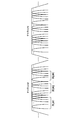
- FIG. 2 is a diagram illustrating an outline of a method in which the wireless terminals 1 to 4 transmit the BA frame to the access point 11 in the uplink multiuser MIMO.
- Signals (frames) transmitted from the access point 11 and the wireless terminals 1 to 4 are indicated by rectangles.
- the horizontal axis is the time axis, and the right side in the figure is the direction in which time flows.
- a method of using a BA frame as a delivery confirmation response frame will be described, but the same applies to the case of using an ACK frame.
- the access point 11 has established wireless links with a plurality of wireless terminals including the wireless terminals 1 to 4 in advance. Further, the access point 11 obtains in advance downlink channel information from the antennas 12A to 12D to the radio terminals 1 to 4 from the radio terminals 1 to 4. Then, the data addressed to the wireless terminals 1 to 4 held in the buffer is transmitted in downlink multi-user MIMO using data frames 601 to 604.
- Each of the data frames 601 to 604 may be an aggregation frame obtained by aggregating one or more data frames. In the aggregation frame, a plurality of frames are connected to each other through a delimiter, and each frame can be separated by the delimiter on the receiving side.
- the aggregation frame aggregates a plurality of data frames, but the aggregated frame may include a plurality of types of frames such as a data frame and a management frame. Details of frame types such as data frames and management frames will be described in detail in another embodiment.
- the wireless terminals 1 to 4 that have received the data frames 601 to 604 check a CRC (cyclic redundancy code) for the received data frame and check whether the data frame has been received without error. Then, after a predetermined time T1 has elapsed since the downlink multi-user MIMO transmission, BA frames 611 to 614 that are delivery confirmation response frames are transmitted to the access point 11 in the uplink multi-user MIMO transmission.
- CRC cyclic redundancy code
- the fixed time T1 may be an arbitrary value as long as it is a predetermined fixed time.
- SIFS short interframe space
- 16 ⁇ s which is a time interval between frames specified in the IEEE 802.11 wireless LAN MAC protocol specification, may be used, or a longer value may be used. Good.
- the access point 11 Since the access point 11 simultaneously receives the BA frames 611 to 614 transmitted from each wireless terminal by the uplink multiuser MIMO in the same frequency band, it is necessary to spatially separate these BA frames. Therefore, the access point 11 transmits information (spatial separation information) necessary for spatially separating the BA frame to the wireless terminals 1 to 4 in advance.
- the access point 11 transmits information on preamble patterns (bit strings) orthogonal to each other as space separation information to the wireless terminals 1 to 4.
- the wireless terminals 1 to 4 store preamble patterns (bit strings) orthogonal to each other between the wireless terminals in the preamble field of the BA frame transmitted from the wireless terminal.
- the access point 11 knows in advance the preamble pattern of each BA frame, and estimates the uplink channel response from each wireless terminal to the access point 11 using this preamble pattern.
- the access point 11 estimates a channel response matrix (uplink channel response matrix) from the antenna of each wireless terminal to the antenna of the access point 11.
- the access point 11 separates a field (for example, a data field) after the preamble field of the BA frame received from each wireless terminal by using the estimated uplink channel response matrix.
- This can be performed using a known method such as a ZF (Zero-Forcing) method, a MMSE (Minimum Mean Square Error) method, or a maximum likelihood estimation method.
- the access point 11 transmits the space separation information to the wireless terminals 1 to 4 using the MAC header or PHY header of the data frames 601 to 604 to be transmitted by downlink multiuser MIMO.
- FIG. 3 shows an example of a data frame transmitted from the access point 11 to each wireless terminal.
- This data frame includes an FC (Frame Control) field, a Duration / ID field, an RA (Receiver Address) field, a TA (Transmitter Address) field, a common information field, a terminal information field, a Frame Body field, and an FCS (Frame Check Sequence) field.
- FC Fre Control
- Duration / ID field an RA (Receiver Address) field
- TA Transmitter Address
- a common information field a terminal information field
- a Frame Body field includes an FCS (Frame Check Sequence) field.
- FCS Fre Check Sequence
- the FC field stores information indicating the frame type and the like.
- the duration set as virtual carrier sense is stored in the Duration / ID field.
- the RA field stores the MAC address of the frame transmission destination.
- the data frame 601 addressed to the wireless terminal 1 stores the MAC address of the wireless terminal 1.
- the MAC address of the frame transmission source is stored.
- the MAC address of the access point 11 is stored.
- information notified for each wireless terminal is stored as space separation information.
- the data body transmitted from the access point 11 to each wireless terminal is stored.
- FCS information of each data frame is stored.
- the FCS information is used for frame error detection on the wireless terminal side that has received the data frame.
- the spatial separation information notified by the access point 11 using the common information field and the terminal information field will be described.
- the access point 11 transmits an orthogonal matrix as spatial separation information so that each wireless terminal performs uplink multiuser MIMO transmission using preamble patterns orthogonal to each other.
- An example of the orthogonal matrix is shown below.
- Matrix (1) is an example of an orthogonal matrix (that is, a 2 ⁇ 2 matrix) when the spatial multiplexing number is 2.
- the matrix (2) is an example of an orthogonal matrix (that is, a 4 ⁇ 4 matrix) when the spatial multiplexing number is 4 (corresponding to the example of FIG. 1).
- the orthogonal matrix has a property that row (or column) vectors representing each row (or each column) are orthogonal to each other.
- An orthogonal vector means that the inner product is zero.
- the spatial multiplexing number is the number of streams to be spatially multiplexed.
- the access point 11 transmits the orthogonal matrix to the wireless terminals 1 to 4 using the common information field.
- the access point 11 may transmit the number of uplink multi-user MIMO transmission streams by the wireless terminals 1 to 4 and an orthogonal matrix corresponding to the number.
- orthogonal matrices of 4 and the matrix (2) are stored in the common information field.
- the wireless terminals 1 to 4 In order for the wireless terminals 1 to 4 to transmit preamble patterns orthogonal to each other, it is necessary to specify the preamble pattern used by each wireless terminal in the terminal information field.
- the row number (or column number) of the orthogonal matrix can be used.
- the row number (or column number) used by the wireless terminal 1 is stored in the terminal information field of the data frame transmitted to the wireless terminal 1.
- the wireless terminal 1 can specify the preamble pattern to be used based on the row (or column) of the number stored in the terminal information field.
- the access point 11 sets the total number of streams in the common information field. Just send it.
- the wireless terminals 1 to 4 can read the matrix stored in the internal memory with reference to the total number of streams designated from the access point 11.
- the terminal information field may include space separation information used by other wireless terminals. For example, information on preamble patterns used not only by the wireless terminal 1 but also by the wireless terminals 2 to 4 may be stored in the terminal information field of the data frame transmitted to the wireless terminal 1. Further, a plurality of terminal information fields each having an identifier of each wireless terminal such as a terminal information field for the wireless terminal 1 and a terminal information field for the wireless terminal 2 may be provided.
- the frame format in FIG. 3 is an example, and other formats may be used.
- the common information field and the terminal information field may be interchanged, or the position where these fields are inserted may be changed.
- Another field in which the common information field and the terminal information field are integrated may be provided.
- the space separation information may be stored in a reserved area of another field.
- FIG. 4 shows an example of a PHY header of a data frame transmitted from the access point 11 to the wireless terminals 1 to 4.
- PHY header includes L-STF (Legacy-Short Training Field), L-LTF (Legacy-Long Training Field), L-SIG (Legacy Signal Field), common information field, and terminal information field.
- L-STF Legacy-Short Training Field
- L-LTF Legacy-Long Training Field
- L-SIG Legacy Signal Field
- L-STF, L-LTF, and L-SIG are fields that can be recognized by legacy standards such as IEEE 802.11a, and store information such as signal detection, frequency correction, and transmission speed.
- the access point 11 stores the space separation information in the common information field and the terminal information field in association with the Group ID and user position specified for realizing downlink multi-user MIMO transmission in the IEEE 802.11ac standard. Also good.
- the access point 11 transmits data frames 601 to 604 to the wireless terminals 1 to 4 in the downlink multi-user MIMO transmission
- the field from the L-STF to the common information field is transmitted without beamforming.
- These fields may be transmitted with beamforming. That is, the field storing the same information for the wireless terminals 1 to 4 can be transmitted without using beamforming.
- a plurality of or one antenna may be used.
- the frame format in FIG. 4 is an example, and other formats may be used.
- the common information field and the terminal information field may be interchanged, or the position where these fields are inserted may be changed.
- Another field in which the common information field and the terminal information field are integrated may be provided.
- the space separation information may be stored in a reserved area of another field.
- the wireless terminals 1 to 4 check the CRC for the data frame received from the access point 11, and check whether the data frame has been received without error. Then, after a lapse of a predetermined time T1, a BA frame that is a delivery confirmation response frame is transmitted to the access point 11 by uplink multiuser MIMO. At this time, each wireless terminal refers to the spatial separation information notified from the access point 11 and selects a preamble pattern (bit string) to be set in the preamble field of the BA frame.
- FIG. 5 shows an example of BA frames 611 to 614 (more specifically, PHY packets including BA frames) transmitted by the wireless terminals 1 to 4.
- the CRC result for the data frame received from the access point 11 is stored using the starting sequence number (Starting Sequence Number) and the bitmap. Further, the values of the RA field and TA field are set according to the transmission destination and the transmission source.
- the preamble field 501 stores a preamble pattern (bit string) generated using orthogonal row examples.
- the wireless terminal 1 is in the first row of the matrix (2)
- the wireless terminal 2 is in the second row of the matrix (2)
- the wireless terminal 3 is in the matrix (2) based on the spatial separation information notified from the access point 11.
- the wireless terminal 4 assumes that the fourth line of the matrix (2) is designated as a preamble pattern.
- the preamble field 501 is composed of a plurality of sections, and in each section, “P” or “ ⁇ P” is arranged according to the value of the corresponding row of the orthogonal matrix along the frame direction.
- One section corresponds to at least one or more modulation symbols.
- One section corresponds to a symbol period.
- the symbol modulation method may be any method such as BPSK, QPSK, or QAM.
- P and “ ⁇ P” are elements each composed of a bit string of 1 bit or more. As an example, the modulation symbol of the bit string P and the modulation symbol of ⁇ P have the same amplitude and a phase shifted by 180 degrees (a relationship that cancels each other).
- the preamble pattern of the wireless terminal 1 is [P, -P, P, P], which corresponds to [1, -1, 1, 1] in the first row of the matrix (2).
- the preamble pattern of the wireless terminal 2 is [P, P, -P, P], which corresponds to [1, 1, -1, 1] in the second row of the matrix (2).
- the preamble pattern of the wireless terminal 3 is [P, P, P, ⁇ P], which corresponds to [1, 1, 1, ⁇ 1] in the third row of the matrix (2).
- the preamble pattern of the wireless terminal 4 is [ ⁇ P, P, P, P], which corresponds to [ ⁇ 1, 1, 1, 1] in the fourth row of the matrix (2).
- Preamble patterns between wireless terminals are orthogonal to each other.
- “t1”, “t2”, “t3”, and “t4” represent the timing at which the bit string (P or ⁇ P) of each section of the preamble pattern is transmitted.
- the bit string P in the first section of the preamble pattern of the wireless terminal 1 is transmitted using a modulation symbol (first modulation symbol) corresponding to the modulation scheme.
- the bit string P in the first section of the preamble pattern of the wireless terminals 2 and 3 is transmitted.
- the bit string -P in the first section of the preamble pattern of the wireless terminal 4 is transmitted by a modulation symbol (second modulation symbol, for example, a symbol having the same amplitude and opposite phase as the first modulation symbol) according to the modulation scheme. .
- each wireless terminal configures a preamble pattern based on a different one of each row (or each column) of the orthogonal matrix corresponding to the number of spatial multiplexing (the number of streams), so that preamble patterns orthogonal between wireless terminals are formed.
- the frame format in FIG. 5 is an example, and other formats may be used.
- the preamble pattern may be stored in a reserved area of another field.
- the uplink channel responses from the antennas 1A to 4A of the wireless terminals 1 to 4 to the antennas 12A to 12D of the access point 11 are h11 to h14, h21 to h24, h31 to h34, respectively. It is expressed as h41 to h44.
- the bit string “P” in the first section of the preamble pattern is the first modulation symbol and the bit string “ ⁇ P” is the first at the timing t1 shown in FIG. It is transmitted with 2 modulation symbols.
- the first modulation symbol signal “P” transmitted from the antenna 1A of the wireless terminal 1 is propagated to the antenna 12A, the propagation path response h11 to the access point 11, the propagation path response h12 to the antenna 12B, and the propagation to the antenna 12C.
- the signals are received by the respective antennas 12A to 12D under the influence of the path response h13 and the propagation path response h14 to the antenna 12D.
- the first modulation symbol signal transmitted from the antennas 2A and 3A of the wireless terminals 2 and 3 and the second modulation symbol signal transmitted from the antenna 4A of the wireless terminal 4 are also affected by the propagation path responses, and the access point. 11 antennas 12A to 12D.
- the access point 11 can obtain the propagation path responses h11, h21, h31, and h41 by adding or subtracting the received signals t1A, t2A, t3A, and t4A of the antenna 12A.
- h11 (t1A-t2A + t3A + t4A) / 4P. Since P is a known signal and the received signals t1A, t2A, t3A, and t4A can be measured, h11 can be obtained.
- h21, h31, and h41 can be obtained by adding or subtracting the received signals t1A, t2A, t3A, and t4A.
- the access point 11 determines the propagation path response matrix (uplink propagation path) shown in (3) below. Response matrix).
- the four streams transmitted from the antennas 1A to 4A of the radio terminals 1 to 4 can be separated. That is, the access point 11 can spatially separate data arranged after the preamble field 501 of the BA frame received from the wireless terminals 1 to 4.
- an uplink channel response matrix is obtained on the access point 11 side.
- each access point 11 can estimate an uplink channel response matrix by configuring a preamble pattern using the matrix (1).
- the wireless terminal that performs the MIMO transmission determines each stream to be transmitted based on its own judgment.
- different patterns can be applied.
- uplink multi-user MIMO since wireless terminals that transmit streams are different, it is not possible to know which row (or column) based on the orthogonal matrix is used by other wireless terminals.
- the access point 11 determines that the preamble patterns used by the wireless terminals are different from each other, and information (spatial separation information) regarding the preamble pattern to be used by each wireless terminal is stored in the data frames 601 to 604. In the common information field and terminal information field. Thereby, it can be ensured that each wireless terminal uses a different preamble pattern.
- Each wireless terminal uses a preamble pattern designated for its own device. Since the preamble patterns of the BA frame received from each wireless terminal at the access point 11 are orthogonal to each other, the access point 11 can estimate the uplink channel response matrix. The access point 11 can spatially separate data after the preamble field of each BA frame using the uplink channel response matrix.
- the access point 11 is equipped with a wireless communication device (see FIG. 7 described later).
- the wireless communication apparatus includes a wireless communication unit 105, a control unit 101, and a buffer 104.
- the control unit 101 in the access point 11 controls communication with the plurality of wireless terminals 1 to 4.
- each wireless terminal is also equipped with a wireless communication device (see FIG. 8 described later).
- the wireless communication apparatus includes a wireless communication unit 205 and a control unit 201.
- the control unit 201 in the wireless terminal controls communication with the access point 11.
- the access point 11 may be connected to another wired or wireless network (referred to as a second network) separately from a wireless network (referred to as a first network) formed with each wireless terminal.
- the access point 11 relays communication between the first network and the second network and between wireless terminals.
- the access point 11 receives frames addressed to the wireless terminals 1 to 4 from the second network or the wireless terminals of the first network, and holds them in the buffer.
- FIG. 7 is a functional block diagram of the wireless communication device of the access point 11. This figure shows the configuration of the wireless communication device on the first network side.
- the wireless communication apparatus includes a control unit 101, a transmission unit 102, a reception unit 103, antennas 12A, 12B, 12C, and 12D, and a buffer 104.
- the control unit 101 corresponds to a control unit or a baseband integrated circuit that controls communication with a wireless terminal, and the transmission unit 102 and the reception unit 103 correspond to a wireless communication unit 105 or an RF (Radio Frequency) integrated circuit, for example.
- the processing of the control unit 101 may be performed by software (program) that operates on a processor such as a CPU, may be performed by hardware, or may be performed by both of the software and hardware. .
- the control unit 101 may have either a configuration including the buffer 104 or a configuration not including the buffer 104 (including in FIG. 7).
- the wireless communication device may include an internal memory that stores space separation information and the like. Further, it may be connected to an external memory for storing space separation information and the like.
- the buffer 104 is a storage unit for transferring data between the upper layer and the control unit 101.
- the upper layer stores a frame received from the second network in the buffer 104 for relay to the first network, and receives a frame received from the first network from the control unit 101.
- the upper layer may perform communication processing above the MAC layer such as TCP / IP and UDP / IP. Further, the upper layer may perform processing of an application layer that processes data.
- the upper layer operation may be performed by software (program) processing by a processor such as a CPU, may be performed by hardware, or may be performed by both software and hardware.
- the control unit 101 mainly performs MAC layer processing and part of physical layer processing (for example, MIMO-related processing).
- the control unit 101 controls communication with each wireless terminal in the first network by transmitting and receiving frames via the transmission unit 102 and the reception unit 103. Further, the control unit 101 may perform control so that a Beacon frame is periodically transmitted.
- the control unit 101 may include a clock generation unit.
- the control unit 101 may be configured to receive a clock from the outside.
- the control unit 101 may manage the internal time according to the clock.
- the clock generated by the clock generation unit may be output to the outside.
- the control unit 101 receives an association request from a wireless terminal and establishes a wireless link with the wireless terminal through a process such as authentication as necessary.
- the control unit 101 periodically checks the buffer 104.
- the control unit 101 confirms the buffer 104 by an external trigger such as the buffer 104.
- the control unit 101 sets data frames 601 to 601 addressed to each wireless terminal in which space separation information is set in the common information field, the terminal information field, or both. 604 is generated.
- the control unit 101 reads a frame addressed to each wireless terminal from the buffer 104, performs a MAC layer process, and sends the frame to the transmission unit 102. Further, the control unit 101 calculates a transmission weight of each transmission system based on downlink propagation path information acquired in advance from each wireless terminal, and sends the transmission weight to each transmission system of the transmission unit 102. The transmission unit 102 acquires transmission weight information for each transmission system. The transmission unit 102 modulates each frame for each transmission system, and multiplies the modulated signal by a transmission weight according to the transmission system.
- Each transmission system performs physical layer processing such as adding a PHY header to each multiplication signal, and performs DA conversion and filter processing to extract a signal component in a desired band for each frame after processing of the physical layer , Perform frequency conversion (up-conversion). Further, each transmission system amplifies the frequency-converted signal and radiates it as a radio wave from the corresponding antenna. Thereby, downlink multiuser MIMO transmission to each wireless terminal is performed.
- the signal received by each antenna is processed in the receiving unit 103 for each reception system corresponding to the antenna.
- BA frames 611 to 614 transmitted from a plurality of wireless terminals are received simultaneously by each antenna (uplink multiuser MIMO reception).
- the reception signal of each antenna is input to each reception system in the reception unit 103.
- Each received signal is amplified in the receiving system, frequency-converted (down-converted), and a desired band component is extracted by filtering processing.
- the extracted signals are further converted into digital signals by AD conversion, and after undergoing physical layer processing such as demodulation, are input to the control unit 101 respectively.
- the control unit 101 obtains an uplink channel response matrix by performing channel estimation based on a preamble pattern of a signal input from each reception system. Based on the uplink propagation path response matrix obtained by estimation, the control unit 101 separates the data portion after the preamble field for each wireless terminal (for each BA frame), and reads the CRC result from each data portion.
- processing up to the digital area may be performed by the control unit 101, and processing after DA conversion may be performed by the transmission unit 102.
- processing up to A / D conversion is performed by the receiving unit 103, and processing of the digital area including subsequent physical layer processing is performed by the control unit 101. May be. Carvings other than those described here may be performed.
- FIG. 8 is a functional block diagram of a wireless communication device mounted on the wireless terminal 1. Since the wireless communication devices mounted on the wireless terminals 2 to 4 have the same configuration as the wireless terminal 1, the description of the wireless terminal 1 will be replaced with the description of the wireless terminals 2 to 4 below.
- the wireless communication apparatus includes a control unit 201, a transmission unit 202, a reception unit 203, an antenna 1A, and a buffer 204.
- the control unit 201 corresponds to a control unit or a baseband integrated circuit that controls communication with the access point 11, and the transmission unit 202 and the reception unit 203 correspond to the wireless communication unit 205 or the RF integrated circuit, for example.
- the processing of the control unit 201 may be performed by software (program) that operates on a processor such as a CPU, may be performed by hardware, or may be performed by both of these software and hardware. .
- the control unit 201 may have either a configuration including the buffer 104 or a configuration not including the buffer 104 (including in FIG. 8).
- the wireless communication device may include an internal memory that stores space separation information and the like. Further, it may be connected to an external memory for storing space separation information and the like.
- the buffer 204 is a storage unit for transferring data frames between the upper layer and the control unit 201.
- the upper layer generates a frame to be transmitted to another wireless terminal, the access point 11, or a device on another network such as a server, and stores the frame in the buffer 204 or receives the frame received by the first network in the buffer 204. Or receive through.
- the upper layer may perform communication processing above the MAC layer such as TCP / IP and UDP / IP. Further, the upper layer may perform processing of an application layer that processes data.
- the upper layer processing may be performed by software (program) that operates on a processor such as a CPU, may be performed by hardware, or may be performed by both of the software and hardware.
- the control unit 201 mainly performs MAC layer processing.
- the control unit 201 controls communication with the access point 11 by transmitting and receiving frames to and from the access point 11 via the transmission unit 202 and the reception unit 203.
- the control unit 201 receives a Beacon frame periodically transmitted from the access point 11 via the antenna 1A and the reception unit 203.
- the control unit 201 may include a clock generation unit.
- the control unit 201 may be configured to receive a clock from the outside.
- the control unit 201 may manage the internal time by the clock.
- the clock generated by the clock generation unit may be output to the outside.
- the control unit 201 receives a Beacon frame, makes an association request to the access point 11, and establishes a wireless link with the access point 11 through a process such as authentication as necessary.
- the control unit 201 periodically checks the buffer 204.
- the control unit 201 confirms the buffer 204 by an external trigger such as the buffer 204.
- the control unit 201 reads the frame and transmits the frame via the transmission unit 202 and the antenna 1A according to the communication method to be used.
- the transmission unit 202 performs desired physical layer processing such as modulation processing and addition of a PHY header to the frame input from the control unit 201.
- DA conversion filter processing for extracting a signal component in a desired band
- frequency conversion up-conversion
- the signal received by the antenna 1A is processed by the receiving unit 203.
- a signal of the data frame 601 transmitted from the access point 11 to the wireless terminal 1 is received and processed by the receiving unit 203.
- the reception signal is amplified by the reception unit 203, subjected to frequency conversion (down-conversion), and a desired band component is extracted by a filering process.
- Each extracted signal is further converted into a digital signal by AD conversion, subjected to physical layer processing such as demodulation, and then input to the control unit 201.
- the control unit 201 reads the space separation information stored in the common information field and the terminal information field of the data frame 601.
- the preamble pattern to be used is specified based on the information.
- the preamble pattern may be used.
- the control unit 101 performs control so that a BA frame is transmitted after a predetermined time from the reception of the data frame 601.
- the control unit 101 performs a CRC check on the received data frame, and generates a BA frame storing information representing the CRC result.
- the specified preamble pattern is stored in the preamble field of the BA frame.
- the transmission unit 102 modulates the generated BA frame, and performs physical layer processing such as addition of a PHY header to the modulated signal. Further, DA conversion, filter processing for extracting a signal component in a desired band, and frequency conversion (up-conversion) are performed on the frame after processing in the physical layer.
- the transmitter 102 amplifies the frequency-converted signal and radiates it as a radio wave from any one antenna to the space.
- processing up to the digital area may be performed by the control unit 201, and processing after DA conversion may be performed by the transmission unit 202.
- processing up to AD conversion is performed by the reception unit 203, and the processing of the digital area including the subsequent physical layer processing is performed by the control unit 201. Good. Carvings other than those described here may be performed.
- the buffers 104 and 204 may be a volatile memory such as a DRAM or a non-volatile memory such as a NAND or MRAM. Further, the internal memory and the external memory may be an SSD, a hard disk or the like in addition to the volatile memory and the non-volatile memory.
- FIG. 9 is a flowchart of a basic operation example of the control unit 101 mounted on the access point 11 according to the present embodiment.
- step S1 the control unit 101 generates space separation information to be stored in the common information field and the terminal information field of the data frames 601 to 604.
- the rules for specifying the orthogonal matrix and preamble pattern are stored in the internal memory, they are read from the internal memory.
- step S2 the control unit 101 stores the spatial separation information generated in step S1 in the common information field and the terminal information field of the data frames 601 to 604, and transmits them by spatial multiplexing via the wireless communication unit 105 (downlink multiple). User MIMO transmission).
- step S3 the control unit 101 receives the BA frames 611 to 614 corresponding to the data frames 601 to 604 via the wireless communication unit 105.
- the BA frames 611 to 614 are transmitted from the wireless terminals 1 to 4 by spatial multiplexing (uplink multiuser MIMO transmission).
- step S4 the control unit 101 refers to the preamble field 501 of the received BA frames 611 to 614 and spatially separates the BA frames.
- FIG. 10 is a flowchart of a basic operation example of the control unit 201 installed in the wireless terminal according to the present embodiment.
- step S11 the control unit 201 receives a data frame addressed to itself through the wireless communication unit 205.
- the data frame is transmitted from the access point 11 by spatial multiplexing.
- step S12 the control unit 201 acquires space separation information from the received data frame.
- the acquired space separation information can be stored in an internal memory.
- step S13 the control unit 201 generates a BA frame based on the space separation information acquired in step S13.
- the preamble field of the BA frame the preamble pattern specified by the space separation information is set.
- step S14 the control unit 201 transmits the BA frame via the wireless communication unit 205.
- the wireless terminals 1 to 4 simultaneously transmit BA frames using the same frequency band (uplink multiuser MIMO transmission).
- each wireless terminal transmits an acknowledgment response frame in uplink multiuser MIMO. This shortens the delivery confirmation time for the data frame transmitted by the downlink multiuser MIMO, thereby improving the throughput.
- the access point notifies each wireless terminal in advance of information necessary for transmitting an acknowledgment response frame in uplink multiuser MIMO transmission.
- the access point can separate the delivery confirmation response frames transmitted by the uplink multiuser MIMO from the plurality of wireless terminals.
- the access point 11 transmits the spatial separation information to the wireless terminals 1 to 4 using the MAC header or PHY header of the data frames 601 to 604.
- a method for transmitting space separation information using a notification frame other than a data frame for downlink multiuser MIMO transmission will be described.
- FIG. 11 shows an example of a Group ID Management frame with space separation information.
- This frame includes a Membership Status Array field, a User Position Array field, a common information field, and a terminal information field.
- a Group ID is assigned to each of a plurality of wireless terminals that are targets of the same multiuser transmission as a method for realizing downlink multiuser MIMO transmission.
- the Membership Status Array field is a field for notifying which group the wireless terminal that is the transmission destination of the Group ID Management frame with space separation information belongs. In FIG. 11, affiliation information regarding the groups of Group IDs 0 to 63 is notified. For example, if “Membership Status In Group ID 1” in the Membership Status Array field is “0”, this indicates that this wireless terminal does not belong to Group ID1, and if “1”, it belongs to Group ID1. Represents that.
- the User Position Array field is a field for notifying the user position of the wireless terminal in each group.
- the user positions in the groups with Group IDs 0 to 63 are notified. For example, if “User Position In Group ID 1” in the User Position Array field is “1”, it indicates that the user position of the wireless terminal in Group ID 1 is “1”.
- the wireless terminal can belong to a plurality of groups, and at this time, the user position can be different for each group.
- information commonly notified to the wireless terminals 1 to 4 and information notified for each wireless terminal are stored as space separation information.
- an orthogonal matrix such as matrix (1) or (2) can be stored.
- the access point 11 may store different orthogonal matrices for each Group ID. For example, notify Group (1) to Group ID1 with 2 wireless terminals belonging to the group, and notify 2x2 matrix different from Matrix (1) to Group ID3 with 2 wireless terminals belonging to the group. Can do.
- the matrix (2) is notified to the Group ID3 having four wireless terminals belonging to the group.
- the row number (or column number) of the orthogonal matrix is stored as an example of specifying the preamble pattern for each wireless terminal.
- the access point 11 may change the designated preamble pattern according to the user position of the wireless terminal.
- the user position “0” can be designated as the first row of the matrix (1)
- the user position “1” can be designated as the second row of the matrix (1).
- specify the preamble pattern by combining the Group ID and the user position, such as the first line of the matrix (1) for Group ID1 user position 1 and the second line for Group ID2 user position 1. May be.
- the access point 11 transmits a Group ID Management frame with spatial separation information to the wireless terminals 1 to 4 before transmitting the data frames 601 to 604 to the downlink multiuser MIMO.
- the transmission of the Group ID Management frame with space separation information is performed by unicast as an example.
- the access point 11 can transmit a Group ID Management frame with space separation information at the time of association.
- a Group ID Management frame with space separation information with updated space separation information may be transmitted again.
- the access point 11 may store Group IDs, user positions, and space separation information for a plurality of wireless terminals in a Group ID Management frame with space separation information. In this case, the access point 11 can transmit a Group ID Management frame with space separation information by broadcast or multicast.
- the frame format in FIG. 11 is an example, and other formats may be used.
- the common information field and the terminal information field may be interchanged, or the position where these fields are inserted may be changed.
- Another field in which the common information field and the terminal information field are integrated may be provided.
- the space separation information may be stored in a reserved area of another field.
- the space separation information is added to the Group ID Management frame defined in the IEEE 802.11 standard.
- a frame (notification frame) for notifying the space separation information may be newly defined.
- addresses corresponding to the transmission source and the transmission destination can also be stored in the Group ID Management frame with space separation information and the newly defined notification frame.
- a Group ID Management frame with space separation information may be transmitted to the wireless terminals 1 to 4 after the data frames 601 to 604 are transmitted to the wireless terminals 1 to 4 by downlink multiuser MIMO. At this time, any of the method of unicasting the group ID management frame with space separation information for each terminal and the method of broadcasting or multicasting as described above are possible.
- the timing at which the radio terminals 1 to 4 perform uplink multiuser MIMO transmission may be determined by an arbitrary method.
- the transmission timing may be a predetermined time after the completion of reception of the Group ID Management frame with space separation information.
- the time elapsed from the completion of reception of the data frames 601 to 604 may be determined in consideration of the time required for transmitting the Group ID Management frame with space separation information. Or you may set the information regarding the timing which performs uplink multiuser MIMO transmission to a common information field.
- the terminal determines the uplink multiuser MIMO transmission timing according to the information, and when the information is not set, the uplink multiuser MIMO transmission timing is determined by a predetermined method. It is also possible to determine the user MIMO transmission timing (for example, the transmission timing is a predetermined time after the completion of reception of the data frame transmitted by the downlink multi-user). It may be determined by methods other than those described here.
- the access point 11 After transmitting the Group ID Management frame with space separation information, the access point 11 transmits data frames 601 to 604 in downlink multiuser MIMO.
- the access point 11 can store the Group ID to which the wireless terminals 1 to 4 belong and the number of streams for each user position in the PHY header or MAC header of the data frames 601 to 604.
- the wireless terminals 1 to 4 that have received the data frame check the CRC of the data frame received from the access point 11 as in the first embodiment, and check whether the data frame has been received without error. Then, after a lapse of a certain time T1, a BA frame is transmitted as uplink multiuser MIMO to the access point 11.
- each wireless terminal refers to the group ID stored in the PHY header or MAC header of the data frame and the space separation information previously notified in the group ID management frame with space separation information, and refers to the preamble field of the BA frame. Select the preamble pattern (bit string) to be set.
- each wireless terminal can identify the preamble pattern by referring to the user position information for each Group ID notified in the Group ID Management frame with space separation information. .
- FIG. 12 is a flowchart of a basic operation example of the control unit 101 mounted on the access point 11 according to the present embodiment.
- step S21 the control unit 101 generates space separation information to be stored in the common information field and the terminal information field of the data frames 601 to 604.
- the rules for specifying the orthogonal matrix and preamble pattern are stored in the internal memory, they are read from the internal memory.
- step S22 the control unit 101 generates a group ID management frame (notification frame) with space separation information in which the space separation information generated in step S21 is stored in the common information field and the terminal information field, and passes through the wireless communication unit 105. To send.
- a group ID management frame notification frame
- step S23 the control unit 101 transmits data frames 601 to 604 by spatial multiplexing (downlink multiuser MIMO transmission) via the wireless communication unit 105.
- spatial multiplexing downlink multiuser MIMO transmission
- step S24 the control unit 101 receives the BA frames 611 to 614 corresponding to the data frames 601 to 604 via the wireless communication unit 105.
- the BA frames 611 to 614 are transmitted from the wireless terminals 1 to 4 by spatial multiplexing (uplink multiuser MIMO transmission).
- step S25 the control unit 101 refers to the preamble field 501 of the received BA frames 611 to 614 and spatially separates the BA frames.
- FIG. 13 is a flowchart of a basic operation example of the control unit 201 installed in the wireless terminal according to the present embodiment.
- step S31 the control unit 201 receives a group ID management frame (notification frame) with space separation information transmitted from the access point 11 via the wireless communication unit 205.
- the control unit 201 acquires the space separation information from the received Group ID Management frame with space separation information.
- step S32 the control unit 201 receives a data frame addressed to itself through the wireless communication unit 205.
- the data frame is transmitted from the access point 11 by spatial multiplexing.
- step S33 the control unit 201 generates a BA frame based on the space separation information acquired in step S31.
- the preamble field of the BA frame the preamble pattern specified by the space separation information is set.
- step S34 the control unit 201 transmits a delivery confirmation response frame via the wireless communication unit 205.
- the wireless terminals 1 to 4 simultaneously transmit a delivery confirmation response frame using the same frequency band (uplink multiuser MIMO transmission).
- the access point notifies each wireless terminal in advance of information necessary for uplink acknowledgment multi-user MIMO transmission of a delivery confirmation response frame before transmitting the data frame. .
- the access point can separate the delivery confirmation response frames transmitted by the uplink multiuser MIMO from the plurality of wireless terminals.
- one stream is transmitted from each wireless terminal that performs uplink multiuser MIMO transmission.
- downlink multiuser MIMO transmission from the access point to each wireless terminal is also one stream each.
- an embodiment in which there is a wireless terminal capable of transmitting or receiving two or more streams, that is, a wireless terminal capable of MIMO transmission or reception is shown.
- FIG. 14 (A) and FIG. 14 (B) show an example of a wireless communication system when there are wireless terminals capable of transmitting and receiving two or more streams, that is, wireless terminals capable of MIMO transmission and reception.
- the wireless terminal 1 includes three antennas, and the wireless terminal 2 includes one antenna.
- the wireless terminal 1 receives 3 streams from the access point 11 by MIMO, and the wireless terminal 2 receives 1 stream from the access point 11.
- each of the wireless terminal 1 and the wireless terminal 2 includes two antennas, and each receives two streams from the access point 11 by MIMO.
- the total number of streams in the downlink multiuser MIMO from the access point 11 is four.
- the user multiplexing number in the downlink is 4, whereas in the examples of FIGS. 14A and 14B, the user multiplexing number is 2.
- the block configuration of the wireless communication device installed in the wireless terminal capable of MIMO is the same as that shown in FIG. Since the configuration and operation are obvious from the description of the MIMO operation of the access point so far, the description is omitted.
- the wireless terminal 1 of FIG. 14A and the wireless terminals 1 and 2 of FIG. 14B receive multi-user MIMO transmission of BA frames in one stream after receiving data frames from the access point 11 in a plurality of streams. Can do.
- the number of downlink multiuser MIMO streams is 4, whereas the number of uplink multiuser MIMO streams is 2. That is, the number of streams in the uplink is equal to the number of multiplexed users in the downlink.
- the transmission of the BA frame in the uplink multi-user MIMO by each wireless terminal 1 stream can be defined by, for example, the IEEE 802.11 standard.
- the access point 11 sets the user multiplexing number and the corresponding orthogonal matrix in the common information field, and the orthogonal matrix used by each wireless terminal in the terminal information field.
- Row numbers (or column numbers) can be stored. For example, in FIG. 14A, since the number of multiplexed users is 2, the matrix (1) is set in the common information field, “wireless terminal 1 is the first row, wireless terminal 2 is the second row”, etc. Can be stored.
- the method described in the first and second embodiments (MAC header, PHY header, Group ID Management frame with space separation information) can be used.
- the wireless terminals 1 and 2 identify the preamble pattern used by the terminal based on the spatial separation information notified from the access point 11, and each of the BA frames corresponding to the data frames received in a plurality of streams is uplink-multiplexed in one stream.
- User MIMO transmission Since the method for specifying and using the preamble pattern is the same as in the first and second embodiments, the description thereof is omitted.
- the access point 11 can notify preamble pattern information for each user position as space separation information.
- the number of wireless terminals belonging to Group ID 1 is 4, the total number of downlink multi-user MIMO transmission streams is 5, and the number of downlink streams for wireless terminals belonging to user positions 0 to 3 is 2, 0, 2, 1 respectively.
- the wireless terminal at user position 1 does not transmit a data frame
- the wireless terminals belonging to user positions 0, 2 and 3 that have received the data frame transmit the BA frame in one stream each in uplink multiuser MIMO transmission. To do.
- the access point 11 notifies the user multiplexing number 3 and the corresponding 3 ⁇ 3 orthogonal matrix as space separation information in the common information field, and the row number (or column number) used by each wireless terminal is the terminal information field. You can notify at.
- Each wireless terminal uses the space separation information designated by the access point 11 to specify the preamble pattern used by each terminal.
- rules such as assigning row numbers of orthogonal matrices in ascending order from wireless terminals with a small user position may be defined.
- the access point 11 may notify the 3 ⁇ 3 orthogonal matrix and the number of downlink streams for each user position as the spatial separation information.
- each wireless terminal can grasp the number of multiplexed users and specify the preamble pattern used by the own device. For example, the number of wireless terminals belonging to Group ID 1 is 4, the total number of downlink multi-user MIMO transmission streams is 5, and the number of downlink streams for wireless terminals belonging to user positions 0 to 3 is 2, 0, 2, 1 respectively.
- the wireless terminal belonging to user position 0 is the first row of the 3 ⁇ 3 matrix
- the wireless terminal belonging to user position 2 is the second row of the 3 ⁇ 3 matrix
- the wireless terminal belonging to user position 3 is the third row of the 3 ⁇ 3 matrix, etc.
- a preamble pattern can be specified. Note that when the matrix values are predetermined in the IEEE 802.11 standard and the wireless terminals 1 to 4 store the values in the internal memory, the access point 11 can transmit the matrix values to the wireless terminals 1 to 4. There is no need to send a value.
- the wireless terminals 1 to 4 can read the corresponding matrix from the internal memory by referring to the uplink user multiplexing number (total stream number) notified explicitly or implicitly from the access point 11. As an example of an implicit notification, the access point 11 notifies the number of downlink streams for each user position.
- Each wireless terminal can acquire the number of multiplexed users (total number of streams) in the uplink by counting the number of wireless terminals whose number of streams is other than 0.
- the wireless terminals 1 and 2 shown in FIGS. 14A and 14B can transmit BA frames using the same number of streams as the streams received from the access point 11. For example, in the case of FIG. 14A, the wireless terminal 1 transmits a BA frame with three streams, and the wireless terminal 2 transmits a BA frame with one stream.
- the access point 11 gives the wireless terminals 1 and 2 the total number of streams in the uplink in the common information field and the corresponding orthogonal matrix, and the row number (or column) of the orthogonal matrix used by each wireless terminal in the terminal information field. Number).
- the matrix (2) is set in the common information field, and “wireless terminal 1 is in the first and second rows, wireless terminal 2 is set in the terminal information field.
- the method described in the first and second embodiments (MAC header, PHY header, Group ID Management frame with space separation information) can be used.
- the wireless terminals 1 and 2 identify the preamble pattern used by the terminal based on the spatial separation information notified from the access point 11, and uplink multi-user MIMO transmission of BA frames using the same number of streams as the received data frames. can do.
- the access point 11 may notify the number of streams used when each wireless terminal performs uplink multiuser MIMO transmission as space separation information. For example, in FIG. 14B, information such as “wireless terminal 1 has one stream and wireless terminal 2 has two streams” is notified. For the notification of the number of streams, a common information field, a terminal information field, or other fields can be used.
- the wireless terminals 1 and 2 determine the number of streams when transmitting the BA frame according to the notified number of streams. At that time, it is also possible to notify transmission of one stream such as “one stream for the wireless terminal 1 and one stream for the wireless terminal 2”.
- the total number of streams specified by the access point 11 can be adjusted within a range not exceeding the reception capability (number of antennas) of the access point 11. Also, the number of streams designated for each wireless terminal can be adjusted within a range not exceeding the reception capability (number of antennas) of each wireless terminal.
- the number of wireless terminals belonging to Group ID 1 is 4, the total number of downlink multi-user MIMO transmission streams is 5, and the number of downlink streams for wireless terminals belonging to user positions 0 to 3 is 2, 0, 2, 1 respectively.
- the wireless terminal at user position 1 does not transmit a data frame
- the wireless terminals belonging to user positions 0, 2, and 3 transmit the BA frames in 2 streams, 2 streams, and 1 stream, respectively, as uplink multi-user MIMO.
- a rule may be defined such that the orthogonal matrix row numbers are assigned in ascending order from wireless terminals with a small user position, and each wireless terminal may specify a preamble pattern based on this rule.
- the access point 11 can transmit the matrix values to the wireless terminals 1 to 4. There is no need to send a value.
- the wireless terminals 1 to 4 can read the corresponding matrix from the internal memory with reference to the total number of streams notified directly or indirectly from the access point 11.
- the control unit 101 of the access point 11 uses the common information field to indicate the total number of streams (explicitly or implicitly) when transmitting the BA frame.
- the number of streams permitted to be transmitted to each wireless terminal can be designated using the terminal information field. It is also possible to specify the number of rows (or column numbers) of the orthogonal matrix in the terminal information field as many as the number of streams permitted to be transmitted to the wireless terminal. Note that the control unit 101 of the access point 11 may acquire the number of streams that can be supported by each wireless terminal from each wireless terminal at the time of association, for example.
- the control unit 101 of the access point 11 may specify the total number of streams in the common information field. Or, if the information of other wireless terminals is included in the terminal information field, the total number of streams can be determined by calculating the total number of row numbers (or column numbers) for each wireless terminal. Explicit notification may be omitted.
- the control unit 101 of the access point 11 sets the row numbers 1, 2, and 3 of the orthogonal matrix in the terminal information field corresponding to the wireless terminal 1. As a result, the wireless terminal 1 recognizes that its own device is permitted to transmit three streams. In addition, the wireless terminal 1 has each row [1, -1, 1, 1], [1, 1, -1, 1], [1] of row numbers 1, 2, and 3 of the orthogonal matrix corresponding to the total number of streams 4. , 1, 1, -1] is used for each stream. As described above, the control unit 101 of the access point 11 may explicitly notify the total number of streams in the common information field, or may omit the notification.
- each terminal information field when the number of streams permitted to be transmitted is explicitly notified in each terminal information field, it is possible to omit the notification of the row number (or column number) of the orthogonal matrix.
- the number of wireless terminal streams corresponding to the terminal information field 1 is 3 and the wireless terminal stream number corresponding to the terminal information field 2 is 1.
- the wireless terminal corresponding to the terminal information field 1 uses the first to third lines of the orthogonal matrix
- the wireless terminal corresponding to the terminal information field 2 uses the fourth line.
- Each wireless terminal adds up the number of streams stored in the terminal information field having a field number smaller than that of its own device, and adds 1 to the total value, so that the row number (or column number) used by the own device is obtained.
- the starting value can be calculated.
- notification of the row number (or column number) used for each wireless terminal can be omitted.
- the common number of streams is specified in the common information field, and the notification of the number of individual streams in each terminal information field is It does not have to be done. Also in this case, the total number of uplink multiuser MIMO streams may be explicitly notified in the common information field. Alternatively, the wireless terminal may grasp the total number of streams from the number of common streams and the number of each terminal information field without performing explicit notification in the common information field.
- each wireless terminal can also use MIMO transmission. If the number of streams allowed to each wireless terminal is not specified, the total number of transmission streams transmitted by uplink multiuser MIMO is transmitted with the number of streams exceeding the capability that can be separated by the access point. Can be. Also, each wireless terminal may not be able to select a preamble pattern that does not overlap with other wireless terminals. In the present embodiment, these problems can be solved by designating the number of streams permitted to each wireless terminal.
- an uplink propagation path response matrix can be estimated at an access point by transmitting preamble patterns orthogonal to each other from each wireless terminal.
- each radio terminal transmits a preamble pattern using orthogonal frequency carriers so that an uplink channel response matrix can be estimated.
- a multi-carrier modulation scheme particularly OFDM (Orthogonal Frequency Division Multiplexing) is used.
- OFDM Orthogonal Frequency Division Multiplexing
- FIG. 15 shows a schematic configuration example of the BA frame according to the present embodiment.
- a schematic configuration example of the BA frame transmitted by the wireless terminals 1 to 4 is shown.
- the BA frame includes a preamble field 501, but the value set as the preamble pattern is different from that in the first embodiment.
- the preamble field 501 of each BA frame is composed of a plurality of sections, and carrier patterns P1, P2, P3, and P4 are assigned to each section in different orders.
- One section corresponds to one OFDM symbol section.
- the carrier pattern P1 represents that a preamble pattern is transmitted using subcarriers f1, f5, and f9 of OFDM modulation.
- the carrier pattern P2 represents that a preamble pattern is transmitted using subcarriers f2, f6, and f10 of OFDM modulation.
- the carrier pattern P3 represents that a preamble pattern is transmitted using subcarriers f3, f7, and f11 of OFDM modulation.
- the carrier pattern P4 represents that a preamble pattern is transmitted using subcarriers f4, f8, and f12 of OFDM modulation.
- the preamble pattern transmitted on each subcarrier may be arbitrary as long as it is known by the access point 11.
- the same data may be used for all subcarriers, or different data may be used for each subcarrier.
- timings t1, t2, t3, and t4 are set in order from the left.
- Timings t1, t2, t3, and t4 represent transmission timings in the corresponding section of the preamble field 501.
- carrier patterns are different from each other in the same timing section. That is, at each of timings t1, t2, t3, and t4, the subcarriers that each wireless terminal uses for transmitting the preamble pattern are orthogonal in frequency. That is, the subcarriers of the wireless terminals do not interfere with each other. In the case of OFDM, since the subcarrier frequencies are selected so that the subcarriers are orthogonal to each other, the subcarriers of each wireless terminal do not interfere with each other unless the same subcarrier is used.
- the subcarrier of the wireless terminal 1 is f1, f5, f9
- the subcarrier of the wireless terminal 2 is f2, f6, f10
- the subcarrier of the wireless terminal 3 is f3, f7, f11
- the subcarrier of the wireless terminal 4 Carriers are f4, f8, and f12. Since the subcarriers do not overlap between the wireless terminals, the subcarriers are orthogonal between the wireless terminals. Similarly, at other timings t2 to t4, the subcarriers are orthogonal between the wireless terminals.
- tone interleaving Since all of P1 to P4 are allocated to the wireless terminals 1 to 4 in different orders, none of the wireless terminals 1 to 4 interfere with each other on all the subcarriers f1 to f12. In this way, switching subcarriers to be used according to a section while using different subcarriers in the same section (timing) between wireless terminals may be referred to as tone interleaving.
- the control unit 201 of the wireless terminal 1 generates an OFDM symbol by assigning a preamble pattern to subcarriers f1, f5, and f9 and assigning, for example, null data to other subcarriers. And send.
- the control unit 201 of the wireless terminal 2 generates and transmits an OFDM symbol by assigning a preamble pattern to the subcarriers f2, f6, and f10 and assigning, for example, null data to the other subcarriers.
- the control unit 201 of the wireless terminal 3 generates and transmits an OFDM symbol by assigning a preamble pattern to the subcarriers f3, f7, and f11 and assigning, for example, null data to the other subcarriers.
- the control unit 201 of the wireless terminal 4 generates and transmits an OFDM symbol by assigning a preamble pattern to the subcarriers f4, f8, and f12 and assigning, for example, null data to the other subcarriers.
- the access point 11 receives the OFDM symbols from the wireless terminals 1 to 4 simultaneously with the respective antennas.
- the receiving unit 103 or the control unit 101 of the access point 11 can acquire a signal for each subcarrier by demodulating the received signal for each antenna. Specifically, for timing t1, subcarriers f1, f5, and f9 for wireless terminal 1, subcarriers f2, f6, and f10 for wireless terminal 2, and subcarriers f3, f7, and f11 for wireless terminal 3 and wireless terminal 4 For, signals for subcarriers f4, f8, and f12 can be acquired. Similarly for other timings t2 to t4, each wireless terminal sequentially generates and transmits OFDM symbols based on different carrier patterns. As a result, the control unit 101 of the access point 11 can acquire signals of all frequency subcarriers f1 to f12 for the wireless terminals 1 to 4, respectively, and can thus estimate the uplink channel response matrix. .
- the control unit 101 of the access point 11 uses the MAC header, the PHY header, and the group ID management frame with space separation information common information of the data frames 601 to 604. Using the field or terminal information field or both of them, it is possible to notify spatial separation information such as the order of carrier patterns for each wireless terminal and the preamble pattern for each subcarrier. Note that notification may be omitted when the preamble pattern is the same for all wireless terminals and all subcarriers.
- notification for each of the carrier patterns P1 to P4, information indicating the correspondence between the number of the subcarrier to be used and the preamble pattern assigned to the subcarrier may be notified in the common information field. Further, information regarding the order of P1 to P4 may be notified in the terminal information field for each wireless terminal.
- the notification method can be expanded or modified in various ways based on the same concept as the above-described embodiment.
- implicit notification may be performed using the number of terminal information fields for each wireless terminal, the number of total transmission streams, and the like. Is possible.
- the preamble pattern may be transmitted using a larger or smaller number of subcarriers.
- the subcarrier for transmitting the data part may be the same subcarrier as the subcarrier for transmitting the preamble pattern, or may be a subcarrier different from these.
- the access point 11 predicts the subcarrier propagation path response for the subsequent data part (MAC frame part) by an arbitrary method from the subcarrier propagation path response that transmitted the preamble pattern. And ask for it. For example, for each subcarrier for the data portion, the same channel response as that closest to the frequency among the subcarriers that transmitted the preamble pattern may be adopted.
- the uplink channel response matrix can be estimated by transmitting a preamble pattern at different timings from each wireless terminal.
- FIG. 16 shows a schematic configuration example of a BA frame in the case where preamble patterns are transmitted at different timings.
- the carrier pattern “P-ALL” represents that a preamble pattern is transmitted using all subcarriers f1 to f12 of OFDM modulation.
- NULL indicates that a preamble pattern is not transmitted.
- the preamble pattern may be arbitrary as long as it is known at the access point 11.
- the access point 11 receives the preamble pattern from the wireless terminal 1 at timing t1, the wireless terminal 2 at t2, the wireless terminal 3 at t3, and the wireless pattern 4 at t4. Thereby, the control unit 101 of the access point 11 can acquire signals of all the frequency subcarriers f1 to f12 for the wireless terminals 1 to 4, and can estimate the uplink channel response matrix.
- the control unit 101 of the access point 11 uses the MAC header, the PHY header, and the group ID management frame with space separation information common information of the data frames 601 to 604. Fields or terminal information fields or both can be used.
- each radio terminal transmits a preamble pattern using orthogonal frequency carriers.
- each wireless terminal transmits a preamble pattern at different timings.
- the access point 11 can estimate the uplink channel response matrix.
- each wireless terminal transmits a BA frame after elapse of a certain time (see T1 in FIG. 2) from reception of the data frames 601 to 604.
- T1 in FIG. 2 the distance between the access point and each wireless terminal is the same, it can be considered that the BA frame transmitted from each wireless terminal is basically received at the same timing at the access point.
- each propagation time is different, so that the wireless terminal that is farther from the access point has a delay in receiving data frames from the access point.
- a BA frame transmitted after a certain time elapses after each wireless terminal receives a data frame causes a delay in the timing at which the wireless terminal is received at the access point as the distance from the access point increases.
- the maximum delay time difference in one direction between the access point and each wireless terminal is ⁇ t
- a guard interval such as OFDM (sometimes called a cyclic prefix).
- the cyclic prefix can be used in a multicarrier modulation scheme other than OFDM or a single carrier modulation scheme, and the present embodiment is not limited to OFDM.
- the reception timing of the BA frame at the access point is adjusted. Specifically, the transmission timing of the BA frame from each wireless terminal is adjusted. This prevents deterioration of the characteristics of uplink multiuser MIMO transmission due to the delay time difference between the access point and each wireless terminal.
- the control unit 101 of the access point 11 communicates with each wireless terminal in advance and estimates the delay time with each wireless terminal before transmitting the data frames 601 to 604.
- the estimation method may be any method, and various existing known techniques can be used.
- a measurement frame is transmitted from the access point 11 and each wireless terminal returns a frame storing the reception time of the measurement frame.
- the control unit 101 of the access point 11 measures the delay time from the difference between the time when the measurement frame is transmitted and the reception time stored in the returned frame.
- a measurement frame is transmitted from the access point 11 and a response frame is received from each wireless terminal. The delay time is measured from the difference between the time when the measurement frame is transmitted and the time when the response frame is received.
- Various methods other than those described here can be used.
- the control unit 101 of the access point 11 of the present embodiment designates a time adjustment amount for adjusting the BA frame transmission timing by the wireless terminal in each terminal information field.
- the control unit 201 of each wireless terminal receives the terminal information field from the access point 11 by the method described in the first to third embodiments, and determines the transmission timing of the BA frame according to the notified time adjustment amount as the reference timing. Accelerate or slow down.
- the reference timing is, for example, a timing after a certain time (see T1 in FIG. 2) after receiving the data frame.
- Each wireless terminal transmits a BA frame at the adjusted transmission timing.
- the time adjustment amount of each wireless terminal set by the access point 11 is determined so that the timing of receiving the BA frame from each wireless terminal is within a certain time delay range.
- the range of the fixed time delay is set at least within the guard interval.
- a delay time with each wireless terminal estimated in advance is used.
- the time adjustment amount of each wireless terminal may be set using a relative time from the transmission timing of the reference wireless terminal.
- a predetermined timing for example, a predetermined time after receiving a data frame
- Wireless terminals other than the reference wireless terminal transmit the BA frame at a timing shifted by the relative time from the transmission timing of the reference wireless terminal.
- the reference wireless terminal may be designated by an arbitrary method.
- designation of a wireless terminal serving as a reference may be included in the common information field.
- a wireless terminal set in a terminal information field having a predetermined number such as the terminal information field 1 may be used as a reference wireless terminal.
- the access point 11 receives the BA frame from each wireless terminal regardless of the communication delay time between the access point 11 and each wireless terminal by controlling the transmission timing of the BA frame. Timing can be kept within a certain range (such as a guard interval).
- the present embodiment is characterized in that the dynamic range of the received power of the BA frame received by the access point from each wireless terminal falls within a certain range.
- the access point 11 simultaneously receives the BA frame from each wireless terminal by the uplink multiuser MIMO. At this time, even if the transmission power of each wireless terminal is the same, if the distance between the access point 11 and each wireless terminal is different, the BA frame is transmitted with different received power due to the difference in the signal attenuation level. There is a possibility of receiving.
- FIG. 17 shows a situation in which the wireless terminals 1 and 2 are arranged at positions close to and far from the access point 11, respectively.
- the distance attenuation amount of the wireless terminal 1 close to the access point 11 is 20 dB
- the distance attenuation amount of the wireless terminal 2 arranged at a position far from the access point 11 is 60 dB.
- the access point 11 simultaneously receives BA frames having a reception power difference of 40 dB.
- the input dynamic range which is the ratio or difference between the maximum and minimum values of received power
- frames with low received power may be buried in quantization noise during AD conversion and may not be received correctly.
- an AD converter having a large number of quantization bits may be employed. However, the number of quantization bits is limited and the cost is increased.
- the above problem is solved by controlling the dynamic range of the received power of the BA frame received from each wireless terminal within a certain range.
- the control unit 101 of the access point 11 communicates with each wireless terminal in advance to estimate the distance attenuation with each wireless terminal.
- the estimation method may be any method, and various existing known techniques can be used.
- the control unit 101 of the access point 11 instructs each wireless terminal to transmit a frame with a specific transmission power, and the received power value of the frame and the distance attenuation amount (uplink distance) from the specific transmission power value. (Attenuation) is estimated.
- the access point 11 transmits a measurement frame with a constant transmission power, and returns a frame storing the received power value of the measurement frame from each wireless terminal.
- the control unit 101 of the access point 11 estimates the distance attenuation amount (downlink distance attenuation amount) based on the transmission power value of the measurement frame and the reception power value stored in the returned frame. Although it is desirable to determine the uplink distance attenuation for the purposes of this embodiment, either distance attenuation may be determined in an environment where there is no significant difference between the downlink and uplink distance attenuation.
- the control unit 101 of the access point 11 is configured so that the reception dynamic range of the BA frame transmitted by the wireless terminal that is a propagation path estimation target is within a certain range.
- the transmission power of the wireless terminal is determined.
- the dynamic range within a certain range is at least within the dynamic range that can be handled by the number of quantization bits of the AD converter mounted on the access point 11.
- the control unit 101 of the access point 11 designates a wireless terminal that is a propagation path estimation target in the terminal information field described in the embodiments so far, and information on transmission power determined for the wireless terminal ( Transmission power information).
- the transmission power information may be represented by the transmission power value itself to be transmitted by each wireless terminal, or may be represented by a relative value with respect to the transmission power (normal transmission power) used for normal transmission.
- the access point 11 determines the transmission power of each wireless terminal, but a configuration in which the transmission power is determined in each wireless terminal is also possible. An example of this will be shown below.
- the control unit 101 of the access point 11 notifies each wireless terminal of the distance attenuation estimated for each wireless terminal in each terminal information field of the data frame.
- the control unit 201 of each wireless terminal determines the transmission power of the BA frame according to the distance attenuation amount notified in each terminal information field. For example, the transmission power is determined so that the reception power of the BA frame at the access point 11 falls within a specific value or a specific range. In this case, the value or range of the received power expected at the access point 11 may be notified in the common information field of the data frames 601 to 604. When the value or range of the received power expected at the access point 11 is determined in advance, the notification may be omitted.
- the control unit 101 of the access point 11 includes the transmission power value of the frame and the reception power value of the BA frame from each wireless terminal expected by the access point 11 (expectation) in the common information field of the data frame. Set the received power value.
- the control unit 101 of the access point 11 transmits the data frame set in this way with the transmission power value set in the common information field.
- the control unit 101 of the access point 11 may omit notification of these values. Good.
- the control unit 201 of each wireless terminal that has received the data frame from the access point 11 measures the received power of the data frame.
- the control unit 201 of each wireless terminal grasps the distance attenuation amount from the access point 11 to each wireless terminal based on the measured received power value and the transmission power value notified in the common information field.
- the control unit 201 of each wireless terminal transmits the BA frame so that the received power value of the BA frame at the access point 11 becomes the expected received power value notified by the data frame based on the grasped distance attenuation amount. Determine the power.
- the control unit 201 of each wireless terminal performs control to transmit the BA frame with the determined transmission power.
- the downlink distance attenuation from the access point 11 to the wireless terminal and the uplink distance attenuation from the wireless terminal to the access point 11 may not exactly match depending on the communication environment, but generally match. Such a method is also possible in an environment that can be considered.
- the uplink distance attenuation can be estimated by adjusting the downlink distance attenuation by multiplying the coefficient by an arbitrary method.
- the method in which the access point 11 adjusts the received power value using the data frame has been described.
- the Group ID Management frame with spatial separation information and other frames in the second embodiment can also be used.
- each wireless terminal can control the transmission power of the BA frame transmitted from each wireless terminal by the access point so that the received power value falls within a certain dynamic range at the access point.
- BA frames transmitted from can be received.
- the access point receives frames from a plurality of wireless terminals simultaneously. For this reason, the access point may receive simultaneously a frame in which a different frequency offset occurs for each wireless terminal. In this case, the frequency offset leads to a characteristic deterioration factor as compared with normal transmission (transmission of a single stream).
- the access point when the access point performs uplink multiuser MIMO transmission by controlling the frequency offset of the subcarrier of each wireless terminal to be within a certain range with respect to each use frequency (reference frequency). It is intended to reduce the deterioration of the characteristics.
- the control unit 101 of the access point 11 communicates with each wireless terminal to estimate the amount of frequency offset of each subcarrier.
- the estimation method may be any method, and various existing known techniques can be used.
- the access point 11 transmits a subcarrier group of the used frequency to each wireless terminal, and returns a frame storing the reception frequency of each subcarrier from each wireless terminal.
- the control unit 101 of the access point 11 estimates the amount of frequency offset of each subcarrier by comparing the transmitted frequency with the reception frequency described in the returned frame.
- the access point 11 instructs each wireless terminal to transmit a subcarrier group of the used frequency
- the control unit 101 of the access point 11 receives the frequency of the subcarrier group received from each wireless terminal and the used frequency.
- the amount of frequency offset of each subcarrier is estimated. If the frequency offset of each subcarrier can be considered to be the same or within a certain range, the offset amount of the center frequency (channel band center frequency) of the OFDM signal may be estimated without calculating the frequency offset for each subcarrier. .
- the control unit 101 of the access point 11 determines the frequency correction amount of the wireless terminal based on the frequency offset amount of each subcarrier estimated for each wireless terminal.
- the frequency correction amount is determined so that the frequency offset of each subcarrier when the access point 11 receives a BA frame from each wireless terminal matches or falls within a certain range with respect to each used frequency.
- the use frequency may be fixedly set in advance between the access point 11 and the wireless terminal, or the access point 11 may determine the use frequency and notify each wireless terminal.
- the control unit 101 of the access point 11 designates information (frequency correction information) regarding the determined frequency correction amount of each subcarrier in the terminal information field of the data frames 601 to 604.
- the frequency correction information may be expressed as an absolute correction amount indicating how much the frequency is shifted, or a relative correction amount indicating how much the frequency is shifted with respect to the frequency value of the reference wireless terminal. It may be expressed as
- the control unit 201 of the wireless terminal controls to shift the frequency of the subcarrier group by the specified correction amount.
- a BA frame is generated by performing modulation based on the shifted subcarrier group.
- the control unit 201 of the wireless terminal other than the reference wireless terminal performs the relative correction with respect to the shifted frequency of the reference wireless terminal. Control to shift the frequency by the amount.
- a BA frame is generated by performing modulation based on each subcarrier after the shift.
- the absolute correction amount is designated for the reference wireless terminal. Wireless terminals other than the reference wireless terminal can grasp the shifted frequency of the reference wireless terminal based on the absolute correction amount of the reference wireless terminal.
- the reference wireless terminal may be designated by an arbitrary method.
- designation of a wireless terminal serving as a reference may be included in the common information field.
- a wireless terminal set in a terminal information field having a predetermined number such as the terminal information field 1 may be specified as a reference wireless terminal.
- the frequency may be corrected by the same amount as a whole.
- the control unit 101 of the access point 11 does not calculate the frequency offset for each subcarrier in advance, and shifts the difference between the center frequency of the received OFDM signal (the center frequency of the channel band) and the reference center frequency. A correction amount may be determined based on this.
- the entire subcarrier group may be shifted by the same frequency so as to shift the center frequency of the channel band.
- the method in which the access point 11 adjusts the frequency using the data frame has been described.
- the Group ID Management frame with spatial separation information and other frames in the second embodiment can be used.
- the access point controls the frequency of the BA frame transmitted from each wireless terminal, thereby correcting the frequency offset of the subcarrier of each wireless terminal.
- a group ID management frame with spatial separation information may be used in combination for transmission of spatial separation information.
- a MAC header of a data frame may be used in combination for transmission of spatial separation information.
- a PHY header may be used in combination for transmission of spatial separation information.
- the spatial separation information is information necessary for spatially separating the BA frame transmitted by the uplink multiuser MIMO, and is also information regarding the uplink multiuser MIMO transmission method of the BA frame.
- the access point 11 can store the spatial separation information in a field other than the common information field and the terminal information field.
- each wireless terminal may acquire spatial separation information from a field other than the common information field and the terminal information field (for example, a legacy standard field).
- the access point 11 designates a preamble pattern to be used for each wireless terminal
- a form in which each wireless terminal uses a fixed preamble pattern is also possible.
- the access point 11 may always specify a set of wireless terminals having orthogonal preamble patterns.
- each wireless terminal uses a fixed preamble pattern corresponding to the spatial multiplexing number, and the access point 11 notifies each wireless terminal of information specifying the spatial multiplexing number. do it.
- a terminal information field may be provided for each wireless terminal that performs BA frame transmission.
- four terminal information fields are provided. That is, a terminal information field 1, a terminal information field 2, a terminal information field 3, and a terminal information field 4 are provided.
- the terminal information field can store identification information of the wireless terminal and space separation information notified to the wireless terminal.
- the row number (or column number) used by each wireless terminal can be notified by an implicit method.
- an implicit notification for example, there is a method of indirectly informing the row number (or column number) by the field number of the terminal information field.
- the wireless terminal specified in the terminal information field 1 (that is, the wireless terminal in which the identification information of the own device is set in the terminal information field 1) is the wireless terminal specified in the terminal information field 2 in the first row of the orthogonal matrix. Is the second row of the orthogonal matrix,..., Terminal information
- the wireless terminal specified in the field n is the nth row of the orthogonal matrix.
- spatial separation information such as a preamble pattern is included in a plurality of data frames 601 to 604 to be transmitted by downlink multiuser MIMO. More specifically, the space separation information is notified through the common information field or the terminal information field in the MAC header (or PHY header) of each of the data frame frames 601 to 604. As another method, the space separation information is set in a single dedicated frame (referred to as a trigger frame here), and in downlink multiuser MIMO transmission, an aggregation frame in which one or more data frames and the trigger frame are aggregated May be generated for each terminal, and these aggregation frames may be transmitted in downlink multiuser MIMO.
- the common information field and the terminal information field are removed from the MAC header or PHY header shown in FIG. 3 or FIG. 4, and these fields are prepared in a dedicated frame as a trigger frame.
- a configuration example of the trigger frame is as shown in FIG.
- the common information field and the terminal information field may be in the frame body field or in the MAC header. Further, the common information field and the terminal information field may be allowed to be arranged in the physical header.
- a newly defined value may be set in the Control and Subtype fields.
- the value of the existing standard can be used for the Subtype field, and the common information field and the terminal information field can be set in the reserved area of the frame defined by the existing standard.
- An aggregation frame obtained by aggregating a data frame and a trigger frame.
- An aggregation frame is formed by connecting a plurality of data frames and a trigger frame to each other by a delimiter (not shown).
- the number of data frames may be one.
- the RA of the trigger frame may be the MAC address of the destination terminal.
- the plurality of aggregation frames transmitted from the access point to the downlink multiuser MIMO are received by the corresponding terminals.
- the terminal performs a CRC check on one or more data frames in the aggregation frame, and acquires spatial separation information from the trigger frame.
- the subsequent processing is the same as in the previous embodiments.
- the terminal generates a BA frame based on the CRC check result, sets a preamble pattern according to the spatial separation information in the preamble field of the physical header, and aggregates the BA frame with the physical header added to the access point. Transmit after time T1 from completion of frame reception.
- the terminal may transmit an aggregation frame in which the BA frame and other frames are aggregated.
- the other frame may be a data frame or another frame such as a management frame.
- the access point transmits in the common information field or terminal information field of the trigger frame so that the packet length transmitted from each terminal (PPDU (Physical layer Convergence Protocol Protocol Data Unit) length, etc.) is aligned. You may set the information regarding the packet length to perform. When the specified packet length is not reached, padding data may be added to the end of the frame.
- PPDU Physical layer Convergence Protocol Protocol Data Unit
- downlink multi-user MIMO transmission is performed as a downlink user multiplex transmission scheme.
- downlink transmission is performed using another scheme, and a plurality of terminals receive BA frames. May be transmitted in uplink multi-user MIMO.
- there is frequency multiplex communication in which transmissions addressed to a plurality of terminals are simultaneously performed using different frequency components for each terminal as communication resources. More specifically, a frequency component is defined as a resource unit including one or a plurality of subcarriers, and transmission to or reception from a plurality of terminals is simultaneously performed using the resource unit as a minimum unit communication resource.
- OFDMA Orthogonal Frequency Division Multiple Access
- FIG. 25 shows resource units (RU # 1, RU # 2,... RU # K) reserved in a continuous frequency region of one channel (denoted as channel M here).
- a plurality of subcarriers orthogonal to each other are arranged in channel M, and a plurality of resource units including one or a plurality of continuous subcarriers are defined in channel M.
- One or more subcarriers may be arranged between resource units, but guard subcarriers are not essential.
- Each subcarrier in the channel may be given a number for identifying the subcarrier.
- the bandwidth of one channel is, for example, 20 MHz, 40 MHz, 80 MHz, 160 MHz, but is not limited thereto.
- a plurality of 20 MHz channels may be combined into one channel. Depending on the bandwidth, the number of subcarriers or resource units in the channel may be different.
- Uplink OFDMA or downlink OFDMA is realized by assigning different resource units to a plurality of terminals and using them simultaneously.
- each resource unit is orthogonal in frequency and has different resources. Since the units do not interfere with each other, the access point may transmit data frames (or an aggregation frame in which one or more data frames are aggregated) simultaneously using different resource units for each terminal.
- information specifying a resource unit to be decoded for each terminal is set in a predetermined field (referred to as an SIG field here) of a physical header of these data frames (aggregation frames), and the terminal is specified by the information. What is necessary is just to decode the performed resource unit.
- the SIG field may be transmitted in the channel bandwidth so that all of the received terminals can be decoded in common.
- the identifier of the terminal used in the SIG field may be an association ID (AID) given from the access point at the time of association or a part thereof (Partial AID), or another identifier such as a MAC address.
- an aggregation frame in which one or more data frames and a trigger frame are aggregated is generated for each terminal, and these aggregation frames may be transmitted in downlink OFDMA.
- the configuration of the trigger frame may be the same as that shown in FIG.
- a plurality of BA frames are transmitted from a plurality of terminals to the access point by uplink multiuser MIMO, but uplink OFDMA transmission may be performed as another user multiplex transmission scheme.
- a plurality of terminals simultaneously transmit BA frames using different resource units.
- the uplink OFDMA in the downlink user multiplex transmission (downlink multiuser MIMO or downlink OFDMA), in the above-described common information field or terminal information field, the uplink OFDMA is used instead of the preamble pattern. Information specifying the resource unit may be notified for each terminal.
- OFDMA & MU-MIMO a communication scheme that combines OFDMA and multi-user MIMO in user multiplex transmission of a plurality of BA frames from a plurality of terminals to an access point.
- uplink multiuser MIMO transmission is performed for each resource unit to be used. That is, two or more of a plurality of terminals are allocated to the same resource unit, and the two or more terminals perform uplink multiuser MIMO transmission in the same resource unit. Note that only one terminal may be allocated to one resource unit.
- the spatial separation information is reported for each terminal in the above-described common information field or terminal information field, Information specifying a resource unit to be used in uplink OFDMA & MU-MIMO may be notified for each terminal. In this case, the same preamble pattern can be used between different resource units.
- FIG. 18 shows an example of the overall configuration of a terminal or access point according to the fourth embodiment.
- the terminal or access point includes one or more antennas 1 to n (n is an integer of 1 or more), a wireless LAN module 148, and a host system 149.
- the wireless LAN module 148 corresponds to the wireless communication device according to any one of the first to third embodiments.
- the wireless LAN module 148 includes a host interface, and is connected to the host system 149 through the host interface. In addition to being connected to the host system 149 via a connection cable, the host system 149 may be directly connected.
- the wireless LAN module 148 is mounted on a substrate with solder or the like and is connected to the host system 149 through wiring on the substrate is also possible.
- the host system 149 communicates with an external device using the wireless LAN module 148 and the antennas 1 to n according to an arbitrary communication protocol.
- the communication protocol may include TCP / IP and higher layer protocols.
- TCP / IP may be installed in the wireless LAN module 148, and the host system 149 may execute only higher-layer protocols. In this case, the configuration of the host system 149 can be simplified.
- This terminal is, for example, a mobile terminal, TV, digital camera, wearable device, tablet, smartphone, game device, network storage device, monitor, digital audio player, web camera, video camera, project, navigation system, external adapter, internal It may be an adapter, set top box, gateway, printer server, mobile access point, router, enterprise / service provider access point, portable device, handheld device, and the like.
- FIG. 19 shows a hardware configuration example of the wireless LAN module.
- This configuration can be applied when the wireless communication apparatus is installed in either an access point or a non-access point. That is, it can be applied as an example of a specific configuration of the wireless communication apparatus shown in FIGS.
- this configuration example there is only one antenna, but two or more antennas may be provided.
- a set of a transmission system (116, 122 to 125), a reception system (132 to 135), a PLL 142, a crystal oscillator 143, and a switch 145 is arranged corresponding to each antenna, and each set is provided to the control circuit 112, respectively. It may be connected.
- the access point performs multi-user MIMO, OFDMA & MU-MIMO, a plurality of antennas and a plurality of sets are used in this way.
- the wireless LAN module (wireless communication device) includes a baseband IC (Integrated Circuit) 111, an RF (Radio Frequency) IC 121, a balun 125, a switch 145, and an antenna 147.
- a baseband IC Integrated Circuit
- RF Radio Frequency
- the baseband IC 111 includes a baseband circuit 112 that is a control circuit, a memory 113, a host interface 114, a CPU 115, a DAC (Digital to Analog Converter) 116, and an ADC (Analog to Digital Converter) 117.
- the baseband IC 111 and the RF IC 121 may be formed on the same substrate. Further, the baseband IC 111 and the RF IC 121 may be configured by one chip. Either or either of the DAC 116 and the ADC 117 may be arranged in the RF IC 121 or may be arranged in another IC. Further, either or either one of the memory 113 and the CPU 115 may be arranged in an IC different from the baseband IC.
- the memory 113 stores data exchanged with the host system.
- the memory 113 stores information notified to the terminal (including the case of the access point), information notified from the terminal (including the case of the access point), or both of them.
- the memory 113 may store a program necessary for the execution of the CPU 115 and may be used as a work area when the CPU 115 executes the program.
- the memory 113 may store space separation information and the like.
- the wireless communication device may be connected to an external memory for storing space separation information and the like.
- the memory 113 may be a volatile memory such as SRAM or DRAM, or may be a nonvolatile memory such as NAND or MRAM.
- the host interface 114 is an interface for connecting to the host system.
- the interface may be anything such as UART, SPI, SDIO, USB, and PCI Express.
- the CPU 115 is a processor that controls the baseband circuit 112 by executing a program.
- the baseband circuit 112 mainly performs MAC layer processing and physical layer processing.
- the baseband circuit 112, the CPU 115, or both correspond to a control unit that controls communication.
- At least one of the baseband circuit 112 and the CPU 115 may include a clock generation unit that generates a clock, and the internal time may be managed by the clock generated by the clock generation unit.
- the baseband circuit 112 performs, for example, addition of a physical header, encoding, encryption, and modulation as physical layer processing, and generates, for example, two types of digital baseband signals (hereinafter, digital I signal and digital Q signal). . In the case of MIMO transmission, two types of digital baseband signals are generated for each stream.
- the baseband circuit 112 may perform processing related to MIMO, for example, propagation path estimation processing, transmission weight and reception weight calculation processing, and the like.
- the DAC 116 DA converts the signal input from the baseband circuit 112. More specifically, the DAC 116 converts the digital I signal into an analog I signal, and converts the digital Q signal into an analog Q signal. Note that there may be a case where the signal is transmitted as it is without a quadrature modulation. As described above, when a plurality of antennas are provided and one or more transmission signals are distributed and transmitted by the number of antennas, a number of DACs or the like corresponding to the number of antennas may be provided.
- the RF IC 121 is, for example, an RF analog IC, a high frequency IC, or both.
- the RF IC 121 includes a filter 122, a mixer 123, a preamplifier (PA) 124, a PLL (Phase Locked Loop) 142, a low noise amplifier (LNA), a balun 135, a mixer 133, and a filter 132. Some of these elements may be located on the baseband IC 111 or another IC.
- the filters 122 and 132 may be band pass filters or low pass filters.
- the filter 122 extracts a signal in a desired band from each of the analog I signal and the analog Q signal input from the DAC 116.
- the PLL 142 uses the oscillation signal input from the crystal oscillator 143 and divides or multiplies the oscillation signal or both to generate a signal having a constant frequency synchronized with the phase of the input signal.
- the PLL 142 generally includes a VCO (Voltage Controlled Oscillator) and obtains a signal having the constant frequency by performing feedback control using the VCO based on an oscillation signal input from the crystal oscillator 143. is there.
- the generated constant frequency signal is input to the mixer 123 and the mixer 133.
- the PLL 142 corresponds to an example of a transmission device that generates a signal having a constant frequency.
- the mixer 123 up-converts the analog I signal and the analog Q signal that have passed through the filter 122 to a radio frequency by using a constant frequency signal supplied from the PLL 142.
- the preamplifier (PA) amplifies the radio frequency analog I signal and analog Q signal generated by the mixer 123 to a desired output power.
- the balun 125 is a converter for converting a balanced signal (differential signal) into an unbalanced signal (single-ended signal).
- the RF IC 121 handles balanced signals, but since the unbalanced signals are handled from the output of the RF IC 121 to the antenna 147, these signals are converted by the balun 125.
- the switch 145 is connected to the transmission-side balun 125 at the time of transmission, and connected to the reception-side balun 134 or the RF IC 121 at the time of reception.
- the control of the switch 145 may be performed by the baseband IC 111 or the RF IC 121, or another circuit for controlling the switch 145 exists, and the switch 145 may be controlled from the circuit.
- the radio frequency analog I signal and analog Q signal amplified by the preamplifier 124 are balanced-unbalanced converted by the balun 125 and then radiated as radio waves from the antenna 147.
- the antenna 147 may be a chip antenna, an antenna formed by wiring on a printed board, or an antenna formed by using a linear conductor element.
- the LNA 134 in the RF IC 121 amplifies the signal received from the antenna 147 via the switch 145 to a level that can be demodulated while keeping the noise low.
- the balun 135 performs unbalance-balance conversion on the signal amplified by the low noise amplifier (LNA) 134.
- the mixer 133 down-converts the reception signal converted into the balanced signal by the balun 135 into a baseband using a signal having a constant frequency input from the PLL 142. More specifically, the mixer 133 has means for generating a carrier wave whose phase is shifted by 90 ° from each other based on a signal having a constant frequency input from the PLL 142, and the received signals converted by the balun 135 are shifted by 90 ° from each other.
- Quadrature demodulation is performed using a carrier wave having a phase shift to generate an I (In-phase) signal having the same phase as the received signal and a Q (Quad-phase) signal that is 90 ° behind the signal.
- the filter 132 extracts a signal having a desired frequency component from these I signal and Q signal.
- the I signal and Q signal extracted by the filter 132 are output from the RF IC 121 after the gain is adjusted.
- the ADC 117 in the baseband IC 111 performs AD conversion on the input signal from the RF IC 121. More specifically, the ADC 117 converts the I signal into a digital I signal and converts the Q signal into a digital Q signal. There may be a case where only one system signal is received without performing quadrature demodulation.
- the baseband IC 111 when a plurality of antennas are provided, the number of ADCs corresponding to the number of antennas may be provided. Based on the digital I signal and the digital Q signal, the baseband IC 111 performs physical layer processing such as demodulation processing, error correction code processing, and physical header processing to obtain a frame. The baseband IC 1 performs MAC layer processing on the frame. Note that the baseband IC 111 may be configured to perform TCP / IP processing when TCP / IP is implemented.
- control circuit 112 may perform processing related to MIMO. For example, propagation path estimation processing, transmission weight calculation processing, stream generation and separation processing, and the like are performed. Also, processing related to at least one of UL-OFDMA, UL-MU-MIMO, and UL-OFDMA & MU-MIMO is performed.
- FIG. 20A and 20B are perspective views of a wireless terminal according to the tenth embodiment, respectively.
- the wireless terminal in FIG. 20A is a notebook PC 301
- the wireless terminal in FIG. 20B is a mobile terminal 321.
- the notebook PC 301 and the mobile terminal 321 are equipped with wireless communication devices 305 and 315, respectively.
- the wireless communication devices 305 and 315 the wireless communication device (FIG. 8, FIG. 19, etc.) mounted on the wireless terminal described so far, or the wireless communication device mounted on the access point 11 (FIG. 7, FIG. 18). Etc.) can be used.
- a wireless terminal equipped with a wireless communication device is not limited to a notebook PC or a mobile terminal. For example, it can be mounted on a smartphone, a tablet, a TV, a digital camera, a wearable device, and the like. Further, it may be a stationary terminal instead of a portable type.
- FIG. 21 shows an example in which the wireless communication device is mounted on a memory card.
- the memory card 331 includes a wireless communication device 355 and a memory card main body 332.
- the memory card 331 uses a wireless communication device 335 for wireless communication with an external device (such as a wireless terminal or the access point 11).
- description of other elements (for example, a memory) in the memory card 331 is omitted.
- the eleventh embodiment includes a bus, a processor unit, and an external interface unit in addition to the configuration of the wireless communication apparatus (such as FIG. 7 or FIG. 8) according to the above-described embodiment.
- the processor unit and the external interface unit are connected to the buffer via the bus.
- Firmware operates in the processor unit. As described above, by configuring the firmware to be included in the wireless communication device, it is possible to easily change the function of the wireless communication device by rewriting the firmware.
- a clock generation unit In the twelfth embodiment, in addition to the configuration of the wireless communication apparatus (access point wireless communication apparatus or wireless terminal wireless communication apparatus) according to the above-described embodiment, a clock generation unit is provided.
- the clock generation unit generates a clock and outputs the clock from the output terminal to the outside of the wireless communication device.
- the host side and the wireless communication apparatus side can be operated in synchronization by outputting the clock generated inside the wireless communication apparatus to the outside and operating the host side with the clock output to the outside. It becomes possible.
- a power supply unit in addition to the configuration of the wireless communication device (access point wireless communication device or wireless terminal wireless communication device) according to the above-described embodiment, a power supply unit, a power supply control unit, and a wireless power supply unit are provided. Including.
- the power supply control unit is connected to the power supply unit and the wireless power supply unit, and performs control to select a power supply to be supplied to the wireless communication device. As described above, by providing the wireless communication apparatus with the power supply, it is possible to perform a low power consumption operation by controlling the power supply.
- the fourteenth embodiment includes a SIM card in addition to the configuration of the wireless communication apparatus according to the above-described embodiment.
- the SIM card is connected to the transmission unit (102 or 202), the reception unit (103 or 203), or the control unit (101 or 201) in the wireless communication apparatus.
- the transmission unit (102 or 202) is connected to the transmission unit (102 or 202), the reception unit (103 or 203), or the control unit (101 or 201) in the wireless communication apparatus.
- the fifteenth embodiment includes a moving image compression / decompression unit in addition to the configuration of the wireless communication apparatus according to the above-described embodiment.
- the moving image compression / decompression unit is connected to the bus. As described above, by providing the wireless communication device with the moving image compression / decompression unit, it is possible to easily transmit the compressed moving image and expand the received compressed moving image.
- an LED unit is included.
- the LED unit is connected to the transmission unit (102 or 202), the reception unit (103 or 203), or the control unit (101 or 201). In this way, by providing the wireless communication device with the LED unit, it is possible to easily notify the user of the operating state of the wireless communication device.
- a vibrator unit is included in addition to the configuration of the wireless communication device (access point wireless communication device or wireless terminal wireless communication device) according to the above-described embodiment.
- the vibrator unit is connected to the transmission unit (102 or 202), the reception unit (103 or 203), or the control unit (101 or 201). As described above, by providing the radio communication device with the vibrator unit, it is possible to easily notify the user of the operation state of the radio communication device.
- the eighteenth embodiment includes a display in addition to the configuration of the wireless communication apparatus (access point wireless communication apparatus or terminal wireless communication apparatus) according to the above-described embodiment.
- the display may be connected to the control unit (101 or 201) of the wireless communication device via a bus (not shown).
- a bus not shown
- [1] a frame type in a wireless communication system, [2] a method of disconnecting connections between wireless communication apparatuses, [3] an access method of a wireless LAN system, and [4] a frame interval of the wireless LAN will be described.
- [1] Frame Type in Communication System In general, frames handled on a radio access protocol in a radio communication system are roughly classified into three types: a data frame, a management frame, and a control frame. These types are usually indicated by a header portion provided in common between frames. As a display method of the frame type, three types may be distinguished by one field, or may be distinguished by a combination of two fields.
- the management frame is a frame used for managing a physical communication link with another wireless communication device. For example, there are a frame used for setting communication with another wireless communication device, a frame for releasing a communication link (that is, disconnecting), and a frame related to a power saving operation in the wireless communication device. .
- the data frame is a frame for transmitting data generated inside the wireless communication device to the other wireless communication device after establishing a physical communication link with the other wireless communication device.
- Data is generated in an upper layer of the present embodiment, for example, generated by a user operation.
- the control frame is a frame used for control when a data frame is transmitted / received (exchanged) to / from another wireless communication apparatus.
- the wireless communication apparatus receives a data frame or a management frame, the response frame transmitted for confirmation of delivery belongs to the control frame.
- connection request frame and a connection acceptance frame are management frames, and a response frame of a control frame can be used as a confirmation frame for the connection acceptance frame.
- One of the connected wireless communication apparatuses transmits a frame for disconnection.
- This frame is classified as a management frame.
- the frame for disconnection may be called a release frame in the sense that, for example, the connection is released.
- the wireless communication device that transmits the release frame determines that the connection is disconnected when the release frame is transmitted and the wireless communication device that receives the release frame receives the release frame. Thereafter, the process returns to the initial state in the communication phase, for example, the state of searching for the wireless communication device of the communication partner. This is because when a frame for disconnection is transmitted, a physical radio link may not be secured such that a radio signal cannot be received or decoded due to a communication distance away from the connection destination radio communication device. Because.
- connection state is determined to be disconnected.
- frame transmission data frame and management frame transmission, or response frame transmission to the frame transmitted by the terminal itself, or these If both are not detected, the connection state is determined to be disconnected.
- a timer is used as a specific example of determining disconnection by an implicit method. For example, when transmitting a data frame requesting a delivery confirmation response frame, a first timer (for example, a retransmission timer for a data frame) that limits a retransmission period of the frame is started, and until the first timer expires (that is, If a delivery confirmation response frame is not received (until the desired retransmission period elapses), retransmission is performed. The first timer is stopped when a delivery confirmation response frame to the frame is received.
- a first timer for example, a retransmission timer for a data frame
- the first timer is stopped when a delivery confirmation response frame to the frame is received.
- the first timer expires without receiving the delivery confirmation response frame, for example, it is confirmed whether the other party's wireless communication device still exists (within the communication range) (in other words, the wireless link can be secured).
- a second timer for limiting the retransmission period of the frame (for example, a retransmission timer for the management frame) is started at the same time. Similar to the first timer, the second timer also performs retransmission if it does not receive an acknowledgment frame for the frame until the second timer expires, and determines that the connection has been disconnected when the second timer expires. .
- the third timer is started. Every time a new frame is received from the connection partner wireless communication device, the third timer is stopped and restarted from the initial value.
- a management frame is transmitted to confirm whether the other party's wireless communication device still exists (within the communication range) (in other words, whether the wireless link has been secured) as described above.
- a second timer for example, a retransmission timer for management frames that limits the retransmission period of the frame is started.
- the acknowledgment response frame to the frame is not received until the second timer expires, retransmission is performed, and if the second timer expires, it is determined that the connection has been disconnected.
- the latter management frame for confirming whether the wireless communication apparatus of the connection partner still exists may be different from the management frame in the former case.
- the timer for limiting retransmission of the management frame is the same as that in the former case as the second timer, but a different timer may be used.
- [3] Access method of wireless LAN system For example, there is a wireless LAN system that is assumed to communicate or compete with a plurality of wireless communication devices.
- IEEE802.11 including extended standards
- wireless LAN CSMA / CA is the basic access method.
- the transmission is performed simultaneously by a plurality of wireless communication devices grasping the transmission of the wireless communication device, and as a result
- the radio signal collides and frame transmission fails.
- the transmissions by a plurality of wireless communication devices that grasp the transmission of the wireless communication device are stochastically dispersed.
- the method employing Carrier Aviation is a method suitable for sharing a wireless medium between a plurality of wireless communication devices. be able to.
- the IEEE 802.11 wireless LAN frame interval will be described.
- the frame interval used in the IEEE 802.11 wireless LAN is as follows: distributed coordination function inter frame space (DIFS), arbitration inter frame space (AIFS), point coordination function intra interface space interface (IFS).
- DIFS distributed coordination function inter frame space
- AIFS arbitration inter frame space
- IFS point coordination function intra interface space interface
- RIFS reduced interface space
- the definition of the frame interval is defined as a continuous period to be opened after confirming the carrier sense idle before transmission in the IEEE 802.11 wireless LAN, and a strict period from the previous frame is not discussed. Therefore, in the description of the IEEE802.11 wireless LAN system here, the definition follows.
- the time to wait for random access based on CSMA / CA is the sum of a fixed time and a random time, and it can be said that such a definition is used to clarify the fixed time.
- DIFS and AIFS are frame intervals used when attempting to start frame exchange during a contention period competing with other wireless communication devices based on CSMA / CA.
- the DIFS is used when priority according to the traffic type (Traffic Identifier: TID) is provided when there is no distinction of the priority according to the traffic type.
- TID Traffic Identifier
- AIFS Since operations related to DIFS and AIFS are similar, the following description will be mainly made using AIFS.
- access control including the start of frame exchange is performed in the MAC layer.
- QoS Quality of Service
- the traffic type is notified together with the data, and the data is classified according to the priority at the time of access based on the traffic type.
- This class at the time of access is called an access category (AC). Therefore, an AIFS value is provided for each access category.
- PIFS is a frame interval for enabling access with priority over other competing wireless communication devices, and has a shorter period than either of the values of DIFS and AIFS.
- SIFS is a frame interval that can be used when transmitting a control frame of a response system or when frame exchange is continued in a burst after acquiring an access right once.
- EIFS is a frame interval that is triggered when frame reception fails.
- the RIFS is a frame interval that can be used when a plurality of frames are continuously transmitted to the same wireless communication device in bursts after acquiring the access right once. Do not request a response frame.
- FIG. 29 shows an example of a frame exchange during a contention period based on random access in the IEEE 802.11 wireless LAN. *
- the random time is obtained by multiplying a pseudo-random integer derived from a uniform distribution between contention windows (Content Window: CW) given by an integer from 0 to a slot time.
- CW Content Window
- CW time width CW time width.
- the initial value of CW is given by CWmin, and every time retransmission is performed, the value of CW is increased until it reaches CWmax.
- Both CWmin and CWmax have values for each access category similar to AIFS.
- W_DATA1 When the wireless communication apparatus to which W_DATA1 is transmitted successfully receives the data frame, it transmits a response frame (W_ACK1) after SIFS from the reception end time.
- the wireless communication apparatus that has transmitted W_DATA1 can transmit the next frame (for example, W_DATA2) after SIFS if W_ACK1 is received and within the transmission burst time limit.
- AIFS, DIFS, PIFS, and EIFS are functions of SIFS and slot time, and SIFS and slot time are defined for each physical layer.
- Parameters for which values are provided for each access category, such as AIFS, CWmin, and CWmax, can be set for each communication group (Basic Service Set (BSS) in the IEEE 802.11 wireless LAN), but default values are set. .
- BSS Base Service Set
- the SIFS is 16 ⁇ s and the slot time is 9 ⁇ s.
- the PIFS is 25 ⁇ s
- the DIFS is 34 ⁇ s
- the frame interval of the access category BACKGROUND (AC_BK) in AIFS is 79 ⁇ s by default.
- the frame interval of BEST EFFORT (AC_BE) has a default value of 43 ⁇ s
- the frame interval of VIDEO (AC_VI) and VOICE (AC_VO) has a default value of 34 ⁇ s
- the default values of CWmin and CWmax are 31 and 1023 for AC_BK and AC_BE, respectively.
- AC_VI is 15 and 31
- AC_VO is 7 and 15.
- EIFS is the sum of the time lengths of response frames in the case of transmitting at the slowest required physical rate with SIFS and DIFS.
- a wireless communication system using such a frame interval parameter is assumed as an interference system having a wide communication range.
- processors may include general purpose processors, central processing units (CPUs), microprocessors, digital signal processors (DSPs), controllers, microcontrollers, state machines, and the like.
- processors may refer to an application specific integrated circuit, a field programmable gate array (FPGA), a programmable logic circuit (PLD), or the like.
- FPGA field programmable gate array
- PLD programmable logic circuit
- processor may refer to a combination of processing devices such as a plurality of microprocessors, a combination of a DSP and a microprocessor, and one or more microprocessors that cooperate with a DSP core.
- the term “memory” may encompass any electronic component capable of storing electronic information.
- “Memory” means random access memory (RAM), read only memory (ROM), programmable read only memory (PROM), erasable programmable read only memory (EPROM), electrically erasable PROM (EEPROM), non-volatile It may refer to random access memory (NVRAM), flash memory, magnetic or optical data storage, which can be read by the processor. If the processor reads and / or writes information to the memory, the memory can be said to be in electrical communication with the processor. The memory may be integrated into the processor, which again can be said to be in electrical communication with the processor.
- frames such as data frames transmitted by a plurality of terminals may be frames having different contents or frames having the same contents.
- the contents of these Xth frames may be the same or different. Good.
- the frame described in this specification may be not only a frame called a frame in the IEEE 802.11 standard, for example, but a packet called a packet.
- the present invention is not limited to the above-described embodiment as it is, and can be embodied by modifying constituent elements without departing from the scope of the invention in the implementation stage.
- various inventions can be formed by appropriately combining a plurality of components disclosed in the embodiment. For example, some components may be deleted from all the components shown in the embodiment.
- constituent elements over different embodiments may be appropriately combined.
- Access point (wireless terminal) 12A, 12B, 12C, 12D Antennas 1, 2, 3, 4: Wireless terminal (station) 1A, 2A, 3A, 4A: Antennas 21, 22, 23, 24: Beams 601, 602, 603, 604: Data frames 611, 612, 613, 614: BA frames
Abstract
Description
図1は、第1の実施形態に係る無線通信システムを示している。図1の無線通信システムは、アクセスポイント(AP)11と、複数の無線端末(ステーション)1、2、3、4とを具備した無線ネットワークである。アクセスポイント11も無線端末の一形態である。アクセスポイント11と各無線端末1~4は、任意の無線通信方式に従って無線通信を行う。一例として、アクセスポイント11と各無線端末1~4は、IEEE802.11規格に従って無線通信を行う。以下の説明では、主としてIEEE802.11規格の無線LANを想定した説明を行うが、本実施形態はこれに限定されるものではない。
まず、アクセスポイント11がMACヘッダを用いて空間分離情報を送信する方法について説明する。
このデータフレームは、FC(Frame Control)フィールド、Duration/IDフィールド、RA(Receiver Address)フィールド、TA(Transmitter Address)フィールド、共通情報フィールド、端末情報フィールド、Frame Bodyフィールド、FCS(Frame Check Sequence)フィールドを含む。


次に、アクセスポイント11が、データフレーム601~604のPHYヘッダを用いて空間分離情報を送信する方法について説明する。
次に、無線端末1~4が、アクセスポイント11に対してBAフレーム611~614をアップリンクマルチユーザMIMO送信する方法について説明する。
次に、アクセスポイント11がBAフレームのプリアンブルフィールド501に基づき、無線端末1~4からアクセスポイント11へのアップリンクの伝搬路応答を推定する方法を説明する。

アクセスポイント11は、無線通信装置(後述する図7参照)を搭載する。無線通信装置は、無線通信部105と、制御部101と、バッファ104とを備える。アクセスポイント11における制御部101は、複数の無線端末1~4との通信を制御する。
また、制御部101は、データフレーム601の受信から一定時間後に、BAフレームを送信するよう制御する。制御部101は受信したデータフレームのCRCチェックを行い、CRC結果を表す情報を格納したBAフレームを生成する。ここで、BAフレームのプリアンブルフィールドには、上記特定されたプリアンブルパターンを格納する。
図9は、本実施形態に係るアクセスポイント11に搭載された制御部101の基本的な動作例のフローチャートである。
第1の実施形態では、アクセスポイント11は、空間分離情報を、データフレーム601~604のMACヘッダあるいはPHYヘッダを用いて無線端末1~4に送信していた。本実施形態では、ダウンリンクマルチユーザMIMO送信するデータフレーム以外の通知フレームを用いて空間分離情報を送信する方法について説明する。
本実施形態では、アクセスポイント11が、IEEE802.11ac規格で定義されたGroup ID Managementフレームに空間分離情報を追加して送信する方法について説明する。本明細書では、このようなGroup ID Managementフレームを“空間分離情報付きGroup ID Managementフレーム”と呼ぶ。
アクセスポイント11は、空間分離情報付きGroup ID Managementフレームを送信後、データフレーム601~604をダウンリンクマルチユーザMIMO送信する。ここで、アクセスポイント11は、データフレーム601~604のPHYヘッダあるいはMACヘッダに、無線端末1~4が属するGroup IDおよびユーザポジション毎のストリーム数を格納することができる。
図12は、本実施形態に係るアクセスポイント11に搭載された制御部101の基本的な動作例のフローチャートである。
第1および第2の実施形態では、アップリンクマルチユーザMIMO送信を行う各無線端末からの送信がそれぞれ1ストリームであった。同様に、アクセスポイントから各無線端末へのダウンリンクマルチユーザMIMO送信もそれぞれ1ストリームであった。本実施形態では、2以上のストリームの送信または受信が可能な無線端末が存在する場合、つまり、MIMO送信または受信が可能な無線端末が存在する場合の実施形態を示す。
図14(A)の無線端末1および図14(B)の無線端末1、2は、アクセスポイント11から複数のストリームでデータフレームを受信後、それぞれ1ストリームでBAフレームをマルチユーザMIMO送信することができる。この場合、ダウンリンクマルチユーザMIMOのストリーム数は4であるのに対し、アップリンクマルチユーザMIMOのストリーム数は2となる。つまり、アップリンクにおけるストリーム数は、ダウンリンクにおけるユーザ多重数と等しくなる。各無線端末1ストリームでBAフレームをアップリンクマルチユーザMIMO送信することは、例えば、IEEE802.11規格で規定することができる。
図14(A)および(B)の無線端末1、2は、アクセスポイント11から受信したストリームと同数のストリームでBAフレームを送信することができる。例えば、図14(A)の場合、無線端末1は3ストリームでBAフレームを送信し、無線端末2は1ストリームでBAフレームを送信する。
MIMO送信を行うことが可能な無線端末が存在する場合、アクセスポイント11の制御部101は、共通情報フィールドを用いて、BAフレームを送信する際の総ストリーム数を(明示的または暗示的に)指定するのに加えて、端末情報フィールドを用いて、各無線端末に対してそれぞれ送信許可するストリーム数を指定することができる。また、無線端末に送信許可するストリーム数だけ、直交行列の行番号(または列番号)を端末情報フィールドで指定することも可能である。なお、アクセスポイント11の制御部101は、各無線端末が対応可能なストリーム数を、例えばアソシエーション時に各無線端末から取得してもよい。
第1乃至第3の実施形態では、各無線端末から互いに直交するプリアンブルパターンを送信することで、アクセスポイントでアップリンクの伝搬路応答行列を推定できるようにした。本実施形態では、各無線端末が直交する周波数キャリアを用いてプリアンブルパターンを送信することで、アップリンクの伝搬路応答行列を推定できるようにする。ここでは、マルチキャリア変調方式、特にOFDM(Orthogonal Frequency Division Multiplexing)を用いる場合を想定する。なお、前述した第1乃至第3の実施形態では、マルチキャリア変調方式およびシングルキャリア変調方式のいずれも対応可能である。
本実施形態では、アクセスポイントが、各無線端末からアップリンクマルチユーザMIMOで送信されるBAフレームを受信するタイミングを調整する方法を示す。
本実施形態は、アクセスポイントが各無線端末から受信するBAフレームの受信電力のダイナミックレンジを、一定の範囲内に収めることを特徴とする。
本実施形態では、アクセスポイントおよび無線端末間でOFDM伝送を行う場合を考える。OFDM伝送においては、サブキャリア間干渉を防止するため、サブキャリア間の直交性を保つ必要がある。サブキャリア間の直交性を保つには、送信側装置と受信側装置の間で、周波数同期を必要とする。しかしながら、送信装置および受信装置間で、発振周波数のズレやドップラー偏移により、サブキャリア群の周波数オフセットが生じることがある。このことは、OFDM伝送の特性を悪くする要因となる。
上述した実施形態に関する変形例について説明する。
図18は、第4の実施形態に係る端末またはアクセスポイントの全体構成例を示したものである。この構成例は一例であり、本実施形態はこれに限定されるものではない。端末またはアクセスポイントは、1つまたは複数のアンテナ1~n(nは1以上の整数)と、無線LANモジュール148と、ホストシステム149を備える。無線LANモジュール148は、第1~第3のいずれかの実施形態に係る無線通信装置に対応する。無線LANモジュール148は、ホスト・インターフェースを備え、ホスト・インターフェースで、ホストシステム149と接続される。接続ケーブルを介してホストシステム149と接続される他、ホストシステム149と直接接続されてもよい。また、無線LANモジュール148が基板にはんだ等で実装され、基板の配線を介してホストシステム149と接続される構成も可能である。ホストシステム149は、任意の通信プロトコルに従って、無線LANモジュール148およびアンテナ1~nを用いて、外部の装置と通信を行う。通信プロトコルは、TCP/IPと、それより上位の層のプロトコルとを含んでもよい。または、TCP/IPは無線LANモジュール148に搭載し、ホストシステム149は、それより上位層のプロトコルのみを実行してもよい。この場合、ホストシステム149の構成を簡単化できる。本端末は、例えば、移動体端末、TV、デジタルカメラ、ウェアラブルデバイス、タブレット、スマートフォン、ゲーム装置、ネットワークストレージ装置、モニタ、デジタルオーディオプレーヤ、Webカメラ、ビデオカメラ、プロジェクト、ナビゲーションシステム、外部アダプタ、内部アダプタ、セットトップボックス、ゲートウェイ、プリンタサーバ、モバイルアクセスポイント、ルータ、エンタープライズ/サービスプロバイダアクセスポイント、ポータブル装置、ハンドヘルド装置等でもよい。
図20(A)および図20(B)は、それぞれ第10の実施形態に係る無線端末の斜視図である。図20(A)の無線端末はノートPC301であり、図20(B)の無線端末は移動体端末321である。ノートPC301および移動体端末321は、それぞれ無線通信装置305、315を搭載している。無線通信装置305、315として、これまで説明してきた無線端末に搭載されていた無線通信装置(図8、図19等)、またはアクセスポイント11に搭載されていた無線通信装置(図7、図18等)を用いることができる。無線通信装置を搭載する無線端末は、ノートPCや移動体端末に限定されない。例えば、スマートフォン、タブレット、TV、デジタルカメラ、ウェアラブルデバイス等にも搭載可能である。また、携帯型ではなく据置型の端末であってもよい。
第11の実施形態では、上述した実施形態に係る無線通信装置(図7または図8等)の構成に加えて、バス、プロセッサ部、及び外部インターフェース部を備える。プロセッサ部及び外部インターフェース部は、バスを介してバッファと接続される。プロセッサ部ではファームウエアが動作する。このように、ファームウエアを無線通信装置に含める構成とすることにより、ファームウエアの書き換えによって無線通信装置の機能の変更を容易に行うことが可能となる。
第12の実施形態では、上述した実施形態に係る無線通信装置(アクセスポイントの無線通信装置または無線端末の無線通信装置)の構成に加えて、クロック生成部を備える。クロック生成部は、クロックを生成して出力端子より無線通信装置の外部にクロックを出力する。このように、無線通信装置内部で生成されたクロックを外部に出力し、外部に出力されたクロックによってホスト側を動作させることにより、ホスト側と無線通信装置側とを同期させて動作させることが可能となる。
第13の実施形態では、上述した実施形態に係る無線通信装置(アクセスポイントの無線通信装置または無線端末の無線通信装置)の構成に加えて、電源部、電源制御部、及び無線電力給電部を含む。電源制御部は、電源部と無線電力給電部とに接続され、無線通信装置に供給する電源を選択する制御を行う。このように、電源を無線通信装置に備える構成とすることにより、電源を制御した低消費電力化動作が可能となる。
第14の実施形態では、上述した実施形態に係る無線通信装置の構成に加えて、SIMカードを含む。SIMカードは、無線通信装置における送信部(102または202)または受信部(103または203)または制御部(101または201)と接続される。このように、SIMカードを無線通信装置に備える構成とすることにより、容易に認証処理を行うことが可能となる。
第15の実施形態では、上述した実施形態に係る無線通信装置の構成に加えて、動画像圧縮/伸長部を含む。動画像圧縮/伸長部は、バスと接続される。このように、動画像圧縮/伸長部を無線通信装置に備える構成とすることにより、圧縮した動画像の伝送と受信した圧縮動画像の伸長とを容易に行うことが可能となる。
第16の実施形態では、上述した実施形態に係る無線通信装置(アクセスポイントの無線通信装置または無線端末の無線通信装置)の構成に加えて、LED部を含む。LED部は、送信部(102または202)または受信部(103または203)または制御部(101または201)と接続される。このように、LED部を無線通信装置に備える構成とすることにより、無線通信装置の動作状態をユーザに容易に通知することが可能となる。
第17の実施形態では、上述した実施形態に係る無線通信装置(アクセスポイントの無線通信装置または無線端末の無線通信装置)の構成に加えて、バイブレータ部を含む。バイブレータ部は、送信部(102または202)または受信部(103または203)または制御部(101または201)と接続される。このように、バイブレータ部を無線通信装置に備える構成とすることにより、無線通信装置の動作状態をユーザに容易に通知することが可能となる。
第18の実施形態では、上述した実施形態に係る無線通信装置(アクセスポイントの無線通信装置または端末の無線通信装置)の構成に加えて、ディスプレイを含む。ディスプレイは、図示しないバスを介して、無線通信装置の制御部(101または201)に接続されてもよい。このようにディスプレイを備える構成とし、無線通信装置の動作状態をディスプレイに表示することで、無線通信装置の動作状態をユーザに容易に通知することが可能となる。
本実施形態では、[1]無線通信システムにおけるフレーム種別、[2]無線通信装置間の接続切断の手法、[3]無線LANシステムのアクセス方式、[4]無線LANのフレーム間隔について説明する。
[1]通信システムにおけるフレーム種別
一般的に無線通信システムにおける無線アクセスプロトコル上で扱うフレームは、大別してデータ(data)フレーム、管理(management)フレーム、制御(control)フレームの3種類に分けられる。これらの種別は、通常、フレーム間で共通に設けられるヘッダ部で示される。フレーム種別の表示方法としては、1つのフィールドで3種類を区別できるようにしてあってもよいし、2つのフィールドの組み合わせで区別できるようにしてあってもよい。
接続の切断には、明示的な手法と暗示的な手法とがある。明示的な手法としては、接続している無線通信装置のいずれか一方が切断のためのフレームを送信する。このフレームは管理フレームに分類される。切断のためのフレームは、例えば接続をリリースするという意味でリリースフレームと呼ぶことがある。通常、リリースフレームを送信する側の無線通信装置ではリリースフレームを送信した時点で、リリースフレームを受信する側の無線通信装置ではリリースフレームを受信した時点で、接続の切断と判定する。その後、通信フェーズでの初期状態、例えば通信相手の無線通信装置を探索する状態に戻る。これは、切断のためのフレームを送信する際には、接続先の無線通信装置と通信距離が離れて無線信号が受信不可あるいは復号不可になるといった、物理的な無線リンクが確保できないことがあるからである。
例えば複数の無線通信装置と通信または競合することを想定した無線LANシステムがある。IEEE802.11(拡張規格なども含む)無線LANではCSMA/CAをアクセス方式の基本としている。ある無線通信装置の送信を把握し、その送信終了から固定時間を置いて送信を行う方式では、その無線通信装置の送信を把握した複数の無線通信装置で同時に送信を行うことになり、その結果、無線信号が衝突してフレーム送信に失敗する。ある無線通信装置の送信を把握し、その送信終了からランダム時間待つことで、その無線通信装置の送信を把握した複数の無線通信装置での送信が確率的に分散することになる。よって、ランダム時間の中で最も早い時間を引いた無線通信装置が1つなら無線通信装置のフレーム送信は成功し、フレームの衝突を防ぐことができる。ランダム値に基づき送信権の獲得が複数の無線通信装置間で公平になることから、Carrier Avoidanceを採用した方式は、複数の無線通信装置間で無線媒体を共有するために適した方式であるということができる。
IEEE802.11無線LANのフレーム間隔について説明する。IEEE802.11無線LANで用いられるフレーム間隔は、distributed coordination function interframe space(DIFS)、arbitration interframe space(AIFS)、point coordination function interframe space(PIFS)、short interframe space(SIFS)、extended interframe space(EIFS)、reduced interframe space(RIFS)の6種類ある。
この場合、キャリアセンスがアイドルになった時点から固定時間のAIFSを空け、その後ランダム時間(random backoff)空いたところで、データフレームW_DATA1を通信相手に送信する。
12A、12B、12C、12D:アンテナ
1、2、3、4:無線端末(ステーション)
1A、2A、3A、4A:アンテナ
21、22、23、24:ビーム
601、602、603、604:データフレーム
611、612、613、614:BAフレーム
T1:期間
t1、t2、t3、t4:送信タイミング
501:プリアンブルフィールド
h11~h14、h21~h24、h31~h34、h41~h44:アップリンクの伝搬路応答
101、201:制御部
102、202:送信部
103、203:受信部
104、204:バッファ
105、205:無線通信部
111、211:ベースバンド部
121、221:RF部
122、222:送信回路
123、223:受信回路
112、212:制御回路
113、213:送信処理回路
114、214:受信処理回路
115、116、215、216:DA変換回路
117、118、217、218:AD変換回路
301:ノートPC
305、315、355:無線通信装置
321:移動体端末
331:メモリーカード
332:メモリーカード本体
Claims (38)
- RF集積回路を介して、複数の第1フレームを多重送信し、前記RF集積回路を介して、前記複数の第1フレームに対する送達確認応答を表す、多重送信される複数の第2フレームを受信するベースバンド集積回路を備え、
前記ベースバンド集積回路は、前記複数の第2フレームの送信に必要な第1情報を前記複数の第1フレームに設定し、
前記ベースバンド集積回路は、前記第1情報に基づいて、前記複数の第2フレームを分離する無線通信用集積回路。 - RF集積回路を介して、第1情報を設定したフレームを送信し、複数の第1フレームを多重送信し、前記RF集積回路を介して、前記複数の第1フレームに対する送達確認応答を表す、多重送信される複数の2フレームを受信するベースバンド集積回路を備え、
前記ベースバンド集積回路は、前記第1情報として前記複数の第2フレームの送信に必要な情報を設定し、
前記ベースバンド集積回路は、前記第1情報に基づいて、前記複数の第2フレームを分離する無線通信用集積回路。 - 前記複数の第2フレームは空間多重で送信され、
前記第1情報は、前記空間多重で送信された前記複数の第2フレームの分離に必要な情報である請求項1乃至請求項2に記載の無線通信用集積回路。 - 前記第1情報は、前記複数の第2フレームに配置するプリアンブルパターンを指定する情報を含む請求項3に記載の無線通信用集積回路。
- 前記ベースバンド集積回路は、前記複数の第2フレームに配置するプリアンブルパターンを互いに直交するように設定する請求項4に記載の無線通信用集積回路。
- 前記第1情報は、前記複数の第2フレームのプリアンブルパターンの送信に使用するサブキャリアを、複数のシンボル期間ごとに指定する情報を含む請求項3に記載の無線通信用集積回路。
- 前記第1情報は、前記プリアンブルパターンを送信する期間を指定する情報を含む請求項3に記載の無線通信用集積回路。
- 前記複数の第2フレームは周波数多重で送信され、
前記第1情報は、前記複数の第2フレームが送信される複数の周波数成分を指定する情報を含む請求項1乃至請求項2に記載の無線通信用集積回路。 - 前記第1情報は、前記複数の第2フレームの送信タイミングを補正するための情報を含む請求項1乃至8のいずれか一項に記載の無線通信用集積回路。
- 前記第1情報は、前記複数の第2フレームの送信電力を決定するための情報を含む請求項1乃至9のいずれか一項に記載の無線通信用集積回路。
- 前記第1情報は、前記複数の第2フレームを送信する際の周波数の補正量に関する情報を含む請求項1乃至10のいずれか一項に記載の無線通信用集積回路。
- 前記複数の第1フレームの少なくとも1つは、第3フレームと、前記第1情報が設定された第4フレームとを集約したフレームである
請求項1ないし11のいずれか一項に記載の無線通信用集積回路。 - 前記複数の第1フレームは、空間多重または周波数多重で送信される
請求項1乃至12のいずれか一項に記載の無線通信用集積回路。 - 前記RF集積回路をさらに備え、
前記ベースバンド集積回路は、前記複数の第1フレームをDA変換し、
前記RF集積回路は、DA変換後の前記複数の第1フレームを無線周波数にアップコンバートし、
前記RF集積回路は、前記複数の第2フレームをベースバンド周波数にダウンコンバートし、
前記ベースバンド集積回路は、ダウンコンバート後の前記複数の第2フレームをAD変換する
請求項1乃至13のいずれか一項に記載のベースバンド集積回路。 - 前記ベースバンド集積回路および前記RF集積回路が1つの集積回路で構成された
請求項14に記載の無線通信用集積回路。 - 少なくとも1つのアンテナと、
前記少なくとも1つのアンテナに接続され、フレームを送受信する無線通信部と、
前記無線通信部を介して、複数の第1フレームを多重送信し、前記無線通信部を介して、前記複数の第1フレームに対する送達確認応答を表す、多重送信される複数の第2フレームを受信する制御部を備え、
前記制御部は、前記複数の第2フレームの送信に必要な第1情報を前記複数の第1フレームに設定し、
前記制御部は、前記第1情報に基づいて、前記複数の第2フレームを分離する無線通信端末。 - 少なくとも1つのアンテナと、
前記少なくとも1つのアンテナに接続され、フレームを送受信する無線通信部と、
前記無線通信部を介して、第1情報を設定したフレームを送信し、複数の第1フレームを多重送信し、前記RF集積回路を介して、前記複数の第1フレームに対する送達確認応答を表す、多重送信される複数の2フレームを受信する制御部を備え、
前記制御部は、前記第1情報として前記複数の第2フレームの送信に必要な情報を設定し、
前記制御部は、前記第1情報に基づいて、前記複数の第2フレームを分離する無線通信端末。 - RF集積回路を介して、他の第1フレームと多重送信された第1フレームを受信し、前記RF集積回路を介して、前記第1フレームに対する送達確認応答を表す第2フレームを送信するベースバンド集積回路を備え、
前記ベースバンド集積回路は、前記第2フレームを他の第2フレームと共に多重送信する際に必要な第1情報を、前記第1フレームから取得し、
前記ベースバンド集積回路は、前記第1情報に基づいて、前記第2フレームを生成する無線通信用集積回路。 - 前記RF集積回路を介して、第1情報が設定されたフレームを受信し、他の第1フレームと多重送信された第1フレームを受信し、前記RF集積回路を介して、前記第1フレームに対する送達確認応答を表す第2フレームを送信するベースバンド集積回路を備え、
前記第1情報は、前記第2フレームを、他の第2フレームと共に多重送信する際に必要な情報であり、
前記ベースバンド集積回路は、前記フレームから取得した前記第1情報に基づいて、前記第2フレームを生成する無線通信用集積回路。 - 前記第2フレームは、前記他の第2フレームと空間多重で送信され、
前記第1情報は、前記空間多重で送信される前記第2フレームおよび前記他の第2フレームの分離に必要な情報である請求項18乃至請求項19に記載の無線通信用集積回路。 - 前記第1情報は、前記第2フレームに配置するプリアンブルパターンを指定する情報を含む請求項20に記載の無線通信用集積回路。
- 前記ベースバンド集積回路は、前記第2フレームおよび前記他の第2フレームに配置するプリアンブルパターンが互いに直交するように前記第2フレームを生成する請求項21に記載の無線通信用集積回路。
- 前記第1情報は、前記第2フレームのプリアンブルパターンの送信に使用するサブキャリアを、複数のシンボル期間ごとに指定する情報を含み、
前記ベースバンド集積回路は、前記第2フレームのプリアンブルパターンを、前記他の第2フレームのプリアンブルパターンとは異なるサブキャリアを使用して送信する請求項20に記載の無線通信用集積回路。 - 前記第1情報は、前記第2フレームのプリアンブルパターンを送信する期間を指定する情報を含み、
前記ベースバンド集積回路は、前記第2フレームのプリアンブルパターンを、前記他の第2フレームのプリアンブルパターンとは異なる期間で送信する請求項20に記載の無線通信用集積回路。 - 前記第2フレームは、前記他の第2フレームと周波数多重で送信され、
前記第1情報は、前記第2フレームを送信する周波数成分を指定する情報を含む
請求項20に記載の無線通信用集積回路。 - 前記第1情報は、前記第2フレームの送信タイミングを補正するための情報を含み、
前記ベースバンド集積回路は、前記第1情報に基づいて、前記第2フレームを送信するタイミングを制御する請求項18乃至25のいずれか一項に記載の無線通信用集積回路。 - 前記第1情報は、前記第2フレームの送信電力を決定するための情報を含み、
前記ベースバンド集積回路は、前記第1情報に基づいて、前記第2フレームの送信電力を制御する請求項18乃至26のいずれか一項に記載の無線通信用集積回路。 - 前記第1情報は、前記第2フレームを送信する際の周波数の補正量に関する情を含み、
前記ベースバンド集積回路は、前記第1情報に基づいて、前記第2フレームを送信する際の周波数を補正する請求項18乃至27のいずれか一項に記載の無線通信用集積回路。 - 前記第1フレームは、第3フレームと、前記第1情報が設定された第4フレームとを集約したフレームであり、
前記ベースバンド集積回路は、前記第1フレームから前記第4フレームを分離し、前記第4フレームから前記第1情報を取得する
請求項18乃至28のいずれか一項に記載の無線通信用集積回路。 - 前記第1フレームは、前記他の第1フレームと空間多重または周波数多重で送信される
請求項18乃至29のいずれか一項に記載の無線通信用集積回路。 - 前記RF集積回路をさらに備え、
前記RF集積回路は、前記第1フレームをベースバンド周波数にダウンコンバートし、
前記ベースバンド集積回路は、ダウンコンバート後の前記第2フレームをAD変換する
前記ベースバンド集積回路は、前記第2フレームをDA変換し、
前記RF集積回路は、DA変換後の前記第2フレームを無線周波数にアップコンバートし、
請求項18乃至30のいずれか一項に記載の無線通信用集積回路。 - 前記ベースバンド集積回路および前記RF集積回路が1つの集積回路で構成された
請求項31に記載の無線通信用集積回路。 - 少なくとも1つのアンテナと、
前記少なくとも1つのアンテナに接続され、フレームを送受信する無線通信部と、
前記無線通信部を介して、他の第1フレームと多重送信された第1フレームを受信し、前記無線通信部を介して、前記第1フレームに対する送達確認応答を表す第2フレームを送信する制御部を備え、
前記制御部は、前記第2フレームを他の第2フレームと共に多重送信する際に必要な第1情報を、前記第1フレームから取得し、
前記制御部は、前記第1情報に基づいて、前記第2フレームを生成する無線通信端末。 - 少なくとも1つのアンテナと、
前記少なくとも1つのアンテナに接続され、フレームを送受信する無線通信部と、
前記無線通信部を介して、第1情報が設定されたフレームを受信し、他の第1フレームと多重送信された第1フレームを受信し、前記無線通信部を介して、前記第1フレームに対する送達確認応答を表す第2フレームを送信する制御部を備え、
前記第1情報は、前記第2フレームを、他の第2フレームと共に多重送信する際に必要な情報であり、
前記制御部は、前記フレームから取得した前記第1情報に基づいて、前記第2フレームを生成する無線通信端末。 - 無線通信端末による無線通信方法であって、
複数の第1フレームを多重送信し、
前記複数の第1フレームに対する送達確認応答を表す、多重送信される複数の第2フレームを受信し、
前記複数の第2フレームの送信に必要な第1情報を前記複数の第1フレームに設定し、
前記第1情報に基づいて、前記複数の第2フレームを分離する
無線通信方法。 - 無線通信端末による無線通信方法であって、
第1情報を設定したフレームを送信し、複数の第1フレームを多重送信し、
前記複数の第1フレームに対する送達確認応答を表す、多重送信される複数の2フレームを受信し、
前記第1情報として前記複数の第2フレームの送信に必要な情報を設定し、
前記第1情報に基づいて、前記複数の第2フレームを分離する
無線通信方法。 - 無線通信端末による無線通信方法であって、
他の第1フレームと多重送信された第1フレームを受信し、
前記第1フレームに対する送達確認応答を表す第2フレームを送信し、
前記第2フレームを他の第2フレームと共に多重送信する際に必要な第1情報を、前記第1フレームから取得し、
前記第1情報に基づいて、前記第2フレームを生成する
無線通信方法。 - 無線通信端末による無線通信方法であって、
第1情報が設定されたフレームを受信し、他の第1フレームと多重送信された第1フレームを受信し、
前記第1フレームに対する送達確認応答を表す第2フレームを送信し、
前記第1情報は、前記第2フレームを、他の第2フレームと共に多重送信する際に必要な情報であり、
前記フレームから取得した前記第1情報に基づいて、前記第2フレームを生成する
無線通信方法。
Priority Applications (4)
| Application Number | Priority Date | Filing Date | Title |
|---|---|---|---|
| JP2016551913A JP6325680B2 (ja) | 2014-09-30 | 2015-09-16 | 無線通信装置 |
| EP15845834.9A EP3203665B1 (en) | 2014-09-30 | 2015-09-16 | Integrated circuit for wireless communication, wireless communication terminal, and wireless communication method |
| CN201580046358.0A CN106605373B (zh) | 2014-09-30 | 2015-09-16 | 无线通信用集成电路、无线通信终端以及无线通信方法 |
| US15/395,378 US10171148B2 (en) | 2014-09-30 | 2016-12-30 | Wireless communication device |
Applications Claiming Priority (2)
| Application Number | Priority Date | Filing Date | Title |
|---|---|---|---|
| JP2014-202633 | 2014-09-30 | ||
| JP2014202633 | 2014-09-30 |
Related Child Applications (1)
| Application Number | Title | Priority Date | Filing Date |
|---|---|---|---|
| US15/395,378 Continuation US10171148B2 (en) | 2014-09-30 | 2016-12-30 | Wireless communication device |
Publications (1)
| Publication Number | Publication Date |
|---|---|
| WO2016052197A1 true WO2016052197A1 (ja) | 2016-04-07 |
Family
ID=55630239
Family Applications (1)
| Application Number | Title | Priority Date | Filing Date |
|---|---|---|---|
| PCT/JP2015/076273 WO2016052197A1 (ja) | 2014-09-30 | 2015-09-16 | 無線通信用集積回路、無線通信端末および無線通信方法 |
Country Status (5)
| Country | Link |
|---|---|
| US (1) | US10171148B2 (ja) |
| EP (1) | EP3203665B1 (ja) |
| JP (1) | JP6325680B2 (ja) |
| CN (1) | CN106605373B (ja) |
| WO (1) | WO2016052197A1 (ja) |
Cited By (6)
| Publication number | Priority date | Publication date | Assignee | Title |
|---|---|---|---|---|
| WO2017217060A1 (ja) * | 2016-06-17 | 2017-12-21 | Kddi株式会社 | 通信装置、通信システム、通信方法、及びコンピュータプログラム |
| WO2018016060A1 (ja) * | 2016-07-22 | 2018-01-25 | 株式会社日立国際電気 | 無線通信装置および無線通信システム |
| WO2018016313A1 (en) * | 2016-07-22 | 2018-01-25 | Panasonic Intellectual Property Corporation Of America | Transmission appratus and transmission method |
| JP2018026786A (ja) * | 2016-08-05 | 2018-02-15 | パナソニック株式会社 | 端末装置、無線通信システムおよび通信方法 |
| US10142073B2 (en) | 2016-08-05 | 2018-11-27 | Panasonic Corporation | Terminal apparatus, radio communication system and communication method |
| JP2019516264A (ja) * | 2016-04-25 | 2019-06-13 | グァンドン オッポ モバイル テレコミュニケーションズ コーポレーション リミテッドGuangdong Oppo Mobile Telecommunications Corp., Ltd. | データ伝送方法及び装置 |
Families Citing this family (8)
| Publication number | Priority date | Publication date | Assignee | Title |
|---|---|---|---|---|
| US9825678B2 (en) | 2013-11-26 | 2017-11-21 | Marvell World Trade Ltd. | Uplink multi-user multiple input multiple output for wireless local area network |
| US9215055B2 (en) * | 2013-11-27 | 2015-12-15 | Marvell World Trade Ltd. | Medium access protection and bandwidth negotiation in a wireless local area network |
| EP3235309B1 (en) * | 2014-12-17 | 2019-12-11 | Telefonaktiebolaget LM Ericsson (publ) | Time synchronization of stations |
| US10582025B2 (en) | 2015-05-05 | 2020-03-03 | Samsung Electronics Co., Ltd. | Efficient signaling and addressing in wireless local area network systems |
| JP2017123585A (ja) * | 2016-01-08 | 2017-07-13 | ソニー株式会社 | 情報処理装置、通信システム、情報処理方法およびプログラム |
| US10694464B2 (en) * | 2016-08-31 | 2020-06-23 | Lg Electronics Inc. | Method for reducing power consumption through random access resource indicator |
| EP3652906B1 (en) * | 2017-07-13 | 2021-07-28 | Fraunhofer-Gesellschaft zur Förderung der angewandten Forschung e.V. | Interference free geographical zonal mapping utilizing slow varying channel covariance matrix |
| CN113794995A (zh) * | 2018-07-26 | 2021-12-14 | 华为技术有限公司 | 一种群组创建方法、装置及系统 |
Citations (3)
| Publication number | Priority date | Publication date | Assignee | Title |
|---|---|---|---|---|
| JP2004328570A (ja) * | 2003-04-28 | 2004-11-18 | Sony Corp | 通信システム及び通信方法、並びに通信装置 |
| JP2007208522A (ja) * | 2006-01-31 | 2007-08-16 | Toshiba Corp | 無線通信方法及びシステム |
| JP2012517780A (ja) * | 2009-02-12 | 2012-08-02 | クゥアルコム・インコーポレイテッド | 無線通信システムにおける多元接続互換性のためのデータ送信の受信成功を通知する方法および装置 |
Family Cites Families (14)
| Publication number | Priority date | Publication date | Assignee | Title |
|---|---|---|---|---|
| JP2000269911A (ja) * | 1999-03-17 | 2000-09-29 | Fujitsu Ltd | 伝送端局装置及びネットワークシステム |
| DE60021281T2 (de) * | 1999-11-16 | 2005-12-22 | Samsung Electronics Co. Ltd., Suwon | Vorrichtung und verfahren zur leistungsregelung in mobilem kommunikationssystem |
| US7894539B2 (en) * | 2006-07-24 | 2011-02-22 | Industrial Technology Research Institute | Method and device for estimating integer carrier frequency offset |
| WO2008020731A1 (en) * | 2006-08-17 | 2008-02-21 | Lg Electronics Inc. | Multicast procedure in a wireless network |
| WO2009136724A2 (en) * | 2008-05-09 | 2009-11-12 | Lg Electronics Inc. | Device and method for multicast in wireless local access network |
| US9350495B2 (en) * | 2009-12-08 | 2016-05-24 | Qualcomm Incorporated | Method and apparatus for multicast block acknowledgment |
| JP5686427B2 (ja) * | 2010-02-05 | 2015-03-18 | シャープ株式会社 | 送信装置、受信装置、無線通信システム、送信制御方法、受信制御方法、及び、プロセッサ |
| KR20110093699A (ko) * | 2010-02-11 | 2011-08-18 | 한국전자통신연구원 | 다중 사용자 mimo 시스템에서 데이터 송수신 방법 및 장치 |
| KR101758909B1 (ko) * | 2010-02-18 | 2017-07-18 | 엘지전자 주식회사 | 무선 랜에서 수신 확인 전송 방법 및 장치 |
| KR101729926B1 (ko) * | 2010-04-28 | 2017-04-25 | 삼성전자주식회사 | 순차적 리스폰스 프로토콜을 이용한 데이터 통신 방법 및 상기 방법이 적용된 단말 |
| CN103583023B (zh) * | 2011-05-31 | 2016-12-07 | 日本电气株式会社 | 无线传输设备、无线传输系统以及用于控制无线传输设备的方法 |
| WO2015099202A1 (en) | 2013-12-27 | 2015-07-02 | Kabushiki Kaisha Toshiba | Communication controlling device, wireless terminal, memory card, integrated circuit, and wireless communication method |
| US10063342B2 (en) | 2013-12-27 | 2018-08-28 | Kabushiki Kaisha Toshiba | Wireless communication device and wireless communication method |
| WO2015166959A1 (ja) | 2014-04-28 | 2015-11-05 | 株式会社 東芝 | 通信制御装置、無線端末、メモリーカード、集積回路、無線通信装置および無線通信方法 |
-
2015
- 2015-09-16 CN CN201580046358.0A patent/CN106605373B/zh active Active
- 2015-09-16 JP JP2016551913A patent/JP6325680B2/ja active Active
- 2015-09-16 EP EP15845834.9A patent/EP3203665B1/en active Active
- 2015-09-16 WO PCT/JP2015/076273 patent/WO2016052197A1/ja active Application Filing
-
2016
- 2016-12-30 US US15/395,378 patent/US10171148B2/en active Active
Patent Citations (3)
| Publication number | Priority date | Publication date | Assignee | Title |
|---|---|---|---|---|
| JP2004328570A (ja) * | 2003-04-28 | 2004-11-18 | Sony Corp | 通信システム及び通信方法、並びに通信装置 |
| JP2007208522A (ja) * | 2006-01-31 | 2007-08-16 | Toshiba Corp | 無線通信方法及びシステム |
| JP2012517780A (ja) * | 2009-02-12 | 2012-08-02 | クゥアルコム・インコーポレイテッド | 無線通信システムにおける多元接続互換性のためのデータ送信の受信成功を通知する方法および装置 |
Non-Patent Citations (1)
| Title |
|---|
| YUICHI MORIOKA: "SDMA operation within 802.11", IEEE 802.11-09/0532R0, May 2009 (2009-05-01), XP055424034, Retrieved from the Internet <URL:https://mentor.ieee.org/802.11/dcn/09/11-09-0532-00-00ac-sdma-operation-in-802-11.ppt> * |
Cited By (10)
| Publication number | Priority date | Publication date | Assignee | Title |
|---|---|---|---|---|
| JP2019516264A (ja) * | 2016-04-25 | 2019-06-13 | グァンドン オッポ モバイル テレコミュニケーションズ コーポレーション リミテッドGuangdong Oppo Mobile Telecommunications Corp., Ltd. | データ伝送方法及び装置 |
| WO2017217060A1 (ja) * | 2016-06-17 | 2017-12-21 | Kddi株式会社 | 通信装置、通信システム、通信方法、及びコンピュータプログラム |
| WO2018016060A1 (ja) * | 2016-07-22 | 2018-01-25 | 株式会社日立国際電気 | 無線通信装置および無線通信システム |
| WO2018016313A1 (en) * | 2016-07-22 | 2018-01-25 | Panasonic Intellectual Property Corporation Of America | Transmission appratus and transmission method |
| JP6498846B2 (ja) * | 2016-07-22 | 2019-04-10 | 株式会社日立国際電気 | 無線通信装置および無線通信システム |
| US11228409B2 (en) | 2016-07-22 | 2022-01-18 | Panasonic Intellectual Property Corporation Of America | Transmission apparatus and transmission method |
| US11743002B2 (en) | 2016-07-22 | 2023-08-29 | Panasonic Intellectual Property Corporation Of America | Transmission apparatus and transmission method |
| US11882065B2 (en) | 2016-07-22 | 2024-01-23 | Panasonic Intellectual Property Corporation Of America | Transmission apparatus and transmission method |
| JP2018026786A (ja) * | 2016-08-05 | 2018-02-15 | パナソニック株式会社 | 端末装置、無線通信システムおよび通信方法 |
| US10142073B2 (en) | 2016-08-05 | 2018-11-27 | Panasonic Corporation | Terminal apparatus, radio communication system and communication method |
Also Published As
| Publication number | Publication date |
|---|---|
| EP3203665A4 (en) | 2018-12-19 |
| JPWO2016052197A1 (ja) | 2017-05-25 |
| US20170111096A1 (en) | 2017-04-20 |
| CN106605373A (zh) | 2017-04-26 |
| EP3203665B1 (en) | 2020-02-12 |
| CN106605373B (zh) | 2020-11-06 |
| US10171148B2 (en) | 2019-01-01 |
| JP6325680B2 (ja) | 2018-05-16 |
| EP3203665A1 (en) | 2017-08-09 |
Similar Documents
| Publication | Publication Date | Title |
|---|---|---|
| JP6325680B2 (ja) | 無線通信装置 | |
| JP6422903B2 (ja) | 無線通信装置および無線通信方法 | |
| JP6482653B2 (ja) | 無線通信装置および無線通信方法 | |
| JP6482652B2 (ja) | 無線通信装置および無線通信方法 | |
| US10911185B2 (en) | Wireless communication device and wireless communication method | |
| US10321481B2 (en) | Wireless communication device | |
| JP6335205B2 (ja) | 無線通信装置および無線通信方法 | |
| JP2021048603A (ja) | 無線通信装置及び無線通信方法 | |
| JP6715204B2 (ja) | 無線通信装置および無線通信方法 | |
| JP6874074B2 (ja) | 無線通信装置及び無線通信方法 | |
| JP2019057763A (ja) | 無線通信装置および無線通信方法 | |
| US20170134138A1 (en) | Wireless communication device and wireless communication method | |
| JP6652468B2 (ja) | 無線通信装置および無線通信方法 | |
| TW201940004A (zh) | 無線通訊方法和無線通訊設備 | |
| WO2015133646A1 (ja) | 通信制御装置、無線端末、メモリーカード、集積回路および無線通信方法 | |
| JP7002507B2 (ja) | 無線通信装置および無線通信方法 | |
| JP2017092538A (ja) | 無線通信用集積回路、無線通信端末および無線通信方法 | |
| JP2017059911A (ja) | 無線通信装置および無線通信方法 | |
| JP2017055314A (ja) | 無線通信システムおよび無線通信方法 | |
| JP2019057756A (ja) | 無線通信装置および無線通信方法 | |
| JP2017092942A (ja) | 無線通信装置および無線通信方法 | |
| JP2017055312A (ja) | 無線通信端末および無線通信方法 | |
| WO2016080410A1 (ja) | 無線通信用集積回路 | |
| JP2017092686A (ja) | 無線通信用集積回路、無線通信端末および無線通信方法 | |
| JP2017055311A (ja) | 無線通信用集積回路 |
Legal Events
| Date | Code | Title | Description |
|---|---|---|---|
| 121 | Ep: the epo has been informed by wipo that ep was designated in this application |
Ref document number: 15845834 Country of ref document: EP Kind code of ref document: A1 |
|
| ENP | Entry into the national phase |
Ref document number: 2016551913 Country of ref document: JP Kind code of ref document: A |
|
| REEP | Request for entry into the european phase |
Ref document number: 2015845834 Country of ref document: EP |
|
| WWE | Wipo information: entry into national phase |
Ref document number: 2015845834 Country of ref document: EP |
|
| NENP | Non-entry into the national phase |
Ref country code: DE |