WO2016047017A1 - 熱輸送システム - Google Patents
熱輸送システム Download PDFInfo
- Publication number
- WO2016047017A1 WO2016047017A1 PCT/JP2015/003901 JP2015003901W WO2016047017A1 WO 2016047017 A1 WO2016047017 A1 WO 2016047017A1 JP 2015003901 W JP2015003901 W JP 2015003901W WO 2016047017 A1 WO2016047017 A1 WO 2016047017A1
- Authority
- WO
- WIPO (PCT)
- Prior art keywords
- heat
- medium
- heat medium
- circuit
- reaction
- Prior art date
- Legal status (The legal status is an assumption and is not a legal conclusion. Google has not performed a legal analysis and makes no representation as to the accuracy of the status listed.)
- Ceased
Links
Images



Classifications
-
- B—PERFORMING OPERATIONS; TRANSPORTING
- B60—VEHICLES IN GENERAL
- B60K—ARRANGEMENT OR MOUNTING OF PROPULSION UNITS OR OF TRANSMISSIONS IN VEHICLES; ARRANGEMENT OR MOUNTING OF PLURAL DIVERSE PRIME-MOVERS IN VEHICLES; AUXILIARY DRIVES FOR VEHICLES; INSTRUMENTATION OR DASHBOARDS FOR VEHICLES; ARRANGEMENTS IN CONNECTION WITH COOLING, AIR INTAKE, GAS EXHAUST OR FUEL SUPPLY OF PROPULSION UNITS IN VEHICLES
- B60K11/00—Arrangement in connection with cooling of propulsion units
- B60K11/02—Arrangement in connection with cooling of propulsion units with liquid cooling
-
- C—CHEMISTRY; METALLURGY
- C09—DYES; PAINTS; POLISHES; NATURAL RESINS; ADHESIVES; COMPOSITIONS NOT OTHERWISE PROVIDED FOR; APPLICATIONS OF MATERIALS NOT OTHERWISE PROVIDED FOR
- C09K—MATERIALS FOR MISCELLANEOUS APPLICATIONS, NOT PROVIDED FOR ELSEWHERE
- C09K5/00—Heat-transfer, heat-exchange or heat-storage materials, e.g. refrigerants; Materials for the production of heat or cold by chemical reactions other than by combustion
- C09K5/02—Materials undergoing a change of physical state when used
- C09K5/04—Materials undergoing a change of physical state when used the change of state being from liquid to vapour or vice versa
-
- C—CHEMISTRY; METALLURGY
- C09—DYES; PAINTS; POLISHES; NATURAL RESINS; ADHESIVES; COMPOSITIONS NOT OTHERWISE PROVIDED FOR; APPLICATIONS OF MATERIALS NOT OTHERWISE PROVIDED FOR
- C09K—MATERIALS FOR MISCELLANEOUS APPLICATIONS, NOT PROVIDED FOR ELSEWHERE
- C09K5/00—Heat-transfer, heat-exchange or heat-storage materials, e.g. refrigerants; Materials for the production of heat or cold by chemical reactions other than by combustion
- C09K5/20—Antifreeze additives therefor, e.g. for radiator liquids
-
- F—MECHANICAL ENGINEERING; LIGHTING; HEATING; WEAPONS; BLASTING
- F25—REFRIGERATION OR COOLING; COMBINED HEATING AND REFRIGERATION SYSTEMS; HEAT PUMP SYSTEMS; MANUFACTURE OR STORAGE OF ICE; LIQUEFACTION SOLIDIFICATION OF GASES
- F25B—REFRIGERATION MACHINES, PLANTS OR SYSTEMS; COMBINED HEATING AND REFRIGERATION SYSTEMS; HEAT PUMP SYSTEMS
- F25B1/00—Compression machines, plants or systems with non-reversible cycle
-
- F—MECHANICAL ENGINEERING; LIGHTING; HEATING; WEAPONS; BLASTING
- F25—REFRIGERATION OR COOLING; COMBINED HEATING AND REFRIGERATION SYSTEMS; HEAT PUMP SYSTEMS; MANUFACTURE OR STORAGE OF ICE; LIQUEFACTION SOLIDIFICATION OF GASES
- F25B—REFRIGERATION MACHINES, PLANTS OR SYSTEMS; COMBINED HEATING AND REFRIGERATION SYSTEMS; HEAT PUMP SYSTEMS
- F25B17/00—Sorption machines, plants or systems, operating intermittently, e.g. absorption or adsorption type
- F25B17/02—Sorption machines, plants or systems, operating intermittently, e.g. absorption or adsorption type the absorbent or adsorbent being a liquid, e.g. brine
-
- F—MECHANICAL ENGINEERING; LIGHTING; HEATING; WEAPONS; BLASTING
- F25—REFRIGERATION OR COOLING; COMBINED HEATING AND REFRIGERATION SYSTEMS; HEAT PUMP SYSTEMS; MANUFACTURE OR STORAGE OF ICE; LIQUEFACTION SOLIDIFICATION OF GASES
- F25B—REFRIGERATION MACHINES, PLANTS OR SYSTEMS; COMBINED HEATING AND REFRIGERATION SYSTEMS; HEAT PUMP SYSTEMS
- F25B17/00—Sorption machines, plants or systems, operating intermittently, e.g. absorption or adsorption type
- F25B17/08—Sorption machines, plants or systems, operating intermittently, e.g. absorption or adsorption type the absorbent or adsorbent being a solid, e.g. salt
-
- F—MECHANICAL ENGINEERING; LIGHTING; HEATING; WEAPONS; BLASTING
- F28—HEAT EXCHANGE IN GENERAL
- F28D—HEAT-EXCHANGE APPARATUS, NOT PROVIDED FOR IN ANOTHER SUBCLASS, IN WHICH THE HEAT-EXCHANGE MEDIA DO NOT COME INTO DIRECT CONTACT
- F28D20/00—Heat storage plants or apparatus in general; Regenerative heat-exchange apparatus not covered by groups F28D17/00 or F28D19/00
-
- Y—GENERAL TAGGING OF NEW TECHNOLOGICAL DEVELOPMENTS; GENERAL TAGGING OF CROSS-SECTIONAL TECHNOLOGIES SPANNING OVER SEVERAL SECTIONS OF THE IPC; TECHNICAL SUBJECTS COVERED BY FORMER USPC CROSS-REFERENCE ART COLLECTIONS [XRACs] AND DIGESTS
- Y02—TECHNOLOGIES OR APPLICATIONS FOR MITIGATION OR ADAPTATION AGAINST CLIMATE CHANGE
- Y02E—REDUCTION OF GREENHOUSE GAS [GHG] EMISSIONS, RELATED TO ENERGY GENERATION, TRANSMISSION OR DISTRIBUTION
- Y02E60/00—Enabling technologies; Technologies with a potential or indirect contribution to GHG emissions mitigation
- Y02E60/14—Thermal energy storage
Definitions
- the present disclosure relates to a heat transport system that performs heat transport using a liquid heat medium.
- Vehicles and the like are provided with a heat transport system that transports heat generated during energy conversion and dissipates the heat from the heat radiating portion to the outside of the system.
- a plurality of cooling circuits are often provided for different temperature zones.
- a heat transport system mounted on a vehicle includes a first circuit for high temperature and a second circuit for low temperature as cooling circuits.
- first circuit heat generated in the inverter, the engine, or the like is transported to the radiator via the first heat medium.
- the heat absorbed by the evaporator of the vehicle air conditioner is transported to the condenser via the second heat medium.
- a liquid is often used as the first heat medium, but this liquid needs to have antifreezing properties. For this reason, the antifreezing property is ensured by using the liquid which added about 50% of ethylene glycol which is a freezing point depressant with respect to water as a 1st heat medium (for example, refer patent document 1).
- an object of the present disclosure is to provide a heat transport system that includes a plurality of heat medium circuits and can reliably reduce the mounting space of the heat radiating unit that releases heat to the outside of the system.
- the heat transport system of the present disclosure includes a first circuit in which a liquid first heat medium circulates and a second circuit in which a second heat medium circulates.
- the first circuit includes a first heat source that generates heat and a first heat radiating unit that releases heat out of the system.
- the second circuit includes an evaporation unit that generates cold heat by evaporation of the liquid second heat medium, and a second heat dissipation unit that releases heat from the gaseous second heat medium evaporated in the evaporation unit. Yes.
- the second heat radiating section releases heat from the second heat medium to the first heat medium to heat the first heat medium.
- the first circuit releases the heat of the first heat medium heated in the second heat radiating part from the first heat radiating part to the outside of the system.
- the first heat medium is composed of a solution having a solvent and at least one kind of solute. At least one kind of solute is connected to the first part that is selectively close to the solid-liquid interface of the solvent and the first part when the temperature of the heat medium becomes equal to or lower than a predetermined reference temperature. It is comprised by the molecule
- the second heat medium releases heat to the first heat medium in the second heat radiating portion, the second heat medium releases the heat of the second heat medium out of the system from the second heat radiating portion. There is no need to dispose the heat dissipating part in series with the first heat dissipating part.
- the 1st heat carrier is constituted by the solution which has a solvent and at least one sort of solute.
- at least one kind of solute is connected to the first part and the first part selectively close to the solid-liquid interface of the solvent when the temperature of the heat medium becomes equal to or lower than a predetermined reference temperature.
- a molecule having a solvophobic second site is constituted by the solution which has a solvent and at least one sort of solute.
- at least one kind of solute is connected to the first part and the first part selectively close to the solid-liquid interface of the solvent when the temperature of the heat medium becomes equal to or lower than a predetermined reference temperature.
- a molecule having a solvophobic second site is constituted by the solution which has a solvent and at least one sort of solute.
- the progress of freezing of the first heat medium can be delayed even if the heat medium does not contain a freezing point depressant such as ethylene glycol.
- a freezing point depressant such as ethylene glycol
- the physique of the first heat radiating part that radiates the heat of the first heat medium to the outside of the system can be reduced in size, the mounting space of the first heat radiating part can be surely reduced.
- the heat transport system of the present embodiment includes a cooling water circuit 1 through which cooling water of a cooling system that cools an inverter 11 circulates, and a refrigerant of a vapor compression refrigeration cycle that constitutes a vehicle air conditioner. And a circulating refrigerant circuit 2.
- the cooling water of the present embodiment corresponds to the first heat medium of the present disclosure
- the cooling water circuit of the present embodiment corresponds to the first circuit of the present disclosure.
- the refrigerant of the present embodiment corresponds to the second heat medium of the present disclosure
- the refrigerant circuit of the present embodiment corresponds to the second circuit of the present disclosure.
- the cooling system is a system in which the cooling water of the inverter 11 is cooled by the radiator 12. That is, the cooling system of the present embodiment is a system that transports heat from the inverter 11 to the radiator 12 via the cooling water.
- the inverter 11 generates heat by energy conversion and corresponds to the first heat source of the present disclosure. Further, the radiator 12 exchanges heat with the cooling water that has become high temperature by exchanging heat with the exhaust heat of the inverter 11 and the outside air blown by the blower fan 12a, and releases heat that the cooling water has out of the system. It is an exchanger.
- the radiator 12 corresponds to the first heat radiating unit of the present disclosure.
- the inverter 11 and the radiator 12 are connected by a cooling water circuit 1 that forms a closed circuit between the inverter 11 and the radiator 12.
- the cooling water circuit 1 is provided with a pump 13 that is a fluid machine that sucks and discharges cooling water.
- the pump 13 is an electric pump driven by an electric motor, and is a flow control unit that controls the flow of cooling water in the cooling water circuit 1. Then, the cooling water in the cooling water circuit 1 is circulated from the cooling water outlet of the inverter 11 to the cooling water inlet of the inverter 11 via the radiator 12.
- the vapor compression refrigeration cycle functions to cool the air blown into the passenger compartment, which is the air-conditioning space.
- the refrigerant circuit 2 of the refrigeration cycle is provided with a compressor 21, a condensing unit 22, an expansion valve 23, and an evaporation unit 24.
- the compressor 21 sucks, compresses and discharges the refrigerant in the refrigeration cycle.
- the compressor 21 of this embodiment is configured as an electric compressor that drives a fixed capacity type compression mechanism with a fixed discharge capacity by an electric motor.
- the condensing unit 22 is a heat exchanger that condenses the high-pressure refrigerant by exchanging heat between the high-pressure refrigerant discharged from the compressor 21 and the cooling water flowing through the cooling water circuit 1, and corresponds to the second heat radiating unit of the present disclosure. is doing.
- the condensing unit 22 releases the condensation heat generated when condensing the high-pressure refrigerant (gas phase refrigerant) to the cooling water.
- the condensing unit 22 of this embodiment the high-pressure refrigerant discharged from the compressor 21 and the cooling water flowing through the cooling water circuit 1 directly exchange heat. Further, the condensing unit 22 of this embodiment is disposed between the outlet side of the inverter 11 and the inlet side of the radiator 12 in the cooling water circuit 1.
- the expansion valve 23 is a decompression unit that decompresses and expands the liquid-phase refrigerant that has flowed out of the condensation unit 22.
- the evaporator 24 is a heat exchanger that evaporates the low-pressure refrigerant by exchanging heat between the low-pressure refrigerant decompressed and expanded by the expansion valve 23 and the air (third heat medium) blown into the vehicle interior.
- the evaporation unit 24 generates cold heat by evaporation of the low-pressure refrigerant (liquid phase refrigerant), and releases the cold heat to the air.
- the gas-phase refrigerant evaporated in the evaporation unit 24 is sucked into the compressor 21 and compressed.
- the cooling water of the present embodiment is composed of a solution having a solvent and at least one kind of solute 60.
- the solute 60 of the cooling water is composed of molecules including a head 61 as a first part and a tail 62 as a second part.
- the head 61 is a part that is selectively close to the solid-liquid interface 70 of the solvent when the temperature of the cooling water is equal to or lower than a predetermined reference temperature.
- the tail 62 is a lyophobic site and is connected to the head 61.
- the tail 62 is hydrophobic.
- the head 61 of the solute 60 any one of a quaternary ammonium group, a sulfo group, an ester group, a carboxyl group, and a hydroxyl group is employed.
- the tail 62 of the solute 60 a tail having a plurality of carbons as a main chain and 4 or less hydrophilic groups bonded to each carbon is employed.
- the solute 60 of the present embodiment.
- a compound in which the head 61 is a trimethylammonium group and the tail 62 is a linear hydrocarbon group having 16 or less carbon atoms is employed as the solute 60 of the present embodiment.
- hexadecyltrimethylammonium bromide hereinafter also referred to as C 16 TAB is employed as the solute 60.
- the solute 60 of the present embodiment includes polyoxyethylene (10) octylphenyl ether (Triton (registered trademark) X-100), polyoxyethylene (25) octyldodecyl ether (emulgen ( (Registered trademark) 2025G), polyoxyethylene sorbitan oleate (Tween (registered trademark) 80), stearic acid PEG-150, myristyl sulfobetaine, sodium cholate may be employed.
- polyoxyethylene (10) octylphenyl ether Triton (registered trademark) X-100
- polyoxyethylene (25) octyldodecyl ether emulgen ( (Registered trademark) 2025G)
- polyoxyethylene sorbitan oleate Teween (registered trademark) 80)
- stearic acid PEG-150 stearic acid PEG-150
- myristyl sulfobetaine sodium
- the refrigerant releases heat to the cooling water. For this reason, in order to discharge
- the solute 60 of the cooling water is connected to the head 61 and the head 61 that are selectively close to the solid-liquid interface 70 of the water when the cooling water temperature is equal to or lower than the reference temperature.
- a molecule having a hydrophobic tail 62 is connected to the head 61 and the head 61 that are selectively close to the solid-liquid interface 70 of the water when the cooling water temperature is equal to or lower than the reference temperature.
- the head 61 of the solute 60 is adsorbed in close proximity to the solid-liquid interface 70 of the water.
- the head 61 adsorbed on the solid-liquid interface 70 of water inhibits the growth of water ice nuclei (solidification nuclei), so that the progress of freezing can be suppressed.
- the hydrophobic tail 62 prevents water from approaching the solid-liquid interface 70, the progress of freezing can be further suppressed.
- the cooling water does not contain a freezing point depressant (tylene glycol)
- the progress of freezing of the cooling water can be delayed, that is, the freezing point of the cooling water can be lowered.
- the antifreezing performance of the cooling water can be sufficiently ensured while suppressing the deterioration of the thermal properties of the cooling water and the increase in viscosity.
- the cooling water of this embodiment as the cooling water flowing through the cooling water circuit 1, the size of the radiator 12 that radiates the heat of the cooling water to the outside of the system can be reduced. Thereby, it is possible to reliably reduce the space for mounting the radiator 12 in the engine room.
- the power of the pump 13 can be reduced.
- the tail 62 moves with the head 61 as a base point. At this time, tails 62 of adjacent solute molecules are prevented from contacting each other. Therefore, if the length of the tail 62 of the solute molecule is too long, the radius is also increased, and the distance d between adjacent solute molecules is increased, which makes it difficult to inhibit the growth of ice nuclei. Thereby, the progress inhibitory effect of freezing of cooling water will fall.
- the tail 62 of the solute molecule is a linear hydrocarbon group having 16 or less carbon atoms
- the tail 62 can be prevented from becoming too long. For this reason, since the distance d between adjacent solute molecules can be shortened, it becomes easy to inhibit the growth of ice nuclei, and the progress of freezing of cooling water can be reliably suppressed.
- the second embodiment is different from the first embodiment in that a chemical heat pump cycle is used instead of the vapor compression refrigeration cycle.
- the heat transport system of this embodiment includes a heat transfer fluid circuit 3 through which a heat transfer fluid of a chemical heat pump cycle flows.
- the heat transfer fluid of the present embodiment corresponds to the second heat transfer medium of the present disclosure
- the heat transfer fluid circuit 3 of the present embodiment corresponds to the second circuit of the present disclosure.
- the heating medium fluid circuit 3 of the chemical heat pump cycle is provided with an evaporation unit 31, a reaction unit 32, and a first valve 33.
- the evaporating unit 31 is a heat exchanger that evaporates the heat medium fluid by exchanging heat between the heat medium fluid flowing in the heat medium fluid circuit 3 and the air blown into the vehicle interior.
- the evaporation unit 31 generates cold heat by evaporation of the heat transfer fluid, and releases the cold heat to the air.
- the reaction unit 32 contains a reaction medium that chemically reacts with the heat medium fluid evaporated in the evaporation unit 31.
- the reaction unit 32 heats the cooling water flowing through the cooling water circuit 1 by reaction heat generated when the gas phase heat transfer fluid and the reaction medium are reacted to generate a compound. For this reason, the reaction part 32 of this embodiment is corresponded to the 2nd thermal radiation part of this indication.
- reaction unit 32 of the present embodiment the gas phase heat transfer fluid and the cooling water directly exchange heat.
- reaction unit 32 of the present embodiment is disposed between the outlet side of the inverter 11 and the inlet side of the radiator 12 in the cooling water circuit 1.
- the first valve 33 is provided between the evaporation unit 31 and the reaction unit 32 in the heat transfer fluid circuit 3.
- the first valve 33 is a first opening adjustment unit that adjusts the opening of the heat transfer fluid circuit 3.
- the heat transfer fluid a fluid in which hydrogen bonds are expressed between a plurality of molecules can be employed.
- the reaction medium a solid having an alkali metal or alkaline earth metal and halogen or oxygen can be employed.
- a fluid having the same configuration as the cooling water flowing through the cooling water circuit 1 is employed as the heat medium fluid, and magnesium oxide (MgO) is employed as the reaction medium.
- the heat transfer fluid is constituted by a solution having a solvent and one kind of solute 60.
- the solute 60 of the heat transfer fluid is connected to the head 61 that is selectively close to the solid-liquid interface 70 of the water when the temperature of the heat transfer fluid becomes equal to or lower than the reference temperature.
- a tail 62 of the molecule for this reason, in this embodiment, antifreeze performance can be sufficiently ensured while suppressing deterioration in the thermal properties and increase in viscosity of the heat transfer fluid.
- the reaction unit 32 of the present embodiment includes a reaction main body unit 321 and a condensing unit 322.
- the reaction main body 321 contains a reaction medium.
- the gas phase heat transfer fluid and the reaction medium react to generate a compound.
- the reaction main body 321 separates, that is, regenerates the compound into a gas phase heat transfer fluid and a reaction medium by external heat that is heat generated outside the system.
- the condensing part 322 is connected to the reaction main body part 321.
- the condensing unit 322 is a heat exchanger that condenses the gas phase heat medium fluid generated in the reaction main body 321.
- the condensing unit 322 heats the cooling water flowing through the cooling water circuit 1 by the condensation heat generated when condensing the gas phase heat transfer fluid.
- the gas phase heat transfer fluid and the cooling water directly exchange heat.
- the condensing part 322 of this embodiment is connected to the outlet side of the radiator 12 in the cooling water circuit 1. Specifically, the condensing unit 322 is disposed between the outlet side of the radiator and the suction side of the pump 13 in the cooling water circuit 1.
- a second valve 34 is provided between the outlet side of the reaction main body 321 and the inlet side of the condenser 322 in the heat transfer fluid circuit 3.
- the second valve 34 is a second opening adjustment unit that adjusts the opening of the heat transfer fluid circuit 3.
- the heat transfer fluid circuit 3 has a connection flow path 35 that connects the outlet side of the condensing unit 322 and the inlet side of the evaporating unit 31. Thereby, the heat-medium fluid circuit 3 is comprised by the cyclic
- exhaust heat of the engine (internal combustion engine) 41 is employed as external heat for heating the compound in the reaction main body 321.
- the engine 41 is a second heat source that generates heat higher than the heat generated by the inverter 11 that is the first heat source.
- the engine 41 releases the high temperature heat to the high temperature cooling water.
- the heat transport system of the present embodiment includes the high-temperature cooling water circuit 4 through which high-temperature cooling water flows while connecting the engine 41 and the reaction main body 321.
- the high temperature cooling water of the present embodiment corresponds to the fourth heat medium of the present disclosure
- the high temperature cooling water circuit 4 of the present embodiment corresponds to the third circuit of the present disclosure.
- the reaction body 321 exchanges heat with the high-temperature cooling water flowing through the high-temperature cooling water circuit 4.
- the reaction main body 321 separates the compound into a gas phase heat transfer fluid and a reaction medium by the heat of the high-temperature cooling water.
- the high-temperature cooling water circuit 4 is provided with a bypass flow path 42 through which cooling water flows so as to bypass the reaction main body 321.
- a flow path switching valve 43 for adjusting the flow rate of the high temperature cooling water flowing through the bypass flow path 42 is provided at a branch point between the high temperature cooling water circuit 4 and the bypass flow path 42.
- the first valve 33 When driving the chemical heat pump cycle, that is, when cooling the air blown into the passenger compartment, the first valve 33 is opened and the second valve 34 is closed. Further, the flow path switching valve 43 is switched so as to close the reaction main body 321 side and open the bypass flow path 42 side.
- the gas phase heat medium fluid evaporated in the evaporation part 31 flows into the reaction main body part 321.
- the gas phase heat transfer fluid and the reaction medium react to generate a compound.
- the reaction heat generated in the reaction main body 321 is released to the cooling water flowing through the cooling water circuit 1, and the cooling water is heated. Heat of the cooling water heated by the reaction main body 321 is released to the outside air through the radiator 12.
- the high-temperature cooling water flows through the reaction main body 321 and the compound is heated by the heat of the high-temperature cooling water.
- the compound is then separated into a gas phase heat transfer fluid and a reaction medium.
- the gas phase heat transfer fluid generated in the reaction main body 321 flows into the condensing unit 322. And in the condensation part 322, heat exchange is performed between the gaseous-phase heat-medium fluid which flowed into the condensation part 322, and the cooling water which flows through the cooling water circuit 1, and a heat-medium fluid condenses. At this time, the heat of condensation generated in the condensing unit 322 is released to the cooling water flowing through the cooling water circuit 1, and the cooling water is heated. Heat of the cooling water heated by the condensing unit 322 is released to the outside air via the radiator 12.
- the liquid-phase heat transfer fluid condensed in the condensing unit 322 flows into the evaporating unit 31 via the connection channel 35.
- the high-temperature cooling water is constituted by a solution having a solvent and one kind of solute 60.
- the solute 60 of the heat transfer fluid is connected to the head 61 that is selectively close to the solid-liquid interface 70 of the water when the temperature of the heat transfer fluid becomes equal to or lower than the reference temperature.
- a tail 62 of the molecule for this reason, in this embodiment, antifreeze performance can be sufficiently ensured while suppressing deterioration of the thermal properties of high-temperature cooling water and an increase in viscosity.
- the compound can be regenerated by heating the compound with the exhaust heat of the engine 1, that is, the heat of the high-temperature cooling water.
- the fourth embodiment is different from the second embodiment in that an absorption heat pump cycle is used instead of the chemical heat pump cycle. That is, in the fourth embodiment, an absorption unit 36 is provided instead of the reaction unit 32 of the second embodiment, and other configurations are the same as those of the second embodiment.
- the heat transport system of the present embodiment includes a heat transfer fluid circuit 3 through which the heat transfer fluid of the absorption heat pump cycle flows.
- the heat transfer fluid of the present embodiment corresponds to the second heat transfer medium of the present disclosure
- the heat transfer fluid circuit 3 of the present embodiment corresponds to the second circuit of the present disclosure.
- the absorption unit 36 accommodates an absorption medium that absorbs the heat transfer fluid evaporated in the evaporation unit 31.
- the absorption part 36 heats the cooling water flowing through the cooling water circuit 1 by absorption heat generated when the gas phase heat transfer fluid is absorbed by the absorption medium. For this reason, the absorption part 36 of this embodiment is corresponded to the 2nd thermal radiation part of this indication.
- the gas phase heat transfer fluid and the cooling water directly exchange heat. Further, the absorption portion 36 of the present embodiment is disposed between the outlet side of the inverter 11 and the inlet side of the radiator 12 in the cooling water circuit 1.
- the first valve 33 of the present embodiment is provided between the evaporation unit 31 and the absorption unit 36 in the heat transfer fluid circuit 3.
- the first valve 33 is a third opening degree adjusting unit that adjusts the opening degree of the heat transfer fluid circuit 3.
- water is used as the heat transfer fluid and lithium bromide is used as the absorption medium.
- ammonia may be employed as the heat transfer fluid, and water may be employed as the absorption medium.
- the fifth embodiment is different from the third embodiment in that an absorption heat pump cycle is used instead of the chemical heat pump cycle. That is, the fifth embodiment is provided with an absorption main body 361 instead of the reaction main body 321 of the third embodiment, and the other configurations are the same as those of the third embodiment.
- the absorption part 36 of the present embodiment includes an absorption main body part 361 and a condensing part 322.
- the absorption main body 361 contains an absorption medium.
- the gas phase heat transfer fluid is absorbed by the absorption medium.
- the absorption medium that has absorbed the heat transfer fluid is separated into the gas phase heat transfer fluid and the absorption medium by external heat that is heat generated outside the system. That is, the absorbing medium is regenerated.
- the absorption main body 361 is connected to the inlet side of the radiator 12 in the cooling water circuit 1. Specifically, the absorption main body 361 is disposed between the outlet side of the inverter 11 and the inlet side of the radiator 12 in the cooling water circuit 1.
- exhaust heat of the engine 41 is employed as external heat for heating the absorption medium that has absorbed the heat transfer fluid in the absorption main body 361.
- the heat transport system of the present embodiment includes the high-temperature cooling water circuit 4 through which the high-temperature cooling water flows while connecting the engine 41 and the absorption main body 361.
- the absorption main body 361 separates the absorption medium that has absorbed the heat medium fluid into the gas phase heat medium fluid and the reaction medium by the heat of the high temperature cooling water flowing through the high temperature cooling water circuit 4.
- the high temperature cooling water of the present embodiment corresponds to the fourth heat medium of the present disclosure
- the high temperature cooling water circuit 4 of the present embodiment corresponds to the third circuit of the present disclosure.
- the first valve 33 When driving the absorption heat pump cycle, that is, when cooling the air blown into the passenger compartment, the first valve 33 is opened and the second valve 34 is closed. Further, the flow path switching valve 43 is switched so that the absorption main body 361 side is closed and the bypass flow path 42 side is opened.
- the gas phase heat medium fluid evaporated in the evaporation unit 31 flows into the absorption main body 361.
- the gas phase heat transfer fluid is absorbed by the absorption medium.
- the absorbed heat generated in the absorption main body 361 is released to the cooling water flowing through the cooling water circuit 1, and the cooling water is heated. Heat of the cooling water heated by the absorption main body 361 is released to the outside air via the radiator 12.
- the absorption heat pump cycle is stopped, that is, when the absorption medium that has absorbed the heat transfer fluid in the absorption main body 361 is regenerated, the first valve 33 is closed and the second valve 34 is opened. Further, the flow path switching valve 43 is switched so that the absorption main body 361 side is opened and the bypass flow path 42 side is closed.
- the high-temperature cooling water flows through the absorption main body 361, and the absorption medium that has absorbed the heat transfer fluid is heated by the heat of the high-temperature cooling water. Then, the absorption medium that has absorbed the heat transfer fluid is separated into a gas phase heat transfer fluid and an absorption medium.
- the gas phase heat transfer fluid generated in the absorption main body 361 flows into the condensing unit 322. And in the condensation part 322, heat exchange is performed between the gaseous-phase heat-medium fluid which flowed into the condensation part 322, and the cooling water which flows through the cooling water circuit 1, and a heat-medium fluid condenses. At this time, the heat of condensation generated in the condensing unit 322 is released to the cooling water flowing through the cooling water circuit 1, and the cooling water is heated. Heat of the cooling water heated by the condensing unit 322 is released to the outside air via the radiator 12.
- the liquid-phase heat transfer fluid condensed in the condensing unit 322 flows into the evaporating unit 31 via the connection channel 35.
- the condensing unit 22 is configured to directly exchange heat between the high-pressure refrigerant and the cooling water has been described.
- the condensing unit 22 may be configured such that the high-pressure refrigerant and the cooling water exchange heat via another heat medium.
- the reaction unit 32 may be configured such that the gas phase heat medium fluid and the cooling water exchange heat through another heat medium.
- you may comprise the condensation part 322 so that a gaseous-phase heat-medium fluid and cooling water may heat-exchange through another heat medium.
- you may comprise the absorption part 36 so that a gaseous-phase heat-medium fluid and cooling water may heat-exchange through another heat medium.
- the first heat source is not limited to this.
- a fuel cell, a battery, or the like may be employed as the first heat source.
Landscapes
- Engineering & Computer Science (AREA)
- Chemical & Material Sciences (AREA)
- Physics & Mathematics (AREA)
- Thermal Sciences (AREA)
- Mechanical Engineering (AREA)
- General Engineering & Computer Science (AREA)
- Combustion & Propulsion (AREA)
- Chemical Kinetics & Catalysis (AREA)
- Materials Engineering (AREA)
- Organic Chemistry (AREA)
- Transportation (AREA)
- Cooling, Air Intake And Gas Exhaust, And Fuel Tank Arrangements In Propulsion Units (AREA)
- Cooling Or The Like Of Electrical Apparatus (AREA)
Abstract
熱輸送システムは、第1熱媒体が循環する第1回路(1)と、第2熱媒体が循環する第2回路(2、3)とを備える。第1回路は、熱を発生させる第1熱源(11)と、熱を系外へ放出する第1放熱部(12)とを有している。第2回路は、第2熱媒体の蒸発により冷熱を生成する蒸発部(24、31)と、蒸発した気体状の第2熱媒体から熱を放出する第2放熱部(22、32、36)とを有している。第2放熱部では、第2熱媒体から放出された熱によって、第1熱媒体を加熱する。第1熱媒体は、少なくとも1種類の溶質(60)を含む溶液により構成されている。当該溶質は、熱媒体の温度が予め定めた基準温度以下になった場合に、溶媒の固液界面に選択的に近接する第1部位(61)と、第1部位(61)に接続されるとともに、溶媒に対して疎溶媒性である第2部位(62)とを備える分子により構成されている。
Description
本出願は、当該開示内容が参照によって本出願に組み込まれた、2014年9月24日に出願された日本特許出願2014-193337号を基にしている。
本開示は、液体の熱媒体を用いて熱輸送を行う熱輸送システムに関するものである。
車両等には、エネルギ変換の際に発生した熱を輸送して、その熱を放熱部から系外へ放熱する熱輸送システムが設けられている。この熱輸送システムにおいては、異なる温度帯毎に複数の冷却回路が設けられている場合が多い。
例えば、車両に搭載される熱輸送システムは、冷却回路として、高温用の第1回路と、低温用の第2回路とを備えている。第1回路では、インバータやエンジン等で発生した熱が、第1熱媒体を介してラジエータに輸送される。第2回路では、車両用空調装置の蒸発器で吸熱した熱が、第2熱媒体を介して凝縮器に輸送される。これにより、1つのシステムにおいて、機器冷却と空調の双方を達成することができる。
このような熱輸送システムでは、第1熱媒体としては液体が用いられることが多いが、この液体は不凍性を有している必要がある。このため、第1熱媒体として、凝固点降下剤であるエチレングリコールを水に対して5割程度加えた液体を用いることにより、不凍性を確保している(例えば、特許文献1参照)。
また、このような熱輸送システムでは、第1回路および第2回路の双方、すなわちラジエータおよび凝縮器の双方において、外気に対して放熱を行っている。このとき、ラジエータおよび凝縮器を外気流れに対して直列に配置することで、ラジエータおよび凝縮器の双方にて熱媒体と外気との熱交換が行われるようにしている(例えば、特許文献1参照)。
しかしながら、上記特許文献1に記載のシステムのように、ラジエータおよび凝縮器を外気流れに対して直列に配置すると、車両搭載スペースが増大し、エンジンルーム内の他部品の搭載スペースを圧迫する恐れがある。これにより、他部品の設計自由度が低くなってしまう。
これに対して、第2回路から第1回路へ熱を放出するという手法が考えられる。これにより、ラジエータと直列に凝縮器を配置する必要がなくなるので、エンジンルーム内の搭載スペースを縮小することができる。
しかしながら、上記特許文献1に記載のシステムでは、第1熱媒体の比熱や熱伝導率等の熱物性が悪いため、ラジエータの体格が大きくなり、結局は搭載スペースが増大し、エンジンルーム内の他部品の搭載スペースを圧迫してしまう。
本開示は上記点に鑑みて、複数の熱媒体回路を備えるとともに、系外へ熱を放出する放熱部の搭載スペースを確実に減少させることができる熱輸送システムを提供することを目的とする。
本開示の熱輸送システムは、液体状の第1熱媒体が循環する第1回路と、第2熱媒体が循環する第2回路とを備える。第1回路は、熱を発生させる第1熱源と、熱を系外へ放出する第1放熱部とを有している。第2回路は、液体状の第2熱媒体の蒸発により冷熱を生成する蒸発部と、蒸発部にて蒸発した気体状の第2熱媒体から熱を放出する第2放熱部とを有している。
第2放熱部は、第2熱媒体から第1熱媒体へ熱を放出して、第1熱媒体を加熱する。第1回路は、第2放熱部において加熱された第1熱媒体の有する熱を第1放熱部から系外へ放出させる。第1熱媒体は、溶媒と少なくとも1種類の溶質とを有する溶液により構成されている。少なくとも1種類の溶質は、熱媒体の温度が予め定めた基準温度以下になった場合に、溶媒の固液界面に選択的に近接する第1部位と、第1部位に接続されるとともに、溶媒に対して疎溶媒性である第2部位とを備える分子により構成されている。
これによれば、第2放熱部において、第2熱媒体が第1熱媒体へ熱を放出するので、第2放熱部から第2熱媒体の有する熱を系外へ放出するために、第2放熱部を第1放熱部と直列に配置する必要がなくなる。
そして、本開示では、第1熱媒体は、溶媒と少なくとも1種類の溶質とを有する溶液により構成されている。また、少なくとも1種類の溶質は、熱媒体の温度が予め定めた基準温度以下になった場合に、溶媒の固液界面に選択的に近接する第1部位と、第1部位に接続されるとともに、疎溶媒性の第2部位とを備える分子により構成されている。
このため、第1熱媒体の温度が低下して基準温度以下になった場合に、溶質の第1部位が溶液の固液界面に選択的に近接して吸着する。これにより、溶媒の固液界面に吸着した第1部位により、溶媒の凝固核の成長が阻害されるため、凍結の進行を抑制できる。さらに、疎溶媒性の第2部位により、溶媒が固液界面に近づくことが抑制されるので、凍結の進行をより抑制できる。
このため、熱媒体にエチレングリコール等の凝固点降下剤を含有させなくても、第1熱媒体の凍結の進行を遅らせることができる。これにより、第1熱媒体の熱物性悪化および粘度増大を抑制しつつ、不凍性能を充分に確保することが可能となる。
したがって、第1熱媒体の有する熱を系外へ放熱する第1放熱部の体格を小型化することができるので、第1放熱部の搭載スペースを確実に減少させることが可能となる。
本開示についての上記目的およびその他の目的、特徴や利点は、添付の図面を参照しながら下記の詳細な記述により、より明確になる。
第1実施形態に係る熱輸送システムを示す全体構成図である。
第1実施形態における冷却水の構成を説明するための説明図である。
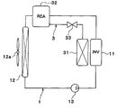
第2実施形態に係る熱輸送システムを示す全体構成図である。
第3実施形態に係る熱輸送システムを示す全体構成図である。
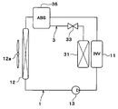
第4実施形態に係る熱輸送システムを示す全体構成図である。
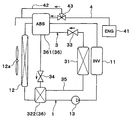
第5実施形態に係る熱輸送システムを示す全体構成図である。
以下に、図面を参照しながら本開示を実施するための複数の形態を説明する。各形態において先行する形態で説明した事項に対応する部分には同一の参照符号を付して重複する説明を省略する場合がある。各形態において構成の一部のみを説明している場合は、構成の他の部分については先行して説明した形態と同様とする。実施の各形態で具体的に説明している部分の組合せばかりではなく、特に組合せに支障が生じなければ、実施の形態同士を部分的に組み合せることも可能である。
(第1実施形態)
第1実施形態について図1および図2に基づいて説明する。本実施形態は、本開示に係る熱輸送システムを、ハイブリッド自動車に搭載したものである。
第1実施形態について図1および図2に基づいて説明する。本実施形態は、本開示に係る熱輸送システムを、ハイブリッド自動車に搭載したものである。
図1に示すように、本実施形態の熱輸送システムは、インバータ11を冷却する冷却システムの冷却水が流通する冷却水回路1と、車両用空調装置を構成する蒸気圧縮式冷凍サイクルの冷媒が流通する冷媒回路2とを備えている。ここで、本実施形態の冷却水が本開示の第1熱媒体に相当しており、本実施形態の冷却水回路が本開示の第1回路に相当している。また、本実施形態の冷媒が本開示の第2熱媒体に相当しており、本実施形態の冷媒回路が本開示の第2回路に相当している。
冷却システムは、インバータ11の冷却水をラジエータ12にて冷却するシステムとなっている。すなわち、本実施形態の冷却システムは、インバータ11からの熱を、冷却水を介してラジエータ12へ輸送するシステムとなっている。
インバータ11は、エネルギ変換により熱を発生するものであり、本開示の第1熱源に相当している。また、ラジエータ12は、インバータ11の排熱と熱交換して高温となった冷却水と、送風ファン12aにより送風された外気と熱交換させて、冷却水の有する熱を系外へ放出する熱交換器である。ラジエータ12は、本開示の第1放熱部に相当している。
インバータ11とラジエータ12は、インバータ11とラジエータ12との間で閉回路を形成する冷却水回路1によって接続されている。冷却水回路1には、冷却水を吸入して吐出する流体機械であるポンプ13が設けられている。ポンプ13は、電動モータによって駆動される電動ポンプであり、冷却水回路1における冷却水の流動を制御する流動制御部である。そして、冷却水回路1内の冷却水は、インバータ11の冷却水出口からラジエータ12を経由してインバータ11の冷却水入口に循環する。
蒸気圧縮式冷凍サイクルは、空調対象空間である車室内へ送風される空気を冷却する機能を果たす。冷凍サイクルの冷媒回路2には、圧縮機21、凝縮部22、膨張弁23、および蒸発部24が設けられている。
圧縮機21は、冷凍サイクルにおいて冷媒を吸入し、圧縮して吐出するものである。本実施形態の圧縮機21は、 吐出容量が固定された固定容量型の圧縮機構を電動モータに
て駆動する電動圧縮機として構成されている。
て駆動する電動圧縮機として構成されている。
凝縮部22は、圧縮機21から吐出した高圧冷媒と、冷却水回路1を流れる冷却水とを熱交換させて、高圧冷媒を凝縮させる熱交換器であり、本開示の第2放熱部に相当している。凝縮部22は、高圧冷媒(気相冷媒)を凝縮させる際に生じる凝縮熱を冷却水に放出する。
本実施形態の凝縮部22では、圧縮機21から吐出した高圧冷媒と、冷却水回路1を流れる冷却水とが直接熱交換する。また、本実施形態の凝縮部22は、冷却水回路1におけるインバータ11の出口側とラジエータ12の入口側との間に配置されている。
膨張弁23は、凝縮部22から流出した液相冷媒を減圧膨張させる減圧部である。蒸発部24は、膨張弁23で減圧膨張された低圧冷媒と車室内へ送風される空気(第3熱媒体)とを熱交換させることによって低圧冷媒を蒸発させる熱交換器である。蒸発部24は、低圧冷媒(液相冷媒)の蒸発により冷熱を生成し、その冷熱を当該空気に放出する。蒸発部24で蒸発した気相冷媒は、圧縮機21に吸入されて圧縮される。
次に、本実施形態に係る冷却システムで用いられる冷却水について説明する。本実施形態の冷却水は、溶媒と少なくとも1種類の溶質60とを有する溶液により構成されている。
図2に示すように、冷却水の溶質60は、第1部位であるヘッド61と、第2部位であるテール62とを備える分子により構成されている。ヘッド61は、冷却水の温度が予め定めた基準温度以下になった場合に、溶媒の固液界面70に選択的に近接する部位である。テール62は疎溶媒性の部位であり、ヘッド61に接続される。
本実施形態では、溶媒として水が採用されている。すなわち、テール62は疎水性を有する。また、溶質60のヘッド61として、第4級アンモニウム基、スルホ基、エステル基、カルボキシル基およびヒドロキル基のうちのいずれかが採用されている。また、溶質60のテール62として、複数の炭素を主鎖とするとともに、各炭素と結合される親水基が4個以下であるものが採用されている。
具体的には、本実施形態の溶質60として、ヘッド61がトリメチルアンモニウム基であるとともに、テール62が炭素数16以下の直鎖状炭化水素基である化合物を採用している。具体的には、溶質60として、臭化ヘキサデシルトリメチルアンモニウム(以下、C16TABともいう)を採用している。
なお、本実施形態の溶質60としては、C16TABの他に、ポリオキシエチレン(10)オクチルフェニルエーテル(Triton(登録商標)X-100)、ポリオキシエチレン(25)オクチルドデシルエーテル(エマルゲン(登録商標)2025G)、オレイン酸ポリオキシエチレンソルビタン(Tween(登録商標)80)、ステアリン酸PEG-150、ミリスチルスルホベタイン、コール酸ナトリウムを採用することができる。
以上説明したように、本実施形態では、凝縮部22において、冷媒が冷却水へ熱を放出する。このため、凝縮部22から冷媒の有する熱を系外へ放出するために、エンジンルーム内において凝縮部22をラジエータ12と直列に配置する必要がなくなる。これにより、エンジンルームにおける放熱用熱交換器の搭載スペースを減少させることができる。
そして、本実施形態では、冷却水の溶質60を、冷却水温度が基準温度以下になった場合に、水の固液界面70に選択的に近接するヘッド61と、ヘッド61に接続されるとともに、疎水性のテール62とを備える分子により構成している。
これによれば、冷却水の温度が低下して基準温度以下になった場合に、溶質60のヘッド61が水の固液界面70に選択的に近接して吸着する。そして、水の固液界面70に吸着したヘッド61により、水の氷核(凝固核)の成長が阻害されるため、凍結の進行を抑制できる。さらに、疎水性のテール62により、水が固液界面70に近づくことが抑制されるので、凍結の進行をより抑制できる。
このため、冷却水に凝固点降下剤(チレングリコール)を含有させなくても、冷却水の凍結の進行を遅らせる、すなわち冷却水の凝固点を低下させることができる。これにより、冷却水の熱物性悪化および粘度増加を抑制しつつ、冷却水の不凍性能を充分に確保することできる。
したがって、冷却水回路1を流通する冷却水として、本実施形態の冷却水を用いることで、冷却水の有する熱を系外へ放熱するラジエータ12の体格を小型化することができる。これにより、エンジンルームにおけるラジエータ12の搭載スペースを確実に減少させることが可能となる。
また、冷却水の粘度増加が抑制されているので、ポンプ13の動力を低減させることができる。
ところで、図2に示すように、本実施形態の冷却水において、溶質60のヘッド61が水の固液界面70に吸着した際に、テール62はヘッド61を基点として運動する。このとき、隣り合う溶質分子のテール62同士が接触しないようになっている。したがって、溶質分子のテール62の長さが長すぎると動径も大きくなり、隣り合う溶質分子同士の距離dが長くなるので、氷核の成長を阻害し難くなる。これにより、冷却水の凍結の進行抑制効果が低下してしまう。
これに対し、上述したように、溶質分子のテール62を、炭素数16以下の直鎖状炭化水素基とすることで、テール62の長さが長くなりすぎることを抑制できる。このため、隣り合う溶質分子同士の距離dを短くすることができるので、氷核の成長を阻害し易くなり、冷却水の凍結の進行を確実に抑制することができる。
(第2実施形態)
次に、第2実施形態について図3に基づいて説明する。本第2実施形態は、上記第1実施形態と比較して、蒸気圧縮式冷凍サイクルに代えて、ケミカルヒートポンプサイクルを用いた点が異なるものである。
次に、第2実施形態について図3に基づいて説明する。本第2実施形態は、上記第1実施形態と比較して、蒸気圧縮式冷凍サイクルに代えて、ケミカルヒートポンプサイクルを用いた点が異なるものである。
図3に示すように、本実施形態の熱輸送システムは、ケミカルヒートポンプサイクルの熱媒流体が流通する熱媒流体回路3を備えている。ここで、本実施形態の熱媒流体が本開示の第2熱媒体に相当しており、本実施形態の熱媒流体回路3が本開示の第2回路に相当している。
ケミカルヒートポンプサイクルの熱媒流体回路3には、蒸発部31、反応部32および第1バルブ33が設けられている。
蒸発部31は、熱媒流体回路3を流れる熱媒流体と車室内へ送風される空気とを熱交換させることによって熱媒流体を蒸発させる熱交換器である。蒸発部31は、熱媒流体の蒸発により冷熱を生成し、その冷熱を当該空気に放出する。
反応部32には、蒸発部31にて蒸発した熱媒流体と化学反応する反応媒体が収容されている。反応部32は、気相熱媒流体および反応媒体を反応させて化合物を生成する際に生じる反応熱により、冷却水回路1を流れる冷却水を加熱する。このため、本実施形態の反応部32が、本開示の第2放熱部に相当している。
本実施形態の反応部32では、気相熱媒流体と冷却水とが直接熱交換する。また、本実施形態の反応部32は、冷却水回路1におけるインバータ11の出口側とラジエータ12の入口側との間に配置されている。
第1バルブ33は、熱媒流体回路3における蒸発部31と反応部32との間に設けられている。第1バルブ33は、熱媒流体回路3の開度を調整する第1開度調整部である。
ここで、熱媒流体としては、複数の分子間にて水素結合が発現する流体を採用することができる。反応媒体としては、アルカリ金属またはアルカリ土類金属と、ハロゲンまたは酸素とを有する固体を採用することができる。本実施形態では、熱媒流体として、冷却水回路1を流通する冷却水と同様の構成の流体を採用するとともに、反応媒体として酸化マグネシウム(MgO)を採用している。
すなわち、本実施形態では熱媒流体を、溶媒と1種類の溶質60とを有する溶液により構成している。そして、熱媒流体の溶質60を、熱媒流体温度が基準温度以下になった場合に、水の固液界面70に選択的に近接するヘッド61と、ヘッド61に接続されるとともに、疎水性のテール62とを備える分子により構成している。このため、本実施形態では、熱媒流体の熱物性悪化および粘度増加を抑制しつつ、不凍性能を充分に確保することができる。
その他の構成は、上記第1実施形態と同様である。したがって、本実施形態の熱輸送システムによれば、第1実施形態と同様の効果を得ることができる。
(第3実施形態)
次に、第3実施形態について図4に基づいて説明する。本第3実施形態は、上記第2実施形態と比較して、ケミカルヒートポンプサイクルの構成が異なるものである。
次に、第3実施形態について図4に基づいて説明する。本第3実施形態は、上記第2実施形態と比較して、ケミカルヒートポンプサイクルの構成が異なるものである。
図4に示すように、本実施形態の反応部32は、反応本体部321および凝縮部322を有して構成されている。
反応本体部321には、反応媒体が収容されている。反応本体部321では、気相熱媒流体および反応媒体が反応して化合物を生成する。また、反応本体部321は、系外にて発生する熱である外部熱によって化合物を気相熱媒流体および反応媒体に分離、すなわち再生させる。
反応本体部321は、冷却水回路1におけるラジエータ12の入口側に接続されている。具体的には、反応本体部321は、冷却水回路1におけるインバータ11の出口側とラジエータ12の入口側との間に配置されている。
凝縮部322は、反応本体部321に接続されている。凝縮部322は、反応本体部321において発生した気相熱媒流体を凝縮させる熱交換器である。凝縮部322は、気相熱媒流体を凝縮させる際に生じる凝縮熱により、冷却水回路1を流れる冷却水を加熱する。本実施形態の凝縮部322では、気相熱媒流体と冷却水とが直接熱交換する。
本実施形態の凝縮部322は、冷却水回路1におけるラジエータ12の出口側に接続されている。具体的には、凝縮部322は、冷却水回路1におけるラジエータの出口側とポンプ13の吸入側との間に配置されている。
熱媒流体回路3における反応本体部321の出口側と凝縮部322の入口側との間には、第2バルブ34が設けられている。第2バルブ34は、熱媒流体回路3の開度を調整する第2開度調整部である。
熱媒流体回路3は、凝縮部322の出口側と蒸発部31の入口側とを接続する接続流路35を有している。これにより、熱媒流体回路3は、環状に構成されている。
ところで、本実施形態では、反応本体部321内の化合物を加熱する外部熱として、エンジン(内燃機関)41の排熱が採用されている。
エンジン41は、第1熱源であるインバータ11が発生させる熱よりも高温の熱を発生させる第2熱源である。エンジン41は、当該高温の熱を高温冷却水に放出する。
本実施形態の熱輸送システムは、エンジン41と反応本体部321とを接続するとともに、高温冷却水が流通する高温冷却水回路4を備えている。ここで、本実施形態の高温冷却水が本開示の第4熱媒体に相当し、本実施形態の高温冷却水回路4が本開示の第3回路に相当している。
反応本体部321は、高温冷却水回路4を流通する高温冷却水との間で熱の授受を行う。また、反応本体部321は、高温冷却水の有する熱によって化合物を気相熱媒流体および反応媒体に分離させる。
高温冷却水回路4には、冷却水を、反応本体部321を迂回するように流すバイパス流路42が設けられている。高温冷却水回路4とバイパス流路42との分岐点には、バイパス流路42に流れる高温冷却水流量を調整するための流路切替弁43が設けられている。
次に、本実施形態に係る熱輸送システムの作動を説明する。
ケミカルヒートポンプサイクルの駆動時、すなわち車室内へ送風される空気を冷却する際には、第1バルブ33を開放するとともに、第2バルブ34を閉塞する。さらに、流路切替弁43を、反応本体部321側を閉じてバイパス流路42側を開くように切り替える。
これにより、図4の実線矢印に示すように、蒸発部31において、熱媒流体と車室内へ送風される空気との間で熱交換が行われ、熱媒流体が蒸発する。このとき、蒸発部31において、熱媒流体の蒸発により生成された冷熱が車室内へ送風される空気に放出され、当該空気が冷却される。
そして、蒸発部31にて蒸発した気相熱媒流体は反応本体部321に流入する。これにより、反応本体部321において、気相熱媒流体および反応媒体が反応して化合物が生成される。このとき、反応本体部321にて発生した反応熱は、冷却水回路1を流通する冷却水に放出され、冷却水が加熱される。反応本体部321にて加熱された冷却水の有する熱は、ラジエータ12を介して外気に放出される。
一方、ケミカルヒートポンプサイクルの停止時、すなわち反応本体部321内の化合物の再生時には、第1バルブ33を閉塞するとともに、第2バルブ34を開放する。さらに、流路切替弁43を、反応本体部321側を開いてバイパス流路42側を閉じるように切り替える。
これにより、図4の破線矢印に示すように、反応本体部321に高温冷却水が流通し、高温冷却水の有する熱により化合物が加熱される。そして、化合物が、気相熱媒流体および反応媒体に分離する。
反応本体部321にて発生した気相熱媒流体は、凝縮部322に流入する。そして、凝縮部322において、凝縮部322に流入した気相熱媒流体と冷却水回路1を流れる冷却水との間で熱交換が行われ、熱媒流体が凝縮する。このとき、凝縮部322にて発生した凝縮熱は、冷却水回路1を流通する冷却水に放出され、冷却水が加熱される。凝縮部322にて加熱された冷却水の有する熱は、ラジエータ12を介して外気に放出される。
そして、凝縮部322にて凝縮した液相熱媒流体は、接続流路35を介して、蒸発部31に流入する。
ここで、本実施形態では、高温冷却水として、冷却水回路1を流通する冷却水と同様の構成の流体を採用している。すなわち、本実施形態では高温冷却水を、溶媒と1種類の溶質60とを有する溶液により構成している。そして、熱媒流体の溶質60を、熱媒流体温度が基準温度以下になった場合に、水の固液界面70に選択的に近接するヘッド61と、ヘッド61に接続されるとともに、疎水性のテール62とを備える分子により構成している。このため、本実施形態では、高温冷却水の熱物性悪化および粘度増加を抑制しつつ、不凍性能を充分に確保することができる。
その他の構成は、上記第2実施形態と同様である。したがって、本実施形態の熱輸送システムによれば、第2実施形態と同様の効果を得ることができる。さらに、反応本体部321において、エンジン1の排熱、すなわち高温冷却水の有する熱により化合物が加熱されることで、化合物の再生を行うことができる。
(第4実施形態)
次に、第4実施形態について図5に基づいて説明する。本第4実施形態は、上記第2実施形態と比較して、ケミカルヒートポンプサイクルに代えて、吸収式ヒートポンプサイクルを用いた点が異なるものである。すなわち、本第4実施形態は、上記第2実施形態の反応部32に代えて、吸収部36を設けたものであり、その他の構成は第2実施形態と同様である。
次に、第4実施形態について図5に基づいて説明する。本第4実施形態は、上記第2実施形態と比較して、ケミカルヒートポンプサイクルに代えて、吸収式ヒートポンプサイクルを用いた点が異なるものである。すなわち、本第4実施形態は、上記第2実施形態の反応部32に代えて、吸収部36を設けたものであり、その他の構成は第2実施形態と同様である。
図5に示すように、本実施形態の熱輸送システムは、吸収式ヒートポンプサイクルの熱媒流体が流通する熱媒流体回路3を備えている。ここで、本実施形態の熱媒流体が本開示の第2熱媒体に相当しており、本実施形態の熱媒流体回路3が本開示の第2回路に相当している。
吸収式ヒートポンプサイクルの熱媒流体回路3には、蒸発部31、吸収部36および第1バルブ33が設けられている。
吸収部36には、蒸発部31にて蒸発した熱媒流体を吸収する吸収媒体が収容されている。吸収部36は、気相熱媒流体を吸収媒体に吸収させる際に生じる吸収熱により、冷却水回路1を流れる冷却水を加熱する。このため、本実施形態の吸収部36が、本開示の第2放熱部に相当している。
本実施形態の吸収部36では、気相熱媒流体と冷却水とが直接熱交換する。また、本実施形態の吸収部36は、冷却水回路1におけるインバータ11の出口側とラジエータ12の入口側との間に配置されている。
本実施形態の第1バルブ33は、熱媒流体回路3における蒸発部31と吸収部36との間に設けられている。第1バルブ33は、熱媒流体回路3の開度を調整する第3開度調整部である。
本実施形態では、熱媒流体として水を採用するとともに、吸収媒体として臭化リチウムを採用している。また、熱媒流体としてアンモニアを採用するとともに、吸収媒体として水を採用してもよい。
なお、熱媒流体として、冷却水回路1を流通する冷却水と同様の構成の流体を用いてもよい。これによれば、熱媒流体の熱物性悪化および粘度増加を抑制しつつ、不凍性能を充分に確保することができる。
その他の構成は、上記第2実施形態と同様である。したがって、本実施形態の熱輸送システムによれば、第2実施形態と同様の効果を得ることができる。
(第5実施形態)
次に、第5実施形態について図6に基づいて説明する。本第5実施形態は、上記第3実施形態と比較して、ケミカルヒートポンプサイクルに代えて、吸収式ヒートポンプサイクルを用いた点が異なるものである。すなわち、本第5実施形態は、上記第3実施形態の反応本体部321に代えて、吸収本体部361を設けたものであり、その他の構成は第3実施形態と同様である。
次に、第5実施形態について図6に基づいて説明する。本第5実施形態は、上記第3実施形態と比較して、ケミカルヒートポンプサイクルに代えて、吸収式ヒートポンプサイクルを用いた点が異なるものである。すなわち、本第5実施形態は、上記第3実施形態の反応本体部321に代えて、吸収本体部361を設けたものであり、その他の構成は第3実施形態と同様である。
図6に示すように、本実施形態の吸収部36は、吸収本体部361および凝縮部322を有して構成されている。
吸収本体部361には、吸収媒体が収容されている。吸収本体部361では、気相熱媒流体が吸収媒体に吸収される。また、吸収本体部361において、系外にて発生する熱である外部熱によって、熱媒流体を吸収した吸収媒体が気相熱媒流体および吸収媒体に分離される。すなわち、吸収媒体が再生する。
吸収本体部361は、冷却水回路1におけるラジエータ12の入口側に接続されている。具体的には、吸収本体部361は、冷却水回路1におけるインバータ11の出口側とラジエータ12の入口側との間に配置されている。
本実施形態の第2バルブ34は、熱媒流体回路3における吸収本体部361の出口側と凝縮部322の入口側との間に設けられている。第2バルブ34は、熱媒流体回路3の開度を調整する第4開度調整部である。
ところで、本実施形態では、吸収本体部361内の熱媒流体を吸収した吸収媒体を加熱する外部熱として、エンジン41の排熱が採用されている。
本実施形態の熱輸送システムは、エンジン41と吸収本体部361とを接続するとともに、高温冷却水が流通する高温冷却水回路4を備えている。吸収本体部361は、高温冷却水回路4を流通する高温冷却水の有する熱によって、熱媒流体を吸収した吸収媒体を気相熱媒流体および反応媒体に分離させる。ここで、本実施形態の高温冷却水が本開示の第4熱媒体に相当し、本実施形態の高温冷却水回路4が本開示の第3回路に相当している。
次に、本実施形態に係る熱輸送システムの作動を説明する。
吸収式ヒートポンプサイクルの駆動時、すなわち車室内へ送風される空気を冷却する際には、第1バルブ33を開放するとともに、第2バルブ34を閉塞する。さらに、流路切替弁43を、吸収本体部361側を閉じてバイパス流路42側を開くように切り替える。
これにより、図6の実線矢印に示すように、蒸発部31において、熱媒流体と車室内へ送風される空気との間で熱交換が行われ、熱媒流体が蒸発する。このとき、蒸発部31において、熱媒流体の蒸発により生成された冷熱が車室内へ送風される空気に放出され、当該空気が冷却される。
そして、蒸発部31にて蒸発した気相熱媒流体は吸収本体部361に流入する。これにより、吸収本体部361において、気相熱媒流体が吸収媒体に吸収される。このとき、吸収本体部361にて発生した吸収熱は、冷却水回路1を流通する冷却水に放出され、冷却水が加熱される。吸収本体部361にて加熱された冷却水の有する熱は、ラジエータ12を介して外気に放出される。
一方、吸収式ヒートポンプサイクルの停止時、すなわち吸収本体部361内の熱媒流体を吸収した吸収媒体の再生時には、第1バルブ33を閉塞するとともに、第2バルブ34を開放する。さらに、流路切替弁43を、吸収本体部361側を開いてバイパス流路42側を閉じるように切り替える。
これにより、図6の破線矢印に示すように、吸収本体部361に高温冷却水が流通し、高温冷却水の有する熱により、熱媒流体を吸収した吸収媒体が加熱される。そして、熱媒流体を吸収した吸収媒体が、気相熱媒流体および吸収媒体に分離する。
吸収本体部361にて発生した気相熱媒流体は、凝縮部322に流入する。そして、凝縮部322において、凝縮部322に流入した気相熱媒流体と冷却水回路1を流れる冷却水との間で熱交換が行われ、熱媒流体が凝縮する。このとき、凝縮部322にて発生した凝縮熱は、冷却水回路1を流通する冷却水に放出され、冷却水が加熱される。凝縮部322にて加熱された冷却水の有する熱は、ラジエータ12を介して外気に放出される。
そして、凝縮部322にて凝縮した液相熱媒流体は、接続流路35を介して、蒸発部31に流入する。
その他の構成は、上記第3実施形態と同様である。したがって、本実施形態の熱輸送システムによれば、第3実施形態と同様の効果を得ることができる。
(他の実施形態)
本開示は上述の実施形態に限定されることなく、本開示の趣旨を逸脱しない範囲内で、例えば以下のように種々変形可能である。また、上記各実施形態に開示された特徴は、実施可能な範囲で適宜組み合わせてもよい。
本開示は上述の実施形態に限定されることなく、本開示の趣旨を逸脱しない範囲内で、例えば以下のように種々変形可能である。また、上記各実施形態に開示された特徴は、実施可能な範囲で適宜組み合わせてもよい。
(1)上記第1実施形態では、凝縮部22を、高圧冷媒と冷却水とが直接熱交換するように構成した例について説明した。しかしながら、例えば、凝縮部22を、高圧冷媒と冷却水とが他の熱媒体を介して熱交換するように構成してもよい。
同様に、上記第2実施形態において、反応部32を、気相熱媒流体と冷却水とが他の熱媒体を介して熱交換するように構成してもよい。また、上記第3、第5実施形態において、凝縮部322を、気相熱媒流体と冷却水とが他の熱媒体を介して熱交換するように構成してもよい。また、上記第4実施形態において、吸収部36を、気相熱媒流体と冷却水とが他の熱媒体を介して熱交換するように構成してもよい。
(2)上記実施形態では、第1熱源としてインバータ11を採用した例について説明したが、第1熱源はこれに限定されない。例えば、第1熱源として、燃料電池、バッテリ等を採用してもよい。
Claims (14)
- 液体状の第1熱媒体が循環する第1回路(1)と、第2熱媒体が循環する第2回路(2、3)とを備え、
前記第1回路(1)は、熱を発生させる第1熱源(11)と、熱を系外へ放出する第1放熱部(12)とを有しており、
前記第2回路(2、3)は、液体状の前記第2熱媒体の蒸発により冷熱を生成する蒸発部(24、31)と、前記蒸発部(24、31)にて蒸発した気体状の前記第2熱媒体から熱を放出する第2放熱部(22、32、36)とを有している熱輸送システムであって、
前記第2放熱部(22、32、36)では、前記第2熱媒体から前記第1熱媒体へ放出された熱によって、前記第1熱媒体を加熱し、
前記第1回路(1)では、前記第2放熱部(22、32、36)において加熱された前記第1熱媒体の有する熱が前記第1放熱部(12)から系外へ放出され、
前記第1熱媒体は、溶媒と少なくとも1種類の溶質(60)とを有する溶液により構成されており、
前記少なくとも1種類の溶質(60)は、
前記熱媒体の温度が予め定めた基準温度以下になった場合に、前記溶媒の固液界面(70)に選択的に近接する第1部位(61)と、
前記第1部位(61)に接続されるとともに、前記溶媒に対して疎溶媒性である第2部位(62)とを備える分子により構成されている熱輸送システム。 - 前記第2放熱部は、前記気体状の熱媒体を凝縮させる際に生じる凝縮熱を前記第1熱媒体に放出する凝縮部(22)である請求項1に記載の熱輸送システム。
- 前記第2放熱部は、前記気体状の熱媒体を化学反応させる際に生じる反応熱を前記第1熱媒体に放出する反応部(32)である請求項1に記載の熱輸送システム。
- 前記第2放熱部は、前記気体状の熱媒体を吸収させる際に生じる吸収熱を前記第1熱媒体に放出する吸収部(36)である請求項1に記載の熱輸送システム。
- 前記第2回路(2)における前記蒸発部(24)の出口側と前記凝縮部(22)の入口側との間には、前記第2熱媒体を圧縮して吐出する圧縮機(21)が設けられており、
前記第2回路(2)における前記凝縮部(22)の出口側と前記蒸発部(24)の入口側との間には、前記凝縮部(22)から流出した前記第2熱媒体を減圧させる減圧部(23)が設けられており、
前記凝縮部(22)は、前記圧縮機(21)から吐出された高圧の前記第2熱媒体と前記第1熱媒体とを熱交換させて前記高圧の第2冷媒を凝縮させ、
前記蒸発部(24)は、前記減圧部(23)にて減圧された低圧の前記第2熱媒体と第3熱媒体とを熱交換させて前記低圧の第2熱媒体を蒸発させる請求項2に記載の熱輸送システム。 - 前記反応部(32)は、前記第2熱媒体および反応媒体を反応させて化合物を生成する際に生じる反応熱により前記第1熱媒体を加熱し、
前記第2回路(3)における前記蒸発部(31)と前記反応部(32)との間には、前記第2回路(3)の開度を調整する第1開度調整部(33)が設けられている請求項3に記載の熱輸送システム。 - 前記反応部(32)は、
系外にて発生する熱である外部熱によって前記化合物を気体状の前記第2熱媒体および前記反応媒体に分離させる反応本体部(321)と、
前記反応本体部(321)において発生した気体状の前記第2熱媒体を凝縮させる凝縮部(322)とを有しており、
前記凝縮部(322)は、前記気体状の第2熱媒体を凝縮させる際に生じる凝縮熱により前記第1熱媒体を加熱し、
前記反応本体部(321)は、前記第1回路(1)における前記第1放熱部(12)の入口側に接続されており、
前記凝縮部(322)は、前記第1回路(1)における前記第1放熱部(12)の出口側に接続されており、
前記第2回路(3)における前記反応本体部(321)の出口側と前記凝縮部(322)の入口側との間には、前記第2回路(3)の開度を調整する第2開度調整部(34)が設けられており、
前記第2回路(3)は、前記凝縮部(322)の出口側と前記蒸発部(31)の入口側とを接続する接続流路(35)を有している請求項6に記載の熱輸送システム。 - 前記第1熱源(11)が発生させる熱よりも高温の熱を第4熱媒体に放出する第2熱源(41)と前記反応本体部(321)とを接続するとともに、前記第3熱媒体が流通する第3回路(4)をさらに備え、
前記反応本体部(321)は、前記第3回路(4)を流通する前記第4熱媒体との間で熱の授受を行い、
前記反応本体部(321)は、前記第4熱媒体の有する熱によって前記化合物を気体状の前記第2熱媒体および前記反応媒体に分離させる請求項7に記載の熱輸送システム。 - 前記第2熱媒体は、複数の分子間にて水素結合が発現する流体であり、
前記反応媒体は、アルカリ金属またはアルカリ土類金属と、ハロゲンまたは酸素とを有する固体である請求項6ないし8のいずれか1つに記載の熱輸送システム。 - 前記第2熱媒体は、溶媒と少なくとも1種類の溶質(60)とを有する溶液により構成されており、
前記少なくとも1種類の溶質(60)は、
前記熱媒体の温度が予め定めた基準温度以下になった場合に、前記溶媒の固液界面(70)に選択的に近接する第1部位(61)と、
前記第1部位(61)に接続されるとともに、前記溶媒に対して疎溶媒性である第2部位(62)とを備える分子により構成されている請求項9に記載の熱輸送システム。 - 前記吸収部(36)は、前記第2熱媒体を吸収媒体に吸収させる際に生じる吸収熱により前記第1熱媒体を加熱し、
前記第2回路(3)における前記蒸発部(31)と前記吸収部(36)との間には、前記第2回路(3)の開度を調整する第3開度調整部(33)が設けられている請求項4に記載の熱輸送システム。 - 前記吸収部(36)は、
系外にて発生する熱である外部熱によって、前記第2熱媒体を吸収した吸収媒体を、気体状の前記第2熱媒体および前記吸収媒体に分離させる吸収本体部(361)と、
前記吸収本体部(361)において発生した気体状の前記第2熱媒体を凝縮させる凝縮部(322)とを有しており、
前記凝縮部(322)は、前記気体状の第2熱媒体を凝縮させる際に生じる凝縮熱により前記第1熱媒体を加熱し、
前記吸収本体部(361)は、前記第1回路(1)における前記第1放熱部(12)の入口側に接続されており、
前記凝縮部(322)は、前記第1回路(1)における前記第1放熱部(12)の出口側に接続されており、
前記第2回路(3)における前記吸収本体部(361)の出口側と前記凝縮部(322)の入口側との間には、前記第2回路(3)の開度を調整する第4開度調整部(34)が設けられており、
前記第2回路(3)は、前記凝縮部(322)の出口側と前記蒸発部(31)の入口側とを接続する接続流路(35)を有している請求項11に記載の熱輸送システム。 - 前記第1熱源(11)が発生させる熱よりも高温の熱を第4熱媒体に放出する第2熱源(41)と前記吸収本体部(361)とを接続するとともに、前記第4熱媒体が流通する第3回路(4)をさらに備え、
前記吸収本体部(361)は、前記第3回路(4)を流通する前記第4熱媒体との間で熱の授受を行い、
前記吸収本体部(361)は、前記第2熱媒体を吸収した吸収媒体を、前記第4熱媒体の有する熱によって、気体状の前記第2熱媒体および前記反応媒体に分離させる請求項12に記載の熱輸送システム。 - 前記第4熱媒体は、溶媒と少なくとも1種類の溶質(60)とを有する溶液により構成されており、
前記少なくとも1種類の溶質(60)は、
前記熱媒体の温度が予め定めた基準温度以下になった場合に、前記溶媒の固液界面(70)に選択的に近接する第1部位(61)と、
前記第1部位(61)に接続されるとともに、前記溶媒に対して疎溶媒性である第2部位(62)とを備える分子により構成されている請求項8または13に記載の熱輸送システム。
Applications Claiming Priority (2)
| Application Number | Priority Date | Filing Date | Title |
|---|---|---|---|
| JP2014-193337 | 2014-09-24 | ||
| JP2014193337A JP6432243B2 (ja) | 2014-09-24 | 2014-09-24 | 熱輸送システム |
Publications (1)
| Publication Number | Publication Date |
|---|---|
| WO2016047017A1 true WO2016047017A1 (ja) | 2016-03-31 |
Family
ID=55580573
Family Applications (1)
| Application Number | Title | Priority Date | Filing Date |
|---|---|---|---|
| PCT/JP2015/003901 Ceased WO2016047017A1 (ja) | 2014-09-24 | 2015-08-03 | 熱輸送システム |
Country Status (2)
| Country | Link |
|---|---|
| JP (1) | JP6432243B2 (ja) |
| WO (1) | WO2016047017A1 (ja) |
Citations (11)
| Publication number | Priority date | Publication date | Assignee | Title |
|---|---|---|---|---|
| JPH03225162A (ja) * | 1990-01-31 | 1991-10-04 | Yazaki Corp | ケミカルヒートポンプ |
| JPH09194817A (ja) * | 1996-01-11 | 1997-07-29 | Hitachi Ltd | 熱媒体と熱媒体循環システム |
| JPH10246529A (ja) * | 1997-03-03 | 1998-09-14 | Rinnai Corp | 吸収式冷却装置 |
| JP2005306300A (ja) * | 2004-04-23 | 2005-11-04 | Denso Corp | 車両用空調装置 |
| JP2010127282A (ja) * | 2008-11-26 | 2010-06-10 | Scania Cv Ab (Publ) | 車両の冷却システム内の冷却液の追加冷却のための方法及びシステム |
| JP2010133291A (ja) * | 2008-12-03 | 2010-06-17 | Nissan Motor Co Ltd | 内燃機関の冷却装置 |
| JP2011163730A (ja) * | 2010-02-15 | 2011-08-25 | Chiba Univ | ケミカルヒートポンプ及びそれを用いたハイブリッド冷凍システム |
| JP2012091547A (ja) * | 2010-10-25 | 2012-05-17 | Toyota Industries Corp | ハイブリッド車両用冷房装置 |
| JP2012214104A (ja) * | 2011-03-31 | 2012-11-08 | Toyota Industries Corp | ハイブリッド車両用冷却装置 |
| JP2013032456A (ja) * | 2011-08-03 | 2013-02-14 | Hokkaido Univ | 過冷却促進剤 |
| JP2013139959A (ja) * | 2012-01-04 | 2013-07-18 | Chugai Ro Co Ltd | 熱利用方法およびこれを利用した加熱設備 |
-
2014
- 2014-09-24 JP JP2014193337A patent/JP6432243B2/ja not_active Expired - Fee Related
-
2015
- 2015-08-03 WO PCT/JP2015/003901 patent/WO2016047017A1/ja not_active Ceased
Patent Citations (11)
| Publication number | Priority date | Publication date | Assignee | Title |
|---|---|---|---|---|
| JPH03225162A (ja) * | 1990-01-31 | 1991-10-04 | Yazaki Corp | ケミカルヒートポンプ |
| JPH09194817A (ja) * | 1996-01-11 | 1997-07-29 | Hitachi Ltd | 熱媒体と熱媒体循環システム |
| JPH10246529A (ja) * | 1997-03-03 | 1998-09-14 | Rinnai Corp | 吸収式冷却装置 |
| JP2005306300A (ja) * | 2004-04-23 | 2005-11-04 | Denso Corp | 車両用空調装置 |
| JP2010127282A (ja) * | 2008-11-26 | 2010-06-10 | Scania Cv Ab (Publ) | 車両の冷却システム内の冷却液の追加冷却のための方法及びシステム |
| JP2010133291A (ja) * | 2008-12-03 | 2010-06-17 | Nissan Motor Co Ltd | 内燃機関の冷却装置 |
| JP2011163730A (ja) * | 2010-02-15 | 2011-08-25 | Chiba Univ | ケミカルヒートポンプ及びそれを用いたハイブリッド冷凍システム |
| JP2012091547A (ja) * | 2010-10-25 | 2012-05-17 | Toyota Industries Corp | ハイブリッド車両用冷房装置 |
| JP2012214104A (ja) * | 2011-03-31 | 2012-11-08 | Toyota Industries Corp | ハイブリッド車両用冷却装置 |
| JP2013032456A (ja) * | 2011-08-03 | 2013-02-14 | Hokkaido Univ | 過冷却促進剤 |
| JP2013139959A (ja) * | 2012-01-04 | 2013-07-18 | Chugai Ro Co Ltd | 熱利用方法およびこれを利用した加熱設備 |
Also Published As
| Publication number | Publication date |
|---|---|
| JP6432243B2 (ja) | 2018-12-05 |
| JP2016065654A (ja) | 2016-04-28 |
Similar Documents
| Publication | Publication Date | Title |
|---|---|---|
| JP5755490B2 (ja) | 冷却装置 | |
| EP3025887B1 (en) | Vehicle air conditioner | |
| CN109477696B (zh) | 设备温度调节装置 | |
| CN102555732B (zh) | 汽车的冷却设备 | |
| JP6083304B2 (ja) | 車両用熱管理システム | |
| WO2015136768A1 (ja) | 車載温調装置、車両用空調装置及びバッテリ温調装置 | |
| JP2003097857A (ja) | 冷房サイクル | |
| EP2781381B1 (en) | Device for cooling electrical apparatus | |
| WO2015133083A1 (ja) | 車両用熱管理システム | |
| CN103380339A (zh) | 单体热泵式空气调节器 | |
| WO2014073150A1 (ja) | 冷却装置 | |
| CN114174736A (zh) | 热管理装置 | |
| KR101952115B1 (ko) | 자동차 객실 공기 조화 및 드라이브 부품 냉각 시스템 그리고 상기 시스템의 작동 방법 | |
| JP2011152808A (ja) | 車両の空調装置 | |
| JP2012091547A (ja) | ハイブリッド車両用冷房装置 | |
| WO2020162545A1 (ja) | 熱輸送媒体および熱輸送システム | |
| JP2010126026A (ja) | 車両用空調装置 | |
| JP6432243B2 (ja) | 熱輸送システム | |
| JP2025018231A (ja) | アキュムレータ及び車両駆動装置 | |
| JP2005297684A (ja) | 蒸発圧縮式冷凍機 | |
| JP2004278948A (ja) | カーエアコン用熱交換器 | |
| JP2008273220A (ja) | 車両用冷房装置 | |
| CN119159957B (zh) | 基于十二通阀的热管理系统 | |
| CN120056697B (zh) | 一种基于r290制冷剂的汽车热管理系统 | |
| JP2012140060A (ja) | 冷却装置 |
Legal Events
| Date | Code | Title | Description |
|---|---|---|---|
| 121 | Ep: the epo has been informed by wipo that ep was designated in this application |
Ref document number: 15845410 Country of ref document: EP Kind code of ref document: A1 |
|
| NENP | Non-entry into the national phase |
Ref country code: DE |
|
| 122 | Ep: pct application non-entry in european phase |
Ref document number: 15845410 Country of ref document: EP Kind code of ref document: A1 |