WO2016042708A1 - Packaging box and object packaged in said packaging box - Google Patents
Packaging box and object packaged in said packaging box Download PDFInfo
- Publication number
- WO2016042708A1 WO2016042708A1 PCT/JP2015/004240 JP2015004240W WO2016042708A1 WO 2016042708 A1 WO2016042708 A1 WO 2016042708A1 JP 2015004240 W JP2015004240 W JP 2015004240W WO 2016042708 A1 WO2016042708 A1 WO 2016042708A1
- Authority
- WO
- WIPO (PCT)
- Prior art keywords
- box body
- lid
- opening
- packaging box
- folded
- Prior art date
Links
Images


Classifications
-
- B—PERFORMING OPERATIONS; TRANSPORTING
- B65—CONVEYING; PACKING; STORING; HANDLING THIN OR FILAMENTARY MATERIAL
- B65D—CONTAINERS FOR STORAGE OR TRANSPORT OF ARTICLES OR MATERIALS, e.g. BAGS, BARRELS, BOTTLES, BOXES, CANS, CARTONS, CRATES, DRUMS, JARS, TANKS, HOPPERS, FORWARDING CONTAINERS; ACCESSORIES, CLOSURES, OR FITTINGS THEREFOR; PACKAGING ELEMENTS; PACKAGES
- B65D5/00—Rigid or semi-rigid containers of polygonal cross-section, e.g. boxes, cartons or trays, formed by folding or erecting one or more blanks made of paper
- B65D5/02—Rigid or semi-rigid containers of polygonal cross-section, e.g. boxes, cartons or trays, formed by folding or erecting one or more blanks made of paper by folding or erecting a single blank to form a tubular body with or without subsequent folding operations, or the addition of separate elements, to close the ends of the body
- B65D5/0254—Rigid or semi-rigid containers of polygonal cross-section, e.g. boxes, cartons or trays, formed by folding or erecting one or more blanks made of paper by folding or erecting a single blank to form a tubular body with or without subsequent folding operations, or the addition of separate elements, to close the ends of the body with end closures formed by inward folding of flaps and securing them by means of a tongue integral with one of the flaps
-
- B—PERFORMING OPERATIONS; TRANSPORTING
- B65—CONVEYING; PACKING; STORING; HANDLING THIN OR FILAMENTARY MATERIAL
- B65D—CONTAINERS FOR STORAGE OR TRANSPORT OF ARTICLES OR MATERIALS, e.g. BAGS, BARRELS, BOTTLES, BOXES, CANS, CARTONS, CRATES, DRUMS, JARS, TANKS, HOPPERS, FORWARDING CONTAINERS; ACCESSORIES, CLOSURES, OR FITTINGS THEREFOR; PACKAGING ELEMENTS; PACKAGES
- B65D43/00—Lids or covers for rigid or semi-rigid containers
- B65D43/02—Removable lids or covers
- B65D43/0202—Removable lids or covers without integral tamper element
-
- B—PERFORMING OPERATIONS; TRANSPORTING
- B65—CONVEYING; PACKING; STORING; HANDLING THIN OR FILAMENTARY MATERIAL
- B65D—CONTAINERS FOR STORAGE OR TRANSPORT OF ARTICLES OR MATERIALS, e.g. BAGS, BARRELS, BOTTLES, BOXES, CANS, CARTONS, CRATES, DRUMS, JARS, TANKS, HOPPERS, FORWARDING CONTAINERS; ACCESSORIES, CLOSURES, OR FITTINGS THEREFOR; PACKAGING ELEMENTS; PACKAGES
- B65D11/00—Containers having bodies formed by interconnecting or uniting two or more rigid, or substantially rigid, components made wholly or mainly of plastics material
- B65D11/10—Containers having bodies formed by interconnecting or uniting two or more rigid, or substantially rigid, components made wholly or mainly of plastics material of polygonal cross-section and all parts being permanently connected to each other
-
- B—PERFORMING OPERATIONS; TRANSPORTING
- B65—CONVEYING; PACKING; STORING; HANDLING THIN OR FILAMENTARY MATERIAL
- B65D—CONTAINERS FOR STORAGE OR TRANSPORT OF ARTICLES OR MATERIALS, e.g. BAGS, BARRELS, BOTTLES, BOXES, CANS, CARTONS, CRATES, DRUMS, JARS, TANKS, HOPPERS, FORWARDING CONTAINERS; ACCESSORIES, CLOSURES, OR FITTINGS THEREFOR; PACKAGING ELEMENTS; PACKAGES
- B65D15/00—Containers having bodies formed by interconnecting or uniting two or more rigid, or substantially rigid, sections made of different materials
- B65D15/22—Containers having bodies formed by interconnecting or uniting two or more rigid, or substantially rigid, sections made of different materials of polygonal cross-section
-
- B—PERFORMING OPERATIONS; TRANSPORTING
- B65—CONVEYING; PACKING; STORING; HANDLING THIN OR FILAMENTARY MATERIAL
- B65D—CONTAINERS FOR STORAGE OR TRANSPORT OF ARTICLES OR MATERIALS, e.g. BAGS, BARRELS, BOTTLES, BOXES, CANS, CARTONS, CRATES, DRUMS, JARS, TANKS, HOPPERS, FORWARDING CONTAINERS; ACCESSORIES, CLOSURES, OR FITTINGS THEREFOR; PACKAGING ELEMENTS; PACKAGES
- B65D5/00—Rigid or semi-rigid containers of polygonal cross-section, e.g. boxes, cartons or trays, formed by folding or erecting one or more blanks made of paper
- B65D5/02—Rigid or semi-rigid containers of polygonal cross-section, e.g. boxes, cartons or trays, formed by folding or erecting one or more blanks made of paper by folding or erecting a single blank to form a tubular body with or without subsequent folding operations, or the addition of separate elements, to close the ends of the body
- B65D5/12—Rigid or semi-rigid containers of polygonal cross-section, e.g. boxes, cartons or trays, formed by folding or erecting one or more blanks made of paper by folding or erecting a single blank to form a tubular body with or without subsequent folding operations, or the addition of separate elements, to close the ends of the body with end closures formed separately from tubular body
- B65D5/14—Rigid or semi-rigid containers of polygonal cross-section, e.g. boxes, cartons or trays, formed by folding or erecting one or more blanks made of paper by folding or erecting a single blank to form a tubular body with or without subsequent folding operations, or the addition of separate elements, to close the ends of the body with end closures formed separately from tubular body with inset end closures
-
- B—PERFORMING OPERATIONS; TRANSPORTING
- B65—CONVEYING; PACKING; STORING; HANDLING THIN OR FILAMENTARY MATERIAL
- B65D—CONTAINERS FOR STORAGE OR TRANSPORT OF ARTICLES OR MATERIALS, e.g. BAGS, BARRELS, BOTTLES, BOXES, CANS, CARTONS, CRATES, DRUMS, JARS, TANKS, HOPPERS, FORWARDING CONTAINERS; ACCESSORIES, CLOSURES, OR FITTINGS THEREFOR; PACKAGING ELEMENTS; PACKAGES
- B65D51/00—Closures not otherwise provided for
- B65D51/24—Closures not otherwise provided for combined or co-operating with auxiliary devices for non-closing purposes
- B65D51/242—Closures not otherwise provided for combined or co-operating with auxiliary devices for non-closing purposes provided with means for facilitating lifting or suspending of the container
-
- B—PERFORMING OPERATIONS; TRANSPORTING
- B65—CONVEYING; PACKING; STORING; HANDLING THIN OR FILAMENTARY MATERIAL
- B65D—CONTAINERS FOR STORAGE OR TRANSPORT OF ARTICLES OR MATERIALS, e.g. BAGS, BARRELS, BOTTLES, BOXES, CANS, CARTONS, CRATES, DRUMS, JARS, TANKS, HOPPERS, FORWARDING CONTAINERS; ACCESSORIES, CLOSURES, OR FITTINGS THEREFOR; PACKAGING ELEMENTS; PACKAGES
- B65D77/00—Packages formed by enclosing articles or materials in preformed containers, e.g. boxes, cartons, sacks or bags
- B65D77/22—Details
- B65D77/30—Opening or contents-removing devices added or incorporated during filling or closing of containers
-
- B—PERFORMING OPERATIONS; TRANSPORTING
- B65—CONVEYING; PACKING; STORING; HANDLING THIN OR FILAMENTARY MATERIAL
- B65D—CONTAINERS FOR STORAGE OR TRANSPORT OF ARTICLES OR MATERIALS, e.g. BAGS, BARRELS, BOTTLES, BOXES, CANS, CARTONS, CRATES, DRUMS, JARS, TANKS, HOPPERS, FORWARDING CONTAINERS; ACCESSORIES, CLOSURES, OR FITTINGS THEREFOR; PACKAGING ELEMENTS; PACKAGES
- B65D83/00—Containers or packages with special means for dispensing contents
- B65D83/0005—Containers or packages provided with a piston or with a movable bottom or partition having approximately the same section as the container
-
- B—PERFORMING OPERATIONS; TRANSPORTING
- B65—CONVEYING; PACKING; STORING; HANDLING THIN OR FILAMENTARY MATERIAL
- B65D—CONTAINERS FOR STORAGE OR TRANSPORT OF ARTICLES OR MATERIALS, e.g. BAGS, BARRELS, BOTTLES, BOXES, CANS, CARTONS, CRATES, DRUMS, JARS, TANKS, HOPPERS, FORWARDING CONTAINERS; ACCESSORIES, CLOSURES, OR FITTINGS THEREFOR; PACKAGING ELEMENTS; PACKAGES
- B65D11/00—Containers having bodies formed by interconnecting or uniting two or more rigid, or substantially rigid, components made wholly or mainly of plastics material
- B65D11/02—Containers having bodies formed by interconnecting or uniting two or more rigid, or substantially rigid, components made wholly or mainly of plastics material of curved cross-section
-
- B—PERFORMING OPERATIONS; TRANSPORTING
- B65—CONVEYING; PACKING; STORING; HANDLING THIN OR FILAMENTARY MATERIAL
- B65D—CONTAINERS FOR STORAGE OR TRANSPORT OF ARTICLES OR MATERIALS, e.g. BAGS, BARRELS, BOTTLES, BOXES, CANS, CARTONS, CRATES, DRUMS, JARS, TANKS, HOPPERS, FORWARDING CONTAINERS; ACCESSORIES, CLOSURES, OR FITTINGS THEREFOR; PACKAGING ELEMENTS; PACKAGES
- B65D15/00—Containers having bodies formed by interconnecting or uniting two or more rigid, or substantially rigid, sections made of different materials
- B65D15/02—Containers having bodies formed by interconnecting or uniting two or more rigid, or substantially rigid, sections made of different materials of curved, or partially curved, cross-section, e.g. cans, drums
- B65D15/16—Containers having bodies formed by interconnecting or uniting two or more rigid, or substantially rigid, sections made of different materials of curved, or partially curved, cross-section, e.g. cans, drums with curved, or partially curved, walls made of plastics material
- B65D15/20—Containers having bodies formed by interconnecting or uniting two or more rigid, or substantially rigid, sections made of different materials of curved, or partially curved, cross-section, e.g. cans, drums with curved, or partially curved, walls made of plastics material with end walls made of paper
-
- B—PERFORMING OPERATIONS; TRANSPORTING
- B65—CONVEYING; PACKING; STORING; HANDLING THIN OR FILAMENTARY MATERIAL
- B65D—CONTAINERS FOR STORAGE OR TRANSPORT OF ARTICLES OR MATERIALS, e.g. BAGS, BARRELS, BOTTLES, BOXES, CANS, CARTONS, CRATES, DRUMS, JARS, TANKS, HOPPERS, FORWARDING CONTAINERS; ACCESSORIES, CLOSURES, OR FITTINGS THEREFOR; PACKAGING ELEMENTS; PACKAGES
- B65D2543/00—Lids or covers essentially for box-like containers
- B65D2543/00009—Details of lids or covers for rigid or semi-rigid containers
- B65D2543/00018—Overall construction of the lid
- B65D2543/00259—Materials used
- B65D2543/00268—Paper
-
- B—PERFORMING OPERATIONS; TRANSPORTING
- B65—CONVEYING; PACKING; STORING; HANDLING THIN OR FILAMENTARY MATERIAL
- B65D—CONTAINERS FOR STORAGE OR TRANSPORT OF ARTICLES OR MATERIALS, e.g. BAGS, BARRELS, BOTTLES, BOXES, CANS, CARTONS, CRATES, DRUMS, JARS, TANKS, HOPPERS, FORWARDING CONTAINERS; ACCESSORIES, CLOSURES, OR FITTINGS THEREFOR; PACKAGING ELEMENTS; PACKAGES
- B65D2543/00—Lids or covers essentially for box-like containers
- B65D2543/00009—Details of lids or covers for rigid or semi-rigid containers
- B65D2543/00018—Overall construction of the lid
- B65D2543/00259—Materials used
- B65D2543/00296—Plastic
-
- B—PERFORMING OPERATIONS; TRANSPORTING
- B65—CONVEYING; PACKING; STORING; HANDLING THIN OR FILAMENTARY MATERIAL
- B65D—CONTAINERS FOR STORAGE OR TRANSPORT OF ARTICLES OR MATERIALS, e.g. BAGS, BARRELS, BOTTLES, BOXES, CANS, CARTONS, CRATES, DRUMS, JARS, TANKS, HOPPERS, FORWARDING CONTAINERS; ACCESSORIES, CLOSURES, OR FITTINGS THEREFOR; PACKAGING ELEMENTS; PACKAGES
- B65D2543/00—Lids or covers essentially for box-like containers
- B65D2543/00009—Details of lids or covers for rigid or semi-rigid containers
- B65D2543/00444—Contact between the container and the lid
- B65D2543/00481—Contact between the container and the lid on the inside or the outside of the container
- B65D2543/0049—Contact between the container and the lid on the inside or the outside of the container on the inside, or a part turned to the inside of the mouth of the container
- B65D2543/00518—Skirt
-
- B—PERFORMING OPERATIONS; TRANSPORTING
- B65—CONVEYING; PACKING; STORING; HANDLING THIN OR FILAMENTARY MATERIAL
- B65D—CONTAINERS FOR STORAGE OR TRANSPORT OF ARTICLES OR MATERIALS, e.g. BAGS, BARRELS, BOTTLES, BOXES, CANS, CARTONS, CRATES, DRUMS, JARS, TANKS, HOPPERS, FORWARDING CONTAINERS; ACCESSORIES, CLOSURES, OR FITTINGS THEREFOR; PACKAGING ELEMENTS; PACKAGES
- B65D2543/00—Lids or covers essentially for box-like containers
- B65D2543/00009—Details of lids or covers for rigid or semi-rigid containers
- B65D2543/00824—Means for facilitating removing of the closure
- B65D2543/00833—Integral tabs, tongues, handles or similar
- B65D2543/00851—Integral tabs, tongues, handles or similar on the central part of the lid
-
- B—PERFORMING OPERATIONS; TRANSPORTING
- B65—CONVEYING; PACKING; STORING; HANDLING THIN OR FILAMENTARY MATERIAL
- B65D—CONTAINERS FOR STORAGE OR TRANSPORT OF ARTICLES OR MATERIALS, e.g. BAGS, BARRELS, BOTTLES, BOXES, CANS, CARTONS, CRATES, DRUMS, JARS, TANKS, HOPPERS, FORWARDING CONTAINERS; ACCESSORIES, CLOSURES, OR FITTINGS THEREFOR; PACKAGING ELEMENTS; PACKAGES
- B65D5/00—Rigid or semi-rigid containers of polygonal cross-section, e.g. boxes, cartons or trays, formed by folding or erecting one or more blanks made of paper
- B65D5/02—Rigid or semi-rigid containers of polygonal cross-section, e.g. boxes, cartons or trays, formed by folding or erecting one or more blanks made of paper by folding or erecting a single blank to form a tubular body with or without subsequent folding operations, or the addition of separate elements, to close the ends of the body
- B65D5/0209—Rigid or semi-rigid containers of polygonal cross-section, e.g. boxes, cartons or trays, formed by folding or erecting one or more blanks made of paper by folding or erecting a single blank to form a tubular body with or without subsequent folding operations, or the addition of separate elements, to close the ends of the body the tubular body having a curved or partially curved cross-section
-
- B—PERFORMING OPERATIONS; TRANSPORTING
- B65—CONVEYING; PACKING; STORING; HANDLING THIN OR FILAMENTARY MATERIAL
- B65D—CONTAINERS FOR STORAGE OR TRANSPORT OF ARTICLES OR MATERIALS, e.g. BAGS, BARRELS, BOTTLES, BOXES, CANS, CARTONS, CRATES, DRUMS, JARS, TANKS, HOPPERS, FORWARDING CONTAINERS; ACCESSORIES, CLOSURES, OR FITTINGS THEREFOR; PACKAGING ELEMENTS; PACKAGES
- B65D5/00—Rigid or semi-rigid containers of polygonal cross-section, e.g. boxes, cartons or trays, formed by folding or erecting one or more blanks made of paper
- B65D5/02—Rigid or semi-rigid containers of polygonal cross-section, e.g. boxes, cartons or trays, formed by folding or erecting one or more blanks made of paper by folding or erecting a single blank to form a tubular body with or without subsequent folding operations, or the addition of separate elements, to close the ends of the body
- B65D5/029—Rigid or semi-rigid containers of polygonal cross-section, e.g. boxes, cartons or trays, formed by folding or erecting one or more blanks made of paper by folding or erecting a single blank to form a tubular body with or without subsequent folding operations, or the addition of separate elements, to close the ends of the body the tubular body presenting a special shape
-
- B—PERFORMING OPERATIONS; TRANSPORTING
- B65—CONVEYING; PACKING; STORING; HANDLING THIN OR FILAMENTARY MATERIAL
- B65D—CONTAINERS FOR STORAGE OR TRANSPORT OF ARTICLES OR MATERIALS, e.g. BAGS, BARRELS, BOTTLES, BOXES, CANS, CARTONS, CRATES, DRUMS, JARS, TANKS, HOPPERS, FORWARDING CONTAINERS; ACCESSORIES, CLOSURES, OR FITTINGS THEREFOR; PACKAGING ELEMENTS; PACKAGES
- B65D5/00—Rigid or semi-rigid containers of polygonal cross-section, e.g. boxes, cartons or trays, formed by folding or erecting one or more blanks made of paper
- B65D5/42—Details of containers or of foldable or erectable container blanks
- B65D5/4208—Means facilitating suspending, lifting, handling, or the like of containers
-
- B—PERFORMING OPERATIONS; TRANSPORTING
- B65—CONVEYING; PACKING; STORING; HANDLING THIN OR FILAMENTARY MATERIAL
- B65D—CONTAINERS FOR STORAGE OR TRANSPORT OF ARTICLES OR MATERIALS, e.g. BAGS, BARRELS, BOTTLES, BOXES, CANS, CARTONS, CRATES, DRUMS, JARS, TANKS, HOPPERS, FORWARDING CONTAINERS; ACCESSORIES, CLOSURES, OR FITTINGS THEREFOR; PACKAGING ELEMENTS; PACKAGES
- B65D5/00—Rigid or semi-rigid containers of polygonal cross-section, e.g. boxes, cartons or trays, formed by folding or erecting one or more blanks made of paper
- B65D5/42—Details of containers or of foldable or erectable container blanks
- B65D5/64—Lids
- B65D5/68—Telescope flanged lids
- B65D5/685—Telescope flanged lids having an inwardly or upwardly extending tab on the lid side wall cooperating with a tab on, or an opening in, the container side wall
-
- B—PERFORMING OPERATIONS; TRANSPORTING
- B65—CONVEYING; PACKING; STORING; HANDLING THIN OR FILAMENTARY MATERIAL
- B65D—CONTAINERS FOR STORAGE OR TRANSPORT OF ARTICLES OR MATERIALS, e.g. BAGS, BARRELS, BOTTLES, BOXES, CANS, CARTONS, CRATES, DRUMS, JARS, TANKS, HOPPERS, FORWARDING CONTAINERS; ACCESSORIES, CLOSURES, OR FITTINGS THEREFOR; PACKAGING ELEMENTS; PACKAGES
- B65D59/00—Plugs, sleeves, caps, or like rigid or semi-rigid elements for protecting parts of articles or for bundling articles, e.g. protectors for screw-threads, end caps for tubes or for bundling rod-shaped articles
- B65D59/02—Plugs
Definitions
- This disclosure relates to a packaging box for packaging an article to be packaged.
- Patent Document 1 discloses a package (packaging box) for packaging an article to be packaged.
- the packaging box has a rectangular parallelepiped shape, and an upper lid body (outer flap) and left and right upper lid ears (a pair of inner flaps) are provided on three sides of the peripheral edge of the opening on the upper surface side.
- the outer flap and the pair of inner flaps function as a lid that covers the opening so as to be opened and closed.
- Each of the pair of inner flaps is bent substantially vertically inward so as to cover the opening.
- the outer flap is bent substantially vertically so as to overlap each of the pair of inner flaps from the outside.
- the insertion portion (tip portion) of the outer flap is inserted into a gap between each of the pair of inner flaps and the peripheral edge portion of the opening, while being bent substantially vertically.
- the package lid (upper lid body and left and right upper lid ears) disclosed in Patent Document 1 cannot be detached from the package body.
- the present disclosure provides a packaging box in which a lid can be easily attached to and detached from a box body.
- the packaging box in the present disclosure is a packaging box for packaging an article to be packaged, and includes a cylindrical box body having a first opening on the upper surface and a first opening so as to cover the first opening. And a lid that is detachably attached to the opening.
- the box body has a first folded portion that is provided at least at a part of the peripheral edge of the first opening and is folded so as to overlap the inner surface of the box body.
- the lid body is provided on at least a part of the peripheral edge portion of the lid body, and has an insertion portion that is inserted between the first folded portion and the inner surface of the box body when attached to the first opening.
- the lid can be easily attached to and detached from the box body.
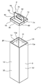
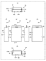
- FIG. 1 is a perspective view showing an appearance of a packaging box according to Embodiment 1.
- FIG. It is a perspective view which shows the state which decomposed
- FIG. 3 is a diagram showing a packaging box according to Embodiment 1.
- FIG. 4 is a cross-sectional view of the packaging box along line 4-4 in FIG. It is an expanded view which shows the state which expand
- FIG. FIG. 3 is a development view illustrating a state in which the lid according to Embodiment 1 is developed. It is sectional drawing for demonstrating the procedure which attaches a cover body to the 1st opening part of a box main body.
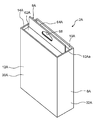
- FIG. 6 is a perspective view showing an appearance of a packaging box according to Embodiment 2.
- FIG. 6 is a diagram showing a packaging box according to Embodiment 2.
- FIG. It is sectional drawing of the packaging box by the 11-11 line in (a) of FIG. It is an expanded view which shows the state which expand
- FIG. 6 is a development view showing a state in which a lid according to Embodiment 2 is developed.
- FIG. FIG. 10 is a perspective view showing an appearance of a packaging box according to Embodiment 3.
- FIG. 5 is a diagram showing a packaging box according to a third embodiment.
- FIG. 16 is a cross-sectional view of the packaging box taken along line 16-16 in FIG. It is an expanded view which shows the state which expand
- FIG. FIG. 10 is a development view showing a state where a lid according to Embodiment 3 is developed. It is a perspective view which shows the external appearance of the packaging box which concerns on Embodiment 4.
- FIG. It is a figure which shows the packaging box which concerns on Embodiment 4.
- FIG. 21 is a cross-sectional view of the packaging box taken along line 21-21 in FIG. It is an expanded view which shows the state which expand
- FIG. It is an expanded view which shows the state which expand
- FIG. It is a figure which shows the packaging box which concerns on Embodiment 5.
- FIG. It is an expanded view which shows the state which expand
- FIG. It is a figure explaining the opening / closing operation
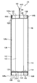
- FIG. 1 is a perspective view showing an appearance of a packaging box 2 according to Embodiment 1.
- FIG. 2 is a perspective view showing a state where the packaging box 2 according to Embodiment 1 is disassembled.
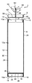
- FIG. 3 is a diagram showing the packaging box 2 according to the first embodiment.
- 3 (a) is a front view of the packaging box 2
- FIG. 3 (b) is a rear view of the packaging box 2
- FIG. 3 (c) is a plan view of the packaging box 2.
- FIG. 3 (d) is a bottom view of the packaging box 2
- FIG. 3 (e) is a right side view of the packaging box 2
- FIG. 3 (f) is a packaging.
- FIG. 4 is a left side view of the work box 2.
- 4 is a cross-sectional view of the packaging box 2 taken along line 4-4 in FIG.
- the packaging box 2 is a box for packaging an article 4 (see FIG. 8A described later), and includes a box body 6 and a lid 8.
- the packaging box 2 is made of a transparent resin such as polyethylene terephthalate (PET) or vinyl chloride, and is a clear case in which the package 4 can be seen through from the outside.
- PET polyethylene terephthalate
- vinyl chloride vinyl chloride
- transparent may be transparent enough to allow the user to visually observe the package 4 from the outside of the packaging box 2, and does not necessarily need to be completely transparent.
- the package 4 is, for example, a combination of a product displayed at a store and a rectangular parallelepiped paper package for storing the product.
- the products included in the package 4 include, for example, audio accessory products such as earphones and headphones, hairdressing products such as electric toothbrushes, small products such as batteries, daily necessaries such as cosmetics and daily goods, and foods such as confectionery. And various other products.
- the package for storing the product has a function for advertising the stored product and a function as a cushioning material for protecting the product.
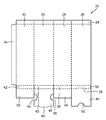
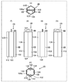
- FIG. 5 is a developed view showing a state in which the box body 6 according to the first embodiment is developed.
- the shape of the box body 6 is, for example, a square cylindrical shape, and has a cylindrical shape from the upper surface (upper surface in FIG. 4) to the lower surface (lower surface in FIG. 4). It extends.
- a square-shaped first opening 10 is provided on the upper surface of the box body 6.
- the peripheral portion 10 a of the first opening 10 is provided with a first folded portion 14 that is folded so as to overlap the inner surface 12 a of the side surface 12 of the box body 6. .
- the first folded portion 14 is provided over the entire circumference of the peripheral edge portion 10 a of the first opening 10.
- a square-shaped second opening 16 is provided on the lower surface of the box body 6.
- a second folded portion 18 that is folded so as to overlap the inner surface 12 a of the side surface 12 of the box body 6 is provided on the peripheral edge portion 16 a of the second opening portion 16.
- the second folded portion 18 is provided over the entire circumference of the peripheral edge portion 16 a of the second opening portion 16.
- a bottom cover portion 20 is provided on the lower surface of the box body 6 so as to cover the second opening portion 16 so as to be opened and closed.
- the bottom cover part 20 is provided so as to extend from the tip part 18 a of the second folded part 18.
- the box body 6 is assembled by folding a single sheet 22 shown in FIG. 5 along a fold line (broken line shown in FIG. 5).
- the sheet 22 is a sheet made of a transparent resin having a thickness of 0.3 mm, for example, and is obtained by cutting an original sheet (not shown) of the sheet 22 with a press machine or the like.
- the sheet 22 includes, as regions, a first folded piece 24, four side portions 26, 28, 30, 32, a connection piece 34, four second folded pieces 36, 38, 40, 42, an outer flap 44, and an inner side.
- a flap 46, an outer flap 48 and an inner flap 50 are provided.
- Each of the four side portions 26 to 32 is an area for constituting the side surface 12 of the box body 6 and is folded into a square cylinder when the box body 6 is assembled by folding the sheet 22.
- the four side surfaces 26 to 32 are respectively a rear surface of the box body 6 (see FIG. 3B), a left side surface of the box body 6 (see FIG. 3F), and a front surface of the box body 6 (see FIG. 3). (See (a)) and the right side of the box body 6 (see (e) in FIG. 3).
- the connection piece 34 is connected to one side of the side surface portion 32. When the box body 6 is assembled by bending the sheet 22, the connection piece 34 is bonded to the inner surface of the side surface portion 26 adjacent to the side surface portion 32 with an adhesive or the like in a state of being bent substantially vertically.
- the first folded piece 24 is an area for constituting the first folded portion 14 of the box body 6, and is connected so as to straddle the upper sides of the four side surface portions 26 to 32.
- the first folded piece 24 is folded back about 180 ° so as to overlap the inner surface 12 a of the side surface 12 of the box body 6.
- Each of the four second folded pieces 36 to 42 is an area for constituting the second folded portion 18 of the box body 6, and is connected to the lower side of each of the four side surface portions 26 to 32.
- Each of the four second folded pieces 36 to 42 is folded back by about 180 ° so as to overlap the inner surface 12 a of the side surface 12 of the box body 6 when the box body 6 is assembled by folding the sheet 22.
- the four second folded pieces 36 to are not divided into four, but are divided into four parts by folding lines as one second folded piece in the same manner as the first folded piece 24. It may be formed so as to straddle the lower side of each of the portions 26 to 32.
- Each of the outer flap 44, the inner flap 46, the outer flap 48, and the inner flap 50 is an area for constituting the bottom lid portion 20 of the box body 6.
- the outer flap 44, the inner flap 46, the outer flap 48, and the inner flap 50 are each connected to the lower side of each of the second folded pieces 36-42.
- a semicircular cutout 52 is formed on the lower side of the outer flap 44.
- Semicircular notches 54 and 56 are formed on both sides of the outer flap 48, respectively.
- a slit 58 is formed at the boundary between the outer flap 44 and the second folded piece 36.
- a projecting piece 60 to be inserted into the slit 58 is formed on the lower side of the outer flap 48.
- each of the outer flap 44, the inner flap 46, the outer flap 48, and the inner flap 50 is bent as follows. First, each of the inner flaps 46 and 50 is bent substantially vertically so as to cover the second opening 16.
- the outer flap 44 is bent substantially vertically so as to cover the inner flaps 46 and 50 from the outside.
- the outer flap 48 is bent substantially vertically so as to cover the outer flap 44 from the outside.
- the projecting piece 60 is inserted into the slit 58.
- the bottom lid 20 is formed, and the second opening 16 of the box body 6 is closed by the bottom lid 20.
- the bottom cover portion 20 is disposed at a position slightly deeper on the first opening portion 10 side than the peripheral edge portion 16 a of the second opening portion 16.
- the second opening 16 of the box body 6 When the second opening 16 of the box body 6 is opened, first, for example, the user pulls the outer flap 48 outward with the fingers hooked on the notches 54 and 56, respectively. 60 is withdrawn from the slit 58. Next, after the user pulls the outer flap 44 outward with the finger hooked on the notch 52, each of the inner flaps 46, 50 is pulled outward. In this way, as shown in FIG. 8B described later, the second opening 16 is opened.
- FIG. 6 is a development view showing a state where the lid body 8 according to the first embodiment is developed.
- the lid 8 is for covering the first opening 10 of the box body 6 so that it can be opened and closed, and is detachably attached to the first opening 10.
- the lid 8 has an upper lid 62, a hanging part 64, and an insertion part 66.
- the shape of the upper lid portion 62 is, for example, a substantially square plate shape.
- the upper lid 62 is arranged so as to cover the first opening 10 of the box body 6.
- the peripheral edge portion 62 a of the upper lid portion 62 is disposed so as to be close to (or in contact with) the inner surface 12 a of the side surface 12 of the box body 6.
- the upper lid portion 62 is disposed at a position slightly recessed toward the second opening portion 16 side from the peripheral edge portion 10 a of the first opening portion 10.
- the hanging portion 64 extends substantially vertically upward from the upper surface of the upper lid portion 62.
- a hanging through hole 68 is formed in the hanging portion 64. For example, by hooking a hook (not shown) for suspending the packaging box 2 into the suspension through-hole 68, the packaging box 2 can be displayed at the store with the hook suspended.
- the insertion portion 66 is provided over the entire periphery of the peripheral edge portion 62 a of the upper lid portion 62, and extends substantially vertically upward from the peripheral edge portion 62 a of the upper lid portion 62.
- the insertion portion 66 is inserted between the first folded portion 14 of the box body 6 and the inner surface 12 a of the side surface 12 of the box body 6.
- the lid 8 is assembled by folding one sheet 70 shown in FIG. 6 along a fold line (broken line shown in FIG. 6).
- the sheet 70 is a sheet made of a transparent resin having a thickness of 0.3 mm, for example, and is obtained by cutting an original sheet (not shown) of the sheet 70 with a press machine or the like.
- the sheet 70 has insertion pieces 72, 74, and 76, an upper lid piece 78, hanging pieces 80 and 82, an upper lid piece 84, and insertion pieces 86, 88, and 90 as regions.
- the hanging pieces 80 and 82 are regions for constituting the hanging portion 64 of the lid body 8, and are folded so as to overlap each other when the lid body 8 is assembled by folding the sheet 70.
- Through holes 92 and 94 are formed in the hanging pieces 80 and 82, respectively. These through holes 92 and 94 are overlapped with each other to form a hanging through hole 68.
- the upper lid pieces 78 and 84 are regions for constituting the upper lid portion 62 of the lid body 8, and are folded substantially vertically when the lid body 8 is assembled by folding the sheet 70.
- the insertion pieces 72 to 76 and 86 to 90 are regions for constituting the insertion portion 66 of the lid body 8 and are bent substantially vertically when the lid body 8 is assembled by folding the sheet 70.
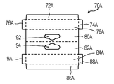
- FIGS. 4, 7 ⁇ / b> A, and 7 ⁇ / b> B are cross-sectional views for explaining a procedure for attaching the lid 8 to the first opening 10 of the box body 6.
- the upper lid portion 62 of the lid body 8 is placed in the direction indicated by the arrow P in FIG. Into the inside of the box body 6. At this time, as shown in FIG. 7B, the insertion portion 66 of the lid 8 comes close to (or contacts) the inner surface 12 a of the side surface 12 of the box body 6.
- the lid 8 is pulled up toward the outside of the box body 6 in the direction indicated by the arrow Q in FIG. 7B.
- the insertion portion 66 of the lid body 8 is inserted between the first folded portion 14 and the inner surface 12 a of the side surface 12 of the box body 6, whereby the lid body 8 is moved to the box body 6.
- the first opening 10 is attached.
- FIGS. 8A and 8B are cross-sectional views for explaining the procedure for taking out the article 4 from the packaging box 2.
- the lid 8 is attached to the first opening 10 of the box body 6 as described above, so that the article to be packaged 4 is attached to the packaging box 2.
- the article to be packaged 4 is disposed in a space surrounded by the side surface 12, the lid body 8, and the bottom lid portion 20 of the box body 6.
- the lid body 8 is directed toward the article to be packaged 4 in the direction indicated by the arrow R in FIG. Push in towards the opening 16).
- the insertion portion 66 of the lid body 8 is pulled out from between the first folded portion 14 and the inner surface 12 a of the side surface 12 of the box body 6.
- the lid 8 is removed from the first opening 10 of the box body 6, and the first opening 10 of the box body 6 is opened.
- the lid 8 is further pushed toward the package 4 in the direction indicated by the arrow S in FIG. 8B in a state where the lower surface of the upper lid 62 of the lid 8 is in contact with the upper surface of the package 4.
- the article 4 to be packaged is taken out of the packaging box 2 from the second opening 16 of the box body 6 in the direction indicated by the arrow T in FIG. 8B.
- the lid 8 is attached to the first opening 10 of the box body 6 with the article 4 to be packaged accommodated inside the box body 6.
- the packaging object 4 may be stored in the packaging box 2 from the second opening 16 in a state of being attached to the first opening 10 of the sixth.
- the packaging object 4 having substantially the same shape as the space formed by being surrounded by the side surface 12, the lid body 8, and the bottom lid portion 20 of the box body 6 can be stored in the packaging box 2.
- the box body 6 is provided on the peripheral edge portion 10 a of the first opening 10 and is folded back so as to overlap the inner surface 12 a of the side surface 12 of the box body 6.
- the folded portion 14 is provided.
- the lid body 8 is provided on the peripheral edge portion 62 a of the upper lid portion 62, and has an insertion portion 66 that is inserted between the first folded portion 14 and the inner surface 12 a of the side surface 12 of the box body 6.
- the lid 8 is pulled up toward the outside of the box body 6 by a relatively simple operation.
- the body 8 can be easily attached to the first opening 10 of the box body 6.
- the lid 8 can be easily removed from the first opening 10 of the box body 6 by a relatively simple operation of pushing the lid 8 attached to the first opening 10 toward the second opening 16. Can be removed. In this way, the lid body 8 can be easily attached to and detached from the box body 6.
- the first folded piece 24 is connected so as to straddle the upper sides of the four side portions 26 to 32. Since the sheet 22 has such a shape, when the raw material of the sheet 22 is cut with a press machine or the like, for example, an outer flap and an inner flap for constituting the upper lid portion are respectively connected to the four side surface portions 26 to 32. Compared to the conventional packaging box formed on the upper side, the material discarded can be reduced by about 19%.
- the first folded portion 14 is provided over the entire circumference of the peripheral edge portion 10 a of the first opening 10. Thereby, the intensity
- the box body 6 is further provided over the entire periphery of the peripheral edge portion 16 a of the second opening 16 and folded back so as to overlap the inner surface 12 a of the side surface 12 of the box body 6.
- the second folded portion 18 is provided. Thereby, the intensity
- the packaging box 2 can be stably placed by this edge. Thereby, for example, the packaging box 2 can be displayed at the store in a state where the packaging box 2 is placed on a showcase or the like.
- the to-be-packaged object 4 is the state in which the cover body 8 is pushed toward the 2nd opening part 16 in the state which the bottom cover part 20 has open
- the second opening 16 is disposed so as to be taken out of the packaging box 2. Thereby, the article 4 to be packaged can be easily taken out of the packaging box 2.
- the box body 6 and the lid body 8 are each made of a transparent resin. Thereby, the user can visually observe the article 4 to be packaged from the outside of the packaging box 2. Further, since the first opening 10 of the box body 6 is not provided with the conventional inner flap or the like as described in the background art section, the packaging box 2 is viewed from above (from the lid 8 side). ) When visually observed, the above-described inner flaps and the like are not seen through. Thereby, the design property of the packaging box 2 can be improved.
- FIG. 9 is a perspective view showing an appearance of the packaging box 2A according to the second embodiment.
- FIG. 10 shows a packaging box 2A according to the second embodiment. 10A is a front view of the packaging box 2A, FIG. 10B is a rear view of the packaging box 2A, and FIG. 10C is a plan view of the packaging box 2A.
- FIG. 10 (d) is a bottom view of the packaging box 2A, FIG. 10 (e) is a right side view of the packaging box 2A, and FIG. 10 (f) is a packaging. It is a left view of the box 2A.
- FIG. 11 is a cross-sectional view of the packaging box 2A taken along line 11-11 in FIG.
- FIG. 12 is a development view showing a state where the box body 6A according to the second embodiment is developed.
- the shape of the box body 6A is different between the present embodiment and the first embodiment. That is, as shown in FIGS. 9 and 10, in the present embodiment, the box body 6 ⁇ / b> A has a rectangular cylindrical shape. Similar to the first embodiment, the peripheral portion 10Aa of the first opening 10A of the box body 6A is provided with a first folded portion 14A that is folded so as to overlap the inner surface 12Aa of the side surface 12A of the box body 6A. It has been. Furthermore, a second folded portion 18A that is folded so as to overlap the inner surface 12Aa of the side surface 12A of the box body 6A is provided at the peripheral edge portion 16Aa of the second opening 16A of the box body 6A.
- the box body 6A is assembled by folding one sheet 22A shown in FIG. 12 along a fold line (broken line shown in FIG. 12).
- the sheet 22A includes, as regions, a first folded piece 24A, four side portions 26A, 28A, 30A, 32A, a connection piece 34, four second folded pieces 36A, 38A, 40A, 42A, an outer flap 44A, and an inner side.
- a flap 46A, an outer flap 48A, and an inner flap 50A are provided.
- each of the four side surfaces 26A to 32A is an area for configuring the side surface 12A of the box body 6A.
- the first folded piece 24A is an area for configuring the first folded portion 14A of the box body 6A.
- Each of the four second folded pieces 36A to 42A is an area for constituting the second folded portion 18A of the box body 6A.
- Each of the outer flap 44A, the inner flap 46A, the outer flap 48A, and the inner flap 50A is an area for constituting the bottom lid portion 20A of the box body 6A.
- FIG. 13 is a development view showing a state where the lid 8A according to the second embodiment is developed.
- the lid body 8A has an upper lid portion 62A, a hanging portion 64A, and an insertion portion 66A.
- the shape of the lid 8A is different. That is, as shown in FIGS. 9 and 10, in the present embodiment, the shape of the upper lid portion 62A is a substantially rectangular plate shape.
- the lid 8A is assembled by folding one sheet 70A shown in FIG. 13 along a fold line (broken line shown in FIG. 13).
- the sheet 70A includes insertion pieces 72A, 74A, and 76A, an upper cover piece 78A, hanging pieces 80A and 82A, an upper cover piece 84A, and insertion pieces 86A, 88A, and 90A as regions.
- the suspended pieces 80A and 82A are regions for configuring the suspended portion 64A of the lid 8A.
- the upper lid pieces 78A and 84A are regions for constituting the upper lid portion 62A of the lid body 8A.
- the insertion pieces 72A to 76A and 86A to 90A are regions for constituting the insertion portion 66A of the lid 8A.
- suspension through-hole 68 formed by the through-holes 92 and 94 of the suspension pieces 80A and 82A, the procedure for attaching the lid 8A, and the procedure for taking out the package are the same as in the first embodiment. The description is omitted.
- FIG. 14 is a perspective view showing an appearance of the packaging box 2B according to the third embodiment.
- FIG. 15 shows a packaging box 2B according to the third embodiment.
- 15A is a front view of the packaging box 2B
- FIG. 15B is a rear view of the packaging box 2B
- FIG. 15C is a plan view of the packaging box 2B.
- D) of FIG. 15 is a bottom view of the packaging box 2B
- e) of FIG. 15 is a right side view of the packaging box 2B
- (f) of FIG. It is a left view of the box 2B.
- FIG. 16 is a cross-sectional view of the packaging box 2B taken along line 16-16 in FIG.
- FIG. 17 is a development view showing a state in which the box body 6B according to the third embodiment is developed.
- the shape of the box body 6B is different between the present embodiment and the first embodiment. That is, as shown in FIGS. 14 and 15, in the present embodiment, the shape of the box body 6B is a regular hexagonal cylinder. Similar to the first embodiment, the peripheral portion 10Ba of the first opening 10B of the box body 6B is provided with a first folded portion 14B that is folded back so as to overlap the inner surface 12Ba of the side surface 12B of the box body 6B. It has been. Further, a second folded portion 18B that is folded back so as to overlap the inner surface 12Ba of the side surface 12B of the box body 6B is provided at the peripheral edge portion 16Ba of the second opening 16B of the box body 6B.
- the box body 6B is assembled by folding one sheet 22B shown in FIG. 17 along a fold line (broken line shown in FIG. 17).
- the sheet 22B includes, as regions, a first folded piece 98, six side portions 100, 102, 104, 106, 108, 110, a connection piece 34, and six second folded pieces 112, 114, 116, 118, 120. , 122, outer flap 124, inner flaps 126, 128, outer flap 130 and inner flaps 132, 134.
- Each of the six side surfaces 100 to 110 is an area for constituting the side surface 12B of the box body 6B, and is folded into a regular hexagonal cylinder when the box body 6B is assembled by folding the sheet 22B.
- the first folded piece 98 is an area for configuring the first folded portion 14B of the box body 6B, and is connected so as to straddle the upper sides of the six side surface portions 100 to 110.
- the first folded piece 98 is folded back by about 180 ° so as to overlap the inner surface 12Ba of the side surface 12B of the box body 6B.
- Each of the six second folded pieces 112 to 122 is an area for constituting the second folded portion 18B of the box body 6B, and is connected to the lower side of each of the six side surface portions 100 to 110.
- Each of the six second folded pieces 112 to 122 is folded back by about 180 ° so as to overlap the inner surface 12Ba of the side surface 12B of the box body 6B when the box body 6B is assembled by folding the sheet 22B.
- Each of the outer flap 124, the inner flaps 126 and 128, the outer flap 130, and the inner flaps 132 and 134 is an area for constituting the bottom lid portion 20B of the box body 6B.
- the outer flap 124, the inner flaps 126, 128, the outer flap 130, and the inner flaps 132, 134 are each connected to the lower side of each of the second folded pieces 112-122.
- Semicircular notches 136 and 138 are formed on both sides of the outer flap 124, respectively.
- Semi-circular cutouts 140 and 142 are formed on both sides of the outer flap 130, respectively.
- a slit 144 is formed at the boundary between the outer flap 124 and the second folded piece 112.
- a projecting piece 146 to be inserted into the slit 144 is formed on the lower side of the outer flap 130.
- each of the outer flap 124, the inner flaps 126 and 128, the outer flap 130, and the inner flaps 132 and 134 is bent as follows. First, each of the inner flaps 126, 128, 132, 134 is bent substantially vertically so as to cover the second opening 16B. The outer flap 124 is bent substantially vertically so as to cover each of the inner flaps 126, 128, 132, and 134 from the outside. Further, the outer flap 130 is bent substantially vertically so as to cover the outer flap 124 from the outside. At this time, the protruding piece 146 is inserted into the slit 144.
- FIG. 18 is a development view showing a state where the lid 8B according to the third embodiment is developed.
- the lid body 8B has an upper lid portion 62B, a hanging portion 64B, and an insertion portion 66B. As shown in FIGS. 14 and 15, the shape of the lid 8B is different between the present embodiment and the first embodiment. That is, in the present embodiment, the shape of the upper lid portion 62B is a regular hexagonal substantially plate shape.
- the lid 8B is assembled by folding one sheet 70B shown in FIG. 18 along a fold line (broken line shown in FIG. 18).
- the sheet 70B has insertion pieces 148, 150, 152, 154, an upper lid piece 156, hanging pieces 158, 160, an upper lid piece 162, and insertion pieces 164, 166, 168, 170 as regions.
- the hanging pieces 158 and 160 are areas for configuring the hanging portion 64B of the lid 8B.
- the upper lid pieces 156 and 162 are regions for configuring the upper lid portion 62B of the lid body 8B.
- the insertion pieces 148 to 154 and 164 to 170 are regions for constituting the insertion portion 66B of the lid body 8B.
- the hanging through hole 68 formed by the through holes 92 and 94 of the hanging pieces 158 and 160, the procedure for attaching the lid 8B, and the procedure for taking out the package are the same as in the first embodiment. The description is omitted.
- FIG. 19 is a perspective view showing an appearance of a packaging box 2C according to the fourth embodiment.
- FIG. 20 shows a packaging box 2C according to the fourth embodiment.
- 20 (a) is a front view of the packaging box 2C
- FIG. 20 (b) is a rear view of the packaging box 2C
- FIG. 20 (c) is a plan view of the packaging box 2C.
- 20 (d) is a bottom view of the packaging box 2C
- FIG. 20 (e) is a right side view of the packaging box 2C
- FIG. 20 (f) is a packaging. It is a left view of the box 2C.
- FIG. 21 is a cross-sectional view of the packaging box 2C taken along line 21-21 in FIG.
- FIG. 22 is a development view showing a state where the box body 6C according to the fourth embodiment is developed.
- the shape of the box body 6C is different between the present embodiment and the first embodiment. That is, as shown in FIGS. 19 and 20, in the present embodiment, the shape of the box body 6C is a circular cylindrical shape.
- the peripheral portion 10Ca of the first opening 10C of the box body 6C is provided with a first folded portion 14C that is folded back so as to overlap the inner surface 12Ca of the side surface 12C of the box body 6C, as in the first embodiment. It has been.
- a second folded portion 18C that is folded so as to overlap the inner surface 12Ca of the side surface 12C of the box body 6C is provided at the peripheral edge portion 16Ca of the second opening 16C of the box body 6C.
- the box body 6C is assembled by folding one sheet 22C shown in FIG. 22 along a fold line (broken line shown in FIG. 22).
- the sheet 22 ⁇ / b> C includes a first folded piece 172, a side surface part 174, a connection piece 34, a second folded piece 176, an inner flap 178 and an outer flap 180 as regions.
- the side surface portion 174 is an area for configuring the side surface 12C of the box body 6C, and is bent into a circular cylindrical shape when the box body 6C is assembled by folding the sheet 22C.
- the first folded piece 172 is an area for configuring the first folded portion 14C of the box body 6C, and is connected to the upper side of the side surface portion 174.
- the first folded piece 172 is folded back by about 180 ° so as to overlap the inner surface 12Ca of the side surface 12C of the box body 6C.
- the second folded piece 176 is an area for configuring the second folded portion 18C of the box body 6C, and is connected to the lower side of the side surface portion 174.
- the second folded piece 176 is folded back by about 180 ° so as to overlap the inner surface 12Ca of the side surface 12C of the box body 6C.
- Each of the inner side flap 178 and the outer side flap 180 is an area
- Each of the inner flap 178 and the outer flap 180 is connected to the lower side of the second folded piece 176.
- Semicircular notches 184 and 186 are formed on both sides of the inner flap 178, respectively.
- Semicircular notches 188 and 190 are formed on both sides of the outer flap 180, respectively.
- a slit 182 is formed in the vicinity of the boundary between the inner flap 178 and the second folded piece 176.
- a projecting piece 192 to be inserted into the slit 182 is formed on the lower side of the outer flap 180.
- the inner flap 178 is bent substantially vertically so as to cover the second opening 16C.
- the outer flap 180 is bent substantially vertically so as to cover the inner flap 178 from the outside.
- the projecting piece 192 is inserted into the slit 182.
- FIG. 23 is a development view showing a state where the lid body 8C according to the fourth embodiment is developed.
- the lid body 8C has an upper lid part 62C, a hanging part 64C and an insertion part 66C.
- the shape of the lid 8C is different between the present embodiment and the first embodiment. That is, as shown in FIGS. 19 and 20, in the present embodiment, the shape of the upper lid portion 62C is a substantially circular plate.
- the lid 8C is assembled by folding one sheet 70C shown in FIG. 23 along a folding line (broken line shown in FIG. 23).
- the sheet 70 ⁇ / b> C has insertion pieces 194, 196, 198, an upper lid piece 200, hanging pieces 202, 204, an upper lid piece 206, and insertion pieces 208, 210, 212 as regions.
- the hanging pieces 202 and 204 are regions for configuring the hanging portion 64C of the lid 8C.
- the upper lid pieces 200 and 206 are areas for constituting the upper lid portion 62C of the lid body 8C.
- the insertion pieces 194 to 198 and 208 to 212 are regions for constituting the insertion part 66C of the lid 8C.
- FIG. 24 is a diagram showing a packaging box 2D.
- 24A is a front view of the packaging box 2D
- FIG. 20B is a rear view of the packaging box 2D
- FIG. 20C is a plan view of the packaging box 2D.
- D) of FIG. 20 is a bottom view of the packaging box 2D
- e) of FIG. 20 is a right side view of the packaging box 2D
- (f) of FIG. It is a left view of work box 2D.
- FIG. 25 is a developed view showing a state in which the box body 6D is developed.
- the shape of the outer flap 48D constituting the bottom lid portion 20D of the box body 6D is different from the outer flap 48 of the first embodiment. That is, as shown in FIGS. 24 and 25, the outer flap 48 ⁇ / b> D has a rectangular tab 61 that extends from the protruding piece 60 on the lower side. Further, the semicircular cutout portions 54 and 56 on both sides of the outer flap 48 are not formed. Since the other configuration is the same as that of the box body 6 shown in the first embodiment, detailed description thereof is omitted.
- the box body 6D is assembled by folding one sheet 22D shown in FIG. 25 along a fold line (broken line shown in FIG. 25).
- the tab 61 is formed by extending the protruding piece 60 downward.
- the tab 61 is bent outward by about 180 ° along a fold line (broken line shown in FIG. 25) between the tab 61 and the projecting piece 60.
- FIG. 26 is a diagram for explaining the opening operation of the bottom lid 20D.
- the user causes the tab 61 to move outward from the closed state of the bottom cover 20D (A in FIG. 26) (B: tab).
- the tab 61 By causing the tab 61 to move outward, the projecting piece 60 is pulled out from the slit 58 (C: open state).
- the user pulls the outer flap 44 outward with the finger hooked on the notch 52 of the outer flap 44, and pulls out each of the inner flaps 46, 50 to the second.
- the opening 16 is opened.
- a packaging box in which the bottom lid portion can be easily opened and closed can be obtained.
- the tabs 61 can also be formed by extending the protruding pieces 60, 146, 192 of the outer flaps 48A, 130, 180 of the packaging boxes 2A-2C shown in the second to fourth embodiments. Further, the shape of the tab 61 is not limited to the rectangular shape as shown in FIGS. 24 and 25, and may be, for example, a semicircular shape or a trapezoidal shape.
- Embodiments 1 to 5 have been described as examples of the technology disclosed in the present application. However, the technology in the present disclosure is not limited to this, and can also be applied to an embodiment in which changes, replacements, additions, omissions, and the like are appropriately performed. Also, it is possible to combine the components described in the first to fifth embodiments to form a new embodiment.
- the box body 6 (6A to 6D) and the lid body 8 (8A to 8D) are each made of transparent resin, but the present invention is not limited to this.
- the box body 6 (6A to 6D) may be made of a transparent resin
- the lid 8 (8A to 8D) may be made of paper.
- the packaging box 2 (2A to 2D) that complies with the rigid plastic packaging container regulations of California, USA is realized. Can do.
- the above regulations use 25% or more of recycled resin as a packaging box material when a product whose whole circumference is wrapped in a hard plastic packaging box is sold in California, USA.
- the resin material used as the packaging box material must be reduced by 10% or more.
- the cover 8 (8A to 8D) is made of paper, so that the entire periphery of the package 4 is not wrapped with hard plastic, so that the above-mentioned regulations can be met. .
- both the box body 6 (6A to 6D) and the lid 8 (8A to 8D) may be made of paper.
- the box body 6 (6A to 6D) and the lid body 8 (8A to 8D) may be made of opaque resin.
- the shape of the box body 6 (6A to 6D) is a square shape, a rectangular shape, a regular hexagonal shape, and a circular cylindrical shape.
- the shape is not limited to this, and for example, an elliptical cylindrical shape is used.
- a trapezoidal cylindrical shape or the like may be used, and an arbitrary shape may be used.
- the shape of the box body 6 (6A to 6D) is a cylindrical cylinder, but the present invention is not limited to this.
- the second opening 16 (16A to 16C) has the first shape.
- a trumpet-shaped cylinder larger than the opening 10 (10A to 10C) may be used.
- the cross-sectional area of the box body 6 (6A to 6D) is gradually increased from the first opening 10 (10A to 10C) to the second opening 16 (16A to 16C). it can.
- the first folded portion 14 (14A to 14C) is provided over the entire circumference of the peripheral edge portion 10a (10Aa to 10Ca) of the first opening 10 (10A to 10C).
- the present invention is not limited to this, and the peripheral edge portion 10a (10Aa to 10Ca) may be disposed only at least in part.
- the first folded portion 14 can be provided only on two opposite sides of the four sides of the peripheral edge portion 10a of the first opening 10.
- the present disclosure can be applied to a packaging box for packaging an article to be packaged.
- the present disclosure can be applied to audio accessory products such as headphones, beauty products such as electric toothbrushes, or clear cases for packaging small products such as batteries.
Abstract
Description
以下、図1~図8Bを参照しながら、実施の形態1について説明する。 (Embodiment 1)
The first embodiment will be described below with reference to FIGS. 1 to 8B.
[1-1-1.包装用箱の全体構成]
まず、図1~図4を参照しながら、包装用箱2の全体構成について説明する。図1は、実施の形態1に係る包装用箱2の外観を示す斜視図である。図2は、実施の形態1に係る包装用箱2を分解した状態を示す斜視図である。図3は、実施の形態1に係る包装用箱2を示す図である。図3の(a)は、包装用箱2の正面図であり、図3の(b)は、包装用箱2の背面図であり、図3の(c)は、包装用箱2の平面図であり、図3の(d)は、包装用箱2の底面図であり、図3の(e)は、包装用箱2の右側面図であり、図3の(f)は、包装用箱2の左側面図である。図4は、図3の(a)中の4-4線による包装用箱2の断面図である。 [1-1. Structure of packaging box]
[1-1-1. Overall structure of packaging box]
First, the overall configuration of the
次に、図1~図5を用いて、箱本体6の構成について説明する。図5は、実施の形態1に係る箱本体6を展開した状態を示す展開図である。 [1-1-2. Box body configuration]
Next, the configuration of the
次に、図1~図4及び図6を用いて、蓋体8の構成について説明する。図6は、実施の形態1に係る蓋体8を展開した状態を示す展開図である。 [1-1-3. Configuration of the lid]
Next, the configuration of the
次に、図4、図7A及び図7Bを参照しながら、蓋体8を箱本体6の第1の開口部10に取り付ける手順について説明する。図7A及び図7Bはそれぞれ、蓋体8を箱本体6の第1の開口部10に取り付ける手順を説明するための断面図である。 [1-2. Lid installation procedure]
Next, a procedure for attaching the
次に、図8A及び図8Bを参照しながら、被包装物4を包装用箱2の外部に取り出す手順について説明する。図8A及び図8Bはそれぞれ、被包装物4を包装用箱2の外部に取り出す手順を説明するための断面図である。 [1-3. Unpacking procedure]
Next, with reference to FIGS. 8A and 8B, a procedure for taking out the
次に、本実施の形態の包装用箱2により得られる効果について説明する。上述したように、本実施の形態において、箱本体6は、第1の開口部10の周縁部10aに設けられ、且つ、箱本体6の側面12の内面12aに重なるように折り返された第1の折り返し部14を有している。蓋体8は、上蓋部62の周縁部62aに設けられ、且つ、第1の折り返し部14と箱本体6の側面12の内面12aとの間に差し込まれる差し込み部66を有している。 [1-4. Effect]
Next, effects obtained by the
以下、図9~図13を用いて、実施の形態2を説明する。 (Embodiment 2)
The second embodiment will be described below with reference to FIGS.
[2-1-1.箱本体の構成]
まず、図9~図12を参照しながら、包装用箱2Aの箱本体6Aの構成について説明する。図9は、実施の形態2に係る包装用箱2Aの外観を示す斜視図である。図10は、実施の形態2に係る包装用箱2Aを示す図である。図10の(a)は、包装用箱2Aの正面図であり、図10の(b)は、包装用箱2Aの背面図であり、図10の(c)は、包装用箱2Aの平面図であり、図10の(d)は、包装用箱2Aの底面図であり、図10の(e)は、包装用箱2Aの右側面図であり、図10の(f)は、包装用箱2Aの左側面図である。図11は、図10の(a)中の11-11線による包装用箱2Aの断面図である。図12は、実施の形態2に係る箱本体6Aを展開した状態を示す展開図である。 [2-1. Structure of packaging box]
[2-1-1. Box body configuration]
First, the configuration of the
次に、図9~図11及び図13を用いて、蓋体8Aの構成について説明する。図13は、実施の形態2に係る蓋体8Aを展開した状態を示す展開図である。 [2-1-2. Configuration of the lid]
Next, the configuration of the
本実施の形態では、上記実施の形態1と同様の効果を得ることができる。 [2-2. Effect]
In the present embodiment, the same effect as in the first embodiment can be obtained.
以下、図14~図18を用いて、実施の形態3を説明する。 (Embodiment 3)
The third embodiment will be described below with reference to FIGS.
[3-1-1.箱本体の構成]
まず、図14~図17を参照しながら、包装用箱2Bの箱本体6Bの構成について説明する。図14は、実施の形態3に係る包装用箱2Bの外観を示す斜視図である。図15は、実施の形態3に係る包装用箱2Bを示す図である。図15の(a)は、包装用箱2Bの正面図であり、図15の(b)は、包装用箱2Bの背面図であり、図15の(c)は、包装用箱2Bの平面図であり、図15の(d)は、包装用箱2Bの底面図であり、図15の(e)は、包装用箱2Bの右側面図であり、図15の(f)は、包装用箱2Bの左側面図である。図16は、図15の(a)中の16-16線による包装用箱2Bの断面図である。図17は、実施の形態3に係る箱本体6Bを展開した状態を示す展開図である。 [3-1. Structure of packaging box]
[3-1-1. Box body configuration]
First, the configuration of the
次に、図14~図16及び図18を用いて、蓋体8Bの構成について説明する。図18は、実施の形態3に係る蓋体8Bを展開した状態を示す展開図である。 [3-1-2. Configuration of the lid]
Next, the configuration of the
本実施の形態では、上記実施の形態1と同様の効果を得ることができる。 [3-2. Effect]
In the present embodiment, the same effect as in the first embodiment can be obtained.
以下、図19~図23を用いて、実施の形態4を説明する。 (Embodiment 4)
Hereinafter, the fourth embodiment will be described with reference to FIGS.
[4-1-1.箱本体の構成]
まず、図19~図22を参照しながら、包装用箱2Cの箱本体6Cの構成について説明する。図19は、実施の形態4に係る包装用箱2Cの外観を示す斜視図である。図20は、実施の形態4に係る包装用箱2Cを示す図である。図20の(a)は、包装用箱2Cの正面図であり、図20の(b)は、包装用箱2Cの背面図であり、図20の(c)は、包装用箱2Cの平面図であり、図20の(d)は、包装用箱2Cの底面図であり、図20の(e)は、包装用箱2Cの右側面図であり、図20の(f)は、包装用箱2Cの左側面図である。図21は、図20の(a)中の21-21線による包装用箱2Cの断面図である。図22は、実施の形態4に係る箱本体6Cを展開した状態を示す展開図である。 [4-1. Structure of packaging box]
[4-1-1. Box body configuration]
First, the configuration of the
次に、図19~図21及び図23を用いて、蓋体8Cの構成について説明する。図23は、実施の形態4に係る蓋体8Cを展開した状態を示す展開図である。 [3-1-2. Configuration of the lid]
Next, the configuration of the
本実施の形態では、上記実施の形態1と同様の効果を得ることができる。 [3-2. Effect]
In the present embodiment, the same effect as in the first embodiment can be obtained.
[5-1.包装用箱の構成]
[5-1-1.箱本体の構成]
図24及び図25を参照しながら、実施の形態5に係る包装用箱2Dの箱本体6Dの構成について説明する。図24は、包装用箱2Dを示す図である。図24の(a)は、包装用箱2Dの正面図であり、図20の(b)は、包装用箱2Dの背面図であり、図20の(c)は、包装用箱2Dの平面図であり、図20の(d)は、包装用箱2Dの底面図であり、図20の(e)は、包装用箱2Dの右側面図であり、図20の(f)は、包装用箱2Dの左側面図である。図25は、箱本体6Dを展開した状態を示す展開図である。 (Embodiment 5)
[5-1. Structure of packaging box]
[5-1-1. Box body configuration]
The configuration of the
箱本体6Dは、実施の形態1の箱本体6と同様に、図25に示す1枚のシート22Dを折り曲げ線(図25中に示す破線)に沿って折り曲げることにより組み立てられる。タブ61は、図25に示すように、突片60を下方に延伸して形成されている。タブ61は、突片60との間の折り曲げ線(図25中に示す破線)で、約180°外側に折り曲げられる。そして、外側フラップ48Dを折り曲げて箱本体6Dの底蓋部20Dが形成されるとき、突片60及びタブ61のうち突片60と重なる部分は、突片60とともにスリット58に差し込まれる。そして、箱本体6の第2の開口部16が底蓋部20により閉じられる。 [5-1-2. Opening and closing operation of the bottom cover]
Similarly to the
本実施の形態では、上記実施の形態1と同様の効果に加えて、底蓋部の開閉が容易な包装用箱を得ることができる。なお、実施の形態2~4で示した包装用箱2A~2Cの外側フラップ48A、130、180のそれぞれの突片60、146、192を延伸させてタブ61を形成することもできる。また、タブ61の形状は図24及び図25に示すような矩形状に限られず、例えば半円形状や台形状であってもよい。 [5-2. Effect]
In the present embodiment, in addition to the same effects as those of the first embodiment, a packaging box in which the bottom lid portion can be easily opened and closed can be obtained. The
以上のように、本出願において開示する技術の例示として、実施の形態1~5を説明した。しかしながら、本開示における技術は、これに限定されず、適宜、変更、置き換え、付加、省略などを行った実施の形態にも適用可能である。また、上記実施の形態1~5で説明した各構成要素を組み合わせて、新たな実施の形態とすることも可能である。 (Other embodiments)
As described above,
4 被包装物
6,6A,6B,6C,6D 箱本体
8,8A,8B,8C 蓋体
10,10A,10B,10C 第1の開口部
10a,10Aa,10Ba,10Ca,16a,16Aa,16Ba,16Ca,62a 周縁部
12,12A,12B,12C 側面
12a,12Aa,12Ba,12Ca 内面
14,14A,14B,14C 第1の折り返し部
16,16A,16B,16C 第2の開口部
18,18A,18B,18C 第2の折り返し部
18a 先端部
20,20A,20B,20C,20D 底蓋部
22,22A,22B,22C,22D,70,70A,70B,70C シート
24,24A,98,172 第1の折り返し片
26,26A,28,28A,30,30A,32,32A,100,102,104,106,108,110,174 側面部
34 接続片
36,36A,38,38A,40,40A,42,42A,112,114,116,118,120,122,176 第2の折り返し片
44,44A,48,48A,48D,124,130,180 外側フラップ
46,46A,50,50A,126,128,132,134,178 内側フラップ
52,54,56,136,138,140,142,184,186,188,190 切り欠き部
58,144,182 スリット
60,146,192 突片
61 タブ
62,62A,62B,62C 上蓋部
64,64A,64B,64C 吊り下げ部
66,66A,66B,66C 差し込み部
68 吊り下げ用貫通孔
72,72A,74,74A,76,76A,86,86A,88,88A,90,90A,148,150,152,154,164,166,168,170,194,196,198,208,210,212 差し込み片
78,78A,84,84A,156,162,200,206 上蓋片
80,80A,82,82A,158,160,202,204 吊り下げ片
92,94 貫通孔
96 指 2, 2A, 2B, 2C, 2D Packaging box 4 Packaged items 6, 6A, 6B, 6C, 6D Box body 8, 8A, 8B, 8C Lid 10, 10A, 10B, 10C First opening 10a, 10Aa, 10Ba, 10Ca, 16a, 16Aa, 16Ba, 16Ca, 62a Peripheral portion 12, 12A, 12B, 12C Side surface 12a, 12Aa, 12Ba, 12Ca Inner surface 14, 14A, 14B, 14C First folded portion 16, 16A, 16B 16C 2nd opening 18, 18A, 18B, 18C 2nd folding | turning part 18a Tip part 20, 20A, 20B, 20C, 20D Bottom cover part 22, 22A, 22B, 22C, 22D, 70, 70A, 70B, 70C Sheets 24, 24A, 98, 172 First folded pieces 26, 26A, 28, 28A, 30, 30A, 32, 32A, 10 , 102, 104, 106, 108, 110, 174 Side surface 34 Connection piece 36, 36A, 38, 38A, 40, 40A, 42, 42A, 112, 114, 116, 118, 120, 122, 176 Second folding Pieces 44, 44A, 48, 48A, 48D, 124, 130, 180 outer flaps 46, 46A, 50, 50A, 126, 128, 132, 134, 178 inner flaps 52, 54, 56, 136, 138, 140, 142 , 184, 186, 188, 190 Notch portion 58, 144, 182 Slit 60, 146, 192 Protrusion piece 61 Tab 62, 62A, 62B, 62C Upper lid portion 64, 64A, 64B, 64C Suspension portion 66, 66A, 66B , 66C insertion portion 68 penetrating through holes 72, 72A, 74, 74A, 76, 76 86, 86A, 88, 88A, 90, 90A, 148, 150, 152, 154, 164, 166, 168, 170, 194, 196, 198, 208, 210, 212 Insertion piece 78, 78A, 84, 84A, 156, 162, 200, 206 Upper cover piece 80, 80A, 82, 82A, 158, 160, 202, 204 Hanging piece 92, 94 Through hole 96 Finger
Claims (9)
- 被包装物を包装するための包装用箱であって、
上面に第1の開口部を有する筒状の箱本体と、
前記第1の開口部を覆うように前記第1の開口部に着脱可能に取り付けられる蓋体と、を備え、
前記箱本体は、前記第1の開口部の周縁部の少なくとも一部に設けられ、前記箱本体の内面に重なるように折り返された第1の折り返し部を有し、
前記蓋体は、前記蓋体の周縁部の少なくとも一部に設けられ、前記第1の開口部に取り付けられる際には前記第1の折り返し部と前記箱本体の前記内面との間に差し込まれる差し込み部を有する、
包装用箱。 A packaging box for wrapping a packaged article,
A cylindrical box body having a first opening on the upper surface;
A lid that is detachably attached to the first opening so as to cover the first opening,
The box body includes a first folded portion that is provided on at least a part of the peripheral edge of the first opening and is folded so as to overlap the inner surface of the box body;
The lid is provided on at least a part of the peripheral edge of the lid, and is inserted between the first folded portion and the inner surface of the box body when attached to the first opening. Having an insertion part,
Packaging box. - 前記第1の折り返し部は、前記第1の開口部の前記周縁部の全周に亘って設けられている、
請求項1に記載の包装用箱。 The first folded portion is provided over the entire circumference of the peripheral edge of the first opening.
The packaging box according to claim 1. - 前記箱本体は、さらに、前記箱本体の下面に設けられた第2の開口部を有し、
前記蓋体は、前記第2の開口部に向けて押し込まれることにより、前記差し込み部が前記第1の折り返し部と前記箱本体の前記内面との間から引き抜かれ、前記被包装物を前記第2の開口部に向けて押し出すように構成される、
請求項1に記載の包装用箱。 The box body further has a second opening provided on the lower surface of the box body,
When the lid is pushed toward the second opening, the insertion portion is pulled out from between the first folded portion and the inner surface of the box body, and the packaged object is removed from the first opening. Configured to extrude towards the two openings,
The packaging box according to claim 1. - 前記箱本体は、さらに、
前記第2の開口部の周縁部の全周に亘って設けられ、前記箱本体の前記内面に重なるように折り返された第2の折り返し部と、
前記第2の折り返し部の先端部から延びるように設けられ、前記第2の開口部を開閉可能に覆う底蓋部と、を有する、
請求項3に記載の包装用箱。 The box body further includes:
A second folded portion that is provided over the entire circumference of the peripheral edge of the second opening and is folded so as to overlap the inner surface of the box body;
A bottom lid portion provided so as to extend from a distal end portion of the second folded portion and covering the second opening so as to be openable and closable.
The packaging box according to claim 3. - 前記底蓋部は、前記第2の折り返し部の先端部から延びる第1の外側フラップ及び第2の外側フラップを備えるとともに、前記第1の外側フラップと前記第2の折り返し部との間にスリットを有し、
前記第2の外側フラップは前記スリットに差し込まれる突片を有する、
請求項4に記載の包装用箱。 The bottom cover portion includes a first outer flap and a second outer flap extending from a tip portion of the second folded portion, and a slit between the first outer flap and the second folded portion. Have
The second outer flap has a protrusion inserted into the slit;
The packaging box according to claim 4. - 前記第2の外側フラップは、さらに、前記突片から延伸するタブを備え、
前記タブは、前記突片との境界で折り曲げられ、
前記タブの前記突片と重なる部分は、前記スリットに差し込まれる、
請求項5に記載の包装用箱。 The second outer flap further comprises a tab extending from the protruding piece,
The tab is bent at the boundary with the protruding piece,
The portion of the tab that overlaps the protruding piece is inserted into the slit.
The packaging box according to claim 5. - 前記箱本体及び前記蓋体はそれぞれ透明樹脂製である、
請求項1に記載の包装用箱。 The box body and the lid are each made of transparent resin,
The packaging box according to claim 1. - 前記箱本体は樹脂製であり、前記蓋体は紙製である、
請求項1に記載の包装用箱。 The box body is made of resin, and the lid is made of paper.
The packaging box according to claim 1. - 請求項1に記載の包装用箱に包装された被包装物。 A packaged item packaged in the packaging box according to claim 1.
Priority Applications (4)
| Application Number | Priority Date | Filing Date | Title |
|---|---|---|---|
| EP15842364.0A EP3196138B1 (en) | 2014-09-19 | 2015-08-25 | Packaging box and object packaged in said packaging box |
| JP2016548539A JP6754949B2 (en) | 2014-09-19 | 2015-08-25 | Packaging box and the object to be packaged in the packaging box |
| CN201580048780.XA CN106715278B (en) | 2014-09-19 | 2015-08-25 | Packaging box and the packed article packed by the packaging box |
| US15/442,053 US20170166361A1 (en) | 2014-09-19 | 2017-02-24 | Packaging box and object packaged in said packaging box |
Applications Claiming Priority (2)
| Application Number | Priority Date | Filing Date | Title |
|---|---|---|---|
| JP2014-191899 | 2014-09-19 | ||
| JP2014191899 | 2014-09-19 |
Related Child Applications (1)
| Application Number | Title | Priority Date | Filing Date |
|---|---|---|---|
| US15/442,053 Continuation US20170166361A1 (en) | 2014-09-19 | 2017-02-24 | Packaging box and object packaged in said packaging box |
Publications (1)
| Publication Number | Publication Date |
|---|---|
| WO2016042708A1 true WO2016042708A1 (en) | 2016-03-24 |
Family
ID=55532767
Family Applications (1)
| Application Number | Title | Priority Date | Filing Date |
|---|---|---|---|
| PCT/JP2015/004240 WO2016042708A1 (en) | 2014-09-19 | 2015-08-25 | Packaging box and object packaged in said packaging box |
Country Status (5)
| Country | Link |
|---|---|
| US (1) | US20170166361A1 (en) |
| EP (1) | EP3196138B1 (en) |
| JP (1) | JP6754949B2 (en) |
| CN (1) | CN106715278B (en) |
| WO (1) | WO2016042708A1 (en) |
Families Citing this family (5)
| Publication number | Priority date | Publication date | Assignee | Title |
|---|---|---|---|---|
| USD878204S1 (en) * | 2018-08-22 | 2020-03-17 | E.L.F. Cosmetics, Inc. | Loop label for a cosmetic product package |
| USD992410S1 (en) * | 2018-08-21 | 2023-07-18 | E.L.F. Cosmetics, Inc. | Cosmetic product package having a hang tab |
| USD873655S1 (en) * | 2018-08-21 | 2020-01-28 | E.L.F. Cosmetics, Inc. | Cosmetic product package having a hang tab |
| USD987426S1 (en) * | 2018-08-21 | 2023-05-30 | E.L.F. Cosmetics, Inc. | Cosmetic product hang tag |
| EP4365099A1 (en) * | 2022-11-03 | 2024-05-08 | Mayr-Melnhof Karton AG | Container and set for producing a container |
Citations (6)
| Publication number | Priority date | Publication date | Assignee | Title |
|---|---|---|---|---|
| DE2205085A1 (en) * | 1972-02-03 | 1973-08-16 | Kloeckner Werke Ag | Presentation box - of hard pvc film, made by only folding the parts together without adhesive |
| DE3216718A1 (en) * | 1981-05-13 | 1982-12-02 | Schwarz, Günter, 8804 Au, Zürich | Packaging container, especially of cardboard |
| JPS6126216Y2 (en) * | 1981-07-17 | 1986-08-06 | ||
| JPH03502439A (en) * | 1988-12-14 | 1991-06-06 | ブーシェ アラン | snap lock box |
| JPH11124126A (en) * | 1997-10-20 | 1999-05-11 | R Kyapa:Kk | Folding packaging box and its manufacture |
| JP2003040249A (en) * | 2001-08-03 | 2003-02-13 | Matsushita Electric Works Ltd | Electric appliance packing box |
Family Cites Families (12)
| Publication number | Priority date | Publication date | Assignee | Title |
|---|---|---|---|---|
| US2468123A (en) * | 1946-09-18 | 1949-04-26 | United Board & Carton Corp | Folding carton |
| US2970736A (en) * | 1957-10-24 | 1961-02-07 | Reynolds Metals Co | Container system |
| US3285496A (en) * | 1965-01-13 | 1966-11-15 | Barnhardt Mfg Co | Polygonal tubular container with reclosable end |
| DE19635190A1 (en) * | 1996-08-30 | 1998-03-05 | Danapak As | Packaging for bulk goods |
| US6349866B1 (en) * | 1999-02-13 | 2002-02-26 | Stone Container Corporation | Paperboard can with an integrated paperboard lid having a hinge on the lid |
| US6047878A (en) * | 1999-03-11 | 2000-04-11 | Sonoco Development, Inc. | Substantially paper container |
| EP1479613A1 (en) * | 2003-05-22 | 2004-11-24 | P.L.V. Spa | Cardboard container for solid, granular or pasty products, and manufacturing method thereof |
| ITMI20041084A1 (en) * | 2004-05-28 | 2004-08-28 | P L V Spa | CARDBOARD CONTAINER OBTAINED FROM A SINGLE DIE CUT |
| CA2765489C (en) * | 2009-06-23 | 2017-11-28 | Teruaki Iyori | Retort cup |
| JP2011240963A (en) * | 2010-05-19 | 2011-12-01 | Eiko:Kk | Container |
| US9090371B2 (en) * | 2010-08-10 | 2015-07-28 | Concept Packaging Service Limited | Cartons |
| US20140091102A1 (en) * | 2012-09-28 | 2014-04-03 | HLP Clear Packaging Products (USA), Inc. | Locking arrangement for sleeve-and-endcap package |
-
2015
- 2015-08-25 CN CN201580048780.XA patent/CN106715278B/en active Active
- 2015-08-25 EP EP15842364.0A patent/EP3196138B1/en not_active Not-in-force
- 2015-08-25 WO PCT/JP2015/004240 patent/WO2016042708A1/en active Application Filing
- 2015-08-25 JP JP2016548539A patent/JP6754949B2/en active Active
-
2017
- 2017-02-24 US US15/442,053 patent/US20170166361A1/en not_active Abandoned
Patent Citations (6)
| Publication number | Priority date | Publication date | Assignee | Title |
|---|---|---|---|---|
| DE2205085A1 (en) * | 1972-02-03 | 1973-08-16 | Kloeckner Werke Ag | Presentation box - of hard pvc film, made by only folding the parts together without adhesive |
| DE3216718A1 (en) * | 1981-05-13 | 1982-12-02 | Schwarz, Günter, 8804 Au, Zürich | Packaging container, especially of cardboard |
| JPS6126216Y2 (en) * | 1981-07-17 | 1986-08-06 | ||
| JPH03502439A (en) * | 1988-12-14 | 1991-06-06 | ブーシェ アラン | snap lock box |
| JPH11124126A (en) * | 1997-10-20 | 1999-05-11 | R Kyapa:Kk | Folding packaging box and its manufacture |
| JP2003040249A (en) * | 2001-08-03 | 2003-02-13 | Matsushita Electric Works Ltd | Electric appliance packing box |
Also Published As
| Publication number | Publication date |
|---|---|
| EP3196138A1 (en) | 2017-07-26 |
| EP3196138B1 (en) | 2018-08-01 |
| JPWO2016042708A1 (en) | 2017-06-29 |
| CN106715278B (en) | 2019-02-05 |
| CN106715278A (en) | 2017-05-24 |
| JP6754949B2 (en) | 2020-09-16 |
| US20170166361A1 (en) | 2017-06-15 |
| EP3196138A4 (en) | 2017-08-23 |
Similar Documents
| Publication | Publication Date | Title |
|---|---|---|
| WO2016042708A1 (en) | Packaging box and object packaged in said packaging box | |
| JP5799114B2 (en) | Smoking package | |
| USD808792S1 (en) | Hard shell, multi-article, reclosable package | |
| USD799212S1 (en) | Magnetic carrying case | |
| KR20180087242A (en) | Pack for consumer goods | |
| JP2016037301A (en) | Packing box | |
| JP6428481B2 (en) | Packaging bags and packages | |
| JP2005298050A (en) | Packaging device | |
| JP3179100U (en) | Hamburg wrapping paper | |
| JP6206332B2 (en) | Packing box | |
| JP2012162311A (en) | Packaging container | |
| KR101968978B1 (en) | Case for a cosmetic container | |
| JP3161284U (en) | Storage box | |
| JP6734648B2 (en) | Packaging box | |
| KR101554002B1 (en) | Box for packing | |
| KR101876122B1 (en) | A supporting body inserted inside packaging bag and packaging bag package comprising thereof | |
| JP6097482B2 (en) | Method for manufacturing paper packaging container | |
| JP6776990B2 (en) | Packaging boxes and blank sheets for packaging boxes | |
| JP5739688B2 (en) | Packaging box | |
| JP6496766B2 (en) | Interdental brush package | |
| JP2007069976A (en) | Carton box | |
| JP2008213857A (en) | Container for granular gum | |
| JP3196960U (en) | Packing box | |
| JP2021155074A (en) | Packing box | |
| USD699124S1 (en) | Package for manufacturer coupons |
Legal Events
| Date | Code | Title | Description |
|---|---|---|---|
| 121 | Ep: the epo has been informed by wipo that ep was designated in this application |
Ref document number: 15842364 Country of ref document: EP Kind code of ref document: A1 |
|
| ENP | Entry into the national phase |
Ref document number: 2016548539 Country of ref document: JP Kind code of ref document: A |
|
| REEP | Request for entry into the european phase |
Ref document number: 2015842364 Country of ref document: EP |
|
| WWE | Wipo information: entry into national phase |
Ref document number: 2015842364 Country of ref document: EP |
|
| NENP | Non-entry into the national phase |
Ref country code: DE |