WO2016035529A1 - 撮像装置、撮像装置の制御方法及び制御プログラム - Google Patents
撮像装置、撮像装置の制御方法及び制御プログラム Download PDFInfo
- Publication number
- WO2016035529A1 WO2016035529A1 PCT/JP2015/072892 JP2015072892W WO2016035529A1 WO 2016035529 A1 WO2016035529 A1 WO 2016035529A1 JP 2015072892 W JP2015072892 W JP 2015072892W WO 2016035529 A1 WO2016035529 A1 WO 2016035529A1
- Authority
- WO
- WIPO (PCT)
- Prior art keywords
- frame
- infrared light
- pixel data
- timing
- imaging
- Prior art date
- Legal status (The legal status is an assumption and is not a legal conclusion. Google has not performed a legal analysis and makes no representation as to the accuracy of the status listed.)
- Ceased
Links
Images













Classifications
-
- H—ELECTRICITY
- H04—ELECTRIC COMMUNICATION TECHNIQUE
- H04N—PICTORIAL COMMUNICATION, e.g. TELEVISION
- H04N23/00—Cameras or camera modules comprising electronic image sensors; Control thereof
- H04N23/10—Cameras or camera modules comprising electronic image sensors; Control thereof for generating image signals from different wavelengths
- H04N23/12—Cameras or camera modules comprising electronic image sensors; Control thereof for generating image signals from different wavelengths with one sensor only
-
- H—ELECTRICITY
- H04—ELECTRIC COMMUNICATION TECHNIQUE
- H04N—PICTORIAL COMMUNICATION, e.g. TELEVISION
- H04N23/00—Cameras or camera modules comprising electronic image sensors; Control thereof
- H04N23/20—Cameras or camera modules comprising electronic image sensors; Control thereof for generating image signals from infrared radiation only
-
- H—ELECTRICITY
- H04—ELECTRIC COMMUNICATION TECHNIQUE
- H04N—PICTORIAL COMMUNICATION, e.g. TELEVISION
- H04N23/00—Cameras or camera modules comprising electronic image sensors; Control thereof
- H04N23/60—Control of cameras or camera modules
-
- H—ELECTRICITY
- H04—ELECTRIC COMMUNICATION TECHNIQUE
- H04N—PICTORIAL COMMUNICATION, e.g. TELEVISION
- H04N23/00—Cameras or camera modules comprising electronic image sensors; Control thereof
- H04N23/60—Control of cameras or camera modules
- H04N23/667—Camera operation mode switching, e.g. between still and video, sport and normal or high- and low-resolution modes
-
- H—ELECTRICITY
- H04—ELECTRIC COMMUNICATION TECHNIQUE
- H04N—PICTORIAL COMMUNICATION, e.g. TELEVISION
- H04N23/00—Cameras or camera modules comprising electronic image sensors; Control thereof
- H04N23/70—Circuitry for compensating brightness variation in the scene
- H04N23/73—Circuitry for compensating brightness variation in the scene by influencing the exposure time
-
- H—ELECTRICITY
- H04—ELECTRIC COMMUNICATION TECHNIQUE
- H04N—PICTORIAL COMMUNICATION, e.g. TELEVISION
- H04N23/00—Cameras or camera modules comprising electronic image sensors; Control thereof
- H04N23/70—Circuitry for compensating brightness variation in the scene
- H04N23/74—Circuitry for compensating brightness variation in the scene by influencing the scene brightness using illuminating means
-
- H—ELECTRICITY
- H04—ELECTRIC COMMUNICATION TECHNIQUE
- H04N—PICTORIAL COMMUNICATION, e.g. TELEVISION
- H04N23/00—Cameras or camera modules comprising electronic image sensors; Control thereof
- H04N23/80—Camera processing pipelines; Components thereof
- H04N23/84—Camera processing pipelines; Components thereof for processing colour signals
- H04N23/843—Demosaicing, e.g. interpolating colour pixel values
-
- H—ELECTRICITY
- H04—ELECTRIC COMMUNICATION TECHNIQUE
- H04N—PICTORIAL COMMUNICATION, e.g. TELEVISION
- H04N25/00—Circuitry of solid-state image sensors [SSIS]; Control thereof
- H04N25/10—Circuitry of solid-state image sensors [SSIS]; Control thereof for transforming different wavelengths into image signals
- H04N25/11—Arrangement of colour filter arrays [CFA]; Filter mosaics
- H04N25/13—Arrangement of colour filter arrays [CFA]; Filter mosaics characterised by the spectral characteristics of the filter elements
- H04N25/131—Arrangement of colour filter arrays [CFA]; Filter mosaics characterised by the spectral characteristics of the filter elements including elements passing infrared wavelengths
-
- H—ELECTRICITY
- H04—ELECTRIC COMMUNICATION TECHNIQUE
- H04N—PICTORIAL COMMUNICATION, e.g. TELEVISION
- H04N25/00—Circuitry of solid-state image sensors [SSIS]; Control thereof
- H04N25/10—Circuitry of solid-state image sensors [SSIS]; Control thereof for transforming different wavelengths into image signals
- H04N25/11—Arrangement of colour filter arrays [CFA]; Filter mosaics
- H04N25/13—Arrangement of colour filter arrays [CFA]; Filter mosaics characterised by the spectral characteristics of the filter elements
- H04N25/134—Arrangement of colour filter arrays [CFA]; Filter mosaics characterised by the spectral characteristics of the filter elements based on three different wavelength filter elements
Definitions
- the present disclosure relates to an imaging device, an imaging device control method, and a control program.
- an image obtained by imaging a subject by this imaging method is a monochrome image.
- monochrome images it may be difficult to identify an object. If a color image can be captured even in an environment where there is no visible light, the object identification can be improved. For example, in a surveillance camera, it is desired to capture a color image even in an environment without visible light in order to improve the object identification.
- Patent Document 1 describes an imaging apparatus that can capture a color image even in an environment without visible light.
- an infrared projector is also used. If the technique described in Patent Document 1 is installed in the surveillance camera, it becomes possible to convert the subject into a color image and improve the object identification.
- An object of the embodiments is to provide an imaging apparatus, an imaging apparatus control method, and a control program that can reduce color misregistration that occurs when an object is imaged by irradiating a moving object with infrared light. To do.
- the infrared projector by the infrared projector, the first infrared light having the first wavelength associated with the first color of red, green and blue, red and green, A second infrared light having a second wavelength associated with a second color of blue and a third wavelength associated with a third color of red, green and blue;
- a projection control unit that controls the infrared projector so as to selectively project the third infrared light in this order, and the first infrared light is projected in at least a part of one frame period.
- the subject is imaged, a first frame is generated based on the first imaging signal, and the second infrared light is projected in at least a part of one frame period.
- the first to third frames are combined with an imaging unit that images the subject in a state where light is projected in at least a part of an image period and generates a third frame based on a third imaging signal.
- a video processing unit that generates a frame of the video signal, wherein the light projection control unit is configured to perform a first timing that is a center of a period during which the second infrared light is projected, and the first or first The interval between the first timing and the second timing which is the center of the period during which the infrared light is projected is the third timing which is the center of one frame period of the first or third frame.
- the imaging device is characterized in that the infrared projector is controlled so as to project the first to third infrared lights at a time shorter than the distance between the first and third infrared lights.
- the first infrared light having the first wavelength associated with the first color of red, green, and blue is projected in at least a part of one frame period.
- the subject is imaged while being projected for at least part of one frame period.
- a control method for an image pickup apparatus characterized in that it is set shorter than an interval between a first timing and a third timing which is the center of one frame period of the first or third frame.
- the infrared rays are used to cause the computer to project the first infrared light having the first wavelength associated with the first color of red, green, and blue.
- a first step of controlling the projector and an image of the subject by the imaging unit in a state where the first infrared light is projected in at least a part of one frame period A second step of generating a first frame; and a second infrared light having a second wavelength associated with a second color of red, green and blue following the first step.
- the second frame based on the second imaging signal.
- the imaging unit is caused to image the subject, Executing a sixth step of generating a third frame based on a third imaging signal and a seventh step of generating a frame of a video signal by combining the first to third frames; The interval between the first timing that is the center of the period during which the second infrared light is projected and the second timing that is the center of the period during which the first or third infrared light is projected, 1st timing and 1 of said 1st or 3rd frame
- a control program of the image pickup apparatus and setting shorter than the interval between the third timing is a central frame period is provided.
- the imaging apparatus control method, and the control program of the embodiment, it is possible to reduce a color shift that occurs when an object is imaged by irradiating a moving object with infrared light.
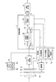
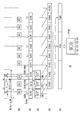
- FIG. 1 is a block diagram illustrating an overall configuration of an imaging apparatus according to an embodiment.
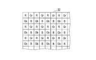
- FIG. 2 is a diagram illustrating an example of an arrangement of filter elements in a color filter used in the imaging apparatus according to the embodiment.
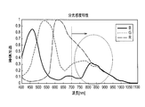
- FIG. 3 is a characteristic diagram showing spectral sensitivity characteristics of the wavelengths and relative sensitivities of the three primary color lights in the imaging unit constituting the imaging apparatus according to the embodiment.
- FIG. 4 is a characteristic diagram showing the relationship between the wavelength and the relative detection rate when the reflectance of the three primary colors from a predetermined substance is multiplied by the light receiving sensitivity of silicon.
- FIG. 5 is a block diagram showing a specific configuration of the previous signal processing unit 52 in FIG. FIG.
- FIG. 6 is a diagram illustrating a relationship between exposure and a frame of a video signal when the imaging apparatus according to the embodiment is operating in the normal mode.
- FIG. 7 is a diagram for describing demosaic processing when the imaging apparatus according to the embodiment is operating in the normal mode.
- FIG. 8 is a diagram illustrating a relationship between exposure and a frame of a video signal when the imaging apparatus of one embodiment is operating in the intermediate mode and the night vision mode.
- FIG. 9 is a diagram for explaining pre-signal processing when the imaging apparatus according to the embodiment is operating in the first intermediate mode.
- FIG. 10 is a diagram for describing the demosaic process when the imaging apparatus according to the embodiment is operating in the first intermediate mode.
- FIG. 11 is a diagram for describing pre-signal processing when the imaging apparatus according to the embodiment is operating in the second intermediate mode.
- FIG. 12 is a diagram for describing the demosaic process when the imaging apparatus according to the embodiment is operating in the second intermediate mode.
- FIG. 13 is a diagram for describing surrounding pixel addition processing when the imaging apparatus according to the embodiment is operating in the night vision mode.
- FIG. 14 is a diagram illustrating a frame that has been subjected to addition processing of surrounding pixels.
- FIG. 15 is a diagram for describing pre-signal processing when the imaging apparatus according to the embodiment is operating in the first night-vision mode.
- FIG. 16 is a diagram for describing the demosaic process when the imaging apparatus according to the embodiment is operating in the first night-vision mode.
- FIG. 17 is a diagram for describing pre-signal processing when the imaging apparatus according to the embodiment is operating in the second night-vision mode.
- FIG. 18 is a diagram for describing the demosaic process when the imaging apparatus according to the embodiment is operating in the second night-vision mode.
- FIG. 19 is a diagram for describing an example of mode switching in the imaging apparatus according to the embodiment.
- FIG. 20 is a diagram illustrating a state of each unit when the imaging apparatus according to the embodiment is set to each mode.
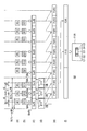
- FIG. 21 is a partial block diagram illustrating a first modification of the imaging apparatus according to an embodiment.
- FIG. 22 is a partial block diagram illustrating a second modification of the imaging apparatus according to the embodiment.
- FIG. 23 is a partial block diagram illustrating a third modification of the imaging apparatus according to the embodiment.
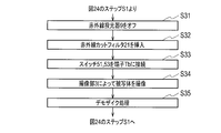
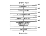
- FIG. 24 is a flowchart showing a video signal processing method.
- FIG. 25 is a flowchart showing specific processing of the normal mode shown in step S3 in FIG.
- FIG. 26 is a flowchart showing specific processing in the intermediate mode in step S4 in FIG.
- FIG. 27 is a flowchart showing specific processing of the night-vision mode in step S5 in FIG.
- FIG. 28 is a flowchart showing processing that the video signal processing program causes the computer to execute.
- FIG. 29 is a timing chart schematically showing a control method of the imaging apparatus that does not consider color shift reduction when generating a frame of a video signal by the imaging apparatus.
- FIG. 30 is a timing chart schematically showing a first example of a control method for an image pickup apparatus that reduces color misregistration when a frame of a video signal is generated by the image pickup apparatus.
- FIG. 31 is a timing chart schematically showing a second example of the control method of the image pickup apparatus for reducing the color misregistration when the frame of the video signal is generated by the image pickup apparatus.
- FIG. 32 is a timing chart schematically illustrating a third example of the control method of the imaging device that reduces the color misregistration when the frame of the video signal is generated by the imaging device.
- An imaging apparatus includes a normal mode suitable for an environment where there is sufficient visible light such as daytime, a night vision mode suitable for an environment where there is almost no visible light such as nighttime, and a visible mode.
- This is an imaging device capable of imaging in three modes, an intermediate mode suitable for an environment where light is slightly present.
- the intermediate mode is a first infrared light projection mode in which imaging is performed while projecting infrared light in an environment with little visible light.
- the night vision mode is a second infrared light projection mode in which imaging is performed while projecting infrared light in an environment where there is even less (almost) no visible light.
- the imaging device may have only one of the intermediate mode and the night vision mode.
- the imaging device may not have the normal mode.
- the imaging apparatus should just be equipped with the infrared light projection mode which images at least while projecting infrared rays.
- the light indicated by the one-dot chain line reflected from the subject is collected by the optical lens 1.
- the optical lens 1 has visible light in an environment in which visible light is sufficiently present, and infrared light in which an object reflects infrared light emitted from an infrared projector 9 described below in an environment with little visible light. Is incident.
- the imaging device includes a plurality of optical lenses.
- An optical filter 2 is provided between the optical lens 1 and the imaging unit 3.
- the optical filter 2 has two parts, an infrared cut filter 21 and a dummy glass 22.
- the optical filter 2 includes a state in which an infrared cut filter 21 is inserted between the optical lens 1 and the imaging unit 3 and a state in which a dummy glass 22 is inserted between the optical lens 1 and the imaging unit 3 by the driving unit 8. It is driven to either state.
- the imaging unit 3 includes an imaging element 31 in which a plurality of light receiving elements (pixels) are arranged in the horizontal direction and the vertical direction, and any one of red (R), green (G), and blue (B) corresponding to each light receiving element. And a color filter 32 in which filter elements of these colors are arranged.
- the image sensor 31 may be a CCD (Charge-Coupled Device) or a CMOS (Complementary Metal-Oxide Semiconductor).
- the color filter 32 has R, G, and B color filter elements arranged in an array called a Bayer array.
- the Bayer array is an example of a predetermined array of R, G, and B filter elements.
- the G filter element sandwiched between the R filter elements in each row is Gr
- the G filter element sandwiched between the B filter elements is Gb.
- FIG. 3 shows the spectral sensitivity characteristics of the wavelength of R light, G light, and B light and relative sensitivity in the imaging unit 3.
- the relative sensitivity is normalized to 1 at the maximum value.
- the drive unit 8 drives the optical filter 2 to insert the infrared cut filter 21 between the optical lens 1 and the imaging unit 3 based on the control by the control unit 7.
- the imaging unit 3 has sensitivity even in an infrared light region having a wavelength of 700 nm or more. Therefore, when the imaging device is operated in the intermediate mode or the night vision mode, the driving unit 8 removes the infrared cut filter 21 between the optical lens 1 and the imaging unit 3 based on the control by the control unit 7 and the dummy glass. The optical filter 2 is driven so that 22 is inserted.
- the imaging apparatus can obtain R, G, and B color information by using the sensitivity of the portion surrounded by the dashed ellipse in FIG.
- the reason why the dummy glass 22 is inserted is to make the optical path length the same as the optical path length when the infrared cut filter 21 is inserted.
- the infrared projector 9 includes projectors 91, 92, and 93 that project infrared light with wavelengths IR1, IR2, and IR3, respectively.
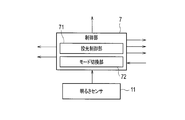
- the light projection control unit 71 in the control unit 7 performs control so as to selectively project infrared light with wavelengths IR1 to IR3 from the light projection units 91 to 93 in a time-sharing manner. .
- FIG. 4 shows the relationship between the wavelength and the relative detection rate when the reflectance at each wavelength is multiplied by the light receiving sensitivity of silicon when a material exhibiting each color of R, G, and B is irradiated with white light. Yes. Also in FIG. 4, the maximum value of the relative detection rate is normalized to 1.
- the reflected light at a wavelength of 780 nm is highly correlated with the reflected light of a material exhibiting an R color
- the reflected light at a wavelength of 870 nm is a reflection of a material exhibiting a B color.
- Correlation with light is high
- reflected light at a wavelength of 940 nm is highly correlated with reflected light of a material exhibiting G color.
- the wavelengths IR1, IR2, and IR3 of the infrared light projected by the light projecting units 91, 92, and 93 are set to 780 nm, 940 nm, and 870 nm. These wavelengths are examples of the wavelengths IR1 to IR3, and may be other than 780 nm, 940 nm, and 870 nm.
- the light projecting unit 91 irradiates the subject with infrared light having the wavelength IR1, and assigns an image signal obtained by imaging the light reflected from the subject to the R signal.
- the light projecting unit 93 irradiates the subject with infrared light having a wavelength IR2, and assigns a video signal obtained by imaging the light reflected from the subject to the G signal.
- the light projecting unit 92 irradiates the subject with infrared light having a wavelength IR3, and assigns a video signal obtained by imaging the light reflected from the subject to the B signal.
- the wavelength IR1 of 780 nm may be assigned to the R light
- the wavelength IR3 of 870 nm may be assigned to the G light
- the wavelength IR2 of 940 nm may be assigned to the B light.
- the wavelengths IR1, IR2, and IR3 can be arbitrarily assigned to the R light, G light, and B light.
- the wavelengths IR1, IR2, and IR3 that best reproduce the color of the subject are assigned to R light, G light, and B light, respectively.
- the control unit 7 controls imaging in the imaging unit 3 and each unit in the video processing unit 5.
- An electronic shutter control unit 73 in the control unit 7 controls the function of the electronic shutter in the imaging unit 3.
- the video signal captured by the imaging unit 3 is A / D converted by the A / D converter 4 and input to the video processing unit 5.
- the imaging unit 3 and the A / D converter 4 may be integrated.
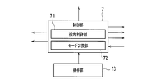
- the control unit 7 includes a mode switching unit 72 that switches between the normal mode, the intermediate mode, and the night vision mode.
- the mode switching unit 72 appropriately switches the operation in the video processing unit 5 as described later in correspondence with the normal mode, the intermediate mode, and the night vision mode.
- the video processing unit 5 and the control unit 7 may be integrated.
- the video processing unit 5 includes switches 51 and 53, a previous signal processing unit 52, and a demosaic processing unit 54.
- the switches 51 and 53 may be physical switches, or may be conceptual switches for switching between operation and non-operation of the previous signal processing unit 52.
- a video signal is input from the video processing unit 5 to the control unit 7 in order to detect the brightness of the video being captured.
- the previous signal processing unit 52 includes a surrounding pixel addition unit 521, a same-position pixel addition unit 522, and a synthesis unit 523.
- the video processing unit 5 generates R, G, and B primary color data and supplies them to the video output unit 6.
- the video output unit 6 outputs the three primary color data in a predetermined format to a display unit not shown.
- the video output unit 6 may output the R, G, and B signals as they are, or may convert the R, G, and B signals into luminance signals and color signals (or color difference signals) and output them.
- the video output unit 6 may output a composite video signal.
- the video output unit 6 may output a digital video signal or may output a video signal converted into an analog signal by a D / A converter.
- ⁇ Normal mode> In the normal mode, the control unit 7 causes the driving unit 8 to insert the infrared cut filter 21 between the optical lens 1 and the imaging unit 3.
- the light projection control unit 71 turns off infrared light projection by the infrared projector 9.
- the video signal imaged by the imaging unit 3 is converted into video data that is a digital signal by the A / D converter 4 and input to the video processing unit 5.
- the mode switching unit 72 controls the switches 51 and 53 to be connected to the terminal Tb.
- FIG. 6A shows the exposures Ex1, Ex2, Ex3,... Of the imaging unit 3.
- the exposures Ex1, Ex2, and Ex3 indicate the maximum exposure time.
- the shutter speed is determined by control in the electronic shutter control unit 73.
- FIG. 6 shows the timing at which each video signal frame is obtained. Based on an exposure (not shown) before the exposure Ex1, a frame F0 of the video signal is obtained after a predetermined time. Based on the exposure Ex1, a frame F1 of the video signal is obtained after a predetermined time. Based on the exposure Ex2, a frame F2 of the video signal is obtained after a predetermined time. The same applies to exposure Ex3 and thereafter.
- the frame frequency of the video signal is set to 30 frames / second, for example.
- the frame frequency of the video signal may be set as appropriate, such as 30 frames / second or 60 frames / second for the NTSC system and 25 frames / second or 50 frames / second for the PAL system.
- the frame frequency of the video signal may be 24 frames / second used in movies.
- the video data of each frame output from the A / D converter 4 is input to the demosaic processing unit 54 via the switches 51 and 53.
- the demosaic processing unit 54 performs demosaic processing on the input video data of each frame.
- the video processing unit 5 performs various video processing such as white balance correction and gain correction in addition to demosaic processing, and outputs R, G, and B primary color data.
- the demosaic processing in the demosaic processing unit 54 will be described with reference to FIG. 7A shows an arbitrary frame Fm of video data.
- the frame Fm is a frame composed of pixels in the effective video period.
- the number of pixels of the video data is, for example, horizontal 640 pixels and vertical 480 pixels in the VGA standard.
- the number of pixels of the frame Fm is significantly reduced, and the frame Fm is conceptually illustrated.
- the video data generated using the Bayer array imaging unit 3 is data in which R, G, and B pixel data are mixed in the frame Fm.
- the demosaic processing unit 54 generates R interpolation pixel data Ri obtained by calculating R pixel data at a pixel position where no R pixel data is present using surrounding R pixel data.
- the demosaic processing unit 54 generates an R frame FmR in which all the pixels in one frame shown in FIG. 7B are made up of R pixel data.
- the demosaic processing unit 54 generates G interpolated pixel data Gi obtained by calculating G pixel data at a pixel position where no G pixel data exists using surrounding G pixel data.
- the demosaic processing unit 54 generates a G frame FmG in which all the pixels of one frame shown in FIG.
- the demosaic processing unit 54 generates B interpolation pixel data Bi obtained by calculating B pixel data at a pixel position where B pixel data does not exist using surrounding B pixel data.
- the demosaic processing unit 54 generates a B frame FmB in which all the pixels of one frame shown in FIG.
- the demosaic processing unit 54 may use at least R pixel data when interpolating R pixel data, may use at least G pixel data when interpolating G pixel data, and B pixel data. When interpolation is performed, at least B pixel data may be used. In order to improve interpolation accuracy, the demosaic processing unit 54 may use pixel data of another color different from the color of the interpolation pixel data to be generated when interpolating R, G, and B pixel data. Good.
- R, G, and B pixel data can be interpolated even in pixels located at the upper, lower, left, and right ends of the frame Fm.
- the R frame FmR, G frame FmG, and B frame FmB generated by the demosaic processing unit 54 are output as R, G, and B primary color data.
- R, G, and B pixel data has been described in units of frames in order to facilitate understanding, but actually, the R, G, and B pixel data are sequentially output for each pixel.
- first intermediate mode> In the intermediate mode (first intermediate mode and second intermediate mode described later), the control unit 7 causes the driving unit 8 to insert the dummy glass 22 between the optical lens 1 and the imaging unit 3.
- the light projection controller 71 turns on the infrared light projection by the infrared light projector 9.
- the mode switching unit 72 controls the switches 51 and 53 to be connected to the terminal Ta.
- FIG. 8 shows a state of infrared light projection by the infrared projector 9.
- the control unit 7 divides one frame period of the normal mode into 1/3, and controls so as to project infrared light in the order of the light projecting units 91, 92, 93, for example.
- infrared light having a wavelength IR1 (780 nm) is irradiated on the subject in the first 3 period of one frame.
- the subject is irradiated with infrared light having a wavelength IR2 (940 nm).
- the subject is irradiated with infrared light having a wavelength IR3 (870 nm).
- the order of projecting infrared light with wavelengths IR1 to IR3 is arbitrary.
- the imaging unit 3 performs the exposure Ex1R having a high correlation with the R light.
- the imaging unit 3 performs the exposure Ex1G having a high correlation with the G light.
- the imaging unit 3 performs exposure Ex1B having a high correlation with the B light.
- the exposures Ex1R, Ex1G, Ex1B, Ex2R, Ex2G, Ex2B are exposures that combine exposure with visible light and exposure with infrared light.
- a frame F1IR1 corresponding to the exposure Ex1R, a frame F1IR2 corresponding to the exposure Ex1G, and a frame F1IR3 corresponding to the exposure Ex1B are obtained after a predetermined time. It is done.
- a frame F2IR1 corresponding to the exposure Ex2R, a frame F2IR2 corresponding to the exposure Ex2G, and a frame F2IR3 corresponding to the exposure Ex2B are obtained after a predetermined time. The same applies to exposures Ex3R, Ex3G, and Ex3B.
- the frame frequency of the imaging signal in FIG. 8C is 90 frames / second.
- one frame of the video signal in the normal mode is time-divided to project infrared light of wavelengths IR1 to IR3.
- ( The frame frequency of the imaging signal in c) is three times the frame frequency in the normal mode.
- one frame of a video signal having a frame frequency of 30 frames / second shown in FIG. 8D is generated based on the imaging signal of 3 frames shown in FIG.
- a frame F1IR is generated based on the frames F1IR1, F1IR2, and F1IR3
- a frame F2IR is generated based on the frames F2IR1, F2IR2, and F2IR3.
- the video data of each frame corresponding to the imaging signal shown in FIG. 8C output from the A / D converter 4 is input to the previous signal processing unit 52 via the switch 51.
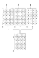
- FIG. 9A shows an arbitrary frame FmIR1 of the video data generated at the timing when the infrared light having the wavelength IR1 is projected.
- the R, B, Gr, and Gb pixel data in the frame FmIR1 is attached with a subscript 1 indicating that it is generated in a state where infrared light having the wavelength IR1 is projected.
- FIG. 9 shows an arbitrary frame FmIR2 of the video data generated at the timing when the infrared light having the wavelength IR2 is projected.
- the R, B, Gr, and Gb pixel data in the frame FmIR2 is attached with a subscript 2 indicating that it is generated in a state where infrared light having a wavelength IR2 is projected.
- FIG. 9 shows an arbitrary frame FmIR3 of the video data generated at the timing when the infrared light having the wavelength IR3 is projected.
- the R, B, Gr, and Gb pixel data in the frame FmIR3 has a subscript 3 indicating that it is generated in a state where infrared light having the wavelength IR3 is projected.
- the frame FmIR1 shown in FIG. 9A is video data generated in a state where infrared light having a wavelength IR1 having a high correlation with the R light is projected. Therefore, the R pixel data is projected.
- the pixel data corresponding to the infrared light and the pixel data B and G are pixel data not corresponding to the projected infrared light.
- the hatching attached to the B, Gr, and Gb pixel data means that the pixel data does not correspond to the projected infrared light.
- the frame FmIR2 shown in FIG. 9B is video data generated in a state where infrared light having a wavelength IR2 having a high correlation with the G light is projected, so that the G pixel data is projected.
- the pixel data corresponding to the infrared light, and the R and B pixel data are pixel data not corresponding to the projected infrared light.
- the hatching attached to the R and B pixel data means that the pixel data does not correspond to the projected infrared light.
- the frame FmIR3 shown in FIG. 9C is video data generated in a state where infrared light having a wavelength IR3 having a high correlation with the B light is projected, so that the B pixel data is projected.
- the pixel data corresponding to the infrared light, and the R and G pixel data are pixel data not corresponding to the projected infrared light.
- the hatching attached to the R, Gr, and Gb pixel data means pixel data that does not correspond to the projected infrared light.
- the same-position pixel addition unit 522 in the previous signal processing unit 52 individually adds the pixel data of R, Gr, Gb, and B at the same pixel position according to the following formulas (1) to (3) to obtain pixel data R123, Gr123, Gb123, and B123 are generated.
- the surrounding pixel addition unit 521 in the previous signal processing unit 52 does not operate.
- R123 ka ⁇ R1 + kb ⁇ R2 + kc ⁇ R3 (1)
- G123 kd ⁇ G1 + ke ⁇ G2 + kf ⁇ G3 (2)
- B123 kg ⁇ B1 + kh ⁇ B2 + ki ⁇ B3 (3)
- R1, G1, and B1 are R, G, and B pixel data in the frame FmIR1, R2, G2, and B2 are R, G, and B pixel data in the frame FmIR2, R3, G3, B3 is R, G, B pixel data in the frame FmIR3. ka to ki are predetermined coefficients.
- G123 in Formula (2) is Gr123 or Gb123.
- the same-position pixel adding unit 522 adds R, Gr, Gb, and B pixel data at the same pixel position with hatching to the respective pixel data with R, Gr, Gb, and B that are not hatched. Is added.
- the same-position pixel addition unit 522 adds the R pixel data at the same pixel position in the frames FmIR2 and FmIR3 to the R pixel data in the frame FmIR1 based on the equation (1) to generate the pixel data R123.
- red pixel data R123 is generated using only pixel data in a region corresponding to the red color filter in the light receiving element.
- the same-position pixel addition unit 522 adds the pixel data of Gr and Gb at the same pixel position in the frames FmIR1 and FmIR3 to the pixel data of Gr and Gb in the frame FmIR2 based on the equation (2), thereby obtaining pixel data G123. Is generated. That is, green pixel data G123 is generated using only pixel data in a region corresponding to the green color filter in the light receiving element.
- the same-position pixel adding unit 522 generates pixel data B123 by adding the B pixel data at the same pixel position in the frames FmIR1 and FmIR2 to the B pixel data in the frame FmIR3 based on the equation (3). That is, blue pixel data B123 is generated using only pixel data in a region corresponding to the blue color filter in the light receiving element.
- the combining unit 523 in the previous signal processing unit 52 generates a frame FmIR123 of the combined video signal shown in (d) of FIG. 9 based on the pixel data R123, Gr123, Gb123, and B123 generated at each pixel position. .
- the combining unit 523 selects and combines the pixel data R123 in the frame FmIR1, the pixel data Gr123 and Gb123 in the frame FmIR2, and the pixel data B123 in the frame FmIR3. Thereby, the synthesis unit 523 generates a frame FmIR123 of the synthesized video signal.
- the synthesis unit 523 generates a frame FmIR123 in which the pixel data R123, Gr123, Gb123, and B123 are arranged so as to have the same arrangement as the arrangement of the filter elements in the color filter 32.
- the video data of the frame FmIR123 is generated using the pixel data that is not hatched and the pixel data that is hatched.
- the reason why the pixel data at the same pixel position is added by the same position pixel addition unit 522 is as follows. Since the imaging is performed in an environment where visible light is present in the intermediate mode, the hatched pixel data includes respective color components based on exposure with visible light. Therefore, the sensitivity of each color can be increased by adding pixel data at the same pixel position.
- the video data of the frame FmIR123 mainly includes components based on the video signal exposed with visible light. If visible light and infrared light are mixed and there is a relatively large amount of infrared light, exposure with infrared light becomes dominant. In this case, the video data of the frame FmIR123 mainly includes components based on the video signal exposed with infrared light.
- the relationship between the coefficients ka, kb, and kc in equation (1) is ka> kb, kc, and the relationship between the coefficients kd, ke, and kf in equation (2).
- Kf> kd, ke, and in equation (3) the magnitude relationship between the coefficients kg, kh, ki is preferably kh> kg, ki. This is because the wavelength IR1 has a high correlation with the R light, the wavelength IR2 has a high correlation with the G light, and the wavelength IR3 has a high correlation with the B light.
- the R pixel data is mainly the R pixel data in the frame FmIR1
- the G pixel data is the G pixel data in the frame FmIR2
- the B pixel data is mainly the B pixel data in the frame FmIR3. it can.
- the video data of the frame FmIR123 output from the previous signal processing unit 52 is input to the demosaic processing unit 54 via the switch 53.
- the demosaic processing unit 54 performs demosaic processing on the video data of the input frame FmIR123, as in the normal mode.
- the video processing unit 5 performs various video processing such as white balance correction and gain correction in addition to demosaic processing, and outputs R, G, and B primary color data.
- the demosaic processing in the demosaic processing unit 54 will be described with reference to FIG. FIG. 10A shows a frame FmIR123.
- the demosaic processing unit 54 calculates the R pixel data at the pixel position where the R pixel data does not exist using the surrounding R pixel data, and generates the R interpolation pixel data R123i.
- the demosaic processing unit 54 generates an R frame FmIR123R in which all the pixels in one frame shown in FIG.
- the demosaic processing unit 54 calculates the G pixel data at the pixel position where the G pixel data does not exist using the surrounding G pixel data, and generates the G interpolation pixel data G123i.
- the demosaic processing unit 54 generates a G frame FmIR123G in which all the pixels of one frame shown in FIG.
- the demosaic processing unit 54 calculates the B pixel data at the pixel position where the B pixel data does not exist using the surrounding B pixel data, and generates the B interpolation pixel data B123i.
- the demosaic processing unit 54 generates a B frame FmIR123B in which all the pixels in one frame shown in FIG.
- the previous signal processing unit 52 In the normal mode, the previous signal processing unit 52 is disabled, and in the intermediate mode, the previous signal processing unit 52 may be operated except for the surrounding pixel adding unit 521. In the normal mode and the intermediate mode, the demosaic processing unit 54 in the video processing unit 5 and the signal processing unit such as white balance correction and gain correction can be shared.
- Second intermediate mode The operation in the second intermediate mode will be described with reference to FIGS. In the operation in the second intermediate mode, the description of the same part as the operation in the first intermediate mode is omitted.
- the frames FmIR1, FmIR2, and FmIR3 in (a) to (c) of FIG. 11 are the same as the frames FmIR1, FmIR2, and FmIR3 in (a) to (c) of FIG.
- the combining unit 523 selects and combines R1 which is R pixel data in the frame FmIR1, Gr2 and Gb2 which are G pixel data in the frame FmIR2, and B3 which is B pixel data in the frame FmIR3. As a result, the synthesis unit 523 generates a frame FmIR123 'of the synthesized video signal shown in FIG.
- the frame FmIR123 ' is video data obtained by collecting R, Gr, Gb, and B pixel data not hatched in the frames FmIR1, FmIR2, and FmIR3 into one frame.
- Only the pixel data for the green color using only the pixel data of the region corresponding to the green color filter in the selected state, and the pixel data of the region corresponding to the blue color filter in the state of projecting the infrared light having the wavelength IR3 are used.
- the pixel data is for blue.
- the synthesizing unit 523 generates a frame FmIR123 'in which the pixel data R1, Gr2, Gb2, and B3 are arranged so as to have the same arrangement as the arrangement of the filter elements in the color filter 32.
- the same-position pixel adding unit 522 sets the coefficient ka in Equation (1) to 1, the coefficients kb and kc to 0, the coefficient ke in Equation (2) to 1, the coefficients kd and kf to 0,
- the coefficient ki is 1 and the coefficients kg and kh are 0.
- the R pixel data in the frame FmIR1 the Gr and Gb pixel data in the frame FmIR2, and the B pixel data in the frame FmIR3 have the same values.
- the combining unit 523 selects the R pixel data in the frame FmIR1, the Gr and Gb pixel data in the frame FmIR2, and the B pixel data in the frame FmIR3. FmIR123 'can be generated.
- the front signal processing unit 52 In the second intermediate mode, the front signal processing unit 52 generates pixel data (hatched) with infrared light projected to generate pixel data having the same color as the pixel data. Video data of the frame FmIR123 ′ is generated using only (non-pixel data).
- the arithmetic processing can be simplified and the frame memory can be reduced.
- the demosaic processing in the demosaic processing unit 54 will be described with reference to FIG. FIG. 12A shows the frame FmIR123 '.
- the demosaic processing unit 54 calculates the R pixel data at the pixel position where the R pixel data does not exist using the surrounding R pixel data, and generates the R interpolation pixel data R1i.
- the demosaic processing unit 54 generates an R frame FmIR123′R in which all the pixels in one frame shown in FIG. 12B are made up of R pixel data.
- the demosaic processing unit 54 calculates the G pixel data at the pixel position where the G pixel data does not exist using the surrounding G pixel data, and generates the G interpolation pixel data G2i.
- the demosaic processing unit 54 generates a G frame FmIR123′G in which all the pixels in one frame shown in FIG.
- the demosaic processing unit 54 calculates the B pixel data at the pixel position where the B pixel data does not exist using the surrounding B pixel data, and generates the B interpolation pixel data B3i.
- the demosaic processing unit 54 generates a B frame FmIR123′B in which all the pixels of one frame shown in FIG.
- the pixel data for red is generated from the pixel data obtained from the region corresponding to the red color filter in the light receiving element, and obtained from the region corresponding to the green color filter in the light receiving element.
- Green pixel data is generated from the pixel data
- blue pixel data is generated from the pixel data obtained from the region corresponding to the blue color filter in the light receiving element.
- ⁇ Night Vision Mode First Night Vision Mode>
- the control unit 7 causes the drive unit 8 to place the dummy glass 22 between the optical lens 1 and the imaging unit 3. Insert it.
- the light projection controller 71 turns on the infrared light projection by the infrared light projector 9.
- the mode switching unit 72 controls the switches 51 and 53 to be connected to the terminal Ta.
- the imaging unit 3 can be regarded as a monochromatic imaging device.
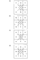
- the surrounding pixel addition unit 521 in the previous signal processing unit 52 adds pixel data located in the vicinity to each pixel data in order to improve the sensitivity of infrared light.
- the surrounding pixel adding unit 521 when the R pixel is the target pixel, the surrounding pixel adding unit 521 includes the G (Gr) positioned around the R pixel data of the target pixel. , Gb) and B pixel data of 8 pixels are added.
- red pixel data was generated from the pixel data obtained from the region corresponding to the red color filter in the light receiving element, but in the night vision mode, a wider area than in the intermediate mode.
- Pixel data for red is generated from the pixel data obtained from the above.
- pixel data obtained from an area corresponding to nine pixels including the target pixel is used for each color.
- the surrounding pixel adding unit 521 has eight R, Gb, and B pixels positioned around the pixel data of the target pixel Gr. Are added.
- the surrounding pixel adding unit 521 has eight R, Gr, and B pixels positioned around the Gb pixel data of the target pixel. Are added.
- the pixel data for green was generated from the pixel data obtained from the area corresponding to the green color filter in the light receiving element, but in the night vision mode, a wider area than in the intermediate mode.
- the pixel data for green is generated from the pixel data obtained from the above.
- the surrounding pixel adding unit 521 has R and G (Gr, Gb) positioned around the B pixel data of the target pixel.
- the pixel data of 8 pixels are added.
- blue pixel data was generated from the pixel data obtained from the region corresponding to the blue color filter in the light receiving element, but in the night vision mode, a wider area than in the intermediate mode.
- the pixel data for blue is generated from the pixel data obtained from the above.
- the surrounding pixel adding unit 521 may simply add 9 pixels of the pixel data of the target pixel and the surrounding 8 pixel pixel data, or may apply a predetermined weight to the surrounding 8 pixel pixel data. May be added to the pixel data of the pixel of interest.
- an image sensor that can read out a plurality of pixels called binning as a single pixel.
- an addition process by an image sensor having a binning function may be performed instead of the addition process by the surrounding pixel addition unit 521.
- Binning by the image sensor is substantially equivalent to addition processing by the surrounding pixel addition unit 521.
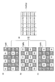
- the frames FmIR1, FmIR2, and FmIR3 are the same as the frames FmIR1, FmIR2, and FmIR3 of (a) to (c) of FIG.
- R1ad, Gr1ad, Gb1ad, B1ad, R2ad, Gr2ad, Gb2ad, B2ad, R3ad, Gr3ad, Gb3ad, and B3ad are converted to R, Gr, Gb, and B pixel data, respectively.
- the surrounding pixel addition unit 521 performs addition processing shown in FIG. 13 on the respective pixel data of the frames FmIR1, FmIR2, and FmIR3, so that the frames FmIR1ad, FmIR2ad, and FmIR3ad shown in (d) to (f) of FIG. Is generated.
- the frames FmIR1ad, FmIR2ad, and FmIR3ad are the same as the frames FmIR1ad, FmIR2ad, and FmIR3ad in (d) to (f) of FIG.
- the same-position pixel addition unit 522 adds the pixel data of R2ad and R3ad at the same pixel position in the frames FmIR2ad and FmIR3ad to the pixel data of R1ad in the frame FmIR1ad based on Expression (1).
- pixel data R123ad is generated.
- the same-position pixel addition unit 522 adds the pixel data of Gr1ad, Gb1ad, Gr3ad, and Gb3ad at the same pixel position in the frames FmIR1ad and FmIR3ad to the pixel data of Gr2ad and Gb2ad in the frame FmIR2ad based on Expression (2). Pixel data Gr123ad and Gb123ad are generated.
- the same-position pixel addition unit 522 adds the pixel data of B1ad and B2ad at the same pixel position in the frames FmIR1ad and FmIR2ad to the pixel data of B3ad in the frame FmIR3ad to generate pixel data B123ad To do.
- the combining unit 523 selects and combines the pixel data R123ad in the frame FmIR1ad, the pixel data Gr123ad and Gb123ad in the frame FmIR2ad, and the pixel data B123ad in the frame FmIR3ad. As a result, the synthesis unit 523 generates a frame FmIR123ad of the synthesized video signal shown in FIG.
- the synthesizing unit 523 generates a frame FmIR123ad in which pixel data R123ad, Gr123ad, Gb123ad, and B123ad are arranged so as to have the same arrangement as the arrangement of filter elements in the color filter 32.
- FIG. 16 shows the frame FmIR123ad.
- the demosaic processing unit 54 calculates the R pixel data at the pixel position where the R pixel data does not exist using the surrounding R pixel data, and generates the R interpolation pixel data R123adi.
- the demosaic processing unit 54 generates an R frame FmIR123adR in which all pixels in one frame shown in FIG. 16B are made up of R pixel data.
- the demosaic processing unit 54 calculates the G pixel data at the pixel position where the G pixel data does not exist using the surrounding G pixel data, and generates the G interpolation pixel data G123adi.
- the demosaic processing unit 54 generates a G frame FmIR123adG in which all the pixels in one frame shown in FIG.
- the demosaic processing unit 54 calculates the B pixel data at the pixel position where the B pixel data does not exist using the surrounding B pixel data, and generates the B interpolation pixel data B123adi.
- the demosaic processing unit 54 generates a B frame FmIR123adB in which all the pixels in one frame shown in FIG.
- the first intermediate mode and the first night-vision mode are different in that the former does not operate the surrounding pixel adding unit 521 while the latter operates the surrounding pixel adding unit 521.
- the mode switching unit 72 may operate the surrounding pixel addition unit 521 in the night vision mode.
- the operation of the demosaic processing unit 54 in the night vision mode is substantially the same as the operation of the demosaic processing unit 54 in the normal mode and the intermediate mode.
- the demosaic processing unit 54 in the video processing unit 5 and a signal processing unit such as white balance correction and gain correction can be shared.
- ⁇ Night Vision Mode: Second Night Vision Mode> The operation in the second night-vision mode will be described with reference to FIGS. In the operation in the second night vision mode, the description of the same part as the operation in the first night vision mode is omitted.
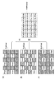
- the frames FmIR1ad, FmIR2ad, and FmIR3ad in (a) to (c) of FIG. 17 are the same as the FmIR1ad, FmIR2ad, and FmIR3ad in (a) to (c) of FIG.
- the synthesizing unit 523 selects and synthesizes R1ad that is R pixel data in the frame FmIR1ad, Gr2ad and Gb2ad that are G pixel data in the frame FmIR2ad, and B3ad that is B pixel data in the frame FmIR3ad. Thereby, the synthesis unit 523 generates a frame FmIR123′ad of the synthesized video signal shown in FIG.
- the synthesizing unit 523 generates a frame FmIR123′ad in which the pixel data R1ad, Gr2ad, Gb2ad, and B3ad are arranged so that the arrangement is the same as the arrangement of the filter elements in the color filter 32.
- the pixel data R1ad for red in the frame FmIR123'ad is obtained from a wider area than the area used for generating the pixel data for red in the intermediate mode. It is generated from pixel data.
- the pixel data Gr2ad for green in the frame FmIR123'ad is generated from pixel data obtained from an area wider than the area used for generating the pixel data for green in the intermediate mode. Yes.
- the blue pixel data B3ad in the frame FmIR123'ad is generated from pixel data obtained from an area larger than the area used to generate the blue pixel data in the intermediate mode. Yes.
- the same-position pixel addition unit 522 sets the coefficient ka in equation (1) to 1, the coefficients kb and kc to 0, and the coefficient ke in equation (2) to 1.
- the coefficients kd and kf are set to 0, the coefficient ki in the equation (3) is set to 1, and the coefficients kg and kh are set to 0.
- the pixel data of R1ad in the frame FmIR1ad, the pixel data of Gr2ad and Gb2ad in the frame FmIR2ad, and the pixel data of B3ad in the frame FmIR3ad have the same values.
- the combining unit 523 selects the pixel data of R1ad in the frame FmIR1ad, the pixel data of Gr2ad and Gb2ad in the frame FmIR2ad, and the pixel data of B3ad in the frame FmIR3ad.
- a frame FmIR123'ad can be generated.
- the demosaic processing in the demosaic processing unit 54 will be described with reference to FIG. FIG. 18A shows a frame FmIR123′ad.
- the demosaic processing unit 54 calculates the R pixel data at the pixel position where the R pixel data does not exist using the surrounding R1ad pixel data, and generates the R interpolation pixel data R1adi.
- the demosaic processing unit 54 generates an R frame FmIR123′adR in which all the pixels of one frame shown in FIG. 18B are made up of R pixel data.
- the demosaic processing unit 54 calculates the G pixel data at the pixel position where the G pixel data does not exist using the surrounding Gr2ad and Gb2ad pixel data, and generates the G interpolation pixel data G2adi.
- the demosaic processing unit 54 performs interpolation to generate a G frame FmIR123′adG in which all the pixels of one frame shown in FIG.
- the demosaic processing unit 54 generates B interpolation pixel data B3adi obtained by calculating B pixel data at a pixel position where B pixel data does not exist using surrounding B3ad pixel data.
- the demosaic processing unit 54 generates a B frame FmIR123′adB in which all the pixels in one frame shown in FIG.
- the second intermediate mode and the second night vision mode are different in that the former does not operate the surrounding pixel adding unit 521 while the latter operates the surrounding pixel adding unit 521.
- pixel data for each color is generated from each pixel data obtained from the region corresponding to each color in the light receiving element, but in the night vision mode, the surrounding pixels are added. It can also be said that pixel data for each color is generated from pixel data obtained from a region wider than each region for generating pixel data for each color.
- FIG. 19A schematically shows, as an example, how the brightness of the surrounding environment changes as time passes from the daytime period to the nighttime period.
- the brightness decreases as time elapses from daytime to evening, and it becomes almost dark after time t3.
- the brightness shown in FIG. 19A substantially indicates the amount of visible light, and there is almost no visible light after time t3.
- the control unit 7 can determine the brightness of the surrounding environment based on the luminance level of the video signal (video data) input from the video processing unit 5. As shown in FIG. 19B, the mode switching unit 72 sets the normal mode when the brightness is equal to or higher than a predetermined threshold Th1 (first threshold), and sets the predetermined threshold Th2 (less than the threshold Th1). When it is equal to or greater than the second threshold), the intermediate mode is selected.
- Th1 first threshold
- Th2 less than the threshold Th1
- the intermediate mode is selected.
- the imaging apparatus automatically selects the normal mode from time t1 until time t1 when the brightness reaches the threshold value Th1, the intermediate mode from time t1 to time t2 when the brightness reaches the threshold value Th2, and the night vision mode after time t2. Switch automatically.
- the intermediate mode may be either the first intermediate mode or the second intermediate mode
- the night vision mode may be either the first night vision mode or the second night vision mode.
- the brightness immediately before time t3 when almost no visible light is present is set as the threshold value Th2, but the brightness at time t3 may be set as the threshold value Th2.
- the mode switching unit 72 has a period of time t1 in which the visible light is relatively large in the intermediate mode period, the first intermediate mode, and a period of time t2 in which the visible light is relatively small.
- the period may be set to the second intermediate mode.
- the night-vision mode may be either the first night-vision mode or the second night-vision mode.
- the light projection control unit 71 controls on / off of the infrared projector 9, and the mode switching unit 72 switches the operation / non-operation of each unit in the video processing unit 5. Can be realized.
- the infrared projector 9 is off, the surrounding pixel adding unit 521, the same position pixel adding unit 522 and the synthesizing unit 523 are not operating, and the demosaic processing unit 54 is operating.
- the infrared projector 9 In the first intermediate mode, the infrared projector 9 is on, the surrounding pixel adding unit 521 is not operating, and the same-position pixel adding unit 522, the combining unit 523, and the demosaic processing unit 54 are operating. In the second intermediate mode, the infrared projector 9 is on, the surrounding pixel adding unit 521 and the same-position pixel adding unit 522 are not operating, and the synthesizing unit 523 and the demosaic processing unit 54 are operating.
- the operation and non-operation in the same position pixel addition unit 522 can be easily switched by appropriately setting the values of the coefficients ka to ki in the equations (1) to (3) as described above.
- the infrared projector 9 In the first night-vision mode, the infrared projector 9 is on, and the surrounding pixel adding unit 521, the same-position pixel adding unit 522, the synthesizing unit 523, and the demosaic processing unit 54 are all in an operating state. In the second night-vision mode, the infrared projector 9 is on, the same-position pixel adding unit 522 is not operating, and the surrounding pixel adding unit 521, the combining unit 523, and the demosaic processing unit 54 are operating.
- the surrounding pixel adding unit 521 sets the coefficient multiplied by the surrounding pixel data to a coefficient exceeding 0 (for example, 1) in the calculation formula for adding the surrounding pixel data to the pixel data of the target pixel.
- the surrounding pixel addition processing can be put into an operation state.
- the surrounding pixel adding unit 521 can make the surrounding pixel addition processing inoperative when the coefficient multiplied by the surrounding pixel data is set to 0 in the calculation formula.
- the operation and non-operation of the surrounding pixel addition unit 521 can be easily switched by appropriately setting the coefficient value.
- the method by which the control unit 7 detects the brightness of the surrounding environment is not limited to the method based on the luminance level of the video signal.
- the brightness sensor 11 may detect the brightness of the surrounding environment.
- the brightness of the surrounding environment may be determined based on both the luminance level of the video signal and the brightness detected by the brightness sensor 11.
- the control unit 7 does not directly detect the brightness of the surrounding environment, but roughly assumes the brightness of the surrounding environment based on the time (date) and time (time zone) in one year, and the mode switching unit 72 may be switched to each mode.
- any one of the normal mode, the intermediate mode, and the night vision mode is set corresponding to the combination of the date and the time zone.
- a clock 74 in the control unit 7 manages the date and time.
- the controller 7 reads the mode set from the mode setting table 12 with reference to the date and time indicated by the clock 74.
- the light projection control unit 71 and the mode switching unit 72 control the imaging device so that the mode read from the mode setting table 12 is set.
- the imaging device may be controlled so that the user manually selects a mode using the operation unit 13 and the projection control unit 71 and the mode switching unit 72 are in the selected mode.
- the operation unit 13 may be an operation button provided on the housing of the imaging apparatus or a remote controller.
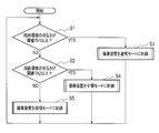
- step S1 the control unit 7 determines whether or not the brightness of the surrounding environment is equal to or greater than the threshold value Th1. If it is equal to or greater than the threshold Th1 (YES), the control unit 7 causes the process in the normal mode to be executed in step S3. If it is not greater than or equal to the threshold Th1 (NO), the control unit 7 determines whether or not the brightness of the surrounding environment is greater than or equal to the threshold Th2 in Step S2.
- control unit 7 executes processing in the intermediate mode in step S4. If it is not greater than or equal to the threshold Th2 (NO), the control unit 7 causes the process in the night-vision mode to be executed in step S5.
- the control unit 7 returns the process to step S1 after steps S3 to S5, and repeats step S1 and subsequent steps.
- FIG. 25 shows specific processing in the normal mode in step S3.
- the control part 7 (light projection control part 71) turns off the infrared light projector 9 in step S31.
- the control unit 7 inserts the infrared cut filter 21.
- the control unit 7 (mode switching unit 72) connects the switches 51 and 53 to the terminal Tb.
- the order of steps S31 to S33 is arbitrary and may be simultaneous.
- the control unit 7 causes the imaging unit 3 to image the subject in step S34.
- the control unit 7 controls the video processing unit 5 so that the demosaic processing unit 54 performs demosaic processing on the frames constituting the video signal generated by the imaging unit 3 imaging the subject.
- FIG. 26 shows specific processing in the intermediate mode in step S4.
- the control unit 7 (light projection control unit 71) turns on the infrared projector 9 so that infrared light of wavelengths IR1 to IR3 is projected in a time-sharing manner from the light projecting units 91 to 93.
- the control unit 7 inserts the dummy glass 22 in step S42.
- the control unit 7 (mode switching unit 72) connects the switches 51 and 53 to the terminal Ta.
- the order of steps S41 to S43 is arbitrary and may be simultaneous.
- the control unit 7 causes the imaging unit 3 to image the subject in step S44.
- the imaging unit 3 projects infrared light with a wavelength IR1 associated with R, infrared light with a wavelength IR2 associated with G, and infrared light with a wavelength IR3 associated with B, respectively. Take a picture of the subject in the
- step S45 the control unit 7 (mode switching unit 72) controls the pre-signal processing unit 52 so that the surrounding pixel addition unit 521 is deactivated and the synthesis unit 523 is operated to generate a synthesized video signal.
- the frames constituting the video signal generated when the imaging unit 3 images the subject in the state where infrared light of wavelengths IR1, IR2, and IR3 are respectively projected are the first frame, the second frame, 3 frames are assumed.
- the synthesizing unit 523 converts the three primary color pixel data based on the R pixel data in the first frame, the G pixel data in the second frame, and the B pixel data in the third frame into color
- the filters 32 are arranged so as to have the same arrangement as the filter elements.
- the combining unit 523 generates a combined video signal by combining the first to third frames into one frame in this way.
- step S46 the control unit 7 controls the video processing unit 5 so that the demosaic processing unit 54 performs demosaic processing on the frame of the composite video signal.
- the demosaic processing unit 54 performs demosaic processing for generating an R frame, a G frame, and a B frame based on the frame of the composite video signal, and sequentially generates the demosaiced three primary color frames. .
- the demosaic processing unit 54 can generate an R frame by interpolating the R pixel data at a pixel position where the R pixel data does not exist.
- the demosaic processing unit 54 can generate the G frame by interpolating the G pixel data at the pixel position where the G pixel data does not exist.
- the demosaic processing unit 54 can generate the B frame by interpolating the B pixel data at the pixel position where the B pixel data does not exist.
- step S45 the same position pixel addition unit 522 is operated in step S45, and in the case of the second intermediate mode, the same position pixel addition unit 522 is not operated in step S45. do it.
- FIG. 27 shows specific processing in the night-vision mode in step S5.
- the control unit 7 (light projection control unit 71) turns on the infrared projector 9 so that infrared light of wavelengths IR1 to IR3 is projected in a time-sharing manner from the light projecting units 91 to 93.
- the control unit 7 inserts the dummy glass 22 in step S52.
- the control unit 7 (mode switching unit 72) connects the switches 51 and 53 to the terminal Ta.
- the order of steps S51 to S53 is arbitrary and may be simultaneous.
- the control unit 7 causes the imaging unit 3 to image the subject in step S54.
- the control unit 7 (mode switching unit 72) controls the previous signal processing unit 52 to operate the surrounding pixel addition unit 521 and the synthesis unit 523 to generate a synthesized video signal.
- step S56 the control unit 7 controls the video processing unit 5 so that the demosaic processing unit 54 performs demosaic processing on the frame of the composite video signal.
- step S55 the same position pixel addition unit 522 is operated in step S55, and in the case of the second night vision mode, the same position pixel addition unit 522 is disabled in step S55. It may be an operation.
- control unit 7 or the video processing unit 5 and the control unit 7 are integrated by a computer (microcomputer), and the video signal processing program (computer program) is executed by the computer. It is also possible to realize the same operation as that of the imaging apparatus of this embodiment.
- FIG. 28 shows processing that the video signal processing program causes the computer to execute.
- step S401 the video signal processing program controls the infrared projector 9 so as to project infrared light of wavelengths IR1, IR2, and IR3 associated with R, G, and B to the computer. To execute the process.
- step S401 may be executed outside the video signal processing program.
- the step of inserting the dummy glass 22 is omitted.
- the step of inserting the dummy glass 22 may also be executed outside the video signal processing program.
- step S402 the video signal processing program captures the first frame of the video signal generated by the imaging unit 3 imaging the subject in a state where infrared light having the wavelength IR1 is projected on the computer.
- a process of acquiring pixel data to be configured is executed.
- step S403 the video signal processing program captures the second frame of the video signal generated when the imaging unit 3 images the subject in a state where infrared light having the wavelength IR2 is projected on the computer.
- a process of acquiring pixel data to be configured is executed.
- step S404 the video signal processing program captures a third frame of the video signal generated when the imaging unit 3 images the subject in a state where infrared light having the wavelength IR3 is projected on the computer.
- a process of acquiring pixel data to be configured is executed. The order of steps S402 to S404 is arbitrary.
- step S405 the video signal processing program causes the computer to arrange the R, G, and B pixel data so as to be in the same arrangement as the arrangement of the filter elements in the color filter 32, and synthesize the synthesized video into one frame.
- a process for generating a signal is executed.
- the video signal processing program does not cause the computer to execute the process of adding the surrounding pixels in step S405.
- step S406 the video signal processing program causes the computer to perform a process of generating a R, G, B frame by performing a demosaic process on the frame of the composite video signal.
- step S5 in FIG. 24 when the control in the night vision mode, which is step S5 in FIG. 24, is configured by the video signal processing program, the processing of adding peripheral pixels is executed in the computer in step S405 in FIG. You can do it.
- the video signal processing program may be a computer program recorded on a computer-readable recording medium.
- the video signal processing program may be provided in a state where it is recorded on a recording medium, or may be provided via a network such as the Internet so that the computer can download the video signal processing program.
- the computer-readable recording medium may be any non-temporary arbitrary recording medium such as a CD-ROM or a DVD-ROM.
- FIG. 29 schematically shows a control method of the image pickup apparatus when a frame of a video signal is generated by the image pickup apparatus without particularly considering reduction of color misregistration.
- FIG. 29 (a) is equivalent to FIG. 8 (a), and shows a state of infrared light projection by the infrared projector 9.
- FIG. Here, a case is shown in which infrared light of wavelengths IR1 to IR3 is projected for a period shorter than one frame period, not the entire one exposure period of the maximum exposure time in the imaging unit 3.
- exposures Ex1R, Ex1G, Ex1B, Ex2R, Ex2G, Ex2B,... are performed at the timing of projecting infrared light of wavelengths IR1 to IR3.
- FIG. 29 (c) shows a frame F of an image captured by the exposure shown in FIG. 29 (b).
- the frame F imaged by the exposures Ex1R, Ex1G, and Ex1B is shown.
- the rectangular object OB is moving in the horizontal direction from left to right at a speed v.
- frames F1IR1, F1IR2, and F1IR3 are obtained based on the exposures Ex1R, Ex1G, and Ex1B.
- Frames F2IR1, F2IR2, and F2IR3 are obtained based on the exposures Ex2R, Ex2G, and Ex2B.
- Frames F3IR1, F3IR2, and F3IR3 are obtained based on the exposures Ex3R, Ex3G, and Ex3B.
- the frame frequency of the imaging signal shown in (b) of FIG. 29 and the frame frequency of the frame shown in (d) of FIG. 29 are 90 frames / second.
- the frame frequency is 30 frames / second for the entire exposure Ex1R, Ex1G, Ex1B, the entire exposure Ex2R, Ex2G, Ex2B, and the entire exposure Ex3R, Ex3G, Ex3B.
- the frame F1IR is generated by combining the frames F1IR1, F1IR2, and F1IR3, and the frame F2IR is generated by combining the frames F2IR1, F2IR2, and F2IR3.
- the frames F1IR and F2IR have a frame frequency of 30 frames / second.
- the central timing of the period during which infrared light of wavelengths IR1 to IR3 is projected is set to the central timing of one frame period which is the maximum exposure time. Match.
- the object OB in the frame F1IR1 is expressed in red or a color similar to red.
- the object OB in the frame F1IR2 is expressed in green or a color similar to green.
- the object OB in the frame F1IR3 is expressed in blue or a color similar to blue.
- each color may not be expressed depending on the material of the object OB.
- the object OB of the frame F1IR1 is expressed in red
- the object OB of the frame F1IR2 is expressed in green
- the object OB of the frame F1IR3 is expressed in blue.
- the central timing interval of each maximum exposure time is defined as time t0.
- a yellow color shift region C2 is generated by overlapping the red object OB of the frame F1IR1 and the green object OB of the frame F1IR2 adjacent to the color shift region C1. Strictly speaking, yellow color misregistration may not occur, but for convenience of explanation, it is assumed that yellow color misregistration occurs.
- an area C3 in which a correct color is expressed is generated by overlapping the object OB of the frame F1IR1, the object OB of the frame F1IR2, and the object OB of the frame F1IR3, all adjacent to the color misregistration area C2.
- a cyan color misregistration region C4 is generated by overlapping the green object OB of the frame F1IR2 and the blue object OB of the frame F1IR3 adjacent to the region C3. Strictly speaking, cyan color misregistration may not occur. However, for convenience of explanation, it is assumed that cyan color misregistration occurs.
- color misregistration regions C1, C2, C4, and C5 are generated around the region C3 where the correct color is expressed, thereby degrading the image quality.
- FIGS. 30 to 32 it is preferable to use a method for controlling the imaging apparatus as shown in FIGS. 30 to 32 in order to reduce color misregistration.
- the control method of FIGS. 30 to 32 will be described in order.
- the exposure start timing of exposure Ex1R is ExRs
- the exposure end timing is ExRe
- the exposure start timing of exposure Ex1G is ExGs
- the exposure end timing is ExGe
- the exposure start timing of exposure Ex1B is ExBs
- the central timing of the period during which infrared light of wavelength IR1 is projected within the period of exposure Ex1R is the maximum exposure time of exposure Ex1R. It is shifted to the exposure end timing ExRe side behind the center timing.
- the timing of the center of the period in which infrared light of wavelength IR3 is projected within the period of exposure Ex1B is shifted to the exposure start timing ExBs side ahead of the center timing of the maximum exposure time of exposure Ex1B.
- the central timing of the period in which infrared light of wavelength IR2 is projected is made to coincide with the central timing of the maximum exposure time of the exposure Ex1G, as in FIG.
- the central timing of the period for projecting infrared light of wavelength IR2 does not necessarily coincide with the central timing of the maximum exposure time of exposure Ex1G. However, it is preferable that the central timing of the period for projecting the infrared light with the wavelength IR2 coincides with the central timing of the maximum exposure time of the exposure Ex1G.
- the interval between the central timing of projecting infrared light with wavelength IR2 and the central timing of projecting infrared light with wavelength IR1 is defined as time t1.
- the interval between the central timing of the period for projecting infrared light of wavelength IR2 and the central timing of the period of projecting infrared light of wavelength IR3 is defined as time t1.
- the center timing of the period for projecting infrared light of wavelength IR1 is shifted to the exposure end timing ExRe side, and the center timing of the period for projecting infrared light of wavelength IR3 is set to the exposure start timing ExBs. It is shifted to the side.
- the color misregistration regions C1 and C2 can be shortened.
- the color misregistration regions C4 and C5 can be shortened.
- the interval between the central timing of the infrared light projection period located at the center and the central timing of the infrared light projection period positioned before or after is set at the center. It is shorter than the interval between the central timing of the infrared light projection period and the central timing of the maximum exposure times of the exposures Ex1R and Ex1B. Therefore, according to the first example, color misregistration can be reduced.
- the configuration of the imaging apparatus that employs the control method of the first example is summarized as follows.
- the first infrared light has a first wavelength associated with a first color of red, green, and blue.
- the second infrared light has a second wavelength associated with a second color of red, green, and blue.
- the third infrared light has a third wavelength associated with a third color of red, green, and blue.
- the light projection control unit 71 controls the infrared projector 9 so as to selectively project the infrared light in the order of the first infrared light, the second infrared light, and the third infrared light.
- the imaging unit 3 captures the subject in a state where the first infrared light is projected in at least a part of one frame period, and generates a first frame based on the first imaging signal.
- One frame period is determined by the maximum exposure time of the imaging unit 3.
- the imaging unit 3 images the subject in a state where the second infrared light is projected in at least a part of one frame period, and generates a second frame based on the second imaging signal.
- the imaging unit 3 images the subject in a state where the third infrared light is projected in at least a part of one frame period, and generates a third frame based on the third imaging signal.
- the video processing unit 5 combines the first to third frames to generate a video signal frame.
- the central timing of the period during which the second infrared light is projected is the first timing.
- the central timing of the period during which the first or third infrared light is projected is set as the second timing.
- the center timing of one frame period of the first or third frame is set as the third timing.
- the light projection control unit 71 sets the interval between the first timing and the second timing to be shorter than the interval between the first timing and the third timing, and outputs the first to third infrared lights.
- the infrared projector 9 is controlled to project light.
- the center timing of one frame period of the second frame is the fourth timing. More preferably, the light projection control unit 71 controls the infrared projector 9 to project the second infrared light by matching the first timing with the fourth timing.
- the operation of the imaging apparatus adopting the control method of the first example may be realized by causing a computer to execute a control program (computer program) of the imaging apparatus.
- a control program computer program
- the control program for the imaging apparatus may be a computer program recorded on a computer-readable non-transitory recording medium.
- control program of the imaging apparatus executes a first step for controlling the infrared projector 9 to cause the computer to project the first infrared light, and a second step for generating the first frame.
- the control program for the imaging apparatus causes the computer to execute a third step for controlling the infrared projector 9 to project the second infrared light and a fourth step for generating the second frame.
- the control program for the image pickup apparatus includes a fifth step for controlling the infrared projector 9 to cause the computer to emit third infrared light, a sixth step for generating a third frame, and first to third steps.
- a seventh step of synthesizing the frames to generate a frame of the video signal is executed.
- the control program of the imaging apparatus sets the interval between the first timing and the second timing to be shorter than the interval between the first timing and the third timing.
- FIG. 31 Next, the second example shown in FIG. 31 will be described focusing on the differences from the first example of FIG. (A), (c) to (g) in FIG. 31 correspond to (a) to (f) in FIG. 30, respectively.
- the periods for projecting infrared light with wavelengths IR1 to IR3 are set as exposures Ex1R, Ex1G, Ex1B, Ex2R, Ex2G, Ex2B, Ex3R, Ex3G, It is almost the whole of one frame period of Ex3B,.
- FIG. 31B shows a period and timing when the electronic shutter of the imaging unit 3 controlled by the electronic shutter control unit 73 is opened.
- the central timing of the electronic shutter opening period St12 is made to coincide with the central timing of the maximum exposure time.
- the central timing of the electronic shutter open period St11 is shifted to the exposure end timing ExRe side behind the central timing of the maximum exposure time of exposure Ex1R.
- the central timing of the electronic shutter opening period St13 is shifted to the exposure start timing ExBs side ahead of the central timing of the maximum exposure time of exposure Ex1B.
- the state of the region C3 and the color misregistration regions C1, C2, C4, and C5 in which the correct color of the frame F1IR shown in (g) of FIG. 31 is expressed is shown in (f) of FIG. The same as the frame F1IR. Also in the second example, color misregistration can be reduced.
- FIG. 32 will be described focusing on differences from the first example of FIG. 30 and the second example of FIG. (A) to (g) in FIG. 32 correspond to (a) to (g) in FIG. 31, respectively.
- the period for projecting infrared light with wavelengths IR1 to IR3 and the open period of the electronic shutter are matched.
- the period and timing for projecting infrared light of wavelengths IR1 to IR3 in the third example are the same as those in the first example of FIG.
- the open period of the electronic shutter is set at the same timing as the infrared light projection period with respect to the first example. Also in the third example, color misregistration can be reduced.
- the configuration of the imaging apparatus that employs the control method of the second or third example is summarized as follows, focusing on differences from the configuration of the imaging apparatus that employs the control method of the first example.
- the electronic shutter control unit 73 controls the function of the electronic shutter in the imaging unit 3.
- the timing at the center of the period during which the imaging unit 3 is exposed in the state where the second infrared light is projected is defined as the first timing.
- the timing at the center of the period during which the imaging unit 3 is exposed in the state where the first or third infrared light is projected is set as the second timing.
- the center timing of one frame period of the first or third frame is set as the third timing.
- the electronic shutter control unit 73 sets a period and timing for exposing the imaging unit 3 so that the interval between the first timing and the second timing is set to be shorter than the interval between the first timing and the third timing. To control.
- the operation of the imaging apparatus employing the control method of the above second or third example may be realized by causing a computer to execute a control program (computer program) of the imaging apparatus.
- the control program for the imaging apparatus sets the interval between the first timing and the second timing to be shorter than the interval between the first timing and the third timing by the electronic shutter function in the imaging unit 3 in the computer.
- a process for controlling the period and timing for exposing the imaging unit 3 may be executed.
- control unit 7 and the video processing unit 5 can be realized using one or a plurality of hardware (circuits or processors). Use of hardware and software is optional.
- the imaging device may be configured only by hardware, or a part of the configuration may be realized by software.
- the imaging apparatus, the imaging apparatus control method, and the control program according to the present invention can be used for a monitoring camera that monitors a subject in an environment with little visible light.
Landscapes
- Engineering & Computer Science (AREA)
- Multimedia (AREA)
- Signal Processing (AREA)
- Physics & Mathematics (AREA)
- Spectroscopy & Molecular Physics (AREA)
- Color Television Image Signal Generators (AREA)
- Studio Devices (AREA)
- Transforming Light Signals Into Electric Signals (AREA)
Abstract
投光制御部(71)は、第1の赤外光、第2の赤外光、第3の赤外光の順で赤外光を選択的に投光するよう赤外線投光器(9)を制御する。撮像部(3)は、第1~第3の赤外光がそれぞれ投光されている状態で被写体を撮像して、第1~第3のフレームを生成する。映像処理部(5)は、第1~第3のフレームを合成して、映像信号のフレームを生成する。投光制御部(71)は、第2の赤外光を投光する期間の中央の第1のタイミングと、第1または第3の赤外光を投光する期間の中央の第2のタイミングとの間隔を、第1のタイミングと、第1または第3のフレームの1フレーム期間の中央の第3のタイミングとの間隔よりも短く設定する。
Description
本開示は、撮像装置、撮像装置の制御方法及び制御プログラムに関する。
従来、例えば夜間等の可視光がほとんどない環境下において被写体を撮像するために、赤外線投光器によって被写体に赤外光を照射し、被写体から反射した赤外光を撮像する方法が用いられている。この方法は、可視光を照射するライトを用いることができない場合に有効な撮像方法である。
しかしながら、この撮像方法によって被写体を撮像した映像は、モノクロ映像となる。モノクロ映像では物体の識別が困難となることがある。可視光がない環境下でもカラー映像を撮像することができれば、物体の識別性を向上させることができる。例えば監視カメラでは、物体の識別性を向上させるために、可視光がない環境下でもカラー映像を撮像することが望まれる。
特許文献1には、可視光がない環境下でもカラー映像を撮像することができる撮像装置が記載されている。特許文献1に記載されている撮像装置においても、赤外線投光器が用いられる。監視カメラに特許文献1に記載の技術を搭載すれば、被写体をカラー映像化して物体の識別性を向上させることが可能となる。
赤外線投光器を備える撮像装置によって被写体に赤外光を照射して被写体を撮像するとき、被写体が動いている場合には、色ずれが発生するという問題点がある。
実施形態は、動いている被写体に赤外光を照射して被写体を撮像するときに発生する色ずれを軽減させることができる撮像装置、撮像装置の制御方法及び制御プログラムを提供することを目的とする。
実施形態の第1の態様によれば、赤外線投光器によって、赤色と緑色と青色のうちの第1の色に対応付けられた第1の波長を有する第1の赤外光と、赤色と緑色と青色のうちの第2の色に対応付けられた第2の波長を有する第2の赤外光と、赤色と緑色と青色のうちの第3の色に対応付けられた第3の波長を有する第3の赤外光とをこの順で選択的に投光するよう、前記赤外線投光器を制御する投光制御部と、前記第1の赤外光が1フレーム期間の少なくとも一部で投光されている状態で被写体を撮像して、第1の撮像信号に基づく第1のフレームを生成し、前記第2の赤外光が1フレーム期間の少なくとも一部で投光されている状態で前記被写体を撮像して、第2の撮像信号に基づく第2のフレームを生成し、前記第3の赤外光が1フレーム期間の少なくとも一部で投光されている状態で前記被写体を撮像して、第3の撮像信号に基づく第3のフレームを生成する撮像部と、前記第1~第3のフレームを合成して、映像信号のフレームを生成する映像処理部とを備え、前記投光制御部は、前記第2の赤外光を投光する期間の中央である第1のタイミングと、前記第1または第3の赤外光を投光する期間の中央である第2のタイミングとの間隔を、前記第1のタイミングと、前記第1または第3のフレームの1フレーム期間の中央である第3のタイミングとの間隔よりも短く設定して、前記第1~第3の赤外光を投光するよう前記赤外線投光器を制御することを特徴とする撮像装置が提供される。
実施形態の第2の態様によれば、赤色と緑色と青色のうちの第1の色に対応付けられた第1の波長を有する第1の赤外光が1フレーム期間の少なくとも一部で投光されている状態で被写体を撮像して、第1の撮像信号に基づく第1のフレームを生成する第1のステップと、前記第1のステップに続き、赤色と緑色と青色のうちの第2の色に対応付けられた第2の波長を有する第2の赤外光が1フレーム期間の少なくとも一部で投光されている状態で前記被写体を撮像して、第2の撮像信号に基づく第2のフレームを生成する第2のステップと、前記第2のステップに続き、赤色と緑色と青色のうちの第3の色に対応付けられた第3の波長を有する第3の赤外光が1フレーム期間の少なくとも一部で投光されている状態で前記被写体を撮像して、第3の撮像信号に基づく第3のフレームを生成する第3のステップと、前記第1~第3のフレームを合成して、映像信号のフレームを生成する第4のステップとを含み、前記第2の赤外光を投光する期間の中央である第1のタイミングと、前記第1または第3の赤外光を投光する期間の中央である第2のタイミングとの間隔を、前記第1のタイミングと、前記第1または第3のフレームの1フレーム期間の中央である第3のタイミングとの間隔よりも短く設定することを特徴とする撮像装置の制御方法が提供される。
実施形態の第3の態様によれば、コンピュータに、赤色と緑色と青色のうちの第1の色に対応付けられた第1の波長を有する第1の赤外光を投光させるよう、赤外線投光器を制御する第1のステップと、前記第1の赤外光が1フレーム期間の少なくとも一部で投光されている状態で、撮像部によって被写体を撮像させて、第1の撮像信号に基づく第1のフレームを生成する第2のステップと、前記第1のステップに続き、赤色と緑色と青色のうちの第2の色に対応付けられた第2の波長を有する第2の赤外光を投光させるよう、前記赤外線投光器を制御する第3のステップと、前記第2の赤外光が1フレーム期間の少なくとも一部で投光されている状態で、前記撮像部によって前記被写体を撮像させて、第2の撮像信号に基づく第2のフレームを生成する第4のステップと、前記第3のステップに続き、赤色と緑色と青色のうちの第3の色に対応付けられた第3の波長を有する第3の赤外光を投光させるよう、前記赤外線投光器を制御する第5のステップと、前記第3の赤外光が1フレーム期間の少なくとも一部で投光されている状態で、前記撮像部によって前記被写体を撮像させて、第3の撮像信号に基づく第3のフレームを生成する第6のステップと、前記第1~第3のフレームを合成して、映像信号のフレームを生成する第7のステップとを実行させ、前記第2の赤外光を投光する期間の中央である第1のタイミングと、前記第1または第3の赤外光を投光する期間の中央である第2のタイミングとの間隔を、前記第1のタイミングと、前記第1または第3のフレームの1フレーム期間の中央である第3のタイミングとの間隔よりも短く設定することを特徴とする撮像装置の制御プログラムが提供される。
実施形態の撮像装置、撮像装置の制御方法及び制御プログラムによれば、動いている被写体に赤外光を照射して被写体を撮像するときに発生する色ずれを軽減させることができる。
以下、一実施形態の撮像装置、撮像装置の制御方法及び制御プログラムについて、添付図面を参照して説明する。
<撮像装置の構成>
まず、図1を用いて、一実施形態の撮像装置の全体的な構成について説明する。図1に示す一実施形態の撮像装置は、昼間等の可視光が十分に存在する環境下に適した通常モードと、夜間等の可視光がほとんどない環境下に適した暗視モードと、可視光がわずかに存在する環境下に適した中間モードとの3つのモードで撮像可能な撮像装置である。
まず、図1を用いて、一実施形態の撮像装置の全体的な構成について説明する。図1に示す一実施形態の撮像装置は、昼間等の可視光が十分に存在する環境下に適した通常モードと、夜間等の可視光がほとんどない環境下に適した暗視モードと、可視光がわずかに存在する環境下に適した中間モードとの3つのモードで撮像可能な撮像装置である。
中間モードは、可視光が少ない環境下で、赤外線を投光しながら撮像する第1の赤外光投光モードである。暗視モードは、可視光がさらに少ない(ほとんどない)環境下で、赤外線を投光しながら撮像する第2の赤外光投光モードである。
撮像装置は、中間モードと暗視モードとのうちの一方のみを備えていてもよい。撮像装置は、通常モードを備えていなくてもよい。撮像装置は、少なくとも、赤外線を投光しながら撮像する赤外光投光モードを備えていればよい。
図1において、被写体から反射した一点鎖線にて示す光は、光学レンズ1によって集光される。ここで、光学レンズ1には、可視光が十分に存在する環境下では可視光、可視光がほとんどない環境下では後述する赤外線投光器9より発せられた赤外光を被写体が反射した赤外光が入射される。
可視光がわずかに存在する環境下では、光学レンズ1には、可視光と赤外線投光器9より発せられた赤外光を被写体が反射した赤外光とが混在した光が入射される。
図1では簡略化のため、光学レンズ1を1つのみとしているが、実際には、撮像装置は複数の光学レンズを備える。
光学レンズ1と撮像部3との間には、光学フィルタ2が設けられている。光学フィルタ2は、赤外線カットフィルタ21とダミーガラス22との2つの部分を有する。光学フィルタ2は、駆動部8によって、光学レンズ1と撮像部3との間に赤外線カットフィルタ21を挿入した状態と、光学レンズ1と撮像部3との間にダミーガラス22を挿入した状態とのいずれかの状態に駆動される。
撮像部3は、水平方向及び垂直方向に複数の受光素子(画素)が配列した撮像素子31と、それぞれの受光素子に対応して赤色(R),緑色(G),青色(B)のいずれかの色のフィルタエレメントが配置されたカラーフィルタ32とを有する。撮像素子31は、CCD(Charge Coupled Device)またはCMOS(Complementary Metal Oxide Semiconductor)でよい。
カラーフィルタ32には、一例として、図2に示すように、R,G,Bの各色のフィルタエレメントがベイヤ配列と称される配列で並べられている。ベイヤ配列は、R,G,Bのフィルタエレメントの所定の配列の一例である。図2において、各行のRのフィルタエレメントに挟まれたGのフィルタエレメントをGr、Bのフィルタエレメントに挟まれたGのフィルタエレメントをGbとしている。
ベイヤ配列では、RのフィルタエレメントとGrのフィルタエレメントとが交互に配置された水平方向の行と、BのフィルタエレメントとGbのフィルタエレメントとが交互に配置された水平方向の行とが、垂直方向に交互に配列されている。
図3は、撮像部3におけるR光,G光,B光の波長と相対感度との分光感度特性を示している。相対感度は、最大値が1に正規化されている。撮像装置を通常モードで動作させるとき、可視光による良好なカラー映像を撮像するには、波長700nm以上の赤外光をカットする必要がある。
そこで、駆動部8は、制御部7による制御に基づいて、光学レンズ1と撮像部3との間に赤外線カットフィルタ21を挿入するように光学フィルタ2を駆動する。
図3より分かるように、撮像部3は、波長700nm以上の赤外光の領域においても感度を有する。そこで、撮像装置を中間モードまたは暗視モードで動作させるときには、駆動部8は、制御部7による制御に基づいて、光学レンズ1と撮像部3との間の赤外線カットフィルタ21を外してダミーガラス22を挿入するように光学フィルタ2を駆動する。
光学レンズ1と撮像部3との間にダミーガラス22を挿入した状態では、波長700nm以上の赤外光はカットされない。よって、撮像装置は、図3に破線の楕円で囲んだ部分の感度を利用して、R,G,Bの各色情報を得ることが可能となる。ダミーガラス22を挿入するのは、光路長を、赤外線カットフィルタ21を挿入した場合の光路長と同じにするためである。
赤外線投光器9は、それぞれ、波長IR1,IR2,IR3の赤外光を投光する投光部91,92,93を有する。中間モードまたは暗視モードのとき、制御部7内の投光制御部71は、時分割で投光部91~93より波長IR1~IR3の赤外光を選択的に投光させるように制御する。
ところで、撮像素子31にはシリコンウェハが用いられている。図4は、R,G,Bそれぞれの色を呈する素材に白色光を照射した場合の各波長における反射率にシリコンの受光感度を乗じたときの、波長と相対検出率との関係を示している。図4においても、相対検出率は、最大値が1に正規化されている。
図4に示すように、赤外光の領域において、例えば、波長780nmにおける反射光はR色を呈する素材の反射光との相関性が高く、波長870nmにおける反射光はB色を呈する素材の反射光との相関性が高く、波長940nmにおける反射光はG色を呈する素材の反射光との相関性が高い。
そこで、本実施形態においては、投光部91,92,93が投光する赤外光の波長IR1,IR2,IR3を、780nm,940nm,870nmとする。これらの波長は、波長IR1~IR3の一例であり、780nm,940nm,870nm以外でもよい。
投光部91が波長IR1の赤外光を被写体に照射し、被写体から反射した光を撮像した映像信号をR信号に割り当てる。投光部93が波長IR2の赤外光を被写体に照射し、被写体から反射した光を撮像した映像信号をG信号に割り当てる。投光部92が波長IR3の赤外光を被写体に照射し、被写体から反射した光を撮像した映像信号をB信号に割り当てる。
このようにすれば、原理的に、中間モードまたは暗視モードにおいても、通常モードにおいて可視光が存在する環境下で被写体を撮像した場合と同様の色を再現することができる。
色味が被写体の実際の色味と異なるカラー映像となるものの、780nmの波長IR1をR光、870nmの波長IR3をG光、940nmの波長IR2をB光に割り当ててもよい。波長IR1,IR2,IR3をR光,G光,B光に任意に割り当てることも可能である。
本実施形態においては、被写体の色味を最もよく再現する、波長IR1,IR2,IR3をそれぞれR光,G光,B光に割り当てることとする。
制御部7は、撮像部3における撮像と、映像処理部5内の各部を制御する。制御部7内の電子シャッタ制御部73は、撮像部3における電子シャッタの機能を制御する。撮像部3によって撮像された映像信号はA/D変換器4によってA/D変換され、映像処理部5に入力される。撮像部3とA/D変換器4とが一体化されていてもよい。
制御部7は、通常モードと中間モードと暗視モードとを切り換えるモード切換部72を備える。モード切換部72は、通常モードと中間モードと暗視モードとに対応させて、映像処理部5内の動作を後述のように適宜切り換える。映像処理部5と制御部7とが一体化されていてもよい。
映像処理部5は、スイッチ51,53と、前信号処理部52と、デモザイク処理部54とを有する。スイッチ51,53は物理的なスイッチであってもよく、前信号処理部52の動作と不動作とを切り換えるための概念的なスイッチであってもよい。制御部7には、撮像している映像の明るさを検出するために、映像処理部5から映像信号が入力される。
図5に示すように、前信号処理部52は、周囲画素加算部521と、同一位置画素加算部522と、合成部523とを有する。
映像処理部5は、R,G,Bの3原色データを生成して、映像出力部6に供給する。映像出力部6は、3原色データを所定の形式で図示していない表示部等へと出力する。
映像出力部6は、R,G,B信号をそのまま出力してもよいし、R,G,B信号を輝度信号と色信号(または色差信号)に変換して出力してもよい。映像出力部6は、コンポジット映像信号を出力してもよい。映像出力部6は、デジタル信号の映像信号を出力してもよいし、D/A変換器によってアナログ信号に変換した映像信号を出力してもよい。
以下、通常モードと中間モードと暗視モードとのそれぞれの具体的な動作について説明する。
<通常モード>
通常モードでは、制御部7は、駆動部8によって、光学レンズ1と撮像部3との間に赤外線カットフィルタ21を挿入させる。投光制御部71は、赤外線投光器9による赤外光の投光をオフにする。
通常モードでは、制御部7は、駆動部8によって、光学レンズ1と撮像部3との間に赤外線カットフィルタ21を挿入させる。投光制御部71は、赤外線投光器9による赤外光の投光をオフにする。
撮像部3によって撮像された映像信号は、A/D変換器4によってデジタル信号である映像データに変換されて、映像処理部5に入力される。通常モードでは、モード切換部72は、スイッチ51,53を端子Tbに接続するように制御する。
図6の(a)は、撮像部3の露光Ex1,Ex2,Ex3…を示している。実際には露光時間はシャッタスピード等の条件によって変化するが、ここでは露光Ex1,Ex2,Ex3は最大露光時間を示している。なお、シャッタスピードは電子シャッタ制御部73におる制御によって決定される。
図6の(b)は、それぞれの映像信号のフレームが得られるタイミングを示している。露光Ex1の前の図示していない露光に基づいて、所定時間後に映像信号のフレームF0が得られる。露光Ex1に基づいて、所定時間後に映像信号のフレームF1が得られる。露光Ex2に基づいて、所定時間後に映像信号のフレームF2が得られる。露光Ex3以降も同様である。映像信号のフレーム周波数を、例えば30フレーム/秒とする。
映像信号のフレーム周波数は、NTSC方式であれば30フレーム/秒または60フレーム/秒、PAL方式であれば25フレーム/秒または50フレーム/秒のように適宜設定すればよい。また、映像信号のフレーム周波数は、映画で使われている24フレーム/秒であってもよい。
A/D変換器4より出力された各フレームの映像データは、スイッチ51,53を介してデモザイク処理部54に入力される。デモザイク処理部54は、入力された各フレームの映像データにデモザイク処理を施す。映像処理部5は、デモザイク処理の他、ホワイトバランス補正やゲイン補正等の各種の映像処理を施して、R,G,Bの3原色データを出力する。
図7を用いて、デモザイク処理部54におけるデモザイク処理について説明する。図7において、(a)は映像データの任意のフレームFmを示している。フレームFmは、有効映像期間の画素によって構成されたフレームである。映像データの画素数は、例えばVGA規格では水平640画素、垂直480画素である。ここでは簡略化のため、フレームFmの画素数を大幅に少なくして、フレームFmを概念的に示している。
ベイヤ配列の撮像部3を用いて生成された映像データは、フレームFm内で、R,G,Bの画素データが混在したデータである。デモザイク処理部54は、Rの画素データが存在しない画素位置のRの画素データを周囲のRの画素データを用いて算出したRの補間画素データRiを生成する。デモザイク処理部54は、図7の(b)に示す1フレームの全画素がRの画素データよりなるRフレームFmRを生成する。
デモザイク処理部54は、Gの画素データが存在しない画素位置のGの画素データを周囲のGの画素データを用いて算出したGの補間画素データGiを生成する。デモザイク処理部54は、図7の(c)に示す1フレームの全画素がGの画素データよりなるGフレームFmGを生成する。
デモザイク処理部54は、Bの画素データが存在しない画素位置のBの画素データを周囲のBの画素データを用いて算出したBの補間画素データBiを生成する。デモザイク処理部54は、図7の(d)に示す1フレームの全画素がBの画素データよりなるBフレームFmBを生成する。
デモザイク処理部54は、Rの画素データを補間する際には少なくともRの画素データを用いればよく、Gの画素データを補間する際には少なくともGの画素データを用いればよく、Bの画素データを補間する際には少なくともBの画素データを用いればよい。デモザイク処理部54は、補間精度を向上させるために、R,G,Bの画素データを補間する際に、生成しようとする補間画素データの色とは異なる他の色の画素データを用いてもよい。
撮像部3には、有効映像期間より外側の画素も存在しているため、フレームFmの上下左右端部に位置する画素においても、R,G,Bの画素データを補間することができる。
デモザイク処理部54によって生成されたRフレームFmR,GフレームFmG,BフレームFmBがR,G,Bの3原色データとして出力される。図6では、理解を容易にするため、R,G,Bの画素データをフレーム単位で説明したが、実際には、R,G,Bの画素データは画素ごとに順次出力される。
<中間モード:第1中間モード>
中間モード(第1中間モード及び後述する第2中間モード)では、制御部7は、駆動部8によって、光学レンズ1と撮像部3との間にダミーガラス22を挿入させる。投光制御部71は、赤外線投光器9による赤外光の投光をオンにする。モード切換部72は、スイッチ51,53を端子Taに接続するように制御する。
中間モード(第1中間モード及び後述する第2中間モード)では、制御部7は、駆動部8によって、光学レンズ1と撮像部3との間にダミーガラス22を挿入させる。投光制御部71は、赤外線投光器9による赤外光の投光をオンにする。モード切換部72は、スイッチ51,53を端子Taに接続するように制御する。
図8の(a)は、赤外線投光器9による赤外光の投光の状態を示している。制御部7は、通常モードの1フレーム期間を1/3ずつに分け、例えば投光部91,92,93の順に赤外光を投光させるように制御する。
図8の(a)に示す例では、1フレームの最初の1/3の期間では、波長IR1(780nm)の赤外光が被写体に照射される。1フレームの次の1/3の期間では、波長IR2(940nm)の赤外光が被写体に照射される。1フレームの最後の1/3の期間では、波長IR3(870nm)の赤外光が被写体に照射される。波長IR1~IR3の赤外光を投光する順番は任意である。
図8の(b)に示すように、波長IR1の赤外光を投光しているタイミングでは、撮像部3はR光との相関性が高い露光Ex1Rが行われる。波長IR2の赤外光を投光しているタイミングでは、撮像部3はG光との相関性が高い露光Ex1Gが行われる。波長IR3の赤外光を投光しているタイミングでは、撮像部3はB光との相関性が高い露光Ex1Bが行われる。
但し、中間モードでは、可視光がわずかに存在する環境下での撮像であるため、可視光と赤外線投光器9より投光された赤外光とが混在した状態である。よって、中間モードにおいては、露光Ex1R,Ex1G,Ex1B,Ex2R,Ex2G,Ex2B…は、可視光による露光と赤外光による露光とを合わせた露光となる。
図8の(c)に示すように、露光Ex1R,Ex1G,Ex1Bに基づいて、所定時間後に、露光Ex1Rに対応したフレームF1IR1、露光Ex1Gに対応したフレームF1IR2、露光Ex1Bに対応したフレームF1IR3が得られる。
また、露光Ex2R,Ex2G,Ex2Bに基づいて、所定時間後に、露光Ex2Rに対応したフレームF2IR1、露光Ex2Gに対応したフレームF2IR2、露光Ex2Bに対応したフレームF2IR3が得られる。露光Ex3R,Ex3G,Ex3B以降も同様である。
図8の(c)の撮像信号のフレーム周波数は、90フレーム/秒である。中間モードでは、通常モードにおける映像信号の1フレームを時分割して波長IR1~IR3の赤外光を投光するため、通常モードと同じ形式の映像信号を出力するためには、図8の(c)の撮像信号のフレーム周波数は、通常モードにおけるフレーム周波数の3倍となる。
後述するように、図8の(c)の3フレームの撮像信号に基づいて、図8の(d)に示す30フレーム/秒のフレーム周波数を有する映像信号の1フレームが生成される。例えば、フレームF1IR1,F1IR2,F1IR3に基づいてフレームF1IRが生成され、フレームF2IR1,F2IR2,F2IR3に基づいてフレームF2IRが生成される。
図8の(c)の3フレームの撮像信号に基づいて、図8の(d)の各フレームの映像信号を生成する中間モードでの動作を具体的に説明する。
A/D変換器4より出力された図8の(c)に示す撮像信号に対応する各フレームの映像データは、スイッチ51を介して前信号処理部52に入力される。
図9を用いて、前信号処理部52における前信号処理について説明する。図9の(a)は、波長IR1の赤外光を投光しているタイミングで生成された映像データの任意のフレームFmIR1を示している。フレームFmIR1内のR,B,Gr,Gbの画素データには、波長IR1の赤外光を投光した状態で生成されたことを示す添え字1を付している。
図9の(b)は、波長IR2の赤外光を投光しているタイミングで生成された映像データの任意のフレームFmIR2を示している。フレームFmIR2内のR,B,Gr,Gbの画素データには、波長IR2の赤外光を投光した状態で生成されたことを示す添え字2を付している。
図9の(c)は、波長IR3の赤外光を投光しているタイミングで生成された映像データの任意のフレームFmIR3を示している。フレームFmIR3内のR,B,Gr,Gbの画素データには、波長IR3の赤外光を投光した状態で生成されたことを示す添え字3を付している。
図9の(a)に示すフレームFmIR1は、R光との相関性が高い波長IR1の赤外光が投光された状態で生成された映像データであるので、Rの画素データは投光された赤外光と対応した画素データであり、B,Gの画素データは投光された赤外光と対応していない画素データである。B,Gr,Gbの画素データに付しているハッチングは、投光された赤外光と対応していない画素データであることを意味する。
図9の(b)に示すフレームFmIR2は、G光との相関性が高い波長IR2の赤外光が投光された状態で生成された映像データであるので、Gの画素データは投光された赤外光と対応した画素データであり、R,Bの画素データは投光された赤外光と対応していない画素データである。R,Bの画素データに付しているハッチングは、投光された赤外光と対応していない画素データであることを意味する。
図9の(c)に示すフレームFmIR3は、B光との相関性が高い波長IR3の赤外光が投光された状態で生成された映像データであるので、Bの画素データは投光された赤外光と対応した画素データであり、R,Gの画素データは投光された赤外光と対応していない画素データである。R,Gr,Gbの画素データに付しているハッチングは、投光された赤外光と対応していない画素データであることを意味する。
前信号処理部52内の同一位置画素加算部522は、互いに同じ画素位置のR,Gr,Gb,Bの画素データを以下の式(1)~(3)に従って個別に加算して、画素データR123,Gr123,Gb123,B123を生成する。中間モードでは、前信号処理部52内の周囲画素加算部521は不動作である。
R123=ka×R1+kb×R2+kc×R3 …(1)
G123=kd×G1+ke×G2+kf×G3 …(2)
B123=kg×B1+kh×B2+ki×B3 …(3)
G123=kd×G1+ke×G2+kf×G3 …(2)
B123=kg×B1+kh×B2+ki×B3 …(3)
式(1)~(3)において、R1,G1,B1はフレームFmIR1におけるR,G,Bの画素データ、R2,G2,B2はフレームFmIR2におけるR,G,Bの画素データ、R3,G3,B3はフレームFmIR3におけるR,G,Bの画素データである。ka~kiは所定の係数である。式(2)におけるG123はGr123またはGb123である。
このとき、同一位置画素加算部522は、ハッチングを付していないR,Gr,Gb,Bのそれぞれの画素データに、ハッチングを付した同じ画素位置のR,Gr,Gb,Bの画素データそれぞれを加算する。
即ち、同一位置画素加算部522は、式(1)に基づいて、フレームFmIR1におけるRの画素データに、フレームFmIR2,FmIR3における同じ画素位置のRの画素データを加算して、画素データR123を生成する。つまり、受光素子における赤色のカラーフィルタに対応する領域の画素データだけを用いて赤色用の画素データR123を生成する。
同一位置画素加算部522は、式(2)に基づいて、フレームFmIR2におけるGr,Gbの画素データに、フレームFmIR1,FmIR3における同じ画素位置のGr,Gbの画素データを加算して、画素データG123を生成する。つまり、受光素子における緑色のカラーフィルタに対応する領域の画素データだけを用いて緑色用の画素データG123を生成する。
同一位置画素加算部522は、式(3)に基づいて、フレームFmIR3におけるBの画素データに、フレームFmIR1,FmIR2における同じ画素位置のBの画素データを加算して、画素データB123を生成する。つまり、受光素子における青色のカラーフィルタに対応する領域の画素データだけを用いて青色用の画素データB123を生成する。
前信号処理部52内の合成部523は、それぞれの画素位置において生成された画素データR123,Gr123,Gb123,B123に基づいて、図9の(d)に示す合成映像信号のフレームFmIR123を生成する。
具体的には、合成部523は、フレームFmIR1における画素データR123と、フレームFmIR2における画素データGr123,Gb123と、フレームFmIR3における画素データB123とを選択して合成する。これによって合成部523は、合成映像信号のフレームFmIR123を生成する。
このように、合成部523は、カラーフィルタ32におけるフィルタエレメントの配列と同じ配列となるように、画素データR123,Gr123,Gb123,B123を配列させたフレームFmIR123を生成する。
第1中間モードにおいては、ハッチングを付していない画素データと、ハッチングを付した画素データとを用いて、フレームFmIR123の映像データを生成する。
同一位置画素加算部522によって互いに同じ画素位置の画素データを加算するのは、次の理由による。中間モードではわずかではあるものの可視光が存在する環境下での撮像であるため、ハッチングを付した画素データは可視光による露光に基づくそれぞれの色の成分を含む。よって、同じ画素位置の画素データを加算することによって、それぞれの色の感度を上げることができる。
可視光と赤外光とが混在している状況で可視光が比較的多ければ、可視光による露光が支配的となる。この場合、フレームFmIR123の映像データは、可視光によって露光した映像信号に基づく成分が主となる。可視光と赤外光とが混在している状況で赤外光が比較的多ければ、赤外光による露光が支配的となる。この場合、フレームFmIR123の映像データは、赤外光によって露光した映像信号に基づく成分が主となる。
可視光が比較的少ない場合には、式(1)において、係数ka,kb,kcの大小関係を、ka>kb,kcとし、式(2)において、係数kd,ke,kfの大小関係を、kf>kd,keとし、式(3)において、係数kg,kh,kiの大小関係を、kh>kg,kiとするのがよい。これは、波長IR1はR光との相関性が高く、波長IR2はG光との相関性が高く、波長IR3はB光との相関性が高いからである。
このようにすれば、Rの画素データではフレームFmIR1におけるRの画素データ、Gの画素データではフレームFmIR2におけるGの画素データ、Bの画素データではフレームFmIR3におけるBの画素データを主とすることができる。
前信号処理部52より出力されたフレームFmIR123の映像データは、スイッチ53を介してデモザイク処理部54に入力される。デモザイク処理部54は、通常モードと同様に、入力されたフレームFmIR123の映像データにデモザイク処理を施す。映像処理部5は、デモザイク処理の他、ホワイトバランス補正やゲイン補正等の各種の映像処理を施して、R,G,Bの3原色データを出力する。
図10を用いて、デモザイク処理部54におけるデモザイク処理について説明する。図10の(a)は、フレームFmIR123を示している。デモザイク処理部54は、Rの画素データが存在しない画素位置のRの画素データを周囲のRの画素データを用いて演算して、Rの補間画素データR123iを生成する。デモザイク処理部54は、図10の(b)に示す1フレームの全画素がRの画素データよりなるRフレームFmIR123Rを生成する。
デモザイク処理部54は、Gの画素データが存在しない画素位置のGの画素データを周囲のGの画素データを用いて演算して、Gの補間画素データG123iを生成する。デモザイク処理部54は、図10の(c)に示す1フレームの全画素がGの画素データよりなるGフレームFmIR123Gを生成する。
デモザイク処理部54は、Bの画素データが存在しない画素位置のBの画素データを周囲のBの画素データを用いて演算して、Bの補間画素データB123iを生成する。デモザイク処理部54は、図10の(d)に示す1フレームの全画素がBの画素データよりなるBフレームFmIR123Bを生成する。
通常モードにおける図7に示すデモザイク処理部54の動作と、中間モードにおける図10に示すデモザイク処理部54の動作とを比較すれば分かるように、両者は実質的に同じである。デモザイク処理部54の動作は、通常モードであっても中間モードであっても変わらない。
通常モードでは前信号処理部52を不動作とし、中間モードでは、周囲画素加算部521を除き、前信号処理部52を動作させればよい。通常モードと中間モードとで、映像処理部5におけるデモザイク処理部54、及び、ホワイトバランス補正やゲイン補正等の信号処理部を共用させることができる。
<中間モード:第2中間モード>
図11及び図12を用いて、第2中間モードにおける動作を説明する。第2中間モードにおける動作において、第1中間モードにおける動作と同一部分は説明を省略する。図11の(a)~(c)のフレームFmIR1,FmIR2,FmIR3は、図9の(a)~(c)のフレームFmIR1,FmIR2,FmIR3と同じである。
図11及び図12を用いて、第2中間モードにおける動作を説明する。第2中間モードにおける動作において、第1中間モードにおける動作と同一部分は説明を省略する。図11の(a)~(c)のフレームFmIR1,FmIR2,FmIR3は、図9の(a)~(c)のフレームFmIR1,FmIR2,FmIR3と同じである。
合成部523は、フレームFmIR1におけるRの画素データであるR1と、フレームFmIR2におけるGの画素データであるGr2,Gb2と、フレームFmIR3におけるBの画素データであるB3とを選択して合成する。これによって合成部523は、図11の(d)に示す合成映像信号のフレームFmIR123’を生成する。
即ち、フレームFmIR123’は、フレームFmIR1,FmIR2,FmIR3におけるハッチングを付していないR,Gr,Gb,Bの画素データを1フレームに集結させた映像データである。
つまり、フレームFmIR123’においては、波長IR1の赤外光を投光した状態における赤色のカラーフィルタに対応する領域の画素データだけを用いた赤色用の画素データ、波長IR2の赤外光を投光した状態における緑色のカラーフィルタに対応する領域の画素データだけを用いた緑色用の画素データ、波長IR3の赤外光を投光した状態における青色のカラーフィルタに対応する領域の画素データだけを用いた青色用の画素データとなっている。
このように、合成部523は、カラーフィルタ32におけるフィルタエレメントの配列と同じ配列となるように、画素データR1,Gr2,Gb2,B3を配列させたフレームFmIR123’を生成する。
第2中間モードでは、同一位置画素加算部522は、式(1)における係数kaを1、係数kb,kcを0とし、式(2)における係数keを1、係数kd,kfを0とし、式(3)における係数kiを1、係数kg,khを0とする。
これによって、フレームFmIR1におけるRの画素データと、フレームFmIR2におけるGr,Gbの画素データと、フレームFmIR3におけるBの画素データは、それぞれそのままの値となる。
よって、合成部523は、第1中間モードにおける動作と同様に、フレームFmIR1におけるRの画素データと、フレームFmIR2におけるGr,Gbの画素データと、フレームFmIR3におけるBの画素データを選択すれば、フレームFmIR123’を生成することができる。
第2中間モードにおいては、前信号処理部52は、画素データの色と同じ色の画素データを生成するための赤外光が投光された状態で生成された画素データ(ハッチングを付していない画素データ)のみ用いて、フレームFmIR123’の映像データを生成する。
第2中間モードによれば、第1中間モードよりも感度や色の再現性は低下するものの、演算処理を簡略化したり、フレームメモリを削減したりすることができる。
図12を用いて、デモザイク処理部54におけるデモザイク処理について説明する。図12の(a)は、フレームFmIR123’を示している。デモザイク処理部54は、Rの画素データが存在しない画素位置のRの画素データを周囲のRの画素データを用いて演算して、Rの補間画素データR1iを生成する。デモザイク処理部54は、図12の(b)に示す1フレームの全画素がRの画素データよりなるRフレームFmIR123’Rを生成する。
デモザイク処理部54は、Gの画素データが存在しない画素位置のGの画素データを周囲のGの画素データを用いて演算して、Gの補間画素データG2iを生成する。デモザイク処理部54は、図12の(c)に示す1フレームの全画素がGの画素データよりなるGフレームFmIR123’Gを生成する。
デモザイク処理部54は、Bの画素データが存在しない画素位置のBの画素データを周囲のBの画素データを用いて演算して、Bの補間画素データB3iを生成する。デモザイク処理部54は、図12の(d)に示す1フレームの全画素がBの画素データよりなるBフレームFmIR123’Bを生成する。
以上のように、中間モードにおいては、受光素子における赤色のカラーフィルタに対応する領域から得た画素データから赤色用の画素データを生成し、受光素子における緑色のカラーフィルタに対応する領域から得た画素データから緑色用の画素データを生成し、受光素子における青色のカラーフィルタに対応する領域から得た画素データから青色用の画素データを生成する。
<暗視モード:第1暗視モード>
暗視モード(第1暗視モード及び後述する第2暗視モード)では、中間モードと同様、制御部7は、駆動部8によって、光学レンズ1と撮像部3との間にダミーガラス22を挿入させる。投光制御部71は、赤外線投光器9による赤外光の投光をオンにする。モード切換部72は、スイッチ51,53を端子Taに接続するように制御する。
暗視モード(第1暗視モード及び後述する第2暗視モード)では、中間モードと同様、制御部7は、駆動部8によって、光学レンズ1と撮像部3との間にダミーガラス22を挿入させる。投光制御部71は、赤外線投光器9による赤外光の投光をオンにする。モード切換部72は、スイッチ51,53を端子Taに接続するように制御する。
暗視モードにおける概略的な動作は、図8と同じである。但し、暗視モードでは、可視光がほとんど存在しない環境下での撮像であるため、図8の(b)における露光Ex1R,Ex1G,Ex1B,Ex2R,Ex2G,Ex2B…は、赤外光のみによる露光を想定している。
可視光がほとんど存在せず赤外光のみが存在している環境下では、カラーフィルタ32におけるそれぞれのフィルタエレメントの特性には差がなくなるため、撮像部3を単色の撮像素子とみなすことができる。
そこで、前信号処理部52内の周囲画素加算部521は、暗視モードでは、赤外光の感度を向上させるために、それぞれの画素データに対して、周囲に位置する画素データを加算する。
具体的には、図13の(a)に示すように、Rの画素が注目画素であるとき、周囲画素加算部521は、注目画素のRの画素データに対して周囲に位置するG(Gr,Gb)及びBの8画素の画素データを加算する。
つまり、中間モードのときは、受光素子における赤色のカラーフィルタに対応する領域から得た画素データから赤色用の画素データを生成していたが、暗視モードでは、中間モードのときよりも広い領域から得た画素データから赤色用の画素データを生成することとなる。図13の(a)~(d)に示す例では、各色とも注目画素を含む9画素分の領域から得た画素データを用いている。
図13の(b)に示すように、Grの画素が注目画素であるとき、周囲画素加算部521は、注目画素のGrの画素データに対して周囲に位置するR,Gb,Bの8画素の画素データを加算する。図13の(c)に示すように、Gbの画素が注目画素であるとき、周囲画素加算部521は、注目画素のGbの画素データに対して周囲に位置するR,Gr,Bの8画素の画素データを加算する。
つまり、中間モードのときは、受光素子における緑色のカラーフィルタに対応する領域から得た画素データから緑色用の画素データを生成していたが、暗視モードでは、中間モードのときよりも広い領域から得た画素データから緑色用の画素データを生成することとなる。
図13の(d)に示すように、Bの画素が注目画素であるとき、周囲画素加算部521は、注目画素のBの画素データに対して周囲に位置するR及びG(Gr,Gb)の8画素の画素データを加算する。
つまり、中間モードのときは、受光素子における青色のカラーフィルタに対応する領域から得た画素データから青色用の画素データを生成していたが、暗視モードでは、中間モードのときよりも広い領域から得た画素データから青色用の画素データを生成することとなる。
周囲画素加算部521は、注目画素の画素データと周囲の8画素の画素データとの9画素を単純に加算してもよいし、周囲の8画素の画素データに対して所定の重み付けをした上で注目画素の画素データに加算してもよい。
ところで、ビニングと称される複数の画素をまとめて1つの画素として読み出し可能な撮像素子が存在する。撮像素子31として、ビニング機能を有する撮像素子を用いる場合には、周囲画素加算部521による加算処理ではなく、ビニング機能を有する撮像素子による加算処理を行ってもよい。撮像素子によるビニングは、周囲画素加算部521による加算処理と実質的に等価である。
図14の(a)~(c)のフレームFmIR1,FmIR2,FmIR3は、図9の(a)~(c)のフレームFmIR1,FmIR2,FmIR3と同じである。図14の(d)~(f)において、R1ad,Gr1ad,Gb1ad,B1ad,R2ad,Gr2ad,Gb2ad,B2ad,R3ad,Gr3ad,Gb3ad,B3adは、それぞれ、R,Gr,Gb,Bの画素データに対して周囲の8画素の画素データを加算した加算画素データである。
周囲画素加算部521は、フレームFmIR1,FmIR2,FmIR3のそれぞれの画素データに対して図13に示す加算処理を施すことにより、図14の(d)~(f)に示すフレームFmIR1ad,FmIR2ad,FmIR3adを生成する。
図15の(a)~(c)のフレームFmIR1ad,FmIR2ad,FmIR3adは、図14の(d)~(f)のフレームFmIR1ad,FmIR2ad,FmIR3adと同じである。
同一位置画素加算部522は、第1中間モードと同様に、式(1)に基づいて、フレームFmIR1adにおけるR1adの画素データに、フレームFmIR2ad,FmIR3adにおける同じ画素位置のR2ad,R3adの画素データを加算して、画素データR123adを生成する。
同一位置画素加算部522は、式(2)に基づいて、フレームFmIR2adにおけるGr2ad,Gb2adの画素データに、フレームFmIR1ad,FmIR3adにおける同じ画素位置のGr1ad,Gb1ad,Gr3ad,Gb3adの画素データを加算して、画素データGr123ad,Gb123adを生成する。
同一位置画素加算部522は、式(3)に基づいて、フレームFmIR3adにおけるB3adの画素データに、フレームFmIR1ad,FmIR2adにおける同じ画素位置のB1ad,B2adの画素データを加算して、画素データB123adを生成する。
合成部523は、第1中間モードと同様に、フレームFmIR1adにおける画素データR123adと、フレームFmIR2adにおける画素データGr123ad,Gb123adと、フレームFmIR3adにおける画素データB123adとを選択して合成する。これによって合成部523は、図15の(d)に示す合成映像信号のフレームFmIR123adを生成する。
合成部523は、カラーフィルタ32におけるフィルタエレメントの配列と同じ配列となるように、画素データR123ad,Gr123ad,Gb123ad,B123adを配列させたフレームFmIR123adを生成する。
図16の(a)はフレームFmIR123adを示している。デモザイク処理部54は、Rの画素データが存在しない画素位置のRの画素データを周囲のRの画素データを用いて演算して、Rの補間画素データR123adiを生成する。デモザイク処理部54は、図16の(b)に示す1フレームの全画素がRの画素データよりなるRフレームFmIR123adRを生成する。
デモザイク処理部54は、Gの画素データが存在しない画素位置のGの画素データを周囲のGの画素データを用いて演算して、Gの補間画素データG123adiを生成する。デモザイク処理部54は、図16の(c)に示す1フレームの全画素がGの画素データよりなるGフレームFmIR123adGを生成する。
デモザイク処理部54は、Bの画素データが存在しない画素位置のBの画素データを周囲のBの画素データを用いて演算して、Bの補間画素データB123adiを生成する。デモザイク処理部54は、図16の(d)に示す1フレームの全画素がBの画素データよりなるBフレームFmIR123adBを生成する。
第1中間モードと第1暗視モードとは、前者が周囲画素加算部521を不動作としている一方で、後者が周囲画素加算部521を動作させている点で異なる。モード切換部72は、暗視モードのとき、周囲画素加算部521を動作させればよい。
暗視モードにおけるデモザイク処理部54の動作は、通常モード及び中間モードにおけるデモザイク処理部54の動作と実質的に同じである。通常モードと中間モードと暗視モードとで、映像処理部5におけるデモザイク処理部54、及び、ホワイトバランス補正やゲイン補正等の信号処理部を共用させることができる。
<暗視モード:第2暗視モード>
図17及び図18を用いて、第2暗視モードにおける動作を説明する。第2暗視モードにおける動作において、第1暗視モードにおける動作と同一部分は説明を省略する。図17の(a)~(c)のフレームFmIR1ad,FmIR2ad,FmIR3adは、図15の(a)~(c)のFmIR1ad,FmIR2ad,FmIR3adと同じである。
図17及び図18を用いて、第2暗視モードにおける動作を説明する。第2暗視モードにおける動作において、第1暗視モードにおける動作と同一部分は説明を省略する。図17の(a)~(c)のフレームFmIR1ad,FmIR2ad,FmIR3adは、図15の(a)~(c)のFmIR1ad,FmIR2ad,FmIR3adと同じである。
合成部523は、フレームFmIR1adにおけるRの画素データであるR1adと、フレームFmIR2adにおけるGの画素データであるGr2ad,Gb2adと、フレームFmIR3adにおけるBの画素データであるB3adとを選択して合成する。これによって合成部523は、図17の(d)に示す合成映像信号のフレームFmIR123’adを生成する。
合成部523は、カラーフィルタ32におけるフィルタエレメントの配列と同じ配列となるように、画素データR1ad,Gr2ad,Gb2ad,B3adを配列させたフレームFmIR123’adを生成する。
なお、図13を用いて説明したように、フレームFmIR123’adにおける赤色用の画素データR1adは、中間モードのときに赤色用の画素データを生成するために用いた領域よりも広い領域から得た画素データから生成されたものとなっている。
また、フレームFmIR123’adにおける緑色用の画素データGr2adは、中間モードのときに緑色用の画素データを生成するために用いた領域よりも広い領域から得た画素データから生成されたものとなっている。
さらに、フレームFmIR123’adにおける青色用の画素データB3adは、中間モードのときに青色用の画素データを生成するために用いた領域よりも広い領域から得た画素データから生成されたものとなっている。
第2暗視モードでは、第2中間モードと同様に、同一位置画素加算部522は、式(1)における係数kaを1、係数kb,kcを0とし、式(2)における係数keを1、係数kd,kfを0とし、式(3)における係数kiを1、係数kg,khを0とする。
これによって、フレームFmIR1adにおけるR1adの画素データと、フレームFmIR2adにおけるGr2ad,Gb2adの画素データと、フレームFmIR3adにおけるB3adの画素データは、それぞれそのままの値となる。
よって、合成部523は、第1暗視モードにおける動作と同様に、フレームFmIR1adにおけるR1adの画素データと、フレームFmIR2adにおけるGr2ad,Gb2adの画素データと、フレームFmIR3adにおけるB3adの画素データを選択すれば、フレームFmIR123’adを生成することができる。
図18を用いて、デモザイク処理部54におけるデモザイク処理について説明する。図18の(a)は、フレームFmIR123’adを示している。デモザイク処理部54は、Rの画素データが存在しない画素位置のRの画素データを周囲のR1adの画素データを用いて演算して、Rの補間画素データR1adiを生成する。デモザイク処理部54は、図18の(b)に示す1フレームの全画素がRの画素データよりなるRフレームFmIR123’adRを生成する。
デモザイク処理部54は、Gの画素データが存在しない画素位置のGの画素データを周囲のGr2ad,Gb2adの画素データを用いて演算して、Gの補間画素データG2adiを生成する。デモザイク処理部54は、補間して、図18の(c)に示す1フレームの全画素がGの画素データよりなるGフレームFmIR123’adGを生成する。
デモザイク処理部54は、Bの画素データが存在しない画素位置のBの画素データを周囲のB3adの画素データを用いて算出したBの補間画素データB3adiを生成する。デモザイク処理部54は、図18の(d)に示す1フレームの全画素がBの画素データよりなるBフレームFmIR123’adBを生成する。
第2中間モードと第2暗視モードとは、前者が周囲画素加算部521を不動作としている一方で、後者が周囲画素加算部521を動作させている点で異なる。
また、中間モードにおいては、受光素子における各色に対応する領域から得た画素データそれぞれから各色用の画素データを生成していたが、暗視モードにおいては、周囲画素を加算するため、中間モードにおける各色用の画素データを生成するための領域それぞれよりも広い領域から得た画素データから各色用の画素データを生成するとも言える。
<モード切換の例>
図19を用いて、モード切換部72によるモード切換の例を説明する。図19の(a)は、一例として、昼間の時間帯から夜の時間帯へと時間が経過していくとき、周囲環境の明るさが変化していく様子を概略的に示している。
図19を用いて、モード切換部72によるモード切換の例を説明する。図19の(a)は、一例として、昼間の時間帯から夜の時間帯へと時間が経過していくとき、周囲環境の明るさが変化していく様子を概略的に示している。
図19の(a)に示すように、昼間から夕刻へと時間が経過していくに従って明るさが低下していき、時刻t3以降、ほぼ真っ暗の状態となる。図19の(a)に示す明るさは実質的に可視光の量を示しており、時刻t3以降、可視光がほとんどない状態である。
制御部7は、映像処理部5から入力される映像信号(映像データ)の輝度レベルに基づいて周囲環境の明るさを判断することができる。図19の(b)に示すように、モード切換部72は、明るさが所定の閾値Th1(第1の閾値)以上であるとき通常モードとし、明るさが閾値Th1未満で所定の閾値Th2(第2の閾値)以上であるとき中間モード、閾値Th2未満であるとき暗視モードとする。
本実施形態の撮像装置は、明るさが閾値Th1となる時刻t1までは通常モード、時刻t1から明るさが閾値Th2となる時刻t2まで中間モード、時刻t2以降は暗視モードに、モードを自動的に切り換える。図19の(b)において、中間モードは第1中間モードと第2中間モードとのいずれでもよく、暗視モードは第1暗視モードと第2暗視モードとのいずれでもよい。
図19の(a)では可視光がほとんどなくなる時刻t3の直前の明るさを閾値Th2としているが、時刻t3の明るさを閾値Th2としてもよい。
図19の(c)に示すように、モード切換部72は、中間モードの期間で、可視光が比較的多い時刻t1側の期間を第1中間モード、可視光が比較的少ない時刻t2側の期間を第2中間モードとしてもよい。図19の(c)において、暗視モードは第1暗視モードと第2暗視モードとのいずれでもよい。
本実施形態の撮像装置は、投光制御部71が赤外線投光器9のオン・オフを制御し、モード切換部72が映像処理部5内の各部の動作・不動作を切り換えることにより、それぞれのモードを実現することができる。
図20に示すように、通常モードは、赤外線投光器9がオフ、周囲画素加算部521と同一位置画素加算部522と合成部523がいずれも不動作、デモザイク処理部54が動作の状態である。
第1中間モードは、赤外線投光器9がオン、周囲画素加算部521が不動作、同一位置画素加算部522と合成部523とデモザイク処理部54とが動作の状態である。第2中間モードは、赤外線投光器9がオン、周囲画素加算部521と同一位置画素加算部522とが不動作、合成部523とデモザイク処理部54とが動作の状態である。
同一位置画素加算部522における動作と不動作とは、前述のように、式(1)~(3)の係数ka~kiの値を適宜に設定することによって容易に切り換えることができる。
第1暗視モードは、赤外線投光器9がオン、周囲画素加算部521と同一位置画素加算部522と合成部523とデモザイク処理部54との全てが動作の状態である。第2暗視モードは、赤外線投光器9がオン、同一位置画素加算部522が不動作、周囲画素加算部521と合成部523とデモザイク処理部54とが動作の状態である。
ところで、周囲画素加算部521は、注目画素の画素データに対して周囲の画素データを加算するための計算式において、周囲の画素データに乗じる係数を、0を超える係数(例えば1)とすれば、周囲画素の加算処理を動作の状態とすることができる。
また、周囲画素加算部521は、その計算式において、周囲の画素データに乗じる係数を0とすれば、周囲画素の加算処理を不動作の状態とすることができる。
周囲画素加算部521における動作と不動作も、係数の値を適宜に設定することによって容易に切り換えることができる。
<撮像装置の第1の変形例>
制御部7が周囲環境の明るさを検出する方法は、映像信号の輝度レベルに基づく方法に限定されない。
制御部7が周囲環境の明るさを検出する方法は、映像信号の輝度レベルに基づく方法に限定されない。
図21に示すように、明るさセンサ11によって周囲環境の明るさを検出してもよい。図21において、映像信号の輝度レベルと明るさセンサ11によって検出した明るさとの双方に基づいて、周囲環境の明るさを判断してもよい。
<撮像装置の第2の変形例>
制御部7は、周囲環境の明るさを直接的に検出せず、1年間における時期(日にち)及び時刻(時間帯)に基づいて周囲環境の明るさを概略的に想定して、モード切換部72が各モードに切り換えるようにしてもよい。
制御部7は、周囲環境の明るさを直接的に検出せず、1年間における時期(日にち)及び時刻(時間帯)に基づいて周囲環境の明るさを概略的に想定して、モード切換部72が各モードに切り換えるようにしてもよい。
図22に示すように、モード設定テーブル12には、日にちと時間帯との組み合わせに対応して、通常モードと中間モードと暗視モードとのいずれかが設定されている。制御部7内の時計74は、日にちと時刻を管理している。制御部7は、時計74が示す日にちと時刻とを参照して、モード設定テーブル12より設定されているモードを読み出す。
投光制御部71とモード切換部72は、モード設定テーブル12より読み出されたモードとなるように、撮像装置を制御する。
<撮像装置の第3の変形例>
図23に示すように、操作部13によってユーザがモードを手動で選択して、投光制御部71とモード切換部72が選択されたモードとなるように撮像装置を制御してもよい。操作部13は、撮像装置の筐体に設けられている操作ボタンであってもよく、リモートコントローラであってもよい。
図23に示すように、操作部13によってユーザがモードを手動で選択して、投光制御部71とモード切換部72が選択されたモードとなるように撮像装置を制御してもよい。操作部13は、撮像装置の筐体に設けられている操作ボタンであってもよく、リモートコントローラであってもよい。
<映像信号処理方法>
図24を用いて、図1に示す撮像装置で実行される映像信号処理方法を改めて説明する。
図24を用いて、図1に示す撮像装置で実行される映像信号処理方法を改めて説明する。
図24において、撮像装置が動作を開始すると、制御部7は、ステップS1にて、周囲環境の明るさが閾値Th1以上であるか否かを判定する。閾値Th1以上であれば(YES)、制御部7は、ステップS3にて、通常モードでの処理を実行させる。閾値Th1以上でなければ(NO)、制御部7は、ステップS2にて、周囲環境の明るさが閾値Th2以上であるか否かを判定する。
閾値Th2以上であれば(YES)、制御部7は、ステップS4にて、中間モードでの処理を実行させる。閾値Th2以上でなければ(NO)、制御部7は、ステップS5にて、暗視モードでの処理を実行させる。
制御部7は、ステップS3~S5の後、処理をステップS1に戻し、ステップS1以降を繰り返す。
図25は、ステップS3の通常モードの具体的な処理を示す。図25において、制御部7(投光制御部71)は、ステップS31にて、赤外線投光器9をオフにする。制御部7は、ステップS32にて、赤外線カットフィルタ21を挿入する。制御部7(モード切換部72)は、ステップS33にて、スイッチ51,53を端子Tbに接続させる。ステップS31~S33の順番は任意であり、同時であってもよい。
制御部7は、ステップS34にて、撮像部3によって被写体を撮像させる。制御部7は、ステップS35にて、撮像部3が被写体を撮像することよって生成した映像信号を構成するフレームをデモザイク処理部54によってデモザイク処理させるよう、映像処理部5を制御する。
図26は、ステップS4の中間モードの具体的な処理を示す。図26において、制御部7(投光制御部71)は、ステップS41にて、投光部91~93より波長IR1~IR3の赤外光を時分割で投光させるよう、赤外線投光器9をオンにする。
制御部7は、ステップS42にて、ダミーガラス22を挿入する。制御部7(モード切換部72)は、ステップS43にて、スイッチ51,53を端子Taに接続させる。ステップS41~S43の順番は任意であり、同時であってもよい。
制御部7は、ステップS44にて、撮像部3によって被写体を撮像させる。撮像部3は、Rに対応付けられた波長IR1の赤外光と、Gに対応付けられた波長IR2の赤外光と、Bに対応付けられた波長IR3の赤外光とがそれぞれ投光されている状態で被写体を撮像する。
制御部7(モード切換部72)は、ステップS45にて、周囲画素加算部521を不動作とし、合成部523を動作させて合成映像信号を生成させるよう、前信号処理部52を制御する。
波長IR1,IR2,IR3の赤外光がそれぞれ投光されている状態で撮像部3が被写体を撮像することよって生成された映像信号を構成するフレームを第1のフレーム,第2のフレーム,第3のフレームとする。
合成部523は、第1のフレーム内のRの画素データと、第2のフレーム内のGの画素データと、第3のフレーム内のBの画素データとに基づく3原色の画素データを、カラーフィルタ32におけるフィルタエレメントの配列と同じ配列となるように配列させる。合成部523は、このようにして第1~第3のフレームを1フレームに合成した合成映像信号を生成する。
制御部7は、ステップS46にて、合成映像信号のフレームをデモザイク処理部54によってデモザイク処理させるよう、映像処理部5を制御する。
デモザイク処理部54は、合成映像信号のフレームに基づいて、Rのフレームと、Gのフレームと、Bのフレームとを生成するデモザイク処理を施して、デモザイク処理された3原色のフレームを順次生成する。
デモザイク処理部54は、Rの画素データが存在しない画素位置にRの画素データを補間することによって、Rのフレームを生成することができる。デモザイク処理部54は、Gの画素データが存在しない画素位置にGの画素データを補間することによって、Gのフレームを生成することができる。デモザイク処理部54は、Bの画素データが存在しない画素位置にBの画素データを補間することによって、Bのフレームを生成することができる。
第1中間モードとする場合には、ステップS45にて、同一位置画素加算部522を動作させ、第2中間モードとする場合には、ステップS45にて、同一位置画素加算部522を不動作とすればよい。
図27は、ステップS5の暗視モードの具体的な処理を示す。図27において、制御部7(投光制御部71)は、ステップS51にて、投光部91~93より波長IR1~IR3の赤外光を時分割で投光させるよう、赤外線投光器9をオンにする。
制御部7は、ステップS52にて、ダミーガラス22を挿入する。制御部7(モード切換部72)は、ステップS53にて、スイッチ51,53を端子Taに接続させる。ステップS51~S53の順番は任意であり、同時であってもよい。
制御部7は、ステップS54にて、撮像部3によって被写体を撮像させる。制御部7(モード切換部72)は、ステップS55にて、周囲画素加算部521と合成部523とを動作させて合成映像信号を生成させるよう、前信号処理部52を制御する。
制御部7は、ステップS56にて、合成映像信号のフレームをデモザイク処理部54によってデモザイク処理させるよう、映像処理部5を制御する。
第1暗視モードとする場合には、ステップS55にて、同一位置画素加算部522を動作させ、第2暗視モードとする場合には、ステップS55にて、同一位置画素加算部522を不動作とすればよい。
<映像信号処理プログラム>
図1において、制御部7、または、映像処理部5と制御部7とが一体化部分をコンピュータ(マイクロコンピュータ)で構成し、映像信号処理プログラム(コンピュータプログラム)をコンピュータで実行させることによって、上述した本実施形態の撮像装置と同様の動作を実現させることも可能である。
図1において、制御部7、または、映像処理部5と制御部7とが一体化部分をコンピュータ(マイクロコンピュータ)で構成し、映像信号処理プログラム(コンピュータプログラム)をコンピュータで実行させることによって、上述した本実施形態の撮像装置と同様の動作を実現させることも可能である。
図28を用いて、図24のステップS4である中間モードにおける制御を映像信号処理プログラムで構成した場合にコンピュータに実行させる手順の例を説明する。図28は、映像信号処理プログラムがコンピュータに実行させる処理を示す。
図28において、映像信号処理プログラムは、ステップS401にて、コンピュータに、R,G,Bに対応付けられた波長IR1,IR2,IR3の赤外光をそれぞれ投光するように赤外線投光器9を制御する処理を実行させる。
ステップS401に示すステップを映像信号処理プログラムの外部にて実行させてもよい。図28では、ダミーガラス22を挿入させるステップを省略している。ダミーガラス22を挿入させるステップも映像信号処理プログラムの外部にて実行させてもよい。
映像信号処理プログラムは、ステップS402にて、コンピュータに、波長IR1の赤外光が投光されている状態で、撮像部3が被写体を撮像することによって生成された映像信号の第1のフレームを構成する画素データを取得する処理を実行させる。
映像信号処理プログラムは、ステップS403にて、コンピュータに、波長IR2の赤外光が投光されている状態で、撮像部3が被写体を撮像することによって生成された映像信号の第2のフレームを構成する画素データを取得する処理を実行させる。
映像信号処理プログラムは、ステップS404にて、コンピュータに、波長IR3の赤外光が投光されている状態で、撮像部3が被写体を撮像することによって生成された映像信号の第3のフレームを構成する画素データを取得する処理を実行させる。ステップS402~S404の順番は任意である。
映像信号処理プログラムは、ステップS405にて、コンピュータに、R,G,Bの画素データを、カラーフィルタ32におけるフィルタエレメントの配列と同じ配列となるように配列させて、1フレームに合成した合成映像信号を生成する処理を実行させる。
中間モードでは、映像信号処理プログラムは、ステップS405にて、コンピュータに、周囲画素の加算処理の処理を実行させない。
映像信号処理プログラムは、ステップS406にて、コンピュータに、合成映像信号のフレームにデモザイク処理を施して、R,G,Bのフレームを生成する処理を実行させる。
図示は省略するが、図24のステップS5である暗視モードにおける制御を映像信号処理プログラムで構成する場合には、図28のステップS405にて、コンピュータに、周囲画素の加算処理の処理を実行させればよい。
映像信号処理プログラムは、コンピュータで読み取り可能な記録媒体に記録されたコンピュータプログラムであってよい。映像信号処理プログラムが記録媒体に記録された状態で提供されてもよいし、映像信号処理プログラムをコンピュータにダウンロードさせるよう、インターネット等のネットワークを介して提供されてもよい。コンピュータで読み取り可能な記録媒体は、CD-ROM,DVD-ROM等の非一時的な任意の記録媒体でよい。
<移動体撮像時の色ずれの軽減について>
次に、以上説明した中間モードまたは暗視モードにおいて、本実施形態の撮像装置によって動いている被写体(移動体)を撮像するときに発生する色ずれと、その軽減方法について説明する。
次に、以上説明した中間モードまたは暗視モードにおいて、本実施形態の撮像装置によって動いている被写体(移動体)を撮像するときに発生する色ずれと、その軽減方法について説明する。
図29は、色ずれの軽減を特に考慮せず、撮像装置によって映像信号のフレームを生成する場合の撮像装置の制御方法を概略的に示している。
図29の(a)は図8の(a)と同等であり、赤外線投光器9による赤外光の投光の状態を示している。ここでは、波長IR1~IR3の赤外光を投光する期間を、撮像部3における最大露光時間の1フレーム期間全体とはせず、1フレーム期間よりも短い期間とした場合を示している。
図29の(b)に示すように、波長IR1~IR3それぞれの赤外光を投光しているタイミングで、露光Ex1R,Ex1G,Ex1B,Ex2R,Ex2G,Ex2B…が行われる。
図29の(c)は、図29の(b)に示す露光によって撮像される画像のフレームFを示している。ここでは、露光Ex1R,Ex1G,Ex1Bによって撮像されるフレームFのみを示している。3つのフレームFに示すように、矩形状の物体OBが速度vで左から右へと水平方向に移動しているとする。
図29の(d)に示すように、露光Ex1R,Ex1G,Ex1Bに基づいて、フレームF1IR1,F1IR2,F1IR3が得られる。露光Ex2R,Ex2G,Ex2Bに基づいて、フレームF2IR1,F2IR2,F2IR3が得られる。露光Ex3R,Ex3G,Ex3Bに基づいて、フレームF3IR1,F3IR2,F3IR3が得られる。
図29の(b)に示す撮像信号のフレーム周波数、図29の(d)に示すフレームのフレーム周波数は、90フレーム/秒である。露光Ex1R,Ex1G,Ex1Bの全体、露光Ex2R,Ex2G,Ex2Bの全体、露光Ex3R,Ex3G,Ex3Bの全体で、フレーム周波数は、30フレーム/秒である。
図29の(e)に示すように、フレームF1IR1,F1IR2,F1IR3を合成することによってフレームF1IRが生成され、フレームF2IR1,F2IR2,F2IR3を合成することによってフレームF2IRが生成される。フレームF1IR,F2IRは、30フレーム/秒のフレーム周波数を有する。
図29においては、(a),(b)に示すように、波長IR1~IR3それぞれの赤外光を投光する期間の中央のタイミングを、最大露光時間である1フレーム期間の中央のタイミングに一致させている。
露光Ex1Rにおいて、物体OBには、R信号を生成するための波長IR1の赤外光が照射されるので、フレームF1IR1の物体OBは、赤または赤に準ずる色で表現される。露光Ex1Gにおいて、物体OBには、G信号を生成するための波長IR2の赤外光が照射されるので、フレームF1IR2の物体OBは、緑または緑に準ずる色で表現される。
露光Ex1Bにおいて、物体OBには、B信号を生成するための波長IR3の赤外光が照射されるので、フレームF1IR3の物体OBは、青または青に準ずる色で表現される。
実際には、物体OBの素材によってそれぞれの色が表現されない場合がある。ここでは、説明の都合上、フレームF1IR1の物体OBは赤で、フレームF1IR2の物体OBは緑で、フレームF1IR3の物体OBは青で表現されるとする。
図29の(b)におけるそれぞれの最大露光時間の中央のタイミングの間隔を時間t0とする。フレームF1IR1,F1IR2間で物体OBは、ΔLrg=v×t0なる距離だけ移動している。よって、図29の(f)に示すように、フレームF1IRには、距離ΔLrgに相当する長さの赤の色ずれ領域C1が生じる。
フレームF1IRには、色ずれ領域C1に隣接して、フレームF1IR1の赤の物体OBとフレームF1IR2の緑の物体OBとが重なることによって、黄の色ずれ領域C2が生じる。厳密には黄の色ずれとはならないことがあるが、説明の都合上、黄の色ずれが生じるとする。
フレームF1IRには、色ずれ領域C2に隣接して、フレームF1IR1の物体OBとフレームF1IR2の物体OBとフレームF1IR3の物体OBとが全て重なることによって正しい色が表現された領域C3が生じる。
フレームF1IRには、領域C3に隣接して、フレームF1IR2の緑の物体OBとフレームF1IR3の青の物体OBとが重なることによって、シアンの色ずれ領域C4が生じる。厳密にはシアンの色ずれとはならないことがあるが、説明の都合上、シアンの色ずれが生じるとする。
フレームF1IR2,F1IR3間で物体OBは、ΔLgb=v×t0なる距離だけ移動している。よって、フレームF1IRには、色ずれ領域C4に隣接して、距離ΔLgbに相当する長さの青の色ずれ領域C5が生じる。
このように、物体OBが移動体であるとき、正しい色が表現された領域C3の周囲に色ずれ領域C1,C2,C4,C5が生じて、画質を低下させる。
そこで、物体OBが移動体であるときには、色ずれを軽減させるため、図30~図32に示すような撮像装置の制御方法を用いるのがよい。図30~図32の制御方法を順に説明する。
図30の(b)に示すように、露光Ex1Rの露光開始タイミングをExRs、露光終了タイミングをExRe、露光Ex1Gの露光開始タイミングをExGs、露光終了タイミングをExGe、露光Ex1Bの露光開始タイミングをExBs、露光終了タイミングをExBeとする。
図30に示す第1の例では、図30の(a)に示すように、露光Ex1Rの期間内で波長IR1の赤外光を投光する期間の中央のタイミングを、露光Ex1Rの最大露光時間の中央のタイミングよりも後方の露光終了タイミングExRe側にずらしている。
また、露光Ex1Bの期間内で波長IR3の赤外光を投光する期間の中央のタイミングを、露光Ex1Bの最大露光時間の中央のタイミングよりも前方の露光開始タイミングExBs側にずらしている。
波長IR2の赤外光を投光する期間の中央のタイミングは、図29の(a)と同様、露光Ex1Gの最大露光時間の中央のタイミングに一致させている。
なお、波長IR2の赤外光を投光する期間の中央のタイミングを、露光Ex1Gの最大露光時間の中央のタイミングに必ずしも一致させなくてもよい。但し、波長IR2の赤外光を投光する期間の中央のタイミングを、露光Ex1Gの最大露光時間の中央のタイミングに一致させるのが好ましい。
露光Ex2R,Ex2G,Ex2B,Ex3R,Ex3G,Ex3B,…に対する波長IR1~IR3の赤外光のタイミングは、露光Ex1R,Ex1G,Ex1Bにおける波長IR1~IR3の赤外光のタイミングと同じである。
波長IR2の赤外光を投光する期間の中央のタイミングと波長IR1の赤外光を投光する期間の中央のタイミングとの間隔を時間t1とする。波長IR2の赤外光を投光する期間の中央のタイミングと波長IR3の赤外光を投光する期間の中央のタイミングとの間隔を時間t1とする。
時間t1は、時間t0よりもΔtだけ短い。よって、フレームF1IR1,F1IR2間で物体OBが移動する距離は、ΔL=v×Δtだけ短くなる。フレームF1IR2,F1IR3間で物体OBが移動する距離も、ΔL=v×Δtだけ短くなる。
よって、図30の(f)において、色ずれ領域C1,C2,C4,C5の長さはΔLだけ短くなる。逆に、正しい色が表現された領域C3の長さが長くなる。よって、色ずれが軽減される。
第1の例では、波長IR1の赤外光を投光する期間の中央のタイミングを露光終了タイミングExRe側にずらし、波長IR3の赤外光を投光する期間の中央のタイミングを露光開始タイミングExBs側にずらしている。
波長IR1の赤外光を投光する期間の中央のタイミングのみ露光終了タイミングExRe側にずらした場合には、色ずれ領域C1,C2を短くすることができる。波長IR3の赤外光を投光する期間の中央のタイミングのみ露光開始タイミングExBs側にずらした場合には、色ずれ領域C4,C5を短くすることができる。
以上のように、第1の例においては、中央に位置する赤外光投光期間の中央のタイミングと、前または後に位置する赤外光投光期間の中央のタイミングとの間隔は、中央に位置する赤外光投光期間の中央のタイミングと、露光Ex1R,Ex1Bの最大露光時間の中央のタイミングとの間隔よりも短い。よって、第1の例によれば、色ずれを軽減させることができる。
第1の例の制御方法を採用する撮像装置の構成をまとめると次のとおりである。赤外光の投光の順に、第1の赤外光、第2の赤外光、第3の赤外光とする。第1の赤外光は、赤色と緑色と青色のうちの第1の色に対応付けられた第1の波長を有する。第2の赤外光は、赤色と緑色と青色のうちの第2の色に対応付けられた第2の波長を有する。第3の赤外光は、赤色と緑色と青色のうちの第3の色に対応付けられた第3の波長を有する。
投光制御部71は、第1の赤外光、第2の赤外光、第3の赤外光の順で赤外光を選択的に投光するよう、赤外線投光器9を制御する。
撮像部3は、第1の赤外光が1フレーム期間の少なくとも一部で投光されている状態で被写体を撮像して、第1の撮像信号に基づく第1のフレームを生成する。1フレーム期間は、撮像部3の最大露光時間によって決まる。
撮像部3は、第2の赤外光が1フレーム期間の少なくとも一部で投光されている状態で被写体を撮像して、第2の撮像信号に基づく第2のフレームを生成する。撮像部3は、第3の赤外光が1フレーム期間の少なくとも一部で投光されている状態で被写体を撮像して、第3の撮像信号に基づく第3のフレームを生成する。
映像処理部5は、第1~第3のフレームを合成して、映像信号のフレームを生成する。
第2の赤外光を投光する期間の中央のタイミングを第1のタイミングとする。第1または第3の赤外光を投光する期間の中央のタイミングを第2のタイミングとする。第1または第3のフレームの1フレーム期間の中央のタイミングを第3のタイミングとする。
投光制御部71は、第1のタイミングと第2のタイミングとの間隔を、第1のタイミングと第3のタイミングとの間隔よりも短く設定して、第1~第3の赤外光を投光するよう赤外線投光器9を制御する。
第2のフレームの1フレーム期間の中央のタイミングを第4のタイミングとする。投光制御部71は、第1のタイミングを第4のタイミングに一致させて、第2の赤外光を投光するよう赤外線投光器9を制御するとさらによい。
撮像装置の制御プログラム(コンピュータプログラム)をコンピュータで実行させることによって、以上の第1の例の制御方法を採用する撮像装置の動作を実現させてもよい。上述した映像信号処理プログラムと同様、撮像装置の制御プログラムは、コンピュータで読み取り可能な非一時的な記録媒体に記録されたコンピュータプログラムであってよい。
具体的には、撮像装置の制御プログラムは、コンピュータに、第1の赤外光を投光させるよう赤外線投光器9を制御する第1のステップ、第1のフレームを生成する第2のステップを実行させる。撮像装置の制御プログラムは、コンピュータに、第2の赤外光を投光させるよう赤外線投光器9を制御する第3のステップ、第2のフレームを生成する第4のステップを実行させる。
撮像装置の制御プログラムは、コンピュータに、第3の赤外光を投光させるよう赤外線投光器9を制御する第5のステップ、第3のフレームを生成する第6のステップ、第1~第3のフレームを合成して、映像信号のフレームを生成する第7のステップを実行させる。
撮像装置の制御プログラムは、第1のタイミングと第2のタイミングとの間隔を、第1のタイミングと第3のタイミングとの間隔よりも短く設定する。
次に、図31に示す第2の例を、図30の第1の例との相違点を中心に説明する。図31の(a),(c)~(g)は、図30の(a)~(f)にそれぞれ対応する。
第2の例においては、図31の(a)に示すように、波長IR1~IR3の赤外光を投光する期間を、露光Ex1R,Ex1G,Ex1B,Ex2R,Ex2G,Ex2B,Ex3R,Ex3G,Ex3B,…の1フレーム期間のほぼ全体としている。
図31の(b)は、電子シャッタ制御部73によって制御される撮像部3の電子シャッタを開けている期間とタイミングを示している。露光Ex1Gの1フレーム期間においては、電子シャッタの開期間St12の中央のタイミングを、最大露光時間の中央のタイミングに一致させている。
露光Ex1Rの1フレーム期間においては、電子シャッタの開期間St11の中央のタイミングを、露光Ex1Rの最大露光時間の中央のタイミングよりも後方の露光終了タイミングExRe側にずらしている。露光Ex1Bの1フレーム期間においては、電子シャッタの開期間St13の中央のタイミングを、露光Ex1Bの最大露光時間の中央のタイミングよりも前方の露光開始タイミングExBs側にずらしている。
露光Ex2R,Ex2G,Ex2B,Ex3R,Ex3G,Ex3B,…に対する電子シャッタの開期間St21,St22,St23,St31,St32,St33,…のタイミングは、露光Ex1R,Ex1G,Ex1Bにおける開期間St11,St12,St13のタイミングと同じである。
露光の1フレーム期間のほぼ全体で赤外光を投光しても、電子シャッタの開期間だけ、赤外光を照射した状態の物体OBを撮像した撮像信号がA/D変換器4に取り込まれる。
よって、第2の例において、図31の(g)に示すフレームF1IRの正しい色が表現された領域C3及び色ずれ領域C1,C2,C4,C5の状態は、図30の(f)に示すフレームF1IRと同様となる。第2の例においても、色ずれを軽減させることができる。
さらに、図32に示す第3の例を、図30の第1の例、図31の第2の例との相違点を中心に説明する。図32の(a)~(g)は、図31の(a)~(g)にそれぞれ対応する。
第3の例においては、図32の(a),(b)に示すように、波長IR1~IR3の赤外光を投光する期間と、電子シャッタの開期間とを一致させている。第3の例における波長IR1~IR3の赤外光を投光する期間とタイミングは、図30の第1の例におけるそれを同じである。
第3の例は、第1の例に対して、赤外光投光期間と同じタイミングで電子シャッタの開期間を設定したものである。第3の例においても、色ずれを軽減させることができる。
第2または第3の例の制御方法を採用する撮像装置の構成を、第1の例の制御方法を採用する撮像装置の構成との相違点を中心としてまとめると次のとおりである。
電子シャッタ制御部73は、撮像部3における電子シャッタの機能を制御する。第2の赤外光が投光されている状態で撮像部3を露光させる期間の中央のタイミングを第1のタイミングとする。第1または第3の赤外光が投光されている状態で撮像部3を露光させる期間の中央のタイミングを第2のタイミングとする。第1または第3のフレームの1フレーム期間の中央のタイミングを第3のタイミングとする。
電子シャッタ制御部73は、第1のタイミングと第2のタイミングとの間隔を、第1のタイミングと第3のタイミングとの間隔よりも短く設定するよう、撮像部3を露光させる期間とタイミングとを制御する。
撮像装置の制御プログラム(コンピュータプログラム)をコンピュータで実行させることによって、以上の第2または第3の例の制御方法を採用する撮像装置の動作を実現させてもよい。
撮像装置の制御プログラムは、コンピュータに、撮像部3における電子シャッタの機能によって、第1のタイミングと第2のタイミングとの間隔を、第1のタイミングと第3のタイミングとの間隔よりも短く設定するよう、撮像部3を露光させる期間とタイミングとを制御する処理を実行させればよい。
本発明は以上説明した本実施形態に限定されるものではなく、本発明の要旨を逸脱しない範囲において種々変更可能である。制御部7や映像処理部5は、1または複数のハードウェア(回路やプロセッサ)を用いて実現することができる。ハードウェアとソフトウェアとの使い分けは任意である。ハードウェアのみで撮像装置を構成してもよいし、一部の構成をソフトウェアで実現してもよい。
本発明の撮像装置、撮像装置の制御方法及び制御プログラムは、可視光が少ない環境下で被写体を監視する監視カメラに利用できる。
Claims (4)
- 赤外線投光器によって、赤色と緑色と青色のうちの第1の色に対応付けられた第1の波長を有する第1の赤外光と、赤色と緑色と青色のうちの第2の色に対応付けられた第2の波長を有する第2の赤外光と、赤色と緑色と青色のうちの第3の色に対応付けられた第3の波長を有する第3の赤外光とをこの順で選択的に投光するよう、前記赤外線投光器を制御する投光制御部と、
前記第1の赤外光が1フレーム期間の少なくとも一部で投光されている状態で被写体を撮像して、第1の撮像信号に基づく第1のフレームを生成し、前記第2の赤外光が1フレーム期間の少なくとも一部で投光されている状態で前記被写体を撮像して、第2の撮像信号に基づく第2のフレームを生成し、前記第3の赤外光が1フレーム期間の少なくとも一部で投光されている状態で前記被写体を撮像して、第3の撮像信号に基づく第3のフレームを生成する撮像部と、
前記第1~第3のフレームを合成して、映像信号のフレームを生成する映像処理部と、
を備え、
前記投光制御部は、前記第2の赤外光を投光する期間の中央である第1のタイミングと、前記第1または第3の赤外光を投光する期間の中央である第2のタイミングとの間隔を、前記第1のタイミングと、前記第1または第3のフレームの1フレーム期間の中央である第3のタイミングとの間隔よりも短く設定して、前記第1~第3の赤外光を投光するよう前記赤外線投光器を制御する
ことを特徴とする撮像装置。 - 前記投光制御部は、前記第1のタイミングを、前記第2のフレームの1フレーム期間の中央である第4のタイミングに一致させて、前記第2の赤外光を投光するよう前記赤外線投光器を制御することを特徴とする請求項1記載の撮像装置。
- 赤色と緑色と青色のうちの第1の色に対応付けられた第1の波長を有する第1の赤外光が1フレーム期間の少なくとも一部で投光されている状態で被写体を撮像して、第1の撮像信号に基づく第1のフレームを生成する第1のステップと、
前記第1のステップに続き、赤色と緑色と青色のうちの第2の色に対応付けられた第2の波長を有する第2の赤外光が1フレーム期間の少なくとも一部で投光されている状態で前記被写体を撮像して、第2の撮像信号に基づく第2のフレームを生成する第2のステップと、
前記第2のステップに続き、赤色と緑色と青色のうちの第3の色に対応付けられた第3の波長を有する第3の赤外光が1フレーム期間の少なくとも一部で投光されている状態で前記被写体を撮像して、第3の撮像信号に基づく第3のフレームを生成する第3のステップと、
前記第1~第3のフレームを合成して、映像信号のフレームを生成する第4のステップと、
を含み、
前記第2の赤外光を投光する期間の中央である第1のタイミングと、前記第1または第3の赤外光を投光する期間の中央である第2のタイミングとの間隔を、前記第1のタイミングと、前記第1または第3のフレームの1フレーム期間の中央である第3のタイミングとの間隔よりも短く設定する
ことを特徴とする撮像装置の制御方法。 - コンピュータに、
赤色と緑色と青色のうちの第1の色に対応付けられた第1の波長を有する第1の赤外光を投光させるよう、赤外線投光器を制御する第1のステップと、
前記第1の赤外光が1フレーム期間の少なくとも一部で投光されている状態で、撮像部によって被写体を撮像させて、第1の撮像信号に基づく第1のフレームを生成する第2のステップと、
前記第1のステップに続き、赤色と緑色と青色のうちの第2の色に対応付けられた第2の波長を有する第2の赤外光を投光させるよう、前記赤外線投光器を制御する第3のステップと、
前記第2の赤外光が1フレーム期間の少なくとも一部で投光されている状態で、前記撮像部によって前記被写体を撮像させて、第2の撮像信号に基づく第2のフレームを生成する第4のステップと、
前記第3のステップに続き、赤色と緑色と青色のうちの第3の色に対応付けられた第3の波長を有する第3の赤外光を投光させるよう、前記赤外線投光器を制御する第5のステップと、
前記第3の赤外光が1フレーム期間の少なくとも一部で投光されている状態で、前記撮像部によって前記被写体を撮像させて、第3の撮像信号に基づく第3のフレームを生成する第6のステップと、
前記第1~第3のフレームを合成して、映像信号のフレームを生成する第7のステップと、
を実行させ、
前記第2の赤外光を投光する期間の中央である第1のタイミングと、前記第1または第3の赤外光を投光する期間の中央である第2のタイミングとの間隔を、前記第1のタイミングと、前記第1または第3のフレームの1フレーム期間の中央である第3のタイミングとの間隔よりも短く設定する
ことを特徴とする撮像装置の制御プログラム。
Priority Applications (2)
| Application Number | Priority Date | Filing Date | Title |
|---|---|---|---|
| CN201580017281.4A CN106165410B (zh) | 2014-09-02 | 2015-08-13 | 摄像装置、摄像装置的控制方法以及控制程序 |
| US15/350,673 US10313608B2 (en) | 2014-09-02 | 2016-11-14 | Imaging device, method for controlling imaging device, and control program |
Applications Claiming Priority (2)
| Application Number | Priority Date | Filing Date | Title |
|---|---|---|---|
| JP2014178000A JP6264233B2 (ja) | 2014-09-02 | 2014-09-02 | 撮像装置、撮像装置の制御方法及び制御プログラム |
| JP2014-178000 | 2014-09-02 |
Related Child Applications (1)
| Application Number | Title | Priority Date | Filing Date |
|---|---|---|---|
| US15/350,673 Continuation US10313608B2 (en) | 2014-09-02 | 2016-11-14 | Imaging device, method for controlling imaging device, and control program |
Publications (1)
| Publication Number | Publication Date |
|---|---|
| WO2016035529A1 true WO2016035529A1 (ja) | 2016-03-10 |
Family
ID=55439595
Family Applications (1)
| Application Number | Title | Priority Date | Filing Date |
|---|---|---|---|
| PCT/JP2015/072892 Ceased WO2016035529A1 (ja) | 2014-09-02 | 2015-08-13 | 撮像装置、撮像装置の制御方法及び制御プログラム |
Country Status (4)
| Country | Link |
|---|---|
| US (1) | US10313608B2 (ja) |
| JP (1) | JP6264233B2 (ja) |
| CN (1) | CN106165410B (ja) |
| WO (1) | WO2016035529A1 (ja) |
Families Citing this family (8)
| Publication number | Priority date | Publication date | Assignee | Title |
|---|---|---|---|---|
| CA3064779A1 (en) | 2017-09-15 | 2019-03-21 | Kent Imaging | Hybrid visible and near infrared imaging with an rgb color filter array sensor |
| CN112788249B (zh) * | 2017-12-20 | 2022-12-06 | 杭州海康威视数字技术股份有限公司 | 图像融合方法、装置、电子设备及计算机可读存储介质 |
| KR20200090347A (ko) * | 2019-01-21 | 2020-07-29 | 엘지전자 주식회사 | 카메라 장치 및 이를 구비하는 전자 장치 |
| EP4131916A4 (en) * | 2020-04-29 | 2023-05-17 | Huawei Technologies Co., Ltd. | CAMERA AND IMAGE CAPTURE METHOD |
| US11601628B2 (en) * | 2020-05-28 | 2023-03-07 | Seiko Epson Corporation | Control method of spectroscopic imaging device, spectroscopic imaging device, computer program, control method of display system, control method of projector, display system, and projector |
| EP4238486A1 (en) | 2022-01-21 | 2023-09-06 | Welch Allyn, Inc. | Vision screening device including color imaging |
| GB2616061B (en) * | 2022-02-28 | 2025-10-01 | Uab Yukon Advanced Optics Worldwide | Observation Device |
| CN115980779A (zh) * | 2022-12-20 | 2023-04-18 | 西安中科英威特光电技术有限公司 | 一种距离选通成像系统 |
Citations (2)
| Publication number | Priority date | Publication date | Assignee | Title |
|---|---|---|---|---|
| JP2011050049A (ja) * | 2009-07-30 | 2011-03-10 | National Institute Of Advanced Industrial Science & Technology | 画像撮影装置および画像撮影方法 |
| JP2013243589A (ja) * | 2012-05-22 | 2013-12-05 | Fujitsu General Ltd | 暗視撮像装置および赤外線照射装置および暗視撮像システム |
Family Cites Families (15)
| Publication number | Priority date | Publication date | Assignee | Title |
|---|---|---|---|---|
| DE3740318A1 (de) * | 1986-11-29 | 1988-07-28 | Olympus Optical Co | Abbildungseinrichtung und ein diese einrichtung verwendendes endoskop |
| US4959710A (en) * | 1988-03-01 | 1990-09-25 | Olympus Optical Co., Ltd. | Electronic endoscope whereby the position of the insertable part can be known by a transmitted light outside a body |
| JP2006109120A (ja) * | 2004-10-06 | 2006-04-20 | Funai Electric Co Ltd | 赤外線撮像装置 |
| US20060082995A1 (en) * | 2004-10-14 | 2006-04-20 | Chua Janet B Y | Device and method for producing output light having a wavelength spectrum in the infrared wavelength range and the visble wavelength range |
| US7878652B2 (en) * | 2006-01-24 | 2011-02-01 | University Of Tennessee Research Foundation | Adaptive photoscreening system |
| JP4306752B2 (ja) * | 2007-03-19 | 2009-08-05 | ソニー株式会社 | 撮像装置、測光方法、輝度算出方法、プログラム |
| US9077915B2 (en) * | 2010-04-07 | 2015-07-07 | Projectiondesign As | Interweaving of IR and visible images |
| US8996086B2 (en) * | 2010-09-17 | 2015-03-31 | OptimumTechnologies, Inc. | Digital mapping system and method |
| DE102010050634A1 (de) * | 2010-11-05 | 2012-05-10 | Wabco Gmbh | Steuereinrichtung für ein Fahrzeug-Regelsystem und Verfahren zur Ermittlung von Reifenzuständen von Fahrzeugreifen |
| JP6058792B2 (ja) * | 2013-04-30 | 2017-01-11 | グローリー株式会社 | 画像取得装置及び画像取得方法 |
| WO2014192876A1 (ja) * | 2013-05-30 | 2014-12-04 | 独立行政法人産業技術総合研究所 | 撮像システム及び撮像方法 |
| WO2015191734A1 (en) * | 2014-06-10 | 2015-12-17 | Edward Hartley Sargent | Multi-terminal optoelectronic devices for light detection |
| US20160019421A1 (en) * | 2014-07-15 | 2016-01-21 | Qualcomm Incorporated | Multispectral eye analysis for identity authentication |
| JP6264234B2 (ja) * | 2014-09-02 | 2018-01-24 | 株式会社Jvcケンウッド | 撮像装置、撮像装置の制御方法及び制御プログラム |
| JP2016213628A (ja) * | 2015-05-07 | 2016-12-15 | ソニー株式会社 | 撮像装置、撮像方法、およびプログラム、並びに画像処理装置 |
-
2014
- 2014-09-02 JP JP2014178000A patent/JP6264233B2/ja active Active
-
2015
- 2015-08-13 CN CN201580017281.4A patent/CN106165410B/zh active Active
- 2015-08-13 WO PCT/JP2015/072892 patent/WO2016035529A1/ja not_active Ceased
-
2016
- 2016-11-14 US US15/350,673 patent/US10313608B2/en active Active
Patent Citations (2)
| Publication number | Priority date | Publication date | Assignee | Title |
|---|---|---|---|---|
| JP2011050049A (ja) * | 2009-07-30 | 2011-03-10 | National Institute Of Advanced Industrial Science & Technology | 画像撮影装置および画像撮影方法 |
| JP2013243589A (ja) * | 2012-05-22 | 2013-12-05 | Fujitsu General Ltd | 暗視撮像装置および赤外線照射装置および暗視撮像システム |
Also Published As
| Publication number | Publication date |
|---|---|
| JP6264233B2 (ja) | 2018-01-24 |
| US20170064222A1 (en) | 2017-03-02 |
| CN106165410A (zh) | 2016-11-23 |
| CN106165410B (zh) | 2018-01-02 |
| US10313608B2 (en) | 2019-06-04 |
| JP2016052094A (ja) | 2016-04-11 |
Similar Documents
| Publication | Publication Date | Title |
|---|---|---|
| JP6264233B2 (ja) | 撮像装置、撮像装置の制御方法及び制御プログラム | |
| JP6264234B2 (ja) | 撮像装置、撮像装置の制御方法及び制御プログラム | |
| JP6136948B2 (ja) | 撮像装置、映像信号処理方法及び映像信号処理プログラム | |
| WO2015118911A1 (ja) | 撮像装置及び撮像装置の制御方法、並びに、撮像システム及び撮像システムの制御方法 | |
| JP6264029B2 (ja) | 撮像装置、撮像装置の制御方法及び制御プログラム | |
| JP6183238B2 (ja) | 撮像装置及び撮像装置の制御方法 | |
| JP6318789B2 (ja) | 映像処理装置、映像処理方法、及び映像処理プログラム | |
| JP5692446B1 (ja) | 撮像装置、撮像装置の制御方法及び制御プログラム | |
| JP6344279B2 (ja) | 撮像装置、撮像装置の制御方法及び制御プログラム | |
| JP6260512B2 (ja) | 撮像装置、撮像方法、撮像プログラム | |
| JP6331966B2 (ja) | 撮像装置及び撮像装置の調整方法 | |
| JP6221911B2 (ja) | 撮像装置、映像信号処理方法及び映像信号処理プログラム | |
| JP6299556B2 (ja) | 撮像装置、撮像方法、撮像プログラム | |
| JP5655969B1 (ja) | 撮像装置、撮像装置の制御方法及び制御プログラム | |
| JP6160546B2 (ja) | 映像処理装置、撮像装置、映像処理方法、及び映像処理プログラム | |
| JP6330704B2 (ja) | 撮像装置、撮像装置の制御方法及び制御プログラム | |
| WO2015115142A1 (ja) | 撮像装置、撮像装置の制御方法及び制御プログラム | |
| JP6090191B2 (ja) | 撮像装置及び撮像装置の制御方法 | |
| JP6090217B2 (ja) | 撮像システム及び撮像システムの制御方法 |
Legal Events
| Date | Code | Title | Description |
|---|---|---|---|
| 121 | Ep: the epo has been informed by wipo that ep was designated in this application |
Ref document number: 15837578 Country of ref document: EP Kind code of ref document: A1 |
|
| NENP | Non-entry into the national phase |
Ref country code: DE |
|
| 122 | Ep: pct application non-entry in european phase |
Ref document number: 15837578 Country of ref document: EP Kind code of ref document: A1 |