WO2016035510A1 - 高周波コイルおよび磁気共鳴撮像装置 - Google Patents
高周波コイルおよび磁気共鳴撮像装置 Download PDFInfo
- Publication number
- WO2016035510A1 WO2016035510A1 PCT/JP2015/072536 JP2015072536W WO2016035510A1 WO 2016035510 A1 WO2016035510 A1 WO 2016035510A1 JP 2015072536 W JP2015072536 W JP 2015072536W WO 2016035510 A1 WO2016035510 A1 WO 2016035510A1
- Authority
- WO
- WIPO (PCT)
- Prior art keywords
- coil
- subcoil
- loop
- frequency
- magnetic resonance
- Prior art date
- Legal status (The legal status is an assumption and is not a legal conclusion. Google has not performed a legal analysis and makes no representation as to the accuracy of the status listed.)
- Ceased
Links
Images


Classifications
-
- G—PHYSICS
- G01—MEASURING; TESTING
- G01R—MEASURING ELECTRIC VARIABLES; MEASURING MAGNETIC VARIABLES
- G01R33/00—Arrangements or instruments for measuring magnetic variables
- G01R33/20—Arrangements or instruments for measuring magnetic variables involving magnetic resonance
- G01R33/28—Details of apparatus provided for in groups G01R33/44 - G01R33/64
- G01R33/32—Excitation or detection systems, e.g. using radio frequency signals
- G01R33/34—Constructional details, e.g. resonators, specially adapted to MR
-
- A—HUMAN NECESSITIES
- A61—MEDICAL OR VETERINARY SCIENCE; HYGIENE
- A61B—DIAGNOSIS; SURGERY; IDENTIFICATION
- A61B5/00—Measuring for diagnostic purposes; Identification of persons
- A61B5/05—Detecting, measuring or recording for diagnosis by means of electric currents or magnetic fields; Measuring using microwaves or radio waves
- A61B5/055—Detecting, measuring or recording for diagnosis by means of electric currents or magnetic fields; Measuring using microwaves or radio waves involving electronic [EMR] or nuclear [NMR] magnetic resonance, e.g. magnetic resonance imaging
-
- G—PHYSICS
- G01—MEASURING; TESTING
- G01R—MEASURING ELECTRIC VARIABLES; MEASURING MAGNETIC VARIABLES
- G01R33/00—Arrangements or instruments for measuring magnetic variables
- G01R33/20—Arrangements or instruments for measuring magnetic variables involving magnetic resonance
- G01R33/28—Details of apparatus provided for in groups G01R33/44 - G01R33/64
- G01R33/32—Excitation or detection systems, e.g. using radio frequency signals
- G01R33/34—Constructional details, e.g. resonators, specially adapted to MR
- G01R33/34046—Volume type coils, e.g. bird-cage coils; Quadrature bird-cage coils; Circularly polarised coils
- G01R33/34076—Birdcage coils
-
- G—PHYSICS
- G01—MEASURING; TESTING
- G01R—MEASURING ELECTRIC VARIABLES; MEASURING MAGNETIC VARIABLES
- G01R33/00—Arrangements or instruments for measuring magnetic variables
- G01R33/20—Arrangements or instruments for measuring magnetic variables involving magnetic resonance
- G01R33/28—Details of apparatus provided for in groups G01R33/44 - G01R33/64
- G01R33/32—Excitation or detection systems, e.g. using radio frequency signals
- G01R33/34—Constructional details, e.g. resonators, specially adapted to MR
- G01R33/341—Constructional details, e.g. resonators, specially adapted to MR comprising surface coils
- G01R33/3415—Constructional details, e.g. resonators, specially adapted to MR comprising surface coils comprising arrays of sub-coils, i.e. phased-array coils with flexible receiver channels
-
- G—PHYSICS
- G01—MEASURING; TESTING
- G01R—MEASURING ELECTRIC VARIABLES; MEASURING MAGNETIC VARIABLES
- G01R33/00—Arrangements or instruments for measuring magnetic variables
- G01R33/20—Arrangements or instruments for measuring magnetic variables involving magnetic resonance
- G01R33/28—Details of apparatus provided for in groups G01R33/44 - G01R33/64
- G01R33/32—Excitation or detection systems, e.g. using radio frequency signals
- G01R33/36—Electrical details, e.g. matching or coupling of the coil to the receiver
- G01R33/3628—Tuning/matching of the transmit/receive coil
- G01R33/3635—Multi-frequency operation
-
- G—PHYSICS
- G01—MEASURING; TESTING
- G01R—MEASURING ELECTRIC VARIABLES; MEASURING MAGNETIC VARIABLES
- G01R33/00—Arrangements or instruments for measuring magnetic variables
- G01R33/20—Arrangements or instruments for measuring magnetic variables involving magnetic resonance
- G01R33/28—Details of apparatus provided for in groups G01R33/44 - G01R33/64
- G01R33/32—Excitation or detection systems, e.g. using radio frequency signals
- G01R33/36—Electrical details, e.g. matching or coupling of the coil to the receiver
- G01R33/3642—Mutual coupling or decoupling of multiple coils, e.g. decoupling of a receive coil from a transmission coil, or intentional coupling of RF coils, e.g. for RF magnetic field amplification
- G01R33/365—Decoupling of multiple RF coils wherein the multiple RF coils have the same function in MR, e.g. decoupling of a receive coil from another receive coil in a receive coil array, decoupling of a transmission coil from another transmission coil in a transmission coil array
-
- G—PHYSICS
- G01—MEASURING; TESTING
- G01R—MEASURING ELECTRIC VARIABLES; MEASURING MAGNETIC VARIABLES
- G01R33/00—Arrangements or instruments for measuring magnetic variables
- G01R33/20—Arrangements or instruments for measuring magnetic variables involving magnetic resonance
- G01R33/28—Details of apparatus provided for in groups G01R33/44 - G01R33/64
- G01R33/32—Excitation or detection systems, e.g. using radio frequency signals
- G01R33/36—Electrical details, e.g. matching or coupling of the coil to the receiver
- G01R33/3642—Mutual coupling or decoupling of multiple coils, e.g. decoupling of a receive coil from a transmission coil, or intentional coupling of RF coils, e.g. for RF magnetic field amplification
- G01R33/3657—Decoupling of multiple RF coils wherein the multiple RF coils do not have the same function in MR, e.g. decoupling of a transmission coil from a receive coil
-
- G—PHYSICS
- G01—MEASURING; TESTING
- G01R—MEASURING ELECTRIC VARIABLES; MEASURING MAGNETIC VARIABLES
- G01R33/00—Arrangements or instruments for measuring magnetic variables
- G01R33/20—Arrangements or instruments for measuring magnetic variables involving magnetic resonance
- G01R33/28—Details of apparatus provided for in groups G01R33/44 - G01R33/64
- G01R33/38—Systems for generation, homogenisation or stabilisation of the main or gradient magnetic field
- G01R33/381—Systems for generation, homogenisation or stabilisation of the main or gradient magnetic field using electromagnets
- G01R33/3815—Systems for generation, homogenisation or stabilisation of the main or gradient magnetic field using electromagnets with superconducting coils, e.g. power supply therefor
-
- G—PHYSICS
- G01—MEASURING; TESTING
- G01R—MEASURING ELECTRIC VARIABLES; MEASURING MAGNETIC VARIABLES
- G01R33/00—Arrangements or instruments for measuring magnetic variables
- G01R33/20—Arrangements or instruments for measuring magnetic variables involving magnetic resonance
- G01R33/44—Arrangements or instruments for measuring magnetic variables involving magnetic resonance using nuclear magnetic resonance [NMR]
- G01R33/48—NMR imaging systems
- G01R33/54—Signal processing systems, e.g. using pulse sequences ; Generation or control of pulse sequences; Operator console
Definitions
- the present invention relates to a magnetic resonance imaging (MRI) apparatus, and more particularly to an RF coil (Radio Frequency Coil) that irradiates a high frequency magnetic field and detects a nuclear magnetic resonance signal.
- MRI magnetic resonance imaging
- RF coil Radio Frequency Coil
- the MRI apparatus is an imaging apparatus that images an arbitrary cross section across a subject using a nuclear magnetic resonance phenomenon. Specifically, the MRI apparatus irradiates a subject placed in a spatially uniform magnetic field (static magnetic field) with a high frequency magnetic field to cause magnetic resonance, and detects and detects a generated nuclear magnetic resonance signal. A cross-sectional image is acquired by performing image processing on the signal.
- a spatially uniform magnetic field static magnetic field
- a high frequency magnetic field to cause magnetic resonance
- a cross-sectional image is acquired by performing image processing on the signal.
- a device that irradiates a subject with a high-frequency magnetic field or detects a nuclear magnetic resonance signal generated from the subject is called an RF coil.
- the RF coil has a loop portion (coil loop) that performs irradiation and detection.
- the coil loop is enlarged, the sensitivity region can be expanded.
- the RF coil there is a trade-off relationship between the high sensitivity and the wide sensitivity area.
- the nuclear magnetic resonance signal is a signal of a rotating magnetic field generated in a direction perpendicular to the static magnetic field
- the RF coil be disposed in a direction in which the magnetic field can be irradiated and detected in a direction perpendicular to the static magnetic field.
- each RF coil is referred to as a sub-coil.
- Non-Patent Document 1 magnetic coupling is reduced to the maximum by arranging so that part of coil loops of adjacent subcoils overlap. Further, by using a low-input preamplifier, an inductor, and a capacitor, a part of the coil loop is made high impedance, thereby reducing interference from other than the sub-coil.
- each subcoil constituting the array coil is downsized due to the increase in the number of channels, the depth of the entire sensitivity region is reduced in the array coil that is a set of subcoils having a narrow sensitivity region. Therefore, the deep sensitivity of the super multi-channel array coil developed for high-speed imaging is lower than that of the array coil composed of few channels. Therefore, it is difficult to obtain a beautiful image in the deep part of the subject.
- the magnetic coupling removal performed for realizing the array coil is to reduce the magnetic coupling to the maximum, and does not completely remove the magnetic coupling. Therefore, in the combination of subcoils arranged at a position where magnetic coupling is strongly generated, not a little magnetic coupling remains, and the performance of the array coil deteriorates.
- a plurality of magnetic coupling removing means can be applied.
- the magnetic coupling removing means itself actually has some loss. For this reason, applying a plurality of magnetic coupling removing means not only removes the magnetic coupling but also reduces the sensitivity of the array coil. In the case of the super multi-channel array coil, it is necessary to remove the magnetic coupling with a plurality of subcoils, which complicates the configuration.
- the multi-channel array coil is generally arranged so that the surface coil covers the subject.
- the magnetic field generated by one sub-coil constituting the array coil is almost the same as the direction of the magnetic field generated by the static magnetic field (in the tunnel type MRI where the static magnetic field direction is horizontal to the ground, for example, the top of the subject
- the direction of the static magnetic field in an open type MRI in which the direction of the static magnetic field is perpendicular to the ground, for example, the abdomen front surface or the back surface
- the substantial sensitivity hardly increases.
- the present invention has been made in view of the above circumstances.
- a multi-channel array coil of an MRI apparatus both a wide sensitivity region and a high sensitivity in the deep portion are achieved without complicating the configuration, and high speed and high image quality are achieved.
- the present invention provides an RF coil (array coil) of an MRI apparatus including a plurality of subcoils.
- the at least one subcoil is a first subcoil whose independent resonance frequency is different from the nuclear magnetic resonance frequency.
- the first subcoil is adjusted to resonate at the same frequency as the nuclear magnetic resonance frequency by intentionally magnetically coupling with the second subcoil, which is at least one other subcoil.
- the input / output terminals of the first subcoil and the second subcoil are connected to different low input / output impedance signal processing circuits.
- a multi-channel and a wide and deep sensitivity region are compatible, and a high-quality image can be obtained.
- (A) And (b) is a general-view figure of the MRI apparatus of 1st embodiment. It is a block diagram of the MRI apparatus of 1st embodiment. It is explanatory drawing for demonstrating the connection of the transmission RF coil of 1st embodiment, and a reception RF coil. (A) is explanatory drawing for demonstrating the structure of the birdcage type
- (A) is explanatory drawing for demonstrating the structure of the array coil used as a receiving RF coil of 1st embodiment
- (b) and (c) are the magnetic coupling preventions between transmission and reception of 1st embodiment. It is explanatory drawing for demonstrating a circuit.
- (A) And (b) is explanatory drawing for demonstrating arrangement
- (A)-(c) is explanatory drawing for demonstrating operation
- A) And (b) is explanatory drawing for demonstrating operation
- (A) and (b) illustrate the simulation result of the sensitivity distribution by the array coil of the first embodiment
- (c) and (d) illustrate the simulation result of the sensitivity distribution by the conventional array coil, respectively.
- (E) is a graph of the sensitivity profile of the array coil of the first embodiment and the conventional array coil. It is explanatory drawing for demonstrating the modification of 1st embodiment. It is a graph of the sensitivity profile at the time of changing the resonant frequency used at the time of adjustment of 1st embodiment. It is explanatory drawing for demonstrating the modification of 1st embodiment. It is explanatory drawing for demonstrating the modification of 1st embodiment. It is explanatory drawing for demonstrating the modification of 1st embodiment. It is explanatory drawing for demonstrating the modification of 1st embodiment. It is explanatory drawing for demonstrating the modification of 1st embodiment.
- (A)-(c) is explanatory drawing for demonstrating operation
- (A) And (b) is explanatory drawing for demonstrating the array coil of 3rd embodiment.
- (A) is explanatory drawing for demonstrating the transmission array coil of 4th embodiment,
- (b) is explanatory drawing for demonstrating the magnetic coupling prevention circuit between transmission / reception of 4th embodiment. .
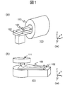
- FIG. 1 is an external view of the MRI apparatus of this embodiment.
- FIG. 1A shows a horizontal magnetic field type MRI apparatus 100 using a tunnel magnet that generates a static magnetic field with a solenoid coil.
- FIG. 1B shows a hamburger type (open type) vertical magnetic field type MRI apparatus 101 in which magnets are separated into upper and lower sides in order to enhance the feeling of opening.
- These MRI apparatuses 100 and 101 include a table 102 on which an inspection object 103 is placed. This embodiment can be applied to both the MRI apparatus 100 including the horizontal magnetic field type magnet 110 and the MRI apparatus 101 including the vertical magnetic field type magnet 111.
- the MRI apparatus 100 having the horizontal magnetic field type magnet 110 will be described as an example.
- any of these MRI apparatuses having these appearances can be used.
- various known MRI apparatuses can be used regardless of the form and type of the apparatus.
- a coordinate system 090 is used in which the static magnetic field direction is the z direction and the two directions perpendicular to the z direction are the x direction and the y direction, respectively.
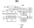
- FIG. 2 is a block diagram showing a schematic configuration of the MRI apparatus 100.
- the MRI apparatus 100 includes a horizontal magnetic field type magnet 110, a gradient magnetic field coil 131, a transmission RF coil 151, a reception RF coil 161, a gradient magnetic field power supply 132, a shim coil 121, a shim power supply 122, and a high frequency.
- a magnetic field generator 152, a receiver 162, a magnetic coupling prevention circuit driving device 180, a calculator 170, a sequencer 140, and a display device 171 are provided.
- Reference numeral 102 denotes a table on which the inspection object 103 is placed.
- the gradient magnetic field coil 131 is connected to the gradient magnetic field power supply 132 and generates a gradient magnetic field.
- the shim coil 121 is connected to the shim power source 122 and adjusts the uniformity of the magnetic field.
- the transmission RF coil 151 is connected to the high frequency magnetic field generator 152 and irradiates (transmits) the high frequency magnetic field to the inspection target 103.
- the reception RF coil 161 is connected to the receiver 162 and receives a nuclear magnetic resonance signal from the inspection target 103.
- the magnetic coupling prevention circuit driving device 180 is connected to a magnetic coupling prevention circuit (described later).
- the magnetic coupling prevention circuit is a circuit that prevents magnetic coupling between the transmission RF coil 151 and the reception RF coil 161 connected to the transmission RF coil 151 and the reception RF coil 161, respectively.
- the sequencer 140 sends commands to the gradient magnetic field power supply 132, the high frequency magnetic field generator 152, and the magnetic coupling prevention circuit driving device 180 to operate them.
- the command is sent in accordance with an instruction from the computer 170.
- the receiver 162 sets a nuclear magnetic resonance frequency as a reference for detection. For example, according to a command from the sequencer 140, a high-frequency magnetic field is applied to the inspection target 103 through the transmission RF coil 151. A nuclear magnetic resonance signal generated from the inspection object 103 by irradiating a high-frequency magnetic field is detected by the reception RF coil 161 and detected by the receiver 162.
- the computer 170 controls the operation of the entire MRI apparatus 100 and performs various signal processing. For example, a signal detected by the receiver 162 is received via an A / D conversion circuit, and signal processing such as image reconstruction is performed. The result is displayed on the display device 171. The detected signal and measurement conditions are stored in the storage medium 132 as necessary.
- the sequencer 140 is made to send an instruction so that each device operates at a preprogrammed timing and intensity. Further, when it is necessary to adjust the static magnetic field uniformity, the sequencer 140 sends a command to the shim power supply 122 to cause the shim coil 121 to adjust the magnetic field uniformity.
- the magnet 110 constitutes a static magnetic field forming unit for forming a static magnetic field
- the gradient magnetic field coil 131 and the gradient magnetic field power supply 132 constitute a gradient magnetic field forming unit for forming a gradient magnetic field
- the high frequency magnetic field generator 152 includes a high frequency magnetic field generator.
- the transmission RF coil 151 is a transmission coil that irradiates the inspection object 103 with the high-frequency magnetic field
- the reception RF coil 161 detects a nuclear magnetic resonance signal from the inspection object. It is a receiving coil
- the computer 170 constitutes an image reconstruction unit that reconstructs an image from the detected nuclear magnetic resonance signal.
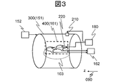
- the resonance frequency of the birdcage type RF coil 300 used as the transmission RF coil 151 is adjusted to the resonance frequency of the element to be excited.
- the magnetic resonance frequency of the hydrogen nucleus is adjusted so that the hydrogen nucleus can be excited.
- the array coil 400 used as the reception RF coil 161 is adjusted so as to detect a nuclear magnetic resonance signal of an element that can be excited by the birdcage type RF coil 300.
- the birdcage type RF coil 300 is arranged such that its axis is coaxial with the central axis of the magnet 110.
- the array coil 400 is disposed in the birdcage type RF coil 300. Further, as described above, the birdcage type RF coil 300 is connected to the high frequency magnetic field generator 152.
- the array coil 400 is connected to the receiver 162.
- the birdcage type RF coil 300 includes a magnetic coupling prevention circuit 210 that prevents magnetic coupling with the array coil 400.
- the magnetic coupling prevention circuit 210 is a circuit that prevents magnetic coupling between the transmission RF coil 151 (birdcage type RF coil 300) and the reception RF coil 161 (array coil 400). Call it.
- the inter-transmission / reception magnetic coupling prevention circuit 210 is inserted in series with a straight conductor (described later) of the birdcage type RF coil 300.
- the array coil 400 includes a magnetic coupling prevention circuit 220 that prevents magnetic coupling with the birdcage type RF coil 300.
- the magnetic coupling prevention circuit 220 is also a transmission / reception magnetic coupling prevention circuit that prevents magnetic coupling between the transmission RF coil 151 (birdcage type RF coil 300) and the reception RF coil 161 (array coil 400).
- the transmission / reception magnetic coupling prevention circuit 220 is inserted in series in each surface coil constituting the array coil 400.
- the magnetic coupling prevention circuit driving device 180 is connected to the transmission / reception magnetic coupling prevention circuit 210 and the transmission / reception magnetic coupling prevention circuit 220, respectively.
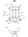
- a birdcage type RF coil 300 used as the transmission RF coil 151 of this embodiment will be described with reference to FIG.
- the birdcage type RF coil 300 of the present embodiment is adjusted so that the resonance frequency (nuclear magnetic resonance frequency) of the element to be excited becomes the resonance frequency, and irradiates the high frequency magnetic field of the nuclear magnetic resonance frequency.
- nuclear magnetic resonance frequency of the high frequency magnetic field to be irradiated with f 0.
- FIG. 4A is a block diagram for explaining the configuration of the birdcage type RF coil 300 of the present embodiment.
- the birdcage type RF coil 300 according to the present embodiment includes a plurality of linear conductors 301, end conductors 302 that connect the ends of the respective linear conductors 301, and a capacitor 303 that is inserted into the end conductors 302.
- the aforementioned transmission / reception magnetic coupling prevention circuit 210 is inserted in series with each linear conductor 301.
- the birdcage type RF coil 300 of the present embodiment includes two input ports 311 and 312.
- the first input port 311 and the second input port 312 are configured so that transmission signals having a phase difference of 90 degrees are input, and a high-frequency magnetic field is efficiently applied to the subject (inspection target) 103.
- FIG. 4B is a view for explaining the configuration of the inter-transmission / reception magnetic coupling prevention circuit 210 inserted into the straight conductor 301 of the birdcage type RF coil 300 and the connection with the magnetic coupling prevention circuit driving device 180.
- the inter-transmission / reception magnetic coupling prevention circuit 210 includes a PIN diode 211 and a control signal line 212.
- the PIN diode 211 is inserted in series with the straight conductor 301, and the control signal line 212 is connected to both ends of the PIN diode 211.
- the control signal line 212 is connected to the magnetic coupling prevention circuit driving device 180.
- a choke coil is inserted into the control signal line 212 in order to avoid high frequency mixing.
- the PIN diode 211 normally has a high resistance (off), and has a characteristic of being generally in a conductive state (on) when the value of the direct current flowing in the forward direction of the PIN diode 211 exceeds a certain value. In this embodiment, this characteristic is used, and on / off of the PIN diode 211 is controlled by a direct current output from the magnetic coupling prevention circuit driving device 180. That is, at the time of high-frequency signal transmission, a control current for turning on the PIN diode 211 is supplied, and the birdcage type RF coil 300 is caused to function as the transmission RF coil 151. Further, when receiving a nuclear magnetic resonance signal, the control current is stopped, and the birdcage type RF coil 300 is made to have a high impedance and opened.
- the birdcage type RF coil 300 is made to function as the transmission RF coil 151 at the time of high-frequency signal transmission, and the nuclear magnetism.
- the magnetic coupling with the array coil 400 which is the reception RF coil 161 is removed as an open state.
- the array coil 400 used as the reception RF coil 161 of the present embodiment will be described with reference to FIGS.
- the array coil 400 of this embodiment includes the two subcoils 410.
- Each of the two subcoils can receive a nuclear magnetic resonance signal, and each functions as one channel.
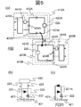
- FIG. 5A is a block diagram for explaining the configuration of the array coil 400 of the present embodiment.
- the two subcoils 410 constituting the array coil 400 of the present embodiment are referred to as a first subcoil 410A and a second subcoil 410B, respectively.
- Each of the first sub-coil 410A and the second sub-coil 410B is a surface coil having a loop configured on a plane.
- the first subcoil 410A and the second subcoil 410B each receive a nuclear magnetic resonance signal. The received signal is sent to the receiver 162.
- each subcoil 410 constituting the array coil 400 for each subcoil 410
- the last letter of the reference numeral is omitted.
- the first subcoil 410A includes a loop coil unit 420 (first loop coil unit 420A) that receives a nuclear magnetic resonance signal, a low (input) impedance signal processing circuit 430 (first low impedance signal processing circuit 430A), and And a magnetic coupling adjustment unit 441 (first magnetic coupling adjustment unit 441A) for connecting the loop coil unit 420 and the low impedance signal processing circuit 430.
- the magnetic coupling adjustment unit 441 includes at least one of a capacitor and an inductor.
- the loop portion (first loop 421A) of the first loop coil portion 420A is formed of a conductor.
- the first loop coil section 420A includes a capacitor 424A that is inserted in series with the inductor component of the first loop 421A.
- the inductor component and the capacitor 424A constitute a parallel resonance circuit.
- This capacitor 424A is referred to as a first parallel capacitor 424A in order to distinguish it from other capacitors.
- a capacitor 422A for adjusting the resonance frequency and a magnetic coupling prevention circuit 220 between transmission and reception are inserted in series in the first loop 421A.
- the capacitor 422A is referred to as a first series capacitor 422A in order to distinguish it from other capacitors.
- a case where two first series capacitors 422A are provided is illustrated, but the number of first series capacitors 422A may be one or more.
- the first subcoil 410A of the present embodiment is a circuit element for adjustment, and the first magnetic coupling adjustment unit 441A and the first sub-coil 410A inserted in series with respect to the inductor component of the first loop 421A.
- Serial capacitor 422A and a first parallel capacitor 424A that is inserted in series with the inductor component and uses the first loop coil section 420A as a parallel resonant circuit.
- One terminal on the loop coil unit 420 side of the low impedance signal processing circuit 430 is connected to one end of the parallel capacitor 424 of the loop coil unit 420 via the magnetic coupling adjustment unit 441.
- the other terminal on the loop coil unit 420 side of the low impedance signal processing circuit 430 is directly connected to the other end of the parallel capacitor 424 of the loop coil unit 420.
- the other terminal of the low impedance signal processing circuit 430 that is not on the loop coil section 420 side is connected to the receiver 162.
- the transmission / reception magnetic coupling prevention circuit 220 removes magnetic coupling with the birdcage type RF coil 300 that is the transmission RF coil 151.
- the second subcoil 410B has the same configuration as the first subcoil 410A. That is, the second sub-coil 410B includes a second loop coil unit 420B that is a parallel resonance circuit, a second low-impedance signal processing circuit 430B, a second loop coil unit 420B, and a second low-impedance signal processing circuit. And a second magnetic coupling adjustment unit 441B that connects 430B.
- the second loop coil section 420B includes a loop formed by a conductor (second loop 421B), a second series capacitor 422B inserted in series with the inductor component of the second loop 421B, A second parallel capacitor 424B inserted in series with the inductor component and having the second loop coil section 420B as a parallel resonant circuit.
- FIG. 5B is a diagram for explaining the configuration of the inter-transmission / reception magnetic coupling prevention circuit 220 inserted into the loop 421 and the connection between the inter-transmission / reception magnetic coupling prevention circuit 220 and the magnetic coupling prevention circuit driving device 180. is there.
- the transmission / reception magnetic coupling prevention circuit 220 includes a PIN diode 221, an inductor 222, and a control signal line 223.
- the PIN diode 221 and the inductor 222 are connected in series, and are connected in parallel to the capacitor 423.
- the capacitor 423 is a capacitor inserted into the loop 421.
- a control signal line 223 is connected to both ends of the PIN diode 221.
- the control signal line 223 is connected to the magnetic coupling prevention circuit driving device 180.
- a choke coil is inserted into the control signal line 223 (not shown) in order to avoid high frequency mixing. Inductor 222 and capacitor 423 are adjusted to resonate in parallel at the frequency of the received nuclear magnetic resonance signal.
- Parallel resonant circuits generally have a characteristic of high impedance (high resistance) at the resonance frequency. Therefore, when a current flows through the PIN diode 221, the PIN diode 221 is turned on, and the capacitor 423 of the loop 421 enters into a high impedance state in parallel with the inductor 222 at the frequency of the received nuclear magnetic resonance signal. Therefore, a part of the loop coil unit 420 becomes high impedance and is opened at the frequency of the nuclear magnetic resonance signal to be received, and the subcoil 410 having the loop coil unit 420 is also opened.
- the number of transmission / reception magnetic coupling prevention circuits 220 inserted into the subcoil 410 is not limited to this. Two or more may be inserted into each loop 421. The magnetic coupling can be sufficiently lowered by inserting a plurality.
- the configuration of the transmission / reception magnetic coupling prevention circuit 220 is not limited to the above configuration.
- a cross diode 221m may be used instead of the PIN diode 221 as in a modification of the transmission / reception magnetic coupling prevention circuit 220m shown in FIG.
- the cross diode 221m is turned on, and the capacitor 423 of the loop 421 resonates in parallel with the inductor 222 at the frequency of the received nuclear magnetic resonance signal to generate high impedance. It becomes a state.
- the magnetic coupling prevention circuit driving device 180 may not be provided.
- the first sub-coil 410A and the second sub-coil 410B are adjusted so that each can receive a nuclear magnetic resonance signal.
- the first subcoil 410A is adjusted so that the resonance frequency of the first subcoil 410A alone is different from the nuclear magnetic resonance frequency that is the frequency of the nuclear magnetic resonance signal to be transmitted and received.
- the first subcoil 410A is disposed at a position or configuration that can be magnetically coupled to the second subcoil 410B, and is intentionally magnetically coupled to the first loop 421A and the second loop 421B. , Respectively, are adjusted so that a circulating current path is formed and resonance occurs at the nuclear magnetic resonance frequency.
- the resonance frequency characteristic of the subcoil 410A alone is arranged and adjusted at a position that changes depending on the presence or absence of the second subcoil 410B.
- the first subcoil 410A and the second subcoil 410B are arranged at a position where magnetic coupling is possible. That is, the loop coil portion 420A of the first subcoil 410A and the loop coil portion 420B of the second subcoil 410B are arranged on substantially the same plane, and the first subcoil 410A and the second subcoil 410B are formed.
- the magnetic fields are arranged at positions where they can interfere with each other.
- the coil elements may be partially overlapped.
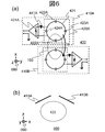
- FIG. 6A and FIG. 6B are diagrams for explaining the arrangement of the first sub-coil 410A and the second sub-coil 410B that constitute the array coil 400 used as the reception RF coil 161 of the present embodiment. is there.
- the vertical direction of the paper is the X-axis direction
- the horizontal direction is the Y-axis direction
- the direction perpendicular to the paper surface is the Z-axis direction.
- the vertical direction on the paper surface is the Z-axis direction
- the horizontal direction is the X-axis direction
- the vertical direction is the Y-axis direction.
- the first subcoil 410A and the second subcoil 410B have a surface formed by the loop 421 of each loop coil portion 420 in the magnetic field direction.
- a description will be given by taking as an example the case of being arranged so as to be a surface relatively close to a surface perpendicular to the (Z-axis direction).
- the loop 421 of the loop coil unit 420 is circular.
- the diameters of the loops 421A and 421B of the first loop coil portion 420A and the second loop coil portion 420B are 100 mm.
- the first sub-coil 410A is disposed on a surface rotated counterclockwise by 20 degrees from the XY plane with the Y axis as the rotation axis from the XY plane.
- the sub-coil 410B is arranged on a plane rotated clockwise from the XY plane by 20 degrees about the Y axis as a rotation axis.
- the distance between the origins of the circles of the circular loops 421 of the two subcoils 410 is 132 mm.
- k is a magnetic coupling coefficient, and is a value indicating the proportion of the magnetic flux generated by the first subcoil 410A to be coupled to the second subcoil 410B.
- the magnetic coupling coefficient k takes a value from 0 to 1.
- L 11 is the size of the inductor component of the loop 421A of the first subcoil 410A.
- L 21 is the size of the inductor component of the loop 421B of the second subcoil 410B.
- FIG. 6A illustrates a case where low input impedance signal amplifiers 431A and 431B are used as the first low impedance signal processing circuit 430A and the second low impedance signal processing circuit 430B.
- the low input impedance signal amplifier 431 as the low impedance signal processing circuit 430, the signal detected by the loop coil unit 420 can be immediately amplified, so that data with less noise can be acquired.
- the input impedance of the low input impedance signal amplifier 431 is 2 ⁇ .
- the low impedance signal processing circuit 430 is not limited to the signal amplifier 431 having a low input impedance.
- the magnetic coupling between the transmission RF coil 151 and the reception coil 161 is removed by the above-described method using the magnetic coupling prevention circuits 210 and 220 between transmission and reception.
- the transmission RF coil 151 is always in an open state, and the description of removing the magnetic coupling between the transmission RF coil 151 and the reception RF coil 161 is omitted.
- the first sub-coil 410A and the second sub-coil 410B of the array coil 400 of the present embodiment include a first magnetic coupling adjustment unit 441A, the second magnetic coupling adjustment unit 441B, the first series capacitors 422A, 423A, The above functions are realized by adjusting the values of the second series capacitors 422B and 423B, the first parallel capacitor 424A, and the second parallel capacitor 424B.
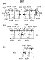
- FIG. 7A shows an equivalent circuit 600 of the array coil 400 of the present embodiment.
- the value L 11 of the inductor 621A is the inductor component of the first loop 421A
- the value C 11 of the series capacitor 622A is the synthesis of the series capacitors (422A, 423A) inserted into the first loop 421A.
- the value L 21 of the inductor 621B is an inductor component of the second loop 421A
- the value C 21 of the series capacitor 622B is a composite value of the series capacitors (422B, 423B) inserted into the second loop 421B. It is.
- the value C 14 in the parallel capacitor 624A is the value of the parallel capacitor 424A
- the value C 24 in the parallel capacitor 624B is the value of the parallel capacitor 424B.
- the magnetic coupling adjustment unit 441 uses an inductor.
- the value L 12 of the inductor 641A is the value of the inductor of the first magnetic coupling adjustment unit 441A.
- the value L 22 of the inductor 641B is the value of the inductor of the second magnetic coupling adjustment unit 441B.
- an inductor is used for the magnetic coupling adjustment unit 441, but the present invention is not limited to this.
- the parallel capacitor 624 and the magnetic coupling adjustment unit 441 are connected by a conductor. Since the conductor also has an inductor component, a parallel resonant circuit is formed by the parallel capacitor 624, the magnetic coupling adjustment unit 441, and the inductor component of the conductor connecting them without adding an additional inductor.
- the magnetic coupling adjustment unit 441 may be a capacitor.
- a parallel circuit of a capacitor and an inductor may be used. In the following description, it is assumed that there is no inductor component of the conductor connecting the parallel capacitor 624 and the magnetic coupling adjustment unit 441 for the sake of simplicity.
- the value Z 11 of the impedance 632A is the value of the input impedance of the low input impedance signal amplifier 431A used as the first low impedance signal processing circuit 430A.
- the value Z 21 of the impedance 632B is the value of the input impedance of the low input impedance signal amplifier 431B used as the second low impedance signal processing circuit 430B. Since these impedances Z 11 and Z 21 are sufficiently low impedances, they are considered as 0 ⁇ (short circuit) hereinafter.
- the mutual inductance M is a value of mutual inductance between the first loop coil portion 420A (620A) and the second loop coil portion 420B (620B).
- the frequency (nuclear magnetic resonance frequency) of the detected nuclear magnetic resonance signal is assumed to be f 0 .
- the resonance frequency of the first sub-coils 410A (610A) alone f 10 the resonance frequency of the second sub-coils 410B (610B) alone and f 10.
- First loop coil portion 420A is a parallel resonant circuit the resonance frequency of the (620A) f 12, the resonant frequency of the second loop coil portion 420B (620B) and f 22.
- the first low impedance signal viewed from the first low impedance signal processing circuit 430A (631A) at the time of signal reception.
- the resonance frequency of the first sub-coil 410A (610A) (hereinafter referred to as the first resonance unit) excluding the processing circuit 430A (631A) is f 11 , as viewed from the second low impedance signal processing circuit 430B (631A).
- the resonance frequency of the second sub-coil 410B (610B) (hereinafter referred to as the second resonance unit) excluding the first low-impedance signal processing circuit 430A (631A) is defined as f 21 .
- Each circuit element of the array coil 400 of the present embodiment is adjusted to satisfy the following expressions (2) to (5).
- a parallel resonance circuit (hereinafter, L 22 C 24 resonance) including the adjustment inductor 441B (641B) of the second subcoil 410B (610B) and the parallel capacitor 424B (624B).
- the resonance frequency of the circuit is different from the nuclear magnetic resonance frequency f 0 . Therefore, at the time of signal reception, both ends of the capacitor 424B of the second subcoil 410B do not have high resistance but are magnetically coupled to the first subcoil 410A.
- FIG. 7B shows an equivalent circuit 601 of the first subcoil 410A (first resonance portion) excluding 631A).
- the first resonating part of the first subcoil 410A has an inductor component (L 11 ) of the first loop 421A and an inductor component of the second loop 421B.
- a circuit 601 in which (L 21 ) is coupled by magnetic coupling is obtained.
- an inductor 627 is obtained by removing the mutual inductance M from the mutual inductance M, the value L 11 -M of the inductor 626A, and the value L 21 -M of the inductor 626B.
- each circuit element is caused by the magnetic coupling to cause the first loop 421A to receive a clockwise (clockwise) circular current I 1.
- the loop 421B By adjusting the loop 421B so that a counterclockwise circular current I 2 flows, the loop 421A and the loop 421B effectively form a current path like a butterfly coil, and current flows. (FIG. 7B).
- a parallel resonant circuit (hereinafter, L 12 C) including the adjusting inductor 441A (641A) of the first subcoil 410A (610A) and the parallel capacitor 424A (624A) is adjusted.
- the resonance frequency of 14 ) is called a nuclear magnetic resonance frequency f 0 . Therefore, at the time of signal reception, both ends of the capacitor 424A of the first subcoil 410A have high resistance. Therefore, the second subcoil 410B is not magnetically coupled to the first subcoil 410A.
- the second sub-coil 410B (first resonance portion) excluding the low-impedance signal processing circuit 430B (631B) as viewed from the second low-impedance signal processing circuit 430B (631B) when adjusted according to the equation (5) 7) shows an equivalent circuit 602 of FIG.
- the first subcoil 410A is adjusted to prevent magnetic coupling with the first subcoil 410B. Therefore, at the time of signal reception, the resonance portion of the second subcoil 410B becomes the same circuit 602 as that of the second subcoil 410B alone, as shown in FIG. 7C.
- the single resonance frequency f 10 of the first subcoil 410A is different from the nuclear magnetic resonance frequency f 0 .
- the resonance frequency f 20 of the second subcoil 410B alone, the resonance frequency f 11 of the first resonance unit at the time of signal reception, and the second loop
- the resonance frequency f 22 of the coil section 420B is equal to the nuclear magnetic resonance frequency f 0 .
- the second subcoil 410B can detect a nuclear magnetic resonance signal alone.
- the first subcoil 410A is magnetically coupled to the second subcoil 410B during signal reception. At this time, the resonance frequency of the first resonance part becomes equal to the nuclear magnetic resonance frequency f 0 . Therefore, the subcoil 410A can also detect a nuclear magnetic resonance signal in a magnetically coupled state.
- the adjustment is performed by the values of the series capacitor 622, the parallel capacitor 624, and the adjustment inductor 641 as described above.
- the value of the inductor 621 of the loop 421 is determined by the shape of the loop 421 and cannot be changed.
- the mutual inductance value M is determined by the shape and the arrangement relationship.
- each subcoil 410 can receive a nuclear magnetic resonance signal to be detected.
- the first subcoil 410 is magnetically coupled to the second subcoil 410 and functions as a subcoil having a wide and deep sensitivity region. Furthermore, by adjusting the value of the capacitor or inductor of the magnetic coupling adjustment unit 441, the magnitude of the magnetic coupling can be changed to adjust the sensitivity distribution.
- the second subcoil 410 is not magnetically coupled to the first subcoil 410 and functions as a single subcoil as shown in FIG. Accordingly, at the time of signal reception, the first subcoil 410A and the second subcoil 410B exhibit different sensitivity distributions with respect to the imaging region. Therefore, it functions as a multi-channel coil.
- the resonance frequency of the parallel resonance circuit (L 22 C 24 resonance circuit) formed by the inductor 641B and the parallel capacitor 624B is set to be smaller than f 0. To do.
- each circuit element of the second subcoil 410B is adjusted.
- the loop coil portion 420A of the first subcoil 410A is in an open state.
- the values of the capacitance C 21 of the series capacitor 622B and the capacitance C 24 of the parallel capacitor 624B are adjusted. Here, these values are adjusted so that the equivalent circuit 602 shown in FIG. 7C resonates at 124 MHz, and the impedance at both ends of the series circuit of the inductor 641B and the parallel capacitor 624B becomes 50 ⁇ .
- the values of L 22 and C 24 are determined so that the parallel resonant circuit formed by the adjusting inductor 641B and the parallel capacitor 624B operates as a capacitor. This is adjusted based on the characteristic principle of the parallel resonant circuit. The characteristic principle of this parallel resonant circuit will be described later. Specifically, these values are adjusted so that the resonance frequency of the parallel resonance circuit (L 22 C 24 resonance circuit) formed by the inductor 641B and the parallel capacitor 624B is smaller than f 0 . For example, 90 MHz is used as a value smaller than f 0 .
- each circuit element of the first subcoil 410A is adjusted.
- each circuit element of the second subcoil 410B is adjusted as described above.
- the equivalent circuit 601 shown in FIG. 7B resonates at 124 MHz, and the series capacitor is set so that the impedance at both ends of the series circuit of the inductor 641A and the parallel capacitor 624A (C 14 ) is 50 ⁇ . adjust the values C 11 and the value C 14 in the parallel capacitor 624A of 622A.
- the second sub-coil 410B to block the magnetic coupling and the first sub-coil 410A since the second sub-coil 410B to block the magnetic coupling and the first sub-coil 410A, the value C 14 value L 12 and parallel capacitor 624A of the adjusting inductor 641A, so as to satisfy equation (5) at the same time adjust. Accordingly, when viewed from the second subcoil 410B, the first subcoil 410A can be viewed as a circuit in which a high impedance is inserted into the first loop 421A. Therefore, the second subcoil 410B is not magnetically coupled to the first subcoil 410A.
- the adjustment of the first subcoil 410A and the second subcoil 410B may be repeated several times as necessary.
- the array coil 400 of this embodiment resonates at the nuclear magnetic resonance frequency and receives a nuclear magnetic resonance signal.
- the size of the coil is effectively expanded and the sensitivity region is expanded. Then, a current distribution such as a butterfly coil or a large surface coil is formed, a sensitivity distribution that cannot be obtained with only two small surface coils is formed, and a signal is acquired efficiently (with high sensitivity).
- the sensitivity can be increased by using this embodiment.
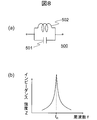
- FIG. 8A and FIG. 8B are diagrams for explaining the operation of the parallel resonant circuit.
- the parallel resonant circuit 500 includes an inductor 502 (L) and a capacitor 501 (C) connected in parallel.
- the impedance Z at both ends of the parallel resonant circuit 500 is expressed by the following formula (6).
- the impedance Z is expressed by Equation (7), and the parallel resonant circuit 500 operates as an inductive reactance (inductor).
- the apparent inductance value L ′ of the parallel resonant circuit 500 is expressed by Expression (8).
- the impedance Z is expressed by Equation (9), and the parallel resonance circuit 500 operates as a capacitive reactance (capacitor).
- the apparent capacitance value C ′ of the parallel resonant circuit 500 is expressed by Expression (10).
- the parallel resonance circuit 500 operates differently at the boundary of the resonance frequency f R according to the frequency f of the applied voltage.
- this property of the parallel resonant circuit 500 is used to adjust each circuit element of the array coil 400 as described above.
- 9A to 9E show the results calculated by the electromagnetic field simulator.
- 9A and 9B are a sensitivity distribution 511 of the first subcoil 410A and a sensitivity distribution 512 of the second subcoil 410B, respectively.
- 9C and 9D show the sensitivity distribution 513 of the first channel (first subcoil 410A) and the second channel (second subcoil) of the conventional two-channel array coil (RF coil). 410B).
- FIG. 9E shows a sensitivity profile 521 (broken line) on the Z axis after combining the sensitivities of the first sub-coil 410A and the second sub-coil 410B of the present embodiment.
- the resonance frequency of the parallel resonance circuit (L 22 C 24 resonance circuit) formed by the adjustment inductor 641B (L 22 ) and the parallel capacitor 624B (C 24 ) is adjusted to be 90 MHz, which is a value smaller than f 0 .
- a solid line 522 is a sensitivity distribution profile when the magnetic coupling of the conventional RF coil is removed.
- the array coil 400 has a sensitivity area widened by magnetic coupling, and has a high sensitivity in the object (inspection object) 103 area.
- the MRI apparatus 100 of the present embodiment includes the static magnetic field forming unit that forms the static magnetic field, the gradient magnetic field forming unit that forms the gradient magnetic field, the high-frequency magnetic field generation unit that generates the high-frequency magnetic field, and the high-frequency field.
- a transmission coil 151 that irradiates a magnetic field to the inspection object a reception coil 161 that detects a nuclear magnetic resonance signal from the inspection object, and an image reconstruction unit that reconstructs an image from the detected nuclear magnetic resonance signal.
- the receiving coil 161 has a first loop coil portion 420A made of a conductor, a first subcoil 410A capable of transmitting and receiving a nuclear magnetic resonance signal, and a second loop coil portion 420B made of a conductor.
- a second subcoil 410B capable of transmitting and receiving nuclear magnetic resonance signals
- the first subcoil 410A includes the first subcoil 410A.
- the single resonance frequency is different from the nuclear magnetic resonance frequency that is the frequency of the nuclear magnetic resonance signal to be transmitted and received, and is magnetically coupled to the second sub-coil 410B, thereby the loop of the first loop coil section and the A high-frequency coil (array coil 400) that is arranged and adjusted to form a current path that circulates in the loop of the second loop coil section and resonates at the nuclear magnetic resonance frequency, and transmits
- the coil 151 and the reception coil 161 include magnetic coupling prevention circuits 210 and 220 that prevent magnetic coupling between the transmission coil 151 and the reception coil 161, respectively.
- the first subcoil 410A includes a first magnetic coupling adjustment unit 441A that connects the first loop coil unit 420A and a first low impedance signal processing circuit 430A to which the first subcoil 410A is connected. Further prepare.
- the first loop coil section 420A is inserted in series with the inductor component of the loop 421A and the first series capacitor 422A inserted in series with the inductor component, and the first loop coil section And a first parallel capacitor 424A having 420A as a parallel resonance circuit.
- the second subcoil 410B includes a second magnetic coupling adjustment unit 441B that connects the second loop coil unit 420B and a second low impedance signal processing circuit 430B to which the second subcoil 410B is connected. Further prepare.
- the second loop coil unit 420B is inserted in series with the inductor component of the loop 421B and the second series capacitor 422B inserted in series with the inductor component.
- the first magnetic coupling adjustment unit 441A includes at least one of a capacitor and an inductor as a first adjustment circuit element.
- the second magnetic coupling adjustment unit 441B includes at least one of a capacitor and an inductor as a second adjustment circuit element.
- the first subcoil 410A and the second subcoil 410B include the first adjustment circuit element, the second adjustment circuit element, the first series capacitor 422A, the second series capacitor 422B, and the first Is adjusted by adjusting the values of the parallel capacitor 424A and the second parallel capacitor 424B. Further, the first subcoil 410 and the second subcoil are disposed at a position where magnetic coupling is possible.
- the array coil 400 of this embodiment arranged and adjusted as described above is tuned to the nuclear magnetic resonance frequency f 0 .
- the first subcoil 410A shares the second subcoil 410B and the loop coil portions 420A and 420B to broaden the sensitivity region and detects the signal, and the second subcoil 410B A signal can be detected with high sensitivity without magnetic coupling with the subcoil 410A.
- a sensitivity distribution that cannot be obtained with two small surface coils is formed, and a signal can be acquired efficiently (with high sensitivity).
- the first subcoil 410A and the second subcoil 410B have different sensitivity distributions with respect to the imaging region. For this reason, the array coil 400 of this embodiment maintains a multi-channel characteristic of being composed of a plurality of coils having different sensitivity distributions within the imaging region, and enables high-speed imaging.
- both a multi-channel and a wide and deep sensitivity region can be achieved. Further, this multi-channel, wide sensitivity region, and high sensitivity are realized by adjusting the arrangement and the value of the circuit element. Therefore, the configuration is not complicated.
- the MRI apparatus of this embodiment can obtain high-quality images at high speed.
- the low input impedance signal amplifier 431 is used for the low impedance signal processing circuit 430.
- the circuit element used as the low impedance signal processing circuit 430 is not limited to this.
- a low input impedance conversion circuit may be used.
- the second low impedance signal processing circuit 430 has a low impedance when viewed from the first subcoil 410A. Any circuit may be used.
- the array coil 400 to be developed can be optimized and the sensitivity is improved.
- size of the mutual inductance M is adjusted with the positional relationship of the 1st subcoil 410A and the 2nd subcoil 410B at the time of arrangement
- the method of adjusting the magnitude of the mutual inductance M is not limited to this.
- a coupling inductor 451 may be arranged in a part of each loop 421, and the magnetic coupling may be adjusted using this.
- the first subcoil 410A further includes a first coupled inductor 451A
- the second subcoil 410B further includes a second coupled inductor 451B.
- the first subcoil 410A and the second subcoil 410B are magnetically coupled by the first coupled inductor 451A and the second coupled inductor 451B.
- Only one subcoil 410 may be attached to the coupled inductor 451.
- the magnitude of the mutual inductance M can be freely adjusted regardless of the arrangement position of the two subcoils 410.
- the array coil 400 includes the coupling inductor 451, thereby reducing the restriction on the arrangement position of the two subcoils 410. For example, by disposing them at positions apart from each other, a large coil loop can be formed as a whole, and the depth sensitivity is improved.
- each sub-coil ⁇ Another example of arrangement position of each sub-coil>
- the arrangement surface is not limited to this. Any arrangement may be used as long as the rotating magnetic field in the direction perpendicular to the sexual magnetic field generated by the array coil 400 in the region of interest can be detected or generated more efficiently than each subcoil 410 alone.
- the array coil 400 may be arranged on a surface having an angle close to a surface parallel to the magnetic field direction.
- the first subcoil 410A may be arranged on a plane perpendicular to the magnetic field
- the second subcoil 410B may be arranged on a plane horizontal to the magnetic field.
- the arrangement angle is not limited to this angle. Both may be disposed on the same plane, may be disposed on surfaces that are perpendicular to each other, or may be disposed on two different parallel surfaces. Further, the arrangement may be such that the rotating magnetic field can be efficiently detected or generated from the phase difference between the currents flowing in the loops 421A and 421B.
- the arrangement of the array coil 400 can be optimized, and a nuclear magnetic resonance signal can be acquired with high sensitivity.
- the resonance frequency may be another value.
- FIG. 11 shows sensitivity profiles 531, 532, 533, and 534 when the resonance frequency of the L 22 C 24 resonance circuit is changed to 123 MHz, 111 MHz, 100 MHz, and 90 MHz. Both are sensitivity profiles on the Z-axis after combining the sensitivity of the first subcoil 410A and the second subcoil 410B of the present embodiment.
- the sensitivity of the array coil 400 of this embodiment is increased by setting the resonance frequency of the L 22 C 24 resonance circuit to a frequency different from f 0 .
- the magnitude of the difference between the resonance frequency of the L 22 C 24 resonance circuit and f 0 is not limited. However, it is desirable that the difference between the resonance frequency of the L 22 C 24 resonance circuit and f 0 be different by 10% or more.
- the array coil 400 of this embodiment adjusts the L 22 C 24 resonance circuit to a frequency different from f 0 (124 MHz) and increases the sensitivity by actively coupling the two subcoils 410. Can do.
- the circuit element may be adjusted by setting the resonance frequency of the L 22 C 24 resonance circuit to a frequency higher than f 0 .
- a clockwise current flows clockwise through the first loop 421A and the second loop 421B, and the first loop 421A and the second loop 421B have a large current.
- a current distribution like a surface coil can be formed.
- the sensitivity of the array coil 400 can be improved by changing the resonance frequency and changing the coupling amount, as in the case where the frequency is set lower than f 0 .
- each loop 421 is arranged so that the sign of the coupling coefficient between the first loop 421A and the second loop 421B is opposite to that of the present embodiment, the relationship between the resonance frequency and the current flow is Vice versa. That is, if the resonant frequency of the resonant circuit L 22 C 24 is greater than f 0 (124 MHz), the effective electric current path, such as a butterfly coil is formed, if f 0 is smaller than the effective large surface A current distribution like a coil is formed.
- the array coil 400 of this embodiment has a high degree of freedom in designing the loop 421.
- loops of the same size and shape are used as the first loop 421A and the second loop 421B.
- both may have different shapes or different sizes.
- the degree of freedom of the arrangement pattern is increased.
- coils having the same shape are used for the first subcoil 410A and the second subcoil 410B, but the combination of shape and size is not limited. It may be different. By combining different shapes, an optimum coil suitable for the subject (inspection object) 103 can be realized. In addition, the strength of magnetic coupling can be adjusted. Three capacitors are inserted in the loop 421 of the loop coil unit 420, but the present invention is not limited to this. At least one or more may be inserted.
- the shape of the loop 421 of each sub-coil 410 has been described by taking a rectangular shape on a substantially plane or a circular single loop as an example.
- the shape of the loop 421 is not limited to these. Any equivalent circuit can be used as long as it is equivalent to the equivalent circuit 600.
- the first loop 462A and the second loop 462B may have a bowl-like shape arranged to face each other in a cylindrical shape.
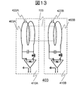
- FIG. 12 shows an array coil 402 having a saddle-shaped loop (a saddle-shaped array coil).
- the z-axis direction of the coordinate system 090 is the static magnetic field direction.
- the first loop 463A and the second loop 463B have a solenoid coil shape and may be arranged adjacent to each other.
- FIG. 13 shows an array coil (solenoid array coil) 403 having a solenoid type loop.
- the z-axis direction of the coordinate system 090 is the static magnetic field direction.
- the operation principle is the same as that of the array coil 400 of this embodiment. That is, the loops 462A and 463A of the first subcoil 410A operate in combination with the loops 462B and 463B of the second subcoil 410B. On the other hand, the second subcoil 410B operates as a single unit.
- each subcoil 410 constituting the saddle type array coil 402 and the solenoid type array coil 403 has sensitivity to the nuclear magnetic resonance signal to be detected. Further, since the loops 462A and 463A of the first subcoil 410A are coupled to the loops 462B and 463B of the second subcoil 410B by magnetic coupling, they can be regarded as large coil loops, and the sensitivity range is widened. The second subcoil 410B is not coupled to the first subcoil 410A and has a sensitivity region. For this reason, the sensitivity distributions of both subcoils in the imaging region are different and the number of channels can be maintained. Therefore, array coils 402 and 403 having a wide sensitivity region while maintaining the number of channels can be realized.
- the loop-shaped array coil 402 has a loop-shaped 462, as shown in FIG. 12, in the loop-shaped loop 462, the subject's arms, legs, torso, etc. are inspected.
- the target 103 is arranged. Thereby, in addition to the surface of the inspection object 103, the nuclear magnetic resonance signal from the region in the deep direction can be detected with high sensitivity.
- the loop 463 has a solenoid shape, as shown in FIG. 13, the subject to be inspected 103 such as an arm, a leg, and a torso of the subject is included in the solenoid shaped loop 463. Place.
- the solenoid type array coil 403 has a uniform sensitivity distribution over a wider area than the saddle type array coil 402.
- loops of the same shape and size are used for the first loops 462A and 463A and the second loops 462B and 463B, respectively.
- the size and shape of both may be different.
- the degree of freedom of the arrangement pattern is increased.
- the size of the magnetic coupling can be easily adjusted.
- the first subcoil 410A is magnetically coupled to the other of the second subcoil 410B and the second subcoil 410B is the first subcoil 410A during signal reception. And not magnetically coupled.
- any subcoil 410 may be configured to be magnetically coupled to the other when receiving a signal.
- the second subcoil 410B is different from the nuclear magnetic resonance frequency in the resonance frequency of the second subcoil 410B alone and is magnetically coupled to the first subcoil 410A.
- Each of the second loops 421B may be adjusted to form a current path that circulates and resonate at a nuclear magnetic resonance frequency.
- the configuration of the array coil 404 of this modification is the same as the configuration of the array coil 400 of this embodiment as shown in FIG.
- the adjustment method of the value of each circuit element (adjustment inductor 441, series capacitor 422, parallel capacitor 424) which comprises is different.
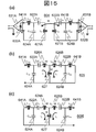
- a method for adjusting the value of each circuit element of the array coil 404 will be described using an equivalent circuit 604 of the array coil 404 shown in FIG.
- each capacitor and its value, each inductor and its value, and the resonance frequency of each circuit are represented by the same reference numerals as those of the equivalent circuit 600 of the above embodiment.
- each circuit element constituting the array coil 404 is adjusted to satisfy the following expressions (11) to (15).
- f 20 ⁇ f 0 (13)
- the resonance frequency of the L 22 C 24 resonance circuit of the second subcoil 410B (610B) is different from the nuclear magnetic resonance frequency f 0 . Therefore, at the time of signal reception, both ends of the capacitor 424B of the second subcoil 410B do not have high resistance but are magnetically coupled to the first subcoil 410A.
- FIG. 15B shows an equivalent circuit 605 of the first resonance portion of the first subcoil 410A in a state where the first loop coil portion 420A and the second loop coil portion 420B are magnetically coupled by the above adjustment. . That is, at the time of signal reception, as shown in FIG. 15B, the first resonance part of the first subcoil 410A is coupled to the first loop coil part 420A and the second loop coil part 420B by magnetic coupling. Circuit 605.
- the resonance frequency of the L 12 C 14 resonance circuit of the first subcoil 410A (610A) is different from the nuclear magnetic resonance frequency f 0 . Therefore, at the time of signal reception, both ends of the capacitor 424A of the first subcoil 410A do not have high resistance but are magnetically coupled to the second subcoil 410B.
- FIG. 15C shows an equivalent circuit 606 of the second resonance portion of the second subcoil 410B in a state where the first loop coil portion 420A and the second loop coil portion 420B are magnetically coupled by the above adjustment. Show. That is, at the time of signal reception, as shown in FIG. 15C, the second resonating portion of the second subcoil 410B is coupled to the first loop coil portion 420A and the second loop coil portion 420B by magnetic coupling. Circuit 606.
- the single resonance frequencies f 10 and f 20 of the first subcoil 410A and the second subcoil 410B are changed to the nuclear magnetic resonance, respectively. This is different from the frequency f 0 .
- the resonance frequency f 11 of the first resonance unit and the resonance frequency f 22 of the second resonance unit at the time of signal reception become the nuclear magnetic resonance frequency. equal to f 0 .
- the subcoil 410A and the subcoil 410B can detect the nuclear magnetic resonance signal in a magnetically coupled state.
- each circuit element will be described as a specific example with the nuclear magnetic resonance frequency f 0 as the nuclear magnetic resonance frequency 124 MHz of hydrogen at a static magnetic field strength of 3T (Tesla).
- the equivalent circuits 605 and 606 shown in FIGS. 15B and 15C resonate at 124 MHz, respectively, and both ends of the series circuit of the inductor 641A and the parallel capacitor 624A (C 14 ). Each circuit element is adjusted so that the impedance becomes 50 ⁇ . Then, based on the characteristic principle of the parallel resonance circuit so that the value of the adjustment inductor 641 and the value of the parallel capacitor 624 satisfy the above-described formulas, and the current flow at the time of coupling becomes a desired mode, adjust.
- either the first subcoil 410A or the second subcoil 410B may be adjusted first.
- the resonance characteristics of the other subcoil 410 are also affected. Therefore, the adjustment of the value of each circuit element of each subcoil 410 is repeated several times, and the first subcoil 410A And the second subcoil 410B are adjusted so as to resonate at 124 MHz.
- the array coil 404 of this modification resonates at the nuclear magnetic resonance frequency and receives a nuclear magnetic resonance signal.
- first subcoil 410A shares the second loop 421B and expands the sensitivity region
- second subcoil 410B shares the first loop 421A and expands the sensitivity region
- each subcoil constituting the array coil 404 has sensitivity to the received nuclear magnetic resonance signal.
- the first sub-coil 410A is coupled to the second loop 421B by magnetic coupling, it can be regarded as a large coil loop, and the sensitivity region is expanded. Specifically, since the sensitivity distribution is similar to that of a butterfly coil, deep sensitivity can be obtained.
- the second subcoil 410B is coupled to the first loop 421A by magnetic coupling, the second subcoil 410B can be regarded as a large coil loop and the sensitivity region is widened. Specifically, since the sensitivity distribution is similar to that of a butterfly coil, deep sensitivity can be obtained.
- the array coil 404 according to this modification operates as an array coil having a wide sensitivity region and high sensitivity without reducing the number of channels. Therefore, since the array coil is a multi-channel array coil having a wide sensitivity region, the array coil 404 of this modification is magnetically coupled to each other, and achieves both a multi-channel and a wide and deep sensitivity region. Further, since this is realized by adjusting the arrangement of the sub-coils 410 and the values of the circuit elements, the structure is not complicated.
- the same value (90 MHz) is used as the resonance frequency of the L 12 C 14 resonance circuit and the L 22 C 24 resonance circuit when adjusting each circuit element, but the present invention is not limited to this. Both may be different. By using different values for both, the current flowing through the magnetic coupling destination changes, so that it is possible to design a sensitivity region suitable for the purpose.
- the magnitude of the difference between the resonance frequency of these resonance circuits and f 0 is not limited. However, it is desirable that the difference between the resonance frequency of the L 22 C 24 resonance circuit and f 0 be different by 10% or more.
- an array coil is configured by combining two subcoils.
- an example is shown in which an array coil is configured by combining three or more subcoils to realize multichannels, a wide sensitivity region, and high sensitivity. Sensitivity can be improved by using a plurality of coils.
- the MRI apparatus of this embodiment basically has the same configuration as the MRI apparatus 100 of the first embodiment.
- the present embodiment will be described focusing on the configuration different from the first embodiment.
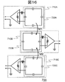
- FIG. 16 is a diagram for explaining the array coil 700 of the present embodiment.
- the array coil 700 of this embodiment includes a first subcoil 710A, a second subcoil 710B, and a third subcoil 710C. These are arranged in this order, and are arranged at positions where adjacent channels (subcoils 710) can be magnetically coupled.
- the configuration of the first subcoil 410A and the third subcoil 710C is the same as that of the first subcoil 410A of the first embodiment.
- the second subcoil 410B is the same as the second subcoil 410B of the first embodiment.
- Each capacitor and inductor are adjusted so as to satisfy Expressions (2) to (5), as in the first embodiment.
- the high-frequency coil (array coil 700) of the present embodiment includes a third loop coil portion 720A in the first subcoil 710A and the second subcoil 710B, and can transmit and receive a nuclear magnetic resonance signal.
- the third subcoil 710C further includes a subcoil 710C, and the third subcoil 710C has a resonance frequency different from that of the nuclear magnetic resonance frequency and is magnetically coupled to the second subcoil 710B.
- the loop of the third loop coil unit 720C and the loop of the second loop coil unit 720B are respectively adjusted to form a current path that circulates and resonate at the nuclear magnetic resonance frequency.
- the subcoils 710A, 710B, and 710C of the present embodiment are adjusted to resonate at the nuclear magnetic resonance frequency of the detection target atom.
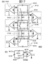
- the resonance is adjusted to resonate at a nuclear magnetic resonance frequency of 124 MHz for hydrogen at a static magnetic field strength of 3 T (Tesla).
- the circuit elements of the second subcoil 710B are adjusted so that the L 22 C 23 resonance circuit does not resonate at the nuclear magnetic resonance frequency. That is, it is adjusted so as not to have a high resistance when receiving a signal of this frequency.
- the first subcoil 710A and the third subcoil 710C are adjusted so that the L 12 C 14 resonance circuit resonates at the nuclear magnetic resonance frequency and becomes high resistance when receiving a signal of this frequency.
- the loop coil portion 720A of the first subcoil 710A is magnetically coupled to the loop coil portion 720B of the second subcoil 710B when receiving a signal. This is because the first subcoil 710A and the second subcoil 710B are arranged at positions where magnetic coupling is possible, and each circuit element of the second subcoil 710B is adjusted according to the above equation (4). This is because the resistance does not become high when the signal is received (magnetic coupling is not removed).
- the magnitude of the mutual inductance between the first subcoil 710A and the second subcoil 710B in this case is M1.
- the first loop coil portion 720A is hardly magnetically coupled to the loop coil portion 720C of the third subcoil 710C.
- the reverse is also true. This is due to the fact that the two are separated in distance and the L 12 C 14 resonance circuit resonates at the nuclear magnetic resonance frequency and becomes high resistance when receiving a signal of this frequency.
- the third loop coil unit 720C is magnetically coupled to the second loop coil unit 720B when receiving a signal.
- the third subcoil 710C and the second subcoil 710B are arranged at positions where they can be magnetically coupled, and each circuit element of the second subcoil 710B is adjusted according to the above equation (4). This is because the resistance does not become high during signal reception (magnetic coupling is not removed).
- the magnitude of the mutual inductance between the third subcoil 710C and the second subcoil 710B in this case is M2.
- the second loop coil unit 720B is not magnetically coupled to the first loop coil unit 720A or the third loop coil unit 720C when receiving a signal. This is because both the first sub-coil 710A and the third sub-coil 710C are adjusted in accordance with the above formula (5) and have high resistance when receiving signals.
- the first subcoil 710A of the array coil 700 of the present embodiment is effectively coupled with the first loop coil portion 720A magnetically coupled to the second loop coil portion 720B at the time of signal reception.
- the third subcoil 710C receives a signal, the third loop coil portion 720C is magnetically coupled to the second loop coil portion 720B, so that the current path is effectively the same as that of the butterfly coil.
- each subcoil 710 resonates at the detection target nuclear magnetic resonance frequency.
- the first subcoil 710A and the third subcoil 710C are magnetically coupled to the second subcoil 710B, respectively, when receiving a signal, and effectively form a current path similar to that of the butterfly coil. Therefore, it has a wide and deep sensitivity region.
- the second subcoil 710B is not magnetically coupled to other subcoils 710 during signal reception. Therefore, each subcoil 710 exhibits a different sensitivity distribution with respect to the imaging region.
- the array coil 700 of this embodiment realizes a wide sensitivity region, high sensitivity, and multi-channel.
- the first subcoil 710A is coupled to the second subcoil 710A
- the third subcoil 710C is coupled to the second subcoil 710B
- the second subcoil 710B is Each circuit element is adjusted so as not to be coupled with any of them.
- each circuit element may be adjusted so that the first subcoil 710A and the second subcoil 710B are magnetically coupled to the third subcoil 710C, and the third subcoil 710C is not coupled to either.
- each circuit element may be adjusted so that the second subcoil 710B and the third subcoil 710C are magnetically coupled to the first subcoil 710A and the first subcoil 710A is not coupled to any of them.
- first subcoil 710A is coupled to the second subcoil 710B
- second subcoil 710B is coupled to the third subcoil 710C
- the third subcoil 710C is not coupled to any subcoil 710. It may be configured.
- magnetic coupling removal such as overlapping the part of the loop coil portion 720 to remove the magnetic coupling so that the third subcoil 710C is not magnetically coupled to the first subcoil 710A and the second subcoil 710B.
- Means may be provided.
- a sensitivity distribution different from that of the present embodiment can be realized, so that the degree of freedom in designing the sensitivity region is improved.
- each circuit element may be adjusted so that the second subcoil 710B is magnetically coupled to the first and third subcoils 710A and 710C.
- the array coil 700 of this embodiment and the array coil of its modification can be operated as an array coil having a wide sensitivity region without reducing the number of channels. Further, since this is realized by adjusting the arrangement of the sub-coils 710 and the values of the circuit elements, the structure is not complicated. Therefore, according to the array coil 700 of this embodiment, it is possible to achieve both a multi-channel and a wide and deep sensitivity region with a simple configuration. By using this array coil 700 as the reception RF coil 161, the MRI apparatus of this embodiment can obtain high-quality images at high speed.
- Variations of the first embodiment such as the types of circuit elements used in the low impedance signal processing circuit, the resonance frequency used when adjusting the circuit elements, the location of each subcoil, the presence or absence of a coupled inductor, the loop shape, the size of each subcoil, etc. Is also applicable to this embodiment.
- the MRI apparatus of this embodiment basically has the same configuration as the MRI apparatus 100 of the first embodiment.
- the present embodiment will be described focusing on the configuration different from the first embodiment.
- FIG. 17A and FIG. 17B are diagrams for explaining the array coil 800 of the present embodiment.
- the case where the array coil 800 includes five subcoils 810 will be described as an example.
- the number of subcoils 810 constituting the array coil 800 is not limited to this.
- the first subcoil 810A, the fourth subcoil 810D, the second subcoil 810B, the fifth subcoil 810E, and the third subcoil 810C are provided.
- each subcoil 810 is the same as that of the subcoil 410 of the first embodiment. That is, each subcoil 810 further includes a first magnetic coupling adjustment unit 841 that connects the loop coil unit 820 and the first low impedance signal processing circuit 830 to which the subcoil 810 is connected, and the first loop coil unit.
- 820 is a first series capacitor 822 inserted in series with the inductor component of the loop 821 and a first series capacitor 822 inserted in parallel with the inductor component, and the first loop coil unit 820 is used as a parallel resonant circuit.
- One parallel capacitor 824 is used as a parallel resonant circuit.
- each subcoil 810 is arranged so that adjacent subcoils 810 and a part of the loop 821 of the mutual loop coil section 820 overlap (overlapping). At this time, the overlap amount is determined so that the magnetic coupling between the adjacent subcoils 810 is removed. That is, the adjacent subcoils 810 are arranged so as to overlap so that the magnetic coupling is removed.
- the fourth loop coil portion 820D is disposed so as to have an overlap region with each of the first loop coil portion 820A and the second loop coil portion 820B.
- the area of the wrap region is determined so that the fourth subcoil 810D is not magnetically coupled to the first subcoil 810A and the second subcoil 810B.
- the fifth coil portion 820E is disposed so as to have an overlap region with each of the second loop coil portion 820B and the third loop coil portion 820C, and the area of the overlap region is the fifth loop portion 820E. It is determined that the subcoil 810E is not magnetically coupled to the second subcoil 810B and the third subcoil 810C.
- the first subcoil 810A, the second subcoil 810B, and the third subcoil 810C are each magnetically coupled to the subcoil that each subcoil 810 of the second embodiment is adjacent to when receiving a signal. It adjusts similarly to the modification which produces Hereinafter, adjustment of each circuit element of the fourth subcoil 810D and the fifth subcoil 810E will be described using the fourth subcoil 810D as an example with reference to FIG.
- the circuit obtained by removing the low impedance signal processing circuit 830D from the fourth subcoil 810D resonates at the detection target nuclear magnetic resonance frequency f 0 (124 MHz in the case of hydrogen), and the inductor 641A and the parallel capacitor 624A (C 14). ),
- the values of the series capacitors 822D (C 12 ) and 823D (C 13 ) are adjusted so that the impedance at both ends of the series circuit becomes 50 ⁇ .
- the adjustment inductor 841D (L22) is adjusted so that the circuit excluding the loop of the loop coil unit 820D has a high impedance at f 0 (124 MHz in the case of hydrogen).
- circuit elements of the fifth subcoil 810E are adjusted in the same manner.
- each circuit element is adjusted as described above.
- the fourth subcoil 810D and the fifth subcoil 810E installed between them resonate at 124 MHz, and the nuclear magnetic resonance signal can be acquired.
- the present embodiment can increase the sensitivity because more coils can be arranged. Further, the degree of freedom in designing the sensitivity region is improved, and the sensitivity is improved.
- first subcoil 810A there may be three of the first subcoil 810A, the second subcoil 810B, and the fourth subcoil 810D.
- first subcoil 810A and the second subcoil 810B are adjusted in the same manner as the subcoil 410 of the first embodiment.
- the magnetic coupling patterns of the first subcoil 810A, the second subcoil 810B, and the third subcoil 810C are not limited to the above example. Various patterns similar to those of the second embodiment can be applied.
- the first embodiment includes the types of circuit elements used in the low impedance signal processing circuit 830, the resonance frequency used when adjusting the circuit elements, the location of each subcoil 810, the presence / absence of a coupled inductor, the loop shape, the size of each subcoil 810, etc. This modification can also be applied to this embodiment.
- the MRI apparatus of this embodiment basically has the same configuration as the MRI apparatus 100 of the first embodiment.
- the present embodiment will be described focusing on the configuration different from the first embodiment.
- an array coil (transmission RF coil) including a plurality of subcoils 410 is used as the transmission RF coil 151.
- FIG. 18A is a diagram for explaining the transmission array coil 900 used as the transmission RF coil 151 of the present embodiment. Similar to the array coil 400 of the first embodiment, the transmission array coil 900 of this embodiment includes a plurality of subcoils 910. Here, a case where two subcoils 910A and 910B are provided will be described as an example. The number of subcoils 910 is not limited to this.
- Each subcoil 910 has basically the same configuration as the subcoil 410 of the first embodiment. However, it is not the low input impedance signal processing circuit 430 but the low output impedance signal processing circuit 930 that is connected to the loop coil unit 920 via the magnetic coupling adjustment unit 941.
- a low output impedance RF amplifier (low output impedance signal amplifier) 931 is provided as the low (output) impedance signal processing circuit 930 will be described as an example.
- the transmission array coil 900 includes a transmission / reception magnetic coupling prevention circuit 210 as a transmission / reception magnetic coupling prevention circuit that prevents magnetic coupling between the transmission RF coil 151 and the reception RF coil 161.
- FIG. 18B is a diagram for explaining the configuration and connection of the magnetic coupling prevention circuit 210 between transmission and reception.
- the transmission / reception magnetic coupling prevention circuit 210 is the same as the transmission / reception magnetic coupling removal circuit 210 shown in FIG.
- the reception RF coil 161 will be described as being open.
- each circuit element is basically the same as that of the array coil 400 of the first embodiment.
- the adjustment is performed by a series capacitor 922 inserted in series in the loop 921 of the loop coil unit 920A, a parallel capacitor 924 inserted in parallel, and a magnetic coupling adjustment unit 941.
- the equivalent circuit is the same as the equivalent circuit 600 shown in FIG.
- each subcoil 910 of the transmission array coil 900 constitutes the same current distribution as each subcoil 410 of the array coil 400 of the first embodiment.
- the nuclear magnetic resonance frequency of hydrogen at a static magnetic field strength of 3 T (Tesla) is 124 MHz. Resonates at.
- the MRI apparatus 100 of the present embodiment includes the static magnetic field forming unit that forms the static magnetic field, the gradient magnetic field forming unit that forms the gradient magnetic field, the high-frequency magnetic field generation unit that generates the high-frequency magnetic field, and the high-frequency field.
- a transmission coil 151 that irradiates a magnetic field to the inspection object, a reception coil 161 that detects a nuclear magnetic resonance signal from the inspection object, and an image reconstruction unit that reconstructs an image from the detected nuclear magnetic resonance signal.
- the transmission coil 151 has a first loop coil portion 920A made of a conductor, a first subcoil 910A capable of transmitting and receiving a nuclear magnetic resonance signal, and a second loop coil portion 920B made of a conductor.
- a second subcoil 910B capable of transmitting and receiving a nuclear magnetic resonance signal
- the first subcoil 910A includes the first subcoil 91.
- the resonance frequency of A alone is different from the nuclear magnetic resonance frequency that is the frequency of the nuclear magnetic resonance signal to be transmitted and received, and is magnetically coupled to the second subcoil 910B.
- a high frequency coil transmission array coil 900
- the transmission coil 151 and the reception coil 161 include magnetic coupling prevention circuits 210 and 220 that prevent magnetic coupling between the transmission coil 151 and the reception coil 161, respectively.
- each subcoil 910 constituting the transmission array coil 900 of the present embodiment resonates at a desired frequency (for example, 124 MHz), and therefore can efficiently transmit RF.
- the first loop 921A of the first loop coil portion 920A of the first subcoil 910A is coupled to the second loop 921B of the second loop coil portion 920B of the second subcoil 910B by magnetic coupling.
- the first subcoil 910A can be regarded as having a large coil loop, and the RF transmittable area is expanded. Since the first sub-coil 910A has a sensitivity distribution like a butterfly coil, for example, deep sensitivity can be obtained.
- the second subcoil 910B is not coupled to the first loop 921A of the first loop coil portion 920A of the first subcoil 910A and has a sensitivity region different from that of the first subcoil 910A. For this reason, it functions as a multi-channel.
- the transmission array coil 900 of this embodiment can realize a coil having a wide RF transmission area while maintaining the number of channels. Further, since this is realized by adjusting the arrangement of the sub-coils 910 and the values of the circuit elements, the structure is not complicated.
- the vertical magnetic field type MRI apparatus 101 can also be applied as described above. That is, even in the vertical magnetic field type MRI apparatus 101, a multi-channel array coil (for example, the array coil 800 shown in FIG. 17) using a plurality of surface coils, which has conventionally been difficult to use, can be used. Thereby, also in the MRI apparatus 101 of the vertical magnetic field system, the degree of freedom in designing the array coil is widened, and the sensitivity can be improved. In addition, since the degree of freedom is increased, the array coil can be simplified, and a lightweight array coil can be designed. Thereby, the burden on the operator and the subject (inspection target) can be reduced.
- a multi-channel array coil for example, the array coil 800 shown in FIG. 17
- the degree of freedom in designing the array coil is widened, and the sensitivity can be improved.
- the array coil can be simplified, and a lightweight array coil can be designed. Thereby, the burden on the operator and the subject (inspection target) can be reduced.
- 090 Coordinate system, 100: MRI apparatus, 102: Table, 103: Inspection object, 110: Magnet, 111: Magnet, 121: Shim coil, 122: Shim power supply, 131: Gradient magnetic field coil, 132: Storage medium, 132: Inclination Magnetic field power supply, 140: sequencer, 151: transmission RF coil, 152: high-frequency magnetic field generator, 161: reception RF coil, 162: receiver, 170: calculator, 171: display device, 180: magnetic coupling prevention circuit driving device, 210 : Transmission / reception magnetic coupling prevention circuit, 211: PIN diode, 212: control signal line, 220: transmission / reception magnetic coupling prevention circuit, 220m: transmission / reception magnetic coupling prevention circuit, 221: PIN diode, 221m: cross diode, 222: Inductor, 223: control signal line, 300: birdcage type RF coil, 01: straight conductor, 302: end conductor, 303: capacitor, 311: input port, 3
Landscapes
- Physics & Mathematics (AREA)
- General Physics & Mathematics (AREA)
- Condensed Matter Physics & Semiconductors (AREA)
- Health & Medical Sciences (AREA)
- Life Sciences & Earth Sciences (AREA)
- Nuclear Medicine, Radiotherapy & Molecular Imaging (AREA)
- Engineering & Computer Science (AREA)
- High Energy & Nuclear Physics (AREA)
- Heart & Thoracic Surgery (AREA)
- General Health & Medical Sciences (AREA)
- Pathology (AREA)
- Medical Informatics (AREA)
- Molecular Biology (AREA)
- Surgery (AREA)
- Animal Behavior & Ethology (AREA)
- Biomedical Technology (AREA)
- Public Health (AREA)
- Veterinary Medicine (AREA)
- Biophysics (AREA)
- Radiology & Medical Imaging (AREA)
- Signal Processing (AREA)
- Electromagnetism (AREA)
- Magnetic Resonance Imaging Apparatus (AREA)
Priority Applications (2)
| Application Number | Priority Date | Filing Date | Title |
|---|---|---|---|
| US15/504,681 US10641845B2 (en) | 2014-09-05 | 2015-08-07 | High frequency coil and magnetic resonance image pickup device |
| CN201580045289.1A CN106572811B (zh) | 2014-09-05 | 2015-08-07 | 高频线圈以及磁共振成像装置 |
Applications Claiming Priority (2)
| Application Number | Priority Date | Filing Date | Title |
|---|---|---|---|
| JP2014181324A JP6153905B2 (ja) | 2014-09-05 | 2014-09-05 | 高周波コイルおよび磁気共鳴撮像装置 |
| JP2014-181324 | 2014-09-05 |
Publications (1)
| Publication Number | Publication Date |
|---|---|
| WO2016035510A1 true WO2016035510A1 (ja) | 2016-03-10 |
Family
ID=55439578
Family Applications (1)
| Application Number | Title | Priority Date | Filing Date |
|---|---|---|---|
| PCT/JP2015/072536 Ceased WO2016035510A1 (ja) | 2014-09-05 | 2015-08-07 | 高周波コイルおよび磁気共鳴撮像装置 |
Country Status (4)
| Country | Link |
|---|---|
| US (1) | US10641845B2 (enExample) |
| JP (1) | JP6153905B2 (enExample) |
| CN (1) | CN106572811B (enExample) |
| WO (1) | WO2016035510A1 (enExample) |
Cited By (1)
| Publication number | Priority date | Publication date | Assignee | Title |
|---|---|---|---|---|
| CN112332556A (zh) * | 2016-10-18 | 2021-02-05 | 爱泽达恩技术有限公司 | 在可变大小的区域上到多个接收器设备的无线功率传输 |
Families Citing this family (7)
| Publication number | Priority date | Publication date | Assignee | Title |
|---|---|---|---|---|
| JP6590736B2 (ja) * | 2016-03-04 | 2019-10-16 | 株式会社日立製作所 | 高周波コイル及びそれを用いた磁気共鳴撮像装置 |
| JP6600601B2 (ja) * | 2016-06-16 | 2019-10-30 | 株式会社日立製作所 | 高周波アレイコイル及び磁気共鳴撮像装置 |
| DE102016225017A1 (de) * | 2016-12-14 | 2018-06-14 | Bruker Biospin Ag | Magnetanordnung mit supraleitend geschlossenen HTS-Shims |
| EP3470864A1 (en) * | 2017-10-12 | 2019-04-17 | Koninklijke Philips N.V. | Feeding a coil for magnetic resonance imaging |
| JP6886908B2 (ja) * | 2017-11-01 | 2021-06-16 | 株式会社日立製作所 | アレイコイル及び磁気共鳴撮像装置 |
| US11555875B2 (en) | 2021-03-24 | 2023-01-17 | Coilone, LLC | RF receive coil circuit for MRI systems |
| WO2025231639A1 (zh) * | 2024-05-08 | 2025-11-13 | 中国科学院深圳先进技术研究院 | 一种磁共振头部功能检测射频线圈 |
Citations (1)
| Publication number | Priority date | Publication date | Assignee | Title |
|---|---|---|---|---|
| WO2011122084A1 (ja) * | 2010-03-31 | 2011-10-06 | 株式会社 日立製作所 | Rfコイル及び磁気共鳴撮像装置 |
Family Cites Families (13)
| Publication number | Priority date | Publication date | Assignee | Title |
|---|---|---|---|---|
| US4075552A (en) * | 1975-04-24 | 1978-02-21 | Traficante Daniel D | Wide-band nuclear magnetic resonance spectrometer |
| CN1003475B (zh) * | 1985-05-13 | 1989-03-01 | 菲利浦灯光制造公司 | 用于高频的有传输一测量线圈的mr(magnetic resonance磁共振)设备 |
| US5510714A (en) * | 1991-08-09 | 1996-04-23 | Hitachi, Ltd. | Magnetic resonance imaging apparatus and RF coil employed therein |
| US5453692A (en) * | 1992-08-06 | 1995-09-26 | Hitachi, Ltd. | RF probe for nuclear magnetic resonance imaging (MRI) devices |
| WO2007001463A2 (en) * | 2004-11-23 | 2007-01-04 | M2M Imaging Corp. | Bandwidth expansion in magnetic resonance |
| EP1875862B1 (en) * | 2005-04-25 | 2015-07-15 | Hitachi, Ltd. | Inspection equipment employing magnetic resonance |
| JP5063107B2 (ja) * | 2006-12-28 | 2012-10-31 | 株式会社日立製作所 | 磁気共鳴検査装置 |
| JP5207662B2 (ja) * | 2007-05-31 | 2013-06-12 | 株式会社日立製作所 | 磁場コイル及び磁気共鳴撮像装置 |
| US8169221B2 (en) * | 2007-10-31 | 2012-05-01 | Griswold Mark A | Multi-frequency excitation coils for MRI |
| JP5247214B2 (ja) * | 2008-04-04 | 2013-07-24 | 株式会社日立製作所 | 高周波磁場コイル及び磁気共鳴撮影装置 |
| DE102015201462B3 (de) * | 2015-01-28 | 2016-05-12 | Siemens Aktiengesellschaft | Hochfrequenz-Spuleneinheit für eine Magnetresonanz-Bildgebung |
| US10520564B2 (en) * | 2015-08-27 | 2019-12-31 | Hitachi, Ltd. | High frequency coil and magnetic resonance imaging device |
| JP6590736B2 (ja) * | 2016-03-04 | 2019-10-16 | 株式会社日立製作所 | 高周波コイル及びそれを用いた磁気共鳴撮像装置 |
-
2014
- 2014-09-05 JP JP2014181324A patent/JP6153905B2/ja active Active
-
2015
- 2015-08-07 WO PCT/JP2015/072536 patent/WO2016035510A1/ja not_active Ceased
- 2015-08-07 CN CN201580045289.1A patent/CN106572811B/zh active Active
- 2015-08-07 US US15/504,681 patent/US10641845B2/en active Active
Patent Citations (1)
| Publication number | Priority date | Publication date | Assignee | Title |
|---|---|---|---|---|
| WO2011122084A1 (ja) * | 2010-03-31 | 2011-10-06 | 株式会社 日立製作所 | Rfコイル及び磁気共鳴撮像装置 |
Non-Patent Citations (2)
| Title |
|---|
| B. WU: "Capacitor/Inductor Decoupling and Its New Application to Microstrip Array", PROC. INTL. SOC. MAG. RESON. MED. 19, INTERNATIONAL SOCIETY FOR MAGNETIC RESONANCE IN MEDICINE, 2011, pages 1860 * |
| NIKOLAI I. AVDIEVICH: "Novel Inductive Decoupling for Single- and Double-Tuned Transceiver Phased Arrays to Compensate for both Reactive and Resistive Components of the Mutual Impedance", PROC. INTL. SOC. MAG. RESON. MED. 20, INTERNATIONAL SOCIETY FOR MAGNETIC RESONANCE IN MEDICINE, 2012, pages 2806 * |
Cited By (1)
| Publication number | Priority date | Publication date | Assignee | Title |
|---|---|---|---|---|
| CN112332556A (zh) * | 2016-10-18 | 2021-02-05 | 爱泽达恩技术有限公司 | 在可变大小的区域上到多个接收器设备的无线功率传输 |
Also Published As
| Publication number | Publication date |
|---|---|
| US10641845B2 (en) | 2020-05-05 |
| CN106572811A (zh) | 2017-04-19 |
| JP2016054785A (ja) | 2016-04-21 |
| CN106572811B (zh) | 2020-06-30 |
| US20170254864A1 (en) | 2017-09-07 |
| JP6153905B2 (ja) | 2017-06-28 |
Similar Documents
| Publication | Publication Date | Title |
|---|---|---|
| JP6153905B2 (ja) | 高周波コイルおよび磁気共鳴撮像装置 | |
| JP5675921B2 (ja) | 高周波コイルおよびそれを用いた磁気共鳴撮像装置 | |
| JP6461356B2 (ja) | 高周波コイルおよび磁気共鳴撮像装置 | |
| JP5207662B2 (ja) | 磁場コイル及び磁気共鳴撮像装置 | |
| JP6590736B2 (ja) | 高周波コイル及びそれを用いた磁気共鳴撮像装置 | |
| JP5179588B2 (ja) | 高周波コイル及び磁気共鳴撮像装置 | |
| JP5112017B2 (ja) | Rfコイルおよび磁気共鳴撮像装置 | |
| US9274189B2 (en) | High-frequency coil unit and magnetic resonance imaging device | |
| US10838026B2 (en) | Foldable coil array | |
| CN104067136A (zh) | 用于mr图像生成的多谐振t/r天线 | |
| WO2012141106A1 (ja) | 高周波コイルユニット及び磁気共鳴イメージング装置 | |
| JP6782562B2 (ja) | 磁気共鳴画像化システムおよび方法 | |
| JP2007325826A (ja) | 2重同調rfコイル | |
| WO2011105143A1 (ja) | アンテナ装置 | |
| US6927575B2 (en) | Surface coil decoupling means for MRI systems | |
| JP6600601B2 (ja) | 高周波アレイコイル及び磁気共鳴撮像装置 | |
| WO2018225484A1 (ja) | アレイコイル及び磁気共鳴撮像装置 |
Legal Events
| Date | Code | Title | Description |
|---|---|---|---|
| 121 | Ep: the epo has been informed by wipo that ep was designated in this application |
Ref document number: 15838870 Country of ref document: EP Kind code of ref document: A1 |
|
| WWE | Wipo information: entry into national phase |
Ref document number: 15504681 Country of ref document: US |
|
| NENP | Non-entry into the national phase |
Ref country code: DE |
|
| 122 | Ep: pct application non-entry in european phase |
Ref document number: 15838870 Country of ref document: EP Kind code of ref document: A1 |