WO2016027791A1 - RFeB-BASED SINTERED MAGNET - Google Patents

RFeB-BASED SINTERED MAGNET Download PDF

Info

Publication number
WO2016027791A1
WO2016027791A1 PCT/JP2015/073064 JP2015073064W WO2016027791A1 WO 2016027791 A1 WO2016027791 A1 WO 2016027791A1 JP 2015073064 W JP2015073064 W JP 2015073064W WO 2016027791 A1 WO2016027791 A1 WO 2016027791A1
Authority
WO
WIPO (PCT)
Prior art keywords
rfeb
sintered magnet
based sintered
temperature
coercive force
Prior art date
Application number
PCT/JP2015/073064
Other languages
French (fr)
Japanese (ja)
Inventor
康裕 宇根
博一 久保
眞人 佐川
諭 杉本
昌志 松浦
通秀 中村
Original Assignee
インターメタリックス株式会社
Priority date (The priority date is an assumption and is not a legal conclusion. Google has not performed a legal analysis and makes no representation as to the accuracy of the date listed.)
Filing date
Publication date
Application filed by インターメタリックス株式会社 filed Critical インターメタリックス株式会社
Priority to EP15833977.0A priority Critical patent/EP3185252A4/en
Priority to CN201580044078.6A priority patent/CN106575556A/en
Priority to US15/503,814 priority patent/US20170278604A1/en
Priority to JP2016544207A priority patent/JPWO2016027791A1/en
Publication of WO2016027791A1 publication Critical patent/WO2016027791A1/en

Links

Images

Classifications

    • HELECTRICITY
    • H01ELECTRIC ELEMENTS
    • H01FMAGNETS; INDUCTANCES; TRANSFORMERS; SELECTION OF MATERIALS FOR THEIR MAGNETIC PROPERTIES
    • H01F1/00Magnets or magnetic bodies characterised by the magnetic materials therefor; Selection of materials for their magnetic properties
    • H01F1/01Magnets or magnetic bodies characterised by the magnetic materials therefor; Selection of materials for their magnetic properties of inorganic materials
    • H01F1/03Magnets or magnetic bodies characterised by the magnetic materials therefor; Selection of materials for their magnetic properties of inorganic materials characterised by their coercivity
    • H01F1/032Magnets or magnetic bodies characterised by the magnetic materials therefor; Selection of materials for their magnetic properties of inorganic materials characterised by their coercivity of hard-magnetic materials
    • H01F1/04Magnets or magnetic bodies characterised by the magnetic materials therefor; Selection of materials for their magnetic properties of inorganic materials characterised by their coercivity of hard-magnetic materials metals or alloys
    • H01F1/047Alloys characterised by their composition
    • H01F1/053Alloys characterised by their composition containing rare earth metals
    • H01F1/055Alloys characterised by their composition containing rare earth metals and magnetic transition metals, e.g. SmCo5
    • H01F1/057Alloys characterised by their composition containing rare earth metals and magnetic transition metals, e.g. SmCo5 and IIIa elements, e.g. Nd2Fe14B
    • H01F1/0571Alloys characterised by their composition containing rare earth metals and magnetic transition metals, e.g. SmCo5 and IIIa elements, e.g. Nd2Fe14B in the form of particles, e.g. rapid quenched powders or ribbon flakes
    • H01F1/0575Alloys characterised by their composition containing rare earth metals and magnetic transition metals, e.g. SmCo5 and IIIa elements, e.g. Nd2Fe14B in the form of particles, e.g. rapid quenched powders or ribbon flakes pressed, sintered or bonded together
    • H01F1/0577Alloys characterised by their composition containing rare earth metals and magnetic transition metals, e.g. SmCo5 and IIIa elements, e.g. Nd2Fe14B in the form of particles, e.g. rapid quenched powders or ribbon flakes pressed, sintered or bonded together sintered
    • HELECTRICITY
    • H01ELECTRIC ELEMENTS
    • H01FMAGNETS; INDUCTANCES; TRANSFORMERS; SELECTION OF MATERIALS FOR THEIR MAGNETIC PROPERTIES
    • H01F1/00Magnets or magnetic bodies characterised by the magnetic materials therefor; Selection of materials for their magnetic properties
    • H01F1/01Magnets or magnetic bodies characterised by the magnetic materials therefor; Selection of materials for their magnetic properties of inorganic materials
    • H01F1/03Magnets or magnetic bodies characterised by the magnetic materials therefor; Selection of materials for their magnetic properties of inorganic materials characterised by their coercivity
    • H01F1/032Magnets or magnetic bodies characterised by the magnetic materials therefor; Selection of materials for their magnetic properties of inorganic materials characterised by their coercivity of hard-magnetic materials
    • H01F1/04Magnets or magnetic bodies characterised by the magnetic materials therefor; Selection of materials for their magnetic properties of inorganic materials characterised by their coercivity of hard-magnetic materials metals or alloys
    • H01F1/047Alloys characterised by their composition
    • H01F1/053Alloys characterised by their composition containing rare earth metals
    • H01F1/055Alloys characterised by their composition containing rare earth metals and magnetic transition metals, e.g. SmCo5
    • H01F1/057Alloys characterised by their composition containing rare earth metals and magnetic transition metals, e.g. SmCo5 and IIIa elements, e.g. Nd2Fe14B
    • H01F1/0571Alloys characterised by their composition containing rare earth metals and magnetic transition metals, e.g. SmCo5 and IIIa elements, e.g. Nd2Fe14B in the form of particles, e.g. rapid quenched powders or ribbon flakes
    • H01F1/0573Alloys characterised by their composition containing rare earth metals and magnetic transition metals, e.g. SmCo5 and IIIa elements, e.g. Nd2Fe14B in the form of particles, e.g. rapid quenched powders or ribbon flakes obtained by reduction or by hydrogen decrepitation or embrittlement
    • BPERFORMING OPERATIONS; TRANSPORTING
    • B22CASTING; POWDER METALLURGY
    • B22FWORKING METALLIC POWDER; MANUFACTURE OF ARTICLES FROM METALLIC POWDER; MAKING METALLIC POWDER; APPARATUS OR DEVICES SPECIALLY ADAPTED FOR METALLIC POWDER
    • B22F3/00Manufacture of workpieces or articles from metallic powder characterised by the manner of compacting or sintering; Apparatus specially adapted therefor ; Presses and furnaces
    • B22F3/02Compacting only
    • BPERFORMING OPERATIONS; TRANSPORTING
    • B22CASTING; POWDER METALLURGY
    • B22FWORKING METALLIC POWDER; MANUFACTURE OF ARTICLES FROM METALLIC POWDER; MAKING METALLIC POWDER; APPARATUS OR DEVICES SPECIALLY ADAPTED FOR METALLIC POWDER
    • B22F3/00Manufacture of workpieces or articles from metallic powder characterised by the manner of compacting or sintering; Apparatus specially adapted therefor ; Presses and furnaces
    • B22F3/12Both compacting and sintering
    • B22F3/16Both compacting and sintering in successive or repeated steps
    • BPERFORMING OPERATIONS; TRANSPORTING
    • B22CASTING; POWDER METALLURGY
    • B22FWORKING METALLIC POWDER; MANUFACTURE OF ARTICLES FROM METALLIC POWDER; MAKING METALLIC POWDER; APPARATUS OR DEVICES SPECIALLY ADAPTED FOR METALLIC POWDER
    • B22F9/00Making metallic powder or suspensions thereof
    • B22F9/02Making metallic powder or suspensions thereof using physical processes
    • B22F9/023Hydrogen absorption
    • CCHEMISTRY; METALLURGY
    • C22METALLURGY; FERROUS OR NON-FERROUS ALLOYS; TREATMENT OF ALLOYS OR NON-FERROUS METALS
    • C22CALLOYS
    • C22C38/00Ferrous alloys, e.g. steel alloys
    • C22C38/002Ferrous alloys, e.g. steel alloys containing In, Mg, or other elements not provided for in one single group C22C38/001 - C22C38/60
    • CCHEMISTRY; METALLURGY
    • C22METALLURGY; FERROUS OR NON-FERROUS ALLOYS; TREATMENT OF ALLOYS OR NON-FERROUS METALS
    • C22CALLOYS
    • C22C38/00Ferrous alloys, e.g. steel alloys
    • C22C38/005Ferrous alloys, e.g. steel alloys containing rare earths, i.e. Sc, Y, Lanthanides
    • CCHEMISTRY; METALLURGY
    • C22METALLURGY; FERROUS OR NON-FERROUS ALLOYS; TREATMENT OF ALLOYS OR NON-FERROUS METALS
    • C22CALLOYS
    • C22C38/00Ferrous alloys, e.g. steel alloys
    • C22C38/06Ferrous alloys, e.g. steel alloys containing aluminium
    • CCHEMISTRY; METALLURGY
    • C22METALLURGY; FERROUS OR NON-FERROUS ALLOYS; TREATMENT OF ALLOYS OR NON-FERROUS METALS
    • C22CALLOYS
    • C22C38/00Ferrous alloys, e.g. steel alloys
    • C22C38/10Ferrous alloys, e.g. steel alloys containing cobalt
    • CCHEMISTRY; METALLURGY
    • C22METALLURGY; FERROUS OR NON-FERROUS ALLOYS; TREATMENT OF ALLOYS OR NON-FERROUS METALS
    • C22CALLOYS
    • C22C38/00Ferrous alloys, e.g. steel alloys
    • C22C38/16Ferrous alloys, e.g. steel alloys containing copper
    • HELECTRICITY
    • H01ELECTRIC ELEMENTS
    • H01FMAGNETS; INDUCTANCES; TRANSFORMERS; SELECTION OF MATERIALS FOR THEIR MAGNETIC PROPERTIES
    • H01F41/00Apparatus or processes specially adapted for manufacturing or assembling magnets, inductances or transformers; Apparatus or processes specially adapted for manufacturing materials characterised by their magnetic properties
    • H01F41/02Apparatus or processes specially adapted for manufacturing or assembling magnets, inductances or transformers; Apparatus or processes specially adapted for manufacturing materials characterised by their magnetic properties for manufacturing cores, coils, or magnets
    • H01F41/0253Apparatus or processes specially adapted for manufacturing or assembling magnets, inductances or transformers; Apparatus or processes specially adapted for manufacturing materials characterised by their magnetic properties for manufacturing cores, coils, or magnets for manufacturing permanent magnets
    • H01F41/0266Moulding; Pressing
    • HELECTRICITY
    • H02GENERATION; CONVERSION OR DISTRIBUTION OF ELECTRIC POWER
    • H02KDYNAMO-ELECTRIC MACHINES
    • H02K1/00Details of the magnetic circuit
    • H02K1/02Details of the magnetic circuit characterised by the magnetic material
    • BPERFORMING OPERATIONS; TRANSPORTING
    • B22CASTING; POWDER METALLURGY
    • B22FWORKING METALLIC POWDER; MANUFACTURE OF ARTICLES FROM METALLIC POWDER; MAKING METALLIC POWDER; APPARATUS OR DEVICES SPECIALLY ADAPTED FOR METALLIC POWDER
    • B22F9/00Making metallic powder or suspensions thereof
    • B22F9/02Making metallic powder or suspensions thereof using physical processes
    • B22F9/04Making metallic powder or suspensions thereof using physical processes starting from solid material, e.g. by crushing, grinding or milling
    • B22F2009/042Making metallic powder or suspensions thereof using physical processes starting from solid material, e.g. by crushing, grinding or milling using a particular milling fluid
    • BPERFORMING OPERATIONS; TRANSPORTING
    • B22CASTING; POWDER METALLURGY
    • B22FWORKING METALLIC POWDER; MANUFACTURE OF ARTICLES FROM METALLIC POWDER; MAKING METALLIC POWDER; APPARATUS OR DEVICES SPECIALLY ADAPTED FOR METALLIC POWDER
    • B22F9/00Making metallic powder or suspensions thereof
    • B22F9/02Making metallic powder or suspensions thereof using physical processes
    • B22F9/04Making metallic powder or suspensions thereof using physical processes starting from solid material, e.g. by crushing, grinding or milling
    • B22F2009/044Making metallic powder or suspensions thereof using physical processes starting from solid material, e.g. by crushing, grinding or milling by jet milling
    • BPERFORMING OPERATIONS; TRANSPORTING
    • B22CASTING; POWDER METALLURGY
    • B22FWORKING METALLIC POWDER; MANUFACTURE OF ARTICLES FROM METALLIC POWDER; MAKING METALLIC POWDER; APPARATUS OR DEVICES SPECIALLY ADAPTED FOR METALLIC POWDER
    • B22F2301/00Metallic composition of the powder or its coating
    • B22F2301/35Iron
    • B22F2301/355Rare Earth - Fe intermetallic alloys
    • BPERFORMING OPERATIONS; TRANSPORTING
    • B22CASTING; POWDER METALLURGY
    • B22FWORKING METALLIC POWDER; MANUFACTURE OF ARTICLES FROM METALLIC POWDER; MAKING METALLIC POWDER; APPARATUS OR DEVICES SPECIALLY ADAPTED FOR METALLIC POWDER
    • B22F2304/00Physical aspects of the powder
    • B22F2304/05Submicron size particles
    • BPERFORMING OPERATIONS; TRANSPORTING
    • B22CASTING; POWDER METALLURGY
    • B22FWORKING METALLIC POWDER; MANUFACTURE OF ARTICLES FROM METALLIC POWDER; MAKING METALLIC POWDER; APPARATUS OR DEVICES SPECIALLY ADAPTED FOR METALLIC POWDER
    • B22F2998/00Supplementary information concerning processes or compositions relating to powder metallurgy
    • B22F2998/10Processes characterised by the sequence of their steps
    • CCHEMISTRY; METALLURGY
    • C22METALLURGY; FERROUS OR NON-FERROUS ALLOYS; TREATMENT OF ALLOYS OR NON-FERROUS METALS
    • C22CALLOYS
    • C22C38/00Ferrous alloys, e.g. steel alloys

Abstract

 The present invention addresses the problem of providing a RFeB-based sintered magnet that essentially does not contain heavy rare earth elements RH(Dy, Tb, and Ho) and that is suitable for applications in which the temperature increases during use. The RFeB-based sintered magnet pertaining to the present invention contains, in addition to Fe and B, Nd and/or Pr as the rare earth element R, and does not contain Dy, Tb, or Ho, wherein the temperature characteristic value t(100-23) defined as set out in FF using the coercive force value Hcj(23) when the temperature is 23°C and the coercive force value Hcj(100) when the temperature is 100°C is 0.58 < t(100-23) < 0.

Description

RFeB系焼結磁石RFeB-based sintered magnet
 本発明は、R(希土類元素)、Fe(鉄)及びB(硼素)を主成分とするRFeB系磁石に関する。本発明は特に、Nd(ネオジム)及びPr(プラセオジム)のうちの少なくとも1種を主たる希土類元素Rとして含有し、Tb(テルビウム), Dy(ディスプロシウム)及びHo(ホルミウム)(以下、これらを「重希土類元素RH」と総称する)を実質的に含有しないRFeB系焼結磁石に関する。 The present invention relates to an RFeB magnet having R (rare earth element), Fe (iron) and B (boron) as main components. In particular, the present invention contains at least one of Nd (neodymium) and Pr (praseodymium) as the main rare earth element R, Tb (terbium), Dy (dysprosium) and Ho (holmium) (hereinafter referred to as these). The present invention relates to an RFeB-based sintered magnet substantially free of “heavy rare earth element R H ”.
 RFeB系焼結磁石は、RFeB系合金の粉末を配向させ、焼結することにより製造される永久磁石である。このRFeB系焼結磁石は、1982年に佐川眞人らによって見出されたものであるが、それまでの永久磁石をはるかに凌駕する高い磁気特性を有し、希土類、鉄及び硼素という比較的豊富で廉価な原料から製造することができるという特長を有する。 The RFeB-based sintered magnet is a permanent magnet manufactured by orienting and sintering RFeB-based alloy powder. This RFeB-based sintered magnet was discovered by Sato Hayato et al. In 1982, but has high magnetic properties far surpassing the permanent magnets used so far, and is relatively abundant in rare earths, iron and boron. And can be manufactured from inexpensive raw materials.
 RFeB系焼結磁石は、エアコン等の家電用モータや、ハイブリッド自動車や電気自動車の自動車用モータの永久磁石など、今後ますます需要が拡大することが予想されている。これら家電用モータや自動車用モータは使用中に高温になるため、後述の理由により、高い保磁力Hcjを有するRFeB系焼結磁石が求められている。保磁力Hcjは、磁化の向きとは逆向きの磁界が磁石に印加されたときに磁化が0になる磁界の強さを示す指標である。保磁力Hcjの値が大きいほど、逆磁界への耐性が高い。 The demand for RFeB-based sintered magnets is expected to increase in the future, such as motors for home appliances such as air conditioners, and permanent magnets for motors for automobiles of hybrid vehicles and electric vehicles. Since these motors for home appliances and motors for automobiles become hot during use, RFeB-based sintered magnets having a high coercive force H cj are required for the reasons described later. The coercive force H cj is an index indicating the strength of a magnetic field at which the magnetization becomes zero when a magnetic field having a direction opposite to the magnetization direction is applied to the magnet. The greater the coercive force H cj, the higher the resistance to a reverse magnetic field.
 RFeB系焼結磁石において保磁力Hcjを高くする方法として、以下のものが知られている。第1の方法は、RFeB系焼結磁石における重希土類元素RHの含有量を多くするというものである(例えば特許文献1)。第2の方法は、RFeB系焼結磁石の原料の合金粉末における粒径を小さくし、それによって得られるRFeB系焼結磁石における結晶粒を小さくするというものである(例えば非特許文献1)。非特許文献1では、重希土類元素RHは使用されていない。 The following methods are known as methods for increasing the coercive force H cj in an RFeB-based sintered magnet. The first method is to increase the content of heavy rare earth element RH in the RFeB-based sintered magnet (for example, Patent Document 1). The second method is to reduce the grain size of the raw material alloy powder of the RFeB-based sintered magnet, and to reduce the crystal grains in the RFeB-based sintered magnet obtained thereby (for example, Non-Patent Document 1). In Non-Patent Document 1, heavy rare earth elements RH are not used.
国際公開WO2013/100010号International Publication WO2013 / 100010 国際公開WO2006/004014号International Publication WO2006 / 004014
 家電用や自動車用等のモータでは、使用中にRFeB系焼結磁石の温度が変動し、100~180℃程度まで上昇する。従って、そのような使用時の温度範囲の全体に亘って、逆磁界への耐性を高めるために高い保磁力Hcjを有する必要がある。しかし、RFeB系焼結磁石の保磁力Hcjは温度の上昇に伴って減少するため、その減少の割合をできるだけ小さくすることが重要である。前記の、重希土類元素RHを添加することにより保磁力を高めたRFeB系焼結磁石は、室温における保磁力が高いのみならず、温度上昇による保磁力の減少の割合も小さいという点で優れた特性を有する。しかし、重希土類元素RHを添加すると、残留磁束密度Brや最大エネルギー積(BH)max等の保磁力Hcj以外の磁気特性が低下してしまううえに、重希土類元素RHが高価且つ希少であるため、RFeB系焼結磁石の価格が上昇するうえに安定して供給し難くなる、という問題が生じる。 In motors for home appliances and automobiles, the temperature of the RFeB sintered magnet fluctuates during use and rises to about 100 to 180 ° C. Therefore, it is necessary to have a high coercive force H cj in order to increase the resistance to a reverse magnetic field over the entire temperature range during use. However, since the coercive force H cj of the RFeB-based sintered magnet decreases as the temperature increases, it is important to make the rate of decrease as small as possible. The above-mentioned RFeB-based sintered magnet with increased coercive force by adding heavy rare earth element RH is excellent in that not only the coercive force at room temperature is high, but also the rate of decrease in coercive force due to temperature rise is small. It has the characteristics. However, when heavy rare earth element RH is added, magnetic properties other than coercive force H cj such as residual magnetic flux density Br and maximum energy product (BH) max are reduced, and heavy rare earth element RH is expensive and Due to its scarcity, there are problems that the price of RFeB-based sintered magnets rises and it is difficult to stably supply them.
 本発明が解決しようとする課題は、重希土類元素RHを実質的に含有せず、且つ、温度上昇に伴う保磁力Hcjの減少の割合が小さい、という良好な温度特性を有するRFeB系焼結磁石を提供することである。 The problem to be solved by the present invention is that the RFeB-based sintering has a good temperature characteristic in that it does not substantially contain heavy rare earth elements RH , and the rate of decrease in coercive force H cj with a rise in temperature is small. It is to provide a magnetized magnet.
 非特許文献1では、RFeB系焼結磁石の結晶粒の大きさが異なる3種の試料において、結晶粒が小さい程各温度における保磁力Hcjの値が大きくなるものの、温度上昇に伴う保磁力Hcjの減少の割合には、結晶粒の大きさによる有意な差異は見られない。それに対して本発明者は、実験(後述)により、RFeB系焼結磁石の結晶粒をより小さくすることにより、温度上昇に伴う保磁力Hcjの減少の割合を小さくすることができることを見出し、本発明を成すに至った。 In Non-Patent Document 1, in three types of samples with different crystal grain sizes of RFeB-based sintered magnets, the smaller the crystal grains, the greater the coercive force H cj at each temperature. There is no significant difference in the reduction rate of H cj depending on the grain size. On the other hand, the present inventors have found through experiments (described later) that the rate of decrease in coercive force H cj associated with temperature rise can be reduced by making the crystal grains of the RFeB-based sintered magnet smaller, The present invention has been accomplished.
 上記課題を解決するために成された本発明は、Fe及びBに加え、希土類元素RとしてNd及びPrのうちの少なくとも1種を含有する一方、Dy, Tb及びHoを含有しないRFeB系焼結磁石であって、
 温度が23℃であるときの保磁力の値Hcj(23)及び温度が100℃であるときの保磁力の値Hcj(100)を用いて
Figure JPOXMLDOC01-appb-M000002

と定義される温度特性値t(100-23)が-0.58<t(100-23)<0であることを特徴とする。
The present invention, which has been made to solve the above-described problems, is an RFeB-based sintered material containing at least one of Nd and Pr as the rare earth element R in addition to Fe and B, but not containing Dy, Tb and Ho. A magnet,
Using the coercive force value H cj (23) when the temperature is 23 ° C. and the coercive force value H cj (100) when the temperature is 100 ° C.
Figure JPOXMLDOC01-appb-M000002

The temperature characteristic value t (100-23) defined as follows: -0.58 <t (100-23) <0.
 本発明において「Dy, Tb及びHoを含有しない」とは、Dy, Tb及びHo、すなわち重希土類元素RHを技術的に意味のある量では含有しない(実質的に含有しない)ことをいうのであって、重希土類元素RHを不可避的不純物としてR全体の0.1原子%以下の量だけ含有する場合を含むものとする。 In the present invention, “does not contain Dy, Tb and Ho” means that Dy, Tb and Ho, that is, the heavy rare earth element RH is not contained in a technically meaningful amount (substantially does not contain). In addition, the case where the rare earth element RH is contained as an inevitable impurity in an amount of 0.1 atomic% or less of the entire R is included.
 温度特性値t(100-23)は、その値が大きい(絶対値では小さい)ほど、温度の上昇に伴う保磁力Hcjの減少の割合が小さいという、本発明の目的においてより望ましい特性であることを意味する。本発明では、温度特性値t(100-23)は23℃及び100℃という2つの温度における保磁力Hcjの値を用いて規定するが、これら温度のうち「23℃」は室温の平均的な値であり、「100℃」は以下の理由で定めた値である。 The temperature characteristic value t (100-23) is a more desirable characteristic for the purpose of the present invention in which the larger the value (smaller in absolute value), the smaller the rate of decrease in the coercive force H cj with increasing temperature. Means that. In the present invention, the temperature characteristic value t (100-23) is defined using the coercive force H cj at two temperatures of 23 ° C. and 100 ° C. Among these temperatures, “23 ° C.” is an average of room temperature. “100 ° C.” is a value determined for the following reason.
 自動車用等のモータでは、上述のように、使用中に温度が180℃程度にまで上昇し得るため、180℃における保磁力の値Hcj(180)を用いることも考えられる。しかし、本発明者の実験によれば、T℃における保磁力の値Hcj(T)を用いて
Figure JPOXMLDOC01-appb-M000003

と定義される温度特性値t(T-23)を求めると、試料毎の温度特性値の良否は、100℃≦T≦180℃の範囲内で相違が見られなかった。すなわち、他の試料よりもT=100℃における温度特性値t(100-23)が良好な試料は、100℃≦T≦180℃の範囲全体に亘って、各温度における温度特性値t(T-23)が他の試料よりも良好であった。従って、温度特性値t(100-23)を求めれば、100℃≦T≦180℃の範囲における温度特性の良否を知ることができる。そして、T=100℃における保磁力の値Hcj(100)は、前記温度範囲内において最も値が大きいため、この温度での値を用いることにより保磁力の値Hcj(T)の誤差、さらには温度特性値の誤差を小さくすることができる。
In motors for automobiles and the like, as described above, the temperature can rise to about 180 ° C. during use. Therefore, it is conceivable to use the coercive force value H cj (180) at 180 ° C. However, according to the inventor's experiment, using the coercive force value H cj (T) at T ° C,
Figure JPOXMLDOC01-appb-M000003

When the temperature characteristic value t (T-23) defined as follows was obtained, the quality of the temperature characteristic value for each sample did not differ within a range of 100 ° C. ≦ T ≦ 180 ° C. That is, a sample having a better temperature characteristic value t (100-23) at T = 100 ° C. than other samples has a temperature characteristic value t (T (T) at each temperature over the entire range of 100 ° C. ≦ T ≦ 180 ° C. -23) was better than other samples. Therefore, if the temperature characteristic value t (100-23) is obtained, the quality of the temperature characteristic in the range of 100 ° C. ≦ T ≦ 180 ° C. can be known. And since the value H cj (100) of the coercive force at T = 100 ° C. is the largest in the temperature range, by using the value at this temperature, an error in the value of the coercive force H cj (T), Furthermore, the temperature characteristic value error can be reduced.
 非特許文献1に記載のRFeB系焼結磁石では、温度特性値t(100-23)は最大でも-0.58(同文献の第4(b)図、試料Aの値)であった。それに対して本願発明者が後述の方法により作製したRFeB系焼結磁石では、温度特性値t(100-23)は、非特許文献1における最大値である0.58よりも大きく(絶対値では0.58未満に)なった。一方、RFeB系焼結磁石においては、保磁力Hcjは温度が高くなるほど低下するため、温度特性値t(100-23)は0よりも小さくなる。 In the RFeB sintered magnet described in Non-Patent Document 1, the temperature characteristic value t (100-23) was -0.58 at the maximum (the value of Sample A in FIG. 4 (b)). On the other hand, in the RFeB-based sintered magnet produced by the inventor of the present invention by the method described later, the temperature characteristic value t (100-23) is larger than the maximum value of 0.58 in Non-Patent Document 1 (absolute value is less than 0.58 Became. On the other hand, in the RFeB sintered magnet, the coercive force H cj decreases as the temperature increases, so the temperature characteristic value t (100-23) becomes smaller than zero.
 温度特性値t(100-23)は、RFeB系焼結磁石を構成する結晶粒の粒径を従来よりも更に小さくすることにより、-0.58よりも大きくすることができる。結晶粒の粒径を小さくするほど、温度特性値t(100-23)を高くすることができるが、実用上、温度特性値t(100-23)は容易に-0.53、さらには-0.48まで高く(すなわち-0.58<t(100-23)≦-0.48の範囲内に)することができる。 The temperature characteristic value t (100-23) can be made larger than -0.58 by further reducing the grain size of the crystal grains constituting the RFeB sintered magnet. The temperature characteristic value t (100-23) can be increased as the grain size of the crystal grains is reduced, but in practice, the temperature characteristic value t (100-23) can be easily -0.53, and further to -0.48. Can be high (ie, within the range of −0.58 <t (100-23) ≦ −0.48 ) .
 具体的には、RFeB系焼結磁石の断面の顕微鏡画像から求められる、結晶粒の円相当径Dによる面積基準平均粒径Dave_Sを1μm以下とする。ここで「円相当径D」とは、電子顕微鏡等の顕微鏡により得られた画像(顕微鏡画像)中の合金粉末の各主相結晶粒について、画像解析により求めた断面積値Sに相当する円の直径(すなわちD=2×(S/π)0.5)をいう。「面積基準平均粒径Dave_S」とは、焼結磁石の配向軸に対して垂直な面における顕微鏡像において、全ての結晶粒の断面積の合計に対する各粒子の断面積が占める割合を小さい粒子から累積し、50%になるときの断面積から求める円相当径をいう。なお、非特許文献1では、断面積の小さい粒子から並べたときに、全結晶粒の個数の50%に該当する結晶粒における断面の円相当径から求められる個数平均粒径が用いられている。個数平均粒径は面積基準平均粒径Dave_Sよりも、面積が小さい結晶粒の重みが強くなるため、値が小さくなる。従って、非特許文献1では個数平均粒径が最小で1μmとされているものの、この値は面積基準平均粒径Dave_Sでは1μmよりも大きいといえる。個数平均粒径よりも面積基準平均粒径Dave_Sの方が、磁気特性への影響が大きい大面積の結晶粒に重み付けをするため、より正確な評価を行うことができる。 Specifically, the area-based average particle diameter D ave — S based on the equivalent circle diameter D of the crystal grains, which is obtained from the microscopic image of the cross section of the RFeB-based sintered magnet, is 1 μm or less. Here, “circle equivalent diameter D” means a circle corresponding to the cross-sectional area value S obtained by image analysis for each main phase crystal grain of the alloy powder in an image (microscopic image) obtained by a microscope such as an electron microscope. (Ie, D = 2 × (S / π) 0.5 ). “Area-based average particle diameter D ave_S ” is a particle in which the ratio of the cross-sectional area of each particle to the total cross-sectional area of all the crystal grains is small in the microscopic image in a plane perpendicular to the orientation axis of the sintered magnet The equivalent circle diameter obtained from the cross-sectional area when accumulated from 50%. In Non-Patent Document 1, the number average particle diameter obtained from the equivalent circle diameter of the cross section of the crystal grains corresponding to 50% of the total number of crystal grains when arranged from particles having a small cross-sectional area is used. . The number average particle size is smaller than the area reference average particle size D ave — S because the weight of crystal grains having a smaller area becomes stronger. Therefore, although the number average particle diameter is set to 1 μm at the minimum in Non-Patent Document 1, this value can be said to be larger than 1 μm in the area standard average particle diameter D ave — S. Since the area-based average particle diameter D ave — S weights large-area crystal grains having a larger influence on the magnetic properties than the number average particle diameter, a more accurate evaluation can be performed.
 結晶粒の面積基準平均粒径Dave_Sが1μm以下であるRFeB系焼結磁石は、
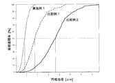
 面積基準平均粒径Dave_Sが0.7μm以下、好ましくは0.6μm以下であるRFeB系合金粉末を用いて、磁場によって配向させた有形体を作製し、該有形体を焼結することにより作製することができる。
The RFeB-based sintered magnet having an area-based average particle diameter D ave_S of crystal grains of 1 μm or less is
Using a RFeB alloy powder having an area-based average particle diameter Dave_S of 0.7 μm or less, preferably 0.6 μm or less, producing a tangible body oriented by a magnetic field and sintering the tangible body Can do.
 このようなRFeB系合金粉末は、原料合金の粗粉にHDDR法(結晶粒微細化処理)を施すことにより結晶粒微細化粗粉粒を作製し、該結晶粒微細化粗粉粒を水素解砕法により解砕した後、ヘリウムガスを用いたジェットミル法で粉砕することにより得ることができる。HDDR法とは、原料合金の粗粉を700~900℃の水素雰囲気中で加熱する(Hydrogenation)ことにより、このRFeB系合金をRH2(Rの水素化物)、Fe2B、Feの3相に分解(Decomposition)し、その温度を維持したまま、雰囲気を水素から真空に切り替えることにより、RH2相から水素を放出(Desorption)させ、これにより原料合金粗粉の各粒内の各相に再結合反応(Recombination)を生じさせるというものである。 Such RFeB-based alloy powder is produced by subjecting the raw material alloy coarse powder to the HDDR method (crystal grain refinement treatment) to produce crystal grain refined coarse powder particles, which are then hydrolyzed. It can be obtained by crushing by a crushing method and then crushing by a jet mill method using helium gas. In the HDDR method, the raw alloy alloy coarse powder is heated in a hydrogen atmosphere at 700-900 ° C (Hydrogenation) to convert this RFeB alloy into three phases of RH 2 (R hydride), Fe 2 B, and Fe. While maintaining the temperature, the atmosphere is switched from hydrogen to vacuum to release hydrogen from the RH 2 phase (desorption), and thereby to each phase in each grain of the raw material alloy coarse powder It causes a recombination reaction (Recombination).
 また、「有形体を作製する」とは、RFeB系合金粉末を用いて、最終製品と同じ又は近い形状を有するもの(これを「有形体」という)を作製することをいう。この有形体は、RFeB系合金粉末を最終製品と同じ又は近い形状にプレス成形した成形体であってもよいし、最終製品と同じ又は近い形状のキャビティを有する容器(モールド)にRFeB系合金粉末を充填した(プレス成形を行わない)ものであってもよい(特許文献2)。有形体がプレス成形を行わずにモールドにRFeB系合金粉末を充填したものである場合には、有形体(すなわち、モールド内のRFeB系合金粉末)に機械的圧力を印加することなく焼結を行うことが望ましい。このように、有形体の作製及び焼結の過程においてRFeB系合金粉末に機械的圧力を印加しないことによって高い保磁力を有し、且つ、粒径の小さいRFeB系合金粉末を容易に取り扱うことができるという点においても高い保磁力を有するRFeB系焼結磁石を得ることができる(特許文献2参照)。 In addition, “manufacturing a tangible body” means that a product having the same shape as or close to that of the final product (referred to as “tangible body”) is produced using RFeB alloy powder. This tangible body may be a molded body obtained by press-forming RFeB-based alloy powder to the same shape as or close to the final product, or RFeB-based alloy powder in a container (mold) having the same or close shape as the final product. (Without press molding) may be used (Patent Document 2). If the tangible body is not press-molded and the mold is filled with RFeB alloy powder, sintering can be performed without applying mechanical pressure to the tangible body (ie, RFeB alloy powder in the mold). It is desirable to do. In this way, RFeB alloy powder having high coercive force and small particle size can be easily handled by not applying mechanical pressure to RFeB alloy powder in the process of preparation and sintering of tangible bodies. An RFeB-based sintered magnet having a high coercive force can also be obtained in that it can be produced (see Patent Document 2).
 本発明により、重希土類元素RHを実質的に含有せず、且つ、温度上昇に伴う保磁力Hcjの減少の割合が小さいという良好な温度特性を有するRFeB系焼結磁石が得られる。そのため、本発明に係るRFeB系焼結磁石は、使用中に温度が上昇する用途に適したものとなる。 According to the present invention, it is possible to obtain an RFeB-based sintered magnet which does not substantially contain heavy rare earth element RH and has a good temperature characteristic that the rate of decrease in coercive force H cj accompanying a temperature rise is small. Therefore, the RFeB-based sintered magnet according to the present invention is suitable for applications in which the temperature rises during use.
本発明に係るRFeB系焼結磁石を製造する方法の一例を説明する図。The figure explaining an example of the method of manufacturing the RFeB type sintered magnet which concerns on this invention. 実施例1及び比較例1、2のRFeB系焼結磁石につき、配向軸に対して垂直な面における顕微鏡像に基づいて、結晶粒の断面積の円相当径から求めた粒度分布を示すグラフ。The graph which shows the particle size distribution calculated | required from the equivalent circle diameter of the cross-sectional area of a crystal grain based on the microscope image in a surface perpendicular | vertical to an orientation axis | shaft about the RFeB type sintered magnet of Example 1 and Comparative Examples 1 and 2. 実施例1及び比較例1、2のRFeB系焼結磁石につき、温度特性値t(T-23)(t(100-23):T=100℃を含む)を求めた結果を示すグラフ。The graph which shows the result of having calculated | required temperature characteristic value t (T-23) (t (100-23) : T = 100 degreeC is included) about the RFeB type sintered magnet of Example 1 and Comparative Examples 1 and 2. FIG. 実施例2及び比較例3~5のRFeB系焼結磁石につき、温度特性値t(T-23)(t(100-23):T=100℃を含む)を求めた結果を示すグラフ。The graph which shows the result of having calculated | required temperature characteristic value t (T-23) (t (100-23) : T = 100 degreeC is included) about Example 2 and the RFeB type sintered magnet of Comparative Examples 3-5 .
 図1~図4を用いて、本発明に係るRFeB系焼結磁石の実施例を説明する。 Examples of the RFeB-based sintered magnet according to the present invention will be described with reference to FIGS.
 まず、図1を用いて、本発明に係るRFeB系焼結磁石を製造する方法の一例を説明する。この製造方法では、HDDR(Hydrogenation Decomposition Disproportionation Recombination)工程(ステップS1)、粉砕工程(ステップS2)、充填工程(ステップS3)、配向工程(ステップS4)及び焼結工程(ステップS5)の5つの工程を行う。原料には、ストリップキャスト(SC)法で作製されたSC合金塊を用いる。SC合金塊は通常、1辺が数mm程度の薄片状のものである。本実施例では、組成が異なる2種類のSC合金塊1及び2を用いた。SC合金塊1及び2の組成を表1に示す。SC合金塊1及び2はいずれも、重希土類元素RHを含有しない。
Figure JPOXMLDOC01-appb-T000004
First, an example of a method for producing an RFeB-based sintered magnet according to the present invention will be described with reference to FIG. In this manufacturing method, there are five processes, namely, HDRD (Hydrogenation Decomposition Disproportionation Recombination) process (step S1), crushing process (step S2), filling process (step S3), orientation process (step S4), and sintering process (step S5). I do. The SC alloy lump produced by the strip cast (SC) method is used as the raw material. The SC alloy lump is usually in the form of a flake having a side of several millimeters. In this example, two types of SC alloy ingots 1 and 2 having different compositions were used. The composition of SC alloy ingots 1 and 2 is shown in Table 1. Neither SC alloy ingot 1 nor 2 contains heavy rare earth element RH .
Figure JPOXMLDOC01-appb-T000004
 HDDR工程では、まず、SC合金塊を水素ガスによる圧力下で熱処理する(Hydrogenation)ことにより、SC合金塊内のR2Fe14B化合物(主相)をRH2、Fe2B、Feの3相に分解する(Disproportionation)。本実施例では、水素ガスの圧力は100kPa、上記熱処理の温度(第1熱処理温度)は950℃とし、熱処理を60分間行った。次いで、第1熱処理温度よりも低い第2熱処理温度に維持した状態で真空にすることにより、RH2相から水素を放出(Desorption)させ、Fe2B相及びFe相と共に再結合反応(Recombination)を生じさせる。本実施例では、第2熱処理温度を800℃として真空を60分間維持した。これにより、面積基準平均粒径Dave_Sが約0.6μmであるRFeB系多結晶体が得られる。 In the HDDR process, the SC alloy lump is first heat treated under hydrogen gas pressure (Hydrogenation) to convert the R 2 Fe 14 B compound (main phase) in the SC alloy lump into 3 RH 2 , Fe 2 B, and Fe. Disproportionation. In this example, the pressure of hydrogen gas was 100 kPa, the temperature of the heat treatment (first heat treatment temperature) was 950 ° C., and the heat treatment was performed for 60 minutes. Next, by making a vacuum while maintaining the second heat treatment temperature lower than the first heat treatment temperature, hydrogen is desorbed from the RH 2 phase, and the recombination reaction (Recombination) together with the Fe 2 B phase and the Fe phase. Give rise to In this example, the second heat treatment temperature was 800 ° C. and the vacuum was maintained for 60 minutes. Thereby, an RFeB-based polycrystalline body having an area-based average particle diameter D ave — S of about 0.6 μm is obtained.
 粉砕工程では、まず、RFeB系多結晶体を外部から加熱することなく水素ガスに晒す。これにより、RFeB系多結晶体は自然に発熱しつつ、水素を吸蔵して脆化する。次に、RFeB系多結晶体を機械的な粉砕機で粗解砕することにより粗粉を得る。この粗粉をヘリウムガス循環式ジェットミル(日本ニューマチック工業株式会社製。「Heジェットミル」と略す。)に導入して粉砕する。Heジェットミルでは、窒素ガスを用いたN2ジェットミルに比べて約3倍速い高速気流が得られるため、原料が高速に加速されて衝突を繰り返し、それにより、N2ジェットミルでは不可能であった、面積基準平均粒径Dave_Sが1μm未満になるまで粉砕することが可能である。これにより、面積基準平均粒径Dave_SがSC合金塊1については約0.6μm、SC合金塊2については約0.67μmという、Dave_Sが0.7μm以下であるRFeB系合金粉末を作製した。 In the pulverization step, first, the RFeB polycrystal is exposed to hydrogen gas without being heated from the outside. Thereby, the RFeB-based polycrystalline body naturally generates heat and absorbs hydrogen to become brittle. Next, coarse powder is obtained by roughly crushing the RFeB-based polycrystal with a mechanical pulverizer. The coarse powder is introduced into a helium gas circulation jet mill (manufactured by Nippon Pneumatic Industry Co., Ltd., abbreviated as “He jet mill”) and pulverized. The He jet mill produces a high-speed airflow that is approximately three times faster than N 2 jet mills using nitrogen gas, so the raw material is accelerated at high speed and repeatedly collides, which is impossible with the N 2 jet mill. It is possible to grind until the area-based average particle diameter D ave — S is less than 1 μm. Thus, an RFeB-based alloy powder having an area-based average particle diameter D ave — S of about 0.6 μm for the SC alloy ingot 1 and about 0.67 μm for the SC alloy ingot 2 and having a D ave — S of 0.7 μm or less was produced.
 充填工程では、最終製品であるRFeB系焼結磁石の形状に対応した空洞を有するモールドにRFeB系合金粉末を所定の充填密度(本実施例では3.6g/cm3)で充填し、次いで、配向工程においてモールド内のRFeB系合金粉末に磁界(本実施例では5Tの直流パルス磁界)を印加することにより合金粉末を配向する。焼結工程では、配向された合金粉末をモールドごと焼結炉に収容し、真空加熱(本実施例では880℃で2時間加熱)することにより焼結させた。これら充填工程、配向工程、及び焼結工程を通して、合金粉末には成形のための機械的圧力は印加しない。以上の工程を経ることにより、本実施例のRFeB系焼結磁石が得られる。以下、SC合金塊1から作製したRFeB系焼結磁石について「実施例1」と呼び、SC合金塊2から作製したRFeB系焼結磁石について「実施例2」と呼ぶ。 In the filling step, a mold having a cavity corresponding to the shape of the final RFeB-based sintered magnet is filled with RFeB-based alloy powder at a predetermined filling density (3.6 g / cm 3 in this example), and then oriented. In the process, the alloy powder is oriented by applying a magnetic field (5T DC pulse magnetic field in this embodiment) to the RFeB alloy powder in the mold. In the sintering step, the oriented alloy powder was placed in a sintering furnace together with the mold, and sintered by vacuum heating (in this example, heating at 880 ° C. for 2 hours). Through these filling process, orientation process, and sintering process, no mechanical pressure for forming is applied to the alloy powder. Through the above steps, the RFeB-based sintered magnet of this example is obtained. Hereinafter, the RFeB-based sintered magnet manufactured from the SC alloy ingot 1 is referred to as “Example 1”, and the RFeB-based sintered magnet manufactured from the SC alloy ingot 2 is referred to as “Example 2”.
 比較例として、本実施例で用いたものと同一ロッドのSC合金塊1及び2を粉砕したRFeB系合金粉末を用いて、RFeB系焼結磁石を作製した。SC合金塊の粉砕は、SC合金塊1については面積基準平均粒径Dave_Sが1.4μm(比較例1)及び3.1μm(比較例2)になるように粉砕し、SC合金塊2についてはDave_Sが1.32μm(比較例3)、3.30μm(比較例4)及び4.10μm(比較例5)になるように行った。これら比較例においては、HDDR工程は行わず、粉砕工程では水素吸蔵法によってSC合金を脆化させた後に粗解砕することによって粗粉を作製した後に、Heジェットミルで粉砕することにより、合金粉末を作製した。充填工程、配向工程、及び焼結工程は、実施例1及び2と同様の方法により行った。 As a comparative example, an RFeB-based sintered magnet was produced using RFeB-based alloy powder obtained by pulverizing SC alloy ingots 1 and 2 of the same rod as used in this example. The SC alloy lump was pulverized so that the area-based average particle diameter D ave — S for SC alloy lump 1 was 1.4 μm (Comparative Example 1) and 3.1 μm (Comparative Example 2). The ave_S was adjusted to 1.32 μm (Comparative Example 3), 3.30 μm (Comparative Example 4), and 4.10 μm (Comparative Example 5). In these comparative examples, the HDDR process is not performed, and in the pulverization process, the SC alloy is embrittled by embrittlement and then coarsely pulverized, and then pulverized with a He jet mill. A powder was prepared. The filling step, the alignment step, and the sintering step were performed in the same manner as in Examples 1 and 2.
 実施例1及び比較例1、2のRFeB系焼結磁石につき、配向軸に対して垂直な面における顕微鏡像に基づいて、結晶粒の断面積の円相当径から求めた粒度分布を図2のグラフに示す。このグラフより面積基準平均粒径Dave_Sを求めると、実施例1では0.83μm、比較例1では1.78μm、比較例2では3.65μmとなった。 For the RFeB sintered magnets of Example 1 and Comparative Examples 1 and 2, the particle size distribution obtained from the equivalent circle diameter of the cross-sectional area of the crystal grain based on the microscopic image in the plane perpendicular to the orientation axis is shown in FIG. Shown in the graph. When the area-based average particle diameter D ave — S was determined from this graph, it was 0.83 μm in Example 1, 1.78 μm in Comparative Example 1, and 3.65 μm in Comparative Example 2.
 これら実施例1及び比較例1、2について得られた保磁力Hcjのデータに基づき、T=60℃、100℃、140℃及び180℃における温度特性値t(T-23)を求めた結果を図3のグラフに示す。このグラフ中の縦の破線上にあるデータが、本発明で規定するT=100℃における温度特性値t(100-23)である。実施例1及び比較例1、2におけるデータの大小関係(すなわち良否)は、保磁力Hcjそのものは温度によって相違するが、温度特性値t(T-23)はTに依らずに同様である。そして、温度特性値t(100-23)は、実施例1では-0.53という、比較例1における-0.66、比較例2における-0.73、及び非特許文献1における最高値である-0.58よりも大きい値を有する。このように、実施例1のRFeB系焼結磁石は、比較例1及び2、並びに非特許文献1に記載のRFeB系焼結磁石よりも良好な温度特性を有している。 Results of obtaining temperature characteristic values t (T-23) at T = 60 ° C., 100 ° C., 140 ° C. and 180 ° C. based on the coercivity H cj data obtained for Example 1 and Comparative Examples 1 and 2 Is shown in the graph of FIG. The data on the vertical broken line in this graph is the temperature characteristic value t (100-23) at T = 100 ° C. defined in the present invention. The magnitude relationship (ie, pass / fail) of the data in Example 1 and Comparative Examples 1 and 2 is that the coercive force H cj itself differs depending on the temperature, but the temperature characteristic value t (T-23) is the same regardless of T. . The temperature characteristic value t (100-23) is -0.53 in Example 1, -0.66 in Comparative Example 1, -0.73 in Comparative Example 2, and -0.58 which is the highest value in Non-Patent Document 1. Has a value. As described above, the RFeB-based sintered magnet of Example 1 has better temperature characteristics than the RFeB-based sintered magnets described in Comparative Examples 1 and 2 and Non-Patent Document 1.
 同様の方法により、実施例2及び比較例3~5について温度特性値t(T-23)を求めた結果を図4のグラフに示す。温度特性値t(100-23)は、実施例2において-0.48という、比較例3~5における値(-0.66~-0.60)及び非特許文献1における最高値である-0.58よりも大きい値を有する。また、この実施例2の温度特性値t(100-23)の値は、実施例1における値よりも大きい。これは、実施例2では、Prの含有量が0.07質量%という、実施例1(4.15質量%)よりも低い値であることによる。 The graph of FIG. 4 shows the results of obtaining the temperature characteristic value t (T-23) for Example 2 and Comparative Examples 3 to 5 by the same method. The temperature characteristic value t (100-23) is −0.48 in Example 2, which is larger than the values (−0.66 to −0.60) in Comparative Examples 3 to 5 and −0.58 which is the highest value in Non-Patent Document 1. Have. Further, the value of the temperature characteristic value t (100-23) of the second embodiment is larger than the value in the first embodiment. This is because in Example 2, the Pr content was 0.07% by mass, which was lower than Example 1 (4.15% by mass).

Claims (5)

  1.  Fe及びBに加え、希土類元素RとしてNd及びPrのうちの少なくとも1種を含有する一方、Dy, Tb及びHoを含有しないRFeB系焼結磁石であって、
     温度が23℃であるときの保磁力の値Hcj(23)及び温度が100℃であるときの保磁力の値Hcj(100)を用いて
    Figure JPOXMLDOC01-appb-M000001

    と定義される温度特性値t(100-23)が-0.58<t(100-23)<0であることを特徴とするRFeB系焼結磁石。
    An RFeB-based sintered magnet that contains at least one of Nd and Pr as the rare earth element R in addition to Fe and B, but does not contain Dy, Tb, and Ho,
    Using the coercive force value H cj (23) when the temperature is 23 ° C. and the coercive force value H cj (100) when the temperature is 100 ° C.
    Figure JPOXMLDOC01-appb-M000001

    An RFeB sintered magnet characterized in that a temperature characteristic value t (100-23) defined as follows: -0.58 <t (100-23) <0.
  2.  温度特性値t(100-23)が-0.58<t(100-23)≦-0.48であることを特徴とする請求項1に記載のRFeB系焼結磁石。 2. The RFeB-based sintered magnet according to claim 1, wherein a temperature characteristic value t (100-23) is −0.58 <t (100-23) ≦ −0.48.
  3.  断面の顕微鏡画像から求められる、結晶粒の円相当径による面積基準平均粒径が1μm以下であることを特徴とする請求項1又は2に記載のRFeB系焼結磁石。 3. The RFeB-based sintered magnet according to claim 1 or 2, wherein an area-based average particle diameter based on a circle-equivalent diameter of crystal grains obtained from a microscopic image of a cross section is 1 μm or less.
  4.  請求項1~3のいずれかに記載のRFeB系焼結磁石を製造する方法であって、
     面積基準平均粒径が0.7μm以下であるRFeB系合金粉末を用いて、磁場によって配向させた有形体を作製し、該有形体を焼結することを特徴とするRFeB系焼結磁石の製造方法。
    A method for producing an RFeB-based sintered magnet according to any one of claims 1 to 3,
    A method for producing an RFeB-based sintered magnet, comprising producing a tangible body oriented by a magnetic field using an RFeB-based alloy powder having an area-based average particle size of 0.7 μm or less, and sintering the tangible body .
  5.  原料合金の粗粉にHDDR法を施すことにより結晶粒微細化粗粉粒を作製し、該結晶粒微細化粗粉粒を水素解砕法により解砕した後、ヘリウムガスを用いたジェットミル法で粉砕することにより前記RFeB系合金粉末を作製することを特徴とする請求項4に記載のRFeB系焼結磁石の製造方法。 By applying the HDDR method to the raw alloy coarse powder, the crystal grain refined coarse powder is produced, and the crystal grain refined coarse powder is crushed by the hydrogen crushing method, and then by a jet mill method using helium gas. The method for producing an RFeB-based sintered magnet according to claim 4, wherein the RFeB-based alloy powder is produced by pulverization.
PCT/JP2015/073064 2014-08-18 2015-08-18 RFeB-BASED SINTERED MAGNET WO2016027791A1 (en)

Priority Applications (4)

Application Number Priority Date Filing Date Title
EP15833977.0A EP3185252A4 (en) 2014-08-18 2015-08-18 RFeB-BASED SINTERED MAGNET
CN201580044078.6A CN106575556A (en) 2014-08-18 2015-08-18 Rfeb-based sintered magnet
US15/503,814 US20170278604A1 (en) 2014-08-18 2015-08-18 RFeB SYSTEM SINTERED MAGNET
JP2016544207A JPWO2016027791A1 (en) 2014-08-18 2015-08-18 RFeB-based sintered magnet

Applications Claiming Priority (2)

Application Number Priority Date Filing Date Title
JP2014165953 2014-08-18
JP2014-165953 2014-08-18

Publications (1)

Publication Number Publication Date
WO2016027791A1 true WO2016027791A1 (en) 2016-02-25

Family

ID=55350735

Family Applications (1)

Application Number Title Priority Date Filing Date
PCT/JP2015/073064 WO2016027791A1 (en) 2014-08-18 2015-08-18 RFeB-BASED SINTERED MAGNET

Country Status (5)

Country Link
US (1) US20170278604A1 (en)
EP (1) EP3185252A4 (en)
JP (1) JPWO2016027791A1 (en)
CN (1) CN106575556A (en)
WO (1) WO2016027791A1 (en)

Cited By (1)

* Cited by examiner, † Cited by third party
Publication number Priority date Publication date Assignee Title
JP2018022834A (en) * 2016-08-05 2018-02-08 Tdk株式会社 R-T-B based sintered magnet

Families Citing this family (1)

* Cited by examiner, † Cited by third party
Publication number Priority date Publication date Assignee Title
JP6848736B2 (en) * 2016-07-15 2021-03-24 Tdk株式会社 RTB series rare earth permanent magnet

Citations (5)

* Cited by examiner, † Cited by third party
Publication number Priority date Publication date Assignee Title
WO2009122709A1 (en) * 2008-03-31 2009-10-08 日立金属株式会社 R-t-b-type sintered magnet and method for production thereof
JP2010182827A (en) * 2009-02-04 2010-08-19 Toyota Motor Corp Production method of high-coercive force magnet
JP2010219499A (en) * 2009-02-18 2010-09-30 Tdk Corp R-t-b based rare earth sintered magnet and method for manufacturing the same
JP2011216720A (en) * 2010-03-31 2011-10-27 Nitto Denko Corp Permanent magnet and method for manufacturing the same
WO2014142137A1 (en) * 2013-03-12 2014-09-18 インターメタリックス株式会社 METHOD FOR PRODUCING RFeB SINTERED MAGNET AND RFeB SINTERED MAGNET PRODUCED THEREBY

Family Cites Families (4)

* Cited by examiner, † Cited by third party
Publication number Priority date Publication date Assignee Title
JP3423965B2 (en) * 1992-09-02 2003-07-07 住友特殊金属株式会社 Method for producing anisotropic rare earth alloy powder for permanent magnet
CN102103917B (en) * 2009-12-22 2013-04-17 北京有色金属研究总院 Neodymium iron boron magnet, preparation method and device applying same
CN102214508B (en) * 2010-04-02 2014-03-12 烟台首钢磁性材料股份有限公司 R-T-B-M-A rare earth permanent magnet and manufacturing method thereof
JP5757234B2 (en) * 2011-12-27 2015-07-29 トヨタ自動車株式会社 Method for producing quench ribbon for rare earth magnet

Patent Citations (5)

* Cited by examiner, † Cited by third party
Publication number Priority date Publication date Assignee Title
WO2009122709A1 (en) * 2008-03-31 2009-10-08 日立金属株式会社 R-t-b-type sintered magnet and method for production thereof
JP2010182827A (en) * 2009-02-04 2010-08-19 Toyota Motor Corp Production method of high-coercive force magnet
JP2010219499A (en) * 2009-02-18 2010-09-30 Tdk Corp R-t-b based rare earth sintered magnet and method for manufacturing the same
JP2011216720A (en) * 2010-03-31 2011-10-27 Nitto Denko Corp Permanent magnet and method for manufacturing the same
WO2014142137A1 (en) * 2013-03-12 2014-09-18 インターメタリックス株式会社 METHOD FOR PRODUCING RFeB SINTERED MAGNET AND RFeB SINTERED MAGNET PRODUCED THEREBY

Non-Patent Citations (1)

* Cited by examiner, † Cited by third party
Title
See also references of EP3185252A4 *

Cited By (1)

* Cited by examiner, † Cited by third party
Publication number Priority date Publication date Assignee Title
JP2018022834A (en) * 2016-08-05 2018-02-08 Tdk株式会社 R-T-B based sintered magnet

Also Published As

Publication number Publication date
JPWO2016027791A1 (en) 2017-06-22
EP3185252A1 (en) 2017-06-28
US20170278604A1 (en) 2017-09-28
EP3185252A4 (en) 2017-08-30
CN106575556A (en) 2017-04-19

Similar Documents

Publication Publication Date Title
TWI575081B (en) Rare earth sintered magnet and making method
JP6366666B2 (en) Method for producing sintered Nd-Fe-B magnetic body containing no heavy rare earth element
JP6177877B2 (en) Method for manufacturing RFeB-based sintered magnet and RFeB-based sintered magnet manufactured thereby
JP5856953B2 (en) Rare earth permanent magnet manufacturing method and rare earth permanent magnet
JP6488976B2 (en) R-T-B sintered magnet
JP5120710B2 (en) RL-RH-T-Mn-B sintered magnet
WO2012002059A1 (en) R-t-b type rare earth permanent magnet, motor, automobile, power generator, and wind power generation system
JP6094612B2 (en) Method for producing RTB-based sintered magnet
WO2010113371A1 (en) Alloy material for r-t-b-type rare-earth permanent magnet, process for production of r-t-b-type rare-earth permanent magnet, and motor
CN106710765A (en) High-coercivity sintered-neodymium-iron-boron magnetic body and preparing method thereof
CN110537232B (en) Permanent magnet and rotating electrical machine
JP6037093B1 (en) Method for producing RTB-based sintered magnet
JPWO2016111346A1 (en) Method for producing RFeB-based sintered magnet
JP6613730B2 (en) Rare earth magnet manufacturing method
CN112119475B (en) Method for producing rare earth sintered permanent magnet
CN110024057B (en) Rare earth permanent magnet
WO2016027791A1 (en) RFeB-BASED SINTERED MAGNET
JP6691666B2 (en) Method for manufacturing RTB magnet
CN111724955B (en) R-T-B permanent magnet
JP6624455B2 (en) Method for producing RTB based sintered magnet
JP5686212B1 (en) R-T-B permanent magnet
JP2023081336A (en) Rare earth sintered neodymium-iron-boron magnet, method of manufacturing the same, and use of hydrogenated praseodymium
Lv et al. Coercivity enhancement in Dy-free HDDR Nd-Fe-B powders by the grain boundary diffusion of Zn
JP6691667B2 (en) Method for manufacturing RTB magnet
Sreenivasulu et al. Spark plasma sintered Sm2Co17–FeCo nanocomposite permanent magnets synthesized by high energy ball milling

Legal Events

Date Code Title Description
121 Ep: the epo has been informed by wipo that ep was designated in this application

Ref document number: 15833977

Country of ref document: EP

Kind code of ref document: A1

ENP Entry into the national phase

Ref document number: 2016544207

Country of ref document: JP

Kind code of ref document: A

REEP Request for entry into the european phase

Ref document number: 2015833977

Country of ref document: EP

WWE Wipo information: entry into national phase

Ref document number: 15503814

Country of ref document: US

Ref document number: 2015833977

Country of ref document: EP

NENP Non-entry into the national phase

Ref country code: DE