WO2016027490A2 - 血管剥離方法 - Google Patents
血管剥離方法 Download PDFInfo
- Publication number
- WO2016027490A2 WO2016027490A2 PCT/JP2015/058097 JP2015058097W WO2016027490A2 WO 2016027490 A2 WO2016027490 A2 WO 2016027490A2 JP 2015058097 W JP2015058097 W JP 2015058097W WO 2016027490 A2 WO2016027490 A2 WO 2016027490A2
- Authority
- WO
- WIPO (PCT)
- Prior art keywords
- blood vessel
- movable
- guide
- saphenous vein
- peeling
- Prior art date
- Legal status (The legal status is an assumption and is not a legal conclusion. Google has not performed a legal analysis and makes no representation as to the accuracy of the status listed.)
- Ceased
Links
Images












Classifications
-
- A—HUMAN NECESSITIES
- A61—MEDICAL OR VETERINARY SCIENCE; HYGIENE
- A61B—DIAGNOSIS; SURGERY; IDENTIFICATION
- A61B17/00—Surgical instruments, devices or methods
Definitions
- the present invention relates to a blood vessel peeling method.
- Arterial grafts typified by the internal thoracic artery, gastroepiploic artery, radial artery, and venous grafts typified by the great saphenous vein are used as bypass blood vessels when performing vascular bypass surgery (coronary artery bypass surgery: CABG) in the heart. It is widely known to use. At present, it has been reported that arterial grafts (particularly internal thoracic arteries) have a higher long-term patency rate than venous grafts. Thus, although it is a vein graft that is said to be inferior in the long-term patency rate, in recent years, the vein graft is collected in a state covered with surrounding tissues (fat, connective tissue, etc.) and covered with the tissue.
- a guide wire (support member 50) is inserted into a blood vessel to be collected as a bypass blood vessel, and the tubular member (portion 40) is pushed forward while being guided by the guide wire. It can be collected while covered with tissue.
- the device described in Patent Document 1 has a problem that the inner wall of the blood vessel may be damaged by the guide wire, and the workability of blood vessel collection is poor.
- An object of the present invention is to provide a blood vessel peeling method excellent in workability of blood vessel collection (blood vessel peeling).
- a blood vessel peeling method comprising: a second step of peeling in a state.
- the guide portion in the first step, is disposed along the blood vessel, so that damage to the blood vessel can be suppressed.
- contact between the movable portion and the blood vessel is suppressed by moving the movable portion while guiding the movable portion with the guide portion.
- FIG. 1 is a perspective view showing a blood vessel peeling device used in the blood vessel peeling method according to the first embodiment of the present invention.
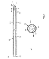
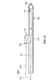
- FIG. 2 is a cross-sectional view showing a guide portion of the blood vessel peeling device shown in FIG.
- FIG. 3 is a plan view showing a movable part of the blood vessel peeling device shown in FIG.
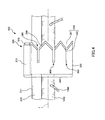
- FIG. 4 is a side view showing the movable part shown in FIG.
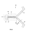
- FIG. 5 is a side view illustrating a processing unit included in the movable unit illustrated in FIG. 3.
- FIG. 6 is a side view showing a modification of the movable part shown in FIG.
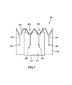
- FIG. 7 is a view showing a modification of the movable part of the blood vessel peeling device shown in FIG. FIG.
- FIG. 8 is a cross-sectional view showing an operation unit of the blood vessel peeling device shown in FIG.
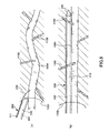
- FIG. 9 is a diagram for explaining a blood vessel peeling method using the blood vessel peeling device shown in FIG.
- FIG. 10 is a diagram for explaining a blood vessel peeling method using the blood vessel peeling device shown in FIG.
- FIG. 11 is a diagram for explaining a blood vessel peeling method using the blood vessel peeling device shown in FIG.
- FIG. 12 is a diagram for explaining a blood vessel peeling method using the blood vessel peeling device shown in FIG.
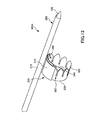
- FIG. 13 is a perspective view showing a blood vessel peeling device used in the blood vessel peeling method according to the second embodiment of the present invention.
- FIG. 10 is a diagram for explaining a blood vessel peeling method using the blood vessel peeling device shown in FIG.
- FIG. 11 is a diagram for explaining a blood vessel peeling method using the blood vessel peeling device shown in FIG.
- FIG. 12 is a diagram for explaining a blood vessel peeling method
- FIG. 14 is a diagram for explaining a blood vessel peeling method using the blood vessel peeling device shown in FIG.
- FIG. 15 is a cross-sectional view showing a blood vessel peeling device used in a blood vessel peeling method according to a third embodiment of the present invention.
- FIG. 16 is sectional drawing which shows the blood vessel peeling device used with the blood vessel peeling method which concerns on 4th Embodiment of this invention.
- FIG. 17 is a cross-sectional view showing a blood vessel peeling device used in a blood vessel peeling method according to a fifth embodiment of the present invention.
- FIG. 18 is a diagram illustrating a blood vessel peeling method using the blood vessel peeling device shown in FIG. FIG.
- FIG. 19 is a cross-sectional view showing a modified example of the blood vessel peeling device shown in FIG.
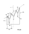
- FIG. 20 is a side view showing a movable part included in a blood vessel peeling device used in the blood vessel peeling method according to the sixth embodiment of the present invention.
- FIG. 21 is a side view and a cross-sectional view showing a movable part included in a blood vessel peeling device used in a blood vessel peeling method according to a seventh embodiment of the present invention.
- FIG. 22 is a cross-sectional view showing a blood vessel peeling device used in the blood vessel peeling method according to the eighth embodiment of the present invention.
- FIG. 20 is a side view showing a movable part included in a blood vessel peeling device used in the blood vessel peeling method according to the sixth embodiment of the present invention.
- FIG. 21 is a side view and a cross-sectional view showing a movable part included in a blood vessel peeling device used in a blood vessel peeling method according to
- FIG. 23 is a cross-sectional view showing a blood vessel peeling device used in a blood vessel peeling method according to a ninth embodiment of the present invention.
- FIG. 24 is a plan view and a side view of the blood vessel peeling device shown in FIG.
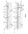
- FIG. 25 is a cross-sectional view showing a movable part included in a blood vessel peeling device used in a blood vessel peeling method according to a tenth embodiment of the present invention.
- FIG. 26 is a diagram for explaining a blood vessel peeling method using the blood vessel peeling device shown in FIG.
- FIG. 27 is a plan view showing a blood vessel peeling device used in the blood vessel peeling method according to the eleventh embodiment of the present invention.
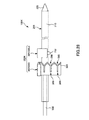
- FIG. 28 is a side view showing a blood vessel peeling device used in a blood vessel peeling method according to a twelfth embodiment of the present invention.
- FIG. 1 is a perspective view showing a blood vessel peeling device used in the blood vessel peeling method according to the first embodiment of the present invention.
- FIG. 2 is a cross-sectional view showing a guide portion of the blood vessel peeling device shown in FIG.
- FIG. 3 is a plan view showing a movable part of the blood vessel peeling device shown in FIG.
- FIG. 4 is a side view showing the movable part shown in FIG.
- FIG. 5 is a side view illustrating a processing unit included in the movable unit illustrated in FIG. 3.
- FIG. 6 is a side view showing a modification of the movable part shown in FIG.
- FIG. 7 is a view showing a modification of the movable part of the blood vessel peeling device shown in FIG.
- FIG. 1 is a perspective view showing a blood vessel peeling device used in the blood vessel peeling method according to the first embodiment of the present invention.
- FIG. 2 is a cross-sectional view showing a guide portion of the blood vessel peeling device
- FIG. 8 is a cross-sectional view showing an operation unit of the blood vessel peeling device shown in FIG. 9 to 12 are views for explaining a blood vessel peeling method using the blood vessel peeling device shown in FIG.
- FIG. 2B is a cross-sectional view taken along line AA in FIG.
- the right side in FIG. 1 is also referred to as “tip” and the left side is also referred to as “base end”.
- a blood vessel peeling device 100 shown in FIG. 1 is a device used to collect a blood vessel used as a bypass blood vessel when performing blood vessel bypass surgery (coronary artery bypass surgery: CABG). It can be collected in a state covered with tissue.
- the blood vessel collected using the blood vessel peeling device 100 is not particularly limited as long as it is a blood vessel that can be used as a bypass blood vessel.
- the blood vessel to be collected is preferably the great saphenous vein among them.
- the blood vessel peeling device 100 As described above, blood vessels can be collected in a state covered with surrounding tissue. Therefore, it is considered that the long-term patency after surgery is increased by collecting the large saphenous vein using the blood vessel peeling device 100 and using it as a bypass blood vessel. Therefore, in the following, an example in which the large saphenous vein is collected using the blood vessel peeling device 100 will be described as a representative.
- the blood vessel peeling device 100 includes a guide unit 200 disposed along the outer wall of the great saphenous vein 1000, an imaging device 400 inserted into the guide unit 200, and the guide unit 200.
- a movable unit 300 that moves in the living body while being guided, and an operation unit 500 that moves the movable unit 300 are provided.
- each of these units will be sequentially described in detail.
- the guide part 200 includes a main body part 210 and a peeling part (observation part) 220 provided at the tip of the main body part 210.
- the main body 210 has a tubular shape extending in a straight line.
- the main body 210 is provided with a slit-shaped rail 211 extending in the axial direction.
- the rail 211 functions as a guide unit that guides the movement of the movable unit 300.
- the rail 211 is open to the base end of the main body 210, and the movable part 300 can be connected from this open portion (that is, the base end of the main body 210). Since the proximal end of the guide part 200 is exposed from the living body as will be described later in the “blood vessel peeling method”, the connection is made possible by connecting the movable part 300 from the proximal end side of the guide part 200. Can be done more easily.
- the cross-sectional shape of the main body 210 is not limited to a circle as in the present embodiment, and may be, for example, a flat shape crushed in the alignment direction with the great saphenous vein 1000.
- the rail 211 may not be slit-shaped as long as it can guide the movement of the movable part 300, and may be a groove of a ridge or a protrusion of a ridge.
- the peeling part 220 is tapered toward the tip of the guide part 200 and has a conical shape. Moreover, the peeling part 220 is substantially colorless and transparent, and has light transmittance. Such an exfoliation part 220 has a function of exfoliating tissues (fat, connective tissue, etc.) and an observation of observing the in vivo (large saphenous vein 1000 and its surroundings) when the guide part 200 is advanced in the living body. And function as a part.
- a shape of the peeling part 220 it is not limited to a cone shape like this embodiment, For example, the duckbill shape tapering so that a front-end
- the peeling portion 220 is not limited to being colorless and transparent as long as it has light transparency, and may be colored red, blue, green, or the like.
- the imaging device 400 includes a long main body 410, and an imaging unit that images the front of the guide unit 200 and an illumination unit 420 that emits illumination light at the tip of the main body unit 410.
- the imaging unit 430 includes, for example, an objective lens system provided at the distal end portion of the main body 410 and an imaging device (for example, a solid-state imaging device such as a CMOS image sensor or a CCD sensor) disposed to face the objective lens system. I have.
- Such an imaging device 400 can be inserted into the above-described guide unit 200 as shown in FIG. Thus, by inserting the imaging device 400 into the guide part 200, the imaging device 400 can observe the front of the guide part 200 via the peeling part 220.
- the movable unit 300 moves in the living body to separate the large saphenous vein 1000 while it is covered with the surrounding tissue (fat, connective tissue, etc.) 1200 and branch off from the large saphenous vein 1000.
- the branch blood vessel 1100 that is present is cut and stopped.
- Such a movable part 300 is detachable from the guide part 200, and as shown in FIGS. 3 and 4, a connector 310 connected to the rail 211 of the guide part 200 and a mounting part 320 attached to the connector 310. And a peeling unit 350 and a processing unit 360.
- the connector 310 has a base portion 311 that is curved in a substantially arc shape and a connection portion 312 that slidably connects the base portion 311 to the rail 211. Further, grooves 311 a and 311 b for mounting the mounting portion 320 are provided at both ends in the circumferential direction of the base portion 311.
- the mounting portion 320 has a slit (321) extending in the axial direction and has a cylindrical shape (tubular shape) having a substantially C-shaped cross-sectional shape.
- Such a mounting portion 320 is mounted to the connector 310 by engaging both end portions in the circumferential direction with the slit 321 between the grooves 311 a and 311 b of the connector 310.
- the guide part 200 is located inside the cyclic
- the inner diameter of the annular portion 340 is larger than the outer diameter of the large saphenous vein 1000, and when in use, the large saphenous vein is located inside the annular portion 340 and on the central axis J as shown in FIG. 1000 is located.
- the width of the slit 321 is not particularly limited, but is preferably larger than the outer diameter of the large saphenous vein 1000.
- the attachment part 320 can be attached to the connector 310 in a non-contact manner (or a light contact without damage) with the great saphenous vein 1000. Therefore, damage to the great saphenous vein 1000 when attaching the attachment part 320 to the connector 310 can be suppressed.
- the width of the slit 321 is not limited to this, and may be smaller than the outer diameter of the large saphenous vein 1000. In this case, for example, the attachment part 320 can be attached to the connector 310 without contact with the large saphenous vein 1000 by expanding the deformation of the attachment part 320 and expanding the slit 321.
- the annular portion 340 has a groove portion 390 that opens to the tip portion thereof, and a plurality of the groove portions 390 are arranged side by side in the circumferential direction of the annular portion 340.
- Each groove portion 390 is connected to a tapered blood vessel guide groove portion (first groove portion) 391 whose width gradually decreases toward the proximal end side and a proximal end portion of the blood vessel guide groove portion 391, and the straight width is substantially constant.
- the blood vessel guide groove portion 391 is a groove portion that guides the branch blood vessel 1100 that contacts when the movable portion 300 is pushed in the living body to the blood vessel processing groove portion 392, and has a tapered shape to smoothly perform this guidance.
- the branch blood vessel 1100 can be smoothly guided to any one of the blood vessel guide groove portions 391.
- the blood vessel processing groove 392 is a groove for cutting and stopping the branch blood vessel 1100 guided by the blood vessel guide groove 391, and each blood vessel processing groove 392 is provided with a processing unit 360.
- the processing unit 360 has a bipolar structure having a pair of electrodes 361 and 362 that can generate an electric field in the blood vessel processing groove 392.
- the electrode 361 is provided at the proximal end (bottom) of the vascular treatment groove 392, and the electrodes 362 are provided on both sides in the width direction of the vascular treatment groove 392.
- the branch blood vessel 1100 guided by the blood vessel processing groove 392 is heated and cut, and is thermally coagulated to stop hemostasis.
- the tip 361 ′ of the electrode 361 is preferably sharp enough to cut the branch blood vessel 1100.
- the branch blood vessel 1100 can be thermally coagulated (hemostatic) by an electric field generated at least between the electrodes 361 and 362, the branch blood vessel can be physically cut by the electrode 361. Therefore, the certainty of processing by the processing unit 360 is improved.
- the width W of the blood vessel processing groove 392 is not particularly limited, but is preferably narrower than the outer diameter of the branch blood vessel 1100 as shown in FIG. Thereby, since the branch blood vessel 1100 can be crushed in the blood vessel processing groove 392, the processing (cutting / hemostasis) by the processing unit 360 can be performed more reliably.
- the annular part 340 is provided with a peeling part 350 for peeling the tissue around the great saphenous vein 1000.
- the peeling portion 350 is provided along the blood vessel guide groove portion 391 at the distal end portion of the annular portion 340.
- the exfoliation part 350 has a function of exfoliating the tissue around the large saphenous vein 1000 when the movable part 300 is pushed forward in the living body.
- Such an exfoliation part 350 preferably has such a sharpness that it can exfoliate the tissue without cutting the branch blood vessel 1100. Thereby, since the cutting
- the shape of the blood vessel guide groove 391 is not limited to the shape of the present embodiment.
- the shape may be gradually reduced toward the side. By setting it as such a shape, since the peeling part 350 is rounded, the branch blood vessel 1100 becomes difficult to cut
- the adjacent groove parts 390 may be spaced apart.
- the groove portion 390 and the processing portion 360 are not provided in the base portion 311, but for example, as shown in FIG. 7, the groove portion 390 and the processing portion 360 are also provided in the base portion 311 in the same manner as the mounting portion 320. It may be provided. Thereby, the groove part 390 and the process part 360 are arrange
- the operation unit 500 has a rod shape and can be inserted into the guide unit 200. Therefore, the movable unit 300 can be moved by inserting the operation unit 500 into the guide unit 200 and pressing the connector 310 with the tip thereof.
- the operation part 500 can be fixed to the connector 310 by means such as fitting or screwing. Thereby, the movable part 300 can be pushed and pulled by the operation part 500.
- the blood vessel peeling method (blood vessel sampling method) using the blood vessel peeling device 100 includes a first step of inserting the guide portion 200 along the outer wall of the great saphenous vein 1000, and a movable portion 300 connected to the guide portion 200. A second step of peeling the large saphenous vein 1000 while being covered with the surrounding tissue 1200 by moving, a third step of cutting after ligating the large saphenous vein 1000, and surrounding the large saphenous vein 1000 And a fourth step of extraction in a state of being covered with the tissue 1200.
- the connector 310 is connected to the rail 211 from the base end of the guide part 200 as shown in FIG.
- the attachment part 320 is attached to the connector 310 so that the saphenous vein 1000 is located.
- the annular portion 340 is formed, and the large saphenous vein 1000 is disposed in the annular portion 340.
- the large saphenous vein 1000 is located on the central axis J of the annular portion 340.
- the connector 310 may be connected to the guide unit 200 without removing the imaging device 400 from the guide unit 200.
- the connector 310 is connected to the rail 211 from the proximal end of the guide portion 200.
- the connection can be smoothly performed.
- the movable part 300 is detachable from the guide part 200, and the movable part 300 is connected to the guide part 200 in the second step, whereby the first step is performed in the state where the movable part 300 is not connected. Can be used. Therefore, the movable part 300 does not get in the way and the first step can be performed more smoothly.
- the movable unit 300 is pushed into the living body using the operation unit 500, and the living body is advanced along the rail 211 (while being guided by the guide unit 200).
- the tissue 1200 around the great saphenous vein 1000 is peeled off by the peeling part 350, and the branch blood vessel 1100 is guided to the processing part 360 by the groove part 390, and is cut and stopped by the processing part 360.
- the large saphenous vein 1000 is peeled off while being covered with the surrounding tissue 1200.
- the movable unit 300 and the large saphenous vein 1000 are located. Contact with the vein 1000 is prevented, and the great saphenous vein 1000 can be positioned approximately in the center of the exfoliated tissue 1200. Therefore, the greater saphenous vein 1000 can be exfoliated while being covered with the surrounding tissue 1200 more accurately and without bias.
- the thickness t1 of the tissue 1200 exfoliated with the great saphenous vein 1000 and located around the great saphenous vein 1000 is not particularly limited, but is preferably about 0.1 mm to 10 mm, and about 1 mm to 8 mm. More preferably, it is about 3 mm to 5 mm.
- peeling work the operation of moving the movable unit 300 and peeling off the large saphenous vein 1000 while being covered with the surrounding tissue 1200 is also referred to as “peeling work”.
- the large saphenous vein 1000 is cut at the proximal-side planned cut portion 1001 and the distal-side planned cut portion 1002.
- two sites before and after the proximal end side cut planned portion 1001 of the large saphenous vein 1000 are ligated and the front end side cut planned portion 1002 is sandwiched. Ligate the two places before and after.
- the ligation on the tip side cut planned portion 1002 side can be performed through the incision portion 1400 by incising the vicinity of the tip side cut planned portion 1002.
- FIG. 11 (b) the large saphenous vein 1000 is cut at the base end side planned cut portion 1001 and the distal end side cut planned portion 1002.
- the large saphenous vein 1000 can be collected (extracted) while being covered with the surrounding tissue 1200.
- the great saphenous vein 1000 collected in such a state may be a bypass blood vessel having a long-term patency rate superior to that of the great saphenous vein not covered with the tissue 1200. This is believed to be due to the following reasons.
- the great saphenous vein 1000 is used as an arterial bypass blood vessel, but the artery has higher blood pressure (internal pressure received by blood) than the vein. Therefore, if a large saphenous vein that is not covered with the tissue 1200 is used as a bypass blood vessel, the large saphenous vein may expand without being able to withstand blood pressure, and blood flow may be reduced. In addition, the blood vessel wall may become thickened in the process of remodeling (structural modification) or tissue damage repair. Such thickening of the blood vessel wall is considered to affect the progress of arteriosclerosis. For these reasons, if a large saphenous vein that is not covered with the tissue 1200 is used as a bypass blood vessel, it may lead to blood vessel occlusion in the long term.
- the tissue 1200 suppresses the expansion of the large saphenous vein 1000 and suppresses the bending of the great saphenous vein 1000 and the like. It can be expected to be effective. Therefore, there is a possibility that a decrease in blood flow as described above can be suppressed.
- damage to the great saphenous vein 1000 specifically, damage to endothelial cells, smooth muscle, nutrient blood vessels (small blood vessel network), and the like is reduced. Therefore, there is a possibility that the above-described thickening of the blood vessel wall can be suppressed.
- the large saphenous vein 1000 can be removed smoothly and accurately in a state covered with the surrounding tissue 1200. More specifically, in the first step, the guide portion 200 is disposed along the outer wall of the great saphenous vein 1000, whereby damage to the great saphenous vein 1000 can be suppressed. Furthermore, in the second step, since the movable part 300 is moved while being guided by the guide part 200, the contact between the movable part 300 and the great saphenous vein 1000 is suppressed. Therefore, according to the above-described method, the large saphenous vein 1000 can be peeled while being covered with the surrounding tissue 1200 while suppressing damage to the large saphenous vein 1000.
- the second step can be performed more smoothly and accurately. Further, since the great saphenous vein 1000 is not cut until the second step is completed, blood can be passed through the great saphenous vein 1000 as long as possible. Therefore, the great saphenous vein 1000 having a shorter ischemic state and less damage can be collected.
- the large saphenous vein 1000 is collected (exfoliated) in a state where the entire circumference is covered with the tissue 1200, but is not limited to the one where the entire circumference is covered with the tissue 1200, It suffices if the great saphenous vein 1000 can be collected (exfoliated) in a state where at least a part of its circumference is covered with the tissue 1200.
- FIG. 13 is a perspective view showing a blood vessel peeling device used in the blood vessel peeling method according to the second embodiment of the present invention.
- FIG. 14 is a diagram for explaining a blood vessel peeling method using the blood vessel peeling device shown in FIG.
- This embodiment is mainly the same as the first embodiment described above except that the configuration of the operation unit is different.
- the guide unit 200 is located outside the movable unit 300 (the annular portion 340) with the movable unit 300 connected to the guide unit 200.
- the guide portion 200 is arranged along the great saphenous vein 1000, and then, as shown in FIG. 14 (b), By moving the movable part 300 along the guide part 200 and performing a peeling operation, the large saphenous vein 1000 can be peeled while being covered with the surrounding tissue 1200.
- FIG. 15 is a cross-sectional view showing a blood vessel peeling device used in a blood vessel peeling method according to a third embodiment of the present invention.
- This embodiment is mainly the same as the first embodiment described above except that the configuration of the operation unit is different.
- the operation unit 500 ⁇ / b> B includes two strings (linear bodies) 511 and 512.
- One end of the string 511 is connected to the connector 310, and the other end is pulled out from the proximal end opening of the guide part 200 via the insertion hole 219 provided in the distal end part of the main body part 210 of the guide part 200.
- the string 512 has one end connected to the connector and the other end pulled out to the proximal end side of the guide part 200.
- the movable part 300 can be moved forward (distal side) by pulling the string 511 toward the base end side, and conversely, the movable part 300 can be moved backward (proximal end side) by pulling the string 512 toward the base end side. ).
- FIG. 16 is sectional drawing which shows the blood vessel peeling device used with the blood vessel peeling method which concerns on 4th Embodiment of this invention.
- This embodiment is mainly the same as the first embodiment described above except that the configuration of the operation unit is different.
- the operation unit 500 ⁇ / b> C has a rod shape that can be inserted into the guide unit 200 ⁇ / b> C, and a male screw part 520 is provided on the outer periphery thereof.
- a female screw portion 218 that is screwed to the male screw portion 520 is provided on the inner peripheral surface of the main body portion 210 of the guide portion 200C. Therefore, by rotating the operation portion 500C in a state where the male screw portion 520 is screwed to the female screw portion 218, the movable portion 300 moves while being guided by the guide portion 200C. According to such a configuration, for example, it becomes easier to control the movement of the movable unit 300 as compared to the first embodiment described above.
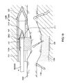
- FIG. 17 is a cross-sectional view showing a blood vessel peeling device used in a blood vessel peeling method according to a fifth embodiment of the present invention.
- FIG. 18 is a diagram illustrating a blood vessel peeling method using the blood vessel peeling device shown in FIG.
- FIG. 19 is a cross-sectional view showing a modified example of the blood vessel peeling device shown in FIG.
- This embodiment is the same as the first embodiment described above except that the configuration of the movable part is mainly different.
- the main body portion 210 of the guide portion 200D is provided with a slit 212 extending in the axial direction.
- the connecting portion 312 of the movable portion 300D has a lumen (through hole) 312a into which the imaging device 400 can be inserted at a position located in the guide portion 200D in a state of being connected to the rail 211, and a lumen 312a.
- An observation unit 312b that covers the opening on the distal end side and has optical transparency is provided.
- the imaging device 400 also serves as the operation unit 500.
- the imaging device 400 is inserted.
- the imaging device 400 can observe the outer wall of the great saphenous vein 1000 via the observation unit 312b and the slit 212.
- the imaging device 400 is pushed forward to move the movable part 300 ⁇ / b> D to perform a peeling operation.
- the peeling operation can be performed while observing the large saphenous vein 1000 and its periphery with the imaging device 400, the operation can be performed with higher accuracy.
- the guide unit 200 may be positioned outside the movable unit 300 as in the second embodiment described above.
- the outer wall of the great saphenous vein 1000 can be observed by the imaging device 400 via the rail 211 for guiding the movable part 300D. Therefore, the slit 212 can be omitted, and the configuration of the guide part 200D becomes simpler. Further, by omitting the slit 212, for example, the living tissue is prevented from entering the guide part 200D through the slit 212, and the movable part 300 can be moved more smoothly.
- FIG. 20 is a side view showing a movable part included in a blood vessel peeling device used in the blood vessel peeling method according to the sixth embodiment of the present invention.
- This embodiment is the same as the first embodiment described above except that the configuration of the movable part is mainly different.
- the tip end face F1 of the annular portion 340 is inclined with respect to the central axis J as shown in FIG.
- the peeling part 350 can be made sharper and the more excellent peeling characteristic can be exhibited in the peeling operation in the second step of the blood vessel peeling method.
- the inclination angle ⁇ of the front end face F1 with respect to the central axis J is not particularly limited, but may be, for example, about 30 ° to 60 °.
- FIG. 21 is a side view and a cross-sectional view showing a movable part included in a blood vessel peeling device used in a blood vessel peeling method according to a seventh embodiment of the present invention.
- FIG. 21C is a cross-sectional view taken along the line BB in FIG. Further, in FIG. 21A, the second vibration damping unit is not shown.
- This embodiment is the same as the first embodiment described above except that the configuration of the movable part is mainly different.
- the movable part 300 ⁇ / b> F further includes a vibration element (vibration part) 380 and a vibration reduction part 370 provided in the annular part 340.
- the vibration element 380 is a vibration source for vibrating the annular portion 340.
- the vibration element 380 has a strip shape (long shape), and a plurality of vibration elements 380 are arranged along the circumferential direction of the annular portion 340. More specifically, one vibration element 380 is disposed between a pair of adjacent grooves 390.
- the configuration of the vibration element 380 is not particularly limited as long as the annular portion 340 can be vibrated at a predetermined frequency.
- ZnO zinc oxide
- AlN aluminum nitride
- PZT lead zirconate titanate
- a piezoelectric layer made of a piezoelectric material is sandwiched between a pair of electrode layers.
- the vibration frequency of the annular portion 340 that is vibrated by the vibration element 380 is not particularly limited.
- the tissue can be removed without dissolving (releasing) blood vessels, skin, and muscles around the saphenous vein 1000.
- a frequency that can be dissolved (released) is preferable, and such a frequency is preferably about 20 to 60 kHz, and more preferably 30 to 40 kHz. Thereby, substantially only the tissue can be dissolved while protecting the saphenous vein 1000.
- the vibration damping unit 370 has a function of absorbing and attenuating the vibration of the annular portion 340 caused by the vibration element 380.
- Such a vibration reduction unit 370 includes a first vibration reduction unit 371 disposed on the inner peripheral surface of the annular part 340 and a second vibration reduction unit 372 disposed on the outer peripheral surface of the annular part 340. is doing.
- first and second vibration damping units 371 and 372 are arranged so as not to overlap the peeling unit 350, respectively. That is, the peeling part 350 protrudes from between the first and second vibration damping parts 371 and 372, and the part is exposed to the outside. Therefore, when the annular portion 340 is vibrated, the vibration is mainly transmitted to the outside from the peeling portion 350 and hardly transmitted to the outside from other places (for example, the inner peripheral surface and the outer peripheral surface of the annular portion 340). (Slightly transmitted)
- the second vibration damping unit 372 is disposed so as to cover the vibration element 380 and protects and insulates the vibration element 380.
- the constituent materials of the first and second vibration damping parts 371 and 372 are not particularly limited as long as the vibration of the annular part 340 can be absorbed and attenuated.
- natural rubber butadiene rubber, styrene-butadiene rubber
- Various rubber materials such as urethane rubber, silicone rubber and fluorine rubber can be used.
- the peeling operation in the second step is performed while vibrating the annular portion 340, so that the movable portion 300F is positioned on the front side in the moving direction by the vibration transmitted from the peeling portion 350. Since the tissue can be peeled while being dissolved, the operation can be performed more smoothly. Furthermore, the tissue located inside the annular portion 340, that is, the tissue 1200 that is located around the great saphenous vein 1000 and peels off together with the great saphenous vein 1000 is suppressed, so that the large size can be more reliably increased. The saphenous vein 1000 can be exfoliated while covered with the surrounding tissue 1200. In addition, since the dissolution of the tissue located outside the annular portion 340 is suppressed, unnecessary dissolution of the tissue is reduced.
- the vibration element 380 is disposed on the outer periphery of the annular portion 340.
- the arrangement of the vibration element 380 is not limited thereto, and is disposed on the inner peripheral surface of the annular portion 340, for example. May be.
- the vibration element 380 may be disposed at a place other than the annular portion 340, for example, at the connection portion 312 as long as vibration can be transmitted to the annular portion 340. In this case, the vibration of the vibration element 380 is transmitted to the annular portion 340 via the connection portion 312.
- FIG. 22 is a cross-sectional view showing a blood vessel peeling device used in the blood vessel peeling method according to the eighth embodiment of the present invention.
- FIG. 22B is a cross-sectional view taken along the line CC in FIG.
- This embodiment is the same as the first embodiment described above except that the movable part is mainly positioned with respect to the guide part using a magnet.
- the main body 210 of the guide part 200G is provided with a permanent magnet 240 for connecting (positioning) the movable part 300G.
- the permanent magnet 240 has a bar shape extending along the axial direction of the main body 210 and is disposed at a position facing the rail 211 of the main body 210.
- the permanent magnet 240 has an S pole on the inner peripheral side of the main body 210 and an N pole on the outer peripheral side. That is, each permanent magnet 240 is magnetized along the radial direction of the main body 210.
- Such a permanent magnet 240 is embedded in the outer periphery of the main body 210, and the protrusion of the permanent magnet 240 from the main body 210 is suppressed.
- connection part 312 of the connector 310 is inserted into the guide part 200 via the rail 211.
- the annular part 340 is provided with a permanent magnet 315 for positioning with respect to the main body part 210.
- the permanent magnet 315 is disposed at a position facing the connection portion 312 (that is, a position separated from the connection portion 312 by about 180 °).
- the permanent magnet 315 has an N pole on the inner peripheral side of the annular portion 340 and an S on the outer peripheral side. That is, the permanent magnet 315 is magnetized along the radial direction of the annular portion 340 and in a direction repelling the permanent magnet 240 disposed in the main body portion 210.
- Such a permanent magnet 315 is embedded in the inner periphery of the annular portion 340, thereby preventing the permanent magnet 315 from protruding from the annular portion 340.
- the permanent magnets 240 and 315 are not particularly limited.
- various permanent magnets such as a neodymium magnet, a samarium cobalt magnet, a ferrite magnet, and an alnico magnet can be used.
- the blood vessel peeling device 100G has been described above.
- the number of permanent magnets 240 and 315 is not particularly limited, and may be two or more.
- an annular radial magnet (a magnet magnetized in the radial direction) may be used as the permanent magnet 240, and a substantially C-shaped radial magnet may be used as the permanent magnet 315.
- the repulsive force of the permanent magnets 240 and 315 is obtained.
- the movable part 300G is naturally positioned (centered) with respect to the guide part 200G.
- the peeling operation can be performed by moving the movable unit 300G forward using the operation unit 500.
- the repulsive force of the permanent magnets 240 and 315 works while the movable portion 300G is advanced, and thus the movable portion 300G.
- the greater saphenous vein 1000 can be more reliably peeled while being covered with the surrounding tissue 1200.
- FIG. 23 is a cross-sectional view showing a blood vessel peeling device used in a blood vessel peeling method according to a ninth embodiment of the present invention.
- FIG. 24 is a plan view and a side view of the blood vessel peeling device shown in FIG.
- the present embodiment is mainly the same as the first embodiment described above except that the structure of the movable part is different.
- the movable part 300H includes a connector 310 having a base 311 and a connection part 312; a pair of movable pieces 330 (330 ′, 330 ′′) housed (incorporated) in the base 311;
- the base 311 has a space for accommodating the movable piece 330, and the movable piece 330 is accommodated in this space.
- one movable piece 330 ′ is one of the base portions 311 in a plan view (hereinafter, also simply referred to as “plan view”) viewed from the axial direction of the guide portion 200.
- the other movable piece 330 ′′ is slidable so as to protrude and retract from the end portion, and can be slidably protruded and retracted from the other end portion of the base 311.
- Each movable piece 330 is also slidable.
- a knob (movable piece operation part) 331 protruding toward the base end side of the base 311 is provided. By operating this knob 331, the movable piece 330 is removed from the base 311.
- each movable piece 330 can be protruded or retracted to the base 311.
- the knob 331 When each movable piece 330 is protruded from the base 311 by operating the knob 331, it is as shown in FIGS.
- the movable piece 33 The tips of ', 330 "are connected to each other below the guide portion 200 (on the side opposite to the base portion 311 of the guide portion 200), and an annular portion 340 is formed by the base portion 311 and the movable pieces 330', 330".
- the guide portion 200 is located in the annular portion 340.
- Each movable piece 330 has a peeling portion 350, a groove portion 390, a processing portion 360, and the like, as in the first embodiment described above. Are provided.
- the connector 310 in a state where the movable pieces 330 ′ and 330 ′′ are retracted into the base 311 is connected to the rail 211. Then, each movable piece 330, 330 ′′ is protruded from the base portion 311 to form an annular portion 340. Thereby, the annular portion 340 can be disposed around the large saphenous vein 1000 without cutting the large saphenous vein 1000.
- the movable portion 300G may be advanced along the guide portion 200 to perform the peeling operation.
- the knob 331 protrudes toward the proximal end side of the base 311, the knob 331 is not easily caught by the tissue or the branch blood vessel 1100 during the peeling operation, and the peeling operation can be performed more smoothly.
- FIG. 25 is a cross-sectional view showing a movable part included in a blood vessel peeling device used in a blood vessel peeling method according to a tenth embodiment of the present invention.
- FIG. 26 is a diagram for explaining a blood vessel peeling method using the blood vessel peeling device shown in FIG.
- This embodiment is mainly the same as the first embodiment described above except that the configuration of the movable part is different.
- a pair of slits 213 and 214 extending in the axial direction are arranged in the body portion 210 of the guide portion 200I so as to be separated from each other in the circumferential direction.
- the movable part 300I is attached to the distal end of the main body part 410 of the imaging device 400, and has a belt-like belt-like body 600 shaped in a substantially arc shape (substantially annular shape). And the strip
- the imaging device 400 also serves as the operation unit 500 that moves the movable unit 300I.
- the belt-like body 600 is formed on the guide portion 200I via the slit 213 from the distal end side. As shown in FIG. 25 (b), the tip end portion is retracted into the guide portion 200I through the slit 214.
- An annular portion 340 is formed by a portion protruding from the guide portion 200I of the belt-like body 600.
- belt-shaped body 600 is provided with the peeling part 350, the groove part 390, and the process part 360 similarly to 1st Embodiment mentioned above, respectively.
- the groove 390 and the peeling portion 350 are based on the base of the belt-like body 600 because the movable portion 300I is moved so as to be retracted from the distal end side to the proximal end side of the guide portion 200I. It is arranged facing the end side.
- the first step is performed as shown in FIG. 26A in a state where the movable part 300I is accommodated in the guide part 200I.
- the imaging device 400 is rotated to project the belt-like body 600 from the guide portion 200I to form the annular portion 340. Accordingly, the annular portion 340 can be disposed around the large saphenous vein 1000 without cutting the large saphenous vein 1000.
- the strip-shaped body 600 (movable part 300I) is moved to the base end side while being guided by the slits 213 and 214, and the peeling operation is performed. .
- the large saphenous vein 1000 is peeled off while being covered with the surrounding tissue 1200.
- the blood vessel separation step can be reduced as compared with the first embodiment described above.
- the movable unit 300I is moved from the distal end side to the proximal end side, but conversely, it may be moved from the proximal end side to the distal end side.
- the groove portion 390 may be provided so as to open to the front end side of the belt-like body 600.
- the method of pulling to the base end side as in this embodiment is more effective in that it is easier to control the force (control / adjustment of the moving amount and moving speed of the movable portion 300I).
- FIG. 27 is a plan view showing a blood vessel peeling device used in the blood vessel peeling method according to the eleventh embodiment of the present invention.
- This embodiment is mainly the same as the first embodiment described above except that the configuration of the movable part is different.
- the movable part 300J has a connector 310 connected to the rail 211 of the guide part 200, and a pair of injection nozzles 700 provided on the connector 310.
- the connector 310 has a base portion 311 extending in the width direction orthogonal to the moving direction, and a connection portion 312 that slidably connects the base portion 311 to the rail 211.
- a peeling portion 350 is provided at the distal end portion of the base portion 311, and an injection nozzle 700 is provided at both end portions of the base portion 311.
- the pair of injection nozzles 700 are provided so as to be positioned on both sides of the guide part 200 in a plan view (a plan view shown in FIG. 27, hereinafter simply referred to as “plan view”) viewed from the axial direction of the guide part 200. Yes. Further, from each spray nozzle 700, the liquid L is sprayed obliquely toward the inner side (the guide part 200 side).
- the liquid L ejected from each ejection nozzle 700 intersects below the guide portion 200 (on the side opposite to the connector 310 of the guide portion 200) in plan view. Further, the guide portion 200 and the great saphenous vein 1000 are located in a region S surrounded by the base 311 and the ejection path of the liquid L.
- each spray nozzle 700 can spray (discharge) a small amount of liquid L at high speed and in a pulse shape.
- the branch blood vessel 1100 fine blood vessel
- nerves can be preserved without being damaged, and heat generation of the tissue can be suppressed. Can preserve the function.
- the connector 310 in the second step of the blood vessel peeling method, is moved to the distal end side while ejecting the liquid L from each jet nozzle 700, so that the peeling work can be performed. it can.
- the connector 310 can be connected to the guide part 200 without cutting the great saphenous vein 1000, and the great saphenous vein 1000 is covered with the surrounding tissue 1200. Can be peeled off.
- the branched blood vessel 1100 may not be cut depending on the jetted liquid L. In this case, after the peeling operation, the branch blood vessel 1100 may be cut and hemostatically treated.
- the groove portion 390 and the processing portion 360 are not provided in the base portion 311 as in the first embodiment, but the groove portion 390 and the processing portion 360 are provided in the base portion 311 in the same manner as in FIG. May be. Thereby, in the passage region of the base 311, the branch blood vessel 1100 can be processed.
- FIG. 28 is a side view showing a blood vessel peeling device used in a blood vessel peeling method according to a twelfth embodiment of the present invention.
- This embodiment is mainly the same as the first embodiment described above except that the configuration of the movable part is different.
- the movable part 300 ⁇ / b> K includes a first movable part 301 and a second movable part 302 located on the proximal side with respect to the first movable part 301.
- the first movable portion 301 has the same configuration as the movable portion 300J of the eleventh embodiment described above
- the second movable portion 302 has the same configuration as the movable portion 300 of the first embodiment described above.
- the branch blood vessel 1100 cannot be cut or stopped by the ejection of the liquid L from the first movable portion 301 even if the tissue can be peeled off. Therefore, the second movable portion 302 is provided behind the first movable portion 301, and the branch blood vessel 1100 is cut and stopped by the processing portion 360 included in the second movable portion 302.
- the first movable portion 301 and the second movable portion 302 are connected to the guide portion 200, and the liquid is discharged from the first movable portion 301. While jetting L, the first and second movable parts 301 and 302 are moved to the tip side to perform the peeling operation.
- tissue separation is performed by the first movable unit 301 located in front, and the second movable unit 302 cuts and stops hemostasis of the branch blood vessel 1100 while passing through the separated site. Movement of the movable part 300K in the living body becomes smoother.
- the great saphenous vein 1000 can be peeled off and the branch blood vessel 1100 can be cut and stopped at the same time, a smoother procedure can be performed.
- the blood vessel peeling method of the present invention has been described based on the illustrated embodiment, but the present invention is not limited to this, and the configuration of each part is replaced with an arbitrary configuration having the same function. can do.
- any other component may be added to the present invention.
- bypass blood vessel is collected when performing the blood vessel bypass operation.
- the use of the collected blood vessel is not limited to the bypass blood vessel.
- the blood vessel peeling method of the present invention includes a first step of arranging a guide portion along an outer wall of a blood vessel, and a movable portion arranged around the blood vessel and slidably connected to the guide portion. And a second step of peeling the blood vessel in a state where at least a part of the blood vessel is covered with the surrounding tissue.
- a first step since the guide portion is arranged along the blood vessel, damage to the blood vessel can be suppressed.
- contact between the movable portion and the blood vessel is suppressed by moving the movable portion while guiding the movable portion with the guide portion. Therefore, since damage to blood vessels can be suppressed, excellent workability can be exhibited.
- the blood vessel peeling method of the present invention has industrial applicability.
Landscapes
- Health & Medical Sciences (AREA)
- Life Sciences & Earth Sciences (AREA)
- Surgery (AREA)
- Heart & Thoracic Surgery (AREA)
- Engineering & Computer Science (AREA)
- Biomedical Technology (AREA)
- Nuclear Medicine, Radiotherapy & Molecular Imaging (AREA)
- Medical Informatics (AREA)
- Molecular Biology (AREA)
- Animal Behavior & Ethology (AREA)
- General Health & Medical Sciences (AREA)
- Public Health (AREA)
- Veterinary Medicine (AREA)
- Surgical Instruments (AREA)
Description
本発明は、血管剥離方法に関するものである。
心臓における血管バイパス術(冠動脈バイパス術:CABG)を行う際のバイパス血管として、内胸動脈、胃大網動脈、橈骨動脈に代表される動脈グラフトや、大伏在静脈に代表される静脈グラフトを用いることが広く知られている。また、現在では、動脈グラフト(特に内胸動脈)の方が静脈グラフトよりも長期的な開存率が高いという報告がなされている。このように、長期的な開存率に劣ると言わる静脈グラフトではあるが、近年、静脈グラフトをその周囲の組織(脂肪、結合組織等)に覆われた状態で採取し、組織に覆われたままの状態でバイパス血管として使用することで、長期的な開存率が向上するとの報告もされてきている。そして、静脈グラフトを周囲の組織に覆われた状態で採取することのできるデバイスとして、例えば特許文献1に記載されたデバイスがある。
特許文献1に記載のデバイスでは、バイパス血管として採取する血管内にガイドワイヤ(support member50)を挿入し、このガイドワイヤに案内させつつ筒状部材(portion40)を押し進めることで、血管をその周囲の組織に覆われた状態で採取することができるようになっている。しかしながら、特許文献1に記載のデバイスでは、ガイドワイヤによって血管の内壁が損傷するおそれがあり、血管採取の作業性が悪いという問題がある。
本発明の目的は、血管採取(血管剥離)の作業性に優れる血管剥離方法を提供することにある。
このような目的は、下記(1)~(7)の本発明により達成される。
(1) 血管の外壁に沿ってガイド部を配置する第1ステップと、
前記血管の周囲に配置されると共に前記ガイド部にスライド可能に接続された可動部を、前記ガイド部で案内しつつ移動させ、前記血管をその周囲の少なくとも一部が周囲の組織に覆われた状態で剥離する第2ステップと、を有することを特徴とする血管剥離方法。
(1) 血管の外壁に沿ってガイド部を配置する第1ステップと、
前記血管の周囲に配置されると共に前記ガイド部にスライド可能に接続された可動部を、前記ガイド部で案内しつつ移動させ、前記血管をその周囲の少なくとも一部が周囲の組織に覆われた状態で剥離する第2ステップと、を有することを特徴とする血管剥離方法。
(2) 前記第1ステップでは、前記ガイド部によって前記血管を直線状に変形させる上記(1)に記載の血管剥離方法。
(3) 前記第1ステップでは、生体内を観察しながら前記ガイド部を前記血管の外壁に沿って配置する上記(1)または(2)に記載の血管剥離方法。
(4) 前記第2ステップでは、前記可動部で前記剥離を行うと共に、前記血管から分岐する分岐血管の切断および止血を行う上記(1)ないし(3)のいずれかに記載の血管剥離方法。
(5) 前記第2ステップは、前記ガイド部に前記可動部を接続するステップと、前記可動部を前記移動させるステップと、を有する上記(1)ないし(4)のいずれかに記載の血管剥離方法。
(6) 前記第2ステップでは、生体内を観察しながら前記可動部を移動させる上記(1)ないし(5)のいずれかに記載の血管剥離方法。
(7) 前記第2ステップでは、前記可動部を振動させながら移動させる上記(1)ないし(6)のいずれかに記載の血管剥離方法。
本発明によれば、第1ステップにおいて、血管に沿ってガイド部を配置するため、血管の損傷を抑えることができる。そして、第2ステップにおいて、可動部をガイド部で案内しながら移動することで、可動部と血管との接触が抑制される。このように、本発明によれば、血管の損傷が抑えられるため、優れた作業性を発揮することができる。
以下、本発明の血管剥離方法を添付図面に示す好適な実施形態に基づいて詳細に説明する。
<第1実施形態>
図1は、本発明の第1実施形態に係る血管剥離方法で用いられる血管剥離デバイスを示す斜視図である。図2は、図1に示す血管剥離デバイスが有するガイド部を示す断面図である。図3は、図1に示す血管剥離デバイスが有する可動部を示す平面図である。図4は、図3に示す可動部を示す側面図である。図5は、図3に示す可動部が有する処理部を示す側面図である。図6は、図3に示す可動部の変形例を示す側面図である。図7は、図1に示す血管剥離デバイスが有する可動部の変形例を示す図である。図8は、図1に示す血管剥離デバイスが有する操作部を示す断面図である。図9ないし図12は、それぞれ、図1に示す血管剥離デバイスを用いた血管剥離方法を説明する図である。なお、図2(b)は、同図(a)中のA-A線断面図である。また、以下では、説明の便宜上、図1中の右側を「先端」、左側を「基端」とも言う。
図1は、本発明の第1実施形態に係る血管剥離方法で用いられる血管剥離デバイスを示す斜視図である。図2は、図1に示す血管剥離デバイスが有するガイド部を示す断面図である。図3は、図1に示す血管剥離デバイスが有する可動部を示す平面図である。図4は、図3に示す可動部を示す側面図である。図5は、図3に示す可動部が有する処理部を示す側面図である。図6は、図3に示す可動部の変形例を示す側面図である。図7は、図1に示す血管剥離デバイスが有する可動部の変形例を示す図である。図8は、図1に示す血管剥離デバイスが有する操作部を示す断面図である。図9ないし図12は、それぞれ、図1に示す血管剥離デバイスを用いた血管剥離方法を説明する図である。なお、図2(b)は、同図(a)中のA-A線断面図である。また、以下では、説明の便宜上、図1中の右側を「先端」、左側を「基端」とも言う。
≪血管剥離デバイス≫
図1に示す血管剥離デバイス100は、血管バイパス術(冠動脈バイパス術:CABG)を行う際のバイパス血管として用いられる血管を採取するのに用いられるデバイスであり、血管を周囲の組織(脂肪、結合組織等)に覆われた状態で採取することができる。なお、血管剥離デバイス100を用いて採取する血管としては、バイパス血管として用いることのできる血管であれば特に限定されず、例えば、内胸動脈、胃大網動脈、橈骨動脈、大伏在静脈等が挙げられる。
図1に示す血管剥離デバイス100は、血管バイパス術(冠動脈バイパス術:CABG)を行う際のバイパス血管として用いられる血管を採取するのに用いられるデバイスであり、血管を周囲の組織(脂肪、結合組織等)に覆われた状態で採取することができる。なお、血管剥離デバイス100を用いて採取する血管としては、バイパス血管として用いることのできる血管であれば特に限定されず、例えば、内胸動脈、胃大網動脈、橈骨動脈、大伏在静脈等が挙げられる。
ただし、採取する血管としてはこれらの中でも大伏在静脈であることが好ましい。血管剥離デバイス100を用いることで、前述したように、血管を周囲の組織に覆われた状態で採取することができる。そのため、血管剥離デバイス100を用いて大伏在静脈を採取し、それをバイパス血管として用いることで、術後の長期的な開存率が高くなると考えられる。したがって、以下では、血管剥離デバイス100を用いて大伏在静脈を採取する例について代表して説明する。
血管剥離デバイス100は、図1ないし図8に示すように、大伏在静脈1000の外壁に沿って配置されるガイド部200と、ガイド部200に挿入されるイメージングデバイス400と、ガイド部200で案内されながら生体内を移動する可動部300と、可動部300を移動操作する操作部500と、を有している。以下、これら各部について、順次詳細に説明する。
[ガイド部]
ガイド部200は、図2に示すように、本体部210と、本体部210の先端部に設けられた剥離部(観察部)220と、を有している。
ガイド部200は、図2に示すように、本体部210と、本体部210の先端部に設けられた剥離部(観察部)220と、を有している。
本体部210は、直線状に延在する管状をなしている。また、本体部210には軸方向に延びるスリット状のレール211が設けられている。このレール211は、可動部300の移動を案内するガイド部として機能する。また、レール211は、本体部210の基端に開放しており、この開放した部分(すなわち、本体部210の基端)から可動部300を接続することができるようになっている。後述する「血管剥離方法」でも説明するように、ガイド部200の基端は、生体から露出しているため、ガイド部200の基端側から可動部300を接続可能とすることで、当該接続をより簡単に行うことができる。なお、本体部210の断面形状は、本実施形態のような円形に限定されず、例えば、大伏在静脈1000との並び方向に潰れた扁平形状であってもよい。また、レール211は、可動部300の移動を案内することができればスリット状でなくてもよく、例えば、凹条の溝であってもよいし、凸条の突起であってもよい。
一方、剥離部220は、ガイド部200の先端に向けて先細りしており、円錐形状をなしている。また、剥離部220は、実質的に無色透明であり、光透過性を有している。このような剥離部220は、ガイド部200を生体内で前進させる際に、組織(脂肪、結合組織等)を剥離する機能と、生体内(大伏在静脈1000およびその周囲)を観察する観察部としての機能と、を有している。なお、剥離部220の形状としては、本実施形態のような円錐形に限定されず、例えば、先端が線状となるように先細りしたダックビル形状であってもよい。また、剥離部220は、光透過性を有していれば無色透明に限定されず、赤、青、緑などに着色されていてもよい。
[イメージングデバイス]
イメージングデバイス400は、図2に示すように、長尺な本体部410を有し、この本体部410の先端部に、照明光を出射する照明部420と、ガイド部200の前方を撮像する撮像部430とが設けられている。撮像部430は、例えば、本体部410の先端部に設けられた対物レンズ系と、対物レンズ系に対向設置された撮像素子(例えば、CMOSイメージセンサ、CCDセンサ等の固体撮像素子)と、を備えている。
イメージングデバイス400は、図2に示すように、長尺な本体部410を有し、この本体部410の先端部に、照明光を出射する照明部420と、ガイド部200の前方を撮像する撮像部430とが設けられている。撮像部430は、例えば、本体部410の先端部に設けられた対物レンズ系と、対物レンズ系に対向設置された撮像素子(例えば、CMOSイメージセンサ、CCDセンサ等の固体撮像素子)と、を備えている。
このようなイメージングデバイス400は、図2に示すように、前述したガイド部200内に挿入可能となっている。このように、イメージングデバイス400をガイド部200内に挿入することで、イメージングデバイス400によって、剥離部220を介してガイド部200の前方を観察可能となる。
[可動部]
可動部300は、生体内を移動することで、大伏在静脈1000をその周囲の組織(脂肪、結合組織等)1200に覆われた状態で剥離すると共に、大伏在静脈1000から分岐している分岐血管1100を切断・止血する。このような可動部300は、ガイド部200に着脱自在であり、図3および図4に示すように、ガイド部200のレール211に接続されるコネクタ310と、コネクタ310に装着される装着部320と、剥離部350と、処理部360と、を有している。
可動部300は、生体内を移動することで、大伏在静脈1000をその周囲の組織(脂肪、結合組織等)1200に覆われた状態で剥離すると共に、大伏在静脈1000から分岐している分岐血管1100を切断・止血する。このような可動部300は、ガイド部200に着脱自在であり、図3および図4に示すように、ガイド部200のレール211に接続されるコネクタ310と、コネクタ310に装着される装着部320と、剥離部350と、処理部360と、を有している。
コネクタ310は、略円弧状に湾曲する基部311と、基部311をレール211にスライド可能に接続する接続部312と、を有している。また、基部311の周方向の両端部には、装着部320を装着する溝311a、311bが設けられている。一方、装着部320は、軸方向に延びるスリット321を有し、略C字状の断面形状を有する筒状(管状)となっている。このような装着部320は、スリット321を挟んだ周方向の両端部がコネクタ310の溝311a、311bに係合することにより、コネクタ310に装着される。そして、基部311と装着部320とで構成される環状の環状部340の内側にガイド部200が位置している。また、環状部340の内径は、大伏在静脈1000の外径よりも大きく、使用時には、図3(a)に示すように、環状部340の内側にかつ中心軸J上に大伏在静脈1000が位置するようになっている。
なお、スリット321の幅としては、特に限定されないが、大伏在静脈1000の外径よりも太いことが好ましい。これにより、大伏在静脈1000と非接触(または損傷を伴わない軽い接触)で、コネクタ310に装着部320を装着することができる。そのため、コネクタ310に装着部320を装着する際の大伏在静脈1000の損傷を抑制することができる。ただし、スリット321の幅は、これに限定されず、大伏在静脈1000の外径よりも細くてもよい。この場合には、例えば、装着部320を拡径変形させてスリット321を広げることで、大伏在静脈1000と非接触でコネクタ310に装着部320を装着することができる。
また、環状部340は、その先端部に開放する溝部390を有し、溝部390は、環状部340の周方向に並んで複数配置されている。各溝部390は、その幅が基端側に向けて漸減するテーパー状の血管案内溝部(第1溝部)391と、血管案内溝部391の基端部に接続され、その幅がほぼ一定であるストレート状の血管処理溝部(第2溝部)392と、を有している。
血管案内溝部391は、可動部300を生体内で押し進める際に接触する分岐血管1100を血管処理溝部392に案内する溝部であり、この案内をスムーズに行うためにテーパー状となっている。特に、本実施形態では、隣り合う血管案内溝部391が接しているため、分岐血管1100をいずれかの血管案内溝部391にスムーズに案内することができる。一方、血管処理溝部392は、血管案内溝部391によって案内されてきた分岐血管1100を切断・止血するための溝部であり、各血管処理溝部392には処理部360が設けられている。
処理部360は、図5に示すように、血管処理溝部392内に電界を発生させることのできる一対の電極361、362を有するバイポーラ構造となっている。具体的には、電極361は、血管処理溝部392の基端部(底部)に設けられており、電極362は、血管処理溝部392の幅方向の両側に設けられている。このような電極361、362間に高周波交番電圧を印加することで、血管処理溝部392に案内された分岐血管1100を加熱して切断すると共に、熱凝固して止血する。なお、電極361の先端部361’は、分岐血管1100を切断することができる程度に鋭利であることが好ましい。これにより、少なくとも電極361、362間に発生する電界によって分岐血管1100を熱凝固(止血)することができれば、電極361によって物理的に分岐血管を切断することができる。よって、処理部360による処理の確実性が向上する。
ここで、血管処理溝部392の幅Wとしては、特に限定されないが、図5に示すように、分岐血管1100の外径よりも細いことが好ましい。これにより、血管処理溝部392内で分岐血管1100を潰すことができるため、処理部360による処理(切断・止血)をより確実に行うことができる。
また、環状部340には、大伏在静脈1000の周囲にある組織を剥離する剥離部350が設けられている。剥離部350は、環状部340の先端部に、血管案内溝部391に沿って設けられている。後述する「血管剥離方法」でも説明するように、剥離部350は、可動部300を生体内で先端側へ押し進める際に大伏在静脈1000の周囲にある組織を剥離する機能を有している。このような剥離部350は、分岐血管1100を切断することなく、組織を剥離することができる程度の鋭さを有することが好ましい。これにより、剥離部350による分岐血管1100の切断が抑制されるため、出血を少なく抑えることができ、安全かつスムーズに手技を行うことができる。
以上、可動部300について説明したが、例えば、血管案内溝部391の形状としては、本実施形態の形状に限定されず、例えば、図6(a)に示すように、幅の漸減率が基端側に向けて漸減するような形状であってもよい。このような形状とすることで、剥離部350が丸み付けされるため、剥離部350によって分岐血管1100がより切断され難くなる。また、図6(b)に示すように、隣り合う溝部390同士が離間していてもよい。また、本実施形態では、基部311に溝部390および処理部360が設けられていないが、例えば、図7に示すように、基部311にも装着部320と同様にして溝部390および処理部360を設けてもよい。これにより、可動部300の全周にわたって溝部390および処理部360が配置される。
[操作部]
操作部500は、図8に示すように、棒状をなし、ガイド部200内に挿入可能となっている。そのため、操作部500をガイド部200内に挿入し、その先端でコネクタ310を押圧することで可動部300を移動させることができる。なお、操作部500は、例えば、嵌合、螺合等の手段によってコネクタ310に固定することができるようになっていることが好ましい。これにより、操作部500で可動部300を押し引きすることができる。
操作部500は、図8に示すように、棒状をなし、ガイド部200内に挿入可能となっている。そのため、操作部500をガイド部200内に挿入し、その先端でコネクタ310を押圧することで可動部300を移動させることができる。なお、操作部500は、例えば、嵌合、螺合等の手段によってコネクタ310に固定することができるようになっていることが好ましい。これにより、操作部500で可動部300を押し引きすることができる。
≪血管剥離方法≫
血管剥離デバイス100を用いた血管剥離方法(血管採取方法)は、ガイド部200を大伏在静脈1000の外壁に沿わせて挿入する第1ステップと、ガイド部200に接続された可動部300を移動することで大伏在静脈1000を周囲の組織1200に覆われた状態で剥離する第2ステップと、大伏在静脈1000を結紮した後に切断する第3ステップと、大伏在静脈1000を周囲の組織1200に覆われた状態で摘出する第4ステップと、を有する。
血管剥離デバイス100を用いた血管剥離方法(血管採取方法)は、ガイド部200を大伏在静脈1000の外壁に沿わせて挿入する第1ステップと、ガイド部200に接続された可動部300を移動することで大伏在静脈1000を周囲の組織1200に覆われた状態で剥離する第2ステップと、大伏在静脈1000を結紮した後に切断する第3ステップと、大伏在静脈1000を周囲の組織1200に覆われた状態で摘出する第4ステップと、を有する。
[第1ステップ]
まず、採取する大伏在静脈1000の位置を確認し、その位置に基づいて切開する。次に、図9(a)に示すように、イメージングデバイス400が挿入されたガイド部200を切開部1300から生体内に挿入し、イメージングデバイス400で生体内(大伏在静脈1000)を観察しながらガイド部200を大伏在静脈1000の外壁に沿わせて前進させる。この際、ガイド部200の先端部に設けられた剥離部220によって、組織を大伏在静脈1000から剥離することができるため、ガイド部200をスムーズに前進させることができる。このように、ガイド部200を大伏在静脈1000の外壁に沿わせて前進させることで、図9(b)に示すように、大伏在静脈1000が直線状に矯正された状態となる。
まず、採取する大伏在静脈1000の位置を確認し、その位置に基づいて切開する。次に、図9(a)に示すように、イメージングデバイス400が挿入されたガイド部200を切開部1300から生体内に挿入し、イメージングデバイス400で生体内(大伏在静脈1000)を観察しながらガイド部200を大伏在静脈1000の外壁に沿わせて前進させる。この際、ガイド部200の先端部に設けられた剥離部220によって、組織を大伏在静脈1000から剥離することができるため、ガイド部200をスムーズに前進させることができる。このように、ガイド部200を大伏在静脈1000の外壁に沿わせて前進させることで、図9(b)に示すように、大伏在静脈1000が直線状に矯正された状態となる。
[第2ステップ]
次に、ガイド部200からイメージングデバイス400を抜去した後、図10(a)に示すように、ガイド部200の基端からレール211にコネクタ310を接続し、さらに、コネクタ310との間に大伏在静脈1000が位置するように、コネクタ310に装着部320を装着する。これにより、環状部340が形成され、環状部340内に、大伏在静脈1000が配置される。特に、本実施形態では、環状部340の中心軸J上に大伏在静脈1000が位置している。このように、コネクタ310と装着部320とを組み立てることで環状部340を形成することで、大伏在静脈1000を切断することなく、大伏在静脈1000の周囲に環状部340を配置することができる。なお、ガイド部200からイメージングデバイス400を抜去することなく、ガイド部200にコネクタ310を接続してもよい。
次に、ガイド部200からイメージングデバイス400を抜去した後、図10(a)に示すように、ガイド部200の基端からレール211にコネクタ310を接続し、さらに、コネクタ310との間に大伏在静脈1000が位置するように、コネクタ310に装着部320を装着する。これにより、環状部340が形成され、環状部340内に、大伏在静脈1000が配置される。特に、本実施形態では、環状部340の中心軸J上に大伏在静脈1000が位置している。このように、コネクタ310と装着部320とを組み立てることで環状部340を形成することで、大伏在静脈1000を切断することなく、大伏在静脈1000の周囲に環状部340を配置することができる。なお、ガイド部200からイメージングデバイス400を抜去することなく、ガイド部200にコネクタ310を接続してもよい。
また、本ステップでは、ガイド部200の基端からコネクタ310をレール211に接続するが、ガイド部200の基端部が生体から露出しているため、当該接続をスムーズに行うことができる。また、可動部300をガイド部200に対して着脱自在とし、第2ステップにおいて可動部300をガイド部200に接続することで、第1ステップを可動部300が接続されていない状態のガイド部200を用いて行うことができる。そのため、可動部300が邪魔にならず、第1ステップをよりスムーズに行うことができる。
次に、図10(b)に示すように、操作部500を用いて可動部300を生体内へ押し込み、レール211に沿って(ガイド部200で案内しつつ)生体内を前進させる。可動部300を前進させると、剥離部350によって大伏在静脈1000の周囲の組織1200が剥離されると共に、溝部390によって分岐血管1100が処理部360に案内され、処理部360で切断・止血される。これにより、大伏在静脈1000がその周囲の組織1200で覆われた状態で剥離される。
特に、ガイド部200によって大伏在静脈1000が直線状に矯正されており、かつ、可動部300の中心軸J上に大伏在静脈1000が位置しているため、可動部300と大伏在静脈1000との接触が防止され、さらに、剥離した組織1200のほぼ中心に大伏在静脈1000を位置させることができる。したがって、より正確にかつ偏りなく、大伏在静脈1000をその周囲の組織1200に覆われた状態で剥離することができる。なお、大伏在静脈1000と共に剥離され、大伏在静脈1000の周囲に位置する組織1200の厚みt1としては、特に限定されないが、0.1mm~10mm程度であることが好ましく、1mm~8mm程度であることがより好ましく、3mm~5mm程度であることがさらに好ましい。
なお、説明の便宜上、以下では、可動部300を移動させて、大伏在静脈1000をその周囲の組織1200に覆われた状態で剥離する作業を「剥離作業」とも言う。
[第3ステップ]
次に、大伏在静脈1000を基端側カット予定部1001および先端側カット予定部1002で切断する。具体的には、まず、図11(a)に示すように、大伏在静脈1000の基端側カット予定部1001を挟んだ前後の2箇所を結紮すると共に、先端側カット予定部1002を挟んだ前後の2箇所を結紮する。なお、先端側カット予定部1002側の結紮は、先端側カット予定部1002付近を切開し、この切開部1400を介して行うことができる。次に、図11(b)に示すように、大伏在静脈1000を基端側カット予定部1001および先端側カット予定部1002で切断する。
次に、大伏在静脈1000を基端側カット予定部1001および先端側カット予定部1002で切断する。具体的には、まず、図11(a)に示すように、大伏在静脈1000の基端側カット予定部1001を挟んだ前後の2箇所を結紮すると共に、先端側カット予定部1002を挟んだ前後の2箇所を結紮する。なお、先端側カット予定部1002側の結紮は、先端側カット予定部1002付近を切開し、この切開部1400を介して行うことができる。次に、図11(b)に示すように、大伏在静脈1000を基端側カット予定部1001および先端側カット予定部1002で切断する。
[第4ステップ]
次に、切開部1300を介して、図12に示すように、大伏在静脈1000をその周囲の組織1200に覆われた状態で生体外へ取り出す。
次に、切開部1300を介して、図12に示すように、大伏在静脈1000をその周囲の組織1200に覆われた状態で生体外へ取り出す。
以上のような第1ステップ~第4ステップによって、大伏在静脈1000をその周囲の組織1200に覆われた状態で採取(摘出)することができる。このような状態で採取された大伏在静脈1000は、組織1200で覆われていない大伏在静脈よりも優れた長期開存率を有するバイパス血管となる可能性がある。これは、次の理由によると考えられている。
すなわち、大伏在静脈1000は、動脈のバイパス血管として用いられるが、動脈は、静脈に比べて血圧(血液により受ける内圧)が高い。そのため、組織1200に覆われていない剥き出しの状態の大伏在静脈をバイパス血管として用いると、血圧に耐えられずに大伏在静脈が膨張して血流が低下するおそれがある。また、リモデリング(構造的改変)や組織損傷の修復過程において血管壁が肥厚するおそれもある。このような血管壁の肥厚は、動脈硬化の進展に影響すると考えられている。このような原因から、組織1200に覆われていない剥き出しの状態の大伏在静脈をバイパス血管として用いると、長期的には血管閉塞に繋がってしまうおそれがある。
これに対して、本実施形態のように、大伏在静脈1000を組織1200で覆うことで、組織1200によって大伏在静脈1000の膨張が抑えられると共に、大伏在静脈1000の折れ曲がり等が抑えられるという効果が期待できる。よって、上記のような血流の低下を抑えることができる可能性がある。また、組織1200で覆われていることで、大伏在静脈1000の損傷、具体的には、内皮細胞、平滑筋、栄養血管(小血管網)等の損傷が低減される。よって、上記のような血管壁の肥厚を抑えることができる可能性がある。以上のことから、組織1200に覆われた大伏在静脈1000をバイパス血管として用いることで、優れた長期開存率を発揮することができる可能性がある。特に、本実施形態では、大伏在静脈1000の血管壁や組織1200に栄養血管が残存しているため、バイパス後も、バイパス血管としての大伏在静脈1000に栄養が供給され、上記効果の向上が図られると考えられる。
以上説明したような方法によれば、スムーズかつ的確に大伏在静脈1000をその周囲の組織1200に覆われた状態で摘出することができる。具体的に説明すると、第1ステップにおいて、ガイド部200を大伏在静脈1000の外壁に沿って配置することで、大伏在静脈1000の損傷を抑えることができる。さらに、第2ステップにおいて、可動部300をガイド部200で案内しながら移動させているため、可動部300と大伏在静脈1000の接触が抑制される。そのため、上述の方法によれば、大伏在静脈1000の損傷を抑えつつ、大伏在静脈1000をその周囲の組織1200に覆われた状態で剥離することができる。
特に、第1ステップにおいて、ガイド部200によって大伏在静脈1000を直線状に矯正(変形)しているため、第2ステップをよりスムーズにかつ的確に行うことができる。また、第2ステップが終わるまで、大伏在静脈1000を切断しないため、大伏在静脈1000になるべく長く血を通わせることができる。よって、虚血状態がより短く、損傷の少ない大伏在静脈1000を採取することできる。
なお、本実施形態では、大伏在静脈1000をその全周が組織1200に覆われた状態で採取(剥離)しているが、全周が組織1200で覆われているものに限定されず、大伏在静脈1000をその周囲の少なくとも一部が組織1200に覆われた状態で採取(剥離)できればよい。
<第2実施形態>
図13は、本発明の第2実施形態に係る血管剥離方法で用いられる血管剥離デバイスを示す斜視図である。図14は、図13に示す血管剥離デバイスを用いた血管剥離方法を説明する図である。
図13は、本発明の第2実施形態に係る血管剥離方法で用いられる血管剥離デバイスを示す斜視図である。図14は、図13に示す血管剥離デバイスを用いた血管剥離方法を説明する図である。
以下、この図を参照して第2実施形態について説明するが、前述した実施形態との相違点を中心に説明し、同様の事項については、その説明を省略する。
本実施形態は、主に、操作部の構成が異なること以外は、前述した第1実施形態と同様である。
≪血管剥離デバイス≫
本実施形態の血管剥離デバイス100Aは、図13に示すように、ガイド部200に可動部300を接続した状態で、可動部300(環状部340)の外側にガイド部200が位置している。このような血管剥離デバイス100Aでも、まず、図14(a)に示すように、大伏在静脈1000にガイド部200を沿わせて配置し、次に、図14(b)に示すように、ガイド部200に沿って可動部300を移動させて剥離作業を行うことで、大伏在静脈1000を周囲の組織1200に覆われた状態で剥離することができる。
本実施形態の血管剥離デバイス100Aは、図13に示すように、ガイド部200に可動部300を接続した状態で、可動部300(環状部340)の外側にガイド部200が位置している。このような血管剥離デバイス100Aでも、まず、図14(a)に示すように、大伏在静脈1000にガイド部200を沿わせて配置し、次に、図14(b)に示すように、ガイド部200に沿って可動部300を移動させて剥離作業を行うことで、大伏在静脈1000を周囲の組織1200に覆われた状態で剥離することができる。
このような第2実施形態によっても、前述した第1実施形態と同様の効果を発揮することができる。
<第3実施形態>
図15は、本発明の第3実施形態に係る血管剥離方法で用いられる血管剥離デバイスを示す断面図である。
図15は、本発明の第3実施形態に係る血管剥離方法で用いられる血管剥離デバイスを示す断面図である。
以下、この図を参照して第3実施形態について説明するが、前述した実施形態との相違点を中心に説明し、同様の事項については、その説明を省略する。
本実施形態は、主に、操作部の構成が異なること以外は、前述した第1実施形態と同様である。
≪血管剥離デバイス≫
操作部500Bは、図15に示すように、2本の紐(線状体)511、512を有している。紐511は、一端部がコネクタ310に接続され、他端部がガイド部200の本体部210の先端部に設けられた挿通孔219を経由してガイド部200の基端開口から外部へ引き出されている。一方、紐512は、一端部がコネクタに接続され、他端部がガイド部200の基端側へ引き出されている。そのため、紐511を基端側へ引っ張ることで可動部300を前方(先端側)へ移動させることができ、反対に、紐512を基端側へ引っ張ることで可動部300を後方(基端側)へ移動させることができる。
操作部500Bは、図15に示すように、2本の紐(線状体)511、512を有している。紐511は、一端部がコネクタ310に接続され、他端部がガイド部200の本体部210の先端部に設けられた挿通孔219を経由してガイド部200の基端開口から外部へ引き出されている。一方、紐512は、一端部がコネクタに接続され、他端部がガイド部200の基端側へ引き出されている。そのため、紐511を基端側へ引っ張ることで可動部300を前方(先端側)へ移動させることができ、反対に、紐512を基端側へ引っ張ることで可動部300を後方(基端側)へ移動させることができる。
このような第3実施形態によっても、前述した第1実施形態と同様の効果を発揮することができる。
<第4実施形態>
図16は、本発明の第4実施形態に係る血管剥離方法で用いられる血管剥離デバイスを示す断面図である。
図16は、本発明の第4実施形態に係る血管剥離方法で用いられる血管剥離デバイスを示す断面図である。
以下、この図を参照して第4実施形態について説明するが、前述した実施形態との相違点を中心に説明し、同様の事項については、その説明を省略する。
本実施形態は、主に、操作部の構成が異なること以外は、前述した第1実施形態と同様である。
≪血管剥離デバイス≫
操作部500Cは、図16に示すように、ガイド部200Cに挿入可能な棒状をなしており、その外周に雄ネジ部520が設けられている。一方、ガイド部200Cの本体部210の内周面には、雄ネジ部520に螺号する雌ネジ部218が設けられている。そのため、雄ネジ部520を雌ネジ部218に螺号させた状態で、操作部500Cを回転させることにより、可動部300がガイド部200Cで案内されつつ移動する。このような構成によれば、例えば、前述した第1実施形態と比較して、可動部300の移動をコントロールし易くなる。
操作部500Cは、図16に示すように、ガイド部200Cに挿入可能な棒状をなしており、その外周に雄ネジ部520が設けられている。一方、ガイド部200Cの本体部210の内周面には、雄ネジ部520に螺号する雌ネジ部218が設けられている。そのため、雄ネジ部520を雌ネジ部218に螺号させた状態で、操作部500Cを回転させることにより、可動部300がガイド部200Cで案内されつつ移動する。このような構成によれば、例えば、前述した第1実施形態と比較して、可動部300の移動をコントロールし易くなる。
このような第4実施形態によっても、前述した第1実施形態と同様の効果を発揮することができる。
<第5実施形態>
図17は、本発明の第5実施形態に係る血管剥離方法で用いられる血管剥離デバイスを示す断面図である。図18は、図17に示す血管剥離デバイスを用いた血管剥離方法を説明する図である。図19は、図17に示す血管剥離デバイスの変形例を示す断面図である。
図17は、本発明の第5実施形態に係る血管剥離方法で用いられる血管剥離デバイスを示す断面図である。図18は、図17に示す血管剥離デバイスを用いた血管剥離方法を説明する図である。図19は、図17に示す血管剥離デバイスの変形例を示す断面図である。
以下、この図を参照して第5実施形態について説明するが、前述した実施形態との相違点を中心に説明し、同様の事項については、その説明を省略する。
本実施形態は、主に、可動部の構成が異なること以外は、前述した第1実施形態と同様である。
≪血管剥離デバイス≫
ガイド部200Dの本体部210には、軸方向に延在するスリット212が設けられている。一方、可動部300Dの接続部312には、レール211に接続された状態でガイド部200D内に位置する箇所に、イメージングデバイス400を挿入可能な内腔(貫通孔)312aと、内腔312aの先端側の開口を覆い、光透過性を有する観察部312bと、が設けられている。また、本実施形態の血管剥離デバイス100Dでは、イメージングデバイス400が操作部500を兼ねている。
ガイド部200Dの本体部210には、軸方向に延在するスリット212が設けられている。一方、可動部300Dの接続部312には、レール211に接続された状態でガイド部200D内に位置する箇所に、イメージングデバイス400を挿入可能な内腔(貫通孔)312aと、内腔312aの先端側の開口を覆い、光透過性を有する観察部312bと、が設けられている。また、本実施形態の血管剥離デバイス100Dでは、イメージングデバイス400が操作部500を兼ねている。
≪血管剥離方法≫
このような構成の血管剥離デバイス100Dによれば、第2ステップにおいて、ガイド部200Dのレール211にコネクタ310を接続し、さらに、コネクタ310に装着部320を装着した後、まず、内腔312aにイメージングデバイス400を挿入する。これにより、観察部312bおよびスリット212を介して、イメージングデバイス400によって大伏在静脈1000の外壁を観察することができる状態となる。次に、図18に示すように、イメージングデバイス400を押し進めて可動部300Dを移動させることで剥離作業を行う。このような本実施形態によれば、イメージングデバイス400で大伏在静脈1000およびその周辺を観察しながら剥離作業を行うことができるので、当該作業をより精度よく行うことができる。
このような構成の血管剥離デバイス100Dによれば、第2ステップにおいて、ガイド部200Dのレール211にコネクタ310を接続し、さらに、コネクタ310に装着部320を装着した後、まず、内腔312aにイメージングデバイス400を挿入する。これにより、観察部312bおよびスリット212を介して、イメージングデバイス400によって大伏在静脈1000の外壁を観察することができる状態となる。次に、図18に示すように、イメージングデバイス400を押し進めて可動部300Dを移動させることで剥離作業を行う。このような本実施形態によれば、イメージングデバイス400で大伏在静脈1000およびその周辺を観察しながら剥離作業を行うことができるので、当該作業をより精度よく行うことができる。
このような第5実施形態によっても、前述した第1実施形態と同様の効果を発揮することができる。
なお、本実施形態の変形例として、図19に示すように、前述した第2実施形態のように、ガイド部200が可動部300の外側に位置している構成であってもよい。この場合は、可動部300Dを案内するためのレール211を介して、イメージングデバイス400によって大伏在静脈1000の外壁を観察することができる。そのため、スリット212を省略することができ、ガイド部200Dの構成がより簡単なものとなる。また、スリット212を省略することで、例えば、スリット212を介して生体組織がガイド部200D内に侵入することが防止され、可動部300をよりスムーズに移動させることができる。
<第6実施形態>
図20は、本発明の第6実施形態に係る血管剥離方法で用いられる血管剥離デバイスが有する可動部を示す側面図である。
図20は、本発明の第6実施形態に係る血管剥離方法で用いられる血管剥離デバイスが有する可動部を示す側面図である。
以下、この図を参照して第6実施形態について説明するが、前述した実施形態との相違点を中心に説明し、同様の事項については、その説明を省略する。
本実施形態は、主に、可動部の構成が異なること以外は、前述した第1実施形態と同様である。
≪血管剥離デバイス≫
可動部300Eでは、図20に示すように、環状部340の先端面F1が、中心軸Jに対して傾斜している。これにより、剥離部350をより鋭くすることができ、血管剥離方法の第2ステップ中の剥離作業において、より優れた剥離特性を発揮することができる。なお、中心軸Jに対する先端面F1の傾斜角度θとしては、特に限定されないが、例えば、30°~60°程度とすることができる。
可動部300Eでは、図20に示すように、環状部340の先端面F1が、中心軸Jに対して傾斜している。これにより、剥離部350をより鋭くすることができ、血管剥離方法の第2ステップ中の剥離作業において、より優れた剥離特性を発揮することができる。なお、中心軸Jに対する先端面F1の傾斜角度θとしては、特に限定されないが、例えば、30°~60°程度とすることができる。
このような第6実施形態によっても、前述した第1実施形態と同様の効果を発揮することができる。
<第7実施形態>
図21は、本発明の第7実施形態に係る血管剥離方法で用いられる血管剥離デバイスが有する可動部を示す側面図および断面図である。なお、図21(c)は、同図(a)中のB-B線断面図である。また、図21(a)では、第2減振部の図示を省略している。
図21は、本発明の第7実施形態に係る血管剥離方法で用いられる血管剥離デバイスが有する可動部を示す側面図および断面図である。なお、図21(c)は、同図(a)中のB-B線断面図である。また、図21(a)では、第2減振部の図示を省略している。
以下、この図を参照して第7実施形態について説明するが、前述した実施形態との相違点を中心に説明し、同様の事項については、その説明を省略する。
本実施形態は、主に、可動部の構成が異なること以外は、前述した第1実施形態と同様である。
≪血管剥離デバイス≫
可動部300Fは、図21に示すように、環状部340に設けられている振動素子(振動部)380および減振部370をさらに有している。
可動部300Fは、図21に示すように、環状部340に設けられている振動素子(振動部)380および減振部370をさらに有している。
振動素子380は、環状部340を振動させるための振動源である。また、振動素子380は、短冊状(長尺状)をなしており、環状部340の周方向に沿って複数配置されている。より具体的には、隣り合う一対の溝部390の間に1つの振動素子380が配置されている。このように、複数の振動素子380を環状部340の周方向に沿って配置することで、環状部340をムラなくより均一に振動させることができる。なお、振動素子380の構成としては、所定の周波数で環状部340を振動させることができれば、特に限定されないが、例えば、酸化亜鉛(ZnO)、窒化アルミニウム(AlN)、PZT(チタン酸ジルコン酸鉛)等の圧電体からなる圧電体層を一対の電極層で挟み込んだ構成のものを用いることができる。
また、振動素子380によって振動させられる環状部340の振動周波数としては、特に限定されないが、例えば、大伏在静脈1000の周囲にある血管、皮膚、筋肉を溶解(遊離)することなく、組織を溶解(遊離)することができる周波数であることが好ましく、このような周波数としては、20~60kHz程度であることが好ましく、30~40kHzであることがより好ましい。これにより、大伏在静脈1000を保護しつつ、実質的に組織だけを溶解することができる。
減振部370は、振動素子380による環状部340の振動を吸収・減衰する機能を有している。このような減振部370は、環状部340の内周面に配置されている第1減振部371と、環状部340の外周面に配置されている第2減振部372と、を有している。
また、第1、第2減振部371、372は、それぞれ、剥離部350と重ならないように配置されている。すなわち、第1、第2減振部371、372の間から剥離部350が突出し、当該部分が外部に露出した状態となっている。したがって、環状部340を振動させると、その振動は、主に、剥離部350から外部へ伝達され、それ以外の場所(例えば環状部340の内周面、外周面)からは外部へほとんど伝達されない(伝達されても僅かである)。また、第2減振部372は、振動素子380を覆うように配置され、振動素子380を保護、絶縁している。
なお、第1、第2減振部371、372の構成材料としては、環状部340の振動を吸収・減衰することができれば、特に限定されず、例えば、天然ゴム、ブタジエンゴム、スチレン-ブタジエンゴム、ウレタンゴム、シリコーンゴム、フッ素ゴムのような各種ゴム材料を用いることができる。
≪血管剥離方法≫
このような構成の血管剥離デバイス100Fによれば、環状部340を振動させながら第2ステップ中の剥離作業を行うことで、剥離部350から伝わる振動によって可動部300Fの移動方向前方側に位置する組織を溶解しながら剥離することができるため、当該作業をよりスムーズに行うことができる。さらには、環状部340の内側に位置する組織、すなわち、大伏在静脈1000の周囲に位置し、大伏在静脈1000と共に剥離する組織1200の溶解が抑制されているため、より確実に、大伏在静脈1000をその周囲の組織1200に覆われた状態で剥離することができる。加えて、環状部340の外側に位置する組織の溶解が抑制されているため、不必要な組織の溶解が低減される。
このような構成の血管剥離デバイス100Fによれば、環状部340を振動させながら第2ステップ中の剥離作業を行うことで、剥離部350から伝わる振動によって可動部300Fの移動方向前方側に位置する組織を溶解しながら剥離することができるため、当該作業をよりスムーズに行うことができる。さらには、環状部340の内側に位置する組織、すなわち、大伏在静脈1000の周囲に位置し、大伏在静脈1000と共に剥離する組織1200の溶解が抑制されているため、より確実に、大伏在静脈1000をその周囲の組織1200に覆われた状態で剥離することができる。加えて、環状部340の外側に位置する組織の溶解が抑制されているため、不必要な組織の溶解が低減される。
このような第7実施形態によっても、前述した第1実施形態と同様の効果を発揮することができる。
なお、本実施形態では、振動素子380が環状部340の外周に配置されているが、振動素子380の配置としては、これに限定されず、例えば、環状部340の内周面に配置されていてもよい。また、振動素子380は、環状部340に振動を伝達することができれば、環状部340以外の場所、例えば、接続部312に配置されていてもよい。この場合、振動素子380の振動は、接続部312を介して環状部340に伝達される。
<第8実施形態>
図22は、本発明の第8実施形態に係る血管剥離方法で用いられる血管剥離デバイスを示す断面図である。なお、図22(b)は、同図(a)中のC-C線断面図である。
図22は、本発明の第8実施形態に係る血管剥離方法で用いられる血管剥離デバイスを示す断面図である。なお、図22(b)は、同図(a)中のC-C線断面図である。
以下、この図を参照して第8実施形態について説明するが、前述した実施形態との相違点を中心に説明し、同様の事項については、その説明を省略する。
本実施形態は、主に、ガイド部に対する可動部の位置決めを、磁石を用いて行っていること以外は、前述した第1実施形態と同様である。
≪血管剥離デバイス≫
ガイド部200Gの本体部210には、図22に示すように、可動部300Gを接続(位置決め)するための永久磁石240が設けられている。永久磁石240は、本体部210の軸方向に沿って延在する棒状をなしており、本体部210のレール211と対向する位置に配置されている。また、永久磁石240は、本体部210の内周側がS極、外周側がN極となっている。すなわち、各永久磁石240は、本体部210の径方向に沿って磁化されている。このような永久磁石240は、本体部210の外周に埋設されており、本体部210からの永久磁石240の突出が抑えられている。
ガイド部200Gの本体部210には、図22に示すように、可動部300Gを接続(位置決め)するための永久磁石240が設けられている。永久磁石240は、本体部210の軸方向に沿って延在する棒状をなしており、本体部210のレール211と対向する位置に配置されている。また、永久磁石240は、本体部210の内周側がS極、外周側がN極となっている。すなわち、各永久磁石240は、本体部210の径方向に沿って磁化されている。このような永久磁石240は、本体部210の外周に埋設されており、本体部210からの永久磁石240の突出が抑えられている。
一方、可動部300Gでは、コネクタ310の接続部312がレール211を介してガイド部200内に挿入された状態となっている。また、環状部340には、本体部210に対する位置決めを行うための永久磁石315が設けられている。永久磁石315は、接続部312と対向する位置(すなわち、接続部312と約180°離間した位置)に配置されている。また、永久磁石315は、環状部340の内周側がN極、外周側がSとなっている。すなわち、永久磁石315は、環状部340の径方向に沿って、かつ、本体部210に配置された永久磁石240と反発する向きに磁化されている。このような永久磁石315は、環状部340の内周に埋設されており、これにより、環状部340からの永久磁石315の突出が抑えられている。
このような構成では、接続部312をレール211を介してガイド部200G内に挿入すると、対向する永久磁石240、315同士の磁気的な反発によって、可動部300Gがガイド部200Gの下側へ向けて付勢される。そして、接続部312がガイド部200Gの内周に当接することにより、ガイド部200Gに対して可動部300Gが位置決めされる。
なお、永久磁石240、315としては、特に限定されず、例えば、ネオジム磁石、サマリウムコバルト磁石、フェライト磁石、アルニコ磁石等の各種永久磁石を用いることができる。
以上、血管剥離デバイス100Gについて説明したが、例えば、永久磁石240、315の数としては、特に限定されず、2つ以上であってもよい。また、永久磁石240として環状のラジアル磁石(径方向に磁化した磁石)を用いてもよいし、永久磁石315として略C字型のラジアル磁石を用いてもよい。
≪血管剥離方法≫
このような構成の血管剥離デバイス100Gによれば、血管剥離方法の第2ステップにおいて、可動部300Gを図22に示すようにガイド部200Gの周囲に配置すれば、永久磁石240、315の反発力によって、自然に、可動部300Gがガイド部200Gに対して位置決め(センタリング)される。そして、操作部500を用いて可動部300Gを前進させることで剥離作業を行うことができる。前述したように、永久磁石240がガイド部200Gの軸方向に延在しているため、可動部300Gを前進させている間も、永久磁石240、315の反発力が働き、よって、可動部300Gがガイド部200Gにセンタリングされ続ける。そのため、より確実に、大伏在静脈1000をその周囲の組織1200に覆われた状態で剥離することができる。
このような構成の血管剥離デバイス100Gによれば、血管剥離方法の第2ステップにおいて、可動部300Gを図22に示すようにガイド部200Gの周囲に配置すれば、永久磁石240、315の反発力によって、自然に、可動部300Gがガイド部200Gに対して位置決め(センタリング)される。そして、操作部500を用いて可動部300Gを前進させることで剥離作業を行うことができる。前述したように、永久磁石240がガイド部200Gの軸方向に延在しているため、可動部300Gを前進させている間も、永久磁石240、315の反発力が働き、よって、可動部300Gがガイド部200Gにセンタリングされ続ける。そのため、より確実に、大伏在静脈1000をその周囲の組織1200に覆われた状態で剥離することができる。
このような第8実施形態によっても、前述した第1実施形態と同様の効果を発揮することができる。
<第9実施形態>
図23は、本発明の第9実施形態に係る血管剥離方法で用いられる血管剥離デバイスを示す断面図である。図24は、図23に示す血管剥離デバイスの平面図および側面図である。
図23は、本発明の第9実施形態に係る血管剥離方法で用いられる血管剥離デバイスを示す断面図である。図24は、図23に示す血管剥離デバイスの平面図および側面図である。
以下、この図を参照して第9実施形態について説明するが、前述した実施形態との相違点を中心に説明し、同様の事項については、その説明を省略する。
本実施形態は、主に、可動部の構造が異なっていること以外は、前述した第1実施形態と同様である。
≪血管剥離デバイス≫
可動部300Hは、図23(a)に示すように、基部311と接続部312を有するコネクタ310と、基部311に収容(内蔵)された一対の可動片330(330’、330”)と、を有している。基部311には可動片330を収容する空間が形成されており、この空間内に可動片330が収容されている。
可動部300Hは、図23(a)に示すように、基部311と接続部312を有するコネクタ310と、基部311に収容(内蔵)された一対の可動片330(330’、330”)と、を有している。基部311には可動片330を収容する空間が形成されており、この空間内に可動片330が収容されている。
また、図23(b)に示すように、ガイド部200の軸方向から見た平面視(以下、単に「平面視」とも言う。)で、一方の可動片330’は、基部311の一方の端部から突出・退避可能にスライド可能となっており、他方の可動片330”は、基部311の他方の端部から突出・退避可能にスライド可能となっている。また、各可動片330は、図24(a)に示すように、基部311の基端側に突出するつまみ(可動片操作部)331を有しており、このつまみ331を操作することにより、可動片330を基部311から突出させたり、基部311に退避させたりすることができる。つまみ331を操作して、各可動片330を基部311から突出させた突出状態とすると、図23(b)~図24(b)に示すように、可動片330’、330”の先端同士が、ガイド部200の下方(ガイド部200の基部311とは反対側)で接続され、基部311および可動片330’、330”で環状部340が形成される。そして、この環状部340内にガイド部200が位置している。このような各可動片330には、前述した第1実施形態と同様に、剥離部350と、溝部390と、処理部360と、がそれぞれ設けられている。
≪血管剥離方法≫
このような構成の血管剥離デバイス100Hによれば、血管剥離方法の第2ステップにおいて、まず、各可動片330’、330”が基部311内に退避している状態のコネクタ310をレール211に接続し、次いで、各可動片330、330”を基部311から突出させて環状部340を形成する。これにより、大伏在静脈1000を切断せずに、大伏在静脈1000の周囲に環状部340を配置することができる。そして、この状態で可動部300Gをガイド部200に沿って前進させて剥離作業を行えばよい。特に、前述したように、つまみ331が基部311の基端側へ突出しているため、剥離作業の際につまみ331が組織や分岐血管1100に引っ掛かり難く、剥離作業をよりスムーズに行うことができる。
このような構成の血管剥離デバイス100Hによれば、血管剥離方法の第2ステップにおいて、まず、各可動片330’、330”が基部311内に退避している状態のコネクタ310をレール211に接続し、次いで、各可動片330、330”を基部311から突出させて環状部340を形成する。これにより、大伏在静脈1000を切断せずに、大伏在静脈1000の周囲に環状部340を配置することができる。そして、この状態で可動部300Gをガイド部200に沿って前進させて剥離作業を行えばよい。特に、前述したように、つまみ331が基部311の基端側へ突出しているため、剥離作業の際につまみ331が組織や分岐血管1100に引っ掛かり難く、剥離作業をよりスムーズに行うことができる。
このような第9実施形態によっても、前述した第1実施形態と同様の効果を発揮することができる。
<第10実施形態>
図25は、本発明の第10実施形態に係る血管剥離方法で用いられる血管剥離デバイスが有する可動部を示す断面図である。図26は、図25に示す血管剥離デバイスを用いた血管剥離方法を説明する図である。
図25は、本発明の第10実施形態に係る血管剥離方法で用いられる血管剥離デバイスが有する可動部を示す断面図である。図26は、図25に示す血管剥離デバイスを用いた血管剥離方法を説明する図である。
以下、この図を参照して第10実施形態について説明するが、前述した実施形態との相違点を中心に説明し、同様の事項については、その説明を省略する。
本実施形態は、主に、可動部の構成が異なっていること以外は、前述した第1実施形態と同様である。
≪血管剥離デバイス≫
図25(a)に示すように、ガイド部200Iの本体部210には軸方向に延在する一対のスリット213、214が周方向に離間し配置されている。一方、可動部300Iは、イメージングデバイス400の本体部410の先端部に取り付けられ、略円弧状(略環状)に形状付けされた帯状の帯状体600を有している。そして、帯状体600は、縮径するように巻回された状態でガイド部200I内に配置されている。なお、イメージングデバイス400は、可動部300Iを移動させる操作部500を兼ねている。
図25(a)に示すように、ガイド部200Iの本体部210には軸方向に延在する一対のスリット213、214が周方向に離間し配置されている。一方、可動部300Iは、イメージングデバイス400の本体部410の先端部に取り付けられ、略円弧状(略環状)に形状付けされた帯状の帯状体600を有している。そして、帯状体600は、縮径するように巻回された状態でガイド部200I内に配置されている。なお、イメージングデバイス400は、可動部300Iを移動させる操作部500を兼ねている。
このような構成の血管剥離デバイス100Iでは、帯状体600がガイド部200I内に収容された状態でイメージングデバイス400を回転させると、帯状体600がその先端側からスリット213を介してガイド部200Iの外へ突出し、最終的に、図25(b)に示すように、先端部がスリット214を介してガイド部200I内に退避する。そして、帯状体600のガイド部200Iから突出している部分によって環状部340が形成される。なお、帯状体600には前述した第1実施形態と同様に、剥離部350と、溝部390と、処理部360と、がそれぞれ設けられている。ただし、本実施形態では、後述するように、可動部300Iをガイド部200Iの先端側から基端側へ後退させるようにして移動させる関係で、溝部390および剥離部350は、帯状体600の基端側に向いて配置されている。
≪血管剥離方法≫
このような構成の血管剥離デバイス100Iによれば、まず、ガイド部200I内に可動部300Iを収容した状態で、図26(a)に示すように、第1ステップを行う。そして、第2ステップでは、まず、図26(b)に示すように、イメージングデバイス400を回転させて帯状体600をガイド部200Iから突出させ、環状部340を形成する。これにより、大伏在静脈1000を切断せずに、環状部340を大伏在静脈1000の周囲に配置することができる。次に、イメージングデバイス400をガイド部200Iから抜去するように基端側へ引っ張ることで帯状体600(可動部300I)をスリット213、214で案内しつつ基端側へ移動させ、剥離作業を行う。これにより、大伏在静脈1000が周囲の組織1200に覆われた状態で剥離される。このような方法によれば、イメージングデバイス400を抜去すると共に剥離工程が行われるため、前述した第1実施形態と比較して、血管剥離の工程を少なくすることができる。
このような構成の血管剥離デバイス100Iによれば、まず、ガイド部200I内に可動部300Iを収容した状態で、図26(a)に示すように、第1ステップを行う。そして、第2ステップでは、まず、図26(b)に示すように、イメージングデバイス400を回転させて帯状体600をガイド部200Iから突出させ、環状部340を形成する。これにより、大伏在静脈1000を切断せずに、環状部340を大伏在静脈1000の周囲に配置することができる。次に、イメージングデバイス400をガイド部200Iから抜去するように基端側へ引っ張ることで帯状体600(可動部300I)をスリット213、214で案内しつつ基端側へ移動させ、剥離作業を行う。これにより、大伏在静脈1000が周囲の組織1200に覆われた状態で剥離される。このような方法によれば、イメージングデバイス400を抜去すると共に剥離工程が行われるため、前述した第1実施形態と比較して、血管剥離の工程を少なくすることができる。
このような第10実施形態によっても、前述した第1実施形態と同様の効果を発揮することができる。
なお、本実施形態の変形例として、本体部210に1つのスリットしか形成されておらず、この1つのスリットを介して帯状体600の突出・退避を行ってもよい。また、本実施形態では、可動部300Iを先端側から基端側へ移動させているが、反対に、基端側から先端側へ移動させてもよい。この場合は、溝部390を帯状体600の先端側に開放するように設ければよい。ただし、本実施形態のように、基端側へ引っ張るような方法の方が、力の制御(可動部300Iの移動量や移動速度の制御・調整)が容易である点で有効である。
<第11実施形態>
図27は、本発明の第11実施形態に係る血管剥離方法で用いられる血管剥離デバイスを示す平面図である。
図27は、本発明の第11実施形態に係る血管剥離方法で用いられる血管剥離デバイスを示す平面図である。
以下、この図を参照して第11実施形態について説明するが、前述した実施形態との相違点を中心に説明し、同様の事項については、その説明を省略する。
本実施形態は、主に、可動部の構成が異なっていること以外は、前述した第1実施形態と同様である。
≪血管剥離デバイス≫
可動部300Jは、図27に示すように、ガイド部200のレール211に接続されるコネクタ310と、コネクタ310に設けられた一対の噴射ノズル700と、を有している。
可動部300Jは、図27に示すように、ガイド部200のレール211に接続されるコネクタ310と、コネクタ310に設けられた一対の噴射ノズル700と、を有している。
コネクタ310は、その移動方向に直交する幅方向に延びる基部311と、基部311をレール211にスライド可能に接続する接続部312と、を有している。また、基部311の先端部に剥離部350が設けられていると共に、基部311の両端部に噴射ノズル700が設けられている。一対の噴射ノズル700は、ガイド部200の軸方向から見た平面視(図27に示す平面視。以下単に「平面視」と言う)で、ガイド部200の両側に位置するように設けられている。また、各噴射ノズル700からは、液体Lが内側(ガイド部200側)を向いて斜めに噴射される。そして、各噴射ノズル700から噴射された液体Lは、平面視で、ガイド部200の下方(ガイド部200のコネクタ310とは反対側)にて交差する。また、基部311と液体Lの噴射経路とで囲まれた領域Sには、ガイド部200および大伏在静脈1000が位置する。
また、各噴射ノズル700は、微量の液体Lを高速かつパルス状に噴射(吐出)することができる。このような液体Lの噴射方法によれば、例えば、分岐血管1100(細血管)や神経を傷付けずに温存することができ、また、組織の発熱を抑えることができるため、剥離箇所およびその周辺の機能温存を図ることができる。
≪血管剥離方法≫
このような構成の血管剥離デバイス100Jによれば、血管剥離方法の第2ステップにおいて、各噴射ノズル700から液体Lを噴射させながらコネクタ310を先端側へ移動させることで、剥離作業を行うことができる。このような構成および方法によれば、大伏在静脈1000を切断することなくコネクタ310をガイド部200に接続することができると共に、大伏在静脈1000をその周囲の組織1200に覆われた状態で剥離することができる。なお、噴射された液体Lによっては、分岐血管1100を切断することができない場合があるため、その場合には、剥離作業を行った後に、分岐血管1100を切断・止血する処理を行えばよい。
このような構成の血管剥離デバイス100Jによれば、血管剥離方法の第2ステップにおいて、各噴射ノズル700から液体Lを噴射させながらコネクタ310を先端側へ移動させることで、剥離作業を行うことができる。このような構成および方法によれば、大伏在静脈1000を切断することなくコネクタ310をガイド部200に接続することができると共に、大伏在静脈1000をその周囲の組織1200に覆われた状態で剥離することができる。なお、噴射された液体Lによっては、分岐血管1100を切断することができない場合があるため、その場合には、剥離作業を行った後に、分岐血管1100を切断・止血する処理を行えばよい。
このような第11実施形態によっても、前述した第1実施形態と同様の効果を発揮することができる。
なお、本実施形態では、基部311に前述した第1実施形態のような溝部390および処理部360が設けられていないが、図7と同様にして、基部311に溝部390および処理部360を設けてもよい。これにより、基部311の通過領域では、分岐血管1100の処理を行うことができる。
<第12実施形態>
図28は、本発明の第12実施形態に係る血管剥離方法で用いられる血管剥離デバイスを示す側面図である。
図28は、本発明の第12実施形態に係る血管剥離方法で用いられる血管剥離デバイスを示す側面図である。
以下、この図を参照して第12実施形態について説明するが、前述した実施形態との相違点を中心に説明し、同様の事項については、その説明を省略する。
本実施形態は、主に、可動部の構成が異なっていること以外は、前述した第1実施形態と同様である。
≪血管剥離デバイス≫
可動部300Kは、図28に示すように、第1可動部301と、第1可動部301よりも基端側に位置する第2可動部302と、を有している。第1可動部301は、前述した第11実施形態の可動部300Jと同様の構成であり、第2可動部302は、前述した第1実施形態の可動部300と同様の構成である。前述した第11実施形態でも述べたように、第1可動部301からの液体Lの噴射によっては、組織を剥離することができても分岐血管1100の切断・止血を行うことができない。そこで、第1可動部301の後方に第2可動部302を設け、第2可動部302が有する処理部360によって分岐血管1100の切断・止血を行うようになっている。
可動部300Kは、図28に示すように、第1可動部301と、第1可動部301よりも基端側に位置する第2可動部302と、を有している。第1可動部301は、前述した第11実施形態の可動部300Jと同様の構成であり、第2可動部302は、前述した第1実施形態の可動部300と同様の構成である。前述した第11実施形態でも述べたように、第1可動部301からの液体Lの噴射によっては、組織を剥離することができても分岐血管1100の切断・止血を行うことができない。そこで、第1可動部301の後方に第2可動部302を設け、第2可動部302が有する処理部360によって分岐血管1100の切断・止血を行うようになっている。
≪血管剥離方法≫
このような構成の血管剥離デバイス100Kによれば、血管剥離方法の第2ステップにおいて、まず、第1可動部301および第2可動部302をガイド部200に接続し、第1可動部301から液体Lを噴射させつつ、第1、第2可動部301、302を先端側へ移動させて剥離作業を行う。このような方法によれば、前方に位置する第1可動部301によって組織の剥離が行われ、この剥離された箇所を通りつつ第2可動部302が分岐血管1100の切断・止血を行うため、生体内での可動部300Kの移動がよりスムーズになる。また、大伏在静脈1000の剥離と分岐血管1100の切断・止血を同時行うことができるため、よりスムーズな手技が可能となる。
このような構成の血管剥離デバイス100Kによれば、血管剥離方法の第2ステップにおいて、まず、第1可動部301および第2可動部302をガイド部200に接続し、第1可動部301から液体Lを噴射させつつ、第1、第2可動部301、302を先端側へ移動させて剥離作業を行う。このような方法によれば、前方に位置する第1可動部301によって組織の剥離が行われ、この剥離された箇所を通りつつ第2可動部302が分岐血管1100の切断・止血を行うため、生体内での可動部300Kの移動がよりスムーズになる。また、大伏在静脈1000の剥離と分岐血管1100の切断・止血を同時行うことができるため、よりスムーズな手技が可能となる。
このような第12実施形態によっても、前述した第1実施形態と同様の効果を発揮することができる。
以上、本発明の血管剥離方法を、図示の実施形態に基づいて説明したが、本発明はこれに限定されるものではなく、各部の構成は、同様の機能を有する任意の構成のものに置換することができる。また、本発明に、他の任意の構成物が付加されていてもよい。また、各実施形態を適宜組み合わせてもよい。
また、前述した実施形態では、血管バイパス術を行う際のバイパス血管を採取する場合について説明したが、採取した血管の用途は、バイパス血管に限定されない。
本発明の血管剥離方法は、血管の外壁に沿ってガイド部を配置する第1ステップと、前記血管の周囲に配置されると共に前記ガイド部にスライド可能に接続された可動部を、前記ガイド部で案内しつつ移動させ、前記血管をその周囲の少なくとも一部が周囲の組織に覆われた状態で剥離する第2ステップと、を有することを特徴とする。このような方法によれば、第1ステップにおいて、血管に沿ってガイド部を配置するため、血管の損傷を抑えることができる。そして、第2ステップにおいて、可動部をガイド部で案内しながら移動することで、可動部と血管との接触が抑制される。そのため、血管の損傷が抑えられるため、優れた作業性を発揮することができる。
したがって、本発明の血管剥離方法は、産業上の利用可能性を有している。
100 血管剥離デバイス
100A 血管剥離デバイス
100D 血管剥離デバイス
100F 血管剥離デバイス
100G 血管剥離デバイス
100H 血管剥離デバイス
100I 血管剥離デバイス
100J 血管剥離デバイス
100K 血管剥離デバイス
200 ガイド部
200C ガイド部
200D ガイド部
200G ガイド部
200I ガイド部
210 本体部
211 レール
212 スリット
213 スリット
214 スリット
218 雌ネジ部
219 挿通孔
220 剥離部
240 永久磁石
300 可動部
300D 可動部
300E 可動部
300F 可動部
300G 可動部
300H 可動部
300I 可動部
300J 可動部
300K 可動部
301 第1可動部
302 第2可動部
310 コネクタ
311 基部
311a、311b 溝
312 接続部
312a 内腔
312b 観察部
315 永久磁石
320 装着部
321 スリット
330 可動片
330’ 可動片
330” 可動片
331 つまみ
340 環状部
350 剥離部
360 処理部
361、362 電極
361’ 先端部
370 減振部
371 第1減振部
372 第2減振部
380 振動素子
390 溝部
391 血管案内溝部
392 血管処理溝部
400 イメージングデバイス
410 本体部
420 照明部
430 撮像部
500 操作部
500B 操作部
500C 操作部
511、512 紐
520 雄ネジ部
600 帯状体
700 噴射ノズル
1000 大伏在静脈
1001 基端側カット予定部
1002 先端側カット予定部
1100 分岐血管
1200 組織
1300 切開部
1400 切開部
F1 先端面
J 中心軸
L 液体
S 領域
t1 厚み
θ 傾斜角度
100A 血管剥離デバイス
100D 血管剥離デバイス
100F 血管剥離デバイス
100G 血管剥離デバイス
100H 血管剥離デバイス
100I 血管剥離デバイス
100J 血管剥離デバイス
100K 血管剥離デバイス
200 ガイド部
200C ガイド部
200D ガイド部
200G ガイド部
200I ガイド部
210 本体部
211 レール
212 スリット
213 スリット
214 スリット
218 雌ネジ部
219 挿通孔
220 剥離部
240 永久磁石
300 可動部
300D 可動部
300E 可動部
300F 可動部
300G 可動部
300H 可動部
300I 可動部
300J 可動部
300K 可動部
301 第1可動部
302 第2可動部
310 コネクタ
311 基部
311a、311b 溝
312 接続部
312a 内腔
312b 観察部
315 永久磁石
320 装着部
321 スリット
330 可動片
330’ 可動片
330” 可動片
331 つまみ
340 環状部
350 剥離部
360 処理部
361、362 電極
361’ 先端部
370 減振部
371 第1減振部
372 第2減振部
380 振動素子
390 溝部
391 血管案内溝部
392 血管処理溝部
400 イメージングデバイス
410 本体部
420 照明部
430 撮像部
500 操作部
500B 操作部
500C 操作部
511、512 紐
520 雄ネジ部
600 帯状体
700 噴射ノズル
1000 大伏在静脈
1001 基端側カット予定部
1002 先端側カット予定部
1100 分岐血管
1200 組織
1300 切開部
1400 切開部
F1 先端面
J 中心軸
L 液体
S 領域
t1 厚み
θ 傾斜角度
Claims (7)
- 血管の外壁に沿ってガイド部を配置する第1ステップと、
前記血管の周囲に配置されると共に前記ガイド部にスライド可能に接続された可動部を、前記ガイド部で案内しつつ移動させ、前記血管をその周囲の少なくとも一部が周囲の組織に覆われた状態で剥離する第2ステップと、を有することを特徴とする血管剥離方法。 - 前記第1ステップでは、前記ガイド部によって前記血管を直線状に変形させる請求項1に記載の血管剥離方法。
- 前記第1ステップでは、生体内を観察しながら前記ガイド部を前記血管の外壁に沿って配置する請求項1または2に記載の血管剥離方法。
- 前記第2ステップでは、前記可動部で前記剥離を行うと共に、前記血管から分岐する分岐血管の切断および止血を行う請求項1ないし3のいずれか1項に記載の血管剥離方法。
- 前記第2ステップは、前記ガイド部に前記可動部を接続するステップと、前記可動部を前記移動させるステップと、を有する請求項1ないし4のいずれか1項に記載の血管剥離方法。
- 前記第2ステップでは、生体内を観察しながら前記可動部を移動させる請求項1ないし5のいずれか1項に記載の血管剥離方法。
- 前記第2ステップでは、前記可動部を振動させながら移動させる請求項1ないし6のいずれか1項に記載の血管剥離方法。
Applications Claiming Priority (2)
| Application Number | Priority Date | Filing Date | Title |
|---|---|---|---|
| JP2014168856 | 2014-08-21 | ||
| JP2014-168856 | 2014-08-21 |
Publications (1)
| Publication Number | Publication Date |
|---|---|
| WO2016027490A2 true WO2016027490A2 (ja) | 2016-02-25 |
Family
ID=55351356
Family Applications (1)
| Application Number | Title | Priority Date | Filing Date |
|---|---|---|---|
| PCT/JP2015/058097 Ceased WO2016027490A2 (ja) | 2014-08-21 | 2015-03-18 | 血管剥離方法 |
Country Status (1)
| Country | Link |
|---|---|
| WO (1) | WO2016027490A2 (ja) |
-
2015
- 2015-03-18 WO PCT/JP2015/058097 patent/WO2016027490A2/ja not_active Ceased
Similar Documents
| Publication | Publication Date | Title |
|---|---|---|
| US20240252196A1 (en) | Unitary Endoscopic Vessel Harvesting Devices | |
| US9814481B2 (en) | Unitary endoscopic vessel harvesting devices | |
| US9872600B2 (en) | Tissue resection bander and related methods of use | |
| US9119900B2 (en) | Unitary endoscopic vessel harvesting devices | |
| US20040167514A1 (en) | High-frequency knife | |
| EP3737300B1 (en) | Vessel harvesting apparatus | |
| US20230404611A1 (en) | Unitary Endoscopic Vessel Harvesting Devices | |
| US10765444B2 (en) | Medical instrument for ablation of tissue | |
| US20150073207A1 (en) | Single-pass endoscopic vessel harvesting | |
| JP6596019B2 (ja) | 血管剥離デバイス | |
| WO2016027491A1 (ja) | 血管剥離方法および血管剥離デバイス | |
| US10058345B2 (en) | Single-pass endoscopic vessel harvesting | |
| JP6388807B2 (ja) | 血管剥離デバイス | |
| JP6383606B2 (ja) | 血管剥離デバイス | |
| JP2025090611A (ja) | 解剖ツールのためのシステムおよび方法 | |
| JP2016042991A (ja) | 血管剥離デバイス | |
| JP2016042992A (ja) | 血管剥離デバイス | |
| WO2016117151A1 (ja) | 血管剥離デバイス | |
| JP6649122B2 (ja) | 剥離デバイス | |
| US20170164971A1 (en) | Endoscopic tissue manipulation tool | |
| JP2017153600A (ja) | 剥離デバイス | |
| WO2016027492A1 (ja) | 血管剥離方法および血管剥離デバイス | |
| JP6649123B2 (ja) | 剥離デバイス | |
| JP2016042987A (ja) | 血管剥離デバイス | |
| JP2017153604A (ja) | 剥離デバイス |
Legal Events
| Date | Code | Title | Description |
|---|---|---|---|
| 121 | Ep: the epo has been informed by wipo that ep was designated in this application |
Ref document number: 15833610 Country of ref document: EP Kind code of ref document: A2 |
|
| NENP | Non-entry into the national phase in: |
Ref country code: DE |
|
| 122 | Ep: pct application non-entry in european phase |
Ref document number: 15833610 Country of ref document: EP Kind code of ref document: A2 |
|
| NENP | Non-entry into the national phase in: |
Ref country code: JP |