WO2016027441A1 - Icカード、icモジュール、及びicカードシステム - Google Patents
Icカード、icモジュール、及びicカードシステム Download PDFInfo
- Publication number
- WO2016027441A1 WO2016027441A1 PCT/JP2015/004033 JP2015004033W WO2016027441A1 WO 2016027441 A1 WO2016027441 A1 WO 2016027441A1 JP 2015004033 W JP2015004033 W JP 2015004033W WO 2016027441 A1 WO2016027441 A1 WO 2016027441A1
- Authority
- WO
- WIPO (PCT)
- Prior art keywords
- card
- pin
- authentication
- password
- unit
- Prior art date
Links
Images


Classifications
-
- H—ELECTRICITY
- H04—ELECTRIC COMMUNICATION TECHNIQUE
- H04L—TRANSMISSION OF DIGITAL INFORMATION, e.g. TELEGRAPHIC COMMUNICATION
- H04L63/00—Network architectures or network communication protocols for network security
- H04L63/08—Network architectures or network communication protocols for network security for authentication of entities
-
- G—PHYSICS
- G06—COMPUTING; CALCULATING OR COUNTING
- G06F—ELECTRIC DIGITAL DATA PROCESSING
- G06F21/00—Security arrangements for protecting computers, components thereof, programs or data against unauthorised activity
- G06F21/30—Authentication, i.e. establishing the identity or authorisation of security principals
- G06F21/31—User authentication
- G06F21/34—User authentication involving the use of external additional devices, e.g. dongles or smart cards
-
- G—PHYSICS
- G06—COMPUTING; CALCULATING OR COUNTING
- G06K—GRAPHICAL DATA READING; PRESENTATION OF DATA; RECORD CARRIERS; HANDLING RECORD CARRIERS
- G06K19/00—Record carriers for use with machines and with at least a part designed to carry digital markings
- G06K19/06—Record carriers for use with machines and with at least a part designed to carry digital markings characterised by the kind of the digital marking, e.g. shape, nature, code
- G06K19/067—Record carriers with conductive marks, printed circuits or semiconductor circuit elements, e.g. credit or identity cards also with resonating or responding marks without active components
- G06K19/07—Record carriers with conductive marks, printed circuits or semiconductor circuit elements, e.g. credit or identity cards also with resonating or responding marks without active components with integrated circuit chips
- G06K19/0723—Record carriers with conductive marks, printed circuits or semiconductor circuit elements, e.g. credit or identity cards also with resonating or responding marks without active components with integrated circuit chips the record carrier comprising an arrangement for non-contact communication, e.g. wireless communication circuits on transponder cards, non-contact smart cards or RFIDs
-
- G—PHYSICS
- G06—COMPUTING; CALCULATING OR COUNTING
- G06K—GRAPHICAL DATA READING; PRESENTATION OF DATA; RECORD CARRIERS; HANDLING RECORD CARRIERS
- G06K19/00—Record carriers for use with machines and with at least a part designed to carry digital markings
- G06K19/06—Record carriers for use with machines and with at least a part designed to carry digital markings characterised by the kind of the digital marking, e.g. shape, nature, code
- G06K19/067—Record carriers with conductive marks, printed circuits or semiconductor circuit elements, e.g. credit or identity cards also with resonating or responding marks without active components
- G06K19/07—Record carriers with conductive marks, printed circuits or semiconductor circuit elements, e.g. credit or identity cards also with resonating or responding marks without active components with integrated circuit chips
- G06K19/073—Special arrangements for circuits, e.g. for protecting identification code in memory
-
- H—ELECTRICITY
- H04—ELECTRIC COMMUNICATION TECHNIQUE
- H04W—WIRELESS COMMUNICATION NETWORKS
- H04W12/00—Security arrangements; Authentication; Protecting privacy or anonymity
- H04W12/06—Authentication
- H04W12/068—Authentication using credential vaults, e.g. password manager applications or one time password [OTP] applications
Definitions
- the present embodiment relates to an IC card, an IC module, and an IC card system.
- an IC card incorporating an IC chip is widely used.
- a conventional IC card receives a secret password shared with a card holder who is a legitimate card holder, and verifies the received password against the password stored in the IC card. Authenticate the holder's legitimacy.
- static data fixed value
- a third party may pretend to be a card holder and the IC card may be used illegally. there were.
- Patent Document 1 Japanese Patent Application Laid-Open No. 2006-268779
- the problem to be solved by the present invention is to provide an IC card, an IC module and an IC card system capable of improving security.
- the IC card of the embodiment has a generation unit and an authentication unit.
- the generation unit generates a second password, which is a password for authenticating the card user, based on a first password stored in advance in the storage unit, a predetermined parameter, and a predetermined algorithm.
- the authentication unit collates the third password acquired from the external device with the second password, and determines the legitimacy of the card user based on the collation result.
- FIG. 2 is a diagram showing an example of the hardware configuration of an IC card according to the first embodiment.
- FIG. 2 is a block diagram showing an example of the functional configuration of an IC card according to the first embodiment.
- FIG. 1 is a block diagram showing an example of an IC card system according to a first embodiment. The figure which shows the example of data of the card information storage part of 1st Embodiment. 6 is a flowchart showing an example of the operation of the IC card of the first embodiment.
- FIG. 6 is a view showing an example of an authentication process of the IC card of the first embodiment.
- FIG. 7 is a view showing an example of parameter change processing of the IC card of the first embodiment.
- FIG. 6 is a view showing an example of center authentication processing of the IC card system of the first embodiment.
- FIG. 7 is a block diagram showing an example of the functional configuration of an IC card according to a second embodiment. 6 is a flowchart showing an example of the operation of the IC card of the second embodiment. The figure which shows an example of the output process of the frequency information of the IC card of 2nd Embodiment.
- FIG. 13 is a block diagram showing an example of the functional configuration of an IC card according to a third embodiment. The flowchart which shows an example of operation
- FIG. 14 is a block diagram showing an example of the functional configuration of an IC card according to a fourth embodiment.
- the flowchart which shows an example of operation
- FIG. 13 is a block diagram showing an example of the functional configuration of an IC card according to a fifth embodiment;
- FIG. 1 is a diagram showing an example of a hardware configuration of an IC card 1 according to a first embodiment.
- the IC card 1 includes an IC module 100, and the IC module 100 includes a contact portion 3 and an IC chip 10.
- the IC card 1 is formed, for example, by mounting an IC module 100 on a plastic card base.
- the IC card 1 can communicate with the external device 2 through the contact portion 3.
- the IC card 1 receives, for example, a command (processing request) transmitted by the external device 2 via the contact unit 3, and executes processing (command processing) corresponding to the received command. Then, the IC card 1 transmits a response (processing response), which is the execution result of the command processing, to the external device 2 through the contact unit 3.
- the IC card 1 dynamically changes, for example, a password for authenticating the card holder who is the owner of the IC card 1 according to a predetermined algorithm shared between the IC card 1 and the card holder. Determine the validity of the card holder.
- a predetermined algorithm shared between the IC card 1 and the card holder.
- an example using addition processing with a predetermined parameter will be described as an example of the predetermined algorithm.
- FIG. 1 shows a configuration example in the case where the IC card 1 is connected to the external device 2 and, for example, offline processing is performed.
- the external device 2 is a higher-level device that communicates with the IC card 1 and is, for example, a terminal device including a reader / writer device. Also, the external device 2 outputs a command to the IC card 1 to execute command processing. For example, the external device 2 receives a password (for example, a PIN (Personal Identification Number)) from a card holder (card user) who is the owner of the IC card 1, and transmits the password to the IC card 1 to execute authentication processing. .
- a password for example, a PIN (Personal Identification Number)
- the IC module 100 is a module that includes the contact portion 3 and the IC chip 10, and is traded in the form of, for example, COT (Chip On Tape) in which a plurality of IC modules 100 are disposed on a tape.
- the contact portion 3 has terminals for various signals necessary for the IC card 1 to operate.
- terminals of various signals have terminals for receiving power supply voltage, clock signals, reset signals and the like from external device 2, and have serial data input / output terminals (SIO terminals) for communicating with external device 2. .
- the IC chip 10 is, for example, a large scale integration (LSI) such as a one-chip microprocessor.
- the IC chip 10 includes a communication I / F unit 4, a CPU (Central Processing Unit) 5, a ROM (Read Only Memory) 6, a RAM (Random Access Memory) 7, and an EEPROM (Electrically Erasable Programmable ROM) 8. Have.
- LSI large scale integration
- the communication I / F (Interface) unit 4 performs communication (transmission / reception of command / response) between the IC card 1 and the external device 2.
- the CPU 5 executes programs stored in the ROM 6 or the EEPROM 8 to perform various processes of the IC card 1.
- the CPU 5 executes, for example, command processing corresponding to the command received by the communication I / F (Interface) unit 4 via the contact unit 3.
- the ROM 6 is, for example, a non-volatile memory such as a mask ROM, and stores a program for executing various processes of the IC card 1 and data such as a command table.
- the RAM 7 is, for example, a volatile memory such as a static RAM (SRAM), and temporarily stores data used when various processes of the IC card 1 are performed.
- SRAM static RAM
- the EEPROM 8 (an example of a storage unit) is, for example, an electrically rewritable non-volatile memory.
- the EEPROM 8 stores PIN information to be described later, parameters for generating a PIN for authentication, an initial value of the PIN, and the like.
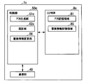
- FIG. 2 is a block diagram showing an example of a functional configuration of the IC card 1 of the present embodiment.
- the IC card 1 includes an EEPROM 8, a communication unit 40, and a control unit 50.
- the EEPROM 8 includes a PIN storage area 81, a parameter storage area 82, and a PIN initial value storage area 83.
- each unit shown in FIG. 2 is realized using the hardware shown in FIG.
- the PIN storage area 81 is a storage area for storing a PIN for authenticating the legitimacy of the card holder.
- the PIN stored in the PIN storage area 81 is used as a PIN (first password) for generating a password for authentication of the card holder (card user) (hereinafter sometimes referred to simply as a PIN for authentication). Ru.
- the PIN stored in the PIN storage area 81 (hereinafter sometimes simply referred to as a stored PIN) is also used as an authentication PIN (second password).
- the parameter storage area 82 is a storage area for storing parameters used when generating the authentication PIN of the card holder.
- the predetermined algorithm for generating (changing) the authentication PIN is addition processing (an example of calculation processing)
- the parameter storage area 82 is, for example, an addition value that is a parameter for addition processing.
- the PIN initial value storage area 83 is a storage area for storing the initial value of the PIN.
- the initial value of the PIN is the PIN registered when registering the card holder in the IC card 1 and the IC card system 20 (see FIG. 3) described later, and the IC card 1 and the IC card system 20 This is the PIN stored first.
- the communication unit 40 is realized by, for example, a program stored in the communication I / F unit 4, the CPU 5, and the ROM 6, and transmits and receives commands and responses with the external device 2 through the contact unit 3.
- the control unit 50 is realized by, for example, the CPU 5, the RAM 7, and the ROM 6 or the EEPROM 8, and controls the IC card 1 in an integrated manner.
- the control unit 50 executes, for example, processing (command processing) of various commands transmitted from the external device 2 to the IC card. Further, the control unit 50 performs, for example, an authentication process using an authentication PIN stored in the PIN storage area 81, and changes the authentication PIN using a predetermined algorithm that can be recognized or stored by the card holder.
- the control unit 50 further includes a PIN generation unit 51, an authentication unit 52, a parameter change unit 53, and an initialization processing unit 54.
- the PIN generation unit 51 stores a stored PIN (first password) stored in advance in the EEPROM 8 (PIN storage area 81), a predetermined parameter, and a predetermined algorithm that can be recognized by the card holder.
- the predetermined algorithm is, for example, arithmetic processing such as addition processing, subtraction processing, multiplication processing, and cyclic processing, and as described above, in the present embodiment, as one example, a storage PIN stored in the EEPROM 8; An example of the addition process with a predetermined parameter will be described.
- the predetermined parameter indicates a parameter to be used when generating the authentication PIN using a predetermined algorithm, and is an added value stored in the EEPROM 8 (parameter storage area 82) as an example here.
- the PIN generation unit 51 generates a new authentication PIN based on, for example, an addition process of the storage PIN stored in the PIN storage area 81 and the addition value stored in the parameter storage area 82. That is, the PIN generation unit 51 generates a value obtained by adding the value of the stored PIN and the addition value as an authentication PIN. Further, when the authentication unit 52 described later determines that the card holder is valid, the PIN generation unit 51 generates an authentication PIN, and stores the authentication PIN in the PIN of the EEPROM 8 as a storage PIN. That is, for example, when the authentication of the card holder by the stored PIN is successful, the PIN generation unit 51 generates the next authentication PIN, and stores the generated authentication PIN as the stored PIN in the PIN storage area 81.
- the authentication unit 52 collates the acquired PIN (third password) acquired from the external device 2 with the authentication PIN, and determines the legitimacy of the card user based on the collation result. That is, the authentication unit 52 collates, for example, the acquired PIN input from the card holder via the external device 2 with the authentication PIN stored in the PIN storage area 81. When the acquired PIN and the authentication PIN match (in the case of matching success), the authentication unit 52 determines that the card holder which has input the acquired PIN to the external device 2 is valid (authentication success). The authentication unit 52 also determines that the card holder that has input the acquired PIN to the external device 2 is not valid (authentication failure) when the acquired PIN and the authentication PIN do not match (in the case of collation failure).
- the parameter change unit 53 requests a change of a predetermined parameter (for example, an addition value) when the authentication unit 52 determines that the card holder is valid (in the case of the authentication success state)
- a predetermined parameter for example, an addition value
- the predetermined parameters stored in the EEPROM 8 are changed. That is, when the authentication by the authentication PIN is successful, when the IC card 1 receives, via the external device 2, a command requesting a change of the added value, which is a predetermined parameter, when the parameter change unit 53 has succeeded in the authentication. , And change the addition value stored in the parameter storage area 82.
- the parameter change unit 53 When the authentication unit 52 succeeds in authentication by the authentication PIN, the parameter change unit 53 newly inputs the addition value stored in the parameter storage area 82 from the card holder, for example, via the external device 2 Change to the addition value. That is, the parameter changing unit 53 stores the addition value acquired from the card holder in the parameter storage area 82 as a new addition value. Further, when the authentication by the authentication PIN is not successful, the parameter change unit 53 does not execute the process of changing the added value.
- the initialization processing unit 54 responds to the initialization request for the authentication PIN, and the EEPROM 8 (PIN storage area 81 The stored PIN stored in the) is changed to the initial value of PIN (PIN for authentication). That is, the initialization processing unit 54 stores the PIN storage area when the IC card 1 receives the command for initializing the authentication PIN via the external device 2 when the authentication by the authentication PIN is successful. Change the stored PIN stored in 81 to the initial value of PIN (PIN for authentication).
- the initialization processing unit 54 stores the initial value of the PIN stored in the PIN initial value storage area 83 in the PIN storage area 81 when the authentication by the authentication PIN is successful. Further, when the authentication by the authentication PIN is not successful, the initialization processing unit 54 does not execute the process of initializing the authentication PIN.
- FIG. 3 is a block diagram showing an example of the IC card system 20 of the present embodiment.
- the IC card system 20 includes an authentication center device 200, an external device 2 and an IC card 1.
- the IC card 1 is connected to the external device 2, and further, connected to the authentication center device 200 via the network NW, for example, showing an example of the configuration in the case of performing online processing.
- the authentication processing of the card holder may be performed by the authentication center apparatus 200.
- the authentication center apparatus 200 performs the authentication of the card holder. Do.
- the authentication center apparatus 200 performs online authentication of the registered cardholder on the IC card 1 via the network NW, and performs various processes (for example, transaction processing) using the IC card 1 It is.
- the authentication center apparatus 200 includes, for example, a center communication unit 210, a center storage unit 220, and a center control unit 230.
- the center communication unit 210 communicates with the external device 2 via the network NW.
- the center storage unit 220 stores information used for various processes performed by the authentication center apparatus 200.
- the center storage unit 220 includes, for example, a card information storage unit 221.
- the card information storage unit 221 stores information on the IC card 1 used in the IC card system 20. For example, as shown in FIG. 4, the card information storage unit 221 associates and stores at least “card ID”, “PIN initial value”, “PIN”, and “PAR”.
- card ID is identification information for identifying the IC card 1 registered in the IC card system 20
- PIN initial value is an initial value of PIN registered by the card holder of the IC card 1 Is shown.
- PIN indicates a PIN for authentication that is generated and changed by a PIN generation unit 231 described later. That is, “PIN” indicates the current PIN value.
- PAR indicates a parameter (for example, an addition value) used when generating an authentication PIN. For example, in the example shown in FIG. 4, the “PIN initial value” in the IC card 1 in which the “card ID” is “XXXXX” indicates “0015” and “PIN” is “0020”. There is. Also, in this case, “PAR” indicates that it is “0005".
- the center control unit 230 is, for example, a processor including a CPU (Central Processing Unit) or the like, and controls the authentication center apparatus 200 in a centralized manner.
- the center control unit 230 performs card holder authentication processing and authentication PIN generation as in the above-described IC card 1.
- the center control unit 230 changes the “PAR” stored in the card information storage unit 221 described above according to the parameter change request acquired from the card holder via the external device 2 and the PIN initialization request, Perform "PIN" initialization processing.
- the center control unit 230 synchronizes the information on the PIN.
- the center control unit 230 includes, for example, a PIN generation unit 231, a center authentication unit 232, a parameter change unit 233, an initialization processing unit 234, and a synchronization processing unit 235.
- the PIN generation unit 231 (an example of the center generation unit) is for authentication based on a stored PIN (a PIN for authentication) stored in the center storage unit 220, a predetermined parameter (for example, an addition value), and a predetermined algorithm. Generate a PIN. That is, in the online processing of the IC card 1, the PIN generation unit 231 executes, for example, the same processing as the above-described PIN generation unit 51.
- the center authentication unit 232 collates the acquired PIN acquired from the card user via the external device 2 with the authentication PIN stored in the card information storage unit 221, and based on the comparison result, the validity of the card holder Determine That is, in the on-line processing of the IC card 1, the center authentication unit 232 executes, for example, the same processing as the above-described authentication unit 52.
- the parameter changing unit 233 responds to a request for changing a predetermined parameter (for example, the addition value).
- a predetermined parameter for example, the addition value.
- the predetermined parameters stored in the information storage unit 221 are changed. That is, in the online process of the IC card 1, the parameter change unit 233 executes, for example, the same process as the parameter change unit 53 described above.
- the parameter change unit 233 acquires a change request of a predetermined parameter requested from the external device 2 by the card holder via the center communication unit 210, and responds to the acquired change request in the card information storage unit 221. Change "PAR" mentioned above.
- the initialization processing unit 234 responds to the authentication PIN initialization request in response to the card information storage unit 221. Change the stored PIN stored by to the initial value of PIN (PIN for authentication). That is, the initialization processing unit 234 performs, for example, the same processing as the above-described initialization processing unit 54 in the online processing of the IC card 1. Note that the initialization processing unit 234 acquires the initialization request for the authentication PIN requested from the external device 2 by the card holder via the center communication unit 210, and stores the card information storage in response to the acquired initialization request. The above-mentioned "PIN" of the part 221 is changed to the value of "PIN initial value" which is the initial value of PIN.
- the synchronization processing unit 235 performs processing to synchronize “PIN” and “PAR” stored in the center storage unit 220 with the IC card 1.
- the synchronization processing unit 235 performs synchronization processing when the stored PIN and predetermined parameters stored in the IC card 1 do not match the “PIN” and “PAR” corresponding to the IC card 1. That is, for example, the synchronization processing unit 235 stores “PIN stored in the center storage unit 220 in association with the stored PIN stored in the IC card 1 and predetermined parameters, and the“ card ID ”corresponding to the IC card 1. And “PAR” do not match, synchronization processing is performed. That is, the synchronization processing unit 235 changes “PIN” and “PAR” stored in the center storage unit 220 into a stored PIN stored in the IC card 1 and a predetermined parameter.
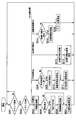
- FIG. 5 is a flowchart showing an example of the operation of the IC card 1 according to the present embodiment.
- the IC card 1 is connected to the external device 2 and subjected to offline processing.
- the IC card 1 first determines whether a command has been received (step S101). That is, it is determined whether the communication unit 40 of the IC card 1 receives a command from the external device 2 via the contact unit 3 and the communication I / F unit 4. If the communication unit 40 receives a command (step S101: YES), the process proceeds to step S102. In addition, when the communication unit 40 does not receive the command (step S101: NO), the communication unit 40 returns to the process of step S101 and repeats the process.
- step S102 the control unit 50 of the IC card 1 branches the process according to the received command.
- the received command is a command to check the PIN (PIN check)
- the process proceeds to step S103.
- the received command is a parameter change request (PAR change)
- the control unit 50 advances the process to step S107.
- the received command is an authentication PIN initialization request (PIN initialization)
- the control unit 50 advances the process to step S110.
- step S103 the authentication unit 52 of the control unit 50 executes a PIN verification process. That is, the authentication unit 52 acquires the acquired PIN input to the external device 2 by the card holder, and collates the acquired PIN with the stored PIN stored in the PIN storage area 81.
- the authentication unit 52 determines whether the collation result is a collation success (step S104). For example, when the verification result is a verification success in which the acquired PIN matches the stored PIN (step S104: YES), the authentication unit 52 stores, for example, information indicating the verification success in the RAM 7. The process then proceeds to step S105. When the verification is successful, the authentication unit 52 determines that the card holder is valid, and enables various transaction processing by the IC card 1. In addition, for example, when the verification result is that the acquired PIN and the stored PIN do not match (mismatch), the authentication unit 52 advances the process to step S106 (step S104: NO). When the verification fails, the authentication unit 52 determines that the card holder is not valid.
- the authentication unit 52 When the card holder is not valid, the authentication unit 52 counts up, for example, error counter information (not shown) of the EEPROM 8 indicating the number of authentication failures, and further, when the error counter information reaches a predetermined count value. The execution of the verification process using the authentication PIN may be prohibited.
- the PIN generation unit 51 stores the generated authentication PIN in the PIN storage area 81 as a storage PIN.
- step S106 the control unit 50 transmits the PIN verification result. That is, the control unit 50 causes the communication unit 40 to transmit the verification result (authentication result) verified by the authentication unit 52 to the external device 2 as a response. After the process of step S106, the control unit 50 returns the process to step S101 and waits for the next command reception.
- step S107 the parameter change unit 53 of the control unit 50 determines whether the user has been authenticated (the card holder has been authenticated).
- the parameter changing unit 53 determines, for example, whether or not the card holder has been authenticated, based on whether or not the information indicating the above-mentioned matching success is stored in the RAM 7. If the card holder has been authenticated (step S107: YES), the parameter changing unit 53 advances the process to step S108. In addition, when the card holder has not been authenticated (step S107: NO), the parameter changing unit 53 advances the process to step S109.
- step S108 the parameter changing unit 53 changes the addition value (PAR) stored in the parameter storage area 82. That is, the parameter changing unit 53 changes, for example, the addition value stored in the parameter storage area 82 to a new addition value acquired from the card holder via the external device 2.
- step S109 the control unit 50 transmits the PAR change result. That is, the control unit 50 causes the communication unit 40 to transmit, as a response, the result (PAR change result) in which the parameter change unit 53 changes the addition value to the external device 2.
- the control unit 50 returns the process to step S101 and waits for the next command reception.
- step S110 the initialization processing unit 54 of the control unit 50 determines whether or not the user is authenticated (the card holder has been authenticated). The initialization processing unit 54 determines whether or not the card holder has been authenticated, for example, based on whether or not the information indicating the matching success described above is stored in the RAM 7. If the card holder has been authenticated (step S110: YES), the initialization processing unit 54 proceeds with the process to step S111. Further, when the card holder has not been authenticated (step S110: NO), the initialization processing unit 54 proceeds with the process to step S112.
- step S111 the initialization processing unit 54 initializes an authentication PIN (stored PIN) stored in the PIN storage area 81. That is, the initialization processing unit 54 changes the stored PIN stored in the PIN storage area 81 to the initial value of the PIN stored in the PIN initial value storage area 83.
- step S112 the control unit 50 transmits the PIN initialization result. That is, the control unit 50 causes the communication unit 40 to transmit the result (PIN initialization result) to the external device 2 as a response, for example, the initialization processing unit 54 initializes the authentication PIN (stored PIN). . After the process of step S112, the control unit 50 returns the process to step S101 and waits for the next command reception.
- FIG. 6 is a diagram showing an example of the authentication process of the IC card 1 according to the present embodiment.
- the IC card 1 is in the state where "PIN” (stored PIN) is "0015" and "PAR” (addition value) is "0005".
- PIN stored PIN
- PAR addition value
- the external device 2 transmits the card holder U1 to the card holder U1. , And outputs a PIN input request (step S201).
- the external device 2 outputs, for example, a display prompting the card holder U1 to input a PIN on a menu screen of a display unit (not shown).
- step S202 when a PIN (for example, "0015") is input to the external device 2 by the card holder U1 (step S202), the external device 2 transmits a PIN verification request to the IC card 1 (step S203). That is, the external device 2 transmits, to the IC card 1, a PIN verification command including “0015” as an acquired PIN, for example.
- a PIN for example, "0015”
- the IC card 1 executes PIN collation processing (for example, collation of “0015”) in accordance with the command of PIN collation (step S204).
- PIN collation processing for example, collation of “0015”
- the authentication unit 52 of the IC card 1 collates “0015”, which is an acquired PIN, with “0015” stored in the PIN storage area 81.
- the authentication unit 52 determines that the verification is successful because “0015” which is the acquired PIN matches “0015” stored in the PIN storage area 81.
- the PIN generation unit 51 of the IC card 1 changes the PIN, and when the verification is failure, the PIN is not changed (step S205).
- the PIN generation unit 51 adds “0005” to “0015” to generate an authentication PIN “0020” to be used next time. Do.
- the PIN generation unit 51 stores the generated authentication PIN “0020” in the PIN storage area 81.
- the IC card 1 transmits the PIN verification result to the external device 2 (step S206). That is, the control unit 50 of the IC card 1 causes the communication unit 40 to transmit the PIN verification result of the authentication unit 52.
- the IC card 1 changes the authentication PIN each time the PIN verification (authentication of the card holder U1) succeeds.
- FIG. 7 is a view showing an example of parameter change processing of the IC card 1 of the present embodiment.
- the IC card 1 is in the state where “PIN” (stored PIN) is “0020” and “PAR” (addition value) is “0005”, and after the authentication process shown in FIG.
- PIN stored PIN
- PAR addition value
- the external device 2 transmits an addition value input request to be changed to the card holder U1 (step S301).
- the external device 2 outputs, for example, on the menu screen of the display unit (not shown), a display prompting the user to input the addition value to be changed to the card holder U1.
- Step S302 when an addition value (for example, "0003”) is input to the external device 2 by the card holder U1 (step S302), the external device 2 transmits a parameter change request to the IC card 1 ( Step S303). That is, the external device 2 transmits to the IC card 1 a command for changing the addition value including the acquired addition value (for example, “0003”).
- an addition value for example, "0003”
- the external device 2 transmits to the IC card 1 a command for changing the addition value including the acquired addition value (for example, “0003”).
- the IC card 1 changes the added value when the card holder U1 is authenticated, and does not change the added value when the card holder U1 is not authenticated (step S304).
- the parameter changing unit 53 changes the addition value “0005” to “0003”. That is, the parameter changing unit 53 changes the addition value “0005” stored in the parameter storage area 82 to the acquired addition value “0003”.
- the IC card 1 transmits the addition value change result to the external device 2 (step S305). That is, the control unit 50 of the IC card 1 causes the communication unit 40 to transmit the addition value result of the parameter change unit 53.
- step S306 the processes of steps S306 to S311 similar to the processes of steps S201 to S206 illustrated in FIG. 6 are performed.
- the addition value stored in the parameter storage area 82 is "0003". Therefore, in step S310, the PIN generation unit 51 adds "0003" to "0020" to generate an authentication PIN "0023" to be used next time.
- the parameter changing unit 53 of the IC card 1 receives the parameter storage area 82 in response to the addition value change command. Change the added value stored by.
- FIG. 8 is a diagram showing an example of center authentication processing of the IC card system 20 of the present embodiment.
- the IC card 1 is in the state where “PIN” (stored PIN) is “0020” and “PAR” (additional value) is “0003”, and the authentication center apparatus 200 is “PIN” (stored A case where the PIN) is “0015” and the “PAR” (addition value) is “0005” will be described. That is, the PIN information does not match between the IC card 1 and the authentication center device 200.
- the external device 2 is connected to the authentication center device 200 via the network NW, and the external device 2 first transmits a PIN synchronization request to the authentication center device 200 (step S401).
- the authentication center apparatus 200 transmits a PIN information request to the IC card 1 via the external device 2 in response to the PIN synchronization request (step S402). That is, in response to a request from authentication center device 200, external device 2 transmits a command for acquiring PIN information to IC card 1.
- the IC card 1 transmits PIN information to the authentication center apparatus 200 via the external device 2 (step S403). That is, control unit 50 of IC card 1 externally stores storage PIN “0020” stored in PIN storage area 81 and addition value “0003” stored in parameter storage area 82 according to a command for acquiring PIN information.
- the communication unit 40 causes the device 2 to transmit, and the external device 2 transmits the PIN information to the authentication center device 200.
- the IC card 1 transmits PIN information, for example, when key verification (center authentication) by a center key shared with the authentication center apparatus 200 is successful. Although illustration is omitted in FIG. 8, here, it is assumed that key verification (center authentication) by the center key is performed before the PIN information request.
- the authentication center apparatus 200 executes synchronization processing of PIN information (step S404).
- the synchronization processing unit 235 of the authentication center device 200 performs synchronization Do the processing. That is, the synchronization processing unit 235 changes “PIN” corresponding to the IC card 1 of the card information storage unit 221 from “0015” to “0020”, and changes “PAR” from “0005” to “0003”.
- the authentication center device 200 transmits the synchronization result to the external device 2 (step S405).
- the external device 2 outputs a PIN input request to the card holder U1 (step S406).
- the external device 2 outputs, for example, a display prompting the card holder U1 to input a PIN on a menu screen of a display unit (not shown).
- Step S407 when a PIN (for example, “0020”) is input to the external device 2 by the card holder U1 (step S407), the external device 2 transmits a PIN verification request to the authentication center device 200 ( Step S408). That is, the external device 2 transmits, for example, a PIN verification request including “0020” to the authentication center device 200 as the acquired PIN.
- a PIN for example, “0020”
- the authentication center apparatus 200 executes PIN collation processing (for example, collation of “0020”) in response to the PIN collation request (step S409).
- PIN collation processing for example, collation of “0020”
- the center authentication unit 232 of the authentication center apparatus 200 collates “0020”, which is an acquired PIN, with “0020” stored in the card information storage unit 221.
- the center authentication unit 232 matches the acquired PIN “0020” with “0020” stored in the card information storage unit 221, it determines that the verification is successful.
- the PIN generation unit 231 of the authentication center device 200 changes the PIN, and when the verification is unsuccessful, the PIN is not changed (step S410).
- the PIN generation unit 231 adds “0003” to “0020” and adds the authentication PIN “0023” to be used next time.
- Generate The PIN generation unit 231 stores the generated authentication PIN “0023” in the card information storage unit 221.
- the authentication center apparatus 200 transmits the PIN verification result to the external apparatus 2 (step S411). That is, the center control unit 230 of the authentication center apparatus 200 causes the center communication unit 210 to transmit the PIN verification result of the center authentication unit 232. As described above, the authentication center apparatus 200 according to the present embodiment changes the authentication PIN each time the PIN verification (authentication of the card holder U1) succeeds in the online process.
- the authentication center apparatus 200 transmits a PIN change request to the IC card 1 (step S412). That is, in order to synchronize the IC card 1 and the PIN information, authentication center device 200 transmits a command of the PIN change request including the changed authentication PIN “0023” to IC card 1 via external device 2. .
- the control unit 50 of the IC card 1 performs change processing of the PIN information in response to the command of the PIN change request (step S413). That is, control unit 50 changes PIN “0020” stored in PIN storage area 81 to “0023”. The control unit 50 performs change processing of PIN information, for example, when key collation (center authentication) by the center key is successful.
- the IC card 1 transmits the PIN change result to the authentication center apparatus 200 via the external device 2 (step S414). That is, the control unit 50 of the IC card 1 causes the communication unit 40 to transmit the PIN change result.
- the authentication center device 200 performs the same authentication processing as the IC card 1, and further, PIN information between the authentication center device 200 and the IC card 1. Synchronize
- the IC card 1 includes the PIN generation unit 51 and the authentication unit 52.
- the PIN generation unit 51 is based on a stored PIN (first password) stored in advance in the EEPROM 8 (storage unit), a predetermined parameter (for example, addition value), and a predetermined algorithm (for example, addition processing).
- a PIN second password
- the authentication unit 52 collates the acquired PIN (third password) acquired from the external device 2 with the authentication PIN, and determines the legitimacy of the card holder based on the collation result.
- the IC card 1 according to the present embodiment changes the authentication PIN as dynamic data for each authentication process, for example, the possibility of a third party spoofing a cardholder and illegal use is reduced. be able to. Therefore, the IC card 1 according to the present embodiment can improve security.
- the EEPROM 8 prestores a predetermined parameter (for example, addition value), and the predetermined algorithm performs predetermined arithmetic processing (for example, storage PIN and predetermined parameter (for example, addition value)) , Addition processing).
- the PIN generation unit 51 generates an authentication PIN based on predetermined arithmetic processing (for example, addition processing) of the stored PIN and a predetermined parameter (for example, addition value).
- predetermined arithmetic processing for example, addition processing
- a predetermined parameter for example, addition value
- the IC card 1 according to the present embodiment includes the parameter change unit 53.
- the parameter change unit 53 responds to a predetermined parameter change request (for example, a change request command), the predetermined parameter (for example, the EEPROM 8 stores). Change the addition value).
- the IC card 1 according to the present embodiment can reduce the possibility that the authentication PIN generation algorithm is revealed to a third party, for example, by changing predetermined parameters periodically. Therefore, the IC card 1 according to the present embodiment can further improve the security.
- the PIN generation unit 51 when the authentication unit 52 determines that the card user is valid, the PIN generation unit 51 generates an authentication PIN to be used next for collation based on a predetermined algorithm.
- the authentication PIN is stored in the EEPROM 8 as a stored PIN.
- the authentication unit 52 collates the acquired PIN with the authentication PIN stored in the EEPROM 8 as the stored PIN when performing the next collation.
- the IC card 1 according to the present embodiment performs the authentication process using the authentication PIN stored in the EEPROM 8. Therefore, the processing amount of the CPU 5 (computational amount compared to the case where the authentication PIN is generated each time) ) Can be reduced. That is, the IC card 1 according to the present embodiment can improve security without applying a load to the CPU 5.
- the EEPROM 8 stores the initial value of the authentication PIN.
- the IC card 1 further stores the storage PIN stored in the EEPROM 8 in response to a request for initialization of the authentication PIN (for example, initialization command) when the authentication unit 52 determines that the card user is valid.
- an initialization processing unit 54 for changing the initial value of the authentication PIN.
- the IC module 100 includes a PIN generation unit 51 and an authentication unit 52.
- the PIN generation unit 51 is based on a stored PIN (first password) stored in advance in the EEPROM 8 (storage unit), a predetermined parameter (for example, addition value), and a predetermined algorithm (for example, addition processing).
- a PIN second password
- the authentication unit 52 collates the acquired PIN (third password) acquired from the external device 2 with the authentication PIN, and determines the legitimacy of the card holder based on the collation result.
- the module 100 according to the present embodiment can improve security as the IC card 1 does.
- the IC card system 20 includes the IC card 1 and the authentication center device 200 connected to the IC card 1 via the external device 2.
- the authentication center apparatus 200 includes a center storage unit 220, a PIN generation unit 231 (center generation unit), a center authentication unit 232, and a synchronization processing unit 235.
- the center storage unit 220 associates and stores card identification information (for example, a card ID) for identifying the IC card 1, a stored PIN (a PIN for next authentication), and a predetermined parameter.
- the PIN generation unit 231 generates an authentication PIN based on the stored PIN stored in the center storage unit 220 and a predetermined parameter (for example, addition value) and a predetermined algorithm (for example, addition processing).
- the center authentication unit 232 collates the acquired PIN acquired from the card holder via the external device 2 with the authentication PIN, and determines the validity of the card holder based on the collation result.
- the synchronization processing unit 235 stores the stored PIN stored in the center storage unit 220 in association with the stored PIN stored in the IC card 1 and a predetermined parameter (for example, an addition value) and the card ID corresponding to the IC card 1.
- a predetermined parameter for example, the addition value
- the stored PIN stored in the center storage unit 220 and the predetermined parameter are changed to the stored PIN stored in the IC card 1 and the predetermined parameter.
- the IC card system 20 according to the present embodiment can improve security as the IC card 1 described above. Further, since the authentication PIN and parameters stored in the IC card 1 and the authentication PIN and parameters stored in the authentication center apparatus 200 can be synchronized, the IC card system 20 according to the present embodiment performs, for example, offline processing Even in the case where there is a mix of online processing and authentication, authentication PINs and parameters can be appropriately changed.
- the PIN generation unit 51 generates an authentication PIN to be collated next time when the authentication process is successful, and stores an authentication PIN to be collated next time in the EEPROM 8 as a stored PIN.
- the PIN generation unit 51 generates an authentication PIN each time based on the stored PIN stored in the EEPROM 8 at the time of authentication processing, and the generated authentication PIN is generated when the authentication processing by the generated authentication PIN is successful.
- the PIN may be stored as a stored PIN.
- an IC card 1a according to a second embodiment will be described with reference to the drawings.
- the IC card 1a outputs information as a hint for generating the current authentication PIN.
- the hardware configuration of the IC card 1a according to the present embodiment is the same as that of the first embodiment shown in FIG. 1, and thus the description thereof is omitted here.
- FIG. 9 is a block diagram showing an example of a functional configuration of the IC card 1a of the present embodiment.
- the IC card 1a includes an EEPROM 8a, a communication unit 40, and a control unit 50a.
- the EEPROM 8 a includes a PIN storage area 81, a parameter storage area 82, a PIN initial value storage area 83, and a count information storage area 84.
- the control unit 50 a includes a PIN generation unit 51 a, an authentication unit 52 a, an initialization processing unit 54 a, and a number information processing unit 55.
- each unit shown in FIG. 9 is realized using the hardware shown in FIG. In this figure, the same components as those in the functional configuration shown in FIG. 2 are assigned the same reference numerals and descriptions thereof will be omitted.
- the number information storage area 84 stores number information indicating the number of times of generation of the authentication PIN.
- the authentication unit 52a executes the following first authentication process and second authentication process.
- the authentication unit 52a collates the acquired PIN with the authentication PIN, and determines the validity of the card holder based on the comparison result.
- the authentication unit 52a collates the acquired initial PIN (fourth password) acquired from the external device 2 with the initial value of the authentication PIN, and based on the comparison result, the card Determine the validity of the holder. That is, in the second authentication process, the authentication unit 52a executes the authentication process using the initial value of the PIN stored in the PIN initial value storage area 83.
- the PIN generation unit 51a generates the authentication PIN when the authentication unit 52a determines that the card holder is valid by the first authentication process, and the number information stored in the EEPROM 8a (the number information storage area 84). Update That is, the PIN generation unit 51 a adds “1” to the value of the number-of-times information stored in the number-of-times information storage area 84 and stores the value in the number-of-times information storage area 84 again.
- the other functions of the PIN generation unit 51a are the same as those of the PIN generation unit 51 of the first embodiment.
- the number information processing unit 55 causes the external device 2 to output the number-of-times information stored in the number-of-times information storage area 84 when the authentication unit 52a determines that the card holder is valid by the second authentication process. If the number-of-times information stored in the number-of-times information storage area 84 is known, the cardholder can calculate the current PIN for authentication from the initial value of the PIN and the value of the parameter.
- the initialization processing unit 54a authenticates the storage PIN stored in the EEPROM 8a in response to the authentication PIN initialization request. Change to the initial PIN value. Then, the initialization processing unit 54a initializes the number information stored in the number information storage area 84 of the EEPROM 8a at the time of this initialization processing. That is, the initialization processing unit 54 a stores, for example, “0” as the number-of-times information that the number-of-times information storage area 84 stores.
- FIG. 10 is a flow chart showing an example of the operation of the IC card 1a of this embodiment.
- the processes of steps S501 and S502 are the same as the processes of steps S101 and S102 shown in FIG. 5, and thus the description thereof is omitted here.
- step S502 if the received command is a command for comparing the PIN (PIN verification), the control unit 50a advances the process to step S503. If the received command is an authentication PIN initialization request (PIN initialization), control unit 50a advances the process to step S508. Further, when the received command is a command for checking the initial value of the PIN (initial PIN check), the control unit 50a advances the process to step S512. In addition, when the received command is a command for requesting the output of the count information (count information request), the control unit 50a advances the process to step S514.
- step S506 The process of PIN verification from step S503 to step S507 (first authentication process) is the same as the process from step S103 to step S106 shown in FIG. 5 except that the process of step S506 is added. .
- step S506 the PIN generation unit 51a of the control unit 50a updates the number information stored in the number information storage area 84. That is, the PIN generation unit 51 a adds “1” to the value of the number-of-times information stored in the number-of-times information storage area 84 and stores the value in the number-of-times information storage area 84 again.
- step S511 The process of PIN initialization from step S508 to step S511 is the same as the process from step S110 to step S112 shown in FIG. 5 except that the process of step S510 is added.
- step S510 the initialization processing unit 54a of the control unit 50a initializes the number information. That is, the initialization processing unit 54 a stores, for example, “0” as the number-of-times information that the number-of-times information storage area 84 stores.
- step S512 the authentication unit 52a of the control unit 50a performs an initial PIN matching process as a second authentication process.
- the authentication unit 52a collates the acquired initial PIN acquired from the external device 2 with the initial value of the authentication PIN, and determines the validity of the card holder based on the comparison result. That is, in the second authentication process, the authentication unit 52a executes the authentication process using the initial value of the PIN stored in the PIN initial value storage area 83.
- the authentication unit 52a stores, in the RAM 7, information indicating the comparison result.
- the authentication unit 52a counts up error counter information (not shown) of the EEPROM 8a indicating the number of authentication failures, for example, in the case of collation failure, and further, when the error counter information reaches a predetermined count value.
- the execution of the verification process by the initial PIN may be prohibited.
- step S513 the control unit 50a transmits the initial PIN comparison result. That is, the control unit 50a causes the communication unit 40 to transmit the response result (authentication result) of the initial PIN collated by the authentication unit 52a to the external device 2 as a response. After the process of step S513, the control unit 50a returns the process to step S501 and waits for the next command reception.
- step S514 the number information processing unit 55 of the control unit 50a determines whether the collation of the initial PIN is successful.
- the number information processing unit 55 determines, for example, whether or not the verification of the initial PIN is successful based on whether or not the information indicating the successful verification of the initial PIN described above is stored in the RAM 7. If the number matching processing of the initial PIN is successful (step S514: YES), the number-of-times information processing unit 55 proceeds with the process to step S515. In addition, if the number information processing unit 55 is not successful in checking the initial PIN (step S514: NO), the process proceeds to step S516.
- step S515 the number information processing unit 55 transmits the number information to the external device 2. That is, the number information processing unit 55 causes the external device 2 to output the number information stored in the number information storage area 84 via the communication unit 40.
- the control unit 50a returns the process to step S501 and waits for the next command reception.
- step S 516 the number information processing unit 55 transmits an error response to the external device 2. That is, the number-of-times information processing unit 55 causes the external device 2 to output a response (error response) indicating that the verification based on the initial PIN is not successful.
- the control unit 50a After the process of step S516, the control unit 50a returns the process to step S501 and waits for the next command reception.
- FIG. 11 is a diagram showing an example of output processing of the number information of the IC card 1a of the present embodiment.
- "initial PIN” initial value of PIN
- "PIN” stored PIN
- "PAR” addition value
- the "number of times” number of times information
- the predetermined algorithm here is addition processing.
- the external device 2 when the card holder U1 instructs the external device 2 to display PIN change count information, the external device 2 outputs an initial PIN input request to the card holder U1 (step S601). ).
- the external device 2 outputs, for example, a display prompting the card holder U1 to input an initial PIN on a menu screen of a display unit (not shown).
- Step S602 when an initial PIN (for example, "0015") is input to the external device 2 by the card holder U1 (step S602), the external device 2 transmits an initial PIN verification request to the IC card 1a. (Step S603). That is, the external device 2 transmits a command of initial PIN verification including, for example, “0015” to the IC card 1 a as the acquired PIN.
- an initial PIN for example, "0015
- the external device 2 transmits a command of initial PIN verification including, for example, “0015” to the IC card 1 a as the acquired PIN.
- the IC card 1a executes an initial PIN collation process (for example, collation of "0015") in response to the command of the initial PIN collation (step S604).
- the authentication unit 52a of the IC card 1a collates “0015”, which is an acquired PIN, with “0015” stored in the PIN initial value storage area 83.
- the authentication unit 52a matches the acquired PIN “0015” with “0015” stored in the PIN initial value storage area 83, it determines that the verification is successful.
- the IC card 1a transmits the initial PIN comparison result to the external device 2 (step S605). That is, the control unit 50a of the IC card 1a causes the communication unit 40 to transmit the initial PIN check result of the authentication unit 52a.
- the external device 2 transmits a count information request to the IC card 1a (step S605). That is, the external device 2 transmits a command of the number information request to the IC card 1a.
- the IC card 1a transmits the number-of-times information to the external device 2 according to the command of the number-of-times information request (step S607). That is, the number information processing unit 55 of the IC card 1 a causes the external device 2 to output the number information “01” stored in the number information storage area 84 via the communication unit 40.
- the external device 2 presents, to the card holder U1, information on the number of times the IC card 1a has output (step S608). That is, the external device 2 displays the number-of-times information "01" acquired from the IC card 1a on the display unit.
- the card holder U1 obtains the number information and easily calculates the present authentication PIN based on the previously recognized algorithm (here, the addition process), the addition value as the parameter, and the number information. be able to.
- the basic process of the IC card 1a of this embodiment is the same as that of the IC card 1 of the first embodiment except that the process related to the above-described number-of-times information is added. I omit the explanation about.
- the IC card 1a does not include the parameter changing unit 53.
- the IC card 1a may include the parameter changing unit 53.
- the initialization processing unit 54a may perform an initialization process.
- the IC card system 20 using the IC card 1a of the present embodiment is the same as the first embodiment except that synchronization processing of the number information is added, so the description thereof is omitted here. .
- the EEPROM 8a stores the initial value of the authentication PIN and the number information indicating the number of times of generation of the authentication PIN.
- the authentication part 52a of this embodiment performs a 1st authentication process and a 2nd authentication process.
- the authentication unit 52a collates the acquired PIN with the authentication PIN, and determines the validity of the card holder based on the comparison result.
- the authentication unit 52a collates the acquired initial PIN (fourth password) acquired from the external device 2 with the initial value of the authentication PIN, and based on the comparison result, the card Determine the validity of the holder.
- the PIN generation unit 51a When it is determined that the card holder is valid by the first authentication process by the authentication unit 52a, the PIN generation unit 51a generates a second password and updates the number-of-times information stored in the EEPROM 8a. Furthermore, the IC card 1 a includes a number information processing unit 55 that causes the external device 2 to output number information when the card holder is determined to be valid by the second authentication process by the authentication unit 52 a.
- the card holder can notify the card holder of the number of times information indicating the number of times of generation of the authentication PIN while securing the security. Therefore, the card holder has forgotten the authentication PIN at present. Even in this case, the card holder can uniquely generate an authentication PIN. Since the IC card 1a according to the present embodiment can enable the authentication process using the authentication PIN even when the card holder has forgotten the authentication PIN at present, convenience can be improved. .
- the IC card 1a includes the initialization processing unit 54a.
- the initialization processing unit 54a responds to the initialization request for the authentication PIN (for example, the initialization command).
- the stored PIN to be stored is changed to the initial value of the authentication PIN.
- the initialization processing unit 54a initializes the number-of-times information stored in the EEPROM 8a in response to the initialization request for the authentication PIN.
- an IC card 1b according to a third embodiment will be described with reference to the drawings.
- the present embodiment is an embodiment showing a modification of the second embodiment described above.
- the authentication process is performed using the authentication PIN stored in the EEPROM 8a as the stored PIN, which is an authentication PIN that is changed each time the authentication process succeeds.
- the authentication process is performed with the authentication PIN generated each time based on the number-of-times information and the initial value of the authentication PIN.
- the hardware configuration of the IC card 1b according to the present embodiment is the same as that of the first embodiment shown in FIG. 1, and thus the description thereof is omitted here.
- FIG. 12 is a block diagram showing an example of the functional configuration of the IC card 1b of this embodiment.
- the IC card 1b includes an EEPROM 8b, a communication unit 40, and a control unit 50b.
- the EEPROM 8 b includes a PIN storage area 81, a parameter storage area 82, and a count information storage area 84.
- the control unit 50 b further includes a PIN generation unit 51 b, an authentication unit 52 b, an initialization processing unit 54 b, and a number information processing unit 55.
- each unit shown in FIG. 12 is realized using the hardware shown in FIG.
- symbol is attached
- the EEPROM 8b does not have the PIN initial value storage area 83, but the PIN storage area 81 stores the initial value of the authentication PIN.
- the authentication unit 52b executes a first authentication process and a second authentication process.
- the PIN generation unit 51b compares the acquired PIN with the authentication PIN generated each time by the PIN generation unit 51b, and determines the validity of the card holder based on the comparison result.
- the PIN generation unit 51b collates the acquired initial PIN (fourth password) acquired from the external device 2 with the initial value of the authentication PIN stored in the PIN storage area 81, Based on the comparison result, the validity of the card holder is determined.
- the PIN generation unit 51b includes an initial value of the authentication PIN stored in the PIN storage area 81, a predetermined parameter (for example, an addition value) stored in the parameter storage area 82, and a predetermined calculation process (for example, addition process). Based on the count information stored in the count information storage area 84, an authentication PIN is generated. Further, when the authentication unit 52b determines that the card holder is valid by the first authentication process, the PIN generation unit 51b updates the number-of-times information stored in the number-of-times information storage area 84. The PIN generation unit 51b performs authentication on the basis of the initial value of the authentication PIN, a predetermined parameter (for example, an addition value), and the number information every time the authentication unit 52b executes the first authentication process. Generate a PIN for
- the initialization processing unit 54b responds to the initialization request for the number information (initialization command for the number information) when the EEPROM 8b (the initialization command for the number information).
- the number information stored in the number information storage area 84) is initialized. That is, the initialization processing unit 54 b stores, for example, “0” as the number-of-times information that the number-of-times information storage area 84 stores.
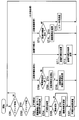
- FIG. 13 is a flowchart showing an example of the operation of the IC card 1b of the present embodiment.
- the processes of steps S701 and S702 are similar to the processes of steps S501 and S502 shown in FIG. 10, and thus the description thereof is omitted here.
- step S702 if the received command is a command for comparing the PIN (PIN verification), the control unit 50b advances the process to step S703. In addition, when the received command is a request for initialization of the number information (number information initialization), the control unit 50b advances the process to step S708. In addition, when the received command is a command for checking the initial value of the PIN (initial PIN check), the control unit 50b advances the process to step S711. In addition, when the received command is a command for requesting the output of the number information (the number information request), the control unit 50b advances the process to step S713.
- step S703 the PIN generation unit 51b of the control unit 50b generates an authentication PIN based on the number-of-times information. For example, when the predetermined algorithm is addition processing and the predetermined parameter is an addition value, the PIN generation unit 51b generates an authentication PIN according to the following equation (1).
- step S704 the authentication unit 52b of the control unit 50b collates the acquired PIN with the authentication PIN generated by the PIN generation unit 51b (step S704).
- step S705 the authentication unit 52b of the control unit 50b determines whether the collation result is a collation success (step S705). If the verification is successful (step S 705: YES), the authentication unit 52 b stores, for example, the information indicating the successful verification in the RAM 7 and advances the process to step S 706. In addition, if the verification unit 52b determines that the verification is not successful (step S705: NO), the process proceeds to step S707.
- the authentication unit 52b determines that the card holder is not valid. When the card holder is not valid, the authentication unit 52b counts up, for example, error counter information (not shown) of the EEPROM 8b indicating the number of authentication failures, and further, when the error counter information reaches a predetermined count value. The execution of the verification process using the authentication PIN may be prohibited.
- step S706 the PIN generation unit 51b updates the number information stored in the number information storage area 84. That is, the PIN generation unit 51 b adds “1” to the value of the number-of-times information stored in the number-of-times information storage area 84 and stores the value in the number-of-times information storage area 84 again.
- the process of the next step S 707 is the same as the process of step S 507 shown in FIG. 10, and thus the description thereof is omitted here.
- step S 708 to step S 710 is the same as the processing from step S 508 to step S 511 shown in FIG. 10 excluding the processing of step S 509, so the description thereof is omitted here.
- the initialization processing unit 54b according to the present embodiment does not need to initialize the authentication PIN, and in step S709, initializes the number information.
- the control unit 50b causes the communication unit 40 to transmit the initialization result of the number information instead of the PIN initialization result.
- step S711 to step S715 is the same as the processing from step S512 to step S516 shown in FIG. 10, and thus the description thereof is omitted here.
- FIG. 14 is a diagram showing an example of authentication processing of the IC card 1b of the embodiment.
- the IC card 1 b has “initial PIN” (initial value of authentication PIN) “0015”, “PAR” (addition value) “0005”, and “number of times” (number information) “01”.
- the predetermined algorithm here is addition processing.
- the external device 2 when the card holder U1 designates transaction processing using the IC card 1b in the external device 2 and connects the IC card 1b to the external device 2, the external device 2 makes a connection to the card holder U1. , And outputs a PIN input request (step S801).
- the external device 2 outputs, for example, a display prompting the card holder U1 to input a PIN on a menu screen of a display unit (not shown).
- step S802 when a PIN (for example, "0020") is input to the external device 2 by the card holder U1 (step S802), the external device 2 transmits a PIN verification request to the IC card 1b (step S803). That is, the external device 2 transmits, for example, a PIN verification command including “0020” to the IC card 1 b as the acquired PIN.
- a PIN for example, "0020”
- the IC card 1b generates an authentication PIN in accordance with the PIN verification command (step S804). That is, the PIN generation unit 51b generates an authentication PIN based on the initial value of the authentication PIN, a predetermined parameter (for example, an addition value), and the number information. Here, the PIN generation unit 51 b generates “0020” as the authentication PIN.
- the IC card 1 b executes a PIN verification process (for example, verification of “0020”) (step S 805).
- a PIN verification process for example, verification of “0020”
- the authentication unit 52 b of the IC card 1 b collates the acquired PIN “0020” with the generated authentication PIN “0020”.
- the authentication unit 52b determines that the verification is successful because the acquired PIN "0020" matches the generated authentication PIN "0020".
- the PIN generation unit 51b of the IC card 1b updates the number information when the verification is successful, and does not update the number information when the verification is unsuccessful (step S806).
- the PIN generation unit 51b since the authentication unit 52b determines that the collation is successful, the PIN generation unit 51b changes the number information from “01” to “02” and stores the number information in the number information storage area 84.
- the IC card 1b transmits the PIN verification result to the external device 2 (step S807). That is, the control unit 50b of the IC card 1b causes the communication unit 40 to transmit the PIN verification result of the authentication unit 52b.
- the EEPROM 8b stores the initial value of the authentication PIN as a storage PIN, and stores the number information indicating the number of times of generation of the authentication PIN.
- the authentication unit 52b executes a first authentication process and a second authentication process.
- the authentication unit 52 b collates the acquired PIN with the authentication PIN, and determines the validity of the card holder based on the comparison result.
- the authentication unit 52b collates the acquired initial PIN acquired from the external device 2 with the initial value of the authentication PIN, and determines the validity of the card holder based on the collation result. Do.
- the PIN generation unit 51b is used for authentication based on the initial value of the authentication PIN, a predetermined parameter (for example, addition value), a predetermined arithmetic processing (for example, addition processing), and the number information stored in the EEPROM 8b. Generate a PIN. Further, when the authentication unit 52b determines that the card holder is valid by the first authentication process, the PIN generation unit 51b updates the number-of-times information stored in the EEPROM 8b. Thus, the IC card 1b according to the present embodiment changes the authentication PIN as dynamic data for each authentication process, so that security can be improved as in the first and second embodiments.
- the IC card 1 b causes the number information processing unit 55 to output the number information to the external device 2 when the second authentication processing by the authentication unit 52 b determines that the card holder is valid. Have.
- the IC card 1b according to the present embodiment uniquely generates an authentication PIN. be able to.
- the IC card 1b stores the EEPROM 8b in response to the initialization request for the number information when the card user is determined to be valid by the first authentication process by the authentication unit 52b.
- An initialization processing unit 54b is provided to initialize the number information.
- an IC card 1c according to a fourth embodiment will be described with reference to the drawings.
- an example in the case of using supply information supplied from the external device 2 as a predetermined parameter for changing the authentication PIN will be described.
- an example of using a replacement process will be described as an example of a predetermined algorithm.
- the hardware configuration of the IC card 1c according to the present embodiment is the same as that of the first embodiment shown in FIG. 1, and thus the description thereof is omitted here.
- FIG. 15 is a block diagram showing an example of the functional configuration of the IC card 1c of this embodiment.
- the IC card 1c includes an EEPROM 8c, a communication unit 40, and a control unit 50c.
- the EEPROM 8 c includes a PIN storage area 81 and a replacement information storage area 85.
- the control unit 50c includes a PIN generation unit 51c, an authentication unit 52c, and a replacement information change unit 56.
- each unit shown in FIG. 15 is realized using the hardware shown in FIG.
- the PIN storage area 81 stores the initial value of the authentication PIN, as in the third embodiment described above.
- the replacement information storage area 85 stores replacement process information.
- the replacement process information indicates at least one of a predetermined position of the authentication PIN, a type of supply information, and a method of generating a predetermined replacement value generated based on the supply information.
- the supply information is information supplied from the external device 2 when the IC card 1c is traded, and the type of supply information is, for example, a transaction date, a transaction time zone, a transaction day, a transaction amount, etc. Is included.
- the PIN generation unit 51c uses the supply information supplied from the external device 2 as a predetermined parameter, and based on the supply information, a predetermined algorithm (for example, replacement process), and an initial value of the authentication PIN, for authentication. Generate a PIN. For example, the PIN generation unit 51c generates an authentication PIN by replacing the lower one digit of the initial value of the authentication PIN with the lower one digit of the transaction date as supply information.
- a predetermined algorithm for example, replacement process
- the replacement information changing unit 56 responds to a request for changing the replacement process information when the EEPROM 8c (replacement information storage area 85) Change stored replacement process information.
- FIG. 16 is a flowchart showing an example of the operation of the IC card 1c of this embodiment.
- the processes of steps S901 and S902 are the same as the processes of steps S101 and S102 shown in FIG. 5, and thus the description thereof is omitted here.
- step S902 if the received command is a command to check the PIN (PIN check), the control unit 50c advances the process to step S903. Further, when the received command is a change request for replacement process information (replacement information change), the control unit 50c advances the process to step S906.
- step S902 the PIN generation unit 51c of the control unit 50c generates an authentication PIN based on the replacement process information. For example, the PIN generation unit 51c generates an authentication PIN by replacing the lower one digit of the initial value of the authentication PIN with the lower one digit of the transaction date as supply information.
- step S904 the authentication unit 52c of the control unit 50c collates the acquired PIN with the authentication PIN generated by the PIN generation unit 51c (step S904).
- step S905 the control unit 50c causes the communication unit 40 to transmit the verification result (authentication result) verified by the authentication unit 52c to the external device 2 as a response.
- step S904 the control unit 50c returns the process to step S901 and waits for the next command reception.
- step S906 the replacement information changing unit 56 of the control unit 50c determines whether the user has been authenticated (the card holder has been authenticated). The replacement information changing unit 56 determines, for example, whether or not the card holder has been authenticated, based on whether or not the information indicating the matching success is stored in the RAM 7. If the card holder has been authenticated (step S906: YES), the replacement information changing unit 56 advances the process to step S907. Further, when the card holder has not been authenticated (step S906: NO), the replacement information changing unit 56 advances the process to step S908.
- step S 907 the replacement information changing unit 56 changes the replacement processing information stored in the replacement information storage area 85. That is, the parameter changing unit 53 changes the replacement process information stored in the replacement information storage area 85 to, for example, new replacement process information acquired from the card holder via the external device 2. For example, when the replacement information changing unit 56 acquires a request for changing the supply information from the transaction date to the transaction amount from the card holder, the replacement information changing unit 56 generates supply information for generating the authentication PIN from the transaction date Information to be changed to the transaction amount is stored in the replacement information storage area 85 as replacement process information.
- step S908 the control unit 50c transmits the substitution information change result. That is, the control unit 50c causes the communication unit 40 to transmit the result (replacement information change result) of the replacement information change unit 56 changing the replacement process information to the external device 2 as a response.
- the control unit 50 c returns the process to step S 901 and waits for the next command reception.
- FIG. 17 is a diagram illustrating an example of an authentication process of the IC card 1c according to the embodiment.
- PIN initial value of PIN for authentication
- transaction date is “Y 1 Y 2 Y 3 Y 4 M 1 M 2 D 1 D 2
- the supply information that is “is already supplied.
- the predetermined algorithm here is a substitution process.
- the external device 2 when the card holder U1 designates the transaction processing using the IC card 1c in the external device 2 and connects the IC card 1c to the external device 2, the external device 2 makes a connection to the card holder U1. , And outputs a PIN input request (step S1001).
- the external device 2 outputs, for example, a display prompting the card holder U1 to input a PIN on a menu screen of a display unit (not shown).
- the least significant digit “D 2 ” of this “trade date” is Replace with the least significant digit of initial value of PIN to generate authentication PIN. That is, when a PIN (for example, "001D 2 ") is input to the external device 2 by the card holder U1 (step S1002), the external device 2 transmits a PIN verification request to the IC card 1c (step S1002) S1003). That is, the external device 2 transmits, for example, a command of PIN verification including “0021D 2 ” to the IC card 1 c as the acquired PIN.
- a PIN for example, "001D 2 ”
- the IC card 1 c generates an authentication PIN in response to the PIN verification command (step S 1004). That is, the PIN generation unit 51c generates the authentication PIN based on the initial value of the authentication PIN and the lowest one digit "D 2 " of the "transaction date” that has already been supplied. Here, the PIN generation unit 51c performs substitution processing of the least significant digit of the initial value of the authentication PIN and the least significant digit “D 2 ” of “Trading Date” to “001D 2 ” as the certification PIN. Generate ".
- the IC card 1 c executes PIN collation processing (for example, collation of “001D 2 ”) (step S 1005).
- PIN collation processing for example, collation of “001D 2 ”
- the authentication unit 52c of the IC card 1c collates the acquired PIN “001D 2 ” with the generated authentication PIN “001D 2 ”.
- the authentication unit 52c includes a "001D 2" is acquired PIN, since the generated authentication PIN "001D 2" and the match determines that the verification succeeds.
- the IC card 1c transmits the PIN verification result to the external device 2 (step S1006). That is, the control unit 50c of the IC card 1c causes the communication unit 40 to transmit the PIN verification result of the authentication unit 52c. As described above, the IC card 1 c according to the present embodiment can change the authentication PIN in response to a change in supply information.
- the predetermined parameter may include information indicating a replacement position, a method of generating a replacement value, a type of supply information, and the like.
- the PIN generation unit 51c determines a replacement value based on a correspondence table in which the day of the week or the time zone is associated with the replacement value. May be Further, the PIN generation unit 51c may determine the replacement value according to the range of the transaction amount.
- the predetermined parameter includes the supply information supplied from the external device 2, and the predetermined algorithm is the value of the predetermined position of the first password. And a replacement process for replacing a predetermined replacement value generated based on the supply information.
- the PIN generation unit 51c generates an authentication PIN based on the replacement process.
- the IC card 1c according to the present embodiment performs the authentication process using the authentication PIN as dynamic data, so that security can be improved as in the first embodiment.
- the EEPROM 8c stores replacement processing information indicating at least one of a predetermined position, a type of supply information, and a method of generating a predetermined replacement value.
- the IC card 1 c further changes the replacement process information stored in the EEPROM 8 c in response to a change request for replacement process information when the authentication unit 52 c determines that the card user is valid. Equipped with Thus, the IC card 1c according to the present embodiment can reduce the possibility that the authentication PIN generation algorithm is revealed to a third party, for example, by periodically changing the replacement process information. Therefore, the IC card 1c according to the present embodiment can further improve the security.
- the IC card 1d has a plurality of predetermined algorithms for generating (changing) the authentication PIN, selects one of the plurality of predetermined algorithms, and uses it as the authentication PIN.
- the hardware configuration of the IC card 1d according to the present embodiment is the same as that of the first embodiment shown in FIG. 1, and thus the description thereof is omitted here.
- FIG. 18 is a block diagram showing an example of a functional configuration of the IC card 1d of this embodiment.
- the IC card 1d includes an EEPROM 8d, a communication unit 40, and a control unit 50d.
- the EEPROM 8 d includes a PIN storage area 81, a parameter storage area 82, a PIN initial value storage area 83, and a selection information storage area 86.
- the control unit 50d includes a PIN generation unit 51d, an authentication unit 52, a parameter change unit 53, and an initialization processing unit 54.
- each unit shown in FIG. 18 is realized using the hardware shown in FIG. Further, in this figure, the same components as those in the functional configuration shown in FIG. 2 will be assigned the same reference numerals and descriptions thereof will be omitted.
- the selection information storage area 86 stores selection information for selecting one of a plurality of different types of predetermined algorithms.
- the selection information storage area 86 stores, for example, "01" when the predetermined algorithm is addition processing, stores "02" when the predetermined algorithm is subtraction processing, and the predetermined algorithm is a replacement processing. When there is a "03" is stored.
- the parameter storage area 82 of the present embodiment stores parameters corresponding to each of a plurality of predetermined algorithms.
- the PIN generation unit 51d selects based on the selection information stored in the EEPROM 8d (selection information storage area 86), and generates an authentication PIN based on the selected predetermined algorithm. For example, when the selection information stored in the selection information storage area 86 is “01”, the addition process is selected as a predetermined algorithm, and the authentication PIN is generated by the addition process.
- the EEPROM 8d stores selection information for selecting one of a plurality of different types of predetermined algorithms. Then, the PIN generation unit 51d selects one of a plurality of predetermined algorithms based on the selection information stored in the EEPROM 8d, and generates an authentication PIN based on the selected predetermined algorithm. As a result, since it is possible to select an algorithm for generating an authentication PIN from among a plurality of predetermined algorithms, the IC card 1d according to the present embodiment reduces the possibility that the authentication PIN generation algorithm is revealed to a third party. can do. Therefore, the IC card 1d according to the present embodiment can further improve the security.
- the IC card 1 d when the authentication unit 52 determines that the card holder is valid, stores selection information stored in the EEPROM 8 d in response to an algorithm change request (for example, an algorithm change command). You may make it provide the change part which changes. Thereby, since the predetermined algorithm can be changed regularly, the IC card 1d according to the present embodiment can further improve the security.
- an algorithm change request for example, an algorithm change command
- the IC card 1 (1a to 1d) is configured to include the EEPROM 8 (8a to 8d) as a rewritable nonvolatile memory, but the present invention is not limited to this.
- the IC card 1 (1a) may be provided with a flash EEPROM, an FeRAM (Ferroelectric Random Access Memory), or the like, instead of the EEPROM 8 (8a to 8d).
- the IC card 1 (1a to 1d) communicates with the external device 2 via the contact portion 3.
- the external device via a contactless interface using a coil or the like is described. It may be configured to communicate with 2.
- the authentication PIN of the card holder is stored based on the stored PIN stored in advance in the EEPROM 8 (8a to 8d), the predetermined parameter, and the predetermined algorithm.
- the authentication unit 52 that compares the PIN generation unit 51 (51a to 51d) to be generated, the acquired PIN acquired from the external device 2, and the authentication PIN, and determines the legitimacy of the card holder based on the comparison result. Security can be improved by having 52a to 52c).
- the programs for realizing the functions of the components included in the IC card 1 (1a to 1d) and the authentication center apparatus 200 in the embodiment are recorded in a computer readable recording medium, and the programs recorded in the recording medium May be read and executed by the computer system to perform processing in each configuration provided in the IC card 1 (1a to 1d) and the authentication center device 200 described above.
- "to read and execute the program recorded on the recording medium into the computer system” includes installing the program on the computer system.
- the “computer system” mentioned here includes an OS and hardware such as peripheral devices.
- the “computer system” may include a plurality of computer devices connected via a network including communication lines such as the Internet, WAN, LAN, and dedicated lines.
- the “computer-readable recording medium” means a portable medium such as a flexible disk, a magneto-optical disk, a ROM, a CD-ROM, or a storage device such as a hard disk built in a computer system.
- the recording medium storing the program may be a non-transitory recording medium such as a CD-ROM.
- the recording medium also includes a recording medium provided internally or externally accessible from the distribution server for distributing the program.
- the program is divided into a plurality of parts, and after downloading at different timings, the IC card 1 (1a to 1d) and the configuration incorporated in each configuration of the authentication center device 200 and distribution for distributing each of the divided programs
- the servers may be different.
- "computer-readable recording medium” holds a program for a certain period of time, such as a volatile memory (RAM) in a computer system serving as a server or a client when the program is transmitted via a network.
- the program may be for realizing a part of the functions described above.
- it may be a so-called difference file (difference program) that can realize the above-described functions in combination with a program already recorded in the computer system.
Landscapes
- Engineering & Computer Science (AREA)
- Computer Security & Cryptography (AREA)
- Computer Hardware Design (AREA)
- Theoretical Computer Science (AREA)
- Physics & Mathematics (AREA)
- General Physics & Mathematics (AREA)
- General Engineering & Computer Science (AREA)
- Computer Networks & Wireless Communication (AREA)
- Signal Processing (AREA)
- Microelectronics & Electronic Packaging (AREA)
- Software Systems (AREA)
- Computing Systems (AREA)
- Storage Device Security (AREA)
- Financial Or Insurance-Related Operations Such As Payment And Settlement (AREA)
Abstract
セキュリティを向上させることができるICカード、ICモジュール、及びICカードシステムを提供することである。 実施形態のICカードは、生成部と、認証部とを持つ。生成部は、予め記憶部に記憶されている第1のパスワードと、所定のパラメータと、所定のアルゴリズムとに基づいて、カード利用者の認証用のパスワードである第2のパスワードを生成する。認証部は、外部装置から取得した第3のパスワードと、前記第2のパスワードとを照合し、当該照合結果に基づいて、前記カード利用者の正当性を判定する。
Description
本出願は、2014年8月22日に出願した先行する日本国特許出願第2014-169419号による優先権の利益に基礎をおき、かつ、その利益を求めており、その内容全体が引用によりここに包含される。
本実施形態は、ICカード、ICモジュール及びICカードシステムに関する。
近年、ICチップを内蔵したICカードが広く使用されている。従来のICカードは、正当なカード所有者であるカードホルダーとの間で共有する秘密のパスワードを受信して、受信したパスワードと、ICカードが記憶しているパスワードとを照合することにより、カードホルダーの正当性を認証する。しかしながら、従来のICカードでは、パスワードとして静的データ(固定値)を使用するため、例えば、パスワードが漏洩すると、第三者がカードホルダーに成りすまして不正にそのICカードが利用される可能性があった。
下記文献は、上述した技術に関連しており、ここに内容全体を引用によりここに包含する。
特許文献1:特開2006-268779号公報
本発明が解決しようとする課題は、セキュリティを向上させることができるICカード、ICモジュール及びICカードシステムを提供することである。
実施形態のICカードは、生成部と、認証部とを持つ。生成部は、予め記憶部に記憶されている第1のパスワードと、所定のパラメータと、所定のアルゴリズムとに基づいて、カード利用者の認証用のパスワードである第2のパスワードを生成する。認証部は、外部装置から取得した第3のパスワードと、前記第2のパスワードとを照合し、当該照合結果に基づいて、前記カード利用者の正当性を判定する。
以下、実施形態のICカード、ICモジュール、及びICカードシステムを、図面を参照して説明する。
(第1の実施形態) 図1は、第1の実施形態のICカード1のハードウェア構成例を示す図である。この図1に示すように、ICカード1は、ICモジュール100を備えており、ICモジュール100は、コンタクト部3と、ICチップ10とを備えている。ICカード1は、例えば、プラスチックのカード基材に、ICモジュール100を実装して形成されている。また、ICカード1は、コンタクト部3を介して、外部装置2と通信可能である。ICカード1は、例えば、外部装置2が送信したコマンド(処理要求)を、コンタクト部3を介して受信し、受信したコマンドに応じた処理(コマンド処理)を実行する。そして、ICカード1は、コマンド処理の実行結果であるレスポンス(処理応答)を外部装置2にコンタクト部3を介して送信する。
なお、本実施形態によるICカード1は、例えば、ICカード1の所有者であるカードホルダーを認証するパスワードを、ICカード1とカードホルダーとで共有する所定のアルゴリズムにより動的に変更して、カードホルダーの正当性を判定する。本実施形態では、所定のアルゴリズムの一例として、所定のパラメータとの加算処理を用いる例について説明する。 また、図1に示す例は、ICカード1を外部装置2と接続して、例えば、オフライン処理を行う場合の構成例を示している。
外部装置2は、ICカード1と通信する上位装置であり、例えば、リーダ/ライタ装置などを含んだ端末装置などである。また、外部装置2は、ICカード1にコマンドを出力して、コマンド処理を実行させる。例えば、外部装置2は、ICカード1の所有者であるカードホルダー(カード利用者)からパスワード(例えば、PIN(Personal Identification Number))を受け付けて、ICカード1に送信して認証処理を実行させる。
ICモジュール100は、コンタクト部3と、ICチップ10とを備え、例えば、テープ上にICモジュール100が複数配置されたCOT(Chip On Tape)などの形態で取引されるモジュールである。 コンタクト部3は、ICカード1が動作するために必要な各種信号の端子を有している。ここで、各種信号の端子は、電源電圧、クロック信号、リセット信号などを外部装置2から供給を受ける端子、及び、外部装置2と通信するためのシリアルデ―タ入出力端子(SIO端子)を有する。
ICチップ10は、例えば、1チップのマイクロプロセッサなどのLSI(Large Scale Integration)である。ICチップ10は、通信I/F部4と、CPU(Central Processing Unit)5と、ROM(Read Only Memory)6と、RAM(Random Access Memory)7と、EEPROM(Electrically Erasable Programmable ROM)8とを備えている。
通信I/F(Interface)部4は、ICカード1と外部装置2との間の通信(コマンド/レスポンスの送受信)を行う。 CPU5は、ROM6又はEEPROM8に記憶されているプログラムを実行して、ICカード1の各種処理を行う。CPU5は、例えば、コンタクト部3を介して、通信I/F(Interface)部4が受信したコマンドに応じたコマンド処理を実行する。
ROM6は、例えば、マスクROMなどの不揮発性メモリであり、ICカード1の各種処理を実行するためのプログラム、及びコマンドテーブルなどのデータを記憶する。RAM7は、例えば、SRAM(Static RAM)などの揮発性メモリであり、ICカード1の各種処理を行う際に利用されるデータを一時記憶する。
EEPROM8(記憶部の一例)は、例えば、電気的に書き換え可能な不揮発性メモリである。EEPROM8は、後述するPIN情報、認証用のPINを生成するためのパラメータ、PINの初期値などを記憶する。
次に、図2を参照して、本実施形態によるICカード1の機能構成例について説明する。図2は、本実施形態のICカード1の機能構成例を示すブロック図である。この図2に示すように、ICカード1は、EEPROM8と、通信部40と、制御部50とを備えている。EEPROM8は、PIN記憶領域81と、パラメータ記憶領域82と、PIN初期値記憶領域83とを備えている。 ここで、図2に示される各部は、図1に示されるハードウェアを用いて実現される。
PIN記憶領域81は、カードホルダーの正当性を認証するPINを記憶する記憶領域である。PIN記憶領域81が記憶するPINは、カードホルダー(カード利用者)の認証用のパスワード(以下、単に認証用PINと称することがある)を生成するためのPIN(第1のパスワード)として使用される。なお、本実施形態では、PIN記憶領域81が記憶するPIN(以下、単に記憶PINと称することがある)は、認証用PIN(第2のパスワード)としても使用される。
パラメータ記憶領域82は、カードホルダーの認証用PINを生成する際に使用するパラメータを記憶する記憶領域である。なお、本実施形態では、認証用PINを生成(変更)する所定のアルゴリズムは、加算処理(演算処理の一例)であり、パラメータ記憶領域82は、例えば、加算処理のためのパラメータである加算値を記憶する。
PIN初期値記憶領域83は、PINの初期値を記憶する記憶領域である。ここで、PINの初期値とは、ICカード1及び後述するICカードシステム20(図3参照)にカードホルダーを登録する際に、登録されたPINであり、ICカード1及びICカードシステム20に最初に記憶されたPINである。
通信部40は、例えば、通信I/F部4、CPU5、及びROM6に記憶されているプログラムにより実現され、コンタクト部3を介して、外部装置2との間でコマンド及びレスポンスの送受信を行う。
制御部50は、例えば、CPU5と、RAM7と、ROM6又はEEPROM8とにより実現され、ICカード1を統括的に制御する。制御部50は、例えば、外部装置2からICカードに送信された各種コマンドの処理(コマンド処理)を実行する。また、制御部50は、例えば、PIN記憶領域81が記憶する認証用PINによる認証処理を行うとともに、カードホルダーによって認識可能、あるいは記憶可能な所定のアルゴリズムを用いて、認証用PINを変更する。 また、制御部50は、PIN生成部51と、認証部52と、パラメータ変更部53と、初期化処理部54とを備えている。
PIN生成部51(生成部の一例)は、予めEEPROM8(PIN記憶領域81)に記憶されている記憶PIN(第1のパスワード)と、所定のパラメータと、カードホルダーによって認識可能な所定のアルゴリズムとに基づいて、認証用PINを生成する。ここで、所定のアルゴリズムとは、例えば、加算処理、減算処理、乗算処理、循環処理などの演算処理であり、上述したように、本実施形態では、一例として、EEPROM8が記憶する記憶PINと、所定のパラメータとの加算処理である例について説明する。また、所定のパラメータは、所定のアルゴリズムを用いて認証用PINを生成する際に、使用するパラメータを示し、ここでは、一例としてEEPROM8(パラメータ記憶領域82)が記憶する加算値である。
PIN生成部51は、例えば、PIN記憶領域81が記憶する記憶PINと、パラメータ記憶領域82が記憶する加算値との加算処理に基づいて、新しい認証用PINを生成する。すなわち、PIN生成部51は、記憶PINの値と、加算値とを加算した値を認証用PINとして生成する。また、PIN生成部51は、後述する認証部52が、カードホルダーが正当であると判定した場合に、認証用PINを生成し、認証用PINを記憶PINとして、EEPROM8のPINに記憶させる。すなわち、PIN生成部51は、例えば、記憶PINによるカードホルダーの認証が成功した場合に、次回の認証用PINを生成し、生成した認証用PINを記憶PINとして、PIN記憶領域81に記憶させる。
認証部52は、外部装置2から取得した取得PIN(第3のパスワード)と、認証用PINとを照合し、当該照合結果に基づいて、カード利用者の正当性を判定する。すなわち、認証部52は、例えば、外部装置2を介してカードホルダーから入力された取得PINと、PIN記憶領域81が記憶する認証用PINとを照合する。認証部52は、取得PINと、認証用PINとが一致する場合(照合成功の場合)に、取得PINを外部装置2に入力したカードホルダーが正当である(認証成功)と判定する。また、認証部52は、取得PINと、認証用PINとが一致しない場合(照合失敗の場合)に、取得PINを外部装置2に入力したカードホルダーが正当なでない(認証失敗)と判定する。
パラメータ変更部53(変更部の一例)は、認証部52によってカードホルダーが正当であると判定された場合(認証成功の状態である場合)に、所定のパラメータ(例えば、加算値)の変更要求に応じて、EEPROM8(パラメータ記憶領域82)が記憶する所定のパラメータを変更する。すなわち、パラメータ変更部53は、認証用PINによる認証が成功している場合に、所定のパラメータである加算値の変更を要求するコマンドを、外部装置2を介してICカード1が受信した際に、パラメータ記憶領域82が記憶する加算値を変更する。パラメータ変更部53は、認証部52が、認証用PINによる認証が成功している場合に、パラメータ記憶領域82が記憶する加算値を、例えば、外部装置2を介してカードホルダーから入力された新しい加算値に変更する。すなわち、パラメータ変更部53は、カードホルダーから取得した加算値を、新しい加算値としてパラメータ記憶領域82に記憶させる。また、パラメータ変更部53は、認証用PINによる認証が成功していない場合には、加算値を変更する処理を実行しない。
初期化処理部54は、認証部52が、カードホルダーが正当であると判定した場合(認証成功の状態である場合)に、認証用PINの初期化要求に応じて、EEPROM8(PIN記憶領域81)が記憶する記憶PINを、PIN(認証用PIN)の初期値に変更する。すなわち、初期化処理部54は、認証用PINによる認証が成功している場合に、認証用PINを初期化するコマンドを、外部装置2を介してICカード1が受信した際に、PIN記憶領域81が記憶する記憶PINを、PIN(認証用PIN)の初期値に変更する。初期化処理部54は、認証用PINによる認証が成功している場合に、PIN初期値記憶領域83が記憶するPINの初期値を、PIN記憶領域81に記憶させる。また、初期化処理部54は、認証用PINによる認証が成功していない場合には、認証用PINを初期化する処理を実行しない。
次に、図3を参照して、本実施形態によるICカードシステム20の構成例について説明する。 図3は、本実施形態のICカードシステム20の一例を示すブロック図である。 この図に示すように、ICカードシステム20は、認証センタ装置200と、外部装置2と、ICカード1とを備えている。
なお、この図に示す例は、ICカード1を外部装置2と接続し、さらに、ネットワークNWを介して、認証センタ装置200と接続して、例えば、オンライン処理を行う場合の構成例を示している。このようなオンライン処理する場合には、カードホルダーの認証処理を、認証センタ装置200が行うことがあり、本実施形態によるICカードシステム20では、認証センタ装置200がカードホルダーの認証を行うものとする。
認証センタ装置200は、ICカード1に対して、登録されたカードホルダーの認証を、ネットワークNWを介してオンラインにより行い、ICカード1を利用した各種処理(例えば、取引処理など)を行うコンピュータ装置である。認証センタ装置200は、例えば、センタ通信部210と、センタ記憶部220と、センタ制御部230とを備えている。
センタ通信部210は、ネットワークNWを介して、外部装置2と通信する。 センタ記憶部220は、認証センタ装置200が行う各種処理に利用する情報を記憶する。センタ記憶部220は、例えば、カード情報記憶部221を備えている。 カード情報記憶部221は、ICカードシステム20において利用されるICカード1に関する情報を記憶する。カード情報記憶部221は、例えば、図4に示すように、少なくとも「カードID」と、「PIN初期値」と、「PIN」と、「PAR」とを関連付けて記憶する。
ここで、「カードID」は、ICカードシステム20に登録されているICカード1を識別する識別情報であり、「PIN初期値」は、ICカード1のカードホルダーが、登録したPINの初期値を示している。また、「PIN」は、後述するPIN生成部231により生成され、変更された認証用PINを示している。すなわち、「PIN」は、現在のPINの値を示している。また、「PAR」は、認証用PINを生成する際に用いるパラメータ(例えば、加算値)を示している。例えば、図4に示した例では、「カードID」が“XXXXX”であるICカード1における「PIN初期値」は、“0015”であり、「PIN」が“0020”であることを示している。また、この場合に、「PAR」は、“0005”であることを示している。
図3の説明に戻り、センタ制御部230は、例えば、CPU(Central Processing Unit)などを含むプロセッサであり、認証センタ装置200を統括的に制御する。センタ制御部230は、例えば、ICカード1がICカードシステム20によりオンライン処理される場合に、上述したICカード1と同様に、カードホルダーの認証処理、及び、認証用PINの生成を行う。また、センタ制御部230は、カードホルダーから外部装置2を介して取得したパラメータの変更要求、及びPINの初期化要求により、上述したカード情報記憶部221が記憶する「PAR」の変更処理、及び「PIN」の初期化処理を行う。また、センタ制御部230は、例えば、カード情報記憶部221が記憶するPINに関する情報と、ICカード1が記憶するPINに関する情報とが一致しない場合に、これらのPINに関する情報を同期させる処理を行う。センタ制御部230は、例えば、PIN生成部231と、センタ認証部232と、パラメータ変更部233と、初期化処理部234と、同期処理部235とを備えている。
PIN生成部231(センタ生成部の一例)は、センタ記憶部220が記憶する記憶PIN(認証用PIN)、及び所定のパラメータ(例えば、加算値)と、所定のアルゴリズムとに基づいて、認証用PINを生成する。つまり、PIN生成部231は、ICカード1のオンライン処理において、例えば、上述したPIN生成部51と同様の処理を実行する。
センタ認証部232は、外部装置2を介してカード利用者から取得した取得PINと、カード情報記憶部221が記憶する認証用PINとを照合し、当該照合結果に基づいて、カードホルダーの正当性を判定する。つまり、センタ認証部232は、ICカード1のオンライン処理において、例えば、上述した認証部52と同様の処理を実行する。
パラメータ変更部233は、センタ認証部232によってカードホルダーが正当であると判定された場合(認証成功の状態である場合)に、所定のパラメータ(例えば、加算値)の変更要求に応じて、カード情報記憶部221が記憶する所定のパラメータを変更する。すなわち、パラメータ変更部233は、ICカード1のオンライン処理において、例えば、上述したパラメータ変更部53と同様の処理を実行する。なお、パラメータ変更部233は、カードホルダーによって外部装置2から要求された所定のパラメータの変更要求を、センタ通信部210を介して取得し、取得した変更要求に応じて、カード情報記憶部221の上述した「PAR」を変更する。
初期化処理部234は、センタ認証部232が、カードホルダーが正当であると判定した場合(認証成功の状態である場合)に、認証用PINの初期化要求に応じて、カード情報記憶部221が記憶する記憶PINを、PIN(認証用PIN)の初期値に変更する。すなわち、初期化処理部234は、ICカード1のオンライン処理において、例えば、上述した初期化処理部54と同様の処理を実行する。なお、初期化処理部234は、カードホルダーによって外部装置2から要求された認証用PINの初期化要求を、センタ通信部210を介して取得し、取得した初期化要求に応じて、カード情報記憶部221の上述した「PIN」を、PINの初期値である「PIN初期値」の値に変更する。
同期処理部235は、センタ記憶部220に記憶されている「PIN」及び「PAR」をICカード1と同期させる処理を行う。同期処理部235は、ICカード1が記憶する記憶PIN及び所定のパラメータと、当該ICカード1に対応する「PIN」及び「PAR」とが一致しない場合に、同期処理を行う。すなわち、同期処理部235は、例えば、ICカード1が記憶する記憶PIN及び所定のパラメータと、当該ICカード1に対応する「カードID」と関連付けられてセンタ記憶部220に記憶されている「PIN」及び「PAR」とが一致しない場合に、同期処理を行う。つまり、同期処理部235は、センタ記憶部220に記憶されている「PIN」及び「PAR」を、ICカード1が記憶する記憶PIN及び所定のパラメータに変更する。
次に、図面を参照して、本実施形態によるICカード1及びICカードシステム20の動作について説明する。図5は、本実施形態によるICカード1の動作の一例を示すフローチャートである。ここでは、ICカード1が外部装置2に接続され、オフライン処理される場合の一例について説明する。
この図に示すように、ICカード1は、まず、コマンドを受信したか否かを判定する(ステップS101)。すなわち、ICカード1の通信部40が、コンタクト部3及び通信I/F部4を介して、外部装置2からコマンドを受信したか否かを判定する。通信部40は、コマンドを受信した場合(ステップS101:YES)に、処理をステップS102に進める。また、通信部40は、コマンドを受信していない場合(ステップS101:NO)に、ステップS101の処理に戻し、処理を繰り返す。
ステップS102において、ICカード1の制御部50は、受信したコマンドに応じて、処理を分岐させる。この図に示す例では、制御部50は、受信したコマンドがPINを照合するコマンドである場合(PIN照合)に、処理をステップS103に進める。また、制御部50は、受信したコマンドがパラメータの変更要求である場合(PAR変更)に、処理をステップS107に進める。また、制御部50は、受信したコマンドが認証用PINの初期化要求である場合(PIN初期化)に、処理をステップS110に進める。
ステップS103において、制御部50の認証部52は、PIN照合処理を実行する。すなわち、認証部52は、カードホルダーによって外部装置2に入力された取得PINを取得し、当該取得PINと、PIN記憶領域81が記憶する記憶PINとを照合する。
次に、認証部52は、照合結果が照合成功であるか否かを判定する(ステップS104)。認証部52は、例えば、照合結果が取得PINと記憶PINとが一致している照合成功である場合(ステップS104:YES)に、例えば、RAM7内に、照合成功を示す情報を記憶させて、処理をステップS105に進める。なお、認証部52は、照合成功である場合に、カードホルダーが正当であると判定し、ICカード1による各種取引処理が可能になる。また、認証部52は、例えば、照合結果が取得PINと記憶PINとが一致していない(不一致である)照合失敗である場合(ステップS104:NO)に、処理をステップS106に進める。なお、認証部52は、照合失敗である場合に、カードホルダーが正当でないと判定する。認証部52は、カードホルダーが正当でない場合に、例えば、認証失敗の回数を示すEEPROM8のエラーカウンタ情報(不図示)をカウントアップし、さらに、エラーカウンタ情報が所定のカウント値に達した場合に、認証用PINによる照合処理の実行を禁止してもよい。
ステップS105において、制御部50のPIN生成部51は、加算処理(PIN=PIN+PAR)により、次回の照合に使用する認証用PINを生成する。すなわち、認証部52は、PIN生成部51に認証用PINを生成させ、PIN生成部51は、例えば、PIN記憶領域81が記憶する記憶PIN(PIN)に、パラメータ記憶領域82が記憶する加算値(PAR)を加算して認証用PINを生成する。PIN生成部51は、生成した認証用PINを記憶PINとして、PIN記憶領域81に記憶させる。
また、ステップS106において、制御部50は、PIN照合結果を送信させる。すなわち、制御部50は、認証部52が照合した照合結果(認証結果)を、通信部40にレスポンスとして外部装置2に向けて送信させる。ステップS106の処理後に、制御部50は、処理をステップS101に戻し、次のコマンド受信を待つ。
また、ステップS107において、制御部50のパラメータ変更部53は、利用者認証済(カードホルダーの認証済)であるか否かを判定する。パラメータ変更部53は、例えば、RAM7内に、上述した照合成功を示す情報が記憶されているか否かにより、カードホルダーの認証済であるか否かを判定する。パラメータ変更部53は、カードホルダーの認証済である場合(ステップS107:YES)に、処理をステップS108に進める。また、パラメータ変更部53は、カードホルダーの認証済でない場合(ステップS107:NO)に、処理をステップS109に進める。
ステップS108において、パラメータ変更部53は、パラメータ記憶領域82が記憶する加算値(PAR)を変更する。すなわち、パラメータ変更部53は、パラメータ記憶領域82が記憶する加算値を、例えば、外部装置2を介してカードホルダーから取得した新しい加算値に変更する。
また、ステップS109において、制御部50は、PAR変更結果を送信させる。すなわち、制御部50は、パラメータ変更部53が、例えば、加算値を変更した結果(PAR変更結果)を、通信部40にレスポンスとして外部装置2に向けて送信させる。ステップS109の処理後に、制御部50は、処理をステップS101に戻し、次のコマンド受信を待つ。
また、ステップS110において、制御部50の初期化処理部54は、利用者認証済(カードホルダーの認証済)であるか否かを判定する。初期化処理部54は、例えば、RAM7内に、上述した照合成功を示す情報が記憶されているか否かにより、カードホルダーの認証済であるか否かを判定する。初期化処理部54は、カードホルダーの認証済である場合(ステップS110:YES)に、処理をステップS111に進める。また、初期化処理部54は、カードホルダーの認証済でない場合(ステップS110:NO)に、処理をステップS112に進める。
ステップS111において、初期化処理部54は、PIN記憶領域81が記憶する認証用PIN(記憶PIN)を初期化する。すなわち、初期化処理部54は、PIN記憶領域81が記憶する記憶PINを、PIN初期値記憶領域83が記憶するPINの初期値に変更する。
また、ステップS112において、制御部50は、PIN初期化結果を送信させる。すなわち、制御部50は、初期化処理部54が、例えば、認証用PIN(記憶PIN)を初期化した結果(PIN初期化結果)を、通信部40にレスポンスとして外部装置2に向けて送信させる。ステップS112の処理後に、制御部50は、処理をステップS101に戻し、次のコマンド受信を待つ。
また、図6は、本実施形態によるICカード1の認証処理の一例を示す図である。この図6において、ICカード1は、「PIN」(記憶PIN)が“0015”、「PAR」(加算値)が“0005”である状態であり、この図に示す例では、この状態を初期状態として認証処理を行う一例を説明する。なお、ここでの所定のアルゴリズムは、加算処理である。
図6において、カードホルダーU1が、外部装置2において、ICカード1を利用した取引処理を指定し、ICカード1を外部装置2に接続した場合に、外部装置2は、カードホルダーU1に対して、PIN入力要求を出力する(ステップS201)。外部装置2は、例えば、表示部(不図示)のメニュー画面に、カードホルダーU1にPINの入力を促す表示を出力する。
次に、カードホルダーU1によって、外部装置2にPIN(例えば、“0015”)が入力されると(ステップS202)、外部装置2は、ICカード1に対して、PIN照合要求を送信する(ステップS203)。すなわち、外部装置2は、取得PINとして、例えば、“0015”を含むPIN照合のコマンドを、ICカード1に対して送信する。
次に、ICカード1は、PIN照合のコマンドに応じて、PIN照合処理(例えば、“0015”の照合)を実行する(ステップS204)。ICカード1の認証部52は、例えば、取得PINである“0015”と、PIN記憶領域81が記憶する“0015”とを照合する。なお、ここでは、認証部52は、取得PINである“0015”と、PIN記憶領域81が記憶する“0015”とが一致するので、照合成功と判定する。
次に、ICカード1のPIN生成部51が、照合成功である場合に、PINを変更し、照合失敗である場合に、PINを変更しない(ステップS205)。なお、この例では、認証部52が照合成功と判定しているので、PIN生成部51は、“0015”に“0005”を加算処理して、次回に使用する認証用PIN“0020”を生成する。PIN生成部51は、生成した認証用PIN“0020”をPIN記憶領域81に記憶させる。
次に、ICカード1は、PIN照合結果を外部装置2に送信する(ステップS206)。すなわち、ICカード1の制御部50は、認証部52のPIN照合結果を通信部40に送信させる。 このように、本実施形態によるICカード1は、PIN照合(カードホルダーU1の認証)が成功するごとに、認証用PINを変更する。
次に、図7を参照して、本実施形態によるICカード1のパラメータ変更処理について説明する。図7は、本実施形態のICカード1のパラメータ変更処理の一例を示す図である。この図7において、ICカード1は、「PIN」(記憶PIN)が“0020”、「PAR」(加算値)が“0005”である状態であり、図6に示す認証処理を行った後の状態を初期状態としてパラメータ変更処理を行う一例を説明する。すなわち、ICカード1は、カードホルダーU1の認証済の状態で、記憶PINが“0020”である状態である。
図7において、カードホルダーU1が、外部装置2において、パラメータ変更処理を指定した場合に、外部装置2は、カードホルダーU1に対して、変更する加算値入力要求を送信する(ステップS301)。外部装置2は、例えば、表示部(不図示)のメニュー画面に、カードホルダーU1に変更する加算値の入力を促す表示を出力する。
次に、カードホルダーU1によって、外部装置2に加算値(例えば、“0003”)が入力されると(ステップS302)、外部装置2は、ICカード1に対して、パラメータ変更要求を送信する(ステップS303)。すなわち、外部装置2は、取得した加算値(例えば、“0003”)を含む加算値変更のコマンドを、ICカード1に対して送信する。
次に、ICカード1は、パラメータ変更のコマンドに応じて、カードホルダーU1の認証済である場合に、加算値を変更し、カードホルダーU1の認証済でない場合に、加算値を変更しない(ステップS304)。なお、この例では、認証済であるので、パラメータ変更部53は、加算値“0005”を“0003”に変更する。すなわち、パラメータ変更部53は、パラメータ記憶領域82が記憶する加算値“0005”を取得した加算値“0003”に変更する。
次に、ICカード1は、加算値変更結果を外部装置2に送信する(ステップS305)。すなわち、ICカード1の制御部50は、パラメータ変更部53の加算値結果を通信部40に送信させる。
なお、次に、PIN照合処理が行われる場合には、図6に示すステップS201からステップS206の処理と同様のステップS306からステップS311の処理が実行される。ただし、ステップS306からステップS311の処理では、パラメータ記憶領域82が記憶する加算値が“0003”である。そのため、ステップS310において、PIN生成部51は、“0020”に“0003”を加算処理して、次回に使用する認証用PIN“0023”を生成する。
このように、ICカード1のパラメータ変更部53は、カードホルダーU1が正当であると判定された場合(認証成功の状態である場合)に、加算値変更のコマンドに応じて、パラメータ記憶領域82が記憶する加算値を変更する。
次に、図8を参照して、本実施形態によるICカードシステム20のオンライン処理によるセンタ認証処理について説明する。図8は、本実施形態のICカードシステム20のセンタ認証処理の一例を示す図である。この図8において、ICカード1は、「PIN」(記憶PIN)が“0020”、「PAR」(加算値)が“0003”である状態であり、認証センタ装置200は、「PIN」(記憶PIN)が“0015”、「PAR」(加算値)が“0005”である状態である場合について説明する。すなわち、ICカード1と認証センタ装置200との間で、PIN情報が一致していない状態である。
図8において、外部装置2は、ネットワークNWを介して認証センタ装置200に接続されており、外部装置2は、まず、認証センタ装置200にPIN同期要求を送信する(ステップS401)。次に、認証センタ装置200は、PIN同期要求に応じて、PIN情報要求を、外部装置2を介して、ICカード1に送信する(ステップS402)。すなわち、外部装置2は、認証センタ装置200からの要求に応じて、PIN情報を取得するコマンドをICカード1に対して送信する。
次に、ICカード1は、PIN情報を、外部装置2を介して、認証センタ装置200に送信する(ステップS403)。すなわち、ICカード1の制御部50は、PIN情報を取得するコマンドに応じて、PIN記憶領域81が記憶する記憶PIN“0020”と、パラメータ記憶領域82が記憶する加算値“0003”とを外部装置2に通信部40に送信させ、外部装置2は、このPIN情報を認証センタ装置200に送信する。 なお、ICカード1は、例えば、認証センタ装置200との間で共有するセンタキーによるキー照合(センタ認証)が成功している場合に、PIN情報を送信するものとする。図8において図示を省略するが、ここでは、PIN情報要求の前に、センタキーによるキー照合(センタ認証)が行われているものとする。
次に、認証センタ装置200は、PIN情報の同期処理を実行する(ステップS404)。この例では、ICカード1が記憶する記憶PIN及び所定のパラメータと、当該ICカード1に対応する「PIN」及び「PAR」とが一致しないので、認証センタ装置200の同期処理部235は、同期処理を行う。すなわち、同期処理部235は、カード情報記憶部221のICカード1に対応する「PIN」を“0015”から“0020”に変更し、「PAR」を“0005”から“0003”に変更する。
次に、認証センタ装置200は、同期結果を外部装置2に送信する(ステップS405)。 次に、外部装置2は、カードホルダーU1に対して、PIN入力要求を出力する(ステップS406)。外部装置2は、例えば、表示部(不図示)のメニュー画面に、カードホルダーU1にPINの入力を促す表示を出力する。
次に、カードホルダーU1によって、外部装置2にPIN(例えば、“0020”)が入力されると(ステップS407)、外部装置2は、認証センタ装置200に対して、PIN照合要求を送信する(ステップS408)。すなわち、外部装置2は、取得PINとして、例えば、“0020”を含むPIN照合要求を、認証センタ装置200に対して送信する。
次に、認証センタ装置200は、PIN照合要求に応じて、PIN照合処理(例えば、“0020”の照合)を実行する(ステップS409)。認証センタ装置200のセンタ認証部232は、例えば、取得PINである“0020”と、カード情報記憶部221が記憶する“0020”とを照合する。なお、ここでは、センタ認証部232は、取得PINである“0020”と、カード情報記憶部221が記憶する“0020”とが一致するので、照合成功と判定する。
次に、認証センタ装置200のPIN生成部231が、照合成功である場合に、PINを変更し、照合失敗である場合に、PINを変更しない(ステップS410)。なお、この例では、センタ認証部232が照合成功と判定しているので、PIN生成部231は、“0020”に“0003”を加算処理して、次回に使用する認証用PIN“0023”を生成する。PIN生成部231は、生成した認証用PIN“0023”をカード情報記憶部221に記憶させる。
次に、認証センタ装置200は、PIN照合結果を外部装置2に送信する(ステップS411)。すなわち、認証センタ装置200のセンタ制御部230は、センタ認証部232のPIN照合結果をセンタ通信部210に送信させる。 このように、本実施形態による認証センタ装置200は、オンライン処理において、PIN照合(カードホルダーU1の認証)が成功するごとに、認証用PINを変更する。
次に、認証センタ装置200は、ICカード1に対して、PIN変更要求を送信する(ステップS412)。すなわち、認証センタ装置200は、ICカード1とPIN情報を同期させるために、外部装置2を介して、変更された認証用PIN“0023”を含むPIN変更要求のコマンドをICカード1に送信する。
ICカード1の制御部50は、PIN変更要求のコマンドに応じて、PIN情報の変更処理を行う(ステップS413)。すなわち、制御部50は、PIN記憶領域81が記憶するPIN“0020”を“0023”に変更する。なお、制御部50は、例えば、センタキーによるキー照合(センタ認証)が成功している場合に、PIN情報の変更処理を行う。
次に、ICカード1は、PIN変更結果を、外部装置2を介して認証センタ装置200に送信する(ステップS414)。すなわち、ICカード1の制御部50は、PIN変更結果を通信部40に送信させる。このように、本実施形態によるICカードシステム20では、オンライン処理時に、認証センタ装置200がICカード1と同様の認証処理を行い、さらに、認証センタ装置200とICカード1との間でPIN情報を同期させる。
以上説明したように、本実施形態によるICカード1は、PIN生成部51と、認証部52とを備えている。PIN生成部51は、予めEEPROM8(記憶部)に記憶されている記憶PIN(第1のパスワード)と、所定のパラメータ(例えば、加算値)と、所定のアルゴリズム(例えば、加算処理)とに基づいて、カードホルダーの認証用PIN(第2のパスワード)を生成する。認証部52は、外部装置2から取得した取得PIN(第3のパスワード)と、認証用PINとを照合し、当該照合結果に基づいて、カードホルダーの正当性を判定する。 これにより、本実施形態によるICカード1は、認証用PINを動的データとして、認証処理ごとに変更するので、例えば、第三者がカードホルダーに成りすまして不正に利用される可能性を低減することができる。よって、本実施形態によるICカード1は、セキュリティを向上させることができる。
また、本実施形態では、EEPROM8は、所定のパラメータ(例えば、加算値)を予め記憶し、所定のアルゴリズムは、記憶PINと、所定のパラメータ(例えば、加算値)との所定の演算処理(例えば、加算処理)を含む。PIN生成部51は、記憶PINと所定のパラメータ(例えば、加算値)との所定の演算処理(例えば、加算処理)に基づいて認証用PINを生成する。 これにより、演算処理より認証用PINするので、本実施形態によるICカード1は、より簡易な手法により、認証用PINを変更することができる。
また、本実施形態によるICカード1は、パラメータ変更部53を備えている。パラメータ変更部53は、認証部52によってカードホルダーが正当であると判定された場合に、所定のパラメータの変更要求(例えば、変更要求コマンド)に応じて、EEPROM8が記憶する所定のパラメータ(例えば、加算値)を変更する。 これにより、カードホルダーが正当である場合(認証が成功した状態の場合)に、パラメータを変更するので、本実施形態によるICカード1は、セキュリティを確保しつつ、パラメータを変更することができる。そのため、本実施形態によるICカード1は、例えば、定期的に、所定のパラメータを変更することで、認証用PINの生成アルゴリズムが第三者に判明する可能性を低減することができる。よって、本実施形態によるICカード1は、よりセキュリティを向上させることができる。
また、本実施形態では、PIN生成部51は、認証部52が、カード利用者が正当であると判定した場合に、所定のアルゴリズムに基づいて、次回に照合に使用する認証用PINを生成し、認証用PINを記憶PINとして、EEPROM8に記憶させる。そして、認証部52は、次回の照合をする際に、取得PINと、記憶PINとしてEEPROM8に記憶されている認証用PINとを照合する。これにより、本実施形態によるICカード1は、EEPROM8に記憶されている認証用PINを使用して認証処理を行うので、毎回認証用PINを生成する場合に比べて、CPU5の処理量(演算量)を低減することができる。すなわち、本実施形態によるICカード1は、CPU5に負荷を掛けずに、セキュリティを向上させることができる。
また、本実施形態では、EEPROM8は、認証用PINの初期値を記憶する。ICカード1は、さらに、認証部52によってカード利用者が正当であると判定された場合に、認証用PINの初期化要求(例えば、初期化コマンド)に応じて、EEPROM8が記憶する記憶PINを、認証用PINの初期値に変更する初期化処理部54を備える。 これにより、本実施形態によるICカード1では、セキュリティを確保しつつ、カードホルダーが現在の認証用PINを初期値に戻すことができる。
本実施形態によるICモジュール100は、PIN生成部51と、認証部52とを備えている。PIN生成部51は、予めEEPROM8(記憶部)に記憶されている記憶PIN(第1のパスワード)と、所定のパラメータ(例えば、加算値)と、所定のアルゴリズム(例えば、加算処理)とに基づいて、カードホルダーの認証用PIN(第2のパスワード)を生成する。認証部52は、外部装置2から取得した取得PIN(第3のパスワード)と、認証用PINとを照合し、当該照合結果に基づいて、カードホルダーの正当性を判定する。これにより、本実施形態によるモジュール100は、ICカード1と同様に、セキュリティを向上させることができる。
また、本実施形態によれば、ICカードシステム20は、ICカード1と、外部装置2を介してICカード1と接続される認証センタ装置200とを備えている。認証センタ装置200は、センタ記憶部220と、PIN生成部231(センタ生成部)と、センタ認証部232と、同期処理部235とを備えている。センタ記憶部220は、ICカード1を識別するカード識別情報(例えば、カードID)と、記憶PIN(次回の認証用PIN)と、所定のパラメータとを関連付けて記憶する。PIN生成部231は、センタ記憶部220が記憶する記憶PIN及び所定のパラメータ(例えば、加算値)と、所定のアルゴリズム(例えば、加算処理)とに基づいて、認証用PINを生成する。センタ認証部232は、外部装置2を介してカードホルダーから取得した取得PINと、認証用PINとを照合し、当該照合結果に基づいて、カードホルダーの正当性を判定する。同期処理部235は、ICカード1が記憶する記憶PIN及び所定のパラメータ(例えば、加算値)と、当該ICカード1に対応するカードIDと関連付けられてセンタ記憶部220に記憶されている記憶PIN及び所定のパラメータ(例えば、加算値)とが一致しない場合に、センタ記憶部220に記憶されている記憶PIN及び所定のパラメータを、ICカード1が記憶する記憶PIN及び所定のパラメータに変更する。
これにより、本実施形態によるICカードシステム20は、上述したICカード1と同様に、セキュリティを向上させることができる。また、ICカード1が記憶する認証用PIN及びパラメータと、認証センタ装置200が記憶する認証用PIN及びパラメータを、同期させることができるので、本実施形態によるICカードシステム20は、例えば、オフライン処理とオンライン処理が混在する場合であっても、認証用PIN及びパラメータを適切に変更することができる。
上述した本実施形態では、PIN生成部51は、認証処理が成功した場合に、次回に照合する認証用PINを生成し、EEPROM8に次回に照合する認証用PINを記憶PINとして、記憶させる例を説明したが、これに限定されるものではない。例えば、PIN生成部51は、認証処理の際に、EEPROM8が記憶する記憶PINに基づいて、毎回認証用PINを生成し、生成した認証用PINによる認証処理が成功した場合に、生成した認証用PINを記憶PINとして記憶させてもよい。
(第2の実施形態) 次に、図面を参照して、第2の実施形態によるICカード1aについて説明する。本実施形態では、例えば、カードホルダーが変更された認証用PINを忘れてしまった場合に、ICカード1aが、現在の認証用PINを生成するヒントとなる情報を出力する場合の一例について説明する。なお、本実施形態によるICカード1aのハードウェア構成は、図1に示す第1の実施形態と同様であるので、ここではその説明を省略する。
図9は、本実施形態のICカード1aの機能構成例を示すブロック図である。この図9に示すように、ICカード1aは、EEPROM8aと、通信部40と、制御部50aとを備えている。EEPROM8aは、PIN記憶領域81と、パラメータ記憶領域82と、PIN初期値記憶領域83と、回数情報記憶領域84とを備えている。また、制御部50aは、PIN生成部51aと、認証部52aと、初期化処理部54aと、回数情報処理部55とを備えている。ここで、図9に示される各部は、図1に示されるハードウェアを用いて実現される。なお、この図において、図2に示す機能構成と同一の構成については同一の符号を付し、その説明を省略する。
回数情報記憶領域84は、認証用PINを生成した回数を示す回数情報を記憶する。認証部52aは、以下の第1の認証処理と、第2の認証処理とを実行する。認証部52aは、第1の認証処理において、取得PINと、認証用PINとを照合し、当該照合結果に基づいて、カードホルダーの正当性を判定する。また、認証部52aは、第2の認証処理において、外部装置2から取得した取得初期PIN(第4のパスワード)と、認証用PINの初期値とを照合し、当該照合結果に基づいて、カードホルダーの正当性を判定する。すなわち、認証部52aは、第2の認証処理において、PIN初期値記憶領域83が記憶するPINの初期値による認証処理を実行する。
PIN生成部51aは、認証部52aが、第1の認証処理によりカードホルダーが正当であると判定した場合に、認証用PINを生成するとともに、EEPROM8a(回数情報記憶領域84)が記憶する回数情報を更新する。すなわち、PIN生成部51aは、回数情報記憶領域84が記憶する回数情報の値に“1”を加算して、再び回数情報記憶領域84に記憶させる。なお、PIN生成部51aのその他の機能は、第1の実施形態のPIN生成部51と同様である。
回数情報処理部55は、認証部52aが、第2の認証処理によりカードホルダーが正当であると判定した場合に、回数情報記憶領域84が記憶する回数情報を外部装置2に出力させる。なお、回数情報記憶領域84が記憶する回数情報が判明すれば、カードホルダーは、PINの初期値と、パラメータの値とにより、現在の認証用PINを算出することが可能になる。
初期化処理部54aは、認証部52aが、第1の認証処理によりカードホルダーが正当であると判定した場合に、認証用PINの初期化要求に応じて、EEPROM8aが記憶する記憶PINを、認証用PINの初期値に変更する。そして、初期化処理部54aは、この初期化処理の際に、EEPROM8aの回数情報記憶領域84が記憶する回数情報を初期化する。すなわち、初期化処理部54aは、回数情報記憶領域84が記憶する回数情報として、例えば、“0”を記憶させる。
次に、図10を参照して、本実施形態によるICカード1aの動作の一例について説明する。図10は、本実施形態のICカード1aの動作の一例を示すフローチャートである。この図10において、ステップS501及びステップS502の処理は、図5に示すステップS101及びステップS102の処理と同様であるので、ここではその説明を省略する。
なお、ステップS502のコマンド分岐の処理において、制御部50aは、受信したコマンドがPINを照合するコマンドである場合(PIN照合)に、処理をステップS503に進める。また、制御部50aは、受信したコマンドが認証用PINの初期化要求である場合(PIN初期化)に、処理をステップS508に進める。また、制御部50aは、受信したコマンドがPINの初期値を照合するコマンドである場合(初期PIN照合)に、処理をステップS512に進める。また、制御部50aは、受信したコマンドが回数情報の出力を要求するコマンドである場合(回数情報要求)に、処理をステップS514に進める。
ステップS503からステップS507までのPIN照合の処理(第1の認証処理)において、ステップS506の処理が追加されている点を除いて、図5に示すステップS103からステップS106までの処理と同様である。ステップS506において、制御部50aのPIN生成部51aは、回数情報記憶領域84が記憶する回数情報を更新する。すなわち、PIN生成部51aは、回数情報記憶領域84が記憶する回数情報の値に“1”を加算して、再び回数情報記憶領域84に記憶させる。
また、ステップS508からステップS511までのPIN初期化の処理は、ステップS510の処理が追加されている点を除いて、図5に示すステップS110からステップS112までの処理と同様である。ステップS510において、制御部50aの初期化処理部54aは、回数情報を初期化する。すなわち、初期化処理部54aは、回数情報記憶領域84が記憶する回数情報として、例えば、“0”を記憶させる。
ステップS512において、制御部50aの認証部52aは、第2の認証処理として、初期PIN照合処理を行う。認証部52aは、外部装置2から取得した取得初期PINと、認証用PINの初期値とを照合し、当該照合結果に基づいて、カードホルダーの正当性を判定する。すなわち、認証部52aは、第2の認証処理において、PIN初期値記憶領域83が記憶するPINの初期値による認証処理を実行する。なお、認証部52aは、RAM7内に、照合結果を示す情報を記憶させる。また、認証部52aは、照合失敗の場合には、例えば、認証失敗の回数を示すEEPROM8aのエラーカウンタ情報(不図示)をカウントアップし、さらに、エラーカウンタ情報が所定のカウント値に達した場合に、初期PINによる照合処理の実行を禁止してもよい。
ステップS513において、制御部50aは、初期PIN照合結果を送信させる。すなわち、制御部50aは、認証部52aが照合した初期PINの照合結果(認証結果)を、通信部40にレスポンスとして外部装置2に向けて送信させる。ステップS513の処理後に、制御部50aは、処理をステップS501に戻し、次のコマンド受信を待つ。
ステップS514において、制御部50aの回数情報処理部55は、初期PINの照合成功であるか否かを判定する。回数情報処理部55は、例えば、RAM7内に、上述した初期PINの照合成功を示す情報が記憶されているか否かにより、初期PINの照合成功であるか否かを判定する。回数情報処理部55は、初期PINの照合成功である場合(ステップS514:YES)に、処理をステップS515に進める。また、回数情報処理部55は、初期PINの照合成功でない場合(ステップS514:NO)に、処理をステップS516に進める。
ステップS515において、回数情報処理部55は、回数情報を外部装置2に送信する。すなわち、回数情報処理部55は、回数情報記憶領域84が記憶する回数情報を、通信部40を介して外部装置2に出力させる。ステップS515の処理後に、制御部50aは、処理をステップS501に戻し、次のコマンド受信を待つ。
ステップS516において、回数情報処理部55は、エラー応答を外部装置2に送信する。すなわち、回数情報処理部55は、初期PINによる照合が成功していないことを示すレスポンス(エラー応答)を、通信部40を介して外部装置2に出力させる。ステップS516の処理後に、制御部50aは、処理をステップS501に戻し、次のコマンド受信を待つ。
次に、図11を参照して、本実施形態によるICカード1aの回数情報の出力処理について説明する。図11は、本実施形態のICカード1aの回数情報の出力処理の一例を示す図である。この図11において、ICカード1aは、「初期PIN」(PINの初期値)が“0015”、「PIN」(記憶PIN)が“0020”、「PAR」(加算値)が“0005”、「回数」(回数情報)が“01”である状態であり、この11図に示す例では、この状態を初期状態として回数情報の出力処理を行う一例を説明する。なお、ここでの所定のアルゴリズムは、加算処理である。
図11において、カードホルダーU1が、外部装置2において、PIN変更の回数情報を表示させる指定をした場合に、外部装置2は、カードホルダーU1に対して、初期PIN入力要求を出力する(ステップS601)。外部装置2は、例えば、表示部(不図示)のメニュー画面に、カードホルダーU1に初期PINの入力を促す表示を出力する。
次に、カードホルダーU1によって、外部装置2に初期PIN(例えば、“0015”)が入力されると(ステップS602)、外部装置2は、ICカード1aに対して、初期PIN照合要求を送信する(ステップS603)。すなわち、外部装置2は、取得PINとして、例えば、“0015”を含む初期PIN照合のコマンドを、ICカード1aに対して送信する。
次に、ICカード1aは、初期PIN照合のコマンドに応じて、初期PIN照合処理(例えば、“0015”の照合)を実行する(ステップS604)。ICカード1aの認証部52aは、例えば、取得PINである“0015”と、PIN初期値記憶領域83が記憶する“0015”とを照合する。なお、ここでは、認証部52aは、取得PINである“0015”と、PIN初期値記憶領域83が記憶する“0015”とが一致するので、照合成功と判定する。
次に、ICカード1aは、初期PIN照合結果を外部装置2に送信する(ステップS605)。すなわち、ICカード1aの制御部50aは、認証部52aの初期PIN照合結果を通信部40に送信させる。 次に、外部装置2は、ICカード1aに対して、回数情報要求を送信する(ステップS605)。すなわち、外部装置2は、回数情報要求のコマンドを、ICカード1aに対して送信する。
次に、ICカード1aは、回数情報要求のコマンドに応じて、回数情報を外部装置2に送信する(ステップS607)。すなわち、ICカード1aの回数情報処理部55は、回数情報記憶領域84が記憶する回数情報“01”を、通信部40を介して外部装置2に出力させる。次に、外部装置2は、ICカード1aが出力した回数情報を、カードホルダーU1に提示する(ステップS608)。すなわち、外部装置2は、ICカード1aから取得した回数情報“01”を表示部に表示する。これにより、カードホルダーU1は、回数情報を取得し、予め認識しているアルゴリズム(ここでは、加算処理)と、パラメータである加算値と、当該回数情報により、現在の認証PINを容易に算出することができる。
なお、上述した回数情報に関する処理が追加されている点を除いて、本実施形態のICカード1aの基本的な処理は、第1の実施形態のICカード1と同様であるので、その他の処理についての説明を省略する。また、上述した本実施形態では、ICカード1aは、パラメータ変更部53を備えない例を説明したが、第1の実施形態と同様に、パラメータ変更部53を備えてもよい。なお、この場合、パラメータ変更部53が、所定のパラメータ(例えば、加算値)を変更した際に、初期化処理部54aに、初期化処理をさせるようにしてもよい。また、本実施形態のICカード1aを用いたICカードシステム20は、回数情報の同期処理が追加になる点を除いて、第1の実施形態と同様であるので、ここではその説明を省略する。
以上説明したように、本実施形態によるICカード1aでは、EEPROM8aは、認証用PINの初期値と、認証用PINを生成した回数を示す回数情報とを記憶する。そして、本実施形態の認証部52aは、第1の認証処理と、第2の認証処理とを実行する。認証部52aは、第1の認証処理において、取得PINと、認証用PINとを照合し、当該照合結果に基づいて、カードホルダーの正当性を判定する。また、認証部52aは、第2の認証処理において、外部装置2から取得した取得初期PIN(第4のパスワード)と、認証用PINの初期値とを照合し、当該照合結果に基づいて、カードホルダーの正当性を判定する。PIN生成部51aは、認証部52aによる第1の認証処理によりカードホルダーが正当であると判定された場合に、第2のパスワードを生成するとともに、EEPROM8aが記憶する回数情報を更新する。さらに、ICカード1aは、認証部52aによる第2の認証処理によりカードホルダーが正当であると判定された場合に、回数情報を外部装置2に出力させる回数情報処理部55を備える。
これにより、本実施形態によるICカード1aでは、セキュリティを確保しつつ、認証用PINを生成した回数を示す回数情報をカードホルダーに知らせることができるので、カードホルダーが現在に認証PINを忘れてしまった場合であっても、カードホルダーが独自に認証用PINを生成することができる。本実施形態によるICカード1aは、カードホルダーが現在において認証PINを忘れてしまった場合であっても、認証用PINによる認証処理を可能にすることができるので、利便性を向上させることができる。
また、本実施形態では、ICカード1aは、初期化処理部54aを備える。初期化処理部54aは、認証部52aによる第1の認証処理によりカードホルダーが正当であると判定された場合に、認証用PINの初期化要求(例えば、初期化コマンド)に応じて、EEPROM8aが記憶する記憶PINを、認証用PINの初期値に変更する。さらに、初期化処理部54aは、認証用PINの初期化要求に応じて、EEPROM8aが記憶する回数情報を初期化する。これにより、本実施形態によるICカード1aでは、セキュリティを確保しつつ、カードホルダーが現在の認証用PIN及び回数情報を初期値に戻すことができる。
(第3の実施形態) 次に、図面を参照して、第3の実施形態によるICカード1bについて説明する。本実施形態は、上述した第2の実施形態の変形例を示す実施形態である。第2の実施形態では、認証処理が成功するごとに変更される認証PINであって、記憶PINとしてEEPROM8aに記憶されている認証PINにより認証処理を行う例を説明した。これに対して、本実施形態では、回数情報と、認証PINの初期値とに基づいて毎回生成した認証PINにより認証処理を行う一例について説明する。なお、本実施形態によるICカード1bのハードウェア構成は、図1に示す第1の実施形態と同様であるので、ここではその説明を省略する。
図12は、本実施形態のICカード1bの機能構成例を示すブロック図である。この図12に示すように、ICカード1bは、EEPROM8bと、通信部40と、制御部50bとを備えている。EEPROM8bは、PIN記憶領域81と、パラメータ記憶領域82と、回数情報記憶領域84とを備えている。また、制御部50bは、PIN生成部51bと、認証部52bと、初期化処理部54bと、回数情報処理部55とを備えている。ここで、図12に示される各部は、図1に示されるハードウェアを用いて実現される。なお、この図において、図2及び図9に示す機能構成と同一の構成については同一の符号を付し、その説明を省略する。
本実施形態のEEPROM8bは、PIN初期値記憶領域83を備えない代わりに、PIN記憶領域81が、認証用PINの初期値を記憶する。認証部52bは、第1の認証処理と、第2の認証処理とを実行する。PIN生成部51bは、第1の認証処理において、取得PINと、PIN生成部51bが毎回生成する認証用PINとを照合し、当該照合結果に基づいて、カードホルダーの正当性を判定する。また、PIN生成部51bは、第2の認証処理において、外部装置2から取得した取得初期PIN(第4のパスワード)と、PIN記憶領域81が記憶する認証用PINの初期値とを照合し、当該照合結果に基づいて、カードホルダーの正当性を判定する。
PIN生成部51bは、PIN記憶領域81が記憶する認証用PINの初期値と、パラメータ記憶領域82が記憶する所定のパラメータ(例えば、加算値)と、所定の演算処理(例えば、加算処理)と、回数情報記憶領域84が記憶する回数情報とに基づいて、認証用PINを生成する。また、PIN生成部51bは、認証部52bが、第1の認証処理によりカードホルダーが正当であると判定した場合に、回数情報記憶領域84が記憶する回数情報を更新する。なお、PIN生成部51bは、認証部52bが第1の認証処理を実行するごとに毎回、認証用PINの初期値と、所定のパラメータ(例えば、加算値)と、回数情報とに基づいて認証用PINを生成する。
初期化処理部54bは、認証部52bが、第1の認証処理によりカードホルダーが正当であると判定した場合に、回数情報の初期化要求(回数情報の初期化コマンド)に応じて、EEPROM8b(回数情報記憶領域84)が記憶する回数情報を初期化する。すなわち、初期化処理部54bは、回数情報記憶領域84が記憶する回数情報として、例えば、“0”を記憶させる。
次に、図13を参照して、本実施形態によるICカード1bの動作の一例について説明する。図13は、本実施形態のICカード1bの動作の一例を示すフローチャートである。この図13において、ステップS701及びステップS702の処理は、図10に示すステップS501及びステップS502の処理と同様であるので、ここではその説明を省略する。
なお、ステップS702のコマンド分岐の処理において、制御部50bは、受信したコマンドがPINを照合するコマンドである場合(PIN照合)に、処理をステップS703に進める。また、制御部50bは、受信したコマンドが回数情報の初期化要求である場合(回数情報初期化)に、処理をステップS708に進める。また、制御部50bは、受信したコマンドがPINの初期値を照合するコマンドである場合(初期PIN照合)に、処理をステップS711に進める。また、制御部50bは、受信したコマンドが回数情報の出力を要求するコマンドである場合(回数情報要求)に、処理をステップS713に進める。
ステップS703において、制御部50bのPIN生成部51bは、回数情報に基づいて、認証用PINを生成する。例えば、所定のアルゴリズムが加算処理であり、所定のパラメータが加算値である場合には、PIN生成部51bは、下記の式(1)により、認証用PINを生成する。
認証用PIN=認証用PINの初期値+加算値×回数情報の値 ・・・ (1)
次に、制御部50bの認証部52bは、第1の認証処理として、取得PINと、PIN生成部51bが生成した認証用PINとを照合する(ステップS704)。次に、制御部50bの認証部52bは、照合結果が照合成功であるか否かを判定する(ステップS705)。認証部52bは、照合成功である場合(ステップS705:YES)に、例えば、RAM7内に、照合成功を示す情報を記憶させて、処理をステップS706に進める。また、認証部52bは、照合失敗である場合(ステップS705:NO)に、処理をステップS707に進める。なお、認証部52bは、照合失敗である場合に、カードホルダーが正当でないと判定する。認証部52bは、カードホルダーが正当でない場合に、例えば、認証失敗の回数を示すEEPROM8bのエラーカウンタ情報(不図示)をカウントアップし、さらに、エラーカウンタ情報が所定のカウント値に達した場合に、認証用PINによる照合処理の実行を禁止してもよい。
次に、制御部50bの認証部52bは、第1の認証処理として、取得PINと、PIN生成部51bが生成した認証用PINとを照合する(ステップS704)。次に、制御部50bの認証部52bは、照合結果が照合成功であるか否かを判定する(ステップS705)。認証部52bは、照合成功である場合(ステップS705:YES)に、例えば、RAM7内に、照合成功を示す情報を記憶させて、処理をステップS706に進める。また、認証部52bは、照合失敗である場合(ステップS705:NO)に、処理をステップS707に進める。なお、認証部52bは、照合失敗である場合に、カードホルダーが正当でないと判定する。認証部52bは、カードホルダーが正当でない場合に、例えば、認証失敗の回数を示すEEPROM8bのエラーカウンタ情報(不図示)をカウントアップし、さらに、エラーカウンタ情報が所定のカウント値に達した場合に、認証用PINによる照合処理の実行を禁止してもよい。
ステップS706において、PIN生成部51bは、回数情報記憶領域84が記憶する回数情報を更新する。すなわち、PIN生成部51bは、回数情報記憶領域84が記憶する回数情報の値に“1”を加算して、再び回数情報記憶領域84に記憶させる。次のステップS707の処理は、図10に示すステップS507の処理と同様であるので、ここではその説明を省略する。
また、ステップS708からステップS710までの処理は、図10に示すステップS508からステップS511までの処理からステップS509の処理を除いた処理と同様であるので、ここではその説明を省略する。なお、本実施形態の初期化処理部54bは、認証用PINの初期化を行う必要がなく、ステップS709において、回数情報の初期化を行う。また、ステップS710において、制御部50bは、PIN初期化結果の代わりに、回数情報の初期化結果を、通信部40に送信させる。
また、ステップS711からステップS715までの処理は、図10に示すステップS512からステップS516までの処理と同様であるので、ここではその説明を省略する。
次に、図14を参照して、本実施形態によるICカード1bの認証処理について説明する。図14は、実施形態のICカード1bの認証処理の一例を示す図である。この図14において、ICカード1bは、「初期PIN」(認証用PINの初期値)が“0015”、「PAR」(加算値)が“0005”、「回数」(回数情報)が“01”である状態であり、この図14に示す例では、この状態を初期状態として認証処理を行う一例を説明する。なお、ここでの所定のアルゴリズムは、加算処理である。
図14において、カードホルダーU1が、外部装置2において、ICカード1bを利用した取引処理を指定し、ICカード1bを外部装置2に接続した場合に、外部装置2は、カードホルダーU1に対して、PIN入力要求を出力する(ステップS801)。外部装置2は、例えば、表示部(不図示)のメニュー画面に、カードホルダーU1にPINの入力を促す表示を出力する。
次に、カードホルダーU1によって、外部装置2にPIN(例えば、“0020”)が入力されると(ステップS802)、外部装置2は、ICカード1bに対して、PIN照合要求を送信する(ステップS803)。すなわち、外部装置2は、取得PINとして、例えば、“0020”を含むPIN照合のコマンドを、ICカード1bに対して送信する。
次に、ICカード1bは、PIN照合のコマンドに応じて、認証用PINを生成する(ステップS804)。すなわち、PIN生成部51bは、認証用PINの初期値と、所定のパラメータ(例えば、加算値)と、回数情報とに基づいて認証用PINを生成する。ここでは、PIN生成部51bは、認証用PINとして“0020”を生成する。
次に、ICカード1bは、PIN照合処理(例えば、“0020”の照合)を実行する(ステップS805)。ICカード1bの認証部52bは、例えば、取得PINである“0020”と、生成した認証用PIN“0020”とを照合する。なお、ここでは、認証部52bは、取得PINである“0020”と、生成した認証用PIN“0020”とが一致するので、照合成功と判定する。
次に、ICカード1bのPIN生成部51bが、照合成功である場合に、回数情報を更新し、照合失敗である場合に、回数情報を更新しない(ステップS806)。なお、この例では、認証部52bが照合成功と判定しているので、PIN生成部51bは、回数情報を“01”から“02”に変更して、回数情報記憶領域84に記憶させる。
次に、ICカード1bは、PIN照合結果を外部装置2に送信する(ステップS807)。すなわち、ICカード1bの制御部50bは、認証部52bのPIN照合結果を通信部40に送信させる。
以上説明したように、本実施形態によるICカード1bでは、EEPROM8bは、認証用PINの初期値を記憶PINとして記憶するとともに、認証用PINを生成した回数を示す回数情報を記憶する。認証部52bは、第1の認証処理と、第2の認証処理とを実行する。認証部52bは、第1の認証処理において、取得PINと、認証用PINとを照合し、当該照合結果に基づいて、カードホルダーの正当性を判定する。また、認証部52bは、第2の認証処理において、外部装置2から取得した取得初期PINと、認証用PINの初期値とを照合し、当該照合結果に基づいて、カードホルダーの正当性を判定する。PIN生成部51bは、認証用PINの初期値と、所定のパラメータ(例えば、加算値)と、所定の演算処理(例えば、加算処理)と、EEPROM8bが記憶する回数情報とに基づいて、認証用PINを生成する。また、PIN生成部51bは、認証部52bが、第1の認証処理によりカードホルダーが正当であると判定した場合に、EEPROM8bが記憶する回数情報を更新する。これにより、本実施形態によるICカード1bは、認証用PINを動的データとして、認証処理ごとに変更するので、第1及び第2の実施形態と同様に、セキュリティを向上させることができる。
また、本実施形態では、ICカード1bは、認証部52bによる第2の認証処理によりカードホルダーが正当であると判定された場合に、回数情報を外部装置2に出力させる回数情報処理部55を備えている。これにより、本実施形態によるICカード1bは、第2の実施形態と同様に、カードホルダーが現在に認証PINを忘れてしまった場合であっても、カードホルダーが独自に認証用PINを生成することができる。
また、本実施形態では、ICカード1bは、認証部52bによる第1の認証処理によりカード利用者が正当であると判定された場合に、回数情報の初期化要求に応じて、EEPROM8bが記憶する回数情報を初期化する初期化処理部54bを備える。これにより、本実施形態によるICカード1bでは、セキュリティを確保しつつ、カードホルダーが現在の認証用PINを初期値に戻すことができる。
(第4の実施形態) 次に、図面を参照して、第4の実施形態によるICカード1cについて説明する。本実施形態は、認証用PINを変更するための所定のパラメータとして、外部装置2から供給される供給情報を用いる場合の一例について説明する。また、本実施形態では、所定のアルゴリズムの一例として、置換処理を用いる一例を説明する。 なお、本実施形態によるICカード1cのハードウェア構成は、図1に示す第1の実施形態と同様であるので、ここではその説明を省略する。
図15は、本実施形態のICカード1cの機能構成例を示すブロック図である。この図15に示すように、ICカード1cは、EEPROM8cと、通信部40と、制御部50cとを備えている。EEPROM8cは、PIN記憶領域81と、置換情報記憶領域85とを備えている。また、制御部50cは、PIN生成部51cと、認証部52cと、置換情報変更部56とを備えている。ここで、図15に示される各部は、図1に示されるハードウェアを用いて実現される。
PIN記憶領域81は、上述した第3の実施形態と同様に、認証用PINの初期値を記憶する。置換情報記憶領域85は、置換処理情報を記憶する。ここで、置換処理情報には、認証用PINのうちの所定の位置、供給情報の種類、及び供給情報に基づいて生成された所定の置換値の生成方法のうちの少なくとも1つを示す。また、供給情報は、ICカード1cの取引を行う際に、外部装置2から供給される情報であり、供給情報の種類には、例えば、取引日付、取引時間帯、取引曜日、及び取引金額などが含まれる。
PIN生成部51cは、外部装置2から供給された供給情報を所定のパラメータとして、当該供給情報と、所定のアルゴリズム(例えば、置換処理)と、認証用PINの初期値とに基づいて、認証用PINを生成する。PIN生成部51cは、例えば、認証用PINの初期値の下位1桁と、供給情報である取引日付の下位1桁とを置換して認証用PINを生成する。
置換情報変更部56(変更部の一例)は、認証部52cが、カード利用者が正当であると判定した場合に、置換処理情報の変更要求に応じて、EEPROM8c(置換情報記憶領域85)が記憶する置換処理情報を変更する。
次に、図16を参照して、本実施形態によるICカード1cの動作の一例について説明する。図16は、本実施形態のICカード1cの動作の一例を示すフローチャートである。この図16において、ステップS901及びステップS902の処理は、図5に示すステップS101及びステップS102の処理と同様であるので、ここではその説明を省略する。
なお、ステップS902のコマンド分岐の処理において、制御部50cは、受信したコマンドがPINを照合するコマンドである場合(PIN照合)に、処理をステップS903に進める。また、制御部50cは、受信したコマンドが置換処理情報の変更要求である場合(置換情報変更)に、処理をステップS906に進める。
ステップS902において、制御部50cのPIN生成部51cは、置換処理情報に基づいて、認証用PINを生成する。PIN生成部51cは、例えば、認証用PINの初期値の下位1桁と、供給情報である取引日付の下位1桁とを置換して認証用PINを生成する。
次に、制御部50cの認証部52cは、取得PINと、PIN生成部51cが生成した認証用PINとを照合する(ステップS904)。次に、制御部50cは、PIN照合結果を送信させる(ステップS905)。すなわち、制御部50cは、認証部52cが照合した照合結果(認証結果)を、通信部40にレスポンスとして外部装置2に向けて送信させる。ステップS904の処理後に、制御部50cは、処理をステップS901に戻し、次のコマンド受信を待つ。
また、ステップS906において、制御部50cの置換情報変更部56は、利用者認証済(カードホルダーの認証済)であるか否かを判定する。置換情報変更部56は、例えば、RAM7内に、照合成功を示す情報が記憶されているか否かにより、カードホルダーの認証済であるか否かを判定する。置換情報変更部56は、カードホルダーの認証済である場合(ステップS906:YES)に、処理をステップS907に進める。また、置換情報変更部56は、カードホルダーの認証済でない場合(ステップS906:NO)に、処理をステップS908に進める。
ステップS907において、置換情報変更部56は、置換情報記憶領域85が記憶する置換処理情報を変更する。すなわち、パラメータ変更部53は、置換情報記憶領域85が記憶する置換処理情報を、例えば、外部装置2を介してカードホルダーから取得した新しい置換処理情報に変更する。例えば、置換情報変更部56は、カードホルダーから供給情報を取引日付から取引金額に変更する要求を取得した場合には、置換情報変更部56は、認証用PINを生成する供給情報を取引日付から取引金額に変更する情報を、置換処理情報として、置換情報記憶領域85に記憶させる。
また、ステップS908において、制御部50cは、置換情報変更結果を送信させる。すなわち、制御部50cは、置換情報変更部56が、置換処理情報を変更した結果(置換情報変更結果)を、通信部40にレスポンスとして外部装置2に向けて送信させる。ステップS908の処理後に、制御部50cは、処理をステップS901に戻し、次のコマンド受信を待つ。
次に、図17を参照して、本実施形態によるICカード1cの認証処理について説明する。図17は、実施形態のICカード1cの認証処理の一例を示す図である。この図17において、ICカード1cは、「PIN」(認証用PINの初期値)が“0015”であり、「取引日付」が“Y1Y2Y3Y4M1M2D1D2”である供給情報が既に供給されている状態である。この図17に示す例では、この状態を初期状態として認証処理を行う一例を説明する。なお、ここでの所定のアルゴリズムは、置換処理である。
図17において、カードホルダーU1が、外部装置2において、ICカード1cを利用した取引処理を指定し、ICカード1cを外部装置2に接続した場合に、外部装置2は、カードホルダーU1に対して、PIN入力要求を出力する(ステップS1001)。外部装置2は、例えば、表示部(不図示)のメニュー画面に、カードホルダーU1にPINの入力を促す表示を出力する。
カードホルダーU1は、「取引日付」が“Y1Y2Y3Y4M1M2D1D2”であるので、例えば、この「取引日付」の最下位1桁の“D2”をPINの初期値の最下位1桁と置換して認証用PINを生成する。すなわち、カードホルダーU1によって、外部装置2にPIN(例えば、“001D2”)が入力されると(ステップS1002)、外部装置2は、ICカード1cに対して、PIN照合要求を送信する(ステップS1003)。すなわち、外部装置2は、取得PINとして、例えば、“0021D2”を含むPIN照合のコマンドを、ICカード1cに対して送信する。
次に、ICカード1cは、PIN照合のコマンドに応じて、認証用PINを生成する(ステップS1004)。すなわち、PIN生成部51cは、認証用PINの初期値と、すでに供給されている「取引日付」の最下位1桁の“D2”とに基づいて認証用PINを生成する。ここでは、PIN生成部51cは、認証用PINの初期値の最下位1桁と、「取引日付」の最下位1桁の“D2”とを置換処理して、認証用PINとして“001D2”を生成する。
次に、ICカード1cは、PIN照合処理(例えば、“001D2”の照合)を実行する(ステップS1005)。ICカード1cの認証部52cは、例えば、取得PINである“001D2”と、生成した認証用PIN“001D2”とを照合する。なお、ここでは、認証部52cは、取得PINである“001D2”と、生成した認証用PIN“001D2”とが一致するので、照合成功と判定する。
次に、ICカード1cは、PIN照合結果を外部装置2に送信する(ステップS1006)。すなわち、ICカード1cの制御部50cは、認証部52cのPIN照合結果を通信部40に送信させる。このように、本実施形態によるICカード1cは、供給情報が変化に応じて、認証用PINを変更することができる。
なお、上述した本実施形態では、所定のパラメータとして、取引日付を用いる例を説明したが、取引日付の代わりに、例えば、取引金額、曜日、時刻(時間帯)などを用いてもよい。また、所定のパラメータには、置換位置を示す情報や置換値の生成方法、供給情報の種類などを含めてもよい。また、所定のパラメータに、曜日や時刻(時間帯)を使用する場合には、PIN生成部51cは、曜日や時間帯と置換値とを対応付けた対応テーブルに基づいて、置換値を決定してもよい。また、PIN生成部51cは、取引金額の範囲に応じて、置換値を決定してもよい。
以上説明したように、本実施形態によるICカード1cでは、所定のパラメータは、外部装置2から供給される供給情報を含み、所定のアルゴリズムは、第1のパスワードのうちの所定の位置の値と、供給情報に基づいて生成された所定の置換値とを置換する置換処理を含む。PIN生成部51cは、この置換処理に基づいて認証用PINを生成する。これにより、本実施形態によるICカード1cは、認証用PINを動的データとして、認証処理を行うので、第1の実施形態と同様に、セキュリティを向上させることができる。
また、本実施形態では、EEPROM8cは、所定の位置、供給情報の種類、及び所定の置換値の生成方法のうちの少なくとも1つを示す置換処理情報を記憶する。ICカード1cは、さらに、認証部52cによってカード利用者が正当であると判定された場合に、置換処理情報の変更要求に応じて、EEPROM8cが記憶する置換処理情報を変更する置換情報変更部56を備える。これにより、本実施形態によるICカード1cは、例えば、定期的に、置換処理情報を変更することで、認証用PINの生成アルゴリズムが第三者に判明する可能性を低減することができる。よって、本実施形態によるICカード1cは、よりセキュリティを向上させることができる。
(第5の実施形態) 次に、図18を参照して、第5の実施形態によるICカード1dについて説明する。本実施形態は、ICカード1dが、認証用PINを生成(変更)するための所定のアルゴリズムを複数有しており、複数の所定のアルゴリズムのうちの1つを選択して、認証用PINとして用いる場合の一例について説明する。なお、本実施形態によるICカード1dのハードウェア構成は、図1に示す第1の実施形態と同様であるので、ここではその説明を省略する。
図18は、本実施形態のICカード1dの機能構成例を示すブロック図である。この18図に示すように、ICカード1dは、EEPROM8dと、通信部40と、制御部50dとを備えている。EEPROM8dは、PIN記憶領域81と、パラメータ記憶領域82と、PIN初期値記憶領域83と、選択情報記憶領域86とを備えている。また、制御部50dは、PIN生成部51dと、認証部52と、パラメータ変更部53、初期化処理部54とを備えている。ここで、図18に示される各部は、図1に示されるハードウェアを用いて実現される。また、この図において、図2に示す機能構成と同一の構成については同一の符号を付し、その説明を省略する。
選択情報記憶領域86は、種類の異なる複数の所定のアルゴリズムのうちの1つを選択する選択情報を記憶する。選択情報記憶領域86は、例えば、所定のアルゴリズムが加算処理である場合に“01”を記憶し、所定のアルゴリズムが減算処理である場合に“02”を記憶し、所定のアルゴリズムが置換処理である場合に“03”を記憶する。なお、本実施形態のパラメータ記憶領域82は、複数の所定のアルゴリズムのそれぞれに対応するパラメータを記憶する。
PIN生成部51dは、EEPROM8d(選択情報記憶領域86)が記憶する選択情報に基づいて選択し、選択された当該所定のアルゴリズムに基づいて、認証用PINを生成する。例えば、選択情報記憶領域86が記憶する選択情報が“01”である場合に、所定のアルゴリズムとして加算処理を選択し、加算処理により、認証用PINを生成する。
以上説明したように、本実施形態によるICカード1dでは、EEPROM8dは、種類の異なる複数の所定のアルゴリズムのうちの1つを選択する選択情報を記憶する。そして、PIN生成部51dは、EEPROM8dが記憶する選択情報に基づいて複数の所定のアルゴリズムのうちの1つを選択し、選択した当該所定のアルゴリズムに基づいて、認証用PINを生成する。これにより、複数の所定のアルゴリズムのうちから、認証用PINを生成するアルゴリズムを選択できるので、本実施形態によるICカード1dは、認証用PINの生成アルゴリズムが第三者に判明する可能性を低減することができる。よって、本実施形態によるICカード1dは、よりセキュリティを向上させることができる。
なお、本実施形態では、ICカード1dは、認証部52によってカードホルダーが正当であると判定された場合に、アルゴリズムの変更要求(例えば、アルゴリズム変更コマンド)に応じて、EEPROM8dが記憶する選択情報を変更する変更部を備えるようにしてもよい。これにより、定期的に、所定のアルゴリズムを変更するこができるので、本実施形態によるICカード1dは、さらにセキュリティを向上させることができる。
上記の各実施形態において、各実施形態を単独で実施する場合の例を説明したが、各実施形態を組み合わせて実施してもよい。また、上記の各実施形態において、ICカード1(1a~1d)は、書き換え可能な不揮発性メモリとして、EEPROM8(8a~8d)を備える構成としたが、これに限定されるものではない。例えば、ICカード1(1a)は、EEPROM8(8a~8d)の代わりに、フラッシュEEPROM、FeRAM(Ferroelectric Random Access Memory:強誘電体メモリ)などを備えてもよい。また、上記の各実施形態において、ICカード1(1a~1d)は、コンタクト部3を介して外部装置2と通信する例を説明したが、コイルなどを用いたコンタクトレスインターフェースを介して外部装置2と通信するように構成してもよい。
以上説明した少なくともひとつの実施形態によれば、は、予めEEPROM8(8a~8d)に記憶されている記憶PINと、所定のパラメータと、所定のアルゴリズムとに基づいて、カードホルダーの認証用PINを生成するPIN生成部51(51a~51d)と、外部装置2から取得した取得PINと、認証用PINとを照合し、当該照合結果に基づいて、カードホルダーの正当性を判定する認証部52(52a~52c)とを持つことにより、セキュリティを向上させることができる。
なお、実施形態におけるICカード1(1a~1d)及び認証センタ装置200が備える各構成の機能を実現するためのプログラムをコンピュータ読み取り可能な記録媒体に記録して、この記録媒体に記録されたプログラムをコンピュータシステムに読み込ませ、実行することにより上述したICカード1(1a~1d)及び認証センタ装置200が備える各構成における処理を行ってもよい。ここで、「記録媒体に記録されたプログラムをコンピュータシステムに読み込ませ、実行する」とは、コンピュータシステムにプログラムをインストールすることを含む。ここでいう「コンピュータシステム」とは、OSや周辺機器等のハードウェアを含むものとする。 また、「コンピュータシステム」は、インターネットやWAN、LAN、専用回線等の通信回線を含むネットワークを介して接続された複数のコンピュータ装置を含んでもよい。また、「コンピュータ読み取り可能な記録媒体」とは、フレキシブルディスク、光磁気ディスク、ROM、CD-ROM等の可搬媒体、コンピュータシステムに内蔵されるハードディスク等の記憶装置のことをいう。このように、プログラムを記憶した記録媒体は、CD-ROM等の非一過性の記録媒体であってもよい。
また、記録媒体には、当該プログラムを配信するために配信サーバからアクセス可能な内部又は外部に設けられた記録媒体も含まれる。なお、プログラムを複数に分割し、それぞれ異なるタイミングでダウンロードした後にICカード1(1a~1d)及び認証センタ装置200が備える各構成で合体される構成や、分割されたプログラムのそれぞれを配信する配信サーバが異なっていてもよい。さらに「コンピュータ読み取り可能な記録媒体」とは、ネットワークを介してプログラムが送信された場合のサーバやクライアントとなるコンピュータシステム内部の揮発性メモリ(RAM)のように、一定時間プログラムを保持しているものも含むものとする。また、上記プログラムは、上述した機能の一部を実現するためのものであってもよい。さらに、上述した機能をコンピュータシステムにすでに記録されているプログラムとの組み合わせで実現できるもの、いわゆる差分ファイル(差分プログラム)であってもよい。
本発明のいくつかの実施形態を説明したが、これらの実施形態は、例として提示したものであり、発明の範囲を限定することは意図していない。これら実施形態は、その他の様々な形態で実施されることが可能であり、発明の要旨を逸脱しない範囲で、種々の省略、置き換え、変更を行うことができる。これら実施形態やその変形は、発明の範囲や要旨に含まれると同様に、特許請求の範囲に記載された発明とその均等の範囲に含まれるものである。
1,1a,1b,1c,1d…ICカード、2…外部装置、3…コンタクト部、4…通信I/F部、5…CPU、6…ROM、7…RAM、8,8a,8b,8c,8d…EEPROM、10…ICチップ、20…ICカードシステム、40…通信部、50,50a,50b,50c,50d…制御部、51,51a,50b,51c,51d,231…PIN生成部、52,52a,52b,52c…認証部、53,233…パラメータ変更部、54,54a,54b,234…初期化処理部、55…回数情報処理部、56…置換情報変更部、81…PIN記憶領域、82…パラメータ記憶領域、83…PIN初期値記憶領域、84…回数情報記憶領域、85…置換情報記憶領域、86…選択情報記憶領域、100…ICモジュール、200…認証センタ装置、210…センタ通信部、220…センタ記憶部、221…カード情報記憶部、230…センタ制御部、232…センタ認証部、235…同期処理部、NW…ネットワーク、U1…カードホルダー
Claims (14)
- 予め記憶部に記憶されている第1のパスワードと、所定のパラメータと、所定のアルゴリズムとに基づいて、カード利用者の認証用のパスワードである第2のパスワードを生成する生成部と、
外部装置から取得した第3のパスワードと前記第2のパスワードとを照合し、当該照合結果に基づいて、前記カード利用者の正当性を判定する認証部と
を備えるICカード。 - 前記所定のアルゴリズムは、前記第1のパスワードと前記所定のパラメータとの演算処理を含み、
前記生成部は、前記第1のパスワードと前記所定のパラメータとの前記演算処理によって前記第2のパスワードを生成する
請求項1に記載のICカード。 - 前記記憶部は、前記所定のパラメータを予め記憶し、
前記認証部によって前記カード利用者が正当であると判定された場合に、前記所定のパラメータの変更要求に応じて、前記記憶部が記憶する前記所定のパラメータを変更する変更部を備える
請求項2に記載のICカード。 - 前記生成部は、前記認証部によって前記カード利用者が正当であると判定された場合に、前記所定のアルゴリズムに基づいて、次回に照合に使用される前記第2のパスワードを生成し、生成した当該第2のパスワードを前記第1のパスワードとして、前記記憶部に記憶させる
請求項2又は請求項3に記載のICカード。 - 前記記憶部は、前記第2のパスワードの初期値を記憶し、さらに、前記認証部によって前記カード利用者が正当であると判定された場合に、前記第2のパスワードの初期化要求に応じて、前記記憶部が記憶する前記第1のパスワードを、前記第2のパスワードの初期値に変更する初期化処理部を備える
請求項4に記載のICカード。 - 前記記憶部は、前記第2のパスワードの初期値と、前記第2のパスワードを生成した回数を示す回数情報とを記憶し、
前記認証部は、
前記第3のパスワードと、前記第2のパスワードとを照合し、当該照合結果に基づいて、前記カード利用者の正当性を判定する第1の認証処理と、
前記外部装置から取得した第4のパスワードと、前記第2のパスワードの初期値とを照合し、当該照合結果に基づいて、前記カード利用者の正当性を判定する第2の認証処理と
を実行し、
前記生成部は、前記認証部によって前記第1の認証処理により前記カード利用者が正当であると判定された場合に、前記第2のパスワードを生成するとともに、前記記憶部が記憶する前記回数情報を更新し、
さらに、前記認証部によって前記第2の認証処理により前記カード利用者が正当であると判定された場合に、前記回数情報を前記外部装置に出力させる回数情報処理部を備える
請求項1から請求項4のいずれか一項に記載のICカード。 - 前記認証部によって前記第1の認証処理により前記カード利用者が正当であると判定された場合に、前記第2のパスワードの初期化要求に応じて、前記記憶部が記憶する前記第1のパスワードを、前記第2のパスワードの初期値に変更するとともに、前記記憶部が記憶する前記回数情報を初期化する初期化処理部を備える
請求項6に記載のICカード。 - 前記記憶部は、前記第2のパスワードの初期値を前記第1のパスワードとして記憶するとともに、前記第2のパスワードを生成した回数を示す回数情報を記憶し、
前記認証部は、
前記第3のパスワードと、前記第2のパスワードとを照合し、当該照合結果に基づいて、前記カード利用者の正当性を判定する第1の認証処理と、
前記外部装置から取得した第4のパスワードと、前記第2のパスワードの初期値とを照合し、当該照合結果に基づいて、前記カード利用者の正当性を判定する第2の認証処理と、
を実行し、
前記生成部は、
前記第2のパスワードの初期値と、前記所定のパラメータと、前記演算処理と、前記記憶部が記憶する前記回数情報とに基づいて、前記第2のパスワードを生成するとともに、前記認証部による前記第1の認証処理により前記カード利用者が正当であると判定された場合に、前記記憶部が記憶する前記回数情報を更新する
請求項2又は請求項3に記載のICカード。 - 前記認証部による前記第2の認証処理により前記カード利用者が正当であると判定された場合に、前記回数情報を前記外部装置に出力させる回数情報処理部と、
前記認証部による前記第1の認証処理により前記カード利用者が正当であると判定された場合に、前記回数情報の初期化要求に応じて、前記記憶部が記憶する前記回数情報を初期化する初期化処理部と
を備える請求項8に記載のICカード。 - 前記所定のパラメータは、前記外部装置から供給される供給情報を含み、
前記所定のアルゴリズムは、前記第1のパスワードのうちの所定の位置の値と、前記供給情報に基づいて生成された所定の置換値とを置換する置換処理を含み、
前記生成部は、前記置換処理に基づいて前記第2のパスワードを生成する
請求項1に記載のICカード。 - 前記記憶部は、前記所定の位置、前記供給情報の種類、及び前記所定の置換値の生成方法のうちの少なくとも1つを示す置換処理情報を記憶し、
さらに、前記認証部によって前記カード利用者が正当であると判定された場合に、前記置換処理情報の変更要求に応じて、前記記憶部が記憶する前記置換処理情報を変更する変更部を備える
請求項10に記載のICカード。 - 前記記憶部は、種類の異なる複数の前記所定のアルゴリズムのうちの1つを選択する選択情報を記憶し、
前記生成部は、前記記憶部が記憶する前記選択情報に基づいて前記複数の所定のアルゴリズムのうちの1つを選択し、選択した当該所定のアルゴリズムに基づいて、前記第2のパスワードを生成する
請求項1から請求項11のいずれか一項に記載のICカード。 - 予め記憶部に記憶されている第1のパスワードと、所定のパラメータと、所定のアルゴリズムとに基づいて、カード利用者の認証用のパスワードである第2のパスワードを生成する生成部と、
外部装置から取得した第3のパスワードと前記第2のパスワードとを照合し、当該照合結果に基づいて、前記カード利用者の正当性を判定する認証部と
を備えるICモジュール。 - 請求項1から請求項9のいずれか一項に記載のICカードと、
前記外部装置を介して前記ICカードと接続される認証センタ装置と、
を備え、
前記認証センタ装置は、
前記ICカードを識別するカード識別情報と、前記第1のパスワードと、前記所定のパラメータとを関連付けて記憶するセンタ記憶部と、
前記センタ記憶部が記憶する前記第1のパスワード及び前記所定のパラメータと、前記所定のアルゴリズムとに基づいて、前記第2のパスワードを生成するセンタ生成部と、 前記外部装置を介して前記カード利用者から取得した前記第3のパスワードと、前記第2のパスワードとを照合し、当該照合結果に基づいて、前記カード利用者の正当性を判定するセンタ認証部と、
前記ICカードが記憶する前記第1のパスワード及び前記所定のパラメータと、当該ICカードに対応する前記カード識別情報と関連付けられて前記センタ記憶部に記憶されている前記第1のパスワード及び前記所定のパラメータとが一致しない場合に、前記センタ記憶部に記憶されている前記第1のパスワード及び前記所定のパラメータを、前記ICカードが記憶する前記第1のパスワード及び前記所定のパラメータに変更する同期処理部と
を備えるICカードシステム。
Priority Applications (3)
| Application Number | Priority Date | Filing Date | Title |
|---|---|---|---|
| EP15833699.0A EP3196793B1 (en) | 2014-08-22 | 2015-08-12 | Ic card, ic module, and ic card system |
| US15/505,801 US9990486B2 (en) | 2014-08-22 | 2015-08-12 | IC card, IC module, and IC card system |
| SG11201701410QA SG11201701410QA (en) | 2014-08-22 | 2015-08-12 | Ic card, ic module, and ic card system |
Applications Claiming Priority (2)
| Application Number | Priority Date | Filing Date | Title |
|---|---|---|---|
| JP2014-169419 | 2014-08-22 | ||
| JP2014169419A JP6181015B2 (ja) | 2014-08-22 | 2014-08-22 | Icカード、icモジュール、及びicカードシステム |
Publications (1)
| Publication Number | Publication Date |
|---|---|
| WO2016027441A1 true WO2016027441A1 (ja) | 2016-02-25 |
Family
ID=55350407
Family Applications (1)
| Application Number | Title | Priority Date | Filing Date |
|---|---|---|---|
| PCT/JP2015/004033 WO2016027441A1 (ja) | 2014-08-22 | 2015-08-12 | Icカード、icモジュール、及びicカードシステム |
Country Status (5)
| Country | Link |
|---|---|
| US (1) | US9990486B2 (ja) |
| EP (1) | EP3196793B1 (ja) |
| JP (1) | JP6181015B2 (ja) |
| SG (1) | SG11201701410QA (ja) |
| WO (1) | WO2016027441A1 (ja) |
Families Citing this family (5)
| Publication number | Priority date | Publication date | Assignee | Title |
|---|---|---|---|---|
| JP6561501B2 (ja) | 2015-03-10 | 2019-08-21 | 株式会社リコー | 機器、認証システム、認証処理方法、認証処理プログラム、及び記憶媒体 |
| JP6547357B2 (ja) * | 2015-03-20 | 2019-07-24 | 株式会社リコー | 機器、認証システム、認証処理方法及び認証処理プログラム |
| US20170148009A1 (en) * | 2015-11-20 | 2017-05-25 | Afirma Consulting & Technologies, S.L. | Dynamic multilayer security for internet mobile-related transactions |
| JP6417349B2 (ja) | 2016-03-09 | 2018-11-07 | 矢崎総業株式会社 | コネクタモジュール及び液圧制御装置 |
| US10657754B1 (en) * | 2019-12-23 | 2020-05-19 | Capital One Services, Llc | Contactless card and personal identification system |
Citations (4)
| Publication number | Priority date | Publication date | Assignee | Title |
|---|---|---|---|---|
| JP2003091712A (ja) * | 2001-09-19 | 2003-03-28 | Dainippon Printing Co Ltd | Icカードのパスワード管理方法、ユーザー認証プログラムおよびicカード |
| US20040249503A1 (en) * | 2001-10-09 | 2004-12-09 | Sanchez Bernardo Nicolas | Enhanced pin-based security system |
| JP2005078165A (ja) * | 2003-08-28 | 2005-03-24 | Bank Of Tokyo-Mitsubishi Ltd | Icカード、認証サーバ及びパスワード変更方法 |
| JP2005085071A (ja) * | 2003-09-10 | 2005-03-31 | Dainippon Printing Co Ltd | 認証システム及び認証方法 |
Family Cites Families (6)
| Publication number | Priority date | Publication date | Assignee | Title |
|---|---|---|---|---|
| KR20020010252A (ko) | 2000-07-28 | 2002-02-04 | 이장욱 | 사용자 인증 가능 카드의 사용 방법 |
| JP2006268779A (ja) | 2005-03-25 | 2006-10-05 | Toshiba Corp | 携帯可能電子装置 |
| US9258124B2 (en) * | 2006-04-21 | 2016-02-09 | Symantec Corporation | Time and event based one time password |
| US20090164373A1 (en) * | 2007-12-21 | 2009-06-25 | Mastercard International, Inc. | System and Method of Preventing Password Theft |
| US20100217708A1 (en) * | 2009-02-26 | 2010-08-26 | Arthur Vanmoor | Superior identification system using numbers |
| EP2939363A1 (en) | 2012-12-28 | 2015-11-04 | Vasco Data Security International GmbH | Remote authentication and transaction signatures |
-
2014
- 2014-08-22 JP JP2014169419A patent/JP6181015B2/ja active Active
-
2015
- 2015-08-12 WO PCT/JP2015/004033 patent/WO2016027441A1/ja active Application Filing
- 2015-08-12 US US15/505,801 patent/US9990486B2/en active Active
- 2015-08-12 EP EP15833699.0A patent/EP3196793B1/en active Active
- 2015-08-12 SG SG11201701410QA patent/SG11201701410QA/en unknown
Patent Citations (4)
| Publication number | Priority date | Publication date | Assignee | Title |
|---|---|---|---|---|
| JP2003091712A (ja) * | 2001-09-19 | 2003-03-28 | Dainippon Printing Co Ltd | Icカードのパスワード管理方法、ユーザー認証プログラムおよびicカード |
| US20040249503A1 (en) * | 2001-10-09 | 2004-12-09 | Sanchez Bernardo Nicolas | Enhanced pin-based security system |
| JP2005078165A (ja) * | 2003-08-28 | 2005-03-24 | Bank Of Tokyo-Mitsubishi Ltd | Icカード、認証サーバ及びパスワード変更方法 |
| JP2005085071A (ja) * | 2003-09-10 | 2005-03-31 | Dainippon Printing Co Ltd | 認証システム及び認証方法 |
Non-Patent Citations (1)
| Title |
|---|
| See also references of EP3196793A4 * |
Also Published As
| Publication number | Publication date |
|---|---|
| SG11201701410QA (en) | 2017-03-30 |
| EP3196793A1 (en) | 2017-07-26 |
| JP2016045699A (ja) | 2016-04-04 |
| US9990486B2 (en) | 2018-06-05 |
| EP3196793B1 (en) | 2021-07-07 |
| US20170277879A1 (en) | 2017-09-28 |
| EP3196793A4 (en) | 2018-02-07 |
| JP6181015B2 (ja) | 2017-08-16 |
Similar Documents
| Publication | Publication Date | Title |
|---|---|---|
| US10523441B2 (en) | Authentication of access request of a device and protecting confidential information | |
| CA2980114C (en) | Authentication in ubiquitous environment | |
| WO2016027441A1 (ja) | Icカード、icモジュール、及びicカードシステム | |
| US8472680B2 (en) | Apparatus and method for biometric registration and authentication | |
| CN111034120B (zh) | 基于身份信息的加密密钥管理 | |
| CN111884806A (zh) | 用于对用户进行认证或确保交互安全的系统和认证令牌 | |
| CN109997119A (zh) | 安全元件安装和设置 | |
| JP7424294B2 (ja) | Icカード、処理方法、および情報処理システム | |
| US20150082401A1 (en) | Method and device for facilitating mutual authentication between a server and a user using haptic feedback | |
| CN101841418A (zh) | 手持多功能电子认证器及其服务系统 | |
| CN101714216B (zh) | 半导体元件、生物体认证方法和系统、便携式终端 | |
| JP6426504B2 (ja) | 携帯可能電子装置、及びシステム | |
| US20200225934A1 (en) | Tokenized mobile device update systems and methods | |
| CN110100412A (zh) | 反向计算模糊提取器和用于认证的方法 | |
| JP6513545B2 (ja) | 認証システム、および、認証方法 | |
| JP6841781B2 (ja) | 認証サーバ装置、認証システム及び認証方法 | |
| JP6184932B2 (ja) | 電気錠装置、電気錠システム、および制御方法 | |
| KR20110005612A (ko) | 생체 인식을 이용한 오티피 운영 방법 및 시스템과 이를 위한 오티피 장치 및 기록매체 | |
| JP2016057890A (ja) | Icカード、携帯可能電子装置、及び、icカード処理装置 | |
| JP2020046808A (ja) | 入出管理システム、入出管理装置、携帯可能電子装置、およびプログラム | |
| KR101378810B1 (ko) | 엔에프씨칩과 통신이 가능한 아이씨칩으로의 공인인증서 저장시스템과 저장방법 | |
| WO2013124088A1 (en) | Method for authenticating a user | |
| KR20160039593A (ko) | 위치 기반 오티피 제공 방법 | |
| KR101636068B1 (ko) | 생체 인식을 이용한 오티피 운영 방법 | |
| KR20170087072A (ko) | 매체 인증을 이용한 오티피 운영 방법 |
Legal Events
| Date | Code | Title | Description |
|---|---|---|---|
| 121 | Ep: the epo has been informed by wipo that ep was designated in this application |
Ref document number: 15833699 Country of ref document: EP Kind code of ref document: A1 |
|
| REEP | Request for entry into the european phase |
Ref document number: 2015833699 Country of ref document: EP |
|
| WWE | Wipo information: entry into national phase |
Ref document number: 2015833699 Country of ref document: EP |
|
| NENP | Non-entry into the national phase |
Ref country code: DE |
|
| WWE | Wipo information: entry into national phase |
Ref document number: 15505801 Country of ref document: US |