WO2016017355A1 - Terminal utilisateur, station de base sans fil, procédé de communication sans fil et système de communication sans fil - Google Patents
Terminal utilisateur, station de base sans fil, procédé de communication sans fil et système de communication sans fil Download PDFInfo
- Publication number
- WO2016017355A1 WO2016017355A1 PCT/JP2015/068990 JP2015068990W WO2016017355A1 WO 2016017355 A1 WO2016017355 A1 WO 2016017355A1 JP 2015068990 W JP2015068990 W JP 2015068990W WO 2016017355 A1 WO2016017355 A1 WO 2016017355A1
- Authority
- WO
- WIPO (PCT)
- Prior art keywords
- sensing
- subframe
- user terminal
- lbt
- base station
- Prior art date
Links
Images


Classifications
-
- H—ELECTRICITY
- H04—ELECTRIC COMMUNICATION TECHNIQUE
- H04L—TRANSMISSION OF DIGITAL INFORMATION, e.g. TELEGRAPHIC COMMUNICATION
- H04L5/00—Arrangements affording multiple use of the transmission path
- H04L5/0001—Arrangements for dividing the transmission path
- H04L5/0003—Two-dimensional division
- H04L5/0005—Time-frequency
- H04L5/0007—Time-frequency the frequencies being orthogonal, e.g. OFDM(A), DMT
-
- H—ELECTRICITY
- H04—ELECTRIC COMMUNICATION TECHNIQUE
- H04L—TRANSMISSION OF DIGITAL INFORMATION, e.g. TELEGRAPHIC COMMUNICATION
- H04L27/00—Modulated-carrier systems
- H04L27/0006—Assessment of spectral gaps suitable for allocating digitally modulated signals, e.g. for carrier allocation in cognitive radio
-
- H—ELECTRICITY
- H04—ELECTRIC COMMUNICATION TECHNIQUE
- H04L—TRANSMISSION OF DIGITAL INFORMATION, e.g. TELEGRAPHIC COMMUNICATION
- H04L5/00—Arrangements affording multiple use of the transmission path
- H04L5/0001—Arrangements for dividing the transmission path
- H04L5/0003—Two-dimensional division
- H04L5/0005—Time-frequency
- H04L5/0007—Time-frequency the frequencies being orthogonal, e.g. OFDM(A), DMT
- H04L5/001—Time-frequency the frequencies being orthogonal, e.g. OFDM(A), DMT the frequencies being arranged in component carriers
-
- H—ELECTRICITY
- H04—ELECTRIC COMMUNICATION TECHNIQUE
- H04L—TRANSMISSION OF DIGITAL INFORMATION, e.g. TELEGRAPHIC COMMUNICATION
- H04L5/00—Arrangements affording multiple use of the transmission path
- H04L5/0091—Signaling for the administration of the divided path
- H04L5/0096—Indication of changes in allocation
- H04L5/0098—Signalling of the activation or deactivation of component carriers, subcarriers or frequency bands
-
- H—ELECTRICITY
- H04—ELECTRIC COMMUNICATION TECHNIQUE
- H04L—TRANSMISSION OF DIGITAL INFORMATION, e.g. TELEGRAPHIC COMMUNICATION
- H04L5/00—Arrangements affording multiple use of the transmission path
- H04L5/14—Two-way operation using the same type of signal, i.e. duplex
-
- H—ELECTRICITY
- H04—ELECTRIC COMMUNICATION TECHNIQUE
- H04W—WIRELESS COMMUNICATION NETWORKS
- H04W72/00—Local resource management
- H04W72/04—Wireless resource allocation
- H04W72/044—Wireless resource allocation based on the type of the allocated resource
- H04W72/0446—Resources in time domain, e.g. slots or frames
-
- H—ELECTRICITY
- H04—ELECTRIC COMMUNICATION TECHNIQUE
- H04W—WIRELESS COMMUNICATION NETWORKS
- H04W74/00—Wireless channel access, e.g. scheduled or random access
- H04W74/08—Non-scheduled or contention based access, e.g. random access, ALOHA, CSMA [Carrier Sense Multiple Access]
- H04W74/0808—Non-scheduled or contention based access, e.g. random access, ALOHA, CSMA [Carrier Sense Multiple Access] using carrier sensing, e.g. as in CSMA
-
- H—ELECTRICITY
- H04—ELECTRIC COMMUNICATION TECHNIQUE
- H04W—WIRELESS COMMUNICATION NETWORKS
- H04W16/00—Network planning, e.g. coverage or traffic planning tools; Network deployment, e.g. resource partitioning or cells structures
- H04W16/14—Spectrum sharing arrangements between different networks
-
- H—ELECTRICITY
- H04—ELECTRIC COMMUNICATION TECHNIQUE
- H04W—WIRELESS COMMUNICATION NETWORKS
- H04W16/00—Network planning, e.g. coverage or traffic planning tools; Network deployment, e.g. resource partitioning or cells structures
- H04W16/24—Cell structures
- H04W16/32—Hierarchical cell structures
Definitions
- the present invention relates to a user terminal, a radio base station, a radio communication method, and a radio communication system applicable to a next generation communication system.
- LTE Long Term Evolution
- SC-FDMA Single Carrier Frequency Division Multiple Access
- LTE-A LTE Advanced or LTE enhancement
- a small cell eg, a pico cell, a femto cell, etc.
- a macro cell having a wide coverage area with a radius of several kilometers.
- Heterogeneous Network is under consideration.
- use of carriers in different frequency bands as well as in the same frequency band between a macro cell (macro base station) and a small cell (small base station) is being studied.
- LTE-U LTE Unlicensed
- LAA License-Assisted Access
- LAA-LTE LAA-LTE
- a licensed band is a band that a specific operator is allowed to use exclusively, while an unlicensed band (also called a non-licensed band) can be set up with a radio station without being limited to a specific operator. It is a band.
- an unlicensed band for example, use of a 2.4 GHz band, a 5 GHz band that can use Wi-Fi (registered trademark) or Bluetooth (registered trademark), and a 60 GHz band that can use a millimeter wave radar is being studied. . Application of such an unlicensed band in a small cell is also under consideration.
- E-UTRA Evolved Universal Terrestrial Radio Access
- E-UTRAN Evolved Universal Terrestrial Radio Access Network
- the unlicensed band is not limited to use by a specific business operator.
- the unlicensed band is not limited to the use of a specific wireless system (for example, LTE, Wi-Fi, etc.). For this reason, there is a possibility that the frequency band used in the LAA of a certain operator overlaps with the frequency band used in the LAA or Wi-Fi of another operator.
- LTE-U LTE / LTE-A system
- APs and TPs wireless access points
- eNBs wireless base stations
- the LTE-U base station / user terminal may perform listening (sensing) before transmitting a signal and confirm whether other base stations / user terminals are communicating. It is being considered. This listening operation is also called LBT (Listen Before Talk).
- the present invention has been made in view of the above points, and in a system that operates LTE / LTE-A in an unlicensed band, even when a user terminal performs LBT, interference of UL signals is generated. It is an object to provide a user terminal, a radio base station, a radio communication method, and a radio communication system that can be suppressed.
- a user terminal is a user terminal that can communicate with a radio base station using an unlicensed band, and performs channel state of the unlicensed band by performing LBT (Listen Before Talk) in a sensing subframe. And a control unit that controls a predetermined subframe as the sensing subframe based on a sensing pattern.
- LBT Listen Before Talk
- the present invention in a system operating LTE / LTE-A in an unlicensed band, it is possible to suppress the occurrence of UL signal interference even when the user terminal performs LBT.
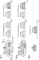
- FIG. 1 shows an example of an operation mode of a radio communication system (LTE-U) that operates LTE in an unlicensed band.
- LTE-U radio communication system
- CA Carrier Aggregation
- DC Dual Connectivity
- SA Stand-Alone
- FIG. 1A shows a scenario in which carrier aggregation (CA) is applied using a license band and an unlicensed band.
- CA is a technology for integrating a plurality of frequency blocks (also referred to as component carrier (CC), carrier, cell, etc.) to increase the bandwidth.
- CC component carrier
- Each CC has, for example, a maximum bandwidth of 20 MHz, and when a maximum of five CCs are integrated, a wide band of maximum 100 MHz is realized.
- FIG. 1A shows a case where CA is applied to a macro cell and / or a small cell using a license band and a small cell using an unlicensed band.
- a scheduler of one radio base station controls scheduling of a plurality of CCs. From this, CA may be called CA in a base station (intra-eNB CA).
- a small cell using an unlicensed band may use a carrier dedicated to DL transmission (scenario 1A) or a TDD carrier (scenario 1B).
- a carrier used exclusively for DL transmission is also referred to as an additional downlink (SDL).
- SDL additional downlink
- FDD and / or TDD can be used.
- the license band and the unlicensed band can be configured to be transmitted and received from one transmission / reception point (for example, a radio base station) (co-located).
- the transmission / reception point for example, LTE / LTE-U base station
- the transmission / reception point can communicate with the user terminal using both the license band and the unlicensed band.
- a configuration (non-co-located) for transmitting and receiving license bands and unlicensed bands from different transmission / reception points for example, RRH (Remote Radio Head) connected to one radio base station and the other radio base station
- RRH Remote Radio Head
- FIG. 1B shows a scenario in which dual connectivity (DC) is applied using a license band and an unlicensed band.
- DC is the same as CA in that a plurality of CCs (or cells) are integrated to widen the bandwidth.
- CA presupposes that CC (or cells) are connected by ideal backhaul and that cooperative control with a very small delay time is possible, whereas in DC, delay time is ignored between cells. It is assumed that connection is not possible with non-ideal backhaul.
- DC cells are operated by different base stations, and user terminals communicate by connecting to cells (or CCs) of different frequencies operated by different base stations.
- CC cells
- a plurality of schedulers are provided independently, and the plurality of schedulers control the scheduling of one or more cells (CC) each having jurisdiction over.
- DC may be called CA between base stations (inter-eNB CA).
- Inter-eNB CA base stations
- Intra-eNB CA carrier aggregation
- FIG. 1B shows a case where a macro cell using a license band and a small cell using an unlicensed band apply DC.
- the small cell using the unlicensed band may use a carrier dedicated to DL transmission (scenario 2A) or a TDD carrier (scenario 2B).
- FDD and / or TDD can be used.
- a stand-alone in which a cell that operates LTE using an unlicensed band operates alone is applied.
- stand-alone means that communication with a terminal can be realized without applying CA or DC.
- the unlicensed band can be operated on the TDD carrier (scenario 3).
- FIG. 2 shows an example of an operation mode of a radio communication system (LTE-U) that operates LTE in an unlicensed band.
- the license band CC (macro cell) is the primary cell (PCell)
- the unlicensed band CC (small cell) is the secondary cell (SCell).
- the primary cell (PCell) is a cell that manages RRC connection and handover when performing CA / DC, and is a cell that requires UL transmission of data, feedback signals, and the like from user terminals.
- the primary cell is always set for both the upper and lower links.
- the secondary cell (SCell) is another cell that is set in addition to the primary cell when applying CA / DC.
- a secondary cell can set only a downlink, and can also set up-and-down link simultaneously.
- LAA Licensed-Assisted Access
- LAA-LTE LAA-LTE
- systems that operate LTE / LTE-A in an unlicensed band may be collectively referred to as “LAA”, “LTE-U”, “U-LTE”, and the like.
- the license band LTE and the unlicensed band LTE cooperate to communicate with the user terminal.
- a transmission point using a license band for example, a radio base station
- a transmission point using an unlicensed band are separated, they are connected by a backhaul link (for example, an optical fiber or an X2 interface).
- a backhaul link for example, an optical fiber or an X2 interface.
- the unlicensed band is not limited to use by a specific operator. For this reason, the frequency band used in the LTE-U of a certain operator may overlap with the frequency band used in another operator's LAA system or Wi-Fi system.
- CSMA / CA Carrier Sense Multiple Access / Collision based on LBT (Listen Before Talk) mechanism is used to avoid collision of transmission signals of user terminals, access points, etc. Avoidance
- CSMA / CA Carrier Sense Multiple Access / Collision based on LBT (Listen Before Talk) mechanism is used to avoid collision of transmission signals of user terminals, access points, etc. Avoidance
- listening CCA: Clear Channel Assessment
- TP Transmission Point
- AP Access Point
- STA Wi-Fi terminal
- an LBT is also required in an LTE / LTE-A system (for example, an LAA system) operated in an unlicensed band.
- LBT LBT
- interference between LAA and Wi-Fi can be avoided.
- interference between LAA systems can be avoided. Even in the case where control of connectable user terminals is performed independently for each operator who operates the LAA system, interference can be reduced without grasping each control content by the LBT.
- an LTE-U base station and / or a user terminal performs listening (LBT) before transmitting a signal in an unlicensed band cell, and performs other systems (eg, Wi-Fi) or another LAA. If no signal from the transmission point is detected, communication is performed in the unlicensed band. For example, when the received power measured by the LBT is equal to or less than a predetermined threshold, it is determined that the channel is in an idle state (LBT_idle) and transmission is performed. In other words, “the channel is free” means that the channel is not occupied by a predetermined system, and the channel is clear or the channel is free.
- a signal from another system or another LAA transmission point is detected as a result of listening, (1) transition to another carrier by DFS (Dynamic Frequency Selection), (2) transmission power control (TPC) ), (3) waiting (stopping) transmission, and the like.
- DFS Dynamic Frequency Selection
- TPC transmission power control
- LBT_busy the channel is busy
- the channel can be used only after a predetermined back-off time has elapsed. Note that the method of determining whether the channel is free / busy by LBT is not limited to this.
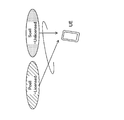
- FIG. 3 is an explanatory diagram showing the subject of LBT operation in a system that operates LTE / LTE-A in an unlicensed band.
- FIG. 3 shows a radio base station (eNB) that forms an unlicensed band cell, a user terminal (UE), and a downlink (DL) / uplink (UL) between them.
- eNB radio base station
- UE user terminal
- DL downlink
- UL uplink
- listening LBT
- FIG. 3A is an example in which an eNB performs LBT for both DL and UL.
- FIG. 3B is an example in which the transmission side performs LBT.
- LBT is performed by the eNB during DL transmission and by the UE during UL transmission.
- the LBT for UL implemented by the user terminal is also referred to as UL-LBT.
- UL-LBT it is considered that the interference state of the unlicensed band in the user terminal can be properly grasped.
- a frame configuration suitable for UL-LBT has not yet been proposed. In particular, if the subframe for sensing the LBT and the length of the sensing time are not set appropriately, the occurrence of UL signal interference may not be suppressed appropriately.
- the present inventors have conceived that, in a system that operates LTE / LTE-A in an unlicensed band, when a user terminal implements LBT, an appropriate configuration (sensing pattern) of sensing by LBT is set. did. Specifically, the present inventors have found that LBT is performed using a predetermined subframe as a sensing subframe based on a sensing pattern. In addition, the present inventors have found that the length of each period (such as a period for performing LBT) included in the sensing subframe is appropriately set.
- the subframe for sensing LBT and the length of sensing time can be set appropriately, and the occurrence of UL signal interference can be suppressed in the LTE system in the unlicensed band.
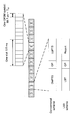
- FIG. 4 is a diagram illustrating an example of a frame configuration for LBT in a system that operates LTE / LTE-A in an unlicensed band.
- One subframe (1 ms) is composed of two slots, and one slot corresponds to 0.5 ms.
- One slot is composed of 7 OFDM symbols (6 symbols when the extended cyclic prefix is used), and one OFDM symbol corresponds to 66.7 ⁇ s + T CP (T CP : cyclic prefix length).
- each subframe indicates the type of subframe.
- “D” is a downlink (DL) subframe
- “U” is an uplink (UL) subframe
- “S” is a special subframe.
- DL downlink
- U is an uplink
- S is a special subframe.
- DL downlink
- U is an uplink
- S is a special subframe.
- a subframe in which sensing by LBT is performed also referred to as a sensing subframe
- the subframe configuration (order of arrangement of D, U, and S) in FIG. 4 is an example, and is not limited thereto.
- the special subframe in the conventional (Rel. 11) TDD UL / DL configuration (TDD UL / DL configuration) is composed of DwPTS (Downlink Pilot TimeSlot), GP (Guard Period), and UpPTS (Uplink Pilot TimeSlot).
- the sensing subframe in the present invention is composed of an LBT (LBT period), a GP (Guard Period), and a Report (report period). That is, since the sensing subframe configuration in the present invention is similar to the conventional special subframe configuration, the mounting cost of the user terminal can be reduced.
- the LBT period is used for the user terminal to detect the channel state. Specifically, in the LBT period, the user terminal performs listening (LBT). Here, unlike the special subframe, the user terminal does not have to try to receive and demodulate / decode PDSCH (Physical Downlink Shared Channel) in the sensing subframe.
- LBT listening
- PDSCH Physical Downlink Shared Channel
- GP is used as a guard period for the user terminal to switch from listening to report transmission. Further, the cell coverage radius of the serving cell is determined according to the length of the GP. If it is desired to increase the cell radius, a relatively long GP is required. On the other hand, when the cell radius is small, a short GP is sufficient. That is, GP is a guard period for switching between transmission and reception.
- the report period is a period for transmitting feedback information for transmission in the UL subframe after the sensing subframe.
- the feedback information is used for the user terminal to transmit the PUSCH and for the radio base station to receive the PUSCH. That is, it is useful information regarding PUSCH transmission.
- the useful information candidates include a scheduling request (SR) / random access preamble (RAP). According to these, UL grant can be requested and data transmission can be performed after sensing.
- useful information candidates include parameters related to PUSCH demodulation, such as resource blocks (RB) and MCS (Modulation and Coding Scheme). By using these, it is possible to perform data transmission after sensing without using the UL grant.
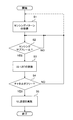
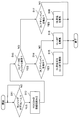
- FIG. 5 is a flowchart showing an example of UL-LBT processing of the user terminal according to the present invention.
- the user terminal acquires a sensing pattern (step S1). As will be described later, the user terminal acquires the sensing pattern by implicit or explicit notification, or calculates and acquires it according to a predetermined rule.
- the sensing pattern is information relating to the configuration of sensing by LBT.
- the sensing pattern is information related to the timing at which the user terminal performs LBT.
- the sensing pattern is composed of, for example, a combination of a sensing subframe and a period for sensing (also referred to as a sensing subframe period or a sensing period).
- the sensing pattern may be expressed as (“subframe corresponding to sensing subframe”, “sensing cycle”).
- a sensing pattern when sensing is performed every 1 ms in an arbitrary subframe may be expressed as (arbitrary subframe, 1 ms).
- a sensing pattern is not restricted to the above-mentioned structure.
- the user terminal determines whether or not the current subframe is a sensing subframe based on the sensing pattern (step S2). If the current subframe is not a sensing subframe (step S2-NO), step S2 is performed again in the next subframe.
- step S3 If the current subframe is a sensing subframe (step S2-YES), UL-LBT is performed (step S3). Then, based on the UL-LBT result, it is determined whether or not the channel is free (step S4). If it is determined that the channel is not free (step S4-NO), step S2 is performed again in the next subframe.
- step S1 When the sensing pattern is calculated by the user terminal in step S1, when it is determined that the channel is not free, step S1 may be performed again (dotted line in FIG. 5).
- step S4-YES If it is determined that the channel is free (step S4-YES), UL transmission is performed in the subsequent UL subframe (step S5).
- the present invention mainly relates to steps S1-S3 in FIG.
- the sensing pattern acquisition method in step S1 will be described in detail in the first and second embodiments.
- the sensing pattern is associated with a TDD UL / DL configuration.
- the first embodiment can be applied when an unlicensed band for performing LBT is a TDD carrier.
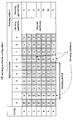
- FIG. 6 is a diagram illustrating an example of association between a TDD UL / DL configuration and a sensing pattern.
- Config.” In FIG. 6 indicates a TDD UL / DL configuration, and “Subframe index” indicates a subframe type corresponding to each UL / DL configuration.
- D indicates a downlink (DL) subframe
- U indicates an uplink (UL) subframe
- S indicates a special subframe or a sensing subframe.
- the special subframe can be regarded as a DL subframe, in other words, in FIG. 6, the DL subframe adjacent to the UL subframe (immediately before) is set as the sensing subframe. Therefore, in the UL / DL configuration ⁇ 0, 1, 2, 6 ⁇ , the sensing cycle is 5 ms, and in the UL / DL configuration 3-5, the sensing cycle is 10 ms. Also, under UL / DL configuration 0-6, the number of UL subframes following the sensing subframe is 1-3, so the channel occupation time based on the LBT result is 1-3 ms.
- the radio base station notifies the user terminal of the sensing pattern using higher layer signaling (for example, RRC signaling) and broadcast information (for example, SIB1).
- the sensing pattern may be notified together with the UL / DL configuration, or may be implicitly notified by notification of the UL / DL configuration when associated with the UL / DL configuration in advance.
- the sensing pattern (special subframe, 5 ms) may be explicitly notified, or implicitly (special subframe by the notification of Config.2 as UL / DL configuration) 5 ms) may be recognized by the user terminal.
- the UL / DL configuration may use a different configuration other than the UL / DL configuration 0-6 shown in FIG. 6. In this case, the DL subframe adjacent to the UL subframe (immediately before) is used as the sensing subframe. It is good also as a frame.
- Method 1 the setting for the special subframe of the conventional (LTE Rel. 11) is used for the sensing subframe configuration. Specifically, in Method 1, the lengths of LBT, GP, and Report in the sensing subframe are treated as the lengths of DwPTS, GP, and UpPTS in the special subframe, respectively.
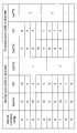
- FIG. 7 is a diagram illustrating an example of a special subframe configuration in TDD.
- “Special subframe config.” Indicates a special subframe configuration.
- the unit of length of DwPTS, GP and UpPTS is a symbol.
- the lengths of LBT, GP, and Report in the sensing subframe are 3, 10 and 1 OFDM symbols, respectively.
- the special subframe configuration is not limited to configurations 0-9 shown in FIG.
- Each special subframe configuration defines the length of DwPTS, GP and UpPTS.
- Each configuration defines a case where a standard cyclic prefix is used (symbol length of one subframe is 14) and a case where an extended cyclic prefix is used (symbol length of one subframe is 12).
- Each configuration may define at least two parameters, and one parameter may be omitted.
- DwPTS and UpPTS may be defined, and GP need not be defined. In this case, the user terminal can determine the length of the GP based on the symbol length, DwPTS, and UpPTS.
- the GP time is as short as possible. Specifically, it is preferably 3 symbols or less. That is, the sensing subframe configuration is ⁇ 2, 3, 4, 6, 7, 8 ⁇ (when using a standard cyclic prefix) or ⁇ 1, 2, 3, 5, 6 ⁇ (extended cycle) of the special subframe configuration. It is preferable to select from (when using a click prefix).
- Method 2 defines a new sensing subframe configuration.
- the lengths of LBT, GP, and Report in the sensing subframe can be set independently of the lengths of DwPTS, GP, and UpPTS in the special subframe, respectively.
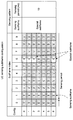
- FIG. 8 is a diagram illustrating an example of a sensing subframe configuration in TDD.
- “Sensing subframe config.” Indicates a sensing subframe configuration.
- the unit of length of DwPTS, GP and UpPTS is a symbol.
- the sensing subframe configuration is not limited to the configurations 0-9 shown in FIG.
- the sensing subframe configuration may use LBT, GP, and Report lengths different from those in FIG.
- the sensing subframe configuration is preferably configured to include many GPs having a smaller value than the GP of the conventional special subframe configuration (Rel. 11). Thereby, it is possible to set a guard period more suitable for a small cell having a relatively small coverage radius.
- the sensing subframe configuration it is preferable to configure the sensing subframe configuration to include a larger number of reports than the UpPTS of the conventional (Rel. 11) special subframe configuration. Accordingly, the report period is extended, and more useful information (for example, NAV (Network Allocation Vector), BSR (Buffer Status Report)) can be transmitted.
- NAV Network Allocation Vector
- BSR Buffer Status Report
- different time, frequency, and code resources can be allocated among the user terminals. It becomes possible to reduce.
- sensing subframe configuration to be applied may be notified to the user terminal by higher layer signaling (for example, RRC signaling) and / or broadcast information (for example, SIB1).
- higher layer signaling for example, RRC signaling
- SIB1 broadcast information
- a radio frame has a plurality of sensing subframes
- different sensing subframe configurations may be used for each sensing subframe.
- the special subframe configuration applied to the radio frame and the sensing subframe configuration may be selected to be different.
- the example which uses all the special sub-frames as a sensing sub-frame was shown in FIG. 6, it is not restricted to this.
- a configuration may be adopted in which some special subframes are used as sensing subframes.
- a special subframe that is not used as a sensing subframe can be used as a DL subframe. Therefore, while maintaining a relatively short sensing period (for example, 10 subframes or less), DL throughput can be reduced. Reduction can be suppressed.
- FIG. 9 is a diagram illustrating an example of association between a TDD UL / DL configuration and a sensing pattern.
- the special subframe in subframe 1 is detected as a sensing subframe.
- the special subframe in subframe 6 is used as it is as a special subframe.
- the sensing period is 10 ms.
- the allocation policy of which special subframe is used as a sensing subframe is not limited to this.
- the special subframe in subframe 6 is used as a sensing subframe
- the special subframe in subframe 1 is used as a special subframe as it is. It is good also as composition to do.
- a special subframe that is different for each radio frame may be used as a sensing subframe.
- the sensing cycle may be longer than 10 subframes, and the wireless frame may not include the sensing subframes.
- the sensing period may be 20 ms, 40 ms, 80 ms, or the like.
- the sensing period may be notified to the user terminal by higher layer signaling (for example, RRC signaling) and / or broadcast information (for example, SIB1).
- the sensing pattern is not associated with a TDD UL / DL configuration.
- the user terminal implicitly determines and uses a sensing pattern, or uses a sensing pattern that is explicitly notified.
- FIG. 10 is a diagram illustrating an example of a sensing pattern that is implicitly set.
- the sensing cycle may be one subframe, and sensing may be performed whenever transmission data is included.
- the sensing pattern is (arbitrary subframe, 1 ms).
- the sensing result in subframes 0 and 1 is busy, and the result in subframe 2 is free. Therefore, the user terminal can perform transmission in subframe 3, for example.
- the configuration in which sensing is performed for each subframe allows transmission with low delay because the waiting time for sensing is short, but power consumption increases because sensing is performed with high frequency.
- the sensing cycle may be changed according to the number of times of sensing performed to transmit the data. For example, when the sensing result is busy, the user terminal changes the sensing period by determining the next sensing subframe based on Table 1 below.
- i indicates the number of times of sensing performed (number of times of waiting for transmission)
- SF current indicates the current subframe.
- the result of sensing in subframe 8 is free, and the user terminal can start the transmission process.
- the configuration in which the sensing period is changed according to the number of sensing trials can realize a trade-off between delay and power consumption.
- the implicit sensing pattern is not limited to these.
- a configuration may be adopted in which sensing is performed every several subframes.
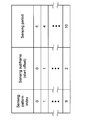
- FIG. 11 is a diagram illustrating an example of a sensing pattern that is explicitly notified.
- “Sensing pattern index” indicates a sensing pattern number (index).
- FIG. 11 shows a sensing pattern that assumes periodic sensing.
- One sensing pattern includes a sensing subframe start offset (that is, the smallest sensing subframe number in one frame), and a sensing period. And associated with. For example, in FIG. 11, when the sensing pattern index is 0, the sensing subframe is 0 and the sensing period is 6.
- the sensing pattern may be cell specific.
- the radio base station forming each cell notifies the user terminal in the cell of the sensing pattern specific to the cell using broadcast information (for example, SIB1).
- the sensing pattern may be unique to the user terminal.
- the radio base station notifies the user terminal of a sensing pattern specific to the user terminal using higher layer signaling (for example, RRC signaling).
- FIG. 12 is a diagram illustrating an example of a case where a sensing pattern to be explicitly notified is cell-specific.
- UE 1 is connected to Cell 1 of the unlicensed band
- UE 2 is connected to Cell 2 of the unlicensed band.
- Cell 1 notifies UE 1 which is a subordinate user terminal of sensing pattern 0 (see FIG. 11) which is a sensing pattern of the own cell
- Cell 2 is UE 2 which is a subordinate user terminal and sense pattern of the own cell.
- sensing pattern 1 see FIG. 11).
- FIG. 13 is a diagram illustrating an example of a case where the sensing pattern that is explicitly notified is unique to the user terminal.
- UE 1 and UE 2 are connected to Cell 0 of the license band and Cell 1 of the unlicensed band.
- Cell 0 notifies UE 1 and UE 2 that are subordinate user terminals of sensing patterns 0 and 1 (see FIG. 11) that are the respective sensing patterns.
- it is good also as a structure which notifies the sensing pattern specific to a user terminal from the cell of an unlicensed band.
- the user terminal is not limited to the combination defined by the sensing pattern, and can perform appropriate sensing.
- the sensing subframe configuration may include a configuration including LBT, GP, and Report.
- the user terminal determines the length of each period in the sensing subframe based on the special subframe configuration in TDD or the newly defined sensing subframe configuration. Also good.
- the sensing subframe configuration in the second embodiment is not limited to a configuration including LBT, GP, and Report. For example, all sensing subframes may be LBT times.
- the start offset of the sensing subframe, the sensing cycle, and the sensing subframe configuration may also be notified for each cell using broadcast information (for example, SIB1), or using higher layer signaling (for example, RRC signaling). You may notify for every user terminal. These notifications are preferably performed for each cell when the sensing pattern is cell-specific, and for each user terminal when the sensing pattern is specific for the user terminal.
- broadcast information for example, SIB1
- RRC signaling for example, RRC signaling
- the sensing pattern, sensing period, sensing time of the LBT, and the like are determined so as to satisfy predetermined regulations (for example, regulations by countries and regions) regarding the LBT.
- predetermined regulations for example, regulations by countries and regions
- the sensing time, channel occupation time, and the like are determined so that flexible and fair use of the bandwidth is realized with other systems using the unlicensed band.
- the channel occupation time is required to be within a range of a minimum of 1 ms and a maximum of 10 ms.
- the present inventors have further conceived of switching the sensing subframe according to traffic. Specifically, it has been found that the sensing subframe is used as a conventional special subframe when there is DL traffic, and is used as a sensing subframe when there is UL traffic. According to this, it is possible to further effectively use radio resources.
- FIG. 14 is a flowchart illustrating an example of sensing subframe switching processing according to the third embodiment.
- the user terminal determines whether or not the current subframe is a sensing subframe (step S11). If it is not a sensing subframe (step S11-NO), the process waits until the next subframe and executes step S11 again.
- step S11-YES If the current subframe is a sensing subframe (step S11-YES), first read PCFICH (Physical Control Format Indicator Channel), and in a predetermined OFDM symbol period (for example, 1 to 2 OFDM symbol periods) based on PCFICH Attempt to receive PDCCH (Physical Downlink Control Channel) (step S12).
- PCFICH Physical Control Format Indicator Channel
- PDCCH Physical Downlink Control Channel
- step S12 even if PCFICH reception is skipped and PDCCH reception is attempted in a predetermined OFDM symbol period (for example, 1-2 OFDM symbol period) set in advance by higher layer signaling (for example, RRC signaling). Good.
- the user terminal determines whether UL data is held in the buffer (step S13). When it is determined that the UL data is held (step S13-YES), it is further determined whether or not a DL assignment (DL assignment) indicating the PDSCH addressed to itself is detected as a result of step S12 (step S14). ). If it is determined that a DL assignment has been detected (step S14—YES), one of the following is executed (step S15): (Alt. 1) Recognizing the current subframe as a special subframe, pending the UL-LBT, and performing DL reception. (Alt. 2) Recognize the current subframe as a sensing subframe, give up DL reception, and perform UL-LBT.
- the PDSCH is received and demodulated in the same manner as DwPTS in the conventional special subframe.
- Alt. 2 it is preferable that a NACK is transmitted at a predetermined timing in order to notify the radio base station that DL reception has been given up.
- DL reception will fail in the subframe, but detection of DL assignment itself has been completed, so if NACK can be transmitted at a predetermined timing, retransmission can be performed at a future transmission / reception opportunity. Therefore, no particular problem occurs.
- step S14-NO when it is determined that the DL assignment is not detected (step S14-NO), the current subframe is recognized as a sensing subframe, and UL-LBT is performed (step S16).
- step S17 If it is determined that the UL data is not retained (step S13—NO), it is further determined whether or not a DL assignment indicating the PDSCH addressed to itself is detected (step S17). When it is determined that a DL assignment has been detected (step S17-YES), the current subframe is recognized as a special subframe and DL reception is performed (step S18).
- step S17—NO when it is determined that the DL assignment is not detected (step S17—NO), in the example of FIG. 14, nothing is done (transmission / reception or sensing is not performed), but this is not a limitation.
- UL-LBT may be performed by recognizing the current subframe as a sensing subframe.
- step S15 Alt. Is determined according to whether the UL data held in the buffer is control information. 1 and Alt. ⁇ / 2> The operation with 2 may be switched. For example, when UL data including control information is included, DL reception is abandoned and UL-LBT is executed. Otherwise, UL-LBT is suspended and DL reception may be prioritized. Thereby, the user terminal can transmit control information important for communication as soon as possible.
- the UL-LBT in the above steps S15 and S16 may be implemented when a UL grant instructing PUSCH transmission is detected upon reception of the PDCCH in step S12.
- the sensing subframe is set in advance as in the first and second embodiments, but the present invention is not limited to this.
- the user terminal determines whether or not the current subframe is a special subframe in step S11. If the sensing subframe is a special subframe, the processing after step S12 is performed. It is good also as a structure to implement.
- a predetermined subframe can be used as a sensing subframe or a special subframe in accordance with upper and lower traffic, so that radio resources can be used more flexibly.
- the radio base station can transmit a UL grant instructing to the user terminal.
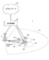
- FIG. 15 is a diagram illustrating an example of a schematic configuration of a wireless communication system according to an embodiment of the present invention.
- the radio communication system shown in FIG. 15 is a system including, for example, an LTE system, SUPER 3G, LTE-A system, and the like.
- carrier aggregation (CA) and / or dual connectivity (DC) in which a plurality of basic frequency blocks (component carriers) having the system bandwidth of the LTE system as one unit can be applied.
- the wireless communication system shown in FIG. 15 has a wireless base station (for example, LTE-U base station) that can use an unlicensed band.
- This wireless communication system may be called IMT-Advanced, or may be called 4G, FRA (Future Radio Access), or the like.
- a radio communication system 1 shown in FIG. 15 includes a radio base station 11 that forms a macro cell C1, and radio base stations 12a to 12c that are arranged in the macro cell C1 and form a small cell C2 that is narrower than the macro cell C1. .
- the user terminal 20 is arrange
- the user terminal 20 can be connected to both the radio base station 11 and the radio base station 12. It is assumed that the user terminal 20 uses the macro cell C1 and the small cell C2 that use different frequencies simultaneously by CA or DC. For example, assist information (for example, DL signal configuration) regarding the radio base station 12 (for example, LTE-U base station) that uses the unlicensed band is transmitted from the radio base station 11 that uses the license band to the user terminal 20. can do. Further, when CA is performed in the license band and the unlicensed band, it is possible to adopt a configuration in which one radio base station (for example, the radio base station 11) controls the schedules of the license band cell and the unlicensed band cell.
- assist information for example, DL signal configuration
- LTE-U base station LTE-U base station
- the user terminal 20 may be connected to the radio base station 12 without being connected to the radio base station 11.
- the wireless base station 12 using the unlicensed band may be connected to the user terminal 20 in a stand-alone manner.
- the radio base station 12 controls the schedule of the unlicensed band cell.
- Communication between the user terminal 20 and the radio base station 11 can be performed using a carrier having a relatively low frequency band (for example, 2 GHz) and a narrow bandwidth (referred to as an existing carrier or a legacy carrier).
- a carrier having a relatively high frequency band for example, 3.5 GHz, 5 GHz, etc.
- a wide bandwidth may be used between the user terminal 20 and the radio base station 12, or The same carrier may be used.
- a wired connection optical fiber, X2 interface, etc.
- a wireless connection may be employed between the wireless base station 11 and the wireless base station 12 (or between the two wireless base stations 12).
- the radio base station 11 and each radio base station 12 are connected to the higher station apparatus 30 and connected to the core network 40 via the higher station apparatus 30.
- the upper station device 30 includes, for example, an access gateway device, a radio network controller (RNC), a mobility management entity (MME), and the like, but is not limited thereto.
- RNC radio network controller
- MME mobility management entity
- Each radio base station 12 may be connected to the higher station apparatus 30 via the radio base station 11.
- the radio base station 11 is a radio base station having a relatively wide coverage, and may be called a macro base station, an aggregation node, an eNB (eNodeB), a transmission / reception point, or the like.
- the radio base station 12 is a radio base station having local coverage, and includes a small base station, a micro base station, a pico base station, a femto base station, a HeNB (Home eNodeB), an RRH (Remote Radio Head), and transmission / reception. It may be called a point.
- the radio base stations 11 and 12 are not distinguished, they are collectively referred to as a radio base station 10.
- Each user terminal 20 is a terminal that supports various communication schemes such as LTE and LTE-A, and may include not only a mobile communication terminal but also a fixed communication terminal.
- OFDMA Orthogonal Frequency Division Multiple Access
- SC-FDMA Single Carrier Frequency Division Multiple Access
- OFDMA is a multi-carrier transmission scheme that performs communication by dividing a frequency band into a plurality of narrow frequency bands (subcarriers) and mapping data to each subcarrier.
- SC-FDMA is a single-carrier transmission scheme that reduces interference between terminals by dividing the system bandwidth into bands consisting of one or continuous resource blocks for each terminal and using a plurality of terminals with mutually different bands. is there.
- the uplink and downlink radio access methods are not limited to these combinations.
- downlink channels include a downlink shared channel (PDSCH) shared by each user terminal 20, a broadcast channel (PBCH: Physical Broadcast Channel), a downlink L1 / L2 control channel, and the like. Used. User data, higher layer control information, and predetermined SIB (System Information Block) are transmitted by PDSCH. Moreover, MIB (Master Information Block) etc. are transmitted by PBCH.
- PDSCH downlink shared channel
- PBCH Physical Broadcast Channel
- SIB System Information Block
- MIB Master Information Block
- Downlink L1 / L2 control channels include PDCCH (Physical Downlink Control Channel), EPDCCH (Enhanced Physical Downlink Control Channel), PCFICH (Physical Control Format Indicator Channel), PHICH (Physical Hybrid-ARQ Indicator Channel), and the like.
- Downlink control information (DCI: Downlink Control Information) including scheduling information of PDSCH and PUSCH is transmitted by PDCCH.
- the number of OFDM symbols used for PDCCH is transmitted by PCFICH.
- the HAICH transmission confirmation signal (ACK / NACK) for PUSCH is transmitted by PHICH.
- the EPDCCH is frequency division multiplexed with a PDSCH (downlink shared data channel) and may be used to transmit DCI or the like in the same manner as the PDCCH.
- an uplink shared channel (PUSCH: Physical Uplink Shared Channel), an uplink control channel (PUCCH: Physical Uplink Control Channel), and a random access channel (PRACH) shared by each user terminal 20 are used. Physical Random Access Channel) is used. User data and higher layer control information are transmitted by PUSCH. Also, downlink radio quality information (CQI: Channel Quality Indicator), a delivery confirmation signal, and the like are transmitted by PUCCH.
- CQI Channel Quality Indicator
- a delivery confirmation signal and the like are transmitted by PUCCH.
- a random access preamble (RA preamble) for establishing a connection with the cell is transmitted by the PRACH.
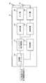
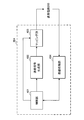
- FIG. 16 is a diagram illustrating an example of the overall configuration of the radio base station 10 (including the radio base stations 11 and 12) according to the present embodiment.
- the radio base station 10 includes a plurality of transmission / reception antennas 101 for MIMO transmission, an amplifier unit 102, a transmission / reception unit 103, a baseband signal processing unit 104, a call processing unit 105, and a transmission path interface 106.
- the transmission / reception unit 103 may include a transmission unit and a reception unit.
- User data transmitted from the radio base station 10 to the user terminal 20 via the downlink is input from the higher station apparatus 30 to the baseband signal processing unit 104 via the transmission path interface 106.
- PDCP Packet Data Convergence Protocol
- RLC Radio Link Control
- MAC Medium Access
- Retransmission control for example, HARQ (Hybrid Automatic Repeat reQuest) transmission processing
- HARQ Hybrid Automatic Repeat reQuest
- the downlink control signal is also subjected to transmission processing such as channel coding and inverse fast Fourier transform, and transferred to each transmitting / receiving unit 103.
- the baseband signal processing unit 104 notifies the user terminal 20 of control information (system information) for communication in the cell by higher layer signaling (for example, RRC signaling, broadcast information, etc.).
- the information for communication in the cell includes, for example, the system bandwidth in the uplink and the system bandwidth in the downlink.
- assist information regarding unlicensed band communication may be transmitted from the radio base station (for example, the radio base station 11) to the user terminal 20 in the license band.
- Each transmission / reception unit 103 converts the baseband signal output by precoding from the baseband signal processing unit 104 for each antenna to a radio frequency band and transmits the converted signal.
- the radio frequency signal frequency-converted by the transmission / reception unit 103 is amplified by the amplifier unit 102 and transmitted from the transmission / reception antenna 101.
- the transmission / reception unit 103 can be a transmitter / receiver, a transmission / reception circuit, or a transmission / reception device described based on common recognition in the technical field according to the present invention.
- the radio frequency signal received by each transmitting / receiving antenna 101 is amplified by the amplifier unit 102.
- Each transmitting / receiving unit 103 receives the upstream signal amplified by the amplifier unit 102.
- the transmission / reception unit 103 converts the frequency of the received signal into a baseband signal and outputs it to the baseband signal processing unit 104.
- the baseband signal processing unit 104 performs fast Fourier transform (FFT) processing, inverse discrete Fourier transform (IDFT: Inverse Discrete Fourier Transform) processing, and error correction on user data included in the input upstream signal.
- FFT fast Fourier transform
- IDFT inverse discrete Fourier transform
- Decoding, MAC retransmission control reception processing, RLC layer, and PDCP layer reception processing are performed and transferred to the upper station apparatus 30 via the transmission path interface 106.
- the call processing unit 105 performs call processing such as communication channel setting and release, state management of the radio base station 10, and radio resource management.
- the transmission path interface 106 transmits and receives signals to and from the higher station apparatus 30 via a predetermined interface.
- the transmission path interface 106 may transmit and receive signals (backhaul signaling) to and from the adjacent radio base station 10 via an inter-base station interface (for example, an optical fiber or an X2 interface).
- an inter-base station interface for example, an optical fiber or an X2 interface.
- the transmission path interface 106 may transmit and receive a TDD UL / DL configuration, a special subframe configuration, a sensing subframe configuration, a sensing pattern, and the like with the adjacent radio base station 10.
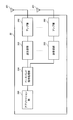
- FIG. 17 is a diagram illustrating an example of a functional configuration of the radio base station according to the present embodiment. Note that FIG. 17 mainly shows functional blocks of characteristic portions in the present embodiment, and the wireless base station 10 also has other functional blocks necessary for wireless communication.
- the baseband signal processing unit 104 included in the radio base station 10 includes a control unit (scheduler) 301, a transmission signal generation unit 302, a mapping unit 303, and a reception processing unit 304. ing.
- the control unit (scheduler) 301 controls scheduling (for example, resource allocation) of downlink data signals transmitted on PDSCH, downlink control signals transmitted on PDCCH and / or enhanced PDCCH (EPDCCH). It also controls scheduling of system information, synchronization signals, downlink reference signals such as CRS (Cell-specific Reference Signal) and CSI-RS (Channel State Information Reference Signal). It also controls scheduling such as uplink reference signals, uplink data signals transmitted on PUSCH, uplink control signals transmitted on PUCCH and / or PUSCH, and RA preambles transmitted on PRACH.
- scheduling for example, resource allocation of downlink data signals transmitted on PDSCH, downlink control signals transmitted on PDCCH and / or enhanced PDCCH (EPDCCH). It also controls scheduling of system information, synchronization signals, downlink reference signals such as CRS (Cell-specific Reference Signal) and CSI-RS (Channel State Information Reference Signal). It also controls scheduling such as uplink reference signals, uplink data signals transmitted on PUSCH, uplink control
- control unit 301 When scheduling is performed by one control unit (scheduler) 301 for the license band and the unlicensed band, the control unit 301 controls communication between the license band cell and the unlicensed band cell.
- the control unit 301 may be a controller, a control circuit, or a control device described based on common recognition in the technical field according to the present invention.
- control unit 301 controls the sensing pattern and / or sensing subframe configuration used by the user terminal 20. For example, the control unit 301 may determine the sensing pattern in association with the TDD UL / DL configuration (first embodiment). Further, the control unit 301 may determine the sensing pattern without associating it with the TDD UL / DL configuration (second embodiment).
- control unit 301 determines the interference state of the radio base station 10 and / or the user terminal 20 by using the measurement result by the reception processing unit 304 and the feedback report from the user terminal 20 to determine the sensing pattern and / or Alternatively, the sensing subframe configuration may be determined. Also, the sensing pattern and / or sensing subframe configuration may be determined according to the number of user terminals in the cell, the transmission priority of each user terminal, and uplink / downlink traffic.
- the control unit 301 outputs the determined sensing pattern and / or sensing subframe configuration to the transmission signal generation unit 302, and controls the mapping unit 303 to map signals including these pieces of information.
- the sensing pattern or the like may be notified implicitly in association with other information, instead of being notified by an explicit signal.
- the transmission signal generation unit 302 generates a DL signal (downlink control signal, downlink data signal, downlink reference signal, etc.) based on an instruction from the control unit 301 and outputs the DL signal to the mapping unit 303. For example, based on an instruction from the control unit 301, the transmission signal generation unit 302 generates a DL assignment that notifies downlink signal allocation information and a UL grant that notifies uplink signal allocation information. Further, the downlink data signal is subjected to coding processing and modulation processing according to a coding rate, a modulation scheme, and the like determined based on channel state information (CSI) from each user terminal 20.
- the transmission signal generation unit 302 may be a signal generator or a signal generation circuit described based on common recognition in the technical field according to the present invention.
- the mapping unit 303 maps the downlink signal generated by the transmission signal generation unit 302 to a radio resource based on an instruction from the control unit 301, and outputs the radio signal to the transmission / reception unit 103.
- the mapping unit 303 can be a mapping circuit or a mapper described based on common recognition in the technical field according to the present invention.
- the reception processing unit 304 performs reception processing (for example, demapping, demodulation, decoding) on UL signals (for example, a delivery confirmation signal (HARQ-ACK), a data signal transmitted by PUSCH, etc.) transmitted from the user terminal. Etc.).
- the reception processing unit 304 may measure the received power (RSRP) and the channel state using the received signal.
- the processing result and the measurement result may be output to the control unit 301.
- the reception processing unit 304 can be a signal processing / measurement device or a signal processing / measurement circuit described based on common recognition in the technical field according to the present invention.
- reception processing unit 304 receives and demodulates the PUSCH with the radio resource indicated by the predetermined information based on the instruction from the control unit 301.
- FIG. 18 is a diagram illustrating an example of the overall configuration of the user terminal according to the present embodiment.
- the user terminal 20 includes a plurality of transmission / reception antennas 201 for MIMO transmission, an amplifier unit 202, a transmission / reception unit 203, a baseband signal processing unit 204, and an application unit 205.
- the transmission / reception unit 203 may include a transmission unit and a reception unit.
- the radio frequency signals received by the plurality of transmission / reception antennas 201 are each amplified by the amplifier unit 202.
- Each transmitting / receiving unit 203 receives the downlink signal amplified by the amplifier unit 202.
- the transmission / reception unit 203 converts the frequency of the received signal into a baseband signal and outputs it to the baseband signal processing unit 204.
- the transmission / reception unit 203 can be a transmitter / receiver, a transmission / reception circuit, or a transmission / reception device described based on common recognition in the technical field according to the present invention.
- the transmission / reception unit 203 can transmit / receive UL / DL signals in an unlicensed band.
- the transmission / reception unit 203 may be capable of transmitting / receiving UL / DL signals in a license band.
- the baseband signal processing unit 204 performs FFT processing, error correction decoding, retransmission control reception processing, and the like on the input baseband signal.
- the downlink user data is transferred to the application unit 205.
- the application unit 205 performs processing related to layers higher than the physical layer and the MAC layer.
- broadcast information in the downlink data is also transferred to the application unit 205.
- uplink user data is input from the application unit 205 to the baseband signal processing unit 204.
- the baseband signal processing unit 204 performs retransmission control transmission processing (for example, HARQ transmission processing), channel coding, precoding, discrete Fourier transform (DFT) processing, IFFT processing, and the like.
- the data is transferred to the transmission / reception unit 203.
- the transmission / reception unit 203 converts the baseband signal output from the baseband signal processing unit 204 into a radio frequency band and transmits it.
- the radio frequency signal frequency-converted by the transmission / reception unit 203 is amplified by the amplifier unit 202 and transmitted from the transmission / reception antenna 201.
- FIG. 19 is a diagram illustrating an example of a functional configuration of the user terminal according to the present embodiment. Note that FIG. 19 mainly shows functional blocks of characteristic portions in the present embodiment, and the user terminal 20 also has other functional blocks necessary for wireless communication.
- the baseband signal processing unit 204 included in the user terminal 20 includes a control unit 401, a transmission signal generation unit 402, a mapping unit 403, and a reception processing unit 404.
- the control unit 401 obtains, from the received signal processing unit 404, a downlink control signal (a signal transmitted by PDCCH / EPDCCH) and a downlink data signal (a signal transmitted by PDSCH) transmitted from the radio base station 10.
- the control unit 401 generates an uplink control signal (for example, an acknowledgment signal (HARQ-ACK)) or an uplink data signal based on a downlink control signal, a result of determining whether retransmission control is necessary for the downlink data signal, or the like.
- HARQ-ACK acknowledgment signal
- the control unit 401 controls the transmission signal generation unit 402 and the mapping unit 403.
- the control unit 401 may be a controller, a control circuit, or a control device described based on common recognition in the technical field according to the present invention.
- control unit 401 has a function of grasping the buffer amount of the UL data input from the application unit 205.
- the control unit 401 causes the reception processing unit 404 to perform UL-LBT in the sensing subframe. To control. Even when there is no UL data, the reception processing unit 404 may perform UL-LBT.
- control unit 401 may control to transmit useful information related to PUSCH transmission in the report period according to the result of the LBT input from the reception processing unit 404.
- the control unit 401 controls a predetermined subframe as a sensing subframe based on the sensing pattern. For example, the control unit 401 may grasp a sensing pattern from an explicit notification (first and second embodiments) or may implicitly grasp a sensing pattern (second embodiment). . For example, the control unit 401 may count the number of sensing trials in the reception processing unit 404 and calculate and acquire a sensing pattern based on the number of sensing trials (for example, Table 1).
- control unit 401 may switch whether to use each sensing subframe as a sensing subframe or a special subframe (third embodiment). For example, the control unit 401 controls the reception processing unit 404 so as to attempt to receive PDCCH in a predetermined OFDM symbol period based on PCFICH for a subframe specified as a sensing subframe. When the reception processing unit 404 notifies that the DL assignment is detected in the sensing subframe, the control unit 401 causes the reception processing unit 404 to perform DL reception or UL-LBT.
- the transmission signal generation unit 402 generates a UL signal (uplink control signal, uplink data signal, uplink reference signal, etc.) based on an instruction from the control unit 401, and outputs the UL signal to the mapping unit 403.
- the transmission signal generation unit 402 generates uplink control signals such as a delivery confirmation signal (HARQ-ACK) and channel state information (CSI) based on an instruction from the control unit 401.
- the transmission signal generation unit 402 generates an uplink data signal based on an instruction from the control unit 401.
- the control unit 401 instructs the transmission signal generation unit 402 to generate an uplink data signal.
- the transmission signal generation unit 402 can be a signal generator or a signal generation circuit described based on common recognition in the technical field according to the present invention.
- the mapping unit 403 maps the uplink signal generated by the transmission signal generation unit 402 to a radio resource based on an instruction from the control unit 401, and outputs the radio signal to the transmission / reception unit 203.
- the mapping unit 403 can be a mapping circuit or a mapper described based on common recognition in the technical field according to the present invention.
- the reception processing unit 404 performs a reception process (for example, a downlink control signal transmitted from the radio base station, a downlink data signal transmitted by the PDSCH, etc.) transmitted in the license band and the unlicensed band. Demapping, demodulation, decoding, etc.).
- the reception processing unit 404 outputs the TDD UL / DL configuration, special subframe configuration, sensing subframe configuration, sensing pattern, and the like from the radio base station 10 to the control unit 401. Further, the reception processing unit 404 may measure the received power (RSRP) and the channel state using the received signal. The processing result and the measurement result may be output to the control unit 401.
- the reception processing unit 404 may be a signal processing / measurement device or a signal processing / measurement circuit described based on common recognition in the technical field according to the present invention.
- the reception processing unit 404 Based on an instruction from the control unit 401, the reception processing unit 404 performs LBT in an unlicensed band using a predetermined subframe (for example, a special subframe) as a sensing subframe, and performs an LBT result (for example, a channel state). Is a clear result or a busy determination result) is output to the control unit 401.
- a predetermined subframe for example, a special subframe
- an LBT result for example, a channel state
- the reception processing unit 404 attempts to receive the PDCCH in a predetermined OFDM symbol section based on PCFICH for the subframe specified as the sensing subframe based on the instruction from the control unit 401.
- the reception processing unit 404 detects a DL assignment indicating the PDSCH addressed to the terminal itself, the reception processing unit 404 notifies the control unit 401 accordingly.
- each functional block is realized by one physically coupled device, or may be realized by two or more physically separated devices connected by wire or wirelessly and by a plurality of these devices. Good.
- radio base station 10 and the user terminal 20 are realized using hardware such as ASIC (Application Specific Integrated Circuit), PLD (Programmable Logic Device), and FPGA (Field Programmable Gate Array). May be.
- the radio base station 10 and the user terminal 20 may be realized by a computer apparatus including a processor (CPU), a communication interface for network connection, a memory, and a computer-readable storage medium holding a program. Good.
- the processor and memory are connected by a bus for communicating information.
- the computer-readable recording medium is a storage medium such as a flexible disk, a magneto-optical disk, a ROM, an EPROM, a CD-ROM, a RAM, and a hard disk.
- the program may be transmitted from a network via a telecommunication line.
- the radio base station 10 and the user terminal 20 may include an input device such as an input key and an output device such as a display.
- the functional configurations of the radio base station 10 and the user terminal 20 may be realized by the hardware described above, may be realized by a software module executed by a processor, or may be realized by a combination of both.
- the processor controls the entire user terminal by operating an operating system. Further, the processor reads programs, software modules and data from the storage medium into the memory, and executes various processes according to these.
- the program may be a program that causes a computer to execute the operations described in the above embodiments.
- the control unit 401 of the user terminal 20 may be realized by a control program stored in a memory and operated by a processor, and may be realized similarly for other functional blocks.
Abstract
Priority Applications (4)
| Application Number | Priority Date | Filing Date | Title |
|---|---|---|---|
| JP2016538231A JPWO2016017355A1 (ja) | 2014-07-31 | 2015-07-01 | ユーザ端末、無線基地局、無線通信方法及び無線通信システム |
| US15/500,635 US20170223550A1 (en) | 2014-07-31 | 2015-07-01 | User terminal, radio base station, radio communication method and radio communication system |
| CN201580041235.8A CN106576349A (zh) | 2014-07-31 | 2015-07-01 | 用户终端、无线基站、无线通信方法以及无线通信系统 |
| US16/244,969 US11218883B2 (en) | 2014-07-31 | 2019-01-10 | User terminal, radio base station, radio communication method and radio communication system |
Applications Claiming Priority (2)
| Application Number | Priority Date | Filing Date | Title |
|---|---|---|---|
| JP2014-156209 | 2014-07-31 | ||
| JP2014156209 | 2014-07-31 |
Related Child Applications (2)
| Application Number | Title | Priority Date | Filing Date |
|---|---|---|---|
| US15/500,635 A-371-Of-International US20170223550A1 (en) | 2014-07-31 | 2015-07-01 | User terminal, radio base station, radio communication method and radio communication system |
| US16/244,969 Continuation US11218883B2 (en) | 2014-07-31 | 2019-01-10 | User terminal, radio base station, radio communication method and radio communication system |
Publications (1)
| Publication Number | Publication Date |
|---|---|
| WO2016017355A1 true WO2016017355A1 (fr) | 2016-02-04 |
Family
ID=55217259
Family Applications (1)
| Application Number | Title | Priority Date | Filing Date |
|---|---|---|---|
| PCT/JP2015/068990 WO2016017355A1 (fr) | 2014-07-31 | 2015-07-01 | Terminal utilisateur, station de base sans fil, procédé de communication sans fil et système de communication sans fil |
Country Status (4)
| Country | Link |
|---|---|
| US (2) | US20170223550A1 (fr) |
| JP (2) | JPWO2016017355A1 (fr) |
| CN (2) | CN111935720A (fr) |
| WO (1) | WO2016017355A1 (fr) |
Cited By (4)
| Publication number | Priority date | Publication date | Assignee | Title |
|---|---|---|---|---|
| WO2017167309A1 (fr) * | 2016-04-01 | 2017-10-05 | Mediatek Inc. | Conception de canal d'accès aléatoire physique dans elaa |
| JP2017192070A (ja) * | 2016-04-14 | 2017-10-19 | 株式会社Nttドコモ | ユーザ端末及び無線通信方法 |
| CN108886820A (zh) * | 2016-03-31 | 2018-11-23 | 株式会社Ntt都科摩 | 用户终端、无线基站以及无线通信方法 |
| KR20180126046A (ko) * | 2016-03-30 | 2018-11-26 | 알까뗄 루슨트 | eLAA 기반 통신 시스템에서 업링크 채널 액세스를 구현하기 위한 방법들 |
Families Citing this family (8)
| Publication number | Priority date | Publication date | Assignee | Title |
|---|---|---|---|---|
| EP4117336A1 (fr) * | 2015-08-13 | 2023-01-11 | Apple Inc. | Adaptation du seuil de détection d'énergie pour accès assisté sous licence d'un lte dans une bande sans licence |
| US11452091B2 (en) * | 2016-02-04 | 2022-09-20 | Acer Incorporated | Device and method of handling hybrid automatic repeat request transmission |
| CN108605340B (zh) * | 2016-03-31 | 2021-06-22 | 华为技术有限公司 | 无线通信方法、基站和终端 |
| EP3437359B1 (fr) * | 2016-04-01 | 2022-06-01 | Telefonaktiebolaget LM Ericsson (PUBL) | Procédés pour commander des mesures relatives en présence d'une écoute avant de parler (lbt) |
| US10517021B2 (en) | 2016-06-30 | 2019-12-24 | Evolve Cellular Inc. | Long term evolution-primary WiFi (LTE-PW) |
| JP2020053870A (ja) * | 2018-09-27 | 2020-04-02 | ソニー株式会社 | 通信装置、制御装置及び通信システム |
| US20200413440A1 (en) * | 2019-06-28 | 2020-12-31 | Qualcomm Incorporated | Automatic detection of a pattern of dynamic transmission boundaries |
| CN112654099B (zh) * | 2020-12-04 | 2023-01-06 | 京信网络系统股份有限公司 | 基于lbt的空口侦听方法、装置、系统及介质 |
Citations (2)
| Publication number | Priority date | Publication date | Assignee | Title |
|---|---|---|---|---|
| WO2013112983A2 (fr) * | 2012-01-26 | 2013-08-01 | Interdigital Patent Holdings, Inc. | Ajustement dynamique de paramètres permettant une coexistence de signaux lte |
| US20130322279A1 (en) * | 2012-05-31 | 2013-12-05 | Interdigital Patent Holdings, Inc. | Sensing measurement configuration and reporting in a long term evolution system operating over license exempt bands |
Family Cites Families (15)
| Publication number | Priority date | Publication date | Assignee | Title |
|---|---|---|---|---|
| JP2007528134A (ja) * | 2003-06-17 | 2007-10-04 | コーニンクレッカ フィリップス エレクトロニクス エヌ ヴィ | ライセンスのない周波数帯域における無線リソースの使い方の調整 |
| SE0302068D0 (sv) * | 2003-07-14 | 2003-07-14 | Infineon Technologies Ag | A system operable to transmit and receive messages |
| TWI504299B (zh) * | 2008-10-20 | 2015-10-11 | Interdigital Patent Holdings | 載波聚合上鏈控制資訊傳輸方法 |
| JP5339433B2 (ja) * | 2009-03-02 | 2013-11-13 | 株式会社エヌ・ティ・ティ・ドコモ | 送信機、受信機、電力増幅方法及び信号復調方法 |
| US9750019B2 (en) * | 2010-09-23 | 2017-08-29 | Interdigital Patent Holdings, Inc. | Channel access systems and methods for cognitive relaying for cellular systems |
| US9161345B2 (en) * | 2011-01-05 | 2015-10-13 | Lg Electronics Inc. | Method and device for performing terminal-to-terminal cooperative communication in wireless access system |
| EP2795981A1 (fr) * | 2011-12-22 | 2014-10-29 | Interdigital Patent Holdings, Inc. | Signalisation de commande lors de l'agrégation de porteuses lte |
| WO2013096563A1 (fr) * | 2011-12-22 | 2013-06-27 | Interdigital Patent Holdings, Inc. | Procédés, appareil et systèmes pour attribution dynamique de spectre |
| GB2498988B (en) * | 2012-02-02 | 2014-08-06 | Broadcom Corp | Communications apparatus and methods |
| EP2818019A1 (fr) | 2012-02-24 | 2014-12-31 | Interdigital Patent Holdings, Inc. | Accès aléatoire dans des spectres dynamiques et partagés |
| US9031017B2 (en) * | 2012-06-21 | 2015-05-12 | Nokia Solutions And Networks Oy | Power control for LTE deployment in unlicensed band |
| US10321453B2 (en) * | 2012-06-26 | 2019-06-11 | Futurewei Technologies, Inc. | System and method for allocating periodic resources |
| US20140192767A1 (en) * | 2012-12-14 | 2014-07-10 | Futurewei Technologies, Inc. | System and Method for Small Traffic Transmissions |
| US9491575B2 (en) * | 2014-06-13 | 2016-11-08 | Qualcomm Incorporated | Positioning beacons with wireless backhaul |
| US9967802B2 (en) * | 2014-06-13 | 2018-05-08 | Qualcomm Incorporated | Wireless communications over unlicensed radio frequency spectrum |
-
2015
- 2015-07-01 US US15/500,635 patent/US20170223550A1/en not_active Abandoned
- 2015-07-01 CN CN202010737165.2A patent/CN111935720A/zh active Pending
- 2015-07-01 CN CN201580041235.8A patent/CN106576349A/zh active Pending
- 2015-07-01 WO PCT/JP2015/068990 patent/WO2016017355A1/fr active Application Filing
- 2015-07-01 JP JP2016538231A patent/JPWO2016017355A1/ja active Pending
-
2019
- 2019-01-10 US US16/244,969 patent/US11218883B2/en active Active
- 2019-11-14 JP JP2019205979A patent/JP6873214B2/ja active Active
Patent Citations (2)
| Publication number | Priority date | Publication date | Assignee | Title |
|---|---|---|---|---|
| WO2013112983A2 (fr) * | 2012-01-26 | 2013-08-01 | Interdigital Patent Holdings, Inc. | Ajustement dynamique de paramètres permettant une coexistence de signaux lte |
| US20130322279A1 (en) * | 2012-05-31 | 2013-12-05 | Interdigital Patent Holdings, Inc. | Sensing measurement configuration and reporting in a long term evolution system operating over license exempt bands |
Non-Patent Citations (1)
| Title |
|---|
| RON MURIAS ET AL.: "LTE-U Coexistence Mechanisms", IEEE 802.19- 14/0035R2, 15 July 2014 (2014-07-15), pages 1 - 14 * |
Cited By (11)
| Publication number | Priority date | Publication date | Assignee | Title |
|---|---|---|---|---|
| KR20180126046A (ko) * | 2016-03-30 | 2018-11-26 | 알까뗄 루슨트 | eLAA 기반 통신 시스템에서 업링크 채널 액세스를 구현하기 위한 방법들 |
| JP2019510429A (ja) * | 2016-03-30 | 2019-04-11 | アルカテル−ルーセント | eLAAベースの通信システム中にアップリンク・チャネル・アクセスを実装するための方法 |
| KR102188655B1 (ko) * | 2016-03-30 | 2020-12-08 | 알까뗄 루슨트 | eLAA 기반 통신 시스템에서 업링크 채널 액세스를 구현하기 위한 방법들 |
| CN108886820A (zh) * | 2016-03-31 | 2018-11-23 | 株式会社Ntt都科摩 | 用户终端、无线基站以及无线通信方法 |
| WO2017167309A1 (fr) * | 2016-04-01 | 2017-10-05 | Mediatek Inc. | Conception de canal d'accès aléatoire physique dans elaa |
| CN107439045A (zh) * | 2016-04-01 | 2017-12-05 | 联发科技股份有限公司 | 在eLAA中的物理随机接入信道设计 |
| US10420135B2 (en) | 2016-04-01 | 2019-09-17 | HFI Innovation | Physical random access channel design in eLAA |
| CN107439045B (zh) * | 2016-04-01 | 2021-11-26 | 寰发股份有限公司 | 在eLAA中的物理随机接入信道方法以及用户设备 |
| JP2017192070A (ja) * | 2016-04-14 | 2017-10-19 | 株式会社Nttドコモ | ユーザ端末及び無線通信方法 |
| WO2017179725A1 (fr) * | 2016-04-14 | 2017-10-19 | 株式会社Nttドコモ | Terminal utilisateur et procédé de communication sans fil |
| US10993261B2 (en) | 2016-04-14 | 2021-04-27 | Ntt Docomo, Inc. | User terminal and radio communication method |
Also Published As
| Publication number | Publication date |
|---|---|
| US20190150000A1 (en) | 2019-05-16 |
| US11218883B2 (en) | 2022-01-04 |
| US20170223550A1 (en) | 2017-08-03 |
| JP2020025340A (ja) | 2020-02-13 |
| CN111935720A (zh) | 2020-11-13 |
| JPWO2016017355A1 (ja) | 2017-06-15 |
| JP6873214B2 (ja) | 2021-05-19 |
| CN106576349A (zh) | 2017-04-19 |
Similar Documents
| Publication | Publication Date | Title |
|---|---|---|
| JP6865504B2 (ja) | 端末及び無線通信方法 | |
| JP6873214B2 (ja) | 端末、無線通信方法及びシステム | |
| JP6337155B2 (ja) | 無線基地局及び無線通信方法 | |
| JP6239756B2 (ja) | ユーザ端末、無線基地局及び無線通信方法 | |
| JP6174265B2 (ja) | ユーザ端末及び無線通信方法 | |
| WO2016072216A1 (fr) | Terminal utilisateur, station de base sans fil et procédé de communication sans fil | |
| JP6479963B2 (ja) | ユーザ端末、無線基地局及び無線通信方法 | |
| JP6457102B2 (ja) | ユーザ端末及び無線通信方法 | |
| WO2016121917A1 (fr) | Station de base sans fil, terminal utilisateur et procédé de communication sans fil | |
| WO2016072220A1 (fr) | Terminal d'utilisateur, station de base sans fil, et procédé de communications sans fil | |
| WO2016047730A1 (fr) | Terminal utilisateur, station de base sans fil, et procédé de communication sans fil | |
| WO2017135346A1 (fr) | Terminal d'utilisateur, station de base sans fil, et procédé de communication sans fil | |
| CN107736063B (zh) | 用户终端、无线基站以及无线通信方法 | |
| JP6297742B2 (ja) | ユーザ端末、無線基地局及び無線通信方法 | |
| JPWO2017051726A1 (ja) | ユーザ端末、無線基地局及び無線通信方法 | |
| JPWO2017026489A1 (ja) | 無線基地局、ユーザ端末及び無線通信方法 | |
| WO2016017357A1 (fr) | Station de base sans fil, terminal utilisateur et procédé de communication sans fil |
Legal Events
| Date | Code | Title | Description |
|---|---|---|---|
| 121 | Ep: the epo has been informed by wipo that ep was designated in this application |
Ref document number: 15826493 Country of ref document: EP Kind code of ref document: A1 |
|
| ENP | Entry into the national phase |
Ref document number: 2016538231 Country of ref document: JP Kind code of ref document: A |
|
| NENP | Non-entry into the national phase |
Ref country code: DE |
|
| WWE | Wipo information: entry into national phase |
Ref document number: 15500635 Country of ref document: US |
|
| 122 | Ep: pct application non-entry in european phase |
Ref document number: 15826493 Country of ref document: EP Kind code of ref document: A1 |