WO2016017027A1 - ディップフラックスユニットおよびスキージ位置補正方法 - Google Patents
ディップフラックスユニットおよびスキージ位置補正方法 Download PDFInfo
- Publication number
- WO2016017027A1 WO2016017027A1 PCT/JP2014/070339 JP2014070339W WO2016017027A1 WO 2016017027 A1 WO2016017027 A1 WO 2016017027A1 JP 2014070339 W JP2014070339 W JP 2014070339W WO 2016017027 A1 WO2016017027 A1 WO 2016017027A1
- Authority
- WO
- WIPO (PCT)
- Prior art keywords
- squeegee
- unit
- correction
- flux
- reference position
- Prior art date
- Legal status (The legal status is an assumption and is not a legal conclusion. Google has not performed a legal analysis and makes no representation as to the accuracy of the status listed.)
- Ceased
Links
Images

Classifications
-
- B—PERFORMING OPERATIONS; TRANSPORTING
- B23—MACHINE TOOLS; METAL-WORKING NOT OTHERWISE PROVIDED FOR
- B23K—SOLDERING OR UNSOLDERING; WELDING; CLADDING OR PLATING BY SOLDERING OR WELDING; CUTTING BY APPLYING HEAT LOCALLY, e.g. FLAME CUTTING; WORKING BY LASER BEAM
- B23K3/00—Tools, devices or special appurtenances for soldering, e.g. brazing, or unsoldering, not specially adapted for particular methods
-
- F—MECHANICAL ENGINEERING; LIGHTING; HEATING; WEAPONS; BLASTING
- F16—ENGINEERING ELEMENTS AND UNITS; GENERAL MEASURES FOR PRODUCING AND MAINTAINING EFFECTIVE FUNCTIONING OF MACHINES OR INSTALLATIONS; THERMAL INSULATION IN GENERAL
- F16H—GEARING
- F16H25/00—Gearings comprising primarily only cams, cam-followers and screw-and-nut mechanisms
- F16H25/18—Gearings comprising primarily only cams, cam-followers and screw-and-nut mechanisms for conveying or interconverting oscillating or reciprocating motions
- F16H25/20—Screw mechanisms
- F16H25/22—Screw mechanisms with balls, rollers, or similar members between the co-operating parts; Elements essential to the use of such members
-
- H—ELECTRICITY
- H05—ELECTRIC TECHNIQUES NOT OTHERWISE PROVIDED FOR
- H05K—PRINTED CIRCUITS; CASINGS OR CONSTRUCTIONAL DETAILS OF ELECTRIC APPARATUS; MANUFACTURE OF ASSEMBLAGES OF ELECTRICAL COMPONENTS
- H05K3/00—Apparatus or processes for manufacturing printed circuits
- H05K3/30—Assembling printed circuits with electric components, e.g. with resistors
- H05K3/32—Assembling printed circuits with electric components, e.g. with resistors electrically connecting electric components or wires to printed circuits
- H05K3/34—Assembling printed circuits with electric components, e.g. with resistors electrically connecting electric components or wires to printed circuits by soldering
Definitions
- the present invention relates to a dip flux unit that applies a flux to an electronic component, and a squeegee position correction method for the dip flux unit.
- a dip flux unit is disposed in an electronic component mounting machine.
- the dip flux unit is used when flux is applied to electrodes (bumps, terminals, etc.) of electronic components. That is, a flux film is formed on the transfer table of the dip flux unit. By immersing the electronic component in the flux film, the flux is applied to the electronic component.
- the film thickness of the flux can be adjusted by expanding the film of the flux with a squeegee. Specifically, when the position (altitude) of the squeegee is set high, the distance from the bottom surface of the transfer table to the squeegee increases, so that the film thickness of the flux can be increased. On the contrary, if the position of the squeegee is set low, the distance from the bottom surface of the transfer table to the squeegee becomes small, so that the film thickness of the flux can be reduced.
- the change of the position of the squeegee that is, the adjustment of the film thickness of the flux is performed by a ball screw.
- the shaft of the ball screw is driven by a motor.
- a squeegee is attached to the nut of the ball screw.
- the motor operates based on a command from the control device.
- the encoder generates an output pulse according to the rotation of the motor.
- the ball screw is reset before the dip flux unit is shipped.
- the position near the lower limit position is set as the reference position in the movable range of the nut extending in the axial direction of the shaft.
- the coordinates of the reference position are set to 0.
- the count value of the encoder output pulse at the reference position is set to zero.
- an object of the present invention is to provide a dip flux unit and a squeegee position correction method capable of improving the positioning accuracy of the squeegee.
- the dip flux unit of the present invention has a squeegee, a nut portion, and a shaft portion, and one of the nut portion and the shaft portion is a drive portion, and the other is A ball screw portion which is a driven portion to which the squeegee is attached and is driven in a predetermined movable range with respect to the driving portion; a motor which moves the driving portion; an encoder which generates an output pulse in accordance with the rotation of the motor; A dip squeeze unit comprising a squeegee position adjusting unit and a control device that issues a drive instruction to the motor, wherein the movable range includes a range of use of the driven unit used for position adjustment of the squeegee.
- a reference position not included and a correction position included in the use range are set, and the control device sets a set distance from the reference position to the correction position. , Based on the calculated distance, the difference from the reference position based on the count value of the output pulse to the correction position, and correcting the distance out the calculated.
- the “set distance” refers to a distance from the reference position to the correction position that is not based on the count value of the output pulse, such as an actually measured distance by a master jig, a measurement tool, a scale, or the like, or a command distance from the control device.
- the ball screw part has a positioning error (movement distance error of the driven part (nut part or shaft part) in the axial direction of the shaft part).
- a positioning error movement distance error of the driven part (nut part or shaft part) in the axial direction of the shaft part.
- the reference position cannot be included in the usage range of the driven portion due to various circumstances such as the structure of the dip flux unit. In this case, the distance from the reference position to the use range tends to increase. For this reason, the positioning error tends to increase.
- the use range of the driven portion includes the correction position instead of the reference position.
- the control device corrects the calculated distance based on the difference between the set distance from the reference position to the correction position and the calculated distance from the reference position to the correction position. That is, the calculated distance, that is, the coordinates of the correction position is corrected in consideration of the positioning error from the reference position to the correction position. For this reason, the positioning accuracy of the driven portion in the use range, that is, the positioning accuracy of the squeegee can be improved.
- the image forming apparatus further includes a transfer recess in which a flux that is expanded by the squeegee is stored, and the usage range includes a lower limit position corresponding to a bottom height of the transfer recess, and the transfer recess.
- the upper limit position corresponding to the highest liquid level of the flux at the upper limit position is set, and the correction position is preferably set at the center in the vertical direction of the use range.
- control device is preferably configured to correct an arbitrary position within the use range based on the difference. According to this configuration, it is possible to improve the positioning accuracy not only at the correction position but also at an arbitrary position within the use range based on the difference.
- the calculated distance from the reference position to the correction position based on the count value of the output pulse is L1
- the difference is H
- the correction distance from the reference position to the arbitrary position is L3.
- the correction distance L3 from the reference position to an arbitrary position within the use range can be calculated based on the difference H. That is, the positioning accuracy at an arbitrary position can be improved.
- a squeegee position correction method of the present invention includes a squeegee, a nut portion, and a shaft portion, and one of the nut portion and the shaft portion is a drive portion, and the other.
- a ball screw portion which is a driven portion to which the squeegee is attached, a motor that moves the driving portion, and an encoder that generates an output pulse according to the rotation of the motor.
- a squeegee position correction method for a dip flux unit comprising: a reference position that is not included in a use range of the follower used for position adjustment of the squeegee.
- a correction position included in the use range are set, the follower is arranged at the reference position, and the count value of the output pulse is reset.
- a correction step of correcting the calculated distance based on the difference between the calculated distance and the calculated distance is improved.
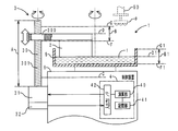
- FIG. 1 is a schematic diagram of a dip flux unit according to an embodiment of the present invention.
- FIG. 2 is a schematic diagram of the vicinity of the squeegee position adjusting unit of the dip flux unit.
- the dip flux unit 1 of the present embodiment includes a squeegee 2, a squeegee position adjustment unit 3, a control device 4, a transfer recess 5, and a unit body 6.
- the unit body 6 is attached to an electronic component mounting machine (not shown).
- the transfer recess 5 has a dish shape that opens upward.
- the transfer recess 5 is disposed on the upper side of the unit body 6.
- the transfer recess 5 can rotate around its own axis.
- the transfer recess 5 is formed with a film of flux f (shown highlighted in FIG. 1).
- the suction nozzle 90 of the electronic component mounting machine immerses an electronic component p such as BGA (Ball Grid Array) in the film of the flux f.
- the flux f is transferred to the electronic component p.
- a flux supply unit (not shown, such as a syringe) can add the flux f to the transfer recess 5.
- the squeegee position adjustment unit 3 is disposed in the unit main body 6.
- the squeegee position adjustment unit 3 includes a ball screw unit 30, a motor 31, and an encoder 32.
- the motor 31 is a servo motor.
- the encoder 32 is a multi-rotary rotary encoder.
- the encoder 32 generates an output pulse according to the rotation of the motor 31.
- the ball screw part 30 includes a driven part 300 and a driving part 301.
- the drive part 301 is a shaft part.
- the drive unit 301 extends in the vertical direction.
- the driven part 300 is a nut part.
- the driven unit 300 is screwed into the driving unit 301 via a large number of balls (not shown).
- the drive unit 301 is connected to the rotation shaft of the motor 31.
- a squeegee 2 described later is attached to the driven unit 300.
- the drive unit 301 rotates around its own axis.
- the driven unit 300 can move within the movable range A in the vertical direction (the extending direction of the driving unit 301).
- the squeegee 2 is disposed above the transfer recess 5.
- the squeegee 2 can be separated from the flux f film from above.
- the film of the flux f can be expanded.
- the film thickness of the flux f can be adjusted by adjusting the position (altitude) of the squeegee 2, in other words, the position (altitude) of the driven unit 300.
- the control device 4 is disposed in the unit body 6.
- the control device 4 includes a calculation unit 40, a storage unit 41, and an input / output interface 42.
- the calculation unit 40 is a CPU (Central Processing Unit).
- the storage unit 41 includes a ROM (Read Only Memory) and a RAM (Random Access Memory).
- the control device 4 is electrically connected to the motor 31 and the encoder 32.
- the upper limit position G1 of the squeegee 2 is the highest liquid level of the flux f in the transfer recess 5. For this reason, the upper limit position G of the driven portion 300 corresponds to the highest liquid level of the flux f in the transfer recess 5.
- the liquid level of the flux f is monitored by a liquid level sensor (not shown).
- the lower limit position F ⁇ b> 1 of the squeegee 2 is the bottom elevation of the transfer recess 5. For this reason, the lower limit position F of the driven portion 300 corresponds to the height of the bottom surface of the transfer recess 5.
- the correction position D1 of the squeegee 2 is set to approximately the center in the vertical direction between the lower limit position F1 and the upper limit position G1, that is, approximately in the vertical direction of the use range B1.
- the correction position D of the driven unit 300 is set to approximately the center in the vertical direction between the lower limit position F and the upper limit position G, that is, approximately in the vertical direction of the use range B.
- FIG. 2 is a schematic view of the vicinity of the squeegee position adjusting unit of the dip flux unit of the present embodiment.
- Table 1 shows a numerical list in the squeegee position correction method of the present embodiment.
- surface is a reference value and does not limit the content of this invention at all.
- the squeegee position correction method of the present embodiment includes a reset process, a movement process, and a correction process.
- the driven unit 300 is arranged at the reference position C.
- the calculation unit 40 shown in FIG. 1 drives the motor 31 and arranges the driven unit 300 at the reference position C stored in the storage unit 41.
- the reference position C is set near the lower limit position of the movable range A.
- the reference position C is set to be spaced downward from the lower limit position F of the use range B.
- the reference position C is set to a position where interference with adjacent components (such as the motor 31) can be avoided.
- the calculation unit 40 resets the coordinates of the reference position C to 0.
- the count value of the output pulse of the encoder 32 at the reference position C is reset to zero.
- the driven unit 300 is moved upward from the reference position C to the correction position D, as indicated by the white arrow in FIG.
- the calculation unit 40 drives the motor 31 and moves the driven unit 300 upward from the reference position C by a set distance L0. That is, the driven unit 300 is arranged at the correction position D.
- the length of the set distance L0 is the reference position C (design value), the maximum liquid level (design value) of the flux f in the transfer recess 5, and the bottom height (design value) of the transfer recess 5. Based on the setting.
- a use range B is set.
- the calculation unit 40 shown in FIG. 1 calculates the moving distance from the reference position C to the correction position D based on the count value of the output pulse of the encoder 32. That is, the calculation unit 40 calculates the calculation distance L1.
- the ball screw part 30 has a positioning error (movement distance error of the driven part 300 in the vertical direction). For this reason, the calculated distance L1 and the set distance L0 do not match.
- the correction amount H is stored in the storage unit 41.
- the correction amount H is an eigenvalue of the dip flux unit 1. That is, the correction amount H is different for each of the plurality of dip flux units 1. For this reason, the correction amount H is stored in the ROM together with the serial number and the like.
- the calculation unit 40 sets the use range B.
- the storage unit 41 stores the vertical width of the use range B.
- the calculation unit 40 sets the use range B, that is, the lower limit position F and the upper limit position G so that the correction position D is arranged at the center in the vertical direction of the use range B.
- the storage unit 41 stores the following correction formula, where the calculated distance from the reference position C to an arbitrary position based on the count value of the output pulse of the encoder 32 is L2.
- L3 L2 + (L2 ⁇ H / L1) (Formula 1)
- the calculation unit 40 corrects the calculated distance L2 based on the correction formula (Formula 1).
- the use range B of the driven unit 300 includes the correction position D instead of the reference position C.
- the correction position D is set at the center in the vertical direction of the use range B. For this reason, the use range B of the driven part 300 can be set centering on the correction position D with high positioning accuracy. Therefore, the positioning accuracy of the driven unit 300, that is, the positioning accuracy of the squeegee 2 can be improved.
- control device 4 corrects an arbitrary position within the use range B based on the correction amount H using the correction formula (Formula 1). For this reason, not only the correction position D but also the positioning accuracy at an arbitrary position within the use range B can be improved.
- the squeegee position correction method is executed before the dip flux unit 1 is shipped. Since the correction amount H is stored in the ROM, it cannot be rewritten. Therefore, it is possible to suppress the correction amount H, which is an eigenvalue of the dip flux unit 1, from being rewritten after shipment.
- the set distance L0 is actually measured by the master jig 91.
- the master jig 91 is shared by the plurality of dip flux units 1. For this reason, in the some dip flux unit 1, it can suppress that the setting distance L0 varies.
- the nut portion of the ball screw portion 30 is the driven portion 300.
- the shaft portion of the ball screw portion 30 is used as the drive portion 301.
- the shaft portion may be the driven portion 300.
- the nut portion may be the drive portion 301.
- the rotation shaft of the motor 31 and the nut part (drive part) may be connected by a belt or a gear, and the nut part may be rotated. And you may move a shaft part (driven part) to an up-down direction with respect to a nut part (drive part).
- the extending direction of the shaft portion is not particularly limited. For example, it may be in the horizontal direction.
- a power transmission mechanism including a belt and a gear may be interposed between the motor 31 and the drive unit 301.
- the timing for setting the correction amount H is not particularly limited.
- the correction amount H may be set after the dip flux unit 1 is shipped. Further, the correction amount H may be stored in the RAM of the storage unit 41. In this way, the correction amount H can be rewritten after the dip flux unit 1 is shipped.
- the correction amount H itself may be stored in the ROM (cannot be rewritten), and the additional correction amount for the correction amount H may be separately stored in the RAM. Further, the correction amount H is stored in a control device other than the control device 4 of the dip flux unit 1 (for example, a host computer of a production line, a control device of an electronic component mounting machine, a portable terminal such as a smartphone, a personal computer, etc.). May be.
- the setting method of the usage range B is not particularly limited.
- the upper limit position G and the lower limit position F may be set at positions that are equidistant from each other on the upper and lower sides of the correction position D with the correction position D as a reference.
- the upper limit position G may be set corresponding to the upper end of the standing wall of the transfer recess 5.
- the lower limit position F may be set corresponding to the replenishment liquid level that is the liquid level at which the flux f is added to the transfer recess 5.
- the upper limit position G and the lower limit position F may be set according to the size of the electrodes (bumps, terminals, etc.) of the electronic component p.
- the coordinates of the correction position D in the use range B are not particularly limited.
- the lower limit position F may be set to the correction position D.
- the upper limit position G may be set to the correction position D.
- the calculation unit 40 may correct the lower limit position F and the upper limit position G using the correction formula (Formula 1). That is, by substituting the calculated distance L2 from the reference position C to the lower limit position F based on the count value of the output pulse of the encoder 32 into the correction formula (Equation 1), the correction distance L3 from the reference position C to the lower limit position F is obtained. It may be calculated. Similarly, a correction distance L3 from the reference position C to the upper limit position G is assigned by substituting the calculated distance L2 from the reference position C to the upper limit position G based on the count value of the output pulse of the encoder 32 into the correction formula (Equation 1). May be calculated.
Landscapes
- Engineering & Computer Science (AREA)
- General Engineering & Computer Science (AREA)
- Mechanical Engineering (AREA)
- Manufacturing & Machinery (AREA)
- Microelectronics & Electronic Packaging (AREA)
- Electric Connection Of Electric Components To Printed Circuits (AREA)
- Transmission Devices (AREA)
Abstract
スキージ(2)の位置決め精度を向上させることが可能なディップフラックスユニット(1)およびスキージ位置補正方法を提供する。ディップフラックスユニット(1)は、スキージ(2)とスキージ位置調整部(3)と制御装置(4)とを備える。スキージ位置調整部(3)は、従動部(300)と駆動部(301)とを有するボールねじ部(30)と、駆動部(301)を動かすモータ(31)と、モータ(31)の回転に応じて出力パルスを発生するエンコーダ(32)と、を有する。従動部(300)の可動範囲(A)には、使用範囲(B)に含まれない基準位置(C)と、使用範囲(B)に含まれる補正位置(D)と、が設定されている。制御装置(4)は、基準位置(C)から補正位置(D)までの設定距離(L0)と、出力パルスのカウント値に基づく基準位置(C)から補正位置(D)までの算出距離(L1)と、の差分(H)を基に、算出距離(L1)を補正する。
Description
本発明は、電子部品にフラックスを塗布するディップフラックスユニット、および当該ディップフラックスユニットのスキージ位置補正方法に関する。
特許文献1に示すように、電子部品実装機には、ディップフラックスユニットが配置されている。ディップフラックスユニットは、電子部品の電極(バンプ、端子など)にフラックスを塗布する際に用いられる。すなわち、ディップフラックスユニットの転写テーブルには、フラックスの膜が形成されている。当該フラックスの膜に電子部品を浸漬することにより、電子部品にフラックスが塗布される。フラックスの膜厚は、フラックスの膜をスキージで押し拡げることにより、調整可能である。具体的には、スキージの位置(高度)を高く設定すると、転写テーブル底面からスキージまでの距離が大きくなるため、フラックスの膜厚を大きくすることができる。反対に、スキージの位置を低く設定すると、転写テーブル底面からスキージまでの距離が小さくなるため、フラックスの膜厚を小さくすることができる。
ここで、スキージの位置の変更、つまりフラックスの膜厚の調整は、ボールねじにより行われる。ボールねじのシャフトは、モータにより駆動される。ボールねじのナットには、スキージが取り付けられている。モータは、制御装置からの指令に基づき作動する。エンコーダは、モータの回転に応じて出力パルスを発生する。
ディップフラックスユニットの出荷前には、ボールねじのリセット作業が行われている。具体的には、シャフトの軸方向に延在するナットの可動範囲のうち、下限位置付近の位置を、基準位置に設定している。そして、当該基準位置の座標を、0に設定している。並びに、当該基準位置におけるエンコーダの出力パルスのカウント値を、0に設定している。
しかしながら、ボールねじは、位置決め誤差を有している。このため、スキージの位置を変更する際、制御装置の指令距離と、スキージの移動距離と、の間に誤差が発生してしまう。したがって、スキージの位置決め精度が低下してしまう。そこで、本発明は、スキージの位置決め精度を向上させることが可能なディップフラックスユニットおよびスキージ位置補正方法を提供することを目的とする。
(1)上記課題を解決するため、本発明のディップフラックスユニットは、スキージと、ナット部とシャフト部とを有し、該ナット部および該シャフト部のうち、一方は駆動部であり、他方は該駆動部に対して所定の可動範囲において従動すると共に該スキージが取り付けられる従動部であるボールねじ部と、該駆動部を動かすモータと、該モータの回転に応じて出力パルスを発生するエンコーダと、を有するスキージ位置調整部と、該モータに駆動指示を出す制御装置と、を備えるディップフラックスユニットであって、前記可動範囲には、前記スキージの位置調整に用いられる前記従動部の使用範囲に含まれない基準位置と、該使用範囲に含まれる補正位置と、が設定され、前記制御装置は、該基準位置から該補正位置までの設定距離と、前記出力パルスのカウント値に基づく該基準位置から該補正位置までの算出距離と、の差分を基に、該算出距離を補正することを特徴とする。
ここで、「設定距離」とは、例えばマスター治具や測定工具やスケールなどによる実測距離、制御装置からの指令距離など、出力パルスのカウント値に基づかない、基準位置から補正位置までの距離をいう。
ボールねじ部は、位置決め誤差(シャフト部の軸方向における、従動部(ナット部またはシャフト部)の移動距離誤差)を有している。駆動部(シャフト部またはナット部)が1回転するたびに、誤差は累積される。このため、駆動部の回転量が多いほど、言い換えると基準位置からの距離が大きいほど、位置決め誤差は大きくなる。このため、基準位置を含むように従動部の使用範囲を設定すると、位置決め誤差を小さくすることができる。
しかしながら、例えばディップフラックスユニットの構造など種々の事情により、従動部の使用範囲に基準位置を含めることができない場合がある。この場合、基準位置から使用範囲までの距離が大きくなりやすい。このため、位置決め誤差が大きくなりやすい。
この点、本発明のディップフラックスユニットによると、従動部の使用範囲に、基準位置の代わりに、補正位置が含まれている。制御装置は、基準位置から補正位置までの設定距離と、基準位置から補正位置までの算出距離と、の差分を基に、算出距離を補正している。すなわち、基準位置から補正位置までの位置決め誤差を考慮して、算出距離、つまり補正位置の座標を補正している。このため、使用範囲における従動部の位置決め精度、つまりスキージの位置決め精度を、向上させることができる。
(2)上記(1)の構成において、さらに、前記スキージにより押し拡げられるフラックスが貯留された転写凹部を備え、前記使用範囲は、該転写凹部の底面高度に対応する下限位置と、該転写凹部における該フラックスの最高液位に対応する上限位置と、の間に設定され、前記補正位置は、該使用範囲の上下方向中央に設定される構成とする方がよい。
本構成によると、位置決め精度の高い補正位置を中心に、従動部の使用範囲を設定することができる。このため、さらに、従動部の位置決め精度、つまりスキージの位置決め精度を、向上させることができる。
(3)上記(1)または(2)の構成において、前記制御装置は、前記差分を基に前記使用範囲内の任意の位置を補正する構成とする方がよい。本構成によると、差分を基に、補正位置のみならず、使用範囲内の任意の位置における位置決め精度を向上させることができる。
(3-1)上記(3)の構成において、前記出力パルスのカウント値に基づく前記基準位置から前記補正位置までの算出距離をL1、該カウント値に基づく該基準位置から前記任意の位置までの算出距離をL2、前記差分をH、該基準位置から前記任意の位置までの補正距離をL3として、L3は以下の補正式から求められる構成とする方がよい。
L3=L2+(L2×H/L1) ・・・(式1)
L3=L2+(L2×H/L1) ・・・(式1)
本構成によると、差分Hを基に、基準位置から使用範囲内の任意の位置までの補正距離L3を、算出することができる。すなわち、任意の位置における位置決め精度を向上させることができる。
(4)上記課題を解決するため、本発明のスキージ位置補正方法は、スキージと、ナット部とシャフト部とを有し、該ナット部および該シャフト部のうち、一方は駆動部であり、他方は該駆動部に対して所定の可動範囲において従動すると共に該スキージが取り付けられる従動部であるボールねじ部と、該駆動部を動かすモータと、該モータの回転に応じて出力パルスを発生するエンコーダと、を有するスキージ位置調整部と、を備えるディップフラックスユニットのスキージ位置補正方法であって、前記可動範囲には、前記スキージの位置調整に用いられる前記従動部の使用範囲に含まれない基準位置と、該使用範囲に含まれる補正位置と、が設定され、該従動部を、該基準位置に配置し、前記出力パルスのカウント値をリセットするリセット工程と、該従動部を、該基準位置から該補正位置まで、設定距離だけ移動させる移動工程と、該設定距離と、該出力パルスの該カウント値に基づく該基準位置から該補正位置までの算出距離と、の差分を基に該算出距離を補正する補正工程と、を有することを特徴とする。上記(1)に記載したように、本発明のスキージ位置補正方法によると、使用範囲における従動部の位置決め精度、つまりスキージの位置決め精度を、向上させることができる。
本発明によると、スキージの位置決め精度を向上させることが可能なディップフラックスユニットおよびスキージ位置補正方法を提供することができる。
以下、本発明のディップフラックスユニットおよびスキージ位置補正方法の実施の形態について説明する。
<ディップフラックスユニットの構成>
まず、本実施形態のディップフラックスユニットの構成について説明する。図1に、本実施形態のディップフラックスユニットの模式図を示す。図1に示すように、本実施形態のディップフラックスユニット1は、スキージ2と、スキージ位置調整部3と、制御装置4と、転写凹部5と、ユニット本体6と、を備えている。
まず、本実施形態のディップフラックスユニットの構成について説明する。図1に、本実施形態のディップフラックスユニットの模式図を示す。図1に示すように、本実施形態のディップフラックスユニット1は、スキージ2と、スキージ位置調整部3と、制御装置4と、転写凹部5と、ユニット本体6と、を備えている。
ユニット本体6は、電子部品実装機(図略)に取り付けられている。転写凹部5は、上側に開口する皿状を呈している。転写凹部5は、ユニット本体6の上側に配置されている。転写凹部5は、自身の軸周りに回転可能である。転写凹部5には、フラックスfの膜(図1においては強調して示す)が形成されている。電子部品実装機の吸着ノズル90は、フラックスfの膜に、BGA(Ball Grid Array)などの電子部品pを、浸漬する。電子部品pには、フラックスfが転写される。フラックス供給部(図略、例えばシリンジなど)は、転写凹部5に、フラックスfを注ぎ足すことができる。
スキージ位置調整部3は、ユニット本体6に配置されている。スキージ位置調整部3は、ボールねじ部30と、モータ31と、エンコーダ32と、を備えている。モータ31は、サーボモータである。エンコーダ32は、多回転ロータリーエンコーダである。エンコーダ32は、モータ31の回転に応じて、出力パルスを発生する。ボールねじ部30は、従動部300と駆動部301とを備えている。駆動部301は、シャフト部である。駆動部301は、上下方向に延在している。従動部300は、ナット部である。従動部300は、多数のボール(図略)を介して、駆動部301に螺合している。駆動部301は、モータ31の回転軸に連結されている。従動部300には、後述するスキージ2が取り付けられている。モータ31を駆動すると、駆動部301は、自身の軸周りに回転する。従動部300は、上下方向(駆動部301の延在方向)に、可動範囲A内を移動可能である。
スキージ2は、転写凹部5の上側に配置されている。スキージ2は、フラックスfの膜に、上側から離接可能である。スキージ2をフラックスfの膜に当接させた状態で転写凹部5を回転させることにより、フラックスfの膜を押し拡げることができる。また、スキージ2の位置(高度)、言い換えると従動部300の位置(高度)を調整することにより、フラックスfの膜厚を調整することができる。
制御装置4は、ユニット本体6に配置されている。制御装置4は、演算部40と、記憶部41と、入出力インターフェイス42と、を備えている。演算部40は、CPU(Central Processing Unit)である。記憶部41は、ROM(Read Only Memory)と、RAM(Random Access Memory)と、を備えている。制御装置4は、モータ31、エンコーダ32に、電気的に接続されている。
<従動部の使用範囲とスキージの使用範囲との対応>
次に、従動部300の使用範囲Bと、スキージ2の使用範囲B1と、の対応について説明する。前述したように、スキージ2は、従動部300に取り付けられている。このため、従動部300の使用範囲Bと、スキージ2の使用範囲B1と、は対応している。具体的には、従動部300の補正位置Dと、スキージ2の補正位置D1と、は対応している。また、従動部300の下限位置Fと、スキージ2の下限位置F1と、は対応している。また、従動部300の上限位置Gと、スキージ2の上限位置G1と、は対応している。
次に、従動部300の使用範囲Bと、スキージ2の使用範囲B1と、の対応について説明する。前述したように、スキージ2は、従動部300に取り付けられている。このため、従動部300の使用範囲Bと、スキージ2の使用範囲B1と、は対応している。具体的には、従動部300の補正位置Dと、スキージ2の補正位置D1と、は対応している。また、従動部300の下限位置Fと、スキージ2の下限位置F1と、は対応している。また、従動部300の上限位置Gと、スキージ2の上限位置G1と、は対応している。
スキージ2の上限位置G1は、転写凹部5におけるフラックスfの最高液位である。このため、従動部300の上限位置Gは、転写凹部5におけるフラックスfの最高液位に対応している。なお、フラックスfの液位は、液面センサ(図略)により監視されている。また、スキージ2の下限位置F1は、転写凹部5の底面高度である。このため、従動部300の下限位置Fは、転写凹部5の底面高度に対応している。
スキージ2の補正位置D1は、下限位置F1と上限位置G1との上下方向略中央、つまり使用範囲B1の上下方向略中央に設定されている。同様に、従動部300の補正位置Dは、下限位置Fと上限位置Gとの上下方向略中央、つまり使用範囲Bの上下方向略中央に設定されている。
<スキージ位置補正方法>
次に、本実施形態のスキージ位置補正方法について説明する。スキージ位置補正方法は、ディップフラックスユニット1の出荷前に実行される。図2に、本実施形態のディップフラックスユニットのスキージ位置調整部付近の模式図を示す。表1に、本実施形態のスキージ位置補正方法における数値一覧表を示す。なお、表中の数値は参考値であり、本発明の内容を何等限定するものではない。本実施形態のスキージ位置補正方法は、リセット工程と、移動工程と、補正工程と、を有している。

次に、本実施形態のスキージ位置補正方法について説明する。スキージ位置補正方法は、ディップフラックスユニット1の出荷前に実行される。図2に、本実施形態のディップフラックスユニットのスキージ位置調整部付近の模式図を示す。表1に、本実施形態のスキージ位置補正方法における数値一覧表を示す。なお、表中の数値は参考値であり、本発明の内容を何等限定するものではない。本実施形態のスキージ位置補正方法は、リセット工程と、移動工程と、補正工程と、を有している。
リセット工程においては、従動部300を基準位置Cに配置する。まず、図1に示す演算部40は、モータ31を駆動し、記憶部41に保存された基準位置Cに、従動部300を配置する。なお、基準位置Cは、可動範囲Aの下限位置付近に設定されている。基準位置Cは、使用範囲Bの下限位置Fに対して、下側に離間して設定されている。基準位置Cは、隣接する部品(モータ31など)との干渉を回避可能な位置に、設定されている。次に、演算部40は、基準位置Cの座標を、0にリセットする。並びに、基準位置Cにおけるエンコーダ32の出力パルスのカウント値を、0にリセットする。
移動工程においては、図2に白抜き矢印で示すように、従動部300を、基準位置Cから補正位置Dまで、上側に移動させる。図1に示す記憶部41には、マスター治具91により実測された設定距離L0(=500)が、保存されている。演算部40は、モータ31を駆動し、従動部300を、基準位置Cから設定距離L0だけ上側に移動させる。すなわち、補正位置Dに、従動部300を配置する。
なお、マスター治具91において、設定距離L0の長さは、基準位置C(設計値)、転写凹部5におけるフラックスfの最高液位(設計値)、転写凹部5の底面高度(設計値)を基に、設定されている。
補正工程においては、算出距離L1(=490)を補正する。また、使用範囲Bを設定する。まず、図1に示す演算部40は、エンコーダ32の出力パルスのカウント値に基づいて、基準位置Cから補正位置Dまでの移動距離を算出する。つまり、演算部40は、算出距離L1を算出する。ボールねじ部30は、位置決め誤差(上下方向における従動部300の移動距離誤差)を有している。このため、算出距離L1と設定距離L0とは一致しない。
次に、演算部40は、設定距離L0(=500)と、算出距離L1(=490)と、の差分である補正量H(=10)を算出する。補正量Hは、記憶部41に保存される。なお、補正量Hは、ディップフラックスユニット1の固有値である。すなわち、補正量Hは、複数のディップフラックスユニット1において、一台ごとに異なっている。このため、補正量Hは、シリアルナンバーなどと共に、ROMに保存される。
続いて、演算部40は、算出距離L1を補正する。具体的には、演算部40は、算出距離L1(=490)に補正量H(=10)を加算することにより、補正距離L3(=500)を算出する。
それから、演算部40は、使用範囲Bを設定する。記憶部41には、使用範囲Bの上下方向幅が記憶されている。演算部40は、使用範囲Bの上下方向中央に補正位置Dが配置されるように、使用範囲Bつまり下限位置Fおよび上限位置Gを設定する。
また、記憶部41には、エンコーダ32の出力パルスのカウント値に基づく基準位置Cから任意の位置までの算出距離をL2として、以下の補正式が保存されている。
L3=L2+(L2×H/L1) ・・・(式1)
L3=L2+(L2×H/L1) ・・・(式1)
ディップフラックスユニット1使用時において、演算部40は、補正式(式1)を基に、算出距離L2を補正する。
<作用効果>
次に、本実施形態のディップフラックスユニットおよびスキージ位置補正方法の作用効果について説明する。図1、図2に示すように、本実施形態のディップフラックスユニット1によると、従動部300の使用範囲Bに、基準位置Cではなく、補正位置Dが含まれている。表1に示すように、制御装置4は、基準位置Cから補正位置Dまでの設定距離L0(=500)と、基準位置Cから補正位置Dまでの算出距離L1(=490)と、の差分である補正量H(=10)を基に、算出距離L1を補正している。すなわち、基準位置Cから補正位置Dまでの位置決め誤差を考慮して、算出距離L1、つまり補正位置Dの座標を補正している。このため、使用範囲Bにおける従動部300の位置決め精度、つまりスキージ2の位置決め精度を、向上させることができる。
次に、本実施形態のディップフラックスユニットおよびスキージ位置補正方法の作用効果について説明する。図1、図2に示すように、本実施形態のディップフラックスユニット1によると、従動部300の使用範囲Bに、基準位置Cではなく、補正位置Dが含まれている。表1に示すように、制御装置4は、基準位置Cから補正位置Dまでの設定距離L0(=500)と、基準位置Cから補正位置Dまでの算出距離L1(=490)と、の差分である補正量H(=10)を基に、算出距離L1を補正している。すなわち、基準位置Cから補正位置Dまでの位置決め誤差を考慮して、算出距離L1、つまり補正位置Dの座標を補正している。このため、使用範囲Bにおける従動部300の位置決め精度、つまりスキージ2の位置決め精度を、向上させることができる。
また、補正位置Dは、使用範囲Bの上下方向中央に設定されている。このため、位置決め精度の高い補正位置Dを中心に、従動部300の使用範囲Bを設定することができる。したがって、従動部300の位置決め精度、つまりスキージ2の位置決め精度を、向上させることができる。
また、制御装置4は、補正式(式1)を用いて、補正量Hを基に使用範囲B内の任意の位置を補正している。このため、補正位置Dのみならず、使用範囲B内の任意の位置における位置決め精度を向上させることができる。
また、スキージ位置補正方法は、ディップフラックスユニット1の出荷前に実行される。補正量Hは、ROMに保存されているため、書き換え不能である。したがって、ディップフラックスユニット1の固有値である補正量Hが、出荷後に書き換えられるのを、抑制することができる。
また、図2に示すように、設定距離L0は、マスター治具91により実測される。マスター治具91は、複数のディップフラックスユニット1において共用されている。このため、複数のディップフラックスユニット1において、設定距離L0がばらつくのを、抑制することができる。
<その他>
以上、本発明のディップフラックスユニットおよびスキージ位置補正方法の実施の形態について説明した。しかしながら、実施の形態は上記形態に特に限定されるものではない。当業者が行いうる種々の変形的形態、改良的形態で実施することも可能である。
以上、本発明のディップフラックスユニットおよびスキージ位置補正方法の実施の形態について説明した。しかしながら、実施の形態は上記形態に特に限定されるものではない。当業者が行いうる種々の変形的形態、改良的形態で実施することも可能である。
上記実施形態においては、ボールねじ部30のナット部を従動部300とした。並びに、ボールねじ部30のシャフト部を駆動部301とした。しかしながら、シャフト部を従動部300としてもよい。並びに、ナット部を駆動部301としてもよい。この場合、例えば、モータ31の回転軸とナット部(駆動部)とをベルトやギアなどで連結し、ナット部を回転させてもよい。そして、ナット部(駆動部)に対して、シャフト部(従動部)を上下方向に移動させてもよい。また、シャフト部の延在方向は特に限定しない。例えば、水平方向であってもよい。また、モータ31と駆動部301との間に、ベルトやギアを備える動力伝達機構を、介装してもよい。
補正量Hの設定のタイミングは、特に限定しない。補正量Hの設定は、ディップフラックスユニット1の出荷後に行ってもよい。また、記憶部41のRAMに補正量Hを保存してもよい。こうすると、ディップフラックスユニット1の出荷後に、補正量Hを書き換えることができる。また、補正量H自体はROMに保存し(書き換え不能とし)、当該補正量Hに対する追加補正量を、別途、RAMに保存してもよい。また、補正量Hを、ディップフラックスユニット1の制御装置4以外の制御装置(例えば、生産ラインのホストコンピュータ、電子部品実装機の制御装置、スマートフォンなどの携帯端末、パーソナルコンピュータなど)に、保存してもよい。
使用範囲Bの設定方法は特に限定しない。例えば、補正位置Dを基準として、補正位置Dの上下両側に等距離だけ離間した位置に、上限位置G、下限位置Fを設定してもよい。また、上限位置Gは、転写凹部5の立壁の上端に対応して、設定してもよい。また、下限位置Fは、転写凹部5にフラックスfを注ぎ足す液位である補給液位に対応して、設定してもよい。また、電子部品pの電極(バンプ、端子など)の大きさに応じて、上限位置G、下限位置Fを設定してもよい。また、使用範囲Bにおける補正位置Dの座標は、特に限定しない。例えば、下限位置Fを補正位置Dに設定してもよい。また、上限位置Gを補正位置Dに設定してもよい。
また、演算部40は、補正式(式1)を用いて、下限位置F、上限位置Gを補正してもよい。すなわち、エンコーダ32の出力パルスのカウント値に基づく基準位置Cから下限位置Fまでの算出距離L2を補正式(式1)に代入することにより、基準位置Cから下限位置Fまでの補正距離L3を算出してもよい。同様に、エンコーダ32の出力パルスのカウント値に基づく基準位置Cから上限位置Gまでの算出距離L2を補正式(式1)に代入することにより、基準位置Cから上限位置Gまでの補正距離L3を算出してもよい。
1:ディップフラックスユニット、2:スキージ、3:スキージ位置調整部、30:ボールねじ部、300:従動部(ナット部)、301:駆動部(シャフト部)、31:モータ、32:エンコーダ、4:制御装置、40:演算部、41:記憶部、42:入出力インターフェイス、5:転写凹部、6:ユニット本体、90:吸着ノズル、91:マスター治具、A:可動範囲、B:使用範囲、C:基準位置、D:補正位置、F:下限位置、G:上限位置、B1:使用範囲、D1:補正位置、F1:下限位置、G1:上限位置、H:補正量(差分)、L0:設定距離、L1:算出距離、L3:補正距離、f:フラックス、p:電子部品。
Claims (4)
- スキージと、
ナット部とシャフト部とを有し、該ナット部および該シャフト部のうち、一方は駆動部であり、他方は該駆動部に対して所定の可動範囲において従動すると共に該スキージが取り付けられる従動部であるボールねじ部と、該駆動部を動かすモータと、該モータの回転に応じて出力パルスを発生するエンコーダと、を有するスキージ位置調整部と、
該モータに駆動指示を出す制御装置と、
を備えるディップフラックスユニットであって、
前記可動範囲には、前記スキージの位置調整に用いられる前記従動部の使用範囲に含まれない基準位置と、該使用範囲に含まれる補正位置と、が設定され、
前記制御装置は、該基準位置から該補正位置までの設定距離と、前記出力パルスのカウント値に基づく該基準位置から該補正位置までの算出距離と、の差分を基に、該算出距離を補正することを特徴とするディップフラックスユニット。 - さらに、前記スキージにより押し拡げられるフラックスが貯留された転写凹部を備え、
前記使用範囲は、該転写凹部の底面高度に対応する下限位置と、該転写凹部における該フラックスの最高液位に対応する上限位置と、の間に設定され、
前記補正位置は、該使用範囲の上下方向中央に設定される請求項1に記載のディップフラックスユニット。 - 前記制御装置は、前記差分を基に前記使用範囲内の任意の位置を補正する請求項1または請求項2に記載のディップフラックスユニット。
- スキージと、
ナット部とシャフト部とを有し、該ナット部および該シャフト部のうち、一方は駆動部であり、他方は該駆動部に対して所定の可動範囲において従動すると共に該スキージが取り付けられる従動部であるボールねじ部と、該駆動部を動かすモータと、該モータの回転に応じて出力パルスを発生するエンコーダと、を有するスキージ位置調整部と、
を備えるディップフラックスユニットのスキージ位置補正方法であって、
前記可動範囲には、前記スキージの位置調整に用いられる前記従動部の使用範囲に含まれない基準位置と、該使用範囲に含まれる補正位置と、が設定され、
該従動部を、該基準位置に配置し、前記出力パルスのカウント値をリセットするリセット工程と、
該従動部を、該基準位置から該補正位置まで、設定距離だけ移動させる移動工程と、
該設定距離と、該出力パルスの該カウント値に基づく該基準位置から該補正位置までの算出距離と、の差分を基に該算出距離を補正する補正工程と、
を有するスキージ位置補正方法。
Priority Applications (2)
| Application Number | Priority Date | Filing Date | Title |
|---|---|---|---|
| JP2016537702A JP6467425B2 (ja) | 2014-08-01 | 2014-08-01 | ディップフラックスユニットおよびスキージ位置補正方法 |
| PCT/JP2014/070339 WO2016017027A1 (ja) | 2014-08-01 | 2014-08-01 | ディップフラックスユニットおよびスキージ位置補正方法 |
Applications Claiming Priority (1)
| Application Number | Priority Date | Filing Date | Title |
|---|---|---|---|
| PCT/JP2014/070339 WO2016017027A1 (ja) | 2014-08-01 | 2014-08-01 | ディップフラックスユニットおよびスキージ位置補正方法 |
Publications (1)
| Publication Number | Publication Date |
|---|---|
| WO2016017027A1 true WO2016017027A1 (ja) | 2016-02-04 |
Family
ID=55216962
Family Applications (1)
| Application Number | Title | Priority Date | Filing Date |
|---|---|---|---|
| PCT/JP2014/070339 Ceased WO2016017027A1 (ja) | 2014-08-01 | 2014-08-01 | ディップフラックスユニットおよびスキージ位置補正方法 |
Country Status (2)
| Country | Link |
|---|---|
| JP (1) | JP6467425B2 (ja) |
| WO (1) | WO2016017027A1 (ja) |
Cited By (1)
| Publication number | Priority date | Publication date | Assignee | Title |
|---|---|---|---|---|
| KR20190068787A (ko) * | 2017-12-11 | 2019-06-19 | 두산공작기계 주식회사 | 공작기계의 윤활유 공급 제어장치 및 제어방법 |
Citations (6)
| Publication number | Priority date | Publication date | Assignee | Title |
|---|---|---|---|---|
| JPH0844431A (ja) * | 1994-08-01 | 1996-02-16 | Bridgestone Corp | 位置決め制御方法 |
| JPH0878882A (ja) * | 1994-09-02 | 1996-03-22 | Fuji Mach Mfg Co Ltd | 対回路基板トランスファ作業装置 |
| JPH08153960A (ja) * | 1994-11-28 | 1996-06-11 | Matsushita Electric Ind Co Ltd | 半田ボールの搭載装置および搭載方法 |
| JPH11138746A (ja) * | 1997-11-10 | 1999-05-25 | Matsushita Electric Ind Co Ltd | 印刷方法及び印刷装置 |
| JP2007047657A (ja) * | 2005-08-12 | 2007-02-22 | Mitsutoyo Corp | スリット幅調整装置およびこれを備えた顕微鏡レーザリペア装置 |
| JP2011211219A (ja) * | 2011-06-06 | 2011-10-20 | Sony Corp | 実装装置、塗布方法及び実装基板の製造方法 |
-
2014
- 2014-08-01 JP JP2016537702A patent/JP6467425B2/ja active Active
- 2014-08-01 WO PCT/JP2014/070339 patent/WO2016017027A1/ja not_active Ceased
Patent Citations (6)
| Publication number | Priority date | Publication date | Assignee | Title |
|---|---|---|---|---|
| JPH0844431A (ja) * | 1994-08-01 | 1996-02-16 | Bridgestone Corp | 位置決め制御方法 |
| JPH0878882A (ja) * | 1994-09-02 | 1996-03-22 | Fuji Mach Mfg Co Ltd | 対回路基板トランスファ作業装置 |
| JPH08153960A (ja) * | 1994-11-28 | 1996-06-11 | Matsushita Electric Ind Co Ltd | 半田ボールの搭載装置および搭載方法 |
| JPH11138746A (ja) * | 1997-11-10 | 1999-05-25 | Matsushita Electric Ind Co Ltd | 印刷方法及び印刷装置 |
| JP2007047657A (ja) * | 2005-08-12 | 2007-02-22 | Mitsutoyo Corp | スリット幅調整装置およびこれを備えた顕微鏡レーザリペア装置 |
| JP2011211219A (ja) * | 2011-06-06 | 2011-10-20 | Sony Corp | 実装装置、塗布方法及び実装基板の製造方法 |
Cited By (3)
| Publication number | Priority date | Publication date | Assignee | Title |
|---|---|---|---|---|
| KR20190068787A (ko) * | 2017-12-11 | 2019-06-19 | 두산공작기계 주식회사 | 공작기계의 윤활유 공급 제어장치 및 제어방법 |
| WO2019117504A1 (ko) * | 2017-12-11 | 2019-06-20 | 두산공작기계 주식회사 | 공작기계의 윤활유 공급 제어장치 및 제어방법 |
| KR102498440B1 (ko) | 2017-12-11 | 2023-02-10 | 주식회사 디엔솔루션즈 | 공작기계의 윤활유 공급 제어장치 및 제어방법 |
Also Published As
| Publication number | Publication date |
|---|---|
| JPWO2016017027A1 (ja) | 2017-05-18 |
| JP6467425B2 (ja) | 2019-02-13 |
Similar Documents
| Publication | Publication Date | Title |
|---|---|---|
| CN108274754B (zh) | 立体打印装置以及打印校正方法 | |
| US20180224681A1 (en) | Cell forming device and alignment method | |
| JP6640214B2 (ja) | 部品実装機の制御装置および制御方法 | |
| CN204220843U (zh) | 用于弯折二极管引脚的弯脚机 | |
| CN104827779B (zh) | 万向打标机 | |
| CN110091340B (zh) | 一种晶圆取放机械手 | |
| CN105215990A (zh) | 机械手臂系统及其平行度校正方法 | |
| CN103391708A (zh) | 元件或基板的作业装置和元件安装装置 | |
| JP2013239517A (ja) | 部品または基板の作業装置および部品実装装置 | |
| CN104942802A (zh) | 工业用机器人 | |
| CN204641090U (zh) | 万向打标机 | |
| JP6467425B2 (ja) | ディップフラックスユニットおよびスキージ位置補正方法 | |
| CN105698726A (zh) | 测量及校准运动平台定位精度的方法与装置 | |
| JP2013115142A (ja) | 表面実装装置およびヘッド駆動制御方法 | |
| US9778647B2 (en) | Working machine and positional deviation data acquisition method | |
| JP6161598B2 (ja) | パラレルリンク式部品実装装置 | |
| CN104816477A (zh) | 一种3d打印机底板调平装置 | |
| EP3603887A1 (en) | Method and apparatus for flexible detection and positioning | |
| CN212625498U (zh) | 一种用于自动校正平台水平度的装置 | |
| CN112936315A (zh) | 一种基于成像方式的机械臂校准方法及装置 | |
| KR20210024968A (ko) | 적재 장치의 제어 방법, 적재 장치 및 검사 장치 | |
| CN106772888A (zh) | 五自由度自适应位姿调整平台 | |
| JP6429789B2 (ja) | 回路基材支持システム | |
| CN208011213U (zh) | 一种高精度重载云台摄像机 | |
| JP6457295B2 (ja) | 部品判定装置 |
Legal Events
| Date | Code | Title | Description |
|---|---|---|---|
| 121 | Ep: the epo has been informed by wipo that ep was designated in this application |
Ref document number: 14899071 Country of ref document: EP Kind code of ref document: A1 |
|
| ENP | Entry into the national phase |
Ref document number: 2016537702 Country of ref document: JP Kind code of ref document: A |
|
| NENP | Non-entry into the national phase |
Ref country code: DE |
|
| 122 | Ep: pct application non-entry in european phase |
Ref document number: 14899071 Country of ref document: EP Kind code of ref document: A1 |