WO2016013583A1 - 空気入りタイヤ - Google Patents
空気入りタイヤ Download PDFInfo
- Publication number
- WO2016013583A1 WO2016013583A1 PCT/JP2015/070851 JP2015070851W WO2016013583A1 WO 2016013583 A1 WO2016013583 A1 WO 2016013583A1 JP 2015070851 W JP2015070851 W JP 2015070851W WO 2016013583 A1 WO2016013583 A1 WO 2016013583A1
- Authority
- WO
- WIPO (PCT)
- Prior art keywords
- fastener
- fiber
- tire
- pneumatic tire
- reinforcing material
- Prior art date
- Legal status (The legal status is an assumption and is not a legal conclusion. Google has not performed a legal analysis and makes no representation as to the accuracy of the status listed.)
- Ceased
Links
Images


Classifications
-
- B—PERFORMING OPERATIONS; TRANSPORTING
- B60—VEHICLES IN GENERAL
- B60C—VEHICLE TYRES; TYRE INFLATION; TYRE CHANGING; CONNECTING VALVES TO INFLATABLE ELASTIC BODIES IN GENERAL; DEVICES OR ARRANGEMENTS RELATED TO TYRES
- B60C19/00—Tyre parts or constructions not otherwise provided for
- B60C19/001—Tyres requiring an asymmetric or a special mounting
-
- B—PERFORMING OPERATIONS; TRANSPORTING
- B60—VEHICLES IN GENERAL
- B60C—VEHICLE TYRES; TYRE INFLATION; TYRE CHANGING; CONNECTING VALVES TO INFLATABLE ELASTIC BODIES IN GENERAL; DEVICES OR ARRANGEMENTS RELATED TO TYRES
- B60C23/00—Devices for measuring, signalling, controlling, or distributing tyre pressure or temperature, specially adapted for mounting on vehicles; Arrangement of tyre inflating devices on vehicles, e.g. of pumps or of tanks; Tyre cooling arrangements
- B60C23/02—Signalling devices actuated by tyre pressure
- B60C23/04—Signalling devices actuated by tyre pressure mounted on the wheel or tyre
- B60C23/0491—Constructional details of means for attaching the control device
- B60C23/0493—Constructional details of means for attaching the control device for attachment on the tyre
-
- B—PERFORMING OPERATIONS; TRANSPORTING
- B29—WORKING OF PLASTICS; WORKING OF SUBSTANCES IN A PLASTIC STATE IN GENERAL
- B29D—PRODUCING PARTICULAR ARTICLES FROM PLASTICS OR FROM SUBSTANCES IN A PLASTIC STATE
- B29D30/00—Producing pneumatic or solid tyres or parts thereof
- B29D30/0061—Accessories, details or auxiliary operations not otherwise provided for
-
- B—PERFORMING OPERATIONS; TRANSPORTING
- B29—WORKING OF PLASTICS; WORKING OF SUBSTANCES IN A PLASTIC STATE IN GENERAL
- B29D—PRODUCING PARTICULAR ARTICLES FROM PLASTICS OR FROM SUBSTANCES IN A PLASTIC STATE
- B29D30/00—Producing pneumatic or solid tyres or parts thereof
- B29D30/06—Pneumatic tyres or parts thereof (e.g. produced by casting, moulding, compression moulding, injection moulding, centrifugal casting)
- B29D30/0681—Parts of pneumatic tyres; accessories, auxiliary operations
-
- B—PERFORMING OPERATIONS; TRANSPORTING
- B29—WORKING OF PLASTICS; WORKING OF SUBSTANCES IN A PLASTIC STATE IN GENERAL
- B29D—PRODUCING PARTICULAR ARTICLES FROM PLASTICS OR FROM SUBSTANCES IN A PLASTIC STATE
- B29D30/00—Producing pneumatic or solid tyres or parts thereof
- B29D30/0061—Accessories, details or auxiliary operations not otherwise provided for
- B29D2030/0072—Attaching fasteners to tyres, e.g. patches, in order to connect devices to tyres
Definitions
- the present invention relates to a pneumatic tire, and more particularly, to a pneumatic tire capable of firmly attaching an object to the inner surface of the pneumatic tire.
- a tire tag high frequency identification tag
- a mounting method has been proposed (Patent Documents 1 and 2).
- Patent Documents 3 and 4 a pneumatic tire having one of a pair of mechanical fasteners that can be separated into two on the tire inner surface.
- Patent Documents 3 and 4 a pneumatic tire having one of a pair of mechanical fasteners that can be separated into two on the tire inner surface.
- the present inventors embed the fasteners one by one in a tread rubber and perform vulcanization, and among a pair of mechanical fasteners that can be separated into two,
- One mechanical fastener provided on the inner surface of the tire is a mechanical fastener composed of at least two fastener constituent members, and the two or more fastener constituent members are covered with a rubber layer or rubber. It has been proposed to fix with a reinforcing material in between (Patent Document 3).
- Patent Document 4 it has been proposed to fix the two or more fastener constituent members with a woven or non-woven fabric sandwiched between them.
- This mechanical fastener is higher and longer so that it can also meet the specific properties (weight, size, shape, etc.) of objects with specific functions arranged in the tire. It is required to have a lifetime.
- the object of the present invention is that the obtained engagement force is large and the magnitude of the engagement force varies (positional variation within the tire; variation between tires). There is almost no machine in which the engagement force is less likely to deteriorate or decrease over time even under severe use conditions where deformation and compression accompanying tire rolling at relatively high temperatures and high speeds are repeated for a long time.
- a desired functional object with a specific function and specific properties weight, size, shape, etc. It is an object of the present invention to provide a pneumatic tire having a mechanical fastener inside the tire, which is effective for attaching and maintaining the tire.
- the pneumatic tire of the present invention that achieves the above-described object has the following configuration (1).
- a mechanical fastener that is one of a pair of mechanical fasteners that can be separated into two and that is composed of at least two fastener constituent members is installed on the tire inner surface.
- the two or more fastener components are fixed with a rubber-coated fiber reinforcement interposed therebetween,
- the installation position of the mechanical fastener is such that the distance D (mm) in the tire width direction between the center position C of the mechanical fastener and the tire equator line L is the maximum width W (mm) of the tire.
- the fiber reinforcing material is formed by arranging a plurality of fiber bundles in at least one direction, and the number of fiber bundles Y (unit / 50 mm width) per unit width of the fiber reinforcing material is 20 ⁇ Y (book / 50 mm width) ⁇ 90, A pneumatic tire characterized by that.
- the pneumatic tire of the present invention preferably has any one of the following configurations (2) to (13).
- the fiber reinforcing material includes a fiber bundle in which a total fiber break area A (mm 2 / fiber bundle) per fiber bundle is 0.05 ⁇ A (mm 2 / fiber bundle) ⁇ 1.20.
- the pneumatic tire according to the above (1) characterized by comprising: (3) The pneumatic tire according to (1) or (2), wherein the fiber reinforcing material is composed of a fiber bundle having a Young's modulus of 1 to 15 GPa.
- the fiber reinforcing material is formed by arranging a plurality of fiber bundles in one direction. .
- the fiber reinforcing material formed by arranging a plurality of fiber bundles in one direction is used in two or more directions by using a plurality of layers under a direction in which the fiber bundle arrangement directions intersect each other.
- the pneumatic tire according to the above (5) which is configured to have a state in which fiber bundles are arranged on each other.
- the above (4) to (4) are characterized in that the direction in which the fiber bundles in the fiber reinforcing material are arranged is 15 degrees ⁇ ⁇ ⁇ 75 degrees as an angle (minor angle ⁇ ) formed with the tire circumferential direction.
- the average length L (mm) of the fiber bundles in the fiber reinforcing material that passes through the fastener region in which the fastener is projected onto the tire inner surface is 15 ⁇ L (mm) ⁇ 200.
- the fiber reinforcing material sandwiched between the two or more fastener constituent members has a contour shape when the fiber reinforcing material is viewed in a plan view having a sharp corner and a curvature radius of 5 mm or more.
- the contour shape of the fastener projected on the inner surface of the tire is such that a distance R to an arbitrary point on the contour line farthest from the center of gravity of the contour shape is 2 to 60 mm.
- the object having the other fastener is (a) an electronic circuit including a sensor, (b) a balance weight, (c) a run-flat core, (d) an oxygen scavenger, a desiccant, and / or UV detection.
- the engagement force obtained as a mechanical fastener is large, and the magnitude of the engagement force varies (positional variation within the tire, variation between tires).
- the engagement force is less likely to deteriorate or decrease over time even under severe use conditions where deformation and compression accompanying tire rolling at a relatively high temperature and high speed are repeated for a long time.
- a pneumatic tire having a mechanical fastener having a high attachment strength to the tire inner surface of the mechanical fastener itself can be realized.
- a novel air capable of attaching a specific functional object having a desired function to a tire inner surface while realizing a large engagement force and excellent durability.
- An inflatable tire or a novel pneumatic tire to which the functional object is attached is realized.
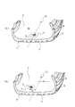
- FIG. 1 (a) and 1 (b) are partially sectional perspective views showing an embodiment of the pneumatic tire of the present invention.
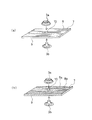
- FIG. 2A and FIG. 2B are for explaining an embodiment of the pneumatic tire of the present invention, and can be separated into two machines used for the pneumatic tire of the present invention. It is an appearance perspective model figure explaining the state where two members which constitute one mechanical fastener of the mechanical fasteners are engaged with each other with a single layer of rubber-coated fiber reinforcement interposed therebetween.
- 3 (a) and 3 (b) are for explaining another embodiment of the pneumatic tire of the present invention, and are divided into two parts used in the pneumatic tire of the present invention.
- FIG. 4A and FIG. 4B are model diagrams for explaining an angle ⁇ formed by the direction in which the fiber bundles in the fiber reinforcement are arranged with respect to the tire circumferential direction X.
- FIG. 5 is a plan view for explaining an example of the shape of a preferred fiber reinforcing material 7 that can be used in the present invention, and in particular, for explaining the number of fiber bundles.
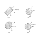
- FIGS. 7 (a) to 7 (d) are plan views for explaining an example of a preferable shape of the fiber reinforcing material 7 that can be used in the present invention, and in particular, a contour shape when the fiber reinforcing material 7 is viewed in plan view. Is described.
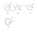
- FIGS. 7 (a) to 7 (d) are plan views for explaining one example of a preferable shape of the mechanical fastener 3 that can be used in the present invention. In particular, the mechanical fastener 3 is viewed in plan view. The outline shape will be described.
- the pneumatic tire 1 of the present invention is a mechanical fastener 3 of a pair of mechanical fasteners that can be separated into two on the tire inner surface 2, and at least two of them.
- the mechanical fastener composed of the above fastener constituent members 3a and 3b FIGS. 2 and 3
- the two or more fastener constituent members 3a, 3b are fixed with a rubber-coated fiber reinforcement 7 interposed therebetween
- the installation position of the mechanical fastener 3 is such that the distance D (mm) in the tire width direction between the center position C of the mechanical fastener 3 and the tire equator line CL is the maximum width W (mm ) Satisfies the relationship 0 ⁇ D / W ⁇ 0.40
- the fiber reinforcement 7 is formed by arranging a plurality of fiber bundles 8 in at least one direction, and the number Y of fiber bundles per unit width of the fiber reinforcement (line / 50 mm width) ) Is 20 ⁇ Y (book / 50 mm width) ⁇ 90, It is characterized by that.
- 4 is a tread portion
- 5 is a sidewall portion
- 6 is a bead portion.
- FIG. 2A is an external perspective model diagram illustrating a state in which the fiber reinforcing members 7 are engaged with each other with the intermediate portion interposed therebetween, and FIG. 2A is a fiber reinforcing member in which the fiber bundles 8 are arranged in one direction and are covered with rubber; 7 is formed, and FIG. 2B shows a case where the fiber bundles 8a and 8b are arranged in two directions and one layer of fiber reinforcing material is formed.
- reference numeral 10 denotes a hole through which the mechanical fastener 3 provided in the fiber reinforcement 7 is passed.
- FIG. 3 (a) is a perspective view of an external appearance of the fiber reinforcing material 7a and 7b, and a part of the fiber reinforcing material 7a is shown in FIG. 3 (a).
- 81 and the fiber bundle 82 of the fiber reinforcing material 7b cross each other at an intersecting angle of approximately 45 degrees so that they are arranged and covered with a rubber coating 9 to form the fiber reinforcing material 7.
- FIG. 3 (b) shows a case where the fiber reinforcing material 7 is formed such that the fiber bundle 81 of the fiber reinforcing material 7a and the fiber bundle 82 of the fiber reinforcing material 7b intersect with each other at an intersection angle of approximately 90 degrees. Yes.
- the mechanical fastener can be separated into two fasteners 3 and can be physically engaged again, and this engagement and separation can be repeated freely. It is composed of a pair of fasteners that can be used in the same manner, and is basically the same as that described in Patent Documents 3 and 4 described above.
- Typical examples are mechanical fasteners called hooks or snaps, which are generally used in the clothing industry, and more specifically, snap buttons, ring snaps, ring hooks, American snaps, American hooks, eyelet hooks, spring hooks. It is a collective term for what is called a jumper hook.
- such a mechanical fastener has a small area (for example, preferably about 1 to 115 mm 2, etc.). it is of about 4 ⁇ 90 mm 2), in which it were referred punctate fasteners. That is, for example, even in a small area of about 1 to 115 mm 2 or the like, strong engagement is achieved by a mechanical male and female structure or the like, and the structure itself may be of a known structure. .
- the material is made of metal, rubber, synthetic resin or the like.
- the installation position of the mechanical fastener 3 is set such that the distance D (mm) in the tire width direction between the center position C of the mechanical fastener 3 and the tire equator line CL is the maximum width W (mm ) With respect to the region satisfying the relationship of 0 ⁇ D / W ⁇ 0.40, on which the two or more fastener constituent members 3a and 3b are sandwiched with rubber-coated material 7 And a plurality of fiber bundles 8 are arranged in at least one direction as the fiber reinforcement 7, and the number Y of fiber bundles per unit width of the fiber reinforcement ( By using the fiber reinforcing material 7 in which the book / 50 mm width) is 20 ⁇ Y (book / 50 mm width) ⁇ 90, the engagement force obtained as a mechanical fastener is large and the magnitude of the engagement force is large.
- the mechanical fastener is attached to the tire inner surface as the tire usage time passes. This is not preferable because the functional object cannot maintain the initial arrangement state at the correct position and correctly on the inner surface of the tire, and the function cannot be exhibited.
- the fiber reinforcing material 7 includes a plurality of fiber bundles 8 arranged in at least one direction, and the number Y of fiber bundles per unit width of the fiber reinforcing material (width / 50 mm width) is It is important to use a fiber reinforcement 7 that satisfies 20 ⁇ Y (width / 50 mm width) ⁇ 90.
- the number of fiber bundles Y (unit / 50 mm width) per unit width of the fiber reinforcing material is less than 20/50 mm width, the effect of increasing the attachment strength can be sufficiently obtained by providing the fiber reinforcing material.
- the width is greater than 90/50 mm, generally, the difference in rigidity from the peripheral tire inner surface where the fiber reinforcing material is not present becomes too large, which is not preferable.
- the installation position of the mechanical fastener 3 is the distance in the tire width direction between the center position C of the mechanical fastener 3 and the tire equator line CL, as shown in FIGS. 1 (a) and 1 (b). It is important that D (mm) is within a region satisfying the relationship of 0 ⁇ D / W ⁇ 0.40 with respect to the maximum width W (mm) of the tire, and in particular, the mechanical fastener When the object having a specific function attached through the tire has a height of 15 mm or more, the pendulum movement of the object is likely to be induced by the tire inner surface distortion. Therefore, the above-described 0 ⁇ D / W ⁇ 0.40 It is important to satisfy the relationship. In the region satisfying the relationship of 0 ⁇ D / W ⁇ 0.40, the distortion of the tire inner surface during rolling of the tire is relatively small (particularly, the distortion in the tire width direction is small). This is important because the dropout is in the direction of decreasing.
- the pneumatic tire of the present invention since an object desired to be attached to the inner surface can be engaged and attached via a pair of mechanical fasteners, a physically obtained engagement force is large, In addition, there is no variation in the magnitude of the engagement force (positional variation within the tire, variation between tires). Further, even under severe use conditions that are repeated for a long time, the engagement force is less likely to deteriorate or decrease over time. Therefore, it is possible to maintain a desired engagement force for a long period of time, and to exhibit the function of the object attached to the inner surface for a long period of time.
- the positioning of the engagement position (engagement point) between the tire inner surface and the mounting object is automatically and accurately performed in accordance with the installation position of the fastener on the tire inner surface. It is possible to easily cope with cases where a high degree of accuracy is required. This is significant because it is in a narrow curved surface of the tire inner surface.
- the fiber bundle constituting the fiber reinforcing material is preferably composed of a fiber bundle having a Young's modulus of 1 to 15 GPa.
- the rubber-coated fiber reinforcement material realizes a relatively flexible rubber-based composite material, and the fiber reinforcement material is used for tire rolling. This is because it is possible to follow the rolling strain repeatedly applied by the movement, and thus excellent durability can be obtained.
- the preferable range of the Young's modulus is 2 to 8 GPa.
- the fiber bundle of nylon 6 is 4 GPa and falls within the preferable range.
- the rolling distortion in the tire circumferential direction is larger than the distortion in the tire width direction.
- the rolling distortion repeatedly applied by the rolling of the tire includes the distortion in the tire circumferential direction and the distortion in the tire width direction. More preferably, the material is formed by arranging a plurality of fiber bundles in two or more directions (FIGS. 2B, 3A, and 3B).
- the arrangement direction of the fiber bundles in the fiber reinforcement described above is at least an angle formed with the tire circumferential direction as the arrangement direction in any of the arrangement directions in one direction and in at least two directions. It is preferable that a fiber bundle exhibiting 15 degrees ⁇ ⁇ ⁇ 75 degrees as (inferior angle ⁇ ) is present.
- the mechanical fastener is provided in a region satisfying the relationship of 0 ⁇ D / W ⁇ 0.40.
- rolling distortion repeatedly applied by tire rolling is The tire circumferential direction distortion and the tire width direction distortion exist, and the tire circumferential direction distortion is larger than the tire width direction distortion particularly in the tire equator and the vicinity thereof. It is effective to make an angle in the arrangement direction of the fiber bundles with respect to the circumferential direction, and it is preferable to set the angle (subordinate angle) ⁇ to the tire circumferential direction to 15 degrees ⁇ ⁇ ⁇ 75 degrees, and stress due to strain It can reduce, and the effect which provided the fiber reinforcement 7 can be exhibited more largely.
- the angle (recess angle ⁇ ) formed with the more preferable tire circumferential direction is 30 ° ⁇ ⁇ ⁇ 60 °, and the more preferable region where the mechanical fastener is provided is 0 ⁇ . It is an area
- region of D / W ⁇ 0.2.
- FIG. 4A shows that the fiber bundles 8 are arranged in one direction as shown in FIG.
- the fiber bundles 8 arranged in one direction with respect to the tire circumferential direction X form an angle (inferior angle) ⁇ with the tire circumferential direction.
- the diagram shown on the right side of FIG. 4A is an enlarged model view of the diagram shown on the left side of FIG. 4 (b) shows an example in which the fiber bundles 81 and 82 are arranged in two directions as shown in FIGS. 3 (a) and 3 (b), and the fiber bundle 81, 82 form angles (recess angles) ⁇ 1 and ⁇ 2 with the tire circumferential direction, respectively.
- the diagram shown on the right side of FIG. 4B is a model enlarged view of the diagram shown on the left side of FIG.
- the fiber bundles 81 and 82 are arranged in at least two directions, of at least two angles (subordinate angles) ⁇ 1 and ⁇ 2 formed with the tire circumferential direction.
- the fiber reinforcing material 7 may be configured so that at least one of them exhibits 15 degrees ⁇ ⁇ ⁇ 75 degrees.
- the fibers constituting the fiber reinforcing material are preferably made of long fibers (filament fibers) of chemical fibers or synthetic fibers from the viewpoint of high physical properties and quality stability.
- An aligning sheet, a braided woven fabric, a plain woven fabric, or the like can be particularly preferably used from the viewpoint of high strength and high durability.
- the range of the basis weight described above is preferable because the rubber is easily impregnated between fibers or fiber bundles while securing the attachment durability, and strong vulcanized adhesion is easily obtained.
- a more preferred basis weight is 30 to 200 g / m 2 .
- the fiber is preferably a chemical fiber or a synthetic fiber such as rayon fiber, nylon fiber, polyester fiber, polyethylene fiber or the like because it can be stably obtained with high quality.
- the fiber bundle typically refers to a unit in which a plurality of fibers are gathered in a single thread shape.
- a plurality of thread-like ones may be combined together by being aligned or twisted together, and may be handled as one.
- the average length L (mm) of the fiber bundles in the fiber reinforcement passing through the fastener region 11 where the fastener 3 is projected on the tire inner surface is preferably 15 ⁇ L (mm) ⁇ 200. . 4 (a) and 4 (b), the fiber bundle passing through the fastener region 11 in which the fastener 3 is projected onto the tire inner surface is 811 in FIG. 4 (a) and FIG. 4 (b). 811 and 821, and each fiber bundle is divided by a hole 10 through which the mechanical fastener 3 provided in the fiber reinforcement 7 is passed. It is preferable that the average length L (mm) of the length of the fiber bundle in the fiber reinforcing material after the division is in the range of 15 ⁇ L (mm) ⁇ 200.
- the length of the fiber bundle that functions to restrain the mechanical fastener to the inner surface of the tire has a lower limit for producing a stable fixing force.
- the lower limit is 15 mm.
- the upper limit is 200 mm. is there.
- it is more preferably in a range of 60 ⁇ L (mm) ⁇ 90.
- the number of fiber bundles in the fiber reinforcing material 7 passing through the fastener region 11 obtained by projecting the fastener on the tire inner surface is 4 to 90.
- the fiber reinforcement that has the function of holding the mechanical fasteners on the inner surface of the tire has a lower number of fiber bundles to produce a more stable fixing force.
- the number is preferably 4 to 90, more preferably 8 to 30.
- the number of fiber bundles in the fiber reinforcing material 7 that passes through the fastener region 11 is the total number of fiber bundles that pass in all directions. For example, in the example of the model shown in FIG. There are six as shown by the numbers.
- the fiber reinforcing material 7 has a contour shape when the fiber reinforcing material 7 is viewed in a plan view, does not have a sharp corner, and is constituted by a curve having a curvature radius of 5 mm or more, or the curvature radius is 5 mm or more. It is preferable that it is comprised by the combination of these curves and a straight line. Examples of specific shapes are shown in FIGS. 6A, 6B, 6C, and 6D. As shown here, a rectangular shape such as a rectangle with rounded corners or a square, a circular shape, an elliptical shape, a regular polygonal shape such as a regular hexagon with rounded corners, etc. This is a preferred shape example.
- the distance R from the contour shape of the fastener 3 projected onto the tire inner surface to an arbitrary point on the contour line farthest from the center of gravity of the contour shape is 2 to 60 mm. Is preferred.
- the diameter of the fastener attached to the inner surface of the tire has a size that becomes the lower limit in order to secure the fixing strength, but if it is too large, the risk of vulcanization failure during the production of the pneumatic tire increases, so the upper limit According to the knowledge of the present inventors, the above-mentioned distance R is 2 to 60 mm.
- the adhesion area S (cm 2 ) of the fiber reinforcement 7 to the tire inner surface preferably satisfies 12 ⁇ S (cm 2 ) ⁇ 300.
- 12 ⁇ S (cm 2 ) ⁇ 300 there is a risk that stress due to strain increases and the member may fall off.
- 12 cm 2 it is difficult to obtain a stable fixing force, which is not preferable.
- an object having the other fastener of the pair of mechanical fasteners is engaged with the fastener 3 which is a pair on the tire inner surface side, whereby the inner surface of the pneumatic tire is obtained. It is arranged.
- the object having the other fastener can be configured to have various functions in accordance with recent high-tech pneumatic tires.
- an electronic circuit including a sensor, b) Balance weight, (c) Run flat core, (d) Oxygen scavenger, Desiccant, and / or object on which UV detecting color former is applied or mounted, (e) Sound absorbing material, (f) Hook fastener member, etc.
- An object such as any one of these or a combination of a plurality of them is a typical one.
- Examples 1 to 8, Comparative Examples 1 to 3 As the mechanical fastener member, the one shown in FIG. 7 (a) is used, and various fiber reinforcements shown in Table 1 are used, as shown in FIG. 2 (a) and FIG. 3 (b).
- One mechanical fastener member 3 was vulcanized and bonded to the equator portion of the inner peripheral surface of the tread portion of the pneumatic tire (195 / 65R15) in the vulcanization molding process of the pneumatic tire (195 / 65R15).
- the maximum width of the pneumatic tire is 195 mm (Examples 1 to 8, Comparative Examples 1 to 3).
- the fixing position of the fastener and the properties of the fiber reinforcement are as shown in Table 1.
- the fastener durability test and evaluation method were conducted as follows. (1) Durability test of fasteners A weight having a weight of 100 g was fixed to the mechanical fasteners on the inner surface of each test tire using the other pair of mechanical fasteners. In that state, a drum running endurance test was performed, and the running distance until the fastener on the tire inner surface fell off from the inner surface was obtained. The running distance of Comparative Example 1 using only the rubber sheet without using the fiber reinforcement was used. As the index 100, those of other examples and comparative examples were evaluated. The index is better as it is greater than 100, indicating that it was able to travel a long distance.
- the test tire (195 / 65R15) is a forced test in which the air pressure is 210 kPa, the running speed is 81 km / hour, and the load is increased by 13% of the maximum load load every 2 hours.
- the pneumatic tire according to the present invention is excellent in that the fixing strength of the mechanical fastener is very large.
Landscapes
- Engineering & Computer Science (AREA)
- Mechanical Engineering (AREA)
- Tires In General (AREA)
Abstract
留め具(3)のタイヤ内面への取り付け強度が大きく、機能性物体を長期にわたり取り付けて維持するのに有効な、留め具(3)を内部に有した空気入りタイヤ(1)を提供する。タイヤ内面に、2つに分離できる一対の留め具(3)のうちの一方の留め具(3)であって、2つ以上の留め具(3)構成部材から構成される留め具(3)が設置されていなる空気入りタイヤ(1)において、 (a)該2つ以上の留め具(3)構成部材がゴム被覆された繊維補強材を挟んで固定され、 (b)該留め具(3)の設置位置が、該留め具(3)の中心位置(C)とタイヤ赤道線(L)とのタイヤ幅方向の距離(D)が、該タイヤの最大幅(W)に対して、0≦D/W≦0.40の関係を満足し、 (c)該繊維補強材は、複数本の繊維束が少なくとも1方向に配列されて形成されてなり、該繊維補強材の単位幅当たりの繊維束本数Y(本/50mm幅)が、20≦Y(本/50mm幅)≦90である。
Description
本発明は空気入りタイヤに関し、さらに詳しくは、空気入りタイヤの内面に物体を強固に取付けることができる空気入りタイヤに関する。
近年、空気入りタイヤの内面に、さまざまな特定機能を有する物体を配設することが種々検討されてきている。
たとえば、生タイヤのインナーライナー等に、フック・アンド・ループ留め具あるいはフック・アンド・フック留め具等の、所謂、面ファスナーを用いてタイヤタグ(高周波識別タグ)、チップあるいは吸音材等を取付けるという取付け方法が提案されている(特許文献1,2)。
これら特許文献1,2に提案されている面ファスナーは、取付け時において比較的強い係合力を実現し、また、取付け作業の際にも多少の位置的なズレなどを問題にせずに面状での係合を実現できる点で好ましいものである。しかし、比較的温度が高めの状況のもとで高速での転動による変形と圧縮が長時間繰り返されることにより、部分的な物理的劣化の発生とそれが進行していくことによる面ファスナー全体の係合力の経時的な劣化・低下が生じて、所望どおりの係合力を長期間にわたって維持することが難しい場合があるという問題があった。
これに対して、本発明者らは、タイヤ内面に、2つに分離できる一対の機械的留め具のうちの一方の留め具を有する空気入りタイヤを提案した(特許文献3,4)。この空気入りタイヤでは、上述の問題がなく、特に得られる係合力が大きくかつその大きさにばらつき(該タイヤ内での位置的なばらつきや、タイヤ間でのばらつき)が生じることがほとんどなく、さらに比較的高温下かつ高速でのタイヤ転動に伴う変形と圧縮が長時間繰り返される過酷な使用条件によっても、その係合力に経時的な劣化や低下が生ずることが少なく、長期にわたり所望の係合力を維持できる。
この機械的留め具を用いる方式は、得られる係合力の大きさ、かつその大きさのばらつきや、係合作業の確実さなどの点で優れたものであり、このタイヤ内面へ一方の留め具を設けるための取り付け方法について、本発明者らは、トレッドゴムに該留め具を1個1個埋め込んで加硫により行うこと、また、2つに分離できる一対の機械的留め具のうちの、タイヤ内面に設けられる一方の機械的留め具を少なくとも2つ以上の留め具構成部材から構成される機械的留め具として、該2つ以上の留め具構成部材をゴム層あるいはゴムで被覆された繊維補強材を挟んで固定することを提案した(特許文献3)。
また、該2つ以上の留め具構成部材を繊維からなる織布や不織布を挟んで固定することを提案した(特許文献4)。
しかし、それらの方法では、留め具の形状や取り付け位置によっては、所望通りの取り付け強度が得られない場合があるという問題、ひいては、特定の機能を有する物体を配設した空気入りタイヤとしての耐久性が低下するという問題があった。
この機械的留め具の取り付け強度は、タイヤ内に配設される特定の機能を有する物体の固有の性状(重さ、大きさ、形状など)にも応えることができるように、より高くかつ長寿命であることが要請されるのである。
上述したような点に鑑み、本発明の目的は、得られる係合力が大きくかつその係合力の大きさにばらつき(該タイヤ内での位置的なばらつき。タイヤ間でのばらつき)が生じることがほとんどなく、さらに比較的高温下かつ高速でのタイヤ転動に伴う変形と圧縮が長時間繰り返される過酷な使用条件等によっても、その係合力に経時的な劣化や低下が生ずることが少ないという機械的留め具を実現し、かつ、その機械的留め具のタイヤ内面への取り付け強度が大きく、特定の機能と固有の性状(重さ、大きさ、形状など)を有する所望の機能性物体を長期にわたり取り付けて維持するのに有効な、機械的留め具をタイヤ内部に有した空気入りタイヤを提供することにある。
上述した目的を達成する本発明の空気入りタイヤは、以下の(1)の構成を有する。
(1)タイヤ内面に、2つに分離できる一対の機械的留め具のうちの一方の機械的留め具であるとともに、少なくとも2つ以上の留め具構成部材から構成される機械的留め具が設置されてなる空気入りタイヤにおいて、
(a)該2つ以上の留め具構成部材がゴム被覆された繊維補強材を挟んで固定されていて、
かつ、
(b)該機械的留め具の設置位置が、該機械的留め具の中心位置Cとタイヤ赤道線Lとのタイヤ幅方向の距離D(mm)が、該タイヤの最大幅W(mm)に対して、0≦D/W≦0.40の関係を満足し、
さらに、
(c)前記繊維補強材は、複数本の繊維束が少なくとも1方向に配列されて形成されてなるものであり、該繊維補強材の単位幅当たりの繊維束本数Y(本/50mm幅)が、20≦Y(本/50mm幅)≦90である、
ことを特徴とする空気入りタイヤ。
(1)タイヤ内面に、2つに分離できる一対の機械的留め具のうちの一方の機械的留め具であるとともに、少なくとも2つ以上の留め具構成部材から構成される機械的留め具が設置されてなる空気入りタイヤにおいて、
(a)該2つ以上の留め具構成部材がゴム被覆された繊維補強材を挟んで固定されていて、
かつ、
(b)該機械的留め具の設置位置が、該機械的留め具の中心位置Cとタイヤ赤道線Lとのタイヤ幅方向の距離D(mm)が、該タイヤの最大幅W(mm)に対して、0≦D/W≦0.40の関係を満足し、
さらに、
(c)前記繊維補強材は、複数本の繊維束が少なくとも1方向に配列されて形成されてなるものであり、該繊維補強材の単位幅当たりの繊維束本数Y(本/50mm幅)が、20≦Y(本/50mm幅)≦90である、
ことを特徴とする空気入りタイヤ。
また、かかる本発明の空気入りタイヤにおいて、好ましくは、以下の(2)~(13)のいずれかの構成を有するものである。
(2)前記繊維補強材が、繊維束1本当たりの繊維断総面積A(mm2/繊維束)が0.05≦A(mm2/繊維束)≦1.20である繊維束を含んでなることを特徴とする上記(1)記載の空気入りタイヤ。
(3)前記繊維補強材が、ヤング率1~15GPaである繊維束から構成されていることを特徴とする上記(1)または(2)記載の空気入りタイヤ。
(4)前記繊維補強材が、複数本の繊維束が1方向に配列されて形成されてなるものであることを特徴とする上記(1)~(3)のいずれかに記載の空気入りタイヤ。
(5)前記繊維補強材が、複数本の繊維束が2方向以上に配列されて形成されてなるものであることを特徴とする上記(1)~(3)のいずれかに記載の空気入りタイヤ。
(6)複数本の繊維束が1方向に配列されて形成されてなる繊維補強材が、該繊維束配列方向が相互に交差する方向のもとで複数層使用されることによって、2方向以上に繊維束が配列された状態を構成してなることを特徴とする上記(5)に記載の空気入りタイヤ。
(7)前記繊維補強材中の繊維束が配列されている方向が、タイヤ周方向となす角度(劣角θ)として15度≦θ≦75度であることを特徴とする上記(4)~(6)のいずれかに記載の空気入りタイヤ。
(8)前記留め具を前記タイヤ内面に投影した留め具領域を通過する前記繊維補強材中の繊維束の平均長さL(mm)が、15≦L(mm)≦200であることを特徴とする上記(1)~(7)のいずれかに記載の空気入りタイヤ。
(9)前記留め具を前記タイヤ内面に投影した留め具領域を通過する前記繊維補強材中の繊維束の本数が、4~90本であることを特徴とする上記(1)~(8)のいずれかに記載の空気入りタイヤ。
(10)前記2つ以上の留め具構成部材に挟み込まれる繊維補強材が、該繊維補強材を平面視したときの輪郭形状が、鋭利な角部を持たず、曲率半径が5mm以上の曲線で構成されているか、あるいは該曲率半径が5mm以上の曲線と直線の組み合わせによって構成されているものであること特徴とする上記(1)~(9)のいずれかに記載の空気入りタイヤ。
(11)前記留め具を前記タイヤ内面に投影した該留め具の輪郭形状が、該輪郭形状の重心位置から最も遠い該輪郭線上の任意の点までの距離Rが2~60mmであることを特徴とする上記(1)~(10)のいずれかに記載の空気入りタイヤ。
(2)前記繊維補強材が、繊維束1本当たりの繊維断総面積A(mm2/繊維束)が0.05≦A(mm2/繊維束)≦1.20である繊維束を含んでなることを特徴とする上記(1)記載の空気入りタイヤ。
(3)前記繊維補強材が、ヤング率1~15GPaである繊維束から構成されていることを特徴とする上記(1)または(2)記載の空気入りタイヤ。
(4)前記繊維補強材が、複数本の繊維束が1方向に配列されて形成されてなるものであることを特徴とする上記(1)~(3)のいずれかに記載の空気入りタイヤ。
(5)前記繊維補強材が、複数本の繊維束が2方向以上に配列されて形成されてなるものであることを特徴とする上記(1)~(3)のいずれかに記載の空気入りタイヤ。
(6)複数本の繊維束が1方向に配列されて形成されてなる繊維補強材が、該繊維束配列方向が相互に交差する方向のもとで複数層使用されることによって、2方向以上に繊維束が配列された状態を構成してなることを特徴とする上記(5)に記載の空気入りタイヤ。
(7)前記繊維補強材中の繊維束が配列されている方向が、タイヤ周方向となす角度(劣角θ)として15度≦θ≦75度であることを特徴とする上記(4)~(6)のいずれかに記載の空気入りタイヤ。
(8)前記留め具を前記タイヤ内面に投影した留め具領域を通過する前記繊維補強材中の繊維束の平均長さL(mm)が、15≦L(mm)≦200であることを特徴とする上記(1)~(7)のいずれかに記載の空気入りタイヤ。
(9)前記留め具を前記タイヤ内面に投影した留め具領域を通過する前記繊維補強材中の繊維束の本数が、4~90本であることを特徴とする上記(1)~(8)のいずれかに記載の空気入りタイヤ。
(10)前記2つ以上の留め具構成部材に挟み込まれる繊維補強材が、該繊維補強材を平面視したときの輪郭形状が、鋭利な角部を持たず、曲率半径が5mm以上の曲線で構成されているか、あるいは該曲率半径が5mm以上の曲線と直線の組み合わせによって構成されているものであること特徴とする上記(1)~(9)のいずれかに記載の空気入りタイヤ。
(11)前記留め具を前記タイヤ内面に投影した該留め具の輪郭形状が、該輪郭形状の重心位置から最も遠い該輪郭線上の任意の点までの距離Rが2~60mmであることを特徴とする上記(1)~(10)のいずれかに記載の空気入りタイヤ。
(12)タイヤ内面にある前記一方の留め具に係合する他方の留め具を有する物体を、それら2つの留め具を係合させることによりタイヤ内面に固定してなることを特徴とする上記(1)~(11)のいずれかに記載の空気入りタイヤ。
(13)前記他方の留め具を有する物体が、(a)センサーを含む電子回路、(b)バランスウェイト、(c)ランフラット中子、(d)脱酸素剤、乾燥剤および/または紫外線検知発色剤を塗布または搭載した物体、(e)吸音材、(f)面ファスナー部材、のいずれか一つかまたはそれらの複数を組合せた物体であることを特徴とする上記(12)に記載の空気入りタイヤ。
(13)前記他方の留め具を有する物体が、(a)センサーを含む電子回路、(b)バランスウェイト、(c)ランフラット中子、(d)脱酸素剤、乾燥剤および/または紫外線検知発色剤を塗布または搭載した物体、(e)吸音材、(f)面ファスナー部材、のいずれか一つかまたはそれらの複数を組合せた物体であることを特徴とする上記(12)に記載の空気入りタイヤ。
請求項1にかかる本発明によれば、機械的留め具として得られる係合力が大きくかつその係合力の大きさにばらつき(該タイヤ内での位置的なばらつき。タイヤ間でのばらつき)が生じることもほとんどなく、さらに比較的高温下かつ高速でのタイヤ転動に伴う変形と圧縮が長時間繰り返される過酷な使用条件等によっても、その係合力に経時的な劣化や低下が生ずることが少ないという機械的留め具を実現し、かつ、その上で、その機械的留め具自体のタイヤ内面への取り付け強度が大きな機械的留め具を有する空気入りタイヤを実現することができる。
したがって、請求項1にかかる本発明によれば、それらの効果が合わさって、特定の機能と固有の性状(重さ、大きさ、形状など)を有する各種の所望の機能性物体を、その性状等によって限定などほとんどされることなく、長期にわたりタイヤ内部に取り付けて、その機能を維持発揮させることができる、優れた機械的留め具をタイヤ内部に有する空気入りタイヤが実現されるものである。
請求項2~請求項11のいずれかにかかる本発明の空気入りタイヤによれば、上述した請求項1にかかる本発明で得られる効果を、より明確にかつより大きく得られる点で優れた空気入りタイヤが実現されるものである。
請求項12もしくは請求項13にかかる本発明によれば、タイヤ内面に、所望の機能を有する特定の機能性物体を大きな係合力と優れたその耐久性を実現しつつ取付けることができる新規な空気入りタイヤ、もしくは、該機能性物体を取り付けた新規な空気入りタイヤが実現されるものである。
以下、図面などを用いながら、更に詳しく本発明の空気入りタイヤについて説明する。
図1に示したように、本発明の空気入りタイヤ1は、タイヤ内面2に、2つに分離できる一対の機械的留め具のうちの一方の機械的留め具3であるとともに、少なくとも2つ以上の留め具構成部材3a、3b(図2、図3)から構成される機械的留め具が設置されてなる空気入りタイヤにおいて、図2、図3に示したように、
(a)該2つ以上の留め具構成部材3a、3bがゴム被覆された繊維補強材7を挟んで固定されていて、
かつ、
(b)該機械的留め具3の設置位置が、該機械的留め具3の中心位置Cとタイヤ赤道線CLとのタイヤ幅方向の距離D(mm)が、該タイヤの最大幅W(mm)に対して、0≦D/W≦0.40の関係を満足し、
さらに、
(c)該繊維補強材7は、複数本の繊維束8が少なくとも1方向に配列されて形成されてなるものであり、該繊維補強材の単位幅当たりの繊維束本数Y(本/50mm幅)が、20≦Y(本/50mm幅)≦90である、
ことを特徴とする。図1において、4はトレッド部、5はサイドウォール部、6はビード部である。
(a)該2つ以上の留め具構成部材3a、3bがゴム被覆された繊維補強材7を挟んで固定されていて、
かつ、
(b)該機械的留め具3の設置位置が、該機械的留め具3の中心位置Cとタイヤ赤道線CLとのタイヤ幅方向の距離D(mm)が、該タイヤの最大幅W(mm)に対して、0≦D/W≦0.40の関係を満足し、
さらに、
(c)該繊維補強材7は、複数本の繊維束8が少なくとも1方向に配列されて形成されてなるものであり、該繊維補強材の単位幅当たりの繊維束本数Y(本/50mm幅)が、20≦Y(本/50mm幅)≦90である、
ことを特徴とする。図1において、4はトレッド部、5はサイドウォール部、6はビード部である。
図2(a)および図2(b)は、2つに分離できる機械的留め具のうちの一方の機械的留め具3を構成する2つの部材3a、3bを、1層のゴム被覆された繊維補強材7を中間に挟んで互いに係合させる状態を説明する外観斜視モデル図であり、図2(a)は、繊維束8が1方向に配列されてゴム被覆9がされて繊維補強材7が形成されているものであり、図2(b)は、繊維束8a、8bが2方向の配列状態を呈して、一層の繊維補強材が形成されている場合を示している。図2、図3において、10は繊維補強材7に設けられた機械的留め具3を通すための孔である。
図3(a)および図3(b)は、2つに分離できる機械的留め具のうちの一方の機械的留め具3を構成する2つの部材3a、3bを、2層のゴム被覆された繊維補強材7a、7bを中間に挟んで互いに係合させる状態を説明するため、一部を破砕して示した外観斜視モデル図であり、図3(a)は、繊維補強材7aの繊維束81と繊維補強材7bの繊維束82とが互いにほぼ45度の交差角度で交わるようにして、それぞれが配列されてゴム被覆9がされて繊維補強材7が形成されているものであり、図3(b)は、繊維補強材7aの繊維束81と繊維補強材7bの繊維束82とが互いにほぼ90度の交差角度で交わるようにして繊維補強材7が形成されている場合を示している。
ここで、本発明において、機械的留め具とは、2つの留め具3に分離することができ、かつそれらを再度、物理的に係合させることができ、この係合と分離を繰返して自在に行える一対の留め具で構成されるものであり、前述した特許文献3,同4で記載しているものと基本的に同様なものである。その代表的なものとして、ホックあるいはスナップと呼ばれる機械的留め具があり、衣料業界等で一般に、より具体的には、スナップボタン、リングスナップ、リングホック、アメリカンスナップ、アメリカンホック、アイレットホック、バネホックおよびジャンパーホックと呼ばれるもの等を総称して言う。
こうした機械的留め具は、係合箇所の面積が全面積で無限である所謂「面ファスナー」とは相違して、係合箇所が小面積(例えば、好ましくは1~115mm2程度など。さらに好ましくは、4~90mm2程度)の、いわば点状の留め具をいうものである。すなわち、例えば、1~115mm2程度等の小面積での係合であっても機械的な雌雄構造等によって強い係合がなされるものであり、それ自体は公知の構造のものであってよい。その材質としては、金属製、ゴム製、合成樹脂製などのものである。
本発明においては、機械的留め具3の設置位置を、機械的留め具3の中心位置Cとタイヤ赤道線CLとのタイヤ幅方向の距離D(mm)が、該タイヤの最大幅W(mm)に対して、0≦D/W≦0.40の関係を満足する領域内として、その上で、該2つ以上の留め具構成部材3a、3bがゴム被覆された繊維補強材7を挟んで固定されるようにして、かつ、該繊維補強材7として、複数本の繊維束8が少なくとも1方向に配列されて形成されていて、該繊維補強材の単位幅当たりの繊維束本数Y(本/50mm幅)が、20≦Y(本/50mm幅)≦90である繊維補強材7を使用することにより、機械的留め具としての得られる係合力が大きくかつその係合力の大きさにばらつき(該タイヤ内での位置的なばらつきや、タイヤ間でのばらつき)が生じることがほとんどなく、さらに比較的高温下かつ高速でのタイヤ転動に伴う変形と圧縮が長時間繰り返される過酷な使用条件等によっても、その係合力に経時的な劣化や低下が生ずることが少ないという機械的留め具を実現するとともに、かつ、その機械的留め具のタイヤ内面への取り付け強度が大きく、特定の機能と固有の性状(重さ、大きさ、形状など)を有する所望の機能性物体を長期にわたり取り付けて維持するのに有効な、機械的留め具を内部に有した空気入りタイヤを実現できる。
特に、機械的留め具としての係合力だけを大きくしても、その機械的留め具のタイヤ内面への取り付け強度が小さい場合には、タイヤの使用時間が経っていくにつれて、タイヤ内面に取り付けられた機能性物体が、タイヤ内面上で正しい位置でかつ正しく立った初期の配設状態を維持できなくなり、その機能を発揮できなくなるので、好ましくない。
機械的留め具のタイヤ内面への取り付け強度を十分に高いものとする上で、2つ以上の留め具構成部材3a、3bがゴム被覆された繊維補強材7を挟んで固定されるようにして、かつ、該繊維補強材7としては、複数本の繊維束8が少なくとも1方向に配列されて形成されていて、該繊維補強材の単位幅当たりの繊維束本数Y(本/50mm幅)が、20≦Y(本/50mm幅)≦90である繊維補強材7を使用することが重要である。該繊維補強材の単位幅当たりの繊維束本数Y(本/50mm幅)が、20本/50mm幅未満の場合は、繊維補強材を設けたことにより取り付け強度を大きくする効果が十分に得られなくなり好ましくなく、90本/50mm幅よりも多いときは、一般に、該繊維補強材の存在しない周辺のタイヤ内面との剛性差が大きくなりすぎて好ましくない。
また、機械的留め具3の設置位置は、図1(a)及び図1(b)に示したように、機械的留め具3の中心位置Cとタイヤ赤道線CLとのタイヤ幅方向の距離D(mm)が、該タイヤの最大幅W(mm)に対して、0≦D/W≦0.40の関係を満足する領域内とすることが重要であり、特に、該機械的留め具を介して取り付けられる特定機能を有する物体が高さ15mm以上の大きさを有する場合は、タイヤ内面歪みによって物体の振り子運動が誘発されやすくなるため、上述した0≦D/W≦0.40の関係を満足することが重要である。0≦D/W≦0.40の関係を満足する領域内は、タイヤ転動中のタイヤ内面の歪みが比較的小さい(特に、タイヤ幅方向の歪みが小さい)ので、特定機能を有する物体の脱落が小さくなる方向であり重要なものである。
また、繊維補強材は、ゴム被覆されたものを使用することも重要であり、タイヤの加硫工程時には、タイヤのゴムと該ゴム被覆された繊維補強材が強固に加硫接合されるとともに、該繊維補強材自体も繊維間に含浸したゴムが加硫し、タイヤ内面と繊維補強材ひいては機械的留め具との接着・接合がより強くなされる。
かかる本発明の空気入りタイヤでは、その内面に取付けを所望する物体を、一対の機械的留め具を介して係合させて取り付けることができることになるので、物理的に得られる係合力が大きく、かつその係合力の大きさにばらつき(該タイヤ内での位置的なばらつき。タイヤ間でのばらつき)が生じることがない。さらに、長時間繰り返される過酷な使用条件によっても、その係合力に経時的な劣化や低下が生ずることが少ない。従って所望の係合力を長期にわたり維持すること、ひいては内面に取付けられた物体の機能を長期にわたり発揮させることができる。
その上、タイヤ内面と取付け物体の係合位置(係合点)の位置決めは、タイヤ内面の留め具の設置位置に対応して、自動的に正確に行なわれることとなり、該物体の設置位置(設置点)に高度な正確さが要請される場合にも簡単に対応することができる。これは、タイヤ内面という狭い湾曲面状の立体空間内でのことであるので意義は大きい。
本発明において、繊維補強材を構成する繊維束は、ヤング率が1~15GPaである繊維束から構成されていることが好ましい。ヤング率がかかる範囲内にある繊維束を使用することにより、ゴム被覆された繊維補強材は、比較的柔軟なゴム系複合材料を実現してなるものであり、該繊維補強材がタイヤの転動により繰り返し加えられる転動歪みに対して、より追従することができるので、優れた耐久性を得ることができるからである。該ヤング率の好ましい範囲は2~8GPaであり、例えば、ナイロン6の繊維束は4GPaであり、該好ましい範囲内に入るものである。
本発明において、繊維補強材は、複数本の繊維束が、少なくとも1方向に配列されて形成されてなるものを用いることが重要であり、その理由は、タイヤの転動により繰り返し加えられる転動歪みは、通常、少なくとも一つのほぼ一定方向のもとで繰り返し加えられるものだからである。特に、赤道上ないしはその付近の位置では、タイヤ幅方向の歪みよりもタイヤ周方向での転動歪みがより大きい。
ただ、タイヤの転動により繰り返し加えられる転動歪みは、タイヤ周方向での歪みとタイヤ幅方向での歪みが存在することは明らかであり、その2方向の歪みに対抗する上で、繊維補強材は、複数本の繊維束が2方向以上に配列されて形成されてなることが、さらに好ましい(図2(b)、図3(a)、図3(b))。
上述した繊維補強材中の繊維束の配列方向は、1方向で配列されている場合、少なくとも2方向で配列されている場合のいずれにおいても、少なくとも、その配列方向として、タイヤ周方向となす角度(劣角θ)として15度≦θ≦75度を呈する繊維束が存在するように構成することが好ましい。
本発明では、上述したように、0≦D/W≦0.40の関係を満足する領域内に機械的留め具を設けるが、この領域では、タイヤの転動により繰り返し加えられる転動歪みは、タイヤ周方向での歪みとタイヤ幅方向での歪みが存在するものであり、特に、タイヤ赤道とその付近の領域では、タイヤ周方向の歪みがタイヤ幅方向の歪みよりも大きいことから、タイヤ周方向に対して繊維束の配列方向に角度を持たせることが有効であり、タイヤ周方向となす角度(劣角)θとして15度≦θ≦75度とすることが好ましく、歪みによる応力を低減でき、繊維補強材7を設けた効果をより大きく発揮できるようになる。
本発明者らの各種知見によれば、より好ましいタイヤ周方向となす角度(劣角θ)は、30度≦θ≦60度であり、また、機械的留め具を設けるより好ましい領域は0≦D/W≦0.2の領域である。
上述した関係を、図4(a)および図4(b)にモデル図を示して説明すると、図4(a)は図2(a)に示したように繊維束8が一方向に配列している例を示し、タイヤ周方向Xに対して一方向に配列している繊維束8が、タイヤ周方向と角度(劣角)θをなしている。図4(a)の右側に示した図は、図4(a)の左側に示した図のモデル拡大図である。図4(b)は図3(a)および図3(b)に示したように繊維束81、82が2方向に配列している例を示し、タイヤ周方向Xに対して繊維束81、82が、それぞれタイヤ周方向と角度(劣角)θ1、θ2をなしている。この図4(b)の右側に示した図は、図4(b)の左側に示した図のモデル拡大図である。
この図4(b)に示したように、少なくとも繊維束81、82が少なくとも2方向に配列している例の場合は、タイヤ周方向となす少なくとも2つの角度(劣角)θ1、θ2のうち、少なくとも1つが15度≦θ≦75度を呈するようにして繊維補強材7を構成するとよい。
繊維補強材を構成する繊維は、高い物性と品質の安定性の点から化学繊維あるいは合成繊維の長繊維(フィラメント繊維)からなるものが好ましく、中でも、目付が20~300g/m2程度の繊維引き揃えシート、あるいはすだれ織物、平織物などが高強度、高耐久性などの点から特に好ましく使用することができる。特に、上述した目付の範囲であれば、取付け耐久性を確保しつつ、ゴムが繊維間あるいは繊維束間に含浸しやすく強力な加硫接着が得られやすいので好ましい。より好ましい目付は30~200g/m2である。繊維は、レーヨン繊維、ナイロン繊維、ポリエステル繊維、ポリエチレン繊維などの化学繊維あるいは合成繊維であることが高い品質で安定して得られる点で好ましい。
繊維束とは、代表的には、1本の糸状を呈して複数本の繊維が集合している単位のものをいう。あるいは、複数本の糸状のものが、引き揃えられてあるいは撚り合わせなどにより複合された形態のもので、1本として扱うことができるものでもよい。
本発明において、留め具3をタイヤ内面に投影した留め具領域11を通過する繊維補強材中の繊維束の平均長さL(mm)は、15≦L(mm)≦200であることが好ましい。これを図4(a)および図4(b)で説明すると、留め具3をタイヤ内面に投影した留め具領域11を通る繊維束は、図4(a)で811、図4(b)で811、821であり、各繊維束は、繊維補強材7に設けられた機械的留め具3を通すための孔10によって、分断されている。その分断された後の繊維補強材中の該繊維束の長さの平均長さL(mm)が、15≦L(mm)≦200の範囲内であることが好ましいのである。機械的留め具をタイヤ内面に抑えるために機能する繊維束の長さには、安定的な固定力を生むための下限があり、本発明者らの知見によれば該下限は15mmである。また、繊維束の長さが長すぎると、歪みによる応力が大きくなり、留め具、取り付け物体の脱落の危険性が生じてくるので、本発明者らの知見によれば、該上限は200mmである。また、留め具の取り付け強度を十分に得る上で、より好ましくは60≦L(mm)≦90範囲内である。
また、留め具をタイヤ内面に投影した留め具領域11を通過する繊維補強材7中の繊維束の本数は、4~90本であることが好ましい。機械的留め具をタイヤ内面に抑える機能を有する繊維補強材は、より安定的な固定力を生むために下限となる繊維束の本数があり、一方で、本数が多すぎると、繊維補強材の柔軟性がなくなってしまい、留め具、取り付け物体の脱落の危険性が生じてくるので、上限となる繊維束の本数がある。そのため、4~90本であることが好ましく、より好ましくは、8~30本である。ここで「留め具領域11を通過する繊維補強材7中の繊維束の本数」とは、全方向の通過する繊維束の合計本数であり、例えば、図5に示したモデルの例では、斜め数字で示したように6本である。
また、繊維補強材7は、繊維補強材7を平面視したときの輪郭形状が、鋭利な角部を持たず、曲率半径が5mm以上の曲線で構成されているか、あるいは該曲率半径が5mm以上の曲線と直線の組み合わせによって構成されているものであることが好ましい。具体的な形状例を図6(a)、図6(b)、図6(c)、図6(d)に示した。ここに示したように、角部を丸めた長方形あるいは正方形などの矩形状のもの、円形状のもの、楕円形状のもの、角部を丸めた正六角形状などの正多角形状のもの、などが好ましい形状例である。
また、機械的留め具3は、タイヤ内面に投影した該留め具3の輪郭形状が、該輪郭形状の重心位置から最も遠い該輪郭線上の任意の点までの距離Rが2~60mmであることが好ましい。タイヤ内面に装着される留め具の径は、固定強度を確保するために下限となる大きさがある一方で、大きすぎると空気入りタイヤ製造時における加硫故障の危険性が高くなるため、上限となる値が存在するものであり、本発明者らの知見によれば、上述した距離Rは2~60mmである。図7(a)、図7(b)、図7(c)、図7(d)に、それぞれ円形、三角形、楕円形、歯車形の場合を例にとり、重心位置から最も遠い該輪郭線上の任意の点までの距離Rを例示した。
繊維補強材7のタイヤ内面への接着面積S(cm2)は、12≦S(cm2)≦300、を満足することが好ましい。300cm2よりも大きいときは、歪みによる応力が大きくなり部材脱落につながる危険があり、12cm2よりも小さいときは、安定した固定力を得ることが難しくなり好ましくない。
本発明によれば、一対の機械的留め具のうちの、他方の留め具を有している物体が、タイヤ内面側の対である留め具3と係合されることによって空気入りタイヤの内面に配設される。
該他方の留め具を有している物体は、近年の空気入りタイヤのハイテク化に伴い、さまざまな機能を有したものとして構成することができ、例えば、(a)センサーを含む電子回路、(b)バランスウェイト、(c)ランフラット中子、(d)脱酸素剤、乾燥剤および/または紫外線検知発色剤を塗布または搭載した物体、(e)吸音材、(f)面ファスナー部材、などのいずれか一つかまたはそれらの複数を組合せた物体などが代表的なものである。
実施例1~8、比較例1~3
機械的留め具部材として、図7(a)に示した形態のものを用いて、表1に示した各種の繊維補強材を使用して、図2(a)、図3(b)に示した繊維補強材を空気入りタイヤ(195/65R15)のトレッド部内周面の赤道部に1個の機械的留め具部材3を該タイヤの加硫成形工程で加硫接着させて設けた。該空気入りタイヤの最大幅は195mmである(実施例1~8、比較例1~3)。
機械的留め具部材として、図7(a)に示した形態のものを用いて、表1に示した各種の繊維補強材を使用して、図2(a)、図3(b)に示した繊維補強材を空気入りタイヤ(195/65R15)のトレッド部内周面の赤道部に1個の機械的留め具部材3を該タイヤの加硫成形工程で加硫接着させて設けた。該空気入りタイヤの最大幅は195mmである(実施例1~8、比較例1~3)。
留め具の固定位置、繊維補強材の性状などは、表1に示したとおりである。

留め具の耐久性の試験と評価方法は、以下の通りの内容で行ったものである。
(1)留め具の耐久性の試験
各試験タイヤのタイヤ内面の機械的留め具に、重さ100gのウェイトを他方の対の機械的留め具を用いて固定した。その状態でドラム走行耐久試験を行い、タイヤ内面の留め具が該内面から脱落するまでの走行距離を求め、繊維強化材をもちいておらず、ゴムシートのみを用いた比較例1の走行距離を指数100として、他の実施例、比較例のものを指数評価した。指数は100よりも大きいほど優れていて、長い距離を走行できたことを示している。試験タイヤ(195/65R15)の空気圧は210kPa、走行速度は81km/時間、荷重を2時間ごとに最大負荷荷重の13%ずつ増加させていく強制試験である。
(1)留め具の耐久性の試験
各試験タイヤのタイヤ内面の機械的留め具に、重さ100gのウェイトを他方の対の機械的留め具を用いて固定した。その状態でドラム走行耐久試験を行い、タイヤ内面の留め具が該内面から脱落するまでの走行距離を求め、繊維強化材をもちいておらず、ゴムシートのみを用いた比較例1の走行距離を指数100として、他の実施例、比較例のものを指数評価した。指数は100よりも大きいほど優れていて、長い距離を走行できたことを示している。試験タイヤ(195/65R15)の空気圧は210kPa、走行速度は81km/時間、荷重を2時間ごとに最大負荷荷重の13%ずつ増加させていく強制試験である。
得られた各試験タイヤの結果からわかるように、本発明に係る空気入りタイヤは、機械的留め具の固定強度が非常に大きい優れたものである。
1:空気入りタイヤ
2:タイヤ内周面
3:機械的留め具
3a:機械的留め具の構成部材
3b:機械的留め具の構成部材
4:トレッド部
5:サイドウォール部
6:ビード部
7、7a、7b:ゴム被覆された繊維補強材
8、8a、8b:繊維束
81、82:繊維束
9:ゴム被覆
10:機械的留め具を通すための孔
11:留め具をタイヤ内面に投影した留め具領域
C:機械的留め具の中心位置
CL:タイヤ赤道線
D:機械的留め具3の中心位置Cとタイヤ赤道線CLとのタイヤ幅方向の距離(mm)
X:タイヤ周方向
W:タイヤの最大幅W(mm)
2:タイヤ内周面
3:機械的留め具
3a:機械的留め具の構成部材
3b:機械的留め具の構成部材
4:トレッド部
5:サイドウォール部
6:ビード部
7、7a、7b:ゴム被覆された繊維補強材
8、8a、8b:繊維束
81、82:繊維束
9:ゴム被覆
10:機械的留め具を通すための孔
11:留め具をタイヤ内面に投影した留め具領域
C:機械的留め具の中心位置
CL:タイヤ赤道線
D:機械的留め具3の中心位置Cとタイヤ赤道線CLとのタイヤ幅方向の距離(mm)
X:タイヤ周方向
W:タイヤの最大幅W(mm)
Claims (13)
- タイヤ内面に、2つに分離できる一対の機械的留め具のうちの一方の機械的留め具であるとともに、少なくとも2つ以上の留め具構成部材から構成される機械的留め具が設置されてなる空気入りタイヤにおいて、
(a)該2つ以上の留め具構成部材がゴム被覆された繊維補強材を挟んで固定されていて、
かつ、
(b)該機械的留め具の設置位置が、該機械的留め具の中心位置Cとタイヤ赤道線Lとのタイヤ幅方向の距離D(mm)が、該タイヤの最大幅W(mm)に対して、0≦D/W≦0.40の関係を満足し、
さらに、
(c)前記繊維補強材は、複数本の繊維束が少なくとも1方向に配列されて形成されてなるものであり、該繊維補強材の単位幅当たりの繊維束本数Y(本/50mm幅)が、20≦Y(本/50mm幅)≦90である、
ことを特徴とする空気入りタイヤ。 - 前記繊維補強材が、繊維束1本当たりの繊維断総面積A(mm2/繊維束)が0.05≦A(mm2/繊維束)≦1.20である繊維束を含んでなることを特徴とする請求項1記載の空気入りタイヤ。
- 前記繊維補強材が、ヤング率1~15GPaである繊維束から構成されていることを特徴とする請求項1または2記載の空気入りタイヤ。
- 前記繊維補強材が、複数本の繊維束が1方向に配列されて形成されてなるものであることを特徴とする請求項1~3のいずれかに記載の空気入りタイヤ。
- 前記繊維補強材が、複数本の繊維束が2方向以上に配列されて形成されてなるものであることを特徴とする請求項1~3のいずれかに記載の空気入りタイヤ。
- 複数本の繊維束が1方向に配列されて形成されてなる繊維補強材が、該繊維束配列方向が相互に交差する方向のもとで複数層使用されることによって、2方向以上に繊維束が配列された状態を構成してなることを特徴とする請求項5に記載の空気入りタイヤ。
- 前記繊維補強材中の繊維束が配列されている方向が、タイヤ周方向となす角度(劣角θ)として15度≦θ≦75度であることを特徴とする請求項4~6のいずれかに記載の空気入りタイヤ。
- 前記留め具を前記タイヤ内面に投影した留め具領域を通過する前記繊維補強材中の各繊維束の平均長さL(mm)が、15≦L(mm)≦200であることを特徴とする請求項1~7のいずれかに記載の空気入りタイヤ。
- 前記留め具を前記タイヤ内面に投影した留め具領域を通過する前記繊維補強材中の繊維束の本数が、4~90本であることを特徴とする請求項1~8のいずれかに記載の空気入りタイヤ。
- 前記2つ以上の留め具構成部材に挟み込まれる繊維補強材が、該繊維補強材を平面視したときの輪郭形状が、鋭利な角部を持たず、曲率半径が5mm以上の曲線で構成されているか、あるいは該曲率半径が5mm以上の曲線と直線の組み合わせによって構成されているものであること特徴とする請求項1~9のいずれかに記載の空気入りタイヤ。
- 前記留め具を前記タイヤ内面に投影した該留め具の輪郭形状が、該輪郭形状の重心位置から最も遠い該輪郭線上の任意の点までの距離Rが2~60mmであることを特徴とする請求項1~10のいずれかに記載の空気入りタイヤ。
- タイヤ内面にある前記一方の留め具に係合する他方の留め具を有する物体を、それら2つの留め具を係合させることによりタイヤ内面に固定してなることを特徴とする請求項1~11のいずれかに記載の空気入りタイヤ。
- 前記他方の留め具を有する物体が、(a)センサーを含む電子回路、(b)バランスウェイト、(c)ランフラット中子、(d)脱酸素剤、乾燥剤および/または紫外線検知発色剤を塗布または搭載した物体、(e)吸音材、(f)面ファスナー部材、のいずれか一つかまたはそれらの複数を組合せた物体であることを特徴とする請求項12に記載の空気入りタイヤ。
Priority Applications (2)
| Application Number | Priority Date | Filing Date | Title |
|---|---|---|---|
| US15/328,000 US10647167B2 (en) | 2014-07-23 | 2015-07-22 | Pneumatic tire |
| DE112015003356.4T DE112015003356B4 (de) | 2014-07-23 | 2015-07-22 | Luftreifen |
Applications Claiming Priority (2)
| Application Number | Priority Date | Filing Date | Title |
|---|---|---|---|
| JP2014149459A JP5929975B2 (ja) | 2014-07-23 | 2014-07-23 | 空気入りタイヤ |
| JP2014-149459 | 2014-07-23 |
Publications (1)
| Publication Number | Publication Date |
|---|---|
| WO2016013583A1 true WO2016013583A1 (ja) | 2016-01-28 |
Family
ID=55163107
Family Applications (1)
| Application Number | Title | Priority Date | Filing Date |
|---|---|---|---|
| PCT/JP2015/070851 Ceased WO2016013583A1 (ja) | 2014-07-23 | 2015-07-22 | 空気入りタイヤ |
Country Status (4)
| Country | Link |
|---|---|
| US (1) | US10647167B2 (ja) |
| JP (1) | JP5929975B2 (ja) |
| DE (1) | DE112015003356B4 (ja) |
| WO (1) | WO2016013583A1 (ja) |
Families Citing this family (5)
| Publication number | Priority date | Publication date | Assignee | Title |
|---|---|---|---|---|
| JP2017154631A (ja) * | 2016-03-02 | 2017-09-07 | 株式会社ブリヂストン | 機能部品取付部材 |
| JP2018024352A (ja) * | 2016-08-10 | 2018-02-15 | 株式会社ブリヂストン | 台座付きセンサモジュール |
| US20190329609A1 (en) * | 2016-10-04 | 2019-10-31 | Pirelli Tyre S.P.A. | Device for securing an electronic unit to a tyre and a tyre comprising an electronic unit |
| US10836222B2 (en) * | 2018-10-26 | 2020-11-17 | Sensata Technologies, Inc. | Tire mounted sensors with controlled orientation and removal detection |
| IT202200005120A1 (it) * | 2022-03-16 | 2023-09-16 | Trelleborg Wheel Sys Italia Spa | Elemento di fissaggio di dispositivi elettronici su pneumatici e metodo di fabbricazione di uno pneumatico provvisto di tale elemento di fissaggio |
Citations (4)
| Publication number | Priority date | Publication date | Assignee | Title |
|---|---|---|---|---|
| JP2002502765A (ja) * | 1998-02-12 | 2002-01-29 | ミシュラン ルシェルシェ エ テクニク ソシエテ アノニム | タイヤ用電子パッケージの取付け手段 |
| JP2007062405A (ja) * | 2005-08-29 | 2007-03-15 | Bridgestone Corp | センサ取付用パッチ、センサ取付用パッチを有する空気入りタイヤおよびセンサ取付用パッチの製造方法。 |
| JP2009298329A (ja) * | 2008-06-13 | 2009-12-24 | Bridgestone Corp | 部品取付体及び空気入りタイヤ |
| JP2012240465A (ja) * | 2011-05-16 | 2012-12-10 | Yokohama Rubber Co Ltd:The | 空気入りタイヤ |
Family Cites Families (8)
| Publication number | Priority date | Publication date | Assignee | Title |
|---|---|---|---|---|
| DE3003666A1 (de) | 1980-02-01 | 1981-08-06 | Richard 4937 Lage Pott | Gelege zur herstellung einer verstaerkung von im wesentlichen aus flaechen bestehenden bauteilen und eine vorrichtung zur herstellung desselben |
| US4285382A (en) * | 1980-07-10 | 1981-08-25 | Dirocco Jobbie | Tire repair patch |
| US6217683B1 (en) | 1998-02-12 | 2001-04-17 | Michelin Recherche Et Technique S.A. | Monitored vehicle tire and monitor retainer assembly |
| DE60043263D1 (de) | 1999-11-24 | 2009-12-17 | Michelin Rech Tech | Überwachter fahrzeugreifen sowie halter für überwachungsvorrichtung |
| WO2003070496A1 (en) | 2002-02-18 | 2003-08-28 | Bridgestone/Firestone North American Tire, Llc | Attachment method for tire tag |
| JP3916625B2 (ja) | 2004-08-05 | 2007-05-16 | 横浜ゴム株式会社 | 空気入りタイヤ |
| DE102009050268A1 (de) | 2009-10-21 | 2011-05-05 | Rema Tip Top Gmbh | Befestigungssystem zur Anbringung von Halterungen an Elastomeren Bauteilen |
| JP5819047B2 (ja) | 2010-07-27 | 2015-11-18 | 横浜ゴム株式会社 | 空気入りタイヤ |
-
2014
- 2014-07-23 JP JP2014149459A patent/JP5929975B2/ja not_active Expired - Fee Related
-
2015
- 2015-07-22 DE DE112015003356.4T patent/DE112015003356B4/de active Active
- 2015-07-22 US US15/328,000 patent/US10647167B2/en active Active
- 2015-07-22 WO PCT/JP2015/070851 patent/WO2016013583A1/ja not_active Ceased
Patent Citations (4)
| Publication number | Priority date | Publication date | Assignee | Title |
|---|---|---|---|---|
| JP2002502765A (ja) * | 1998-02-12 | 2002-01-29 | ミシュラン ルシェルシェ エ テクニク ソシエテ アノニム | タイヤ用電子パッケージの取付け手段 |
| JP2007062405A (ja) * | 2005-08-29 | 2007-03-15 | Bridgestone Corp | センサ取付用パッチ、センサ取付用パッチを有する空気入りタイヤおよびセンサ取付用パッチの製造方法。 |
| JP2009298329A (ja) * | 2008-06-13 | 2009-12-24 | Bridgestone Corp | 部品取付体及び空気入りタイヤ |
| JP2012240465A (ja) * | 2011-05-16 | 2012-12-10 | Yokohama Rubber Co Ltd:The | 空気入りタイヤ |
Also Published As
| Publication number | Publication date |
|---|---|
| DE112015003356B4 (de) | 2023-09-07 |
| US20170166016A1 (en) | 2017-06-15 |
| US10647167B2 (en) | 2020-05-12 |
| JP5929975B2 (ja) | 2016-06-08 |
| JP2016022868A (ja) | 2016-02-08 |
| DE112015003356T5 (de) | 2017-03-30 |
Similar Documents
| Publication | Publication Date | Title |
|---|---|---|
| JP5929009B2 (ja) | 空気入りタイヤ | |
| JP5929975B2 (ja) | 空気入りタイヤ | |
| US7992611B2 (en) | Pneumatic tire with a leno weave flipper or chipper | |
| CN107284141A (zh) | 非充气轮胎 | |
| CN105813862B (zh) | 改进的行驶组件 | |
| KR20130060148A (ko) | 공기 타이어 | |
| CN107284142A (zh) | 剪切带和非充气轮胎 | |
| JP5808048B2 (ja) | 非空気圧タイヤ | |
| JP2017190127A (ja) | 剪断バンド及び非空気式タイヤ | |
| US20190160874A1 (en) | Thin layer capply and low-weight tire using the same | |
| US9919568B2 (en) | Tire with toroidal element | |
| JP6318515B2 (ja) | 空気入りタイヤおよびその製造方法 | |
| JP5929978B2 (ja) | 空気入りタイヤ | |
| CN107128129A (zh) | 充气轮胎 | |
| US20120085475A1 (en) | Pneumatic tire with a knitted flipper | |
| US20120085474A1 (en) | Pneumatic tire with a woven metallic reinforcement | |
| US20170326921A1 (en) | Tire comprising a carcass reinforcement made up of two layers | |
| US20100018626A1 (en) | Pneumatic tire with a polyketone chipper and/or flipper | |
| US20160243904A1 (en) | Pneumatic Tire | |
| US10836212B2 (en) | Pneumatic tire | |
| US20150107746A1 (en) | Tire apex structure | |
| JP5943152B2 (ja) | 空気入りタイヤ | |
| US11660915B2 (en) | Pneumatic tire and method of manufacturing same | |
| JP2015067229A (ja) | 空気入りタイヤ | |
| JP2017030711A (ja) | 空気入りタイヤ |
Legal Events
| Date | Code | Title | Description |
|---|---|---|---|
| 121 | Ep: the epo has been informed by wipo that ep was designated in this application |
Ref document number: 15825015 Country of ref document: EP Kind code of ref document: A1 |
|
| WWE | Wipo information: entry into national phase |
Ref document number: 15328000 Country of ref document: US |
|
| WWE | Wipo information: entry into national phase |
Ref document number: 112015003356 Country of ref document: DE |
|
| 122 | Ep: pct application non-entry in european phase |
Ref document number: 15825015 Country of ref document: EP Kind code of ref document: A1 |