WO2016013372A1 - 運搬車両 - Google Patents
運搬車両 Download PDFInfo
- Publication number
- WO2016013372A1 WO2016013372A1 PCT/JP2015/069164 JP2015069164W WO2016013372A1 WO 2016013372 A1 WO2016013372 A1 WO 2016013372A1 JP 2015069164 W JP2015069164 W JP 2015069164W WO 2016013372 A1 WO2016013372 A1 WO 2016013372A1
- Authority
- WO
- WIPO (PCT)
- Prior art keywords
- loading state
- transport vehicle
- correction angle
- vehicle
- angle
- Prior art date
- Legal status (The legal status is an assumption and is not a legal conclusion. Google has not performed a legal analysis and makes no representation as to the accuracy of the status listed.)
- Ceased
Links
Images


Classifications
-
- B—PERFORMING OPERATIONS; TRANSPORTING
- B60—VEHICLES IN GENERAL
- B60P—VEHICLES ADAPTED FOR LOAD TRANSPORTATION OR TO TRANSPORT, TO CARRY, OR TO COMPRISE SPECIAL LOADS OR OBJECTS
- B60P1/00—Vehicles predominantly for transporting loads and modified to facilitate loading, consolidating the load, or unloading
- B60P1/04—Vehicles predominantly for transporting loads and modified to facilitate loading, consolidating the load, or unloading with a tipping movement of load-transporting element
-
- G—PHYSICS
- G01—MEASURING; TESTING
- G01S—RADIO DIRECTION-FINDING; RADIO NAVIGATION; DETERMINING DISTANCE OR VELOCITY BY USE OF RADIO WAVES; LOCATING OR PRESENCE-DETECTING BY USE OF THE REFLECTION OR RERADIATION OF RADIO WAVES; ANALOGOUS ARRANGEMENTS USING OTHER WAVES
- G01S13/00—Systems using the reflection or reradiation of radio waves, e.g. radar systems; Analogous systems using reflection or reradiation of waves whose nature or wavelength is irrelevant or unspecified
- G01S13/02—Systems using reflection of radio waves, e.g. primary radar systems; Analogous systems
- G01S13/50—Systems of measurement based on relative movement of target
- G01S13/58—Velocity or trajectory determination systems; Sense-of-movement determination systems
- G01S13/60—Velocity or trajectory determination systems; Sense-of-movement determination systems wherein the transmitter and receiver are mounted on the moving object, e.g. for determining ground speed, drift angle, ground track
Definitions
- the present invention relates to a transport vehicle, and more particularly to a technique for detecting the vehicle speed of the transport vehicle.
- Patent Document 1 It is known to use a vehicle speed sensor using the Doppler effect in order to detect the vehicle speed of a transport vehicle.
- a vehicle speed sensor using the Doppler effect in order to detect the vehicle speed of a transport vehicle.
- Patent Document 1 a plurality of vehicle speed sensors are installed in a vehicle, and the radiation angle of each vehicle speed sensor is used to calculate the speed in the traveling direction of the vehicle, so that it is not affected by variation in the radiation angle due to pitching motion or the like. I am doing so.
- Patent Document 1 can correct the variation of the radiation angle due to the pitching motion during traveling.
- a transport vehicle with a large loading capacity such as a mine dump truck
- the pitching angle of the axle is different (shifts in the elevation direction). For this reason, the radiation angle with respect to the ground differs between loading and unloading, but Patent Document 1 does not consider the variation of the radiation angle due to the loaded state of the load.
- the present invention has been made in view of the above circumstances, and an object of the present invention is to provide a transport vehicle that can detect the vehicle speed more accurately even when the pitching angle of the axle fluctuates due to a change in the loading state. To do.
- a transport vehicle includes a vehicle speed sensor that detects a moving speed using the Doppler effect of electromagnetic waves, and a load state that acquires load state information indicating a load state of the load of the transport vehicle.
- An information acquisition unit a correction angle determination unit for determining a correction angle for canceling a displacement of a pitching angle of an axle of the transporting vehicle accompanying a change in the loading state, based on the loading state information, and the moving speed.
- a moving speed correction unit that corrects using the correction angle.
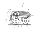
- FIG. 1 is a side external view showing the body posture of a dump truck when it is empty.
- FIG. 2 is a side external view showing the body posture of the dump truck when loaded.
- the dump truck 10 includes a vehicle body 1, left and right front wheels (tires) 2L and 2R, and rear wheels (tires) 3L and 3R, which are the only parts in contact with the road surface, a vehicle body 1 and front and rear left and right wheels 2L.
- 2R, 3L, 3R (2L: left front wheel, 2R: right front wheel, 3L: left rear wheel, 3R: right rear wheel) suspension devices 4L, 4R, 5L, 5R (4L: left front suspension, 4R: right front suspension) 5L: left rear suspension, 5R: right rear suspension), and a vehicle speed sensor 6 installed in the vehicle body 1 so as to radiate electromagnetic waves at a predetermined angle ⁇ with respect to the road surface in the traveling direction.
- the vehicle speed sensor 6 is a sensor that detects the vehicle speed using the Doppler effect, and uses, for example, a millimeter wave radar sensor.
- FIG. 1 illustrates a so-called empty dump 10 in which no load is mounted on the vessel 7.
- the rear load of the dump truck 10 increases, and the vehicle body 1 is centered around the rotation center point 0 and the front of the vehicle body 1 is upward and the rear is downward. Rotate so that the orientation changes.
- This rotational movement amount can be expressed by a rotation angle ⁇ .
- the rotation angle ⁇ is the maximum angle when the load is equivalent to the maximum load capacity of the vessel 7, so-called full load.
- the cylinders of the suspension devices 4L, 4R, 5L, and 5R are subjected to a load of the load 8, so that the pressure increases compared to when the load is empty. Further, the stroke length of each cylinder of the suspension devices 4L, 4R is longer than the stroke length of each cylinder of the suspension devices 5L, 5R.
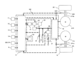
- FIG. 3 is a functional block diagram showing a schematic configuration of the dump drive system.
- the dump truck drive system includes an accelerator pedal 11, a retard pedal 12, a shift lever 13, a combine sensor 14 that senses longitudinal acceleration, lateral acceleration, and yaw rate, and a pressure sensor 15 that measures the pressure in the suspension.
- Engine 21 AC generator 22, other engine load 28, rectifier circuit 23, detection resistor 24, capacitor 25, chopper circuit 26, grid resistor 27, electric motors 31R, 31L, rear wheels 3L, 3R, electric motor 31L , 31R, reduction gears 32L, 32R connected to output shafts 31La, 31Ra, electromagnetic pickup sensors 16L, 16R for measuring the number of rotations of the rear wheels 3L, 3R, and a control device 100.
- the control device 100 includes a controller 41, an inverter control device 42, and a steering control device 43.
- the controller 41 determines the amount of depression from the accelerator pedal 11 and the retard pedal 12, the longitudinal acceleration measured by the combine sensor 14, the lateral acceleration, the yaw rate, and the rotation of the rear wheels 3L and 3R measured by the electromagnetic pickup sensors 16L and 16R. Commands are given to the engine 21, the AC generator 22, the chopper circuit 26, and the inverter control device 42 based on the speed, the current rotational speed of the engine 21 and the moving speed of the vehicle measured by the vehicle speed sensor 6.
- the vehicle moving speed obtained from the rotational speeds of the rear wheels 3L and 3R measured by the electromagnetic pickup sensors 16L and 16R has an error due to tire slip, but the vehicle speed sensor 6 is advantageous in that it is not affected by the tire slip. It is.
- the inverter control device 42 drives each electric motor 31L, 31R based on the moving speed of the vehicle determined from the command from the controller 41 and the rotational speed of the rear wheels 3L, 3R measured by the electromagnetic pickup sensors 16L, 16R.
- FIG. 4 is a functional block diagram showing processing of the vehicle speed device according to the present embodiment.
- the controller 41 calculates a pitching angle that determines a correction angle (pitching angle) for canceling the displacement of the pitching angle of the axle of the dump truck 10 due to the change in the loading state based on the loading state information.
- Part 41a corresponding to a correction angle determination part
- a movement speed correction part 41b for correcting the ground movement speed obtained from the vehicle speed sensor 6, and a correction angle for storing correction angle information defining a correction angle according to the loading state Information storage unit 41c.
- the pitching angle calculation unit 41a, the moving speed correction unit 41b, and the correction angle information storage unit 41c are programs executed by the controller 41 in addition to a calculation / control device such as a CPU (Central Processing Unit) that constitutes the controller 41.
- the above program cooperates with hardware including a storage device such as ROM (Read Only Memory) and HDD (Hard Disk Drive) to store, and RAM (Random Access Memory) as a work area when the CPU executes the program. It is composed by working.
- the pitching angle calculation unit 41a, the movement speed correction unit 41b, and the correction angle information storage unit 41c may be configured by an integrated circuit for realizing these functions.
- the pitching angle calculation unit 41a, the moving speed correction unit 41b, and the correction angle information storage unit 41c are incorporated in the controller 41 mounted on the dump truck 10, but other controllers may be used.
- the pitching angle calculation unit 41a is electrically connected to a pressure sensor 15 (15FL, 15FR, 15RL, 15RR for distinguishing between left front, right front, left rear, and right rear) for measuring the pressure in the suspension.
- the output values of the pressure sensors 15FL, 15FR, 15RL, and 15RR are input to the pitching angle calculation unit 41a.
- Each pressure sensor 15FL, 15FR, 15RL, 15RR corresponds to a loading state information acquisition unit.
- the correction angle information storage unit 41c stores relationship data (corresponding to correction angle information) between cylinder pressure and length in the suspension.
- the relationship data of the pressure in the suspension and the length stored in advance may be changed depending on the temperature of the oil in the suspension or the change with time. In that case, when the vehicle is stopped or running in parallel with the road surface, the radiation angle of the vehicle speed sensor 6 to the road surface is maintained at a predetermined angle ⁇ (hereinafter referred to as a parallel state).
- Calibration may be performed to update the relationship between pressure and length in the suspension. This calibration may be performed when starting the engine or when traveling in a specific section. For dump trucks that reciprocate between two determined points, it is not possible to specify the above calibration section. Is possible.
- This calibration process switches the operation mode of the pitching angle calculation unit 41a to the normal mode (ground movement speed correction mode) or the calibration mode.
- the operation is acquired from each pressure sensor 15FL, 15FR, 15RL, 15RR.
- the stroke length is obtained based on the pressure value, and the elevation angle of the axle is calculated. This can be realized by calculating a correction angle for offsetting the elevation angle and overwriting the relationship data relating the pressure value and the correction angle.
- the operation mode may be switched by an operator of the dump 10 using an operation device (not shown) provided in the dump 10.
- the above relationship data may include data for only two loading states, that is, when the cargo is empty and when it is fully loaded, or may further include data when loading less than the maximum loading capacity.
- data for only two loading states that is, an empty state and a full state
- it may be determined whether there is a change or no load without calculating a specific value of the pressure value.
- the correction angle for the empty state may be 0 ° when there is no change in the pressure value
- the correction angle for the full load state may be ⁇ ° when there is a change in the pressure value.
- the maximum displacement of the pitching angle of the axle caused by the loading state of the transport vehicle is the displacement between the two loading states when empty and full.
- the pitching angle calculation unit 41a collates the pressure value from the pressure sensor 15 with the above relationship data, and estimates the length of each suspension from the pressure value of each suspension. Then, the pitching angle calculation unit 41a obtains the vehicle correction angle ⁇ from the displacement of the suspension length of the front and rear wheels.
- the correction angle ⁇ is calculated using the pressure sensor 15 of the hydraulic / pneumatic suspension apparatus.
- the displacement of the suspension can be reduced by installing the stroke sensor 50 in the front and rear suspensions instead of the pressure sensor 15.
- the correction angle ⁇ may be obtained by detection. Further, calibration can be performed in the same manner as described above.
- the hauling vehicle usually has a suspension, and the cylinder pressure and stroke length of the suspension differ depending on the loaded state of the load. By using this, the correction angle is determined and the existing configuration of the hauling vehicle is utilized. The movement speed can be corrected.
- the transmission wave radiated from the vehicle speed sensor 6 is reflected by the road surface and received again by the vehicle speed sensor 6, but the frequency fr of the reception wave is only the Doppler shift frequency fd due to the Doppler effect when the dump 10 is moving. shift.
- the vehicle speed sensor 6 uses the Doppler shift amount fd to calculate the moving speed V of the vehicle using the following equation.
- V C ⁇ fd / 2 ⁇ ft (2) here,
- C Electromagnetic wave propagation speed (speed of light) It is.
- this moving speed V is the moving speed V in the radial direction of the vehicle speed sensor 6, and the actual moving speed Vc of the vehicle is calculated by the following equation using the radial angle ⁇ of the vehicle speed sensor with respect to the road surface.
- Vc V / cos ⁇ (3)
- the load balance is different between loading and empty loading of the transport vehicle, when a displacement occurs in the pitching angle of the axle, for example, by loading the load on the dump 10 as described above, Even when the front portion of the dump truck 10 is tilted upward, the loading state is determined by determining the correction angle for canceling the displacement and correcting the moving speed of the vehicle speed sensor based on the loading state information. It is possible to detect the more accurate movement speed of the dump truck 10 by reducing the influence of the load balance change caused by the movement on the movement speed.
- the loading state information acquisition unit is configured by a sensor provided in the dump, such as a pressure sensor or a stroke sensor.
- the loading state information acquisition unit can input the loading state information to the controller 41. If there is, it is not limited to the sensor provided in the vehicle body.
- an input device for performing an input operation that the driver is empty or full may be provided.
- a signal indicating an operation of selecting an empty load or a full load performed by the driver on the input device is input to the pitching angle calculation unit 41a.
- the pitching angle calculation unit 41a determines a correction angle ⁇ according to the empty load or full load according to the signal.
- the dump truck when the dump truck is an autonomous traveling vehicle having a traveling control unit that autonomously travels according to an instruction from the operation management server connected through a wireless line, the dump truck is connected to the operation management server via a wireless communication line.
- a communication unit that transmits and receives data is received from the operation management server via the communication unit, and the loading state information indicating whether the dump truck is empty or full is received, and the pitching angle calculation unit 41a receives the loading state information. You may comprise so that it may output.
- the loading state information acquisition unit refers to the map information, the current position of the autonomous traveling vehicle, and the traveling direction of the autonomous traveling vehicle (for example, the traveling direction can be calculated from the displacement of the current position), and from the loading place to the release field It may be configured to determine that the vehicle is fully loaded while traveling toward the vehicle, and that the vehicle is empty when traveling from the earth release site to the loading site.
- the vehicle sensor is provided at the front part of the vehicle body.
- the vehicle sensor may be mounted at a position where the variation in the loading state is smaller than that at the front part of the vehicle body, for example, near the rotation center point.
- suspension displacement due to the presence or absence of the load attention is paid to the suspension displacement due to the presence or absence of the load.
- the suspension displacement due to the influence of the traveling state and the road surface may be used to correct the pitching angle caused by the pitching motion during traveling. .
- the axle is horizontal when empty and the elevation angle ⁇ is oriented when loaded, but if the variation in the stroke of the front wheel cylinder due to the loaded state is greater than the variation in the stroke of the rear wheel cylinder, Sometimes, the axle is designed to be horizontal, and the axle is directed to the elevation angle ⁇ when empty. Even in this case, by using the present invention, the correction angle ( ⁇ ) for canceling the elevation angle ⁇ is obtained and corrected using this to adjust the change in the direction of the axle due to the change in the loading state. be able to.
Landscapes
- Engineering & Computer Science (AREA)
- Radar, Positioning & Navigation (AREA)
- Remote Sensing (AREA)
- Computer Networks & Wireless Communication (AREA)
- Physics & Mathematics (AREA)
- General Physics & Mathematics (AREA)
- Transportation (AREA)
- Mechanical Engineering (AREA)
- Radar Systems Or Details Thereof (AREA)
- Vehicle Body Suspensions (AREA)
Abstract
積載状態の変化により車軸方向の傾きが変動した場合にも車速をより正確に検出することができる運搬車両を提供する。そのために運搬車両10は、電磁波のドップラ効果を利用して対地移動速度を検出する車速センサ6と、運搬車両10の積荷の積載状態を示す積載状態情報を取得する積載状態情報取得部(圧力センサ15)と、積載状態の変動に伴う運搬車両の車軸のピッチング角の変位を相殺するための補正角を、積載状態情報を基に決定する補正角決定部41aと、車速センサ6より得られる移動速度を、補正角を用いて補正する移動速度補正部41bと、を備える。
Description
本発明は運搬車両に係り、特に運搬車両の車速を検出する技術に関する。
運搬車両の車速を検出するために、ドップラ効果を利用した車速センサを用いることが知られている。例えば、特許文献1には、車両に複数の車速センサを設置し、車両の進行方向の速度算出に各車速センサの放射角度を使うことで、ピッチング運動などによる放射角の変動の影響を受けないようにしている。
特許文献1は、走行中のピッチング運動による放射角の変動に対しては補正が行える。しかし、例えば鉱山用ダンプトラックのように積載量が大きい運搬車両は、積荷の積載時と空荷時とを比較すると、積載時は車両の後ろ側に積荷の重量がかかるため、空荷時に比べて車軸のピッチング角度が異なる(仰角方向にシフトする)。そのため、積載時と空荷時とでは、地面に対する放射角が異なるが、特許文献1では積荷の積載状態による放射角の変動については考慮されていない。
本発明は、上記の実情に鑑みてなされたものであり、積載状態の変化により車軸のピッチング角度が変動した場合にも車速をより正確に検出することができる運搬車両を提供することを目的とする。
上記課題を解決するために、本発明に係る運搬車両は、電磁波のドップラ効果を利用して移動速度を検出する車速センサと、運搬車両の積荷の積載状態を示す積載状態情報を取得する積載状態情報取得部と、前記積載状態の変動に伴う前記運搬車両の車軸のピッチング角の変位を相殺するための補正角を、前記積載状態情報を基に決定する補正角決定部と、前記移動速度を、前記補正角を用いて補正する移動速度補正部と、を備えることを特徴とする。
本発明によれば、積載状態の変化により車軸のピッチング角度が変動した場合にも車速をより正確に検出することができる運搬車両を提供することができる。上記した以外の課題、構成及び効果は、以下の実施形態の説明により明らかにされる。
以下、本発明の実施の形態を図面に基づいて詳細に説明する。なお、実施の形態を説明するための全図において、同一の機能を有する部材には同一または関連する符号を付し、その繰り返しの説明は省略する。また、以下の実施の形態では、特に必要なとき以外は同一または同様な部分の説明を原則として繰り返さない。
まず、図1及び図2を参照して本実施形態に係る運搬車両であるダンプトラック(以下「ダンプ」と略記する)の概略構成及び車体姿勢について説明する。図1は、空荷時のダンプの車体姿勢を示す側部外観図である。図2は、積載時のダンプの車体姿勢を示す側部外観図である。
図1において、ダンプ10は、車両本体1、路面と接触する唯一の部分である左右の前輪(タイヤ)2L、2R、及び後輪(タイヤ)3L、3R、車両本体1と前後左右輪2L、2R、3L、3R(2L:左前輪、2R:右前輪、3L:左後輪、3R:右後輪)とを繋ぐサスペンション装置4L、4R、5L、5R(4L:左前サスペンション、4R:右前サスペンション、5L:左後サスペンション、5R:右後サスペンション)、進行方向の路面に対して予め決められた角度θで電磁波を放射するように車両本体1に設置された車速センサ6を備える。車速センサ6は、ドップラ効果を利用して車速を検出するセンサであり、例えばミリ波レーダセンサを用いる。
車体本体1の後方上部には、鉱石や土砂を搭載する荷台(ベッセル)7が搭載される。図1は、ベッセル7に積荷が搭載されていない、所謂空荷の状態のダンプ10を図示している。
図2に示すように、ベッセル7に積荷8を搭載すると、ダンプ10の後方荷重が大きくなり、車両本体1は、回転中心点0を中心に、車両本体1の前方が上方に、後方が下方に向きが変わるよう、回転移動する。この回転移動量は回転角αで表せる。回転角αは、積荷がベッセル7の最大積載量相当のとき、所謂満載時に最大角となる。
ベッセル7に積荷を搭載すると、各サスペンション装置4L、4R、5L、5Rのシリンダは積荷8の荷重が加わったことで空荷時に比べて圧力が増す。また、サスペンション装置4L、4Rの各シリンダのストローク長は、サスペンション装置5L、5Rの各シリンダのストローク長よりも長くなる。
次に図3を参照して、ダンプ10の駆動システムの構成について説明する。図3は、ダンプの駆動システムの概略構成を示す機能ブロック図である。
図3において、ダンプトラックの駆動システムは、アクセルペダル11、リタードペダル12、シフトレバー13、前後加速度と横加速度とヨーレイトをセンシングするコンバインセンサ14、前記サスペンション内の圧力を計測するための圧力センサ15、エンジン21、交流発電機22、その他のエンジン負荷28、整流回路23、検出抵抗24、コンデンサ25、チョッパ回路26、グリッド抵抗27、電動モータ31R,31L、前記後輪3L、3R、電動モータ31L,31Rの出力軸31La,31Raに接続された減速機32L,32R、後輪3L、3Rの回転数を計測するための電磁ピックアップセンサ16L、16R、及び制御装置100を備えている。
制御装置100は、コントローラ41、インバータ制御装置42、操舵制御装置43から成る。
コントローラ41は、アクセルペダル11、リタードペダル12からの踏込み量、コンバインセンサ14にて計測される前後加速度、横加速度、ヨーレイト、電磁ピックアップセンサ16L、16Rにて計測される後輪3L、3Rの回転速度、エンジン21の現回転数及び車速センサ6にて計測される車両の移動速度を基に、エンジン21、交流発電機22、チョッパ回路26、インバータ制御装置42に指令を与える。
なお、電磁ピックアップセンサ16L、16Rにて計測される後輪3L、3Rの回転速度から求まる車両の移動速度はタイヤスリップにより誤差が生じるが、車速センサ6はタイヤスリップによる影響は受けない点で有利である。
インバータ制御装置42は、コントローラ41からの指令と電磁ピックアップセンサ16L、16Rにて計測される後輪3L、3Rの回転速度から求まる車両の移動速度を基に各電動モータ31L、31Rを駆動させる。
〔処理・動作例〕
図4を参照して、車速計測装置の処理を説明する。図4は、本実施形態に係る車速装置の処理を示す機能ブロック図である。
図4を参照して、車速計測装置の処理を説明する。図4は、本実施形態に係る車速装置の処理を示す機能ブロック図である。
図4に示すように、コントローラ41は、積載状態の変動に伴うダンプ10の車軸のピッチング角の変位を相殺するための補正角(ピッチング角)を、積載状態情報を基に決定するピッチング角算出部41a(補正角決定部に相当する)と、車速センサ6より得られる対地移動速度を補正する移動速度補正部41bと、積載状態に応じた補正角を規定した補正角情報を記憶する補正角情報記憶部41cと、を含む。
これらピッチング角算出部41a、移動速度補正部41b、及び補正角情報記憶部41cは、コントローラ41を構成するCPU(Central Processing Unit)等の演算・制御装置の他、コントローラ41で実行されるプログラムを格納するROM(Read Only Memory)やHDD(Hard Disk Drive)等の記憶装置、また、CPUがプログラムを実行する際の作業領域となるRAM(Random Access Memory)を含むハードウェアと上記プログラムとが協働することにより構成される。また、ピッチング角算出部41a、移動速度補正部41b、及び補正角情報記憶部41cは、これらの機能を実現するための集積回路により構成されてもよい。ピッチング角算出部41a、移動速度補正部41b、及び補正角情報記憶部41cは、ダンプ10に搭載されているコントローラ41内に組み込んでいるが、別のコントローラを用いても良い。
ピッチング角算出部41aは、サスペンション内の圧力を計測するための圧力センサ15(左前、右前、左後、右後を区別するため、15FL、15FR、15RL、15RRとする)と電気的に接続され、各圧力センサ15FL、15FR、15RL、15RRの出力値がピッチング角算出部41aに入力される。各圧力センサ15FL、15FR、15RL、15RRは、積載状態情報取得部に相当する。
補正角情報記憶部41cは、サスペンション内のシリンダ圧力と長さの関係性データ(補正角情報に相当する)を記憶する。なお、サスペンション内の油の温度や経時変化などにより予め記憶されているサスペンション内の圧力と長さの関係性データが変化する事がある。その場合は、車両が路面に対して平行に停止もしくは走行しており、車速センサ6の路面への放射角が予め決められた角度θが保たれたままとなっている時(以後、平行状態という)にキャリブレーションを行い、サスペンション内の圧力と長さの関係性データを更新するようにしてもよい。このキャリブレーションはエンジン始動時や特定の区間を走行している時などに実施すればよく、決められた2地点間を往復するような用途のダンプトラックでは上記のキャリブレーション区間を特定することは可能である。
このキャリブレーション処理は、ピッチング角算出部41aの動作モードを、通常モード(対地移動速度の補正モード)又はキャリブレーションモードに切り替え、キャリブレーションモードでは、各圧力センサ15FL、15FR、15RL、15RRから取得した圧力値を基にストローク長を求め、車軸の仰角を算出する。そしてこの仰角をオフセットするための補正角を算出し、上記の圧力値と補正角とを関係付けた関係性データに上書きするように動作させることで実現できる。なお、動作モードの切替は、ダンプ10内に備えられた不図示の操作装置により、ダンプ10のオペレータが行うように構成してもよい。
上記関係性データは、空荷時と満載時との二つの積載状態だけのデータを保有してもよいし、最大積載量未満の積載時のデータを更に保有するようにしてもよい。空荷時と満載時との二つの積載状態だけのデータを備える場合は、圧力値の具体的な値を算出することなく、変化の有無で空荷時又は満載時を判定してもよい。この場合の補正角は、圧力値の変化がない場合は空荷状態に対する補正角を0°、圧力値の変化があった場合は満載状態に対する補正角をα°としてもよい。これにより、運搬車両の積載状態に起因する車軸のピッチング角の変位が最大となるのは、空荷時及び満載時の二つの積載状態の間における変位であるので、これら二つの状態間の変動幅を吸収することで、積載状態が対地移動速度に与える影響をより低減することができる。
ピッチング角算出部41aは、圧力センサ15からの圧力値を上記関係性データと照合し、各サスペンションの圧力値から各サスペンションの長さを推定する。そして、ピッチング角算出部41aは、前後輪のサスペンションの長さの変位から車両の補正角αを求める。
本実施形態では、油空圧サスペンション装置の圧力センサ15を用いて補正角αを算出する例を示したが、圧力センサ15に代えて前後サスペンションにストロークセンサ50を設置することでサスペンションの変位を検出し、補正角αを求めても良い。また、キャリブレーションに関しても前記同様に実施可能である。
運搬車両は通常サスペンションを搭載しており、積荷の積載状態に応じてサスペンションのシリンダ圧力及びストローク長が異なることから、これを用いて補正角を決定することにより、運搬車両の既存の構成を活用して移動速度の補正が行える。
次に、移動速度補正部41bについて説明する。
車速センサ6から放射された送信波は、路面にて反射し再び車速センサ6にて受信されるが、受信波の周波数frはダンプ10が移動していた場合、ドップラ効果によりドップラシフト周波数fdだけシフトする。すなわち、送信波の周波数ft、受信波の周波数fr、ドップラシフト量fdには以下の関係となる。
fr=ft+fd…(1)
fr=ft+fd…(1)
車速センサ6はこのドップラシフト量fdを使って、車両の移動速度Vを以下の式にて算出する。
V=C・fd/2・ft…(2)
ここで、
C:電磁波伝搬速度(光速)
である。
V=C・fd/2・ft…(2)
ここで、
C:電磁波伝搬速度(光速)
である。
しかしながら、この移動速度Vは車速センサ6の放射方向に対する移動速度Vであり、実際の車両の移動速度Vcは、路面に対する車速センサの放射角度θを用いて、以下の式で算出される。
Vc=V/cosθ…(3)
Vc=V/cosθ…(3)
(3)式から分かるように、ダンプ10自体のピッチング運動や積荷の影響により路面に対する車速センサ6の放射角θが変わってしまうと正確な移動速度Vcを求めることができない。
移動速度補正部41bでは、平行状態時の放射角θからピッチング角算出部41aで算出された補正角αを引くことで、積載状態の違いに起因する放射角の変動を吸収して正確な放射角を求め、それを基に移動速度Vcを算出する。
Vc=V/cos(θ-α)…(4)
Vc=V/cos(θ-α)…(4)
本実施形態によれば、運搬車両の積載時と空荷時とでは荷重バランスが異なるため、車軸のピッチング角度に変位が生じた場合、例えば上記のようにダンプ10に積荷を積載したことにより、ダンプ10の前部が上方を向くように傾いた場合にも、積載状態情報を基に、その変位を相殺するための補正角を決定して車速センサの移動速度を補正することにより、積載状態に起因する荷重バランスの変化の影響が移動速度に及ぼす影響を減らしてより正確なダンプ10の対地移動速度を検出することができる。
以上、本発明の実施の形態を説明したが、本発明は上述の実施の形態に限定されず、発明の要旨を逸脱しない範囲の設計変更等があっても本発明に含まれる。
例えば、上記実施の形態では、ダンプトラックに本発明を適用した場合について説明したが、ホイールローダ等の他の作業機械もしくは一般的な乗用車などに適用しても同様の効果が得られる。
また、本実施形態では、積載状態情報取得部をダンプに備えられたセンサ、例えば圧力センサやストロークセンサにより構成したが、積載状態情報取得部はコントローラ41に対して積載状態情報を入力できる構成であれば車体に設けられたセンサには限定されない。
例えば、運転手が搭乗して操舵するダンプトラック、所謂有人ダンプの場合、運転手が空荷又は満載であることを入力操作する入力装置を備えてもよい。この場合、運転手がこの入力装置に対して行った空荷又は満載を選択する操作を示す信号が、ピッチング角度算出部41aに入力される。ピッチング角度算出部41aはその信号に従って、空荷又は満載に応じた補正角αを決定する。
また、ダンプトラックが、無線回線を通じて接続された運行管理サーバからの指示に従って自律走行する走行制御部を備えた自律走行運搬車両である場合は、運行管理サーバとの間で無線通信回線を介してデータの送受信を行う通信部を備え、その通信部を介してダンプトラックが空荷又は満載のいずれかの状態であるかを示す積載状態情報を運行管理サーバから受信し、ピッチング角度算出部41aに出力するように構成してもよい。
また、自律走行運搬車両は、積込場及び放土場を連結する、予め決められた走行路を走行するので、この走行路を示す地図情報を記憶する地図情報記憶部と、自律走行車両の現在位置を算出する位置算出装置とを有することが多い。そこで、積載状態情報取得部は、地図情報、自律走行車両の現在位置及び自律走行運搬車両の走行方向(例えば現在位置の変位から走行方向は算出できる)を参照し、積込場から放土場に向けて走行中は満載、放土場から積込場に走行中は空荷と判定するように構成されてもよい。
また、本実施形態では車両センサを車体本体の前部に備えたが、車両本体の前部よりもより積載状態の変動がより少ない位置、例えば回転中心点付近に搭載してもよい。
また、本実施形態では、積荷の有無によるサスペンション変位に着目したが、これだけではなく、走行状態や路面の影響によるサスペンション変位も用いて、走行中ピッチング運動により生じるピッチング角の補正も行ってもよい。
また上記では、空荷時に車軸が水平、積載時に車軸が仰角αを向くとして説明したが、積載状態に伴う前輪側シリンダーのストローク変動が、後輪側シリンダーのストローク変動よりも大きい場合は、積載時に車軸が水平になるように設計し、空荷時に車軸が仰角αを向く場合もある。この場合でも、本発明を用いることで、仰角αを相殺するための補正角(-α)を求め、これを用いて補正することで、積載状態の変動に伴う車軸の向きの変動を調整することができる。
1 車両本体
2R、2L 前輪
3R、3L 後輪
4R、4L 前サスペンション装置
5R、5L 後サスペンション装置
6 車速センサ
11 アクセルペダル
12 リタードペダル
13 シフトレバー
14 コンバインセンサ
15 サスペンション圧力センサ
15FL、15FR、15RL、15RR 前後左右サスペンション圧力センサ
16L,16R 電磁ピックアップセンサ
21 エンジン
22 交流発電機
50 ストロークセンサ
2R、2L 前輪
3R、3L 後輪
4R、4L 前サスペンション装置
5R、5L 後サスペンション装置
6 車速センサ
11 アクセルペダル
12 リタードペダル
13 シフトレバー
14 コンバインセンサ
15 サスペンション圧力センサ
15FL、15FR、15RL、15RR 前後左右サスペンション圧力センサ
16L,16R 電磁ピックアップセンサ
21 エンジン
22 交流発電機
50 ストロークセンサ
Claims (3)
- 電磁波のドップラ効果を利用して移動速度を検出する車速センサ(6)と、
運搬車両(10)の積荷の積載状態を示す積載状態情報を取得する積載状態情報取得部(15)と、
前記積載状態の変動に伴う前記運搬車両の車軸のピッチング角の変位を相殺するための補正角を、前記積載状態情報を基に決定する補正角決定部(41a)と、
前記移動速度を、前記補正角を用いて補正する移動速度補正部(41b)と、
を備えることを特徴とする運搬車両。 - 前記積載状態情報取得部(15)は、前記運搬車両(10)に搭載されたサスペンションのシリンダ圧力を検出する圧力センサ(15)、又は前記サスペンションのストローク長を検出するストロークセンサ(50)であって、
前記補正角決定部は、前記圧力センサ又は前記ストロークセンサの出力値を基に前記補正角を決定する、
ことを特徴とする請求項1に記載の運搬車両。 - 前記運搬車両の空荷時の補正角、又は前記運搬車両の最大積載量に相当する積荷を積載した満載時の補正角を規定した補正角情報を記憶する補正角情報記憶部(41c)を更に備え、
前記積載状態情報取得部(15)は、前記運搬車両(10)が空荷又は満載のいずれかの状態であることを示す前記積載状態情報を取得し、
前記補正角決定部(41b)は、前記積載状態情報が示す積載状態に対応した補正角を、前記補正角情報を基に決定する、
ことを特徴する請求項1に記載の運搬車両。
Applications Claiming Priority (2)
| Application Number | Priority Date | Filing Date | Title |
|---|---|---|---|
| JP2014-149184 | 2014-07-22 | ||
| JP2014149184A JP2016024097A (ja) | 2014-07-22 | 2014-07-22 | 運搬車両 |
Publications (1)
| Publication Number | Publication Date |
|---|---|
| WO2016013372A1 true WO2016013372A1 (ja) | 2016-01-28 |
Family
ID=55162904
Family Applications (1)
| Application Number | Title | Priority Date | Filing Date |
|---|---|---|---|
| PCT/JP2015/069164 Ceased WO2016013372A1 (ja) | 2014-07-22 | 2015-07-02 | 運搬車両 |
Country Status (2)
| Country | Link |
|---|---|
| JP (1) | JP2016024097A (ja) |
| WO (1) | WO2016013372A1 (ja) |
Cited By (2)
| Publication number | Priority date | Publication date | Assignee | Title |
|---|---|---|---|---|
| CN109405888A (zh) * | 2018-12-10 | 2019-03-01 | 大连奥雷科技有限公司 | 工程车运输状态监测装置及方法 |
| US20230221121A1 (en) * | 2020-04-22 | 2023-07-13 | Jfe Steel Corporation | Heavy goods vehicle |
Families Citing this family (2)
| Publication number | Priority date | Publication date | Assignee | Title |
|---|---|---|---|---|
| US10935670B2 (en) * | 2018-03-28 | 2021-03-02 | Psionic, Llc | Navigation system for GPS denied environments |
| CN118907147B (zh) * | 2024-10-10 | 2025-02-14 | 临沂临工金利机械有限公司 | 一种无人驾驶室矿用自卸车自动作业系统及方法 |
Citations (6)
| Publication number | Priority date | Publication date | Assignee | Title |
|---|---|---|---|---|
| JPS4988570A (ja) * | 1972-12-23 | 1974-08-23 | ||
| JPS51113676A (en) * | 1975-03-28 | 1976-10-06 | Komatsu Ltd | Speed detector |
| JPH0540173A (ja) * | 1991-08-05 | 1993-02-19 | Toyota Motor Corp | ドツプラ式対地車速検出装置 |
| JPH07104066A (ja) * | 1993-10-01 | 1995-04-21 | Mazda Motor Corp | 車両の障害物検知装置 |
| JPH1114746A (ja) * | 1997-06-25 | 1999-01-22 | Honda Motor Co Ltd | 車両の障害物検知装置 |
| JP2010142058A (ja) * | 2008-12-15 | 2010-06-24 | Hitachi Constr Mach Co Ltd | 電動車両及びそのピッチング制御装置 |
-
2014
- 2014-07-22 JP JP2014149184A patent/JP2016024097A/ja active Pending
-
2015
- 2015-07-02 WO PCT/JP2015/069164 patent/WO2016013372A1/ja not_active Ceased
Patent Citations (6)
| Publication number | Priority date | Publication date | Assignee | Title |
|---|---|---|---|---|
| JPS4988570A (ja) * | 1972-12-23 | 1974-08-23 | ||
| JPS51113676A (en) * | 1975-03-28 | 1976-10-06 | Komatsu Ltd | Speed detector |
| JPH0540173A (ja) * | 1991-08-05 | 1993-02-19 | Toyota Motor Corp | ドツプラ式対地車速検出装置 |
| JPH07104066A (ja) * | 1993-10-01 | 1995-04-21 | Mazda Motor Corp | 車両の障害物検知装置 |
| JPH1114746A (ja) * | 1997-06-25 | 1999-01-22 | Honda Motor Co Ltd | 車両の障害物検知装置 |
| JP2010142058A (ja) * | 2008-12-15 | 2010-06-24 | Hitachi Constr Mach Co Ltd | 電動車両及びそのピッチング制御装置 |
Cited By (3)
| Publication number | Priority date | Publication date | Assignee | Title |
|---|---|---|---|---|
| CN109405888A (zh) * | 2018-12-10 | 2019-03-01 | 大连奥雷科技有限公司 | 工程车运输状态监测装置及方法 |
| US20230221121A1 (en) * | 2020-04-22 | 2023-07-13 | Jfe Steel Corporation | Heavy goods vehicle |
| US12339121B2 (en) * | 2020-04-22 | 2025-06-24 | Jfe Steel Corporation | Heavy goods vehicle |
Also Published As
| Publication number | Publication date |
|---|---|
| JP2016024097A (ja) | 2016-02-08 |
Similar Documents
| Publication | Publication Date | Title |
|---|---|---|
| US11235747B2 (en) | Method for controlling a steering system of a vehicle | |
| US10343717B2 (en) | Travel vehicle and method for controlling travel vehicle | |
| JP5171594B2 (ja) | 電動車両及びそのピッチング制御装置 | |
| US8219282B2 (en) | System for dynamically determining vehicle rear/trunk loading for use in a vehicle control system | |
| CN102482066B (zh) | 具有高度可调节的升降装置的载货汽车 | |
| US8831854B2 (en) | Active shimmy mitigation | |
| JP6386412B2 (ja) | 運搬車両 | |
| US9169110B2 (en) | Method for determining the probability of a handling truck's tipping over | |
| US20190263458A1 (en) | Methods and systems for active aerodynamic balance | |
| US8983722B2 (en) | System and method for vehicle rollover prediction | |
| US20050288842A1 (en) | Method and apparatus for determining a reference vehicle velocity and a rear wheel speed in a vehicle having three speed sensors | |
| JP7354272B2 (ja) | 車両操作中の車両運動状態を推定する方法 | |
| JP6247904B2 (ja) | 鉱山用運搬車両 | |
| JP2012126293A (ja) | 車両の操舵制御装置 | |
| JP2016024097A (ja) | 運搬車両 | |
| US11453437B2 (en) | Control device and steering device | |
| US20210053617A1 (en) | Control device and steering device | |
| JP5487252B2 (ja) | 電動車両及びそのピッチング制御装置 | |
| US12589733B2 (en) | Determination apparatus of center of gravity position, and determination method thereof | |
| KR20150128046A (ko) | 지능형타이어센서를 이용한 차량 휠 제어 시스템 및 그 방법 | |
| JP2013129284A (ja) | ピッチング角処理装置 | |
| CN107444487B (zh) | 用于可变转向辅助的系统和方法-ii | |
| JP2008154346A (ja) | 車両姿勢制御装置及び走行装置 | |
| JP6970043B2 (ja) | 車両安定制御装置 | |
| JP7279588B2 (ja) | 車両用挙動制御装置 |
Legal Events
| Date | Code | Title | Description |
|---|---|---|---|
| 121 | Ep: the epo has been informed by wipo that ep was designated in this application |
Ref document number: 15825432 Country of ref document: EP Kind code of ref document: A1 |
|
| NENP | Non-entry into the national phase |
Ref country code: DE |
|
| 32PN | Ep: public notification in the ep bulletin as address of the adressee cannot be established |
Free format text: NOTING OF LOSS OF RIGHTS PURSUANT TO RULE 112(1) EPC (EPO FORM 1205A DATED 28.04.2017) |
|
| 122 | Ep: pct application non-entry in european phase |
Ref document number: 15825432 Country of ref document: EP Kind code of ref document: A1 |