WO2016013194A1 - 冷凍サイクル装置 - Google Patents
冷凍サイクル装置 Download PDFInfo
- Publication number
- WO2016013194A1 WO2016013194A1 PCT/JP2015/003617 JP2015003617W WO2016013194A1 WO 2016013194 A1 WO2016013194 A1 WO 2016013194A1 JP 2015003617 W JP2015003617 W JP 2015003617W WO 2016013194 A1 WO2016013194 A1 WO 2016013194A1
- Authority
- WO
- WIPO (PCT)
- Prior art keywords
- refrigeration cycle
- circuit
- heat exchanger
- cooling water
- water
- Prior art date
Links
Images


Classifications
-
- B—PERFORMING OPERATIONS; TRANSPORTING
- B60—VEHICLES IN GENERAL
- B60H—ARRANGEMENTS OF HEATING, COOLING, VENTILATING OR OTHER AIR-TREATING DEVICES SPECIALLY ADAPTED FOR PASSENGER OR GOODS SPACES OF VEHICLES
- B60H1/00—Heating, cooling or ventilating [HVAC] devices
- B60H1/00642—Control systems or circuits; Control members or indication devices for heating, cooling or ventilating devices
- B60H1/00814—Control systems or circuits characterised by their output, for controlling particular components of the heating, cooling or ventilating installation
- B60H1/00878—Control systems or circuits characterised by their output, for controlling particular components of the heating, cooling or ventilating installation the components being temperature regulating devices
- B60H1/00899—Controlling the flow of liquid in a heat pump system
- B60H1/00921—Controlling the flow of liquid in a heat pump system where the flow direction of the refrigerant does not change and there is an extra subcondenser, e.g. in an air duct
-
- B—PERFORMING OPERATIONS; TRANSPORTING
- B60—VEHICLES IN GENERAL
- B60H—ARRANGEMENTS OF HEATING, COOLING, VENTILATING OR OTHER AIR-TREATING DEVICES SPECIALLY ADAPTED FOR PASSENGER OR GOODS SPACES OF VEHICLES
- B60H1/00—Heating, cooling or ventilating [HVAC] devices
- B60H1/32—Cooling devices
- B60H1/3204—Cooling devices using compression
- B60H1/3228—Cooling devices using compression characterised by refrigerant circuit configurations
-
- B—PERFORMING OPERATIONS; TRANSPORTING
- B60—VEHICLES IN GENERAL
- B60H—ARRANGEMENTS OF HEATING, COOLING, VENTILATING OR OTHER AIR-TREATING DEVICES SPECIALLY ADAPTED FOR PASSENGER OR GOODS SPACES OF VEHICLES
- B60H1/00—Heating, cooling or ventilating [HVAC] devices
- B60H1/32—Cooling devices
- B60H1/3204—Cooling devices using compression
- B60H1/323—Cooling devices using compression characterised by comprising auxiliary or multiple systems, e.g. plurality of evaporators, or by involving auxiliary cooling devices
-
- F—MECHANICAL ENGINEERING; LIGHTING; HEATING; WEAPONS; BLASTING
- F25—REFRIGERATION OR COOLING; COMBINED HEATING AND REFRIGERATION SYSTEMS; HEAT PUMP SYSTEMS; MANUFACTURE OR STORAGE OF ICE; LIQUEFACTION SOLIDIFICATION OF GASES
- F25B—REFRIGERATION MACHINES, PLANTS OR SYSTEMS; COMBINED HEATING AND REFRIGERATION SYSTEMS; HEAT PUMP SYSTEMS
- F25B27/00—Machines, plants or systems, using particular sources of energy
- F25B27/02—Machines, plants or systems, using particular sources of energy using waste heat, e.g. from internal-combustion engines
-
- F—MECHANICAL ENGINEERING; LIGHTING; HEATING; WEAPONS; BLASTING
- F25—REFRIGERATION OR COOLING; COMBINED HEATING AND REFRIGERATION SYSTEMS; HEAT PUMP SYSTEMS; MANUFACTURE OR STORAGE OF ICE; LIQUEFACTION SOLIDIFICATION OF GASES
- F25B—REFRIGERATION MACHINES, PLANTS OR SYSTEMS; COMBINED HEATING AND REFRIGERATION SYSTEMS; HEAT PUMP SYSTEMS
- F25B41/00—Fluid-circulation arrangements
- F25B41/40—Fluid line arrangements
- F25B41/42—Arrangements for diverging or converging flows, e.g. branch lines or junctions
-
- F—MECHANICAL ENGINEERING; LIGHTING; HEATING; WEAPONS; BLASTING
- F25—REFRIGERATION OR COOLING; COMBINED HEATING AND REFRIGERATION SYSTEMS; HEAT PUMP SYSTEMS; MANUFACTURE OR STORAGE OF ICE; LIQUEFACTION SOLIDIFICATION OF GASES
- F25B—REFRIGERATION MACHINES, PLANTS OR SYSTEMS; COMBINED HEATING AND REFRIGERATION SYSTEMS; HEAT PUMP SYSTEMS
- F25B47/00—Arrangements for preventing or removing deposits or corrosion, not provided for in another subclass
- F25B47/02—Defrosting cycles
- F25B47/022—Defrosting cycles hot gas defrosting
-
- F—MECHANICAL ENGINEERING; LIGHTING; HEATING; WEAPONS; BLASTING
- F25—REFRIGERATION OR COOLING; COMBINED HEATING AND REFRIGERATION SYSTEMS; HEAT PUMP SYSTEMS; MANUFACTURE OR STORAGE OF ICE; LIQUEFACTION SOLIDIFICATION OF GASES
- F25B—REFRIGERATION MACHINES, PLANTS OR SYSTEMS; COMBINED HEATING AND REFRIGERATION SYSTEMS; HEAT PUMP SYSTEMS
- F25B49/00—Arrangement or mounting of control or safety devices
- F25B49/02—Arrangement or mounting of control or safety devices for compression type machines, plants or systems
-
- B—PERFORMING OPERATIONS; TRANSPORTING
- B60—VEHICLES IN GENERAL
- B60H—ARRANGEMENTS OF HEATING, COOLING, VENTILATING OR OTHER AIR-TREATING DEVICES SPECIALLY ADAPTED FOR PASSENGER OR GOODS SPACES OF VEHICLES
- B60H1/00—Heating, cooling or ventilating [HVAC] devices
- B60H1/00642—Control systems or circuits; Control members or indication devices for heating, cooling or ventilating devices
- B60H1/00814—Control systems or circuits characterised by their output, for controlling particular components of the heating, cooling or ventilating installation
- B60H1/00878—Control systems or circuits characterised by their output, for controlling particular components of the heating, cooling or ventilating installation the components being temperature regulating devices
- B60H2001/00961—Control systems or circuits characterised by their output, for controlling particular components of the heating, cooling or ventilating installation the components being temperature regulating devices comprising means for defrosting outside heat exchangers
-
- F—MECHANICAL ENGINEERING; LIGHTING; HEATING; WEAPONS; BLASTING
- F25—REFRIGERATION OR COOLING; COMBINED HEATING AND REFRIGERATION SYSTEMS; HEAT PUMP SYSTEMS; MANUFACTURE OR STORAGE OF ICE; LIQUEFACTION SOLIDIFICATION OF GASES
- F25B—REFRIGERATION MACHINES, PLANTS OR SYSTEMS; COMBINED HEATING AND REFRIGERATION SYSTEMS; HEAT PUMP SYSTEMS
- F25B2339/00—Details of evaporators; Details of condensers
- F25B2339/04—Details of condensers
- F25B2339/047—Water-cooled condensers
-
- F—MECHANICAL ENGINEERING; LIGHTING; HEATING; WEAPONS; BLASTING
- F25—REFRIGERATION OR COOLING; COMBINED HEATING AND REFRIGERATION SYSTEMS; HEAT PUMP SYSTEMS; MANUFACTURE OR STORAGE OF ICE; LIQUEFACTION SOLIDIFICATION OF GASES
- F25B—REFRIGERATION MACHINES, PLANTS OR SYSTEMS; COMBINED HEATING AND REFRIGERATION SYSTEMS; HEAT PUMP SYSTEMS
- F25B2400/00—General features or devices for refrigeration machines, plants or systems, combined heating and refrigeration systems or heat-pump systems, i.e. not limited to a particular subgroup of F25B
- F25B2400/04—Refrigeration circuit bypassing means
- F25B2400/0401—Refrigeration circuit bypassing means for the compressor
-
- F—MECHANICAL ENGINEERING; LIGHTING; HEATING; WEAPONS; BLASTING
- F25—REFRIGERATION OR COOLING; COMBINED HEATING AND REFRIGERATION SYSTEMS; HEAT PUMP SYSTEMS; MANUFACTURE OR STORAGE OF ICE; LIQUEFACTION SOLIDIFICATION OF GASES
- F25B—REFRIGERATION MACHINES, PLANTS OR SYSTEMS; COMBINED HEATING AND REFRIGERATION SYSTEMS; HEAT PUMP SYSTEMS
- F25B2400/00—General features or devices for refrigeration machines, plants or systems, combined heating and refrigeration systems or heat-pump systems, i.e. not limited to a particular subgroup of F25B
- F25B2400/04—Refrigeration circuit bypassing means
- F25B2400/0403—Refrigeration circuit bypassing means for the condenser
-
- F—MECHANICAL ENGINEERING; LIGHTING; HEATING; WEAPONS; BLASTING
- F25—REFRIGERATION OR COOLING; COMBINED HEATING AND REFRIGERATION SYSTEMS; HEAT PUMP SYSTEMS; MANUFACTURE OR STORAGE OF ICE; LIQUEFACTION SOLIDIFICATION OF GASES
- F25B—REFRIGERATION MACHINES, PLANTS OR SYSTEMS; COMBINED HEATING AND REFRIGERATION SYSTEMS; HEAT PUMP SYSTEMS
- F25B2400/00—General features or devices for refrigeration machines, plants or systems, combined heating and refrigeration systems or heat-pump systems, i.e. not limited to a particular subgroup of F25B
- F25B2400/04—Refrigeration circuit bypassing means
- F25B2400/0409—Refrigeration circuit bypassing means for the evaporator
-
- F—MECHANICAL ENGINEERING; LIGHTING; HEATING; WEAPONS; BLASTING
- F25—REFRIGERATION OR COOLING; COMBINED HEATING AND REFRIGERATION SYSTEMS; HEAT PUMP SYSTEMS; MANUFACTURE OR STORAGE OF ICE; LIQUEFACTION SOLIDIFICATION OF GASES
- F25B—REFRIGERATION MACHINES, PLANTS OR SYSTEMS; COMBINED HEATING AND REFRIGERATION SYSTEMS; HEAT PUMP SYSTEMS
- F25B2400/00—General features or devices for refrigeration machines, plants or systems, combined heating and refrigeration systems or heat-pump systems, i.e. not limited to a particular subgroup of F25B
- F25B2400/04—Refrigeration circuit bypassing means
- F25B2400/0411—Refrigeration circuit bypassing means for the expansion valve or capillary tube
-
- F—MECHANICAL ENGINEERING; LIGHTING; HEATING; WEAPONS; BLASTING
- F25—REFRIGERATION OR COOLING; COMBINED HEATING AND REFRIGERATION SYSTEMS; HEAT PUMP SYSTEMS; MANUFACTURE OR STORAGE OF ICE; LIQUEFACTION SOLIDIFICATION OF GASES
- F25B—REFRIGERATION MACHINES, PLANTS OR SYSTEMS; COMBINED HEATING AND REFRIGERATION SYSTEMS; HEAT PUMP SYSTEMS
- F25B2600/00—Control issues
- F25B2600/25—Control of valves
- F25B2600/2513—Expansion valves
-
- F—MECHANICAL ENGINEERING; LIGHTING; HEATING; WEAPONS; BLASTING
- F25—REFRIGERATION OR COOLING; COMBINED HEATING AND REFRIGERATION SYSTEMS; HEAT PUMP SYSTEMS; MANUFACTURE OR STORAGE OF ICE; LIQUEFACTION SOLIDIFICATION OF GASES
- F25B—REFRIGERATION MACHINES, PLANTS OR SYSTEMS; COMBINED HEATING AND REFRIGERATION SYSTEMS; HEAT PUMP SYSTEMS
- F25B2600/00—Control issues
- F25B2600/25—Control of valves
- F25B2600/2519—On-off valves
-
- F—MECHANICAL ENGINEERING; LIGHTING; HEATING; WEAPONS; BLASTING
- F25—REFRIGERATION OR COOLING; COMBINED HEATING AND REFRIGERATION SYSTEMS; HEAT PUMP SYSTEMS; MANUFACTURE OR STORAGE OF ICE; LIQUEFACTION SOLIDIFICATION OF GASES
- F25B—REFRIGERATION MACHINES, PLANTS OR SYSTEMS; COMBINED HEATING AND REFRIGERATION SYSTEMS; HEAT PUMP SYSTEMS
- F25B2700/00—Sensing or detecting of parameters; Sensors therefor
- F25B2700/21—Temperatures
- F25B2700/2115—Temperatures of a compressor or the drive means therefor
- F25B2700/21152—Temperatures of a compressor or the drive means therefor at the discharge side of the compressor
-
- F—MECHANICAL ENGINEERING; LIGHTING; HEATING; WEAPONS; BLASTING
- F25—REFRIGERATION OR COOLING; COMBINED HEATING AND REFRIGERATION SYSTEMS; HEAT PUMP SYSTEMS; MANUFACTURE OR STORAGE OF ICE; LIQUEFACTION SOLIDIFICATION OF GASES
- F25B—REFRIGERATION MACHINES, PLANTS OR SYSTEMS; COMBINED HEATING AND REFRIGERATION SYSTEMS; HEAT PUMP SYSTEMS
- F25B2700/00—Sensing or detecting of parameters; Sensors therefor
- F25B2700/21—Temperatures
- F25B2700/2116—Temperatures of a condenser
- F25B2700/21162—Temperatures of a condenser of the refrigerant at the inlet of the condenser
-
- F—MECHANICAL ENGINEERING; LIGHTING; HEATING; WEAPONS; BLASTING
- F25—REFRIGERATION OR COOLING; COMBINED HEATING AND REFRIGERATION SYSTEMS; HEAT PUMP SYSTEMS; MANUFACTURE OR STORAGE OF ICE; LIQUEFACTION SOLIDIFICATION OF GASES
- F25B—REFRIGERATION MACHINES, PLANTS OR SYSTEMS; COMBINED HEATING AND REFRIGERATION SYSTEMS; HEAT PUMP SYSTEMS
- F25B2700/00—Sensing or detecting of parameters; Sensors therefor
- F25B2700/21—Temperatures
- F25B2700/2117—Temperatures of an evaporator
-
- Y—GENERAL TAGGING OF NEW TECHNOLOGICAL DEVELOPMENTS; GENERAL TAGGING OF CROSS-SECTIONAL TECHNOLOGIES SPANNING OVER SEVERAL SECTIONS OF THE IPC; TECHNICAL SUBJECTS COVERED BY FORMER USPC CROSS-REFERENCE ART COLLECTIONS [XRACs] AND DIGESTS
- Y02—TECHNOLOGIES OR APPLICATIONS FOR MITIGATION OR ADAPTATION AGAINST CLIMATE CHANGE
- Y02A—TECHNOLOGIES FOR ADAPTATION TO CLIMATE CHANGE
- Y02A30/00—Adapting or protecting infrastructure or their operation
- Y02A30/27—Relating to heating, ventilation or air conditioning [HVAC] technologies
- Y02A30/274—Relating to heating, ventilation or air conditioning [HVAC] technologies using waste energy, e.g. from internal combustion engine
Definitions
- the present disclosure has a refrigeration cycle circuit and a plurality of water refrigerant heat exchangers constituting a plurality of heat pumps, transfers heat absorbed from the air by one heat pump to the other heat pump side via the hot water circuit,
- the present invention relates to a refrigeration cycle apparatus that can be used for defrosting operation.
- Patent Document 1 as a conventional technique discloses a device having a plurality of refrigeration cycle circuits.
- the purpose of this device is to provide a heat pump device that can defrost while continuing the supply of heat, and can suppress fluctuations in the amount of heat supply even if defrosting is performed. For this reason, when one refrigeration cycle circuit performs a defrosting operation, the other one refrigeration cycle circuit provides a heat pump device that can increase the amount of heat supplied.
- the heat of the plurality of refrigeration cycle circuits and the heat of the hot water circuit cannot be effectively used, and the defrosting time may be relatively long.
- the present disclosure uses heat absorbed by the first refrigeration cycle circuit for defrosting the second refrigeration cycle circuit via the hot water circuit. Then, it aims at improving defrost efficiency and aiming at shortening of defrost time.
- a first refrigeration cycle circuit a second refrigeration cycle circuit, a heat source cooling water circuit having a heater core that cools the heat source and warms the conditioned air that is blown into the vehicle interior, and the first refrigeration cycle circuit
- a controller for controlling the operation, the operation of the second refrigeration cycle circuit and the operation of the heat source cooling water circuit, and the first water for exchanging heat between the cooling water flowing through the heat source cooling water circuit and the refrigerant flowing through the first refrigeration cycle circuit.
- a refrigerant heat exchanger and a second water refrigerant heat exchanger that performs heat exchange between the cooling water flowing through the heat source cooling water circuit and the refrigerant flowing through the second refrigeration cycle circuit.
- the first refrigeration cycle circuit constitutes a heat pump that pumps heat from the air through the first outdoor heat exchanger, and the second refrigeration cycle circuit heats the heat from the air through the second outdoor heat exchanger.
- the control device controls the temperature of the cooling water in the heat source cooling water circuit and the high-pressure gas refrigerant flowing in the first refrigeration cycle circuit. If the control device determines that the first refrigeration cycle circuit is capable of absorbing heat, the temperature of the heat source cooling water circuit is set so that the cooling water of the heat source cooling water circuit flows through the first water refrigerant heat exchanger.
- the 1st flow control part to control is provided.
- the control device controls the temperature of the cooling water in the heat source cooling water circuit and the high-pressure gas refrigerant flowing in the second refrigeration cycle circuit. If the controller determines that the second refrigeration cycle circuit is capable of absorbing heat, the temperature of the heat source cooling water circuit is set so that the cooling water of the heat source cooling water circuit flows through the second water refrigerant heat exchanger.
- the 2nd flow control part to control is provided.
- the temperature of the cooling water in the heat source cooling water circuit and the temperature of the high-pressure gas refrigerant flowing in the first refrigeration cycle circuit are Compare
- the cooling water of the heat source cooling water circuit is allowed to flow through the first water refrigerant heat exchanger, so the heat of the heat source cooling water circuit is used to make the first refrigeration cycle.
- the defrosting efficiency of the outdoor heat exchanger in the circuit can be improved, and the defrosting time can be shortened.
- the second water refrigerant heat exchanger can perform heat exchange between the second refrigeration cycle circuit and the cooling water, thereby suppressing a temperature drop of the cooling water.
- the temperature of the cooling water in the heat source cooling water circuit is compared with the discharge temperature of the high-pressure gas refrigerant flowing in the second refrigeration cycle circuit. To do.
- the cooling water of the heat source cooling water circuit is caused to flow through the second water refrigerant heat exchanger, so the heat of the heat source cooling water circuit is used to make the second refrigeration cycle.
- the defrosting efficiency of the outdoor heat exchanger in the circuit can be improved, and the defrosting time can be shortened.
- the first water refrigerant heat exchanger can perform heat exchange between the first refrigeration cycle circuit and the cooling water, thereby suppressing a temperature drop of the cooling water.
- a first refrigeration cycle circuit, a second refrigeration cycle circuit, a heat source cooling water circuit having a heater core that cools the heat source and warms the conditioned air that is blown into the vehicle interior, and a heat source cooling water circuit The first water refrigerant heat exchanger that exchanges heat between the flowing cooling water and the refrigerant flowing through the first refrigeration cycle circuit, and the heat exchange between the cooling water flowing through the heat source cooling water circuit and the refrigerant flowing through the second refrigeration cycle circuit are performed.
- An independent cooling water circuit in which cooling water can be separated from the heat source cooling water circuit and circulated independently through the second water refrigerant heat exchanger, the first water refrigerant heat exchanger, and the second water refrigerant heat exchanger; and independent cooling water
- the independent water pump that circulates the cooling water through the independent cooling water circuit and the independent cooling water by controlling the flow of cooling water flowing from the heat source cooling water circuit to the independent cooling water circuit
- Circuit heat source cooling water circuit
- a switching valve that can be separated and independent, an operation of the first refrigeration cycle circuit, an operation of the second refrigeration cycle circuit, an operation of the heat source cooling water circuit, an operation of the independent water pump, and an operation of the switching valve And a control device for controlling.
- the first refrigeration cycle circuit constitutes a heat pump that pumps heat from the air through the first outdoor heat exchanger, and the second refrigeration cycle circuit heats the heat from the air through the second outdoor heat exchanger. Is configured.
- the control device controls the temperature of the cooling water in the heat source cooling water circuit and the high-pressure gas refrigerant flowing in the first refrigeration cycle circuit.
- the control device determines that the first refrigeration cycle circuit is in a state of being able to absorb heat by comparing the temperature and controlling the operation with the switching valve, the independent cooling water circuit is separated and independent from the heat source cooling water circuit, By controlling the operation of the independent water pump, the cooling water of the independent cooling water circuit is caused to flow through the first water refrigerant heat exchanger.
- the heat of the refrigerant from other refrigeration cycle circuits can be supplied to the refrigeration cycle circuit that performs the defrosting operation by the independent cooling water circuit that connects the first water refrigerant heat exchanger and the second water refrigerant heat exchanger. . Therefore, the defrosting efficiency of the first outdoor heat exchanger and the second outdoor heat exchanger can be improved, and the defrosting time can be shortened. And since the independent cooling water circuit and the heat source cooling water circuit are separated and the cooling water flows, the temperature of the cooling water in the heat source cooling water circuit passing through the heat source is not extremely lowered. Heating performance by the heater core is not drastically reduced.
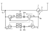
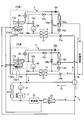
- This vehicle air conditioner includes a hot water circuit 5 (heat source cooling water circuit) that cools the first refrigeration cycle circuit 1, the second refrigeration cycle circuit 2, and the heat source 3, and the first refrigeration cycle circuit 1 and the second refrigeration cycle circuit 2. And a control device 6 for controlling the hot water circuit 5.
- a hot water circuit 5 heat source cooling water circuit
- the control device 6 includes a switching valve 7 constituted by a three-way valve, first electronic expansion valves 8a and 8b, compressors 9a and 9b, and a first electromagnetic valve 10a in the first refrigeration cycle circuit 1 and the second refrigeration cycle circuit 2. 10b, the second electromagnetic valves 11a, 11b and the like are controlled. However, the control signal transmitted from the control device 6 in this case is not shown.
- the switching valve 7 has a function of flowing hot water (an example of cooling water) of the hot water circuit 5 through the first water refrigerant heat exchanger 13 and the second water refrigerant heat exchanger 14 as shown by an arrow Y1.
- first refrigeration cycle circuit 1 and the second refrigeration cycle circuit 2 include a first water refrigerant heat exchanger 13 that performs heat exchange between the hot water circuit 5 and the first refrigeration cycle circuit 1, and the hot water circuit 5 and the second refrigeration cycle circuit 2.
- a second water refrigerant heat exchanger that performs heat exchange with the refrigeration cycle circuit 2;
- the hot water circuit 5 is configured with the engine as a heat source 3.
- the hot water circuit 5 includes an engine that is mounted on a vehicle and serves as the heat source 3, and a water pump 31 that circulates engine coolant.
- the hot water circuit 5 exchanges heat between the combustor 32 that burns fuel and raises the temperature of the hot water, the radiator 33 that radiates the temperature of the hot water to the outside air, and the conditioned air that flows toward the vehicle interior.
- a heater core 34 is disposed.
- the first refrigeration cycle circuit 1 and the second refrigeration cycle circuit 2 constitute a heat pump that pumps heat from the air through the first outdoor heat exchanger 15a and the second outdoor heat exchanger 15b, respectively. In the first outdoor heat exchanger 15a and the second outdoor heat exchanger 15b, the refrigerant and the outside air exchange heat.
- FIG. 2 is a table showing the control of the electronic expansion valve and the like by the control device 6. The operation of the first electromagnetic valves 10a and 10b and the second electromagnetic valves 11a and 11b in FIG. 1 will be described.
- the first refrigeration cycle circuit 1 and the second refrigeration cycle circuit 2 have the following four modes, respectively.
- the cooling mode heat is radiated by the water-refrigerant heat exchangers 13 and 14, the first outdoor heat exchanger 15a, and the second outdoor heat exchanger 15b, and the indoor heat exchanger (that is, the first indoor heat exchanger 17a and the second indoor heat exchanger 17b). Heat is absorbed by the heat exchanger 17b).
- the second electronic expansion valves 18a and 18b are fully opened, the first electronic expansion valves 8a and 8b are controlled in flow rate, and the temperatures of the indoor heat exchangers 17a and 17b functioning as evaporators are controlled.
- the first electromagnetic valves 10a and 10b are closed, and the second electromagnetic valves 11a and 11b are also closed.
- the heating mode heat is radiated by the water-refrigerant heat exchangers 13 and 14 and is absorbed by the first outdoor heat exchanger 15a and the second outdoor heat exchanger 15b.
- the second electronic expansion valves 18a and 18b control the flow rate, and control the temperatures of the first outdoor heat exchanger 15a and the second outdoor heat exchanger 15b that function as evaporators.
- the first electronic expansion valves 8a and 8b may be opened or closed. That is, the opening and closing of the first electronic expansion valves 8a and 8b is not related to the heating mode, but is closed in this embodiment.
- the first solenoid valves 10a and 10b are closed, and the second solenoid valves 11a and 11b are opened.
- the flow rate of the second electronic expansion valves 18a and 18b is controlled to control the temperatures of the first outdoor heat exchanger 15a and the second outdoor heat exchanger 15b that function as an evaporator.
- the first electronic expansion valves 8a and 8b also control the flow rate.
- the first solenoid valves 10a and 10b are opened.
- the second solenoid valves 11a and 11b are also opened.
- the water refrigerant heat exchangers 13 and 14 absorb heat or do nothing, and the first outdoor heat exchanger 15a and the second outdoor heat exchanger 15b dissipate heat. Therefore, the second electronic expansion valves 18a and 18b are fully opened.
- the first electronic expansion valves 8a and 8b may be opened or closed, but are closed in this embodiment.
- the first solenoid valves 10a and 10b are closed.
- the second solenoid valves 11a and 11b are opened.
- compressors 9a and 9b water refrigerant heat exchangers 13 and 14 ⁇ first electromagnetic valves 10a and 10b ⁇ (check valve portion) ⁇ second electromagnetic valves 11a and 11b ⁇ accumulator 19a , 19b ⁇ compressors 9a and 9b are formed. Therefore, check valves 16a and 16b are provided to prevent formation of unnecessary circuits in the heating and dehumidifying mode.
- FIG. 3 and 4 are examples of flowcharts of control executed in the control device 6 of FIG.
- the control device 6 performs a defrosting operation for defrosting the first refrigeration cycle circuit 1, which is one of the refrigeration cycle circuits, in the first outdoor heat exchanger 15 a. become. Then, the defrosting operation of the second refrigeration cycle circuit 2 which is the other refrigeration cycle is prohibited.
- step S31 it is determined whether or not the first refrigeration cycle circuit 1 is in the defrosting operation. If YES, the defrosting operation in the second refrigeration cycle circuit 2 is prohibited in step S35. That is, the heating operation of the second refrigeration cycle circuit 2 is continued. Then, the process proceeds to step S36.
- step S41 the temperature of the hot water in the hot water circuit 5 is compared with the discharge temperature of the high-temperature and high-pressure refrigerant discharged from the compressor 9a of the first refrigeration cycle circuit 1 (that is, the temperature of the high-pressure gas refrigerant). May be determined as NO in step S41.
- step S42 the first flow rate control valve 21a (FIG. 1) is opened so that the hot water of the hot water circuit 5 flows through the water-refrigerant heat exchanger 13.
- the first flow rate control valve 21a is controlled by the first flow rate control unit (step S42).
- step S41 when it is determined in step S41 that the temperature of the hot water is relatively low and the refrigerant discharge temperature of the first refrigeration cycle circuit 1 is higher than the temperature of the hot water (YES), the process proceeds to step S45. And the 1st flow control valve 21a is closed so that the warm water of the warm water circuit 5 may not flow through the water-refrigerant heat exchanger 13. After step S42 and step S45, the second flow rate control valve 21b is opened in step S43. The second flow rate control valve 21b is controlled by the second flow rate control unit (step S52).
- the temperature of the hot water in the hot water circuit 5 and the discharge temperature of the refrigerant flowing through the one refrigeration cycle circuit 1 are set. Compare. As a result, when it is determined that the one refrigeration cycle circuit 1 side can absorb heat, the hot water of the hot water circuit 5 is allowed to flow through the first water refrigerant heat exchanger 13.
- the defrosting efficiency of the first outdoor heat exchanger 15a in one refrigeration cycle circuit 1 using the heat of the hot water circuit 5 and shorten the defrosting time.
- the second flow rate control valve 21b is opened in step S43. Then, the heat of the refrigerant can be transmitted to the hot water circuit 5 through the other second water refrigerant heat exchanger 14.
- step S32 of FIG. 3 it is determined whether or not the second refrigeration cycle circuit 2 is in the defrosting operation. If YES, the defrosting operation in the first refrigeration cycle circuit 1 is prohibited in step S33. That is, the heating operation of the first refrigeration cycle circuit 1 is continued. Then, the process proceeds to step S34.
- step S51 the temperature of the hot water in the hot water circuit 5 and the discharge temperature of the high-temperature and high-pressure refrigerant discharged from the compressor 9b in the second refrigeration cycle circuit 2 (that is, the temperature of the high-pressure gas refrigerant) are compared. If the temperature of the hot water is high and NO is determined in step S51, it is determined that the second refrigeration cycle circuit 2 side can absorb heat, and in step S52, the hot water of the hot water circuit 5 is supplied to the water-refrigerant heat exchanger 14. The 2nd flow control valve 21b is opened so that it may flow.
- step S51 it may be determined that the temperature of the hot water is relatively low and the refrigerant discharge temperature of the second refrigeration cycle circuit 2 is higher than the temperature of the hot water (YES). In this case, it progresses to step S55 and the 2nd flow control valve 21b is closed so that the warm water of the warm water circuit 5 may not flow through the water-refrigerant heat exchanger 14. Then, after step S55, in step S53, the first flow control valve 21a is opened.
- the second refrigeration cycle circuit 2 side goes to the second water refrigerant heat exchanger 14.
- the opening degree of the second flow rate control valve 21b for flowing warm water is fully opened (step S43).
- coolant heat exchanger 14 heat-exchange. Therefore, the temperature of the hot water for heating can be maintained, and the heat pumped up by the second outdoor heat exchanger 15b of the other second refrigeration cycle circuit 2 is transferred to the other first refrigeration cycle circuit 1 via the hot water circuit 5. Can be handed over.
- the defrosting efficiency is achieved by using the heat absorbed from the air in the second refrigeration cycle circuit 2 and the heat absorbed from the hot water for defrosting the first refrigeration cycle circuit 1 via the hot water circuit 5. It is possible to improve and shorten the defrosting time.
- the hot water circuit 5 is composed of a circuit that cools the engine serving as the heat source 3 mounted on the vehicle.
- the hot water circuit 5 is composed of an engine that constitutes the heat source 3, a water pump 31 that circulates hot water that cools the engine, a first water refrigerant heat exchanger 13, a second water refrigerant heat exchanger 14, and fuel. And a combustor 32 that raises the temperature of the hot water.
- the hot water circuit 5 includes a radiator 33, a heater core 34, a first flow rate control valve 21a that adjusts the flow rate of hot water flowing into the first water refrigerant heat exchanger 13 and the second water refrigerant heat exchanger 14, respectively. And a second flow rate control valve 21b.
- the radiator 33 radiates heat to the outside air when the temperature of the hot water rises more than necessary.
- the heater core 34 warms the conditioned air that cools the heat source 3 and blows air into the passenger compartment.
- the first flow rate control valve 21a and the second flow rate control valve 21b can also be configured using well-known ON / OFF valves that are intermittent, not valves that can finely adjust the opening. When the flow rate is increased, the ON period may be lengthened.
- the first refrigeration cycle circuit 1 and the second refrigeration cycle circuit 2 include compressors 9a and 9b, indoor heat exchangers 17a and 17b, a first outdoor heat exchanger 15a, and a second outdoor heat exchanger 15b, respectively. And first electronic expansion valves 8a and 8b.
- High-pressure refrigerant flows through the first water refrigerant heat exchanger 13 and the second water refrigerant heat exchanger 14 through which hot water in the hot water circuit 5 flows. That is, the first water refrigerant heat exchanger 13 is disposed between the discharge port of the compressor 9a and the first outdoor heat exchanger 15a, and the second water refrigerant heat exchanger 14 is connected to the discharge port of the compressor 9b. It arrange
- the first refrigeration cycle circuit 1 and the second refrigeration cycle circuit 2 include check valves 16a and 16b, first electromagnetic valves 10a and 10b, and second electromagnetic valves 11a and 11b that prevent the refrigerant from flowing backward. And accumulators 19a and 19b for storing excess refrigerant.
- the temperature sensor 35 for hot water, the discharge temperature sensors 36a and 36b for detecting the discharge temperature, the temperature of the heat exchange fins of the first outdoor heat exchanger 15a and the second outdoor heat exchanger 15b are detected.
- Frost determination sensors 37a and 37b are provided. Signals from these sensors are connected to the control device 6.
- the hot water temperature sensor 35 measures the temperature of the hot water flowing through the first water refrigerant heat exchanger 13 and the second water refrigerant heat exchanger 14.
- the discharge temperature sensors 36a and 36b detect the discharge temperature of the refrigerant that has exited the compressors 9a and 9b.
- the first flow rate control unit (step S42) performs the first flow rate control.
- the valve 21a is closed. Accordingly, the hot water having a low temperature does not receive heat from the first refrigeration cycle circuit 1.
- step S42 If the discharge temperature of the first refrigeration cycle circuit 1 is not higher than the temperature of the hot water, the first flow control valve 21a is opened in step S42. Thus, the hot water transfers heat to the first refrigeration cycle circuit 1. Thereafter, in step S43, the second flow rate control valve 21b is opened. As a result, the hot water receives heat from the second refrigeration cycle circuit 2.
- the second flow control valve 21b is closed in step S55. Accordingly, the hot water having a low temperature does not receive heat from the second refrigeration cycle circuit 2.
- the second flow rate control valve 21b is opened in step S52. Thereby, the hot water transfers heat to the second refrigeration cycle circuit 2. Thereafter, the first flow control valve 21a is opened. Thereby, the hot water can receive heat from the first refrigeration cycle circuit 1.
- the second refrigeration cycle circuit 2 When the first refrigeration cycle circuit 1 is in the defrosting mode, the second refrigeration cycle circuit 2 is heating. Therefore, generally, the refrigerant discharge temperature of the second refrigeration cycle circuit 2 is higher than the temperature of hot water after the heater core 34.
- the portion that dissipates heat on the second refrigeration cycle circuit 2 side disappears, the refrigerant discharge temperature rises, and the refrigerant discharge temperature eventually becomes the temperature of the hot water. Get higher.
- the combustor 32 stops.
- the operational effects of the first embodiment will be described.
- the first refrigeration cycle circuit 1 when the first refrigeration cycle circuit 1 is in a defrosting operation for defrosting in the first outdoor heat exchanger 15a, the temperature of the hot water in the hot water circuit 5 and the first temperature as shown in FIG.
- the discharge temperature of the refrigerant flowing through the refrigeration cycle circuit 1 is compared.
- the warm water of the warm water circuit 5 is poured into the 1st water-refrigerant heat exchanger 13 with the 1st flow control valve 21a. Therefore, the defrosting efficiency of the 1st outdoor heat exchanger 15a in the 1st freezing cycle circuit 1 can be improved using the heat of warm water circuit 5, and defrost time can be shortened.
- the second refrigeration cycle circuit 2 when the second refrigeration cycle circuit 2 is in a defrosting operation for defrosting in the outdoor heat exchanger 15b, the temperature of the hot water in the hot water circuit 5 and the refrigerant flowing through the second refrigeration cycle circuit 2 as shown in FIG. Compare the discharge temperature. And when it determines with the 2nd freezing cycle circuit 2 being in the state which can absorb heat, the warm water of the warm water circuit 5 is poured into the 2nd water-refrigerant heat exchanger 14 with the 2nd flow control valve 21b. Therefore, the defrosting efficiency of the 2nd outdoor heat exchanger 15b in the 2nd freezing cycle circuit 2 can be improved using the heat of warm water circuit 5, and defrost time can be shortened.
- the defrosting efficiency is improved by utilizing the heat absorbed from the air in the other refrigeration cycle circuit 2 and the heat absorbed from the hot water for defrosting the one refrigeration cycle circuit 1 via the hot water circuit 5.
- the defrosting time can be shortened.
- heating of the vehicle interior and defrosting of each of the plurality of refrigeration cycle circuits can be efficiently performed using the heat generated by the engine. Further, the hot water can be heated by the combustor 32 when the temperature of the hot water is low. Further, since the hot water circuit 5 is often provided together with the engine in the lower part of the vehicle, the foot can be warmed by the heater core 34.
- the heat of the refrigerant is supplied from the first refrigeration cycle circuit 1 and the second refrigeration cycle circuit 2 to the first water refrigerant heat exchanger 13 and the second water refrigerant heat exchanger 14, and further, the first water refrigerant heat exchange through which hot water flows.
- the hot water in the hot water circuit 5 can be heated via the vessel 13 and the second water refrigerant heat exchanger 14.
- the temperature sensor 35 of the hot water is measured at a position before branching to the first water refrigerant heat exchanger 13 and the second water refrigerant heat exchanger 14, the number of sensors can be reduced.
- the first refrigeration cycle circuit 1 In the case where the first refrigeration cycle circuit 1 is in the defrosting operation, when the discharge temperature of the first refrigeration cycle circuit 1 is higher than the temperature of the hot water as shown in FIG. Heat transfer between the low-temperature hot water and the first refrigeration cycle circuit is prevented. Therefore, the defrosting of the first refrigeration cycle circuit 1 is not adversely affected. Thereby, it can prevent that the refrigerant
- the second refrigeration cycle circuit 2 when the discharge temperature of the second refrigeration cycle circuit 2 is higher than the temperature of the hot water as shown in FIG. Heat transfer between the low-temperature hot water and the second refrigeration cycle circuit is prevented. Therefore, heat transfer from the second refrigeration cycle circuit 2 side to the hot water side can be prevented. Thereby, it can prevent that the refrigerant
- hot water from the engine serving as the heat source 3 flows in parallel with the first water refrigerant heat exchanger 13 and the second water refrigerant heat exchanger 14 as shown in FIG.
- the operation can be changed so that hot water flows in series through the first water refrigerant heat exchanger 13 and the second water refrigerant heat exchanger 14 by operation of a plurality of flow path switching valves (also referred to as three-way valves).
- a main switching valve 7 (also simply referred to as a switching valve) uses hot water composed of engine cooling water in the hot water circuit 5 as a first water refrigerant heat exchanger 13 and a second water refrigerant heat exchanger 14. And in parallel.
- the first water refrigerant in the first water refrigerant heat exchanger 13 and the second water refrigerant heat exchanger 14 are provided on the inflow side and the outflow side, respectively.
- An upstream switching valve 7a is provided.
- a first downstream switching valve 7b, a second upstream switching valve 7c, and a second downstream switching valve 7d are further provided.
- the hot water flows from the main switching valve 7 through the first water refrigerant heat exchanger 13 and the second water refrigerant heat exchanger 14 in parallel.
- the control apparatus 6 forms the flow path in which the hot water forms the flow path through which the hot water flows through the first water refrigerant heat exchanger 13 and the second water refrigerant heat exchanger 14 in series from the main switching valve 7 (step S92). Is provided.
- the heating side can be the upstream side and the defrost side can be the downstream side.
- the warm water is first supplied to the second water refrigerant heat exchanger 14 on the heating side, and the first water refrigerant on the defrost side on the downstream side. Warm water is passed through the heat exchanger 13.
- the second series flow path shown in FIG. 8 flows warm water first through the first water refrigerant heat exchanger 13 on the heating side as in the flow shown by the solid line, and the second water refrigerant on the defrost side on the downstream side. Warm water is passed through the heat exchanger 14. Thereby, the heat absorbed from the refrigerant in the heating-side water-refrigerant heat exchanger can be used for defrosting the downstream-side water-refrigerant heat exchanger.
- any of the first water refrigerant heat exchanger 13 and the second water refrigerant heat exchanger 14 is the defrost side. Even if it becomes, it can be made to flow warm water first to the water refrigerant heat exchanger which is not a defrost side. Thereby, after warm water absorbs heat from the refrigerant side, the absorbed heat is transferred to the water / refrigerant heat exchanger on the defrosting side, and can be immediately used for defrosting.
- step S91 when the control starts, in step S91, the refrigerant discharge temperature of the first refrigeration cycle circuit 1 is detected by the discharge temperature sensor 36a that detects the discharge temperature of the refrigerant that has exited the compressor 9a, and the temperature of the hot water To be compared.
- the temperature of the warm water is detected by the warm water temperature sensor 35.
- step S92 forming the first series flow path forming unit, and the first series flow path of FIG. 7 is formed. That is, the first upstream switching valve 7a forms a flow path from the downstream of the second water refrigerant heat exchanger 14 to the upstream of the first water refrigerant heat exchanger 13, and the switching valve 7b is the first water refrigerant heat exchange. A flow path from the downstream side of the vessel 13 to the merging portion 5j is formed.
- the switching valve 7c forms a flow path from the branch portion 5b to the upstream side of the second water refrigerant heat exchanger 14.
- the switching valve 7 d forms a flow path from the downstream of the second water refrigerant heat exchanger 14 to the upstream of the first water refrigerant heat exchanger 13. In this way, the operation of the second switching valve 7d from the main switching valve 7 and the first upstream switching valve 7a is switched.
- step S92 of FIG. 9 forms a flow path in which hot water flows in series from the main switching valve 7 to the first water refrigerant heat exchanger 13 and the second water refrigerant heat exchanger 14 as shown in FIG.
- the series flow path forming unit is executed.
- step S93 the first flow control valve 21a is opened, and hot water is allowed to flow to the first water refrigerant heat exchanger 13.
- step S94 the 2nd flow control valve 21b is opened so that warm water may be heated by the 2nd freezing cycle circuit 2 under heating in Step S94.
- step S91 if the refrigerant discharge temperature is higher than the temperature of the hot water, the process proceeds to step S95 forming a parallel flow path forming unit. And the operation
- the switching valve 7a forms a flow path from the branch part 5b to the upstream of the first water refrigerant heat exchanger 13, and the switching valve 7b flows from the downstream of the first water refrigerant heat exchanger 13 to the junction part 5j.
- the switching valve 7 c forms a flow path from the branch portion 5 b to the upstream side of the second water refrigerant heat exchanger 14.
- the switching valve 7d forms a flow path from the downstream of the second water refrigerant heat exchanger 14 to the junction 5j.
- the parallel flow path forming unit comprising step S95 of FIG. 9 is formed in which the hot water forms a flow path in which the hot water flows from the main switching valve 7 through the first water refrigerant heat exchanger 13 and the second water refrigerant heat exchanger 14 in parallel. Is executed.
- step S96 the first flow control valve 21a in FIG. 6 is closed, and then the second flow control valve 21b is opened in step S94.
- step S101 the refrigerant discharge temperature of the second refrigeration cycle circuit 2 is detected by the discharge temperature sensor 36b that detects the discharge temperature of the refrigerant that has exited the compressor 9b, and the temperature of the hot water is detected. Compare.
- step S102 If the refrigerant discharge temperature is not higher than the temperature of the hot water, the process proceeds to step S102. And the operation
- the switching valve 7 b forms a flow path from the downstream of the first water refrigerant heat exchanger 13 to the upstream of the second water refrigerant heat exchanger 14.
- the switching valve 7 c forms a flow path from the downstream of the first water refrigerant heat exchanger 13 to the upstream of the second water refrigerant heat exchanger 14.
- the switching valve 7d forms a flow path from the downstream of the second water refrigerant heat exchanger 14 to the junction 5j. In this way, the operation of the second switching valve 7d from the main switching valve 7 and the first upstream switching valve 7a is switched. Thereby, the flow path through which hot water flows in series from the main switching valve 7 to the first water refrigerant heat exchanger 13 and the second water refrigerant heat exchanger 14 is formed.
- step S103 the second series flow path forming unit including step S102 of FIG. 10 is executed.
- step S103 the 2nd flow control valve 21b is opened, and the 1st flow control valve 21a is then opened in step S104.
- step S101 if the refrigerant discharge temperature is higher than the temperature of the hot water, the process proceeds to step S105. And the operation
- the control operation in step S105 is the same as the control operation in step S95. That is, the switching valve 7a forms a flow path from the branch part 5b to the upstream of the first water refrigerant heat exchanger 13, and the switching valve 7b flows from the downstream of the first water refrigerant heat exchanger 13 to the junction part 5j. Form a road.
- the switching valve 7 c forms a flow path from the branch portion 5 b to the upstream side of the second water refrigerant heat exchanger 14.
- the switching valve 7d forms a flow path from the downstream of the second water refrigerant heat exchanger 14 to the junction 5j.
- step S105 the parallel flow path forming unit including step S105 is performed in which the hot water forms a flow path in which the main water switching valve 7 and the first water refrigerant heat exchanger 13 and the second water refrigerant heat exchanger 14 flow in parallel.
- step S106 the 2nd flow control valve 21b is closed, and warm water with low temperature is not allowed to flow into the 2nd water-refrigerant heat exchanger 14.
- step S104 the first flow control valve 21a is opened.
- a flow path is switched by the switching valve 7a from the switching valve 7a, and warm water flows through the 1st water refrigerant heat exchanger 13 and the 2nd water refrigerant heat exchanger 14 in parallel, or flows in series. Can be switched.
- the heat of a warm water circuit can be utilized for defrosting, and the warm water of a warm water circuit can be heated from a refrigerant
- the heat absorbed from the refrigerant in the heating-side water-refrigerant heat exchanger can be immediately used for defrosting the downstream-side water-refrigerant heat exchanger. Furthermore, in the case of a basic configuration that forms a parallel flow path formed by the parallel flow path forming section, the heat given to the hot water from the water / refrigerant heat exchanger of the refrigeration cycle circuit that is not being defrosted flows through the hot water circuit. If it does not turn, it will not be given to the refrigeration cycle circuit during defrosting.
- the heat given to the hot water from the water / refrigerant heat exchanger of the refrigeration cycle circuit that is not defrosting is immediately downstream without going around the hot water circuit. It can be given to the refrigeration cycle circuit during defrosting.
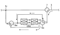
- coolant heat exchanger 14 are arrange
- the first water refrigerant heat exchanger 13 and the second water refrigerant heat exchanger 14 thus connected are collectively referred to as a series body 1314.
- direction of the warm water which flows into this serial body 1314 can be changed.
- hot water flows from the hot water circuit 5 through the main switching valve 7 through the first water refrigerant heat exchanger 13 and the second water refrigerant heat exchanger 14 in series.
- the first water refrigerant heat exchanger 13 and the second water refrigerant heat exchanger 14 are connected in series, and hot water is supplied from the hot water circuit 5 via the main switching valve 7.
- the serial body upstream side switching valve 7ac and the downstream side of the serial body composed of two valves on the upstream side and the downstream side of the serial body 1314 of the first water refrigerant heat exchanger 13 and the second water refrigerant heat exchanger 14 And a switching valve 7bd.
- a first switching flow path that leads to a flow path between the second water refrigerant heat exchanger 14 and the serial body downstream switching valve 7bd is connected to the serial switching upstream switching valve 7ac.
- a second switching flow path that leads to a flow path between the serial body upstream switching valve 7ac and the first water-refrigerant heat exchanger 13 is connected to the serial body downstream switching valve 7bd.
- the control device 6 uses the series body upstream side switching valve 7ac and the series body downstream side switching valve 7bd to change the direction of the hot water flowing through the series body 1314 from the second water refrigerant heat exchanger 14 to the first water refrigerant as shown in FIG. It has the 1st serial body flow path formation part set so that it may flow into the heat exchanger 13.
- the first serial body flow path forming unit connects the main switching valve 7 and the serial body upstream side switching valve 7ac to hot water. Is switched from the main switching valve 7 to the downstream side of the second water refrigerant heat exchanger 14 through the first switching flow path. Further, the first serial body flow path forming unit switches the serial body downstream side switching valve 7bd so that the hot water flows through the second switching flow path from the upstream side of the first water refrigerant heat exchanger 13 toward the merging portion 5j. .
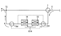
- control device 6 changes the direction of the hot water flowing to the series body 1314 from the first series refrigerant switching exchanger 7ac and the series series downstream switching valve 7bd from the first water refrigerant heat exchanger 13 to the second water refrigerant heat exchanger.
- 14 has a second serial body flow path forming portion that is set so as to flow through the same.
- the second serial body flow path forming unit starts the serial body upstream side switching valve 7ac as shown in FIG. It switches so that it may flow to the upstream of the 1st water refrigerant
- the second serial body flow path forming unit switches the serial body downstream side switching valve 7bd so that the hot water flows from the downstream side of the second water refrigerant heat exchanger 14 to the junction 5j.
- the setting of the first series channel and the setting of the second series channel may be alternately switched at predetermined time intervals. That is, the control device 6 includes an alternate flow path forming unit that alternately switches the direction of hot water flowing in the serial body 1314 in the opposite direction every predetermined time by the serial body upstream side switching valve 7ac and the serial body downstream side switching valve 7bd. .
- the first water is formed by the second serial body flow path forming unit (step S144) that is set to flow from the first water refrigerant heat exchanger 13 to the second water refrigerant heat exchanger.
- Hot water absorbs heat from the refrigerant by the refrigerant heat exchanger 13.
- the defrosting can be performed efficiently by flowing the absorbed hot water from the first water refrigerant heat exchanger 13 to the second water refrigerant heat exchanger 14.
- the second water-refrigerant heat exchanger 14 is configured by the first serial body flow path forming portion that is set to flow from the second water-refrigerant heat exchanger 14 to the first water-refrigerant heat exchanger 13.
- the hot water absorbs heat from the refrigerant. And defrosting can be performed efficiently by flowing the absorbed hot water through the first water-refrigerant heat exchanger 13.
- the hot water flows in parallel to the first water refrigerant heat exchanger 13 and the second water refrigerant heat exchanger 14 by the alternate flow path forming unit that switches the direction of the hot water flowing in the series body 1314 at predetermined time intervals.
- the alternate flow path forming unit that switches the direction of the hot water flowing in the series body 1314 at predetermined time intervals.
- These switching valves only need to add two switching valves, that is, a series body upstream switching valve 7ac and a series body downstream switching valve 7bd, to the main switching valve, the configuration of the valves can be simplified.
- FIG. 14 shows a flowchart of control of the third embodiment.
- the control starts when the first refrigeration cycle circuit 1 and the second refrigeration cycle circuit 2 are simultaneously in the heating operation.
- step S141 constituting the first serial body flow path forming unit
- the serial body upstream side switching valve 7ac switches the hot water to flow from the main switching valve 7 to the downstream side of the second water refrigerant heat exchanger 14. It is done.
- the serial body downstream side switching valve 7bd is switched so that hot water flows from the upstream side of the first water refrigerant heat exchanger 13 to the junction 5j.
- step S142 when a predetermined time has elapsed, the process proceeds to step S143, and the count time of the timer is reset. Moreover, in step S144 which comprises a 2nd serial body flow path formation part, the serial body upstream switching valve 7ac is switched so that warm water may flow from the main switching valve 7 to the upstream of the 1st water refrigerant
- step S145 it is determined whether a predetermined time has elapsed, the control is shifted to step S146, and the timer time is reset.
- Steps S142 and 143 and Steps S145 and 146 constitute an alternate flow path forming unit. Although omitted, when the operation stop is instructed during the circulation of the flowchart, the control is terminated.
- the direction of the hot water flowing through the serial body 1314 can be changed. Moreover, since it has the alternate flow path formation part which switches the direction of the warm water which flows into the serial body 1314 for every predetermined time, warm water makes the 1st water refrigerant heat exchanger 13 and the 2nd water refrigerant heat exchanger 14 artificially. The same effect as flowing in parallel can be obtained. And the number of the serial body upstream side switching valve 7ac and the serial body downstream side switching valve 7bd which switch a flow path can be decreased. (Fourth embodiment) The fourth embodiment of FIG.
- the 15 includes a plurality of refrigeration cycle circuits 1 and 2 and a hot water circuit 5 that cools the heat source, and a control device 6 that controls each of the refrigeration cycle circuits 1 and 2 and the hot water circuit 5.
- the heat of the first water refrigerant heat exchanger 13 that performs heat exchange between the hot water circuits 5 and 43 and one of the refrigeration cycle circuits 1, and the heat of the hot water circuits 5 and 43 and the other refrigeration cycle circuit 2.
- a second water-refrigerant heat exchanger 14 that performs replacement.
- the configuration of the second embodiment or the configuration of the third embodiment can be applied to the configuration of the fourth embodiment.
- the hot water circuit has a hot water circuit 5 constituting a loop passing through the heat source 3 and an independent hot water circuit 43 (independent cooling water circuit) forming a loop separated from the heat source 3.
- the plurality of refrigeration cycle circuits 1 and 2 constitute a heat pump that draws heat from the air through the first outdoor heat exchanger 15a and the second outdoor heat exchanger 15b, respectively.
- the first refrigeration cycle circuit 1 and the second refrigeration cycle circuit 2 cool or heat the passenger compartment.
- the hot water circuit 5, the first refrigeration cycle circuit 1, and the second refrigeration cycle circuit 2 transfer heat through the first water refrigerant heat exchanger 13 and the second water refrigerant heat exchanger 14.
- arrows Y161 and Y162 are provided between the first water refrigerant heat exchanger 13 and the second water refrigerant heat exchanger 14 by a dedicated independent water pump 42.
- the independent water pump 42 is a non-volumetric pump similar to the water pump 31 that allows fluid to flow by the rotation of the impeller.
- operation is transmitted to the refrigerating cycle circuit in defrosting via the independent hot water circuit 43, for example.
- the independent hot water circuit 43 and the hot water circuit 5 passing through the engine are disconnected without communication, and the temperature of the hot water circuit 5 is lowered even if the heat of the independent hot water circuit 43 is fully used for defrosting. do not do.
- the hot water circuit 5 passing through the engine can supply heat from the engine to the heater core 34 by the engine-side water pump 31, so that the temperature of the heater core 34 does not decrease and heating performance can be ensured. That is, in the independent hot water circuit 43, the hot water can be circulated through the first water refrigerant heat exchanger 13 and the second water refrigerant heat exchanger 14 independently from the hot water circuit 5.
- control device 6 When one of the plurality of refrigeration cycle circuits 1 and 2 is in the defrosting operation for defrosting in the first outdoor heat exchanger 15a, the control device 6 causes the hot water in the hot water circuits 5 and 43 to The temperature and the discharge temperature of the refrigerant flowing through one refrigeration cycle circuit 1 are compared.
- the hot water of the hot water circuits 5 and 43 is caused to flow to the first water refrigerant heat exchanger 13.
- An independent water pump 42 and a first flow control valve 21a are provided to flow this warm water.
- a switching valve 7 is provided for flowing hot water from the hot water circuit 5 passing through the heat source 3 to the first water refrigerant heat exchanger 13 and the second water refrigerant heat exchanger 14.
- the hot water is circulated through the independent hot water circuit 43, and the hot water circuit is made independent of the hot water circuit flowing through the engine.
- the hot water circuits 5 and 43 can be heated by the heat of the refrigerant in the refrigeration cycle circuit.
- the switching valve 7 can separate the independent hot water circuit 43 from the hot water circuit.
- step S161 When the control starts in the heating mode, it is determined in step S161 whether the first refrigeration cycle circuit 1 is in the defrosting operation. If the first refrigeration cycle circuit 1 is not in the defrosting operation, it is determined in step S162 whether the second refrigeration cycle circuit 2 is in the defrosting operation. When the second refrigeration cycle circuit 2 is in the defrosting operation in step S162, the defrosting operation of the first refrigeration cycle circuit 1 is prohibited in step S163 and the heating operation is continued. Then, the process proceeds to Step 164.
- step S164 Details of step S164 are illustrated in FIG.
- step S171 of FIG. 17 it is determined whether or not the discharge temperature of the compressor 9b of the second refrigeration cycle circuit 2 is higher than the temperature of the hot water. If the discharge temperature is not higher than the temperature of the hot water, the second flow rate control valve 21b is opened in step S172. Next, the 1st flow control valve 21a is opened at Step S173.
- step S174 the switching valve 7 is switched to the separated state as shown in FIG. 15, and the hot water circuit 5 and the independent hot water circuit 43 are separated.
- step S175 the independent water pump 42 (independent W / P) is turned on.
- step S171 If it is determined in step S171 that the discharge temperature of the compressor of the second refrigeration cycle circuit 2 is higher than the temperature of the hot water, if the discharge temperature is higher than the temperature of the hot water, the second flow control valve 21b in step S176. Close. Next, the 1st flow control valve 21a is opened at Step S177. In step S178, the switching valve 7 is switched to the communication state as shown in FIG. 1, and the hot water circuit 5 and the independent hot water circuit 43 are communicated. Next, in step S179, the independent water pump 42 (independent W / P) is turned OFF.
- Step S161 of FIG. 16 the defrosting operation of the second refrigeration cycle circuit 2 is prohibited in step S165, and the heating operation is continued. Then, the process proceeds to Step 166.
- step S166 Details of step S166 are illustrated in FIG.
- step S181 of FIG. 18 it is determined whether or not the discharge temperature of the compressor 9a of the first refrigeration cycle circuit 1 is higher than the temperature of the hot water. If the discharge temperature is not higher than the temperature of the hot water, the first flow control valve 21a is opened in step S182. Next, the 2nd flow control valve 21b is opened at Step S183. In step S184, the switching valve 7 is switched to the separated state as shown in FIG. 15, and the hot water circuit 5 and the independent hot water circuit 43 are separated. Next, the independent water pump 42 is turned on in step S185.
- step S181 If it is determined in step S181 whether or not the discharge temperature of the compressor 9a of the first refrigeration cycle circuit 1 is higher than the temperature of the hot water, if the discharge temperature is higher than the temperature of the hot water, the first flow rate control valve in step S186. 21a is closed. Next, the 2nd flow control valve 21b is opened at Step S187. In step S188, the switching valve 7 is switched to the communication state as shown in FIG. 1, and the hot water circuit 5 and the independent hot water circuit 43 are communicated. Next, in step S189, the independent water pump 42 is turned off.
- the refrigerant from other refrigeration cycle circuits is added to the refrigeration cycle circuit that performs the defrosting operation by the independent hot water circuit 43 that connects the first water refrigerant heat exchanger 13 and the second water refrigerant heat exchanger 14. Can supply the heat.
- the defrosting efficiency of the first outdoor heat exchanger 15a and the second outdoor heat exchanger 15b can be improved, and the defrosting time can be shortened.
- the warm water is allowed to flow by separating the independent warm water circuit 43 and the warm water circuit 5 passing through the heat source 3, the temperature of the warm water in the warm water circuit 5 passing through the heat source 4 is not extremely lowered.
- the first to fourth embodiments described above are systems having a plurality of water refrigerant heat exchangers, but cannot perform dehumidifying heating.
- the fifth embodiment shown in FIG. 19 provides a system that can perform dehumidifying heating, set a plurality of zones capable of air conditioning, and perform zone air conditioning for each zone.
- the target temperature can be adjusted for each zone in the bus.
- the present invention provides a reheat type air conditioner that does not require additional parts such as a damper for switching the flow of air conditioned air in the air conditioning duct and can perform fine temperature control.
- the configuration of the second embodiment and the configuration of the third embodiment can be applied to the fifth embodiment.
- Reheat cores 17ah and 17bh (that is, the first reheat core 17ah and the second reheat core 17bh) through which the hot water of the hot water circuit 5 flows are provided adjacent to the indoor heat exchangers 17a and 17b.
- the conditioned air that has passed through the indoor heat exchangers 17a and 17b is reheated by the reheat cores 17ah and 17bh.
- the degree of reheating that is, the degree of temperature adjustment is adjusted by flow control valves 17ahv and 17bhv that adjust the amount of hot water flowing through the reheat cores 17ah and 17bh, respectively.
- Other configurations are the same as those in FIG.
- ⁇ ⁇ Reheat cores 17ah and 17bh are installed in the air conditioner unit on the ceiling of the vehicle to enable dehumidifying heating operation.
- the air conditioner unit includes one set of the indoor heat exchanger 17a, the reheat core 17ah, the indoor heat exchanger 17a, the blower 17ahf that blows air to the reheat core 17ah, the first electronic expansion valve 8a, and the flow control valve 17ahv. This one set is integrated as a module 17aM (first module) as indicated by a broken line.
- the reheat core 17bh side is also integrated as a module 17bM (second module).
- module 17bM second module
- step S201 the measured values from various sensors such as the inside air temperature, the outside air temperature, the inside air humidity, and the temperature of the hot water, which are the air temperatures inside the vehicle, are read.
- step S202 the temperature setting value set for each zone, that is, for each area handled by the arranged module, is read.
- the operation mode is determined in step S203, and the process proceeds to any of steps S204, S205, and S206 according to the determined operation mode.
- the operation mode may be determined from an operation signal from the vehicle driver or a deviation between the vehicle interior temperature and the current temperature setting value.
- the process proceeds to step S204, and the blowers 17ahf and 17bhf are energized.
- step S205 the process proceeds to step S205 to form a cooling cycle. That is, heat is radiated by the outdoor heat exchangers 15a and 15b, the air volume of the blowers 17ahf and 17bhf is controlled to cool the room by the indoor heat exchangers 17a and 17b, and variable capacity control of the compressors 9a and 9b is executed. . Also, control of the second electronic expansion valves 18a, 18b, etc. is executed.
- step S206 the process proceeds to step S206 to form a heating cycle.
- Heat is absorbed by the outdoor heat exchangers 15a and 15b in FIG. 19, dehumidified by the indoor heat exchangers 17a and 17b, the air volume of the blowers 17ahf and 17bhf is controlled, and variable capacity control of the compressors 9a and 9b is executed. Control of the second electronic expansion valves 18a, 18b and the like is also executed.
- the conditioned air dehumidified by the indoor heat exchangers 17a and 17b is reheated by the reheat cores 17ah and 17bh. The degree of reheat controls the amount of hot water flowing through the reheat cores 17ah and 17bh by the opening degree of the flow control valve 17ah1v and the like.
- the reheat core 17ah and 17bh which reheat the conditioned wind which passes indoor heat exchanger 17a, 17b with the heat
- modules 17aM1 to 17aM3 are provided in one refrigeration cycle circuit as shown in FIG. (First module) is provided. Further, as shown in FIG. 22, modules 17aM1 to 17bM3 are arranged so that air conditioning on the left side of the bus is performed in the first refrigeration cycle circuit 1 and air conditioning on the right side of the bus is performed in the second refrigeration cycle circuit 2. Yes.
- the configuration of the second embodiment and the configuration of the third embodiment can be applied to the sixth embodiment.
- the first embodiment of FIG. 1 is a system having a plurality of water refrigerant heat exchangers, but cannot be dehumidified and heated because it does not have a reheat core in combination with an indoor heat exchanger composed of an evaporator. Moreover, since only one indoor heat exchanger consisting of an evaporator is provided for one refrigeration cycle circuit, there is a problem that zone air conditioning cannot be set finely.
- the sixth embodiment has three or more locations when the air-conditioning area is long in the front and rear direction like a bus, or when the vehicle body is connected to two or more cars for mass transportation.
- a system that can perform zone air conditioning is provided.
- individual temperature adjustment is possible for each zone in the bus.
- the present invention provides an air conditioner capable of controlling the temperature without any additional parts such as a damper for switching the flow of the conditioned air in the air conditioning duct.
- reheat cores 17ah1, 17ah2, and 17ah3 (first reheat cores) through which hot water of the hot water circuit 5 flows are provided adjacent to the indoor heat exchangers 17a1 to 17a3 (first indoor heat exchangers). Yes.
- the conditioned air that has passed through the indoor heat exchangers 17a1, 17a2, and 17a3 is reheated by the reheat cores 17ah1, 17ah2, and 17ah3, respectively.
- the degree of reheat that is, the degree of temperature adjustment is adjusted by a flow control valve 17ah1v that adjusts the amount of hot water flowing into the reheat cores 17ah1, 17ah2, and 17ah3, respectively.
- Other configurations are the same as those in FIG. The same applies to the indoor heat exchangers 17b1 to 17b3 (second indoor heat exchanger) side.
- the reheat core 17ah1 etc. is installed in the air conditioner unit on the ceiling of the vehicle to enable dehumidification heating operation.
- the air conditioner unit includes an indoor heat exchanger 17a1, an reheat core 17ah1, an air blower that blows air to the indoor heat exchanger 17a1, the reheat core 17ah1, a first electronic expansion valve 8a1, and a flow control valve 17ah1v. This one set is integrated as a module 17aM1.
- the module 17aM2 having the first electronic expansion valve 8a2 and the flow control valve 17ah2v is modularized as a set of an indoor heat exchanger, a reheat core, and a fan that blows air to the indoor heat exchanger and the reheat core.
- the reheat cores 17bh1 to 17bh3 (second reheat core) side are also integrated as modules 17bM1 to 17bM3 (second module).
- the temperature control for each zone is finely tuned, and the arrangement of each module is devised, so that the size of the unit in the longitudinal direction of the vehicle and special correspondence such as connected buses etc. Can respond flexibly.
- FIG. 22 is a layout view of modules 17aM1 to 17aM3 and 17bM1 to 17bM3 in the sixth embodiment, as viewed from above the ceiling part of the articulated bus in which two vehicle bodies are connected by a bellows-shaped passage 50.
- a plurality of reheat cores 17ah1 to 17ah3 and 17bh1 to 17bh3 are provided in each of the refrigeration cycle circuits 1 and 2. Therefore, the inside of the vehicle can be air-conditioned by dispersing the heating air from the plurality of reheat cores.
- the reheat cores 17ah1 to 17bh3 form a module together with the indoor heat exchangers 17a1 to 17b3 and the blower that blows air to each indoor heat exchanger, and the modules are arranged at least at six locations on the vehicle ceiling. Therefore, the zone air conditioning can be determined and set finely for each module.
- a seventh embodiment will be described.
- a gas injection cycle is adopted in the refrigeration cycle circuit.
- the gas injection cycle has a configuration in which two expansion valves 55a1 and 55a2 are provided in a decompression section of a single-stage cycle, and a gas-liquid separator 56a is further provided between the two expansion valves 55a1 and 55a2.
- the configuration in which the gas injection cycle of the seventh embodiment is adopted in the refrigeration cycle circuit can be applied to any of the above embodiments.
- the high-pressure liquid refrigerant that has exited the first water-refrigerant heat exchanger 13 that forms a condenser is decompressed to an intermediate-pressure injection pressure by the upstream expansion valve 55a1, and is a gas-liquid two-phase with a predetermined dryness. And enters the gas-liquid separator 56a. In the gas-liquid separator 56a, it is separated into a saturated gas refrigerant and a saturated liquid refrigerant. Thereafter, the saturated liquid refrigerant is further decompressed by the downstream expansion valve 55a2 and enters the outdoor heat exchanger 15a at a low pressure. The outdoor heat exchanger 15a absorbs heat and evaporates and is sucked into the compressor 9a.
- the downstream side expansion valve 55a2 is configured by a fixed throttle.
- the solenoid valve 55a3 short-circuits both ends of the expansion valve 55a2 to flow the refrigerant.
- the differential pressure valve 57a is closed and no gas injection is performed.
- the expansion valve 55a2 and the differential pressure valve 57a can be integrated with the electromagnetic valve 55a3 and the like as an integrated valve.
- the flow rate of the refrigerant flowing through the outdoor heat exchanger 15a composed of an evaporator is reduced.
- the specific volume of the refrigerant in the outdoor heat exchanger 15a is reduced by reducing the degree of dryness of the outdoor heat exchanger 15a, and the pressure loss of the refrigerant flow on the outdoor heat exchanger 15a side is reduced.
- the compressor suction pressure increases and the compression work can be further reduced.
- two expansion valves 55b1 and 55b2 are provided in the decompression section, and a gas-liquid separator 56b is further provided between the two expansion valves 55b1 and 55b2.
- the high-pressure liquid refrigerant that has exited the second water refrigerant heat exchanger 14 that forms the condenser is decompressed to an intermediate injection pressure by the upstream expansion valve 55b1, and is a gas-liquid two-phase with a predetermined dryness. And enters the gas-liquid separator 56b. In the gas-liquid separator 56b, it is separated into a saturated gas refrigerant and a saturated liquid refrigerant.
- the saturated liquid refrigerant is further depressurized by the downstream side expansion valve 55b2, enters the outdoor heat exchanger 15b composed of a low-pressure evaporator, absorbs heat and evaporates, and is sucked into the compressor 9b.
- the saturated gas refrigerant is injected into the compression chamber in the compressor 9b.
- the first refrigeration cycle circuit 1 and the second refrigeration cycle circuit 2 are gas injection cycles. Therefore, the interior of the vehicle can be air-conditioned not only by the effective use of hot water by a plurality of refrigeration cycles but also by an efficient refrigeration cycle, and further energy saving can be achieved.
- the control device 6 is configured as an air conditioning control device (air conditioner ECU), but may be configured separately for the first refrigeration cycle circuit and the second refrigeration cycle side. If divided into two refrigeration cycle circuits, in the event of a failure, one-side operation that does not fail may be possible. Moreover, since the capacity
- Step S43 in FIG. 4 and step S53 in FIG. 5 may be brought immediately after the start.
- the flow control valve 41 indicated by the broken line is not provided, and this portion is merely a pipe portion.
- the flow control valve 41 is changed to the broken line portion. It is also possible to add.
- the temperature of the hot water measured by the sensor was compared with the discharge temperature of the cycle during defrosting, and the temperature of the hot water is the refrigerant discharge temperature of the cycle not being defrosted or a constant coefficient (0 to 0).
- the temperature multiplied by (range 1) may be compared as the temperature of the hot water.
Landscapes
- Engineering & Computer Science (AREA)
- Physics & Mathematics (AREA)
- Mechanical Engineering (AREA)
- Thermal Sciences (AREA)
- General Engineering & Computer Science (AREA)
- Chemical & Material Sciences (AREA)
- Combustion & Propulsion (AREA)
- Air-Conditioning For Vehicles (AREA)
- Compression-Type Refrigeration Machines With Reversible Cycles (AREA)
Abstract
冷凍サイクル装置は、第1冷凍サイクル回路(1)と、第2冷凍サイクル回路(2)と、熱源(3)を冷却する温水回路(5)と、第1冷凍サイクル回路の冷媒と温水回路の冷却水が熱交換する第1水冷媒熱交換器(13)と、第2冷凍サイクル回路の冷媒と温水回路の冷却水が熱交換する第2水冷媒熱交換器(14)と、を備える。第1冷凍サイクル回路と第2冷凍サイクル回路とは、一方が除霜運転の時に他方が暖房運転を行うように制御される。これにより、同時に除霜運転を行わない。制御装置(6)は、第1冷凍サイクル回路が除霜運転になり、第1冷凍サイクル回路が温水から吸熱できる状態であると判定した場合は、第1水冷媒熱交換器(13)に温水回路(5)の温水を流して、冷媒と熱交換させる。一方の冷凍サイクル回路で吸熱した熱を、温水回路を介して他方の冷凍サイクル回路の除霜に活用でき、除霜効率を向上させ除霜時間が短縮できる。
Description
本出願は、当該開示内容が参照によって本出願に組み込まれた、2014年7月23日に出願された日本特許出願2014-150103および、2015年7月2日に出願された日本特許出願2015-133794を基にしている。
本開示は、複数のヒートポンプを構成する冷凍サイクル回路と複数の水冷媒熱交換器を持ち、一方のヒートポンプで空気中から吸熱した熱を、温水回路を介して他方のヒートポンプ側に移し、他方の除霜運転に活用できるようにした冷凍サイクル装置に関する。
従来技術となる特許文献1は、複数の冷凍サイクル回路を持つ装置を開示している。この装置の目的は、熱の供給を継続しながら除霜でき、更に、除霜を実行しても、熱の供給量の変動を抑制することができるヒートポンプ装置を提供することにある。このため、ひとつの冷凍サイクル回路が除霜運転するときに、他のひとつの冷凍サイクル回路が熱の供給量を増加させることができるヒートポンプ装置を提供している。しかし、従来技術では、複数の冷凍サイクル回路の熱と温水回路の熱とを有効に活用できずに除霜時間が比較的長くなる場合がある。
本開示は、複数の冷凍サイクル回路と温水回路とを有する冷凍サイクル装置において、第1の冷凍サイクル回路で吸熱した熱を、温水回路を介して第2の冷凍サイクル回路の除霜に活用することで、除霜効率を向上させ除霜時間の短縮を図ることを目的とする。
従来技術として列挙された特許文献の記載内容は、この明細書に記載された技術的要素の説明として、参照によって導入ないし援用することができる。
本開示の一態様によると、第1冷凍サイクル回路と、第2冷凍サイクル回路と、熱源を冷却し車室内に送風する空調風を温めるヒータコアを有する熱源冷却水回路と、第1冷凍サイクル回路の作動と第2冷凍サイクル回路の作動と熱源冷却水回路の作動とを制御する制御装置と、熱源冷却水回路を流れる冷却水と第1冷凍サイクル回路を流れる冷媒との熱交換を行う第1水冷媒熱交換器と、熱源冷却水回路を流れる冷却水と第2冷凍サイクル回路を流れる冷媒との熱交換を行う第2水冷媒熱交換器と、を備える。第1冷凍サイクル回路は、第1室外熱交換器を介して空気中から熱を汲み上げるヒートポンプを構成し、第2冷凍サイクル回路は、第2室外熱交換器を介して空気中から熱を汲み上げるヒートポンプを構成する。制御装置は、第1冷凍サイクル回路が第1室外熱交換器における除霜のための除霜運転を行うとき、熱源冷却水回路の冷却水の温度と第1冷凍サイクル回路を流れる高圧ガス冷媒の温度とを比較し、第1冷凍サイクル回路が吸熱できる状態であると制御装置が判定した場合は、第1水冷媒熱交換器に熱源冷却水回路の冷却水を流すように熱源冷却水回路を制御する第1流量制御部を備える。制御装置は、第2冷凍サイクル回路が第2室外熱交換器における除霜のための除霜運転を行うとき、熱源冷却水回路の冷却水の温度と第2冷凍サイクル回路を流れる高圧ガス冷媒の温度とを比較し、第2冷凍サイクル回路が吸熱できる状態であると制御装置が判定した場合は、第2水冷媒熱交換器に熱源冷却水回路の冷却水を流すように熱源冷却水回路を制御する第2流量制御部を備える。
これによれば、第1冷凍サイクル回路が室外熱交換器における除霜のための除霜運転になると、熱源冷却水回路の冷却水の温度と第1冷凍サイクル回路を流れる高圧ガス冷媒の温度とを比較する。第1冷凍サイクル回路が吸熱できる状態であると判定した場合は、第1水冷媒熱交換器に熱源冷却水回路の冷却水を流すから、熱源冷却水回路の熱を利用して第1冷凍サイクル回路における室外熱交換器の除霜効率を向上させ、除霜時間の短縮を図ることができる。また、第2水冷媒熱交換器によって、第2冷凍サイクル回路と冷却水との熱交換を行い、冷却水の温度低下を抑制できる。
また、第2冷凍サイクル回路が室外熱交換器における除霜のための除霜運転になると、熱源冷却水回路の冷却水の温度と第2冷凍サイクル回路を流れる高圧ガス冷媒の吐出温度とを比較する。第2冷凍サイクル回路が吸熱できる状態であると判定した場合は、第2水冷媒熱交換器に熱源冷却水回路の冷却水を流すから、熱源冷却水回路の熱を利用して第2冷凍サイクル回路における室外熱交換器の除霜効率を向上させ、除霜時間の短縮を図ることができる。更に、第1水冷媒熱交換器によって、第1冷凍サイクル回路と冷却水との熱交換を行い、冷却水の温度低下を抑制できる。
本開示他の一態様によると、 第1冷凍サイクル回路と、第2冷凍サイクル回路と、熱源を冷却し車室内に送風する空調風を温めるヒータコアを有する熱源冷却水回路と、熱源冷却水回路を流れる冷却水と第1冷凍サイクル回路を流れる冷媒との熱交換を行う第1水冷媒熱交換器と、熱源冷却水回路を流れる冷却水と第2冷凍サイクル回路を流れる冷媒との熱交換を行う第2水冷媒熱交換器と、第1水冷媒熱交換器と第2水冷媒熱交換器とを冷却水が熱源冷却水回路から分離独立して循環可能な独立冷却水回路と、独立冷却水回路が熱源冷却水回路から分離独立したときに、冷却水を独立冷却水回路を循環させる独立ウォータポンプと、熱源冷却水回路から独立冷却水回路へ流れる冷却水の流れを制御して独立冷却水回路を熱源冷却水回路から分離独立させることが可能な切換弁と、第1冷凍サイクル回路の作動と、第2冷凍サイクル回路の作動と、熱源冷却水回路の作動と、独立ウォータポンプの作動と、切換弁の作動と、を制御する制御装置と、を備える。第1冷凍サイクル回路は、第1室外熱交換器を介して空気中から熱を汲み上げるヒートポンプを構成し、第2冷凍サイクル回路は、第2室外熱交換器を介して空気中から熱を汲み上げるヒートポンプを構成している。制御装置は、第1冷凍サイクル回路が第1室外熱交換器における除霜のための除霜運転を行うとき、熱源冷却水回路の冷却水の温度と第1冷凍サイクル回路を流れる高圧ガス冷媒の温度とを比較し、第1冷凍サイクル回路が吸熱できる状態であると制御装置が判定した場合は、切換弁との作動を制御して、独立冷却水回路を熱源冷却水回路から分離独立させ、独立ウォータポンプの作動を制御して、第1水冷媒熱交換器に独立冷却水回路の冷却水を流す。
これによれば、第1水冷媒熱交換器と第2水冷媒熱交換器とを結ぶ独立冷却水回路によって除霜運転を行う冷凍サイクル回路に他の冷凍サイクル回路からの冷媒の熱を供給できる。従って、第1室外熱交換器、及び第2室外熱交換器の除霜効率を向上させ、除霜時間の短縮を図ることができる。かつ、独立冷却水回路と熱源冷却水回路とを切り離して冷却水を流すから、熱源を通過する熱源冷却水回路の冷却水の温度を極端に下げることが無い。ヒータコアによる暖房性能を極端に低下させない。
以下に、図面を参照しながら本開示を実施するための複数の形態を説明する。各形態において先行する形態で説明した事項に対応する部分には同一の参照符号を付して重複する説明を省略する場合がある。各形態において構成の一部を説明している場合は、構成の他の部分については先行して説明した他の形態を適用することができる。
各実施形態で具体的に組合せが可能であることを明示している部分同士の組合せばかりではなく、特に組合せに支障が生じなければ、明示していなくても実施形態同士を部分的に組合せることも可能である。
(第1実施形態)
以下、本開示の第1実施形態について図1ないし図5を用いて詳細に説明する。図1を用いて、本開示の第1実施形態を示す冷凍サイクル装置の構成を説明する。この車両用空調装置は、第1冷凍サイクル回路1と第2冷凍サイクル回路2と熱源3を冷却する温水回路5(熱源冷却水回路)と、第1冷凍サイクル回路1及び第2冷凍サイクル回路2と温水回路5とを制御する制御装置6とを有する。
(第1実施形態)
以下、本開示の第1実施形態について図1ないし図5を用いて詳細に説明する。図1を用いて、本開示の第1実施形態を示す冷凍サイクル装置の構成を説明する。この車両用空調装置は、第1冷凍サイクル回路1と第2冷凍サイクル回路2と熱源3を冷却する温水回路5(熱源冷却水回路)と、第1冷凍サイクル回路1及び第2冷凍サイクル回路2と温水回路5とを制御する制御装置6とを有する。
制御装置6は、三方弁から構成された切換弁7や第1冷凍サイクル回路1及び第2冷凍サイクル回路2内の第1電子膨張弁8a、8b、圧縮機9a、9b、第1電磁弁10a、10b、第2電磁弁11a、11b等の制御を行う。しかし、この場合の制御装置6から送信される制御信号は省略されて図示されている。切換弁7は、温水回路5の温水(冷却水の一例)を第1水冷媒熱交換器13と第2水冷媒熱交換器14とをバイパスして矢印Y1のように流す機能を有する。
更に、第1冷凍サイクル回路1と第2冷凍サイクル回路2とは、温水回路5と第1冷凍サイクル回路1との熱交換を行う第1水冷媒熱交換器13と、温水回路5と第2冷凍サイクル回路2との熱交換を行う第2水冷媒熱交換器14とを備える。
温水回路5は、エンジンを熱源3として構成されている。温水回路5には、車両に搭載され熱源3となるエンジンと、エンジン冷却水を循環させるウォータポンプ31とを有している。また、温水回路5には、燃料を燃やして温水の温度を上昇させる燃焼器32と、温水の温度を外気に放熱するラジエータ33と、温水と車両の室内に向かう空調風との熱交換を行うヒータコア34とが配置されている。第1冷凍サイクル回路1と第2冷凍サイクル回路2とは、夫々第1室外熱交換器15a、及び第2室外熱交換器15bを介して空気中から熱を汲み上げるヒートポンプを構成している。第1室外熱交換器15a、及び第2室外熱交換器15bでは、冷媒と外気とが熱交換する。
図2は、制御装置6による電子膨張弁等の制御を示す表である。図1の第1電磁弁10a、10bと第2電磁弁11a、11b等の作動について述べる。第1冷凍サイクル回路1と第2冷凍サイクル回路2とでは、夫々以下の4つのモードがある。
冷房モードでは、水冷媒熱交換器13、14及び第1室外熱交換器15a、及び第2室外熱交換器15bで放熱し、室内熱交換器(すなわち第1室内熱交換器17a、第2室内熱交換器17b)で吸熱する。そのために第2電子膨張弁18a、18bは全開、第1電子膨張弁8a、8bは流量制御し、エバポレータとして機能する室内熱交換器17a、17bの温度を制御する。第1電磁弁10a、10bは閉、第2電磁弁11a、11bも閉とする。
暖房モードでは、水冷媒熱交換器13、14で放熱し、第1室外熱交換器15a、及び第2室外熱交換器15bで吸熱する。そのために第2電子膨張弁18a、18bは流量制御し、エバポレータとして機能する第1室外熱交換器15a、及び第2室外熱交換器15bの温度を制御する。第1電子膨張弁8a、8bは開閉いずれでもよい。すなわち第1電子膨張弁8a、8bの開閉は暖房モードとは関係ないが、本実施形態では閉とする。第1電磁弁10a、10bは閉、第2電磁弁11a、11bは開とする。
暖房除湿モードでは、水冷媒熱交換器13、14で放熱し、第1室外熱交換器15a、第2室外熱交換器15b及び室内熱交換器17a、17bで吸熱する。そのために第2電子膨張弁18a、18bは流量制御し、エバポレータとして機能する第1室外熱交換器15a、第2室外熱交換器15bの温度を制御する。第1電子膨張弁8a、8bも流量制御する。第1電磁弁10a、10bは開とする。第2電磁弁11a、11bも開とする。
除霜モードでは、水冷媒熱交換器13、14で吸熱又は何もせず、第1室外熱交換器15a、第2室外熱交換器15bで放熱する。そのために第2電子膨張弁18a、18bは全開とする。第1電子膨張弁8a、8bは開閉いずれでもよいが、本実施形態では閉とする。第1電磁弁10a、10bは閉とする。第2電磁弁11a、11bは開とする。
逆止弁16a、16bがないと、圧縮機9a、9b→水冷媒熱交換器13、14→第1電磁弁10a、10b→(逆止弁部)→第2電磁弁11a、11b→アキュムレータ19a、19b→圧縮機9a、9bという回路が形成されてしまう。よって暖房除湿モードにおける不要な回路の形成を防止するため、逆止弁16a、16bを設けている。
図3及び図4は、図1の制御装置6において実行される制御のフローチャートの一例である。図3において、制御装置6は、暖房モードにおいて、複数の冷凍サイクル回路の内、一方の冷凍サイクルである第1冷凍サイクル回路1が第1室外熱交換器15aにおける除霜のための除霜運転になる。すると、他方の冷凍サイクルである第2冷凍サイクル回路2の除霜運転が禁止される。
たとえば、オートエアコン作動であればエアコンスイッチON中に室内温度が所定値よりも下がったとき、あるいはマニュアルエアコン作動であれば暖房スイッチがONされて、暖房運転が開始される。すると、ステップS31にて、第1冷凍サイクル回路1が除霜運転か否かを判定する。YESの場合ステップS35で第2冷凍サイクル回路2での除霜運転を禁止する。すなわち、第2冷凍サイクル回路2の暖房運転を継続する。そしてステップS36に進む。
このステップS36の詳細を図4において図示する。ステップS41にて温水回路5の温水の温度と第1冷凍サイクル回路1の圧縮機9aから吐出された高温高圧の冷媒の吐出温度(すなわち、高圧ガス冷媒の温度)とを比較し、温水の温度が高くステップS41でNOと判定されることがある。
この時は、第1冷凍サイクル回路1側が吸熱できる状態であると判定される。この場合は、ステップS42において、水冷媒熱交換器13に温水回路5の温水を流すように第1流量制御弁21a(図1)を開く。第1流量制御弁21aは第1流量制御部(ステップS42)によって制御される。
逆に、ステップS41において、温水の温度が比較的低く、温水の温度より第1冷凍サイクル回路1の冷媒吐出温度の方が高い(YES)と判定されると、ステップS45に進む。そして、水冷媒熱交換器13に温水回路5の温水を流さないように第1流量制御弁21aを閉じる。ステップS42、ステップS45の後に、ステップS43では第2流量制御弁21bを開く。第2流量制御弁21bは第2流量制御部(ステップS52)により制御される。
これによれば、一方の冷凍サイクル回路1が室外熱交換器における除霜のための除霜運転になると、温水回路5の温水の温度と一方の冷凍サイクル回路1を流れる冷媒の吐出温度とを比較する。その結果、一方の冷凍サイクル回路1側が吸熱できる状態であると判定した場合は、一方の第1水冷媒熱交換器13に温水回路5の温水を流す。
そのため、温水回路5の熱を利用して一方の冷凍サイクル回路1における第1室外熱交換器15aの除霜効率を向上させ、除霜時間の短縮を図ることができる。また他方の冷凍サイクル回路2は、除霜運転ではないため、ステップS43では第2流量制御弁21bを開く。そして、他方の第2水冷媒熱交換器14を介して冷媒の熱を温水回路5に伝達することができる。
制御装置6は、暖房モードにおいて、複数の冷凍サイクル回路の内、他方の冷凍サイクル回路2が第2室外熱交換器15bにおける除霜のための除霜運転になると、一方の冷凍サイクル回路1の除霜運転を禁止する。
そのために、図3のステップS32にて、第2冷凍サイクル回路2が除霜運転か否かを判定する。YESの場合ステップS33で第1冷凍サイクル回路1での除霜運転を禁止する。すなわち、第1冷凍サイクル回路1の暖房運転を継続する。そしてステップS34に進む。
このステップS34の詳細を図5において図示する。ステップS51にて温水回路5の温水の温度と第2冷凍サイクル回路2の圧縮機9bから吐出された高温高圧の冷媒の吐出温度(すなわち、高圧ガス冷媒の温度)とが比較される。そして、温水の温度が高くステップS51でNOと判定される場合、第2冷凍サイクル回路2側が吸熱できる状態であると判定し、ステップS52において、水冷媒熱交換器14に温水回路5の温水を流すように第2流量制御弁21bを開く。
逆に、ステップS51において、温水の温度が比較的低く、温水の温度より第2冷凍サイクル回路2の冷媒吐出温度の方が高い(YES)と判定される場合がある。この場合は、ステップS55に進み、水冷媒熱交換器14に温水回路5の温水を流さないように第2流量制御弁21bを閉じる。そして、ステップS55の後に、ステップS53では第1流量制御弁21aを開く。
図4のように、第1冷凍サイクル回路1が第1室外熱交換器15aにおける除霜のための除霜運転になると、第2冷凍サイクル回路2側では、第2水冷媒熱交換器14へ温水を流す第2流量制御弁21bの開度は全開とする(ステップS43)。これにより、温水回路5と第2水冷媒熱交換器14とが熱交換する。そのため、暖房のための温水の温度維持が図れると共に、他方の第2冷凍サイクル回路2の第2室外熱交換器15bで汲み上げた熱をもう一方の第1冷凍サイクル回路1へ温水回路5を介して受け渡すことができる。
よって他方の第2冷凍サイクル回路2で空気から吸熱した熱と温水とから吸熱した熱とを温水回路5を介して一方の第1冷凍サイクル回路1の除霜に利用することで除霜効率を向上させ除霜時間の短縮を図ることができる。
温水回路5は、車両に搭載された熱源3となるエンジンを冷却する回路から構成される。温水回路5は、熱源3を成すエンジンと、このエンジンを冷却する温水を循環させるウォータポンプ31と、第1水冷媒熱交換器13と、第2水冷媒熱交換器14と、燃料を燃やして温水の温度を上昇させる燃焼器32とを備える。また、温水回路5は、ラジエータ33と、ヒータコア34と、第1水冷媒熱交換器13と第2水冷媒熱交換器14との夫々に流入する温水流量を調整する第1流量制御弁21aと第2流量制御弁21bとを備える。
ラジエータ33は、温水の温度が必要以上に上昇した場合に外気に放熱する。ヒータコア34は、熱源3を冷却し車室内に送風する空調風を温める。なお、第1流量制御弁21aと第2流量制御弁21bは、開度を微調整できる弁でなく断続する周知のONOFF弁を用いて構成することもできる。流量を多く流すときはONの期間を長くすればよい。
第1冷凍サイクル回路1と第2冷凍サイクル回路2とは、夫々、圧縮機9a、9bと、室内熱交換器17a、17bと、第1室外熱交換器15a、及び第2室外熱交換器15bと、第1電子膨張弁8a、8bとを備える。温水回路5の温水が流れる第1水冷媒熱交換器13と第2水冷媒熱交換器14とは、夫々高圧の冷媒が流される。すなわち、第1水冷媒熱交換器13は、圧縮機9aの吐出口と第1室外熱交換器15aとの間に配置され、第2水冷媒熱交換器14は、圧縮機9bの吐出口と第2室外熱交換器15bとの間に配置されている。
暖房時において、第1室外熱交換器15a、及び第2室外熱交換器15bは、車両の外部の空気と熱交換する。これによれば、複数の冷凍サイクル回路1、2から冷媒の熱が、第1水冷媒熱交換器13と第2水冷媒熱交換器14とを介して温水回路5の温水を加熱することができる。かつ、第1冷凍サイクル回路1と第2冷凍サイクル回路2とは、冷媒が逆流するのを防止する逆止弁16a、16bと、第1電磁弁10a、10bと、第2電磁弁11a、11bと、余剰の冷媒を溜めるアキュムレータ19a、19bとを備える。
更に、温水の温度センサ35と、吐出温度を検出する吐出温度センサ36a、36bと、第1室外熱交換器15a、及び第2室外熱交換器15bの熱交換用のフィンの温度を検出する除霜判定用センサ37a、37bとが備えられている。これらのセンサからの信号が制御装置6に接続されている。温水の温度センサ35は、第1水冷媒熱交換器13と第2水冷媒熱交換器14とを流れる温水の温度を計測する。吐出温度センサ36a、36bは、圧縮機9a、9bを出た冷媒の吐出温度を検出する。
図4のように第1冷凍サイクル回路が除霜運転の場合において、第1冷凍サイクル回路1の吐出温度が温水の温度より高い場合は、第1流量制御部(ステップS42)によって第1流量制御弁21aを閉じる。これにより温度の低い温水は、第1冷凍サイクル回路1から熱を受け取らない。
第1冷凍サイクル回路1の吐出温度が温水の温度より高くない場合は、ステップS42で第1流量制御弁21aを開く。これにより温水は、第1冷凍サイクル回路1に熱を伝達する。そしてその後、ステップS43で第2流量制御弁21bを開く。これにより温水は、第2冷凍サイクル回路2から熱を受けとる。
図5のように、第2冷凍サイクル回路2が除霜運転の場合において、第2冷凍サイクル回路の吐出温度が温水の温度より高い場合は、ステップS55にて第2流量制御弁21bを閉じる。これにより温度の低い温水は、第2冷凍サイクル回路2から熱を受け取らない。
第2冷凍サイクル回路2の吐出温度が温水の温度より高くない場合は、ステップS52で第2流量制御弁21bを開く。これにより温水は、第2冷凍サイクル回路2に熱を伝達する。そしてその後、第1流量制御弁21aを開く。これにより温水は、第1冷凍サイクル回路1から熱を受けることができる。
第1冷凍サイクル回路1が除霜モードの場合、第2冷凍サイクル回路2は暖房である。そのため、一般的には第2冷凍サイクル回路2の冷媒吐出温度がヒータコア34後の温水の温度より高くなる。
仮に、これが燃焼器32の働き等で逆になってしまった場合は、第2冷凍サイクル回路2側で放熱する部分がなくなってしまい、冷媒吐出温度が上昇し、いずれ冷媒吐出温度が温水の温度より高くなる。通常、温水の温度が所定温度より高いときは燃焼器32が停止する。
次に、第1実施形態の作用効果を記載する。上記第1実施形態においては、第1冷凍サイクル回路1が第1室外熱交換器15aにおける除霜のための除霜運転になると、図4のように、温水回路5の温水の温度と第1冷凍サイクル回路1を流れる冷媒の吐出温度とを比較する。そして、第1冷凍サイクル回路1が吸熱できる状態であると判定した場合は、第1水冷媒熱交換器13に第1流量制御弁21aにて温水回路5の温水を流す。よって、温水回路5の熱を利用して第1冷凍サイクル回路1における第1室外熱交換器15aの除霜効率を向上させ、除霜時間の短縮を図ることができる。
また、第2冷凍サイクル回路2が室外熱交換器15bにおける除霜のための除霜運転になると、図5のように、温水回路5の温水の温度と第2冷凍サイクル回路2を流れる冷媒の吐出温度とを比較する。そして、第2冷凍サイクル回路2が吸熱できる状態であると判定した場合は、第2水冷媒熱交換器14に第2流量制御弁21bにて温水回路5の温水を流す。よって、温水回路5の熱を利用して第2冷凍サイクル回路2における第2室外熱交換器15bの除霜効率を向上させ、除霜時間の短縮を図ることができる。
更に、一方の冷凍サイクル回路1が第1室外熱交換器15aにおける除霜のための除霜運転になると、他方の冷凍サイクル回路2では、第2水冷媒熱交換器14へ温水を流す第2流量制御弁21bの開度を全開とする。従って、暖房のための温水の温度維持と共に、他方の冷凍サイクル回路2の第2室外熱交換器15bで汲み上げた熱をもう一方の冷凍サイクル回路1へ温水回路5と第1水冷媒熱交換器13とを介して受け渡すことができる。よって他方の冷凍サイクル回路2で空気から吸熱した熱と温水から吸熱した熱とを、温水回路5を介して、一方の冷凍サイクル回路1の除霜に利用することで除霜効率を向上させ、除霜時間の短縮を図ることができる。
そして、エンジンが発生する熱を利用して車両室内の暖房及び複数の冷凍サイクル回路における夫々の除霜を効率よく行うことができる。また温水の温度が低いときに燃焼器32で温水を加熱できる。また温水回路5は車両の下部にエンジンと共に設けられることが多いのでヒータコア34によって足もとを温めることができる。
また、第1冷凍サイクル回路1及び第2冷凍サイクル回路2から冷媒の熱を第1水冷媒熱交換器13と第2水冷媒熱交換器14に与え、更に温水が流れる第1水冷媒熱交換器13と第2水冷媒熱交換器14とを介して温水回路5の温水を加熱することができる。
更に、温水の温度センサ35は第1水冷媒熱交換器13及び第2水冷媒熱交換器14に分岐する前の位置で計測するから、センサの個数を少なくすることができる。
また、第1冷凍サイクル回路1が除霜運転の場合において、図4のように第1冷凍サイクル回路1の吐出温度が温水の温度より高い場合は、第1流量制御弁21aを閉じ、温度の低い温水と、第1冷凍サイクル回路との熱伝達を阻止する。よって、第1冷凍サイクル回路1の除霜に悪影響を与えない。これにより熱が移動してしまうことによる除霜したい室外熱交換器の冷媒温度が下がってしまうのを防止し、除霜時間が長くなるのを防止できる。また、このときに第2流量制御弁21bを開くことにより第2冷凍サイクル回路2側から温水に熱を移動させ、暖房性能を維持できる。
更に、第2冷凍サイクル回路2が除霜運転の場合において、図5のように第2冷凍サイクル回路2の吐出温度が温水の温度より高い場合は、第2流量制御弁21bを閉じ、温度の低い温水と、第2冷凍サイクル回路との熱伝達を阻止する。そのため、第2冷凍サイクル回路2側から温水側への熱の移動を防ぐことができる。これにより熱が移動してしまうことによる除霜したい第2室外熱交換器15bの冷媒温度が下がってしまうのを防止し、除霜時間が長くなるのを防止できる。また、第1流量制御弁21aを開くことにより第1冷凍サイクル回路1側から温水に熱を移動させ、暖房性能を維持できる。
(第2実施形態)
次に、本開示の第2実施形態について説明する。なお、以降の各実施形態においては、上記した第1実施形態と同一の構成要素には同一の符号を付して説明を省略し、異なる構成について説明する。なお、第2実施形態以下については、第1実施形態と同じ符号は、同一の構成を示すものであって、先行する説明が援用される。
(第2実施形態)
次に、本開示の第2実施形態について説明する。なお、以降の各実施形態においては、上記した第1実施形態と同一の構成要素には同一の符号を付して説明を省略し、異なる構成について説明する。なお、第2実施形態以下については、第1実施形態と同じ符号は、同一の構成を示すものであって、先行する説明が援用される。
この第2実施形態は、基本的には熱源3となるエンジンからの温水が第1水冷媒熱交換器13と第2水冷媒熱交換器14とに図6のように並列にながれる。しかし、複数の流路切換弁(三方弁ともいう)の作動により、第1水冷媒熱交換器13と第2水冷媒熱交換器14とに温水が直列に流れるように変更可能である。
図6を用いて、本開示の第2実施形態を示す冷凍サイクル回路を説明する。並列流路を示す図6において、メイン切換弁7(単に切換弁ともいう)は、温水回路5のエンジン冷却水からなる温水を第1水冷媒熱交換器13と第2水冷媒熱交換器14とに並列に流す。
図6のように、メイン切換弁7のほかに、第1水冷媒熱交換器13と第2水冷媒熱交換器14との夫々の温水の流入側と流出側とに夫々設けられた第1上流側切換弁7aが設けられている。かつ、第1下流側切換弁7bと、第2上流側切換弁7cと、第2下流側切換弁7dとが更に備えられている。
第1上流側切換弁7aから第2下流側切換弁7dの作動を切り替えて、温水がメイン切換弁7から第1水冷媒熱交換器13と第2水冷媒熱交換器14とを並列に流れる流路を形成する図9の並列流路形成部(ステップS95)を制御装置6内に備える。かつ、制御装置6は、温水がメイン切換弁7から第1水冷媒熱交換器13と第2水冷媒熱交換器14とを直列に流れる流路を形成する直列流路形成部(ステップS92)を備える。
これによれば、複数の切換弁で流路を切り替えて温水が第1水冷媒熱交換器13と第2水冷媒熱交換器14とを並列に流れたり直列に流れたりするのを切り替えることができる。また、直列に流れる場合は、第1水冷媒熱交換器13と第2水冷媒熱交換器14との内、暖房側を上流側にし、除霜側を下流側にすることができる。
図7に示す第1直列流路は、実線で示した流れのように、暖房側の第2水冷媒熱交換器14に先に温水を流し、この下流側において除霜側の第1水冷媒熱交換器13に温水を流す。図8に示す第2直列流路は、実線で示した流れのように、暖房側の第1水冷媒熱交換器13に先に温水を流し、この下流側において除霜側の第2水冷媒熱交換器14に温水を流す。これによって、暖房側の水冷媒熱交換器で冷媒から吸熱した熱を、すぐ下流側の水冷媒熱交換器の除霜に使用することができる。
並列流路を形成する図6の基本構成の場合、除霜中でない冷凍サイクル回路の水冷媒熱交換器から温水に与えられた熱は、温水回路を一回りしないと除霜中の冷凍サイクル回路に与えられない。
しかし、流路を切り替えて直列流路とすることにより、除霜中でない冷凍サイクル回路の水冷媒熱交換器から温水に与えられた熱は、温水回路を一回りすることなく、すぐに下流側の除霜中の冷凍サイクル回路に与えることができる。
また、第1直列流路と第2直列回路とが設定できるため、第1水冷媒熱交換器13と第2水冷媒熱交換器14との内、いずれの水冷媒熱交換器が除霜側になっても、除霜側でない水冷媒熱交換器に先に温水を流すことができる。これにより、温水が冷媒側から吸熱してから、除霜側の水冷媒熱交換器に吸熱した熱を受渡し、すぐに除霜に使うことができる。
次に、第2実施形態の作動を図9及び図10に基づいて説明する。まず、第1冷凍サイクル回路1が除霜側、第2冷凍サイクル回路2が暖房側の第1直列流路と並列流路図との切り替えを説明する。
図9において、制御がスタートすると、ステップS91において、第1冷凍サイクル回路1の冷媒吐出温度は、圧縮機9aを出た冷媒の吐出温度を検出する吐出温度センサ36aで検出され、温水の温度と比較される。温水の温度は温水の温度センサ35で検出される。
冷媒の吐出温度が温水の温度より高くないNOの場合は、第1直列流路形成部を成すステップS92に進み、図7の第1直列流路を形成する。すなわち、第1上流側切換弁7aは第2水冷媒熱交換器14の下流から第1水冷媒熱交換器13の上流への流路を形成する、切換弁7bは、第1水冷媒熱交換器13の下流から合流部5jへの流路を形成する。
切換弁7cは、分岐部5bから第2水冷媒熱交換器14の上流への流路を形成する。切換弁7dは第2水冷媒熱交換器14の下流から第1水冷媒熱交換器13の上流への流路を形成する。このように、メイン切換弁7と第1上流側切換弁7aから第2下流側切換弁7dの作動を切り替える。
このように、温水がメイン切換弁7から第1水冷媒熱交換器13と第2水冷媒熱交換器14とを図7のように直列に流れる流路を形成する図9のステップS92から成る直列流路形成部を実行する。
次に、ステップS93に進み、第1流量制御弁21aを開き、温水を第1水冷媒熱交換器13に流す。次に、ステップS94にて暖房中の第2冷凍サイクル回路2により温水が加熱されるように、第2流量制御弁21bを開く。
ステップS91において、冷媒の吐出温度が温水の温度より高いYESの場合は、並列流路形成部を成すステップS95に進む。そして、図6の並列流路を形成するように、メイン切換弁7と第1上流側切換弁7aから第2下流側切換弁7dの作動を切り替える。
すなわち、切換弁7aは分岐部5bから第1水冷媒熱交換器13の上流への流路を形成する、切換弁7bは、第1水冷媒熱交換器13の下流から合流部5jへの流路を形成する。切換弁7cは、分岐部5bから第2水冷媒熱交換器14の上流への流路を形成する。切換弁7dは、第2水冷媒熱交換器14の下流から合流部5jへの流路を形成する。
このように、温水がメイン切換弁7から第1水冷媒熱交換器13と第2水冷媒熱交換器14とを並列に流れる流路を形成する図9のステップS95から成る並列流路形成部が実行される。
次に、ステップS96に進み、図6の第1流量制御弁21aを閉じ、その後、ステップS94にて第2流量制御弁21bを開く。また、図8の第2冷凍サイクル回路2が除霜側、第1冷凍サイクル回路1が暖房側の第2直列流路と並列流路との切り替えを説明する。図10において、制御がスタートすると、ステップS101において、第2冷凍サイクル回路2の冷媒吐出温度を、圧縮機9bを出た冷媒の吐出温度を検出する吐出温度センサ36bで検出し、温水の温度と比較する。
冷媒の吐出温度が、温水の温度より高くないNOの場合は、ステップS102に進む。そして、図8の第2直列流路を形成するように、メイン切換弁7と、合計4個の弁から成る第1上流側切換弁7aから第2下流側切換弁7dの作動を切り替える。すなわち、第1上流側切換弁7aは、分岐部5bから第1水冷媒熱交換器13の上流への流路を形成する。切換弁7bは、第1水冷媒熱交換器13の下流から第2水冷媒熱交換器14の上流への流路を形成する。切換弁7cは、第1水冷媒熱交換器13の下流から第2水冷媒熱交換器14の上流への流路を形成する。切換弁7dは、第2水冷媒熱交換器14の下流から合流部5jへの流路を形成する。このように、メイン切換弁7と第1上流側切換弁7aから第2下流側切換弁7dの作動を切り替える。これにより、温水がメイン切換弁7から第1水冷媒熱交換器13と第2水冷媒熱交換器14とを直列に流れる流路が形成される。
つまり、図10のステップS102から成る第2直列流路形成部が実行される。次に、ステップS103に進み、第2流量制御弁21bを開き、その後、ステップS104にて第1流量制御弁21aが開かれる。
ステップS101において、冷媒の吐出温度が温水の温度より高いYESの場合は、ステップS105に進む。そして、図6の並列流路が形成されるように、メイン切換弁7と第1上流側切換弁7aから第2下流側切換弁7dの作動を切り替える。ステップS105における制御操作は、ステップS95における制御操作と同様である。すなわち、切換弁7aは分岐部5bから第1水冷媒熱交換器13の上流への流路を形成する、切換弁7bは、第1水冷媒熱交換器13の下流から合流部5jへの流路を形成する。切換弁7cは、分岐部5bから第2水冷媒熱交換器14の上流への流路を形成する。切換弁7dは、第2水冷媒熱交換器14の下流から合流部5jへの流路を形成する。
この結果、温水がメイン切換弁7から第1水冷媒熱交換器13と第2水冷媒熱交換器14とを並列に流れる流路を形成するステップS105から成る並列流路形成部が実行される。次に、ステップS106に進み、第2流量制御弁21bを閉じ温度の低い温水を第2水冷媒熱交換器14に流さない。その後、ステップS104にて第1流量制御弁21aを開く。
第2実施形態の作用効果を以下に記載する。第2実施形態によれば、切換弁7aから切換弁7dで流路を切り替えて、温水が第1水冷媒熱交換器13と第2水冷媒熱交換器14とを並列に流れたり直列に流れたりを切り替えることができる。また、直列に流れる場合は第1水冷媒熱交換器13と第2水冷媒熱交換器14との内のいずれを下流側とするか上流側とするかを制御することができる。このため、冷媒から吸熱した熱を除霜にすぐに活用できる。また並列に流すことで、温水回路の熱を除霜に活用し、かつ温水回路の温水を冷媒側から加熱することができ、温水回路による暖房性能を向上させることができる。
また、第2実施形態によれば、暖房側の水冷媒熱交換器で冷媒から吸熱した熱を下流側の水冷媒熱交換器の除霜にすぐに使用することができる。更に、並列流路形成部が形成した流路の並列流路を形成する基本構成の場合、除霜中でない冷凍サイクル回路の水冷媒熱交換器から温水に与えられた熱は、温水回路を一回りしないと除霜中の冷凍サイクル回路に与えられない。しかし流路を切り替えて直列流路とすることにより、除霜中でない冷凍サイクル回路の水冷媒熱交換器から温水に与えられた熱は、温水回路を一回りすることなく、すぐに下流側の除霜中の冷凍サイクル回路に与えることができる。
また、第1水冷媒熱交換器と第2水冷媒熱交換器の内、いずれの水冷媒熱交換器が除霜運転になっても、除霜側でない水冷媒熱交換器に先に温水を流し、温水が冷媒側から吸熱してから、除霜側の水冷媒熱交換器において、吸熱した熱を除霜に使うことができる。
第2実施形態によれば、第1水冷媒熱交換器13と第2水冷媒熱交換器14とが隣接して配置され、かつ直列に温水が流れるように接続されている。この明細書においては、このように接続された第1水冷媒熱交換器13と第2水冷媒熱交換器14とを直列体1314と総称する。そして第2実施形態によれば、この直列体1314に流れる温水の向きを変更できる。この結果、第1水冷媒熱交換器と、第2水冷媒熱交換器のいずれが暖房側、除霜側になっても暖房側から除霜側に向けて温水を流し、冷媒から吸熱して除霜に使用できる。
(第3実施形態)
次に、本開示の第3実施形態について説明する。上記した実施形態と異なる部分を説明する。この第3実施形態は第2実施形態の流路切換弁の簡素化を図り、擬似的な並列流路と直列流路の切り替えを達成する。第3実施形態の構成は、第1実施形態に適用できる。
(第3実施形態)
次に、本開示の第3実施形態について説明する。上記した実施形態と異なる部分を説明する。この第3実施形態は第2実施形態の流路切換弁の簡素化を図り、擬似的な並列流路と直列流路の切り替えを達成する。第3実施形態の構成は、第1実施形態に適用できる。
図11において、温水回路5からメイン切換弁7を介して第1水冷媒熱交換器13と第2水冷媒熱交換器14との夫々を直列に温水が流れる。第1水冷媒熱交換器13と、第2水冷媒熱交換器14とは直列に接続されて温水回路5からメイン切換弁7を介して温水が供給される。
第1水冷媒熱交換器13と、第2水冷媒熱交換器14との直列体1314の上流側と下流側とに合計2個の弁から成る直列体上流側切換弁7acと直列体下流側切換弁7bdとを有している。直列体上流側切換弁7acには、第2水冷媒熱交換器14と直列体下流側切換弁7bdとの間の流路に通じる第1切替流路が接続されている。直列体下流側切換弁7bdには、直列体上流側切換弁7acと第1水冷媒熱交換器13との間の流路に通じる第2切替流路が接続されている。制御装置6は、直列体上流側切換弁7acと直列体下流側切換弁7bdとによって、直列体1314に流れる温水の向きを図11のように第2水冷媒熱交換器14から第1水冷媒熱交換器13に流れるように設定する第1直列体流路形成部を有する。
制御装置6における第1直列体流路形成制御が開始されると、図11のように、第1直列体流路形成部は、メイン切換弁7と直列体上流側切換弁7acとを、温水が第1切替流路を通じてメイン切換弁7から第2水冷媒熱交換器14の下流側に流れるように切り替える。また、第1直列体流路形成部は、直列体下流側切換弁7bdを、第1水冷媒熱交換器13の上流から合流部5jに向けて温水が第2切替流路を通じて流れるように切り替える。
次に、制御装置6は、直列体上流側切換弁7acと直列体下流側切換弁7bdとによって直列体1314に流れる温水の向きを第1水冷媒熱交換器13から第2水冷媒熱交換器14に流れるように設定する第2直列体流路形成部を有する。
制御装置6における第2直列体流路設定制御が開始されると、図12のように、第2直列体流路形成部は、直列体上流側切換弁7acを、温水がメイン切換弁7から第1水冷媒熱交換器13の上流側に流れるように切り替える。また、第2直列体流路形成部は、直列体下流側切換弁7bdを、第2水冷媒熱交換器14下流から合流部5jに温水が流れるように切り替える。
また、図13に示すように、あらかじめ定めた所定時間ごとに第1直列流路の設定と第2直列体流路の設定とを交互に切り替えてもよい。つまり、制御装置6は、直列体上流側切換弁7acと直列体下流側切換弁7bdとによって直列体1314に流れる温水の向きを所定時間ごとに交互に反対方向に切り替える交互流路形成部を備える。
これによれば、図12のように、第1水冷媒熱交換器13から第2水冷媒熱交換器14に流れるように設定する第2直列体流路形成部(ステップS144)によって第1水冷媒熱交換器13によって冷媒から温水が吸熱する。この吸熱した温水を第1水冷媒熱交換器13から第2水冷媒熱交換器14に流して除霜を効率よく実行できる。
逆に、図11のように、第2水冷媒熱交換器14から第1水冷媒熱交換器13に流れるように設定する第1直列体流路形成部によって、第2水冷媒熱交換器14によって冷媒から温水が吸熱する。そして、吸熱した温水を第1水冷媒熱交換器13に流して除霜を効率よく実行できる。
更に、直列体1314に流れる温水の向きを所定時間ごとに切り替える交互流路形成部によって、温水が第1水冷媒熱交換器13と第2水冷媒熱交換器14とに並列に流れるのと同様の擬似的な並列流路を構成できる。しかも、これらの切換弁はメイン切換弁に2つの切換弁である直列体上流側切換弁7acと直列体下流側切換弁7bdとを追加するだけで済むから弁の構成が簡素化できる。
図14に第3実施形態の制御のフローチャートを示す。第1冷凍サイクル回路1と第2冷凍サイクル回路2とが同時に暖房運転のときにおいて、制御がスタートする。次に、第1直列体流路形成部を構成するステップS141において、直列体上流側切換弁7acは、温水をメイン切換弁7から第2水冷媒熱交換器14の下流側に流すように切り替えられる。また、直列体下流側切換弁7bdは第1水冷媒熱交換器13の上流から合流部5jに温水が流れるように切り替えられる。
次にステップS142において、タイマーが所定時間経過すると、ステップS143に進み、タイマーのカウント時間をリセットする。また、第2直列体流路形成部を構成するステップS144において、直列体上流側切換弁7acは、温水をメイン切換弁7から第1水冷媒熱交換器13の上流側に流すように切り替えられる。
また、直列体下流側切換弁7bdは、第2水冷媒熱交換器14の下流から合流部5jに温水が流れるように切り替えられる。次にステップS145において、所定時間経過したかを判定して制御をステップS146に移行させ、タイマーの時間をリセットする。
図14において、ステップS142、143とステップS145、146とは、交互流路形成部を構成する。なお、省略したが、フローチャートの循環中に運転停止が指示されると制御を終了する。
次に第3実施形態の作用効果を説明する。第3実施形態によれば、直列体1314に流れる温水の向きを変更できる。また、直列体1314に流れる温水の向きを所定時間ごとに切り替える交互流路形成部を備えるから、擬似的に第1水冷媒熱交換器13と、第2水冷媒熱交換器14とを温水が並列に流れるのと同様の効果が得られる。かつ流路を切り替える直列体上流側切換弁7acと直列体下流側切換弁7bdの個数を少なくすることができる。
(第4実施形態)
図15の第4実施形態は、複数の冷凍サイクル回路1、2と熱源を冷却する温水回路5と、各冷凍サイクル回路1、2と温水回路5とを制御する制御装置6とを備える。更に第4実施形態は、温水回路5、43と一方の冷凍サイクル回路1との熱交換を行う第1水冷媒熱交換器13と、温水回路5、43と他方の冷凍サイクル回路2との熱交換を行う第2水冷媒熱交換器14とを備える。第4実施形態の構成には、第2実施形態の構成もしくは第3実施形態の構成を適用できる。
(第4実施形態)
図15の第4実施形態は、複数の冷凍サイクル回路1、2と熱源を冷却する温水回路5と、各冷凍サイクル回路1、2と温水回路5とを制御する制御装置6とを備える。更に第4実施形態は、温水回路5、43と一方の冷凍サイクル回路1との熱交換を行う第1水冷媒熱交換器13と、温水回路5、43と他方の冷凍サイクル回路2との熱交換を行う第2水冷媒熱交換器14とを備える。第4実施形態の構成には、第2実施形態の構成もしくは第3実施形態の構成を適用できる。
温水回路は、熱源3を通るループを構成する温水回路5と、熱源3とは分離独立したループを形成する独立温水回路43(独立冷却水回路)とを有する。複数の冷凍サイクル回路1、2は、夫々第1室外熱交換器15a、及び第2室外熱交換器15bを介して空気中から熱を汲み上げるヒートポンプを構成している。
次に、この第4実施形態は、第1冷凍サイクル回路1と第2冷凍サイクル回路2において、車室内の冷房又は暖房を行う。このときは、温水回路5と第1冷凍サイクル回路1と第2冷凍サイクル回路2とが第1水冷媒熱交換器13と第2水冷媒熱交換器14とを介して熱の授受を行う。
しかし、除霜時に温水から冷凍サイクル側が吸熱できる条件の時は、専用の独立ウォータポンプ42で第1水冷媒熱交換器13と第2水冷媒熱交換器14との間を矢印Y161、Y162のように循環する独立温水回路43を構成する。独立ウォータポンプ42は、インペラの回転により流体を流すウォータポンプ31と同様の非容積型ポンプである。
これにより、複数の冷凍サイクルの一方である、たとえば第1冷凍サイクル回路1が、除霜運転の時に、独立温水回路43に温水を循環させる。そして、除霜運転を行わない他方の冷凍サイクル回路である、たとえば第2冷凍サイクル回路2の冷媒の熱を、独立温水回路43を介して、除霜中の冷凍サイクル回路に熱を伝える。
この場合、独立温水回路43とエンジンを通過する温水回路5とは連通せずに切り離され、独立温水回路43の熱を存分に除霜のために使用しても温水回路5の温度が低下しない。これにより、エンジンを通過する温水回路5は、エンジンの熱をエンジン側ウォータポンプ31によってヒータコア34にエンジンからの熱を供給できるので、ヒータコア34の温度が低下せず、暖房性能を確保できる。すなわち、独立温水回路43においては、温水が温水回路5から分離独立して第1水冷媒熱交換器13と第2水冷媒熱交換器14とを循環可能である。
制御装置6は、複数の冷凍サイクル回路1、2の内、一方の冷凍サイクル回路1が第1室外熱交換器15aにおける除霜のための除霜運転になると、温水回路5、43の温水の温度と一方の冷凍サイクル回路1を流れる冷媒の吐出温度とを比較する。
その結果、一方の冷凍サイクル側が温水回路5、43から吸熱できる状態であると判定した場合は、第1水冷媒熱交換器13に温水回路5、43の温水を流す。この温水を流すために独立ウォータポンプ42と第1流量制御弁21aとが備えられている。
また、第1水冷媒熱交換器13と第2水冷媒熱交換器14とに熱源3を通過する温水回路5からの温水を流す切換弁7が備えられている。このように除霜時に冷凍サイクルが温水から吸熱できる時は、独立温水回路43に温水を循環させ、温水回路をエンジンを流れる温水回路から独立させる。除霜でないとき、又は除霜時に冷凍サイクルが温水から吸熱できない時は、冷凍サイクル回路の冷媒の熱で、温水回路5、43を加熱することができる。切換弁7は、独立温水回路43を温水回路から分離独立させることが可能である。
図16において第4実施形態のフローチャートを説明する。暖房モードにおいて制御がスタートすると、ステップS161において、第1冷凍サイクル回路1が除霜運転かどうかを判定する。第1冷凍サイクル回路1が除霜運転でない場合はステップS162において、第2冷凍サイクル回路2が除霜運転かどうかを判定する。ステップS162において第2冷凍サイクル回路2が除霜運転の場合、ステップS163において第1冷凍サイクル回路1の除霜運転を禁止し、暖房運転を継続する。そしてステップ164へ進む。
このステップS164の詳細を図17において図示する。図17のステップS171において、第2冷凍サイクル回路2の圧縮機9bの吐出温度が温水の温度より高いか否かを判定する。吐出温度が温水の温度より高くない場合は、ステップS172で第2流量制御弁21bを開く。次に、ステップS173で第1流量制御弁21aを開く。そして、ステップS174において、切換弁7を図15のように分離状態に切り替え、温水回路5と独立温水回路43とを分離させる。次に、ステップS175で独立ウォータポンプ42(独立W/P)をONする。
ステップS171において、第2冷凍サイクル回路2の圧縮機の吐出温度が温水の温度より高いか否かを判定した結果、吐出温度が温水の温度より高い場合は、ステップS176で第2流量制御弁21bを閉じる。次に、ステップS177で第1流量制御弁21aを開く。そして、ステップS178において、切換弁7を図1のように連通状態に切り替え、温水回路5と独立温水回路43とを連通させる。次に、ステップS179で独立ウォータポンプ42(独立W/P)をOFFする。
また、図16のステップS161において、第1冷凍サイクル回路1が除霜運転の場合、ステップS165において第2冷凍サイクル回路2の除霜運転を禁止し、暖房運転を継続させる。そしてステップ166へ進む。
このステップS166の詳細を図18において図示する。図18の、ステップS181において、第1冷凍サイクル回路1の圧縮機9aの吐出温度が温水の温度より高いか否かを判定する。吐出温度が温水の温度より高くない場合は、ステップS182で第1流量制御弁21aを開く。次に、ステップS183で第2流量制御弁21bを開く。そして、ステップS184において、切換弁7を図15のように分離状態に切り替え、温水回路5と独立温水回路43とを分離させる。次に、ステップS185で独立ウォータポンプ42をONする。
ステップS181において、第1冷凍サイクル回路1の圧縮機9aの吐出温度が温水の温度より高いか否かを判定した結果、吐出温度が温水の温度より高い場合は、ステップS186で第1流量制御弁21aを閉じる。次に、ステップS187で第2流量制御弁21bを開く。そして、ステップS188において、切換弁7を図1のように連通状態に切り替え、温水回路5と独立温水回路43とを連通させる。次に、ステップS189で独立ウォータポンプ42をOFFする。
次に第4実施形態の作用効果を説明する。第4実施形態によれば、第1水冷媒熱交換器13と第2水冷媒熱交換器14とを結ぶ独立温水回路43によって除霜運転を行う冷凍サイクル回路に他の冷凍サイクル回路からの冷媒の熱を供給できる。
従って、第1室外熱交換器15a、及び第2室外熱交換器15bの除霜効率を向上させ、除霜時間の短縮を図ることができる。かつ、独立温水回路43と熱源3を通過する温水回路5とを切り離して温水を流すから、熱源4を通過する温水回路5の温水の温度を極端に下げることが無い。
つまり、ヒータコア34を有する熱源3側の温水回路5と独立温水回路43を分離独立させることで、一方の冷凍サイクル回路から水冷媒熱交換器で吸熱した熱を存分に他方の冷凍サイクル回路の除霜に利用してもヒータコアによる暖房を極端に低下させない。
(第5実施形態)
次に第5実施形態を説明する。上記した第1~第4実施形態は、複数の水冷媒熱交換器をもつシステムであるが、除湿暖房ができない。図19に示す第5実施形態は、上記問題に鑑み、除湿暖房が可能であり、複数の空調可能なゾーンを設定できゾーンごとのゾーン空調を行えるシステムを提供する。特に、バス内のゾーンごとに狙いの温度調節を可能とする。また、空調ダクトの中に空調風の流れを切り替えるダンパーなど追加部品を持つ必要がなく、細かい温度制御ができるリヒート式の空調装置を提供する。第2実施形態の構成および第3実施形態の構成は、第5実施形態に適用できる。
(第5実施形態)
次に第5実施形態を説明する。上記した第1~第4実施形態は、複数の水冷媒熱交換器をもつシステムであるが、除湿暖房ができない。図19に示す第5実施形態は、上記問題に鑑み、除湿暖房が可能であり、複数の空調可能なゾーンを設定できゾーンごとのゾーン空調を行えるシステムを提供する。特に、バス内のゾーンごとに狙いの温度調節を可能とする。また、空調ダクトの中に空調風の流れを切り替えるダンパーなど追加部品を持つ必要がなく、細かい温度制御ができるリヒート式の空調装置を提供する。第2実施形態の構成および第3実施形態の構成は、第5実施形態に適用できる。
以下、第5実施形態を図19に基づいて具体的に説明する。室内熱交換器17a、17bに温水回路5の温水が流れるリヒートコア17ah、17bh(すなわち第1リヒートコア17ah、第2リヒートコア17bh)が隣接して設けられている。室内熱交換器17a、17bを通過した空調風はリヒートコア17ah、17bhによってリヒートされる。リヒートの程度、つまり温度調節の程度は、リヒートコア17ah、17bhを流れる温水量を調整する流調弁17ahv、17bhvによって夫々調節される。その他の構成は図1と同様である。
車両天井のエアコンユニット内にリヒートコア17ah、17bhを持ち、除湿暖房運転を可能にする。また、エアコンユニットを室内熱交換器17a、リヒートコア17ah、これら室内熱交換器17a、リヒートコア17ahに送風する送風機17ahf、第1電子膨張弁8a、及び流調弁17ahvを1セットとしている。この1セットは、破線のようにモジュール17aM(第1モジュール)として一体化している。
リヒートコア17bh側も同様にモジュール17bM(第2モジュール)として一体化している。このようにモジュール化することで、夫々のゾーンごとの温調を可能にしている。この第5実施形態における制御の概要を図20に示して説明する。制御がスタートすると、ステップS201において、車内の空気温度である内気温度、外気温度、内気湿度、温水の温度等の各種センサからの計測値を読みとる。次に、ステップS202において、ゾーンごとのつまり配置されたモジュールが受け持つ領域ごとの設定された温度設定値を読み込む。
次に、ステップS203において運転モードを決定し、決定した運転モードに応じてステップS204、ステップS205、ステップS206のいずれかに進む。この運転モードの決定は、車両運転者からの操作信号、又は車室内温度と現在の温度設定値との偏差から決定しても良い。送風モードが決定された場合はステップS204に進み、送風機17ahf、17bhfに通電する。
また、冷房モードが決定された場合はステップS205に進み、冷房サイクルを形成する。すなわち、室外熱交換器15a、15bにて放熱し、室内熱交換器17a、17bで室内を冷房するために送風機17ahf、17bhfの風量を制御し、圧縮機9a、9bの可変容量制御を実行する。また第2電子膨張弁18a、18b等の制御を実行する。
更に、暖房モードが決定された場合はステップS206に進み、暖房サイクルを形成する。図19の室外熱交換器15a、15bにて吸熱し、室内熱交換器17a、17bで除湿し、送風機17ahf、17bhfの風量を制御し、圧縮機9a、9bの可変容量制御を実行する。また第2電子膨張弁18a、18b等の制御を実行する。更に、室内熱交換器17a、17bにて除湿した空調風をリヒートコア17ah、17bhでリヒートする。リヒートの程度は、リヒートコア17ah、17bhに流れる温水量を流調弁17ah1v等の開度にて制御する。
第5実施形態の作用効果を以下説明する。第5実施形態では、室内熱交換器17a、17bを通過する空調風を温水回路5が流れる温水の熱でリヒートするリヒートコア17ah、17bhを備える。よって、冷凍サイクルから熱を受けとることができ高温を保持しやすい温水を利用して、除湿暖房を含めた空調制御を行うことができる。特に、バスにおいてリヒートコアを天井部に設ければ足元のヒータコア34からの暖房と上のリヒートコア17ah、17bhからの暖房とを組み合わせることができる。
(第6実施形態)
次に第6実施形態を説明する。上記した第5実施形態は、一つの冷凍サイクル回路に一つの破線で示したモジュールを設けたが、この第6実施形態は、図21のように一つの冷凍サイクル回路に複数のモジュール17aM1~17aM3(第1モジュール)を設けている。また、図22のように、バスの左側の空調を第1冷凍サイクル回路1にて行い、バスの右側の空調を第2冷凍サイクル回路2にて行うように、モジュール17aM1~17bM3を配置している。第2実施形態の構成および第3実施形態の構成は、第6実施形態に適用できる。
(第6実施形態)
次に第6実施形態を説明する。上記した第5実施形態は、一つの冷凍サイクル回路に一つの破線で示したモジュールを設けたが、この第6実施形態は、図21のように一つの冷凍サイクル回路に複数のモジュール17aM1~17aM3(第1モジュール)を設けている。また、図22のように、バスの左側の空調を第1冷凍サイクル回路1にて行い、バスの右側の空調を第2冷凍サイクル回路2にて行うように、モジュール17aM1~17bM3を配置している。第2実施形態の構成および第3実施形態の構成は、第6実施形態に適用できる。
図1の第1実施形態は、複数の水冷媒熱交換器をもつシステムであるが、蒸発器から成る室内熱交換器とセットでリヒートコアを持たないため、除湿暖房ができない。また、1つの冷凍サイクル回路に対し、蒸発器から成る室内熱交換器が1台しか設けられていないため、ゾーン空調が細かく設定できないという問題がある。
第6実施形態は、上記問題に鑑み、バスのように空調領域が前後に長い場合や、大量輸送のために車体が2連以上につながっている連接バスのような場合に、3か所以上のゾーン空調を行えるシステムを提供する。また、バス内のゾーンごとに個別の温度調節を可能とする。また、空調ダクトの中に空調風の流れを切り替えるダンパーなど追加部品がなくても、温度制御ができる空調装置を提供する。
以下、第6実施形態を図21に基づいて具体的に説明する。図21に示すように室内熱交換器17a1~17a3(第1室内熱交換器)の夫々に、温水回路5の温水が流れるリヒートコア17ah1、17ah2、17ah3(第1リヒートコア)が隣接して設けられている。室内熱交換器17a1、17a2、17a3を通過した空調風は、夫々リヒートコア17ah1、17ah2、17ah3によってリヒートされる。
リヒートの程度、つまり温度調節の程度は、リヒートコア17ah1、17ah2、17ah3に流れ込む温水量を調整する流調弁17ah1v等によって夫々調節される。その他の構成は図1と同様である。室内熱交換器17b1~17b3(第2室内熱交換器)の側も同様である。
車両天井のエアコンユニット内にリヒートコア17ah1等を持ち除湿暖房運転を可能にする。また、エアコンユニットを蒸発器から成る室内熱交換器17a1、リヒートコア17ah1、これら室内熱交換器17a1、リヒートコア17ah1に送風する送風機、第1電子膨張弁8a1及び流調弁17ah1vを1セットとしている。この1セットはモジュール17aM1として一体化している。
第1電子膨張弁8a2及び流調弁17ah2vを持つモジュール17aM2は、室内熱交換器、リヒートコア、これら室内熱交換器とリヒートコアに送風する送風機を1セットとしてモジュール化している。第1電子膨張弁8a3及び流調弁17ah3vを持つモジュール17aM3も同様である。
リヒートコア17bh1~17bh3(第2リヒートコア)側も同様にモジュール17bM1~17bM3(第2モジュール)として一体化している。このようにモジュール化することで、夫々のゾーンごとの温調をきめ細やかにすると共に、各モジュールの配置を工夫することで、ユニットの車両前後方向のサイズの違いや、連接バスなどの特殊対応にも柔軟に対応できる。
図22は2台の車体が蛇腹状の通路50にて連結された連接バスの天井部を上から見たところの第6実施形態におけるモジュール17aM1~17aM3、17bM1~17bM3の配置図である。車体の長さ、又は連接の有無に応じてモジュールの数及び配置を決めることで長さが異なるバスの車内への空調風の導入を適切化することができる。
第6実施形態の作用効果を以下説明する。第6実施形態においては、リヒートコア17ah1~17ah3、17bh1~17bh3は、冷凍サイクル回路1、2の夫々に複数設けられる。よって複数のリヒートコアからの暖房風を分散して車内を空調できる。また、リヒートコア17ah1~17bh3は、室内熱交換器17a1~17b3と各室内熱交換器に送風する送風機と共にモジュールを形成し、車両天井部の少なくとも6か所にモジュールが配置されている。よって、モジュールごとにゾーン空調が決め細かく設定できる。また車体の長さに応じてモジュールの数と配置を変えることで長い車体の的確な空調制御に容易に対応できる。
(第7実施形態)
次に、第7実施形態を説明する。この第7実施形態は、図23のように、冷凍サイクル回路にガスインジェクションサイクルを採用したものである。ガスインジェクションサイクルを採用することで低外気温時の暖房能力の向上を図ることができる。ガスインジェクションサイクルは、単段サイクルの減圧部に2つの膨張弁55a1、55a2を設け、更にこの2つの膨張弁55a1、55a2の間に気液分離器56aを設けた構成である。第7実施形態のガスインジェクションサイクルを冷凍サイクル回路に採用する構成は、上記いずれの実施形態にも適用できる。
(第7実施形態)
次に、第7実施形態を説明する。この第7実施形態は、図23のように、冷凍サイクル回路にガスインジェクションサイクルを採用したものである。ガスインジェクションサイクルを採用することで低外気温時の暖房能力の向上を図ることができる。ガスインジェクションサイクルは、単段サイクルの減圧部に2つの膨張弁55a1、55a2を設け、更にこの2つの膨張弁55a1、55a2の間に気液分離器56aを設けた構成である。第7実施形態のガスインジェクションサイクルを冷凍サイクル回路に採用する構成は、上記いずれの実施形態にも適用できる。
ガスインジェクションサイクルでは、凝縮器を成す第1水冷媒熱交換器13を出た高圧力の液冷媒が上流側の膨張弁55a1で中間圧のインジェクション圧力まで減圧されて所定乾き度の気液二相となり、気液分離器56aに入る。気液分離器56aでは、飽和ガス冷媒と飽和液冷媒に分離される。その後、飽和液冷媒は、下流側の膨張弁55a2で更に減圧されて低圧力で室外熱交換器15aに入る。この室外熱交換器15aにて吸熱及び蒸発して圧縮機9aに吸込まれる。
下流側の膨張弁55a2は固定絞りにて構成されている。電磁弁55a3は、ガスインジェクションをしないときは膨張弁55a2の両端を短絡して冷媒を流す。この時は膨張弁55a2を成す固定絞りの両端に差圧が発生しないため差圧弁57aは閉じてガスインジェクションを行わない。この膨張弁55a2と差圧弁57aとは、統合弁として電磁弁55a3等と一体に構成できる。ガスインジェクションを行うときは、飽和ガス冷媒が、圧縮機9a内の圧縮室にインジェクションされる。
このガスインジェクションサイクルでは、気液分離により蒸発器から成る室外熱交換器15a入口での冷媒乾き度が減少するので、冷凍効果は、図1のような単段サイクルより優れる。蒸発能力は冷媒流量と冷凍効果との積で表わされるため、蒸発能力を一定とすると、インジェクションサイクルでの蒸発側冷媒流量は、単段サイクルでの冷媒流量よりも少なくなる。このため、低段側断熱圧縮エンタルピー差と冷媒流量との積から成る圧縮機の低段側圧縮仕事が低減され、冷凍サイクルの効率が向上する。
なお実際のガスインジェクションサイクルでは、蒸発器から成る室外熱交換器15aを流れる冷媒流量が少なくなる。それに加えて、室外熱交換器15a入口乾き度の低減により室外熱交換器15a内の冷媒の比容積が小さくなり、室外熱交換器15a側冷媒流の圧力損失が低減する。この結果、圧縮機吸込圧力が上昇して圧縮仕事を更に低減できる。
第2冷凍サイクル回路2においても同様に減圧部に2つの膨張弁55b1、55b2を設け、更にこの2つの膨張弁55b1、55b2の間に気液分離器56bを設けた構成にしている。ガスインジェクションサイクルでは、凝縮器を成す第2水冷媒熱交換器14を出た高圧力の液冷媒が上流側の膨張弁55b1で中間圧のインジェクション圧力まで減圧されて所定乾き度の気液二相となり、気液分離器56bに入る。気液分離器56bでは、飽和ガス冷媒と飽和液冷媒に分離される。その後、飽和液冷媒は、下流側の膨張弁55b2で更に減圧されて低圧力の蒸発器からなる室外熱交換器15bに入り、吸熱及び蒸発して圧縮機9bに吸込まれる。一方飽和ガス冷媒は、圧縮機9b内の圧縮室にインジェクションされる。
第7実施形態の作用効果を以下説明する。第7実施形態では、第1冷凍サイクル回路1及び第2冷凍サイクル回路2は、ガスインジェクションサイクルである。よって、複数の冷凍サイクルによる温水の有効利用だけでなく効率の良い冷凍サイクルにより車両内を空調でき、更に省エネルギーを図れる。
上記の実施形態では、本開示の好ましい実施形態について説明したが、本開示は上記した実施形態に何ら制限されることなく、本開示の主旨を逸脱しない範囲において種々変形して実施することが可能である。上記実施形態の構造は、あくまで例示であって、本開示の範囲はこれらの記載の範囲に限定されるものではない。
除霜するかしないかは、室外熱交換器のフィン温度で制御してもよいし所定時間ごとにタイマーで除霜を開始してもよい。制御装置6は、空調制御装置(エアコンECU)としてまとめて構成されるが第1冷凍サイクル回路と第2冷凍サイクル側とに分けて構成しても良い。二つの冷凍サイクル回路に分ければ、故障した場合に、故障しない方の片側運転が可能になる場合がある。また、一つの圧縮機の容量を小さくできるので、大型の圧縮機を製造する必要がなくなる。基本的には、制御装置6を1つのECUで両方の冷凍サイクル回路及び温水回路を制御するが、温水回路の制御を冷凍サイクルの制御と切り離しても良い。
図4のステップS43、及び図5のステップS53をスタートの直後に持ってきてもよい。図15において、破線で示した流量制御弁41は設けずに、この部分を単なる配管部としたが、独立ウォータポンプ42が作動するとき確実に流れを分けるため、流量制御弁41を破線部に追加することも可能である。
また、センサで実測した温水の温度と除霜中サイクルの吐出温度とを比較したが、温水の温度は、除霜中でないサイクルの冷媒の吐出温度、又は該吐出温度に一定の係数(0~1の範囲)を乗じた温度を温水の温度として、比較してもよい。
更に、水冷媒熱交換器と温水回路との熱交換を阻止するために弁を閉じて水冷媒熱交換器に温水を流さない例を示したが、バイパス弁を開いて水冷媒熱交換器と温水回路との熱交換を阻止するために水冷媒熱交換器を流れる温水又は冷媒をバイパスさせても良い。
本開示は、実施例に準拠して記述されたが、本開示は当該実施例や構造に限定されるものではないと理解される。本開示は、様々な変形例や均等範囲内の変形をも包含する。加えて、様々な組み合わせや形態、さらには、それらに一要素のみ、それ以上、あるいはそれ以下、を含む他の組み合わせや形態をも、本開示の範疇や思想範囲に入るものである。
Claims (17)
- 第1冷凍サイクル回路(1)と、
第2冷凍サイクル回路(2)と、
熱源(3)を冷却し車室内に送風する空調風を温めるヒータコア(34)を有する熱源冷却水回路(5)と、
前記第1冷凍サイクル回路の作動と前記第2冷凍サイクル回路の作動と前記熱源冷却水回路の作動とを制御する制御装置(6)と、
前記熱源冷却水回路を流れる冷却水と前記第1冷凍サイクル回路を流れる冷媒との熱交換を行う第1水冷媒熱交換器(13)と、
前記熱源冷却水回路を流れる冷却水と前記第2冷凍サイクル回路を流れる冷媒との熱交換を行う第2水冷媒熱交換器(14)と、を備え、
前記第1冷凍サイクル回路は、第1室外熱交換器(15a)を介して空気中から熱を汲み上げるヒートポンプを構成し、
前記第2冷凍サイクル回路は、第2室外熱交換器(15b)を介して空気中から熱を汲み上げるヒートポンプを構成し、
前記制御装置は、
前記第1冷凍サイクル回路が前記第1室外熱交換器における除霜のための除霜運転を行うとき、前記熱源冷却水回路の冷却水の温度と前記第1冷凍サイクル回路を流れる高圧ガス冷媒の温度とを比較し、前記第1冷凍サイクル回路が吸熱できる状態であると前記制御装置が判定した場合は、前記第1水冷媒熱交換器に前記熱源冷却水回路の冷却水を流すように前記熱源冷却水回路を制御する第1流量制御部(S42、S182)と、
前記第2冷凍サイクル回路が前記第2室外熱交換器における除霜のための除霜運転を行うとき、前記熱源冷却水回路の冷却水の温度と前記第2冷凍サイクル回路を流れる高圧ガス冷媒の温度とを比較し、前記第2冷凍サイクル回路が吸熱できる状態であると前記制御装置が判定した場合は、前記第2水冷媒熱交換器に前記熱源冷却水回路の冷却水を流すように前記熱源冷却水回路を制御する第2流量制御部(S52、S172)と、を備える冷凍サイクル装置。 - 第1冷凍サイクル回路(1)と、
第2冷凍サイクル回路(2)と、
熱源(3)を冷却し車室内に送風する空調風を温めるヒータコア(34)を有する熱源冷却水回路(5)と、
前記熱源冷却水回路を流れる冷却水と前記第1冷凍サイクル回路を流れる冷媒との熱交換を行う第1水冷媒熱交換器(13)と、
前記熱源冷却水回路を流れる冷却水と前記第2冷凍サイクル回路を流れる冷媒との熱交換を行う第2水冷媒熱交換器(14)と、
前記第1水冷媒熱交換器と前記第2水冷媒熱交換器とを冷却水が前記熱源冷却水回路から分離独立して循環可能な独立冷却水回路(43)と、
前記独立冷却水回路が前記熱源冷却水回路から分離独立したときに、冷却水を前記独立冷却水回路を循環させる独立ウォータポンプ(42)と、
前記熱源冷却水回路から前記独立冷却水回路へ流れる冷却水の流れを制御して前記独立冷却水回路を前記熱源冷却水回路から分離独立させることが可能な切換弁(7)と、
前記第1冷凍サイクル回路の作動と、前記第2冷凍サイクル回路の作動と、前記熱源冷却水回路の作動と、前記独立ウォータポンプの作動と、前記切換弁の作動と、を制御する制御装置(6)と、を備え、
前記第1冷凍サイクル回路は、第1室外熱交換器(15a)を介して空気中から熱を汲み上げるヒートポンプを構成し、
前記第2冷凍サイクル回路は、第2室外熱交換器(15b)を介して空気中から熱を汲み上げるヒートポンプを構成し、
前記制御装置は、前記第1冷凍サイクル回路が前記第1室外熱交換器における除霜のための除霜運転を行うとき、前記熱源冷却水回路の冷却水の温度と前記第1冷凍サイクル回路を流れる高圧ガス冷媒の温度とを比較し、前記第1冷凍サイクル回路が吸熱できる状態であると前記制御装置が判定した場合は、前記切換弁との作動を制御して、前記独立冷却水回路を前記熱源冷却水回路から分離独立させ、前記独立ウォータポンプの作動を制御して、前記第1水冷媒熱交換器に前記独立冷却水回路の冷却水を流す冷凍サイクル装置。 - 前記第1冷凍サイクル回路が除霜運転を行うと、前記第2冷凍サイクル回路は除霜運転を禁止し、前記第2冷凍サイクル回路と前記熱源冷却水回路との熱交換を行う請求項1又は2に記載の冷凍サイクル装置。
- 前記熱源冷却水回路は、前記熱源として車両に搭載されたエンジンと、前記エンジンを冷却する冷却水を循環させるウォータポンプ(31)と、燃料を燃やして冷却水の温度を上昇させる燃焼器(32)と、冷却水の熱を外気に放散するラジエータ(33)と、冷却水と前記車両の室内に向かう空調風との熱交換を行うヒータコア(34)と、を備える請求項1から3のいずれか一項に記載の冷凍サイクル装置。
- 前記第1冷凍サイクル回路は、冷媒を圧縮する圧縮機(9a)と、空調風と熱交換して空調風を冷房するエバポレータを成す第1室内熱交換器(17a、17a1、17a2、17a3)と、外部の空気と熱交換する前記第1室外熱交換器(15a)と、高圧の冷媒を流量制御して前記第1室外熱交換器(15a)に導く電子膨張弁(18a)と、を備え、
前記第1冷凍サイクル回路は、前記熱源冷却水回路の冷却水が流れる前記第1水冷媒熱交換器(13)に高温高圧の冷媒を流すように構成され、
前記第2冷凍サイクル回路は、冷媒を圧縮する圧縮機(9b)と、空調風と熱交換して空調風を冷房するエバポレータを成す第2室内熱交換器(17b、17b1、17b2、17b3)と、外部の空気と熱交換する前記第2室外熱交換器(15b)と、高圧の冷媒を流量制御して前記第2室外熱交換器(15b)に導く電子膨張弁(18b)と、を備え、
前記第2冷凍サイクル回路は、前記熱源冷却水回路の冷却水が流れる前記第2水冷媒熱交換器(14)に高温高圧の冷媒を流すように構成されている請求項1から4のいずれか一項に記載の冷凍サイクル装置。 - 前記第1水冷媒熱交換器の冷却水の流入側に設けられた第1上流側切換弁(7a)と、
前記第1水冷媒熱交換器の冷却水の流出側に設けられた第1下流側切換弁(7b)と、
前記第2水冷媒熱交換器の冷却水の流入側に設けられた第2上流側切換弁(7c)と、
前記第2水冷媒熱交換器の冷却水の流出側に設けられた第2下流側切換弁(7d)と、をさらに備え、
前記制御装置は、
前記第1、第2上流側切換弁および前記第1、第2下流側切換弁の作動を切り替えることで、冷却水の流れに対して前記第1水冷媒熱交換器と前記第2水冷媒熱交換器とを並列に接続する並列流路を形成する並列流路形成部(S95、S105)と、
前記第1、第2上流側切換弁および前記第1、第2下流側切換弁の作動を切り替えることで、冷却水の流れに対して前記第1水冷媒熱交換器と前記第2水冷媒熱交換器とを直列に接続する直列流路を形成する直列流路形成部(S92、S102)と、を備える請求項1から5のいずれか一項に記載の冷凍サイクル装置。 - 前記第1冷凍サイクル回路が前記除霜運転を行い、前記第2冷凍サイクル回路が前記除霜運転を行わないとき、直列流路形成部(S92)は、前記第2水冷媒熱交換器が前記第1水冷媒熱交換器よりも上流側に位置する直列流路を形成し、
前記第2冷凍サイクル回路が前記除霜運転を行い、前記第1冷凍サイクル回路が前記除霜運転を行わないとき、直列流路形成部(S102)は、前記第1水冷媒熱交換器が前記第2水冷媒熱交換器よりも上流側に位置する直列流路を形成する請求項6に記載の冷凍サイクル装置。 - 前記第1冷凍サイクル回路が除霜運転を行っている場合かつ、前記第2冷凍サイクル回路が除霜運転を行っていない場合において、
前記第1冷凍サイクル回路の前記高圧ガス冷媒の温度が冷却水の温度より高い場合は、前記制御装置は、冷却水と前記第1冷凍サイクル回路の冷媒との間の熱伝達を阻止し、
前記第1冷凍サイクル回路の前記高圧ガス冷媒の温度が冷却水の温度以下の場合は、前記第1流量制御部は、冷却水と前記第1冷凍サイクル回路の冷媒との間の熱伝達を行い、更に、前記制御装置は、前記第2冷凍サイクル回路により冷却水を加熱させる請求項1に記載の冷凍サイクル装置。 - 前記第2冷凍サイクル回路が除霜運転を行っている場合かつ、前記第1冷凍サイクル回路が除霜運転を行っていない場合において、
前記第2冷凍サイクル回路の前記高圧ガス冷媒の温度が冷却水の温度より高い場合は、前記制御装置は、冷却水と前記第2冷凍サイクル回路の冷媒との間の熱伝達を阻止し、
前記第2冷凍サイクル回路の前記高圧ガス冷媒の温度が冷却水の温度以下の場合は、前記第2流量制御部は、冷却水と前記第2冷凍サイクル回路も冷媒との間の熱伝達を行い、更に、前記制御装置は、前記第1冷凍サイクル回路により冷却水を加熱させる請求項1に記載の冷凍サイクル装置。 - 前記直列流路形成部(S92、S102)は、
前記第1、第2上流側切換弁と前記第1、第2下流側切換弁とによって、前記第1水冷媒熱交換器と、前記第2水冷媒熱交換器とを直列に流れる冷却水の向きを、前記第2水冷媒熱交換器から前記第1水冷媒熱交換器に流れるように設定する第1直列流路形成部と、
前記第1、第2上流側切換弁と前記第1、第2下流側切換弁とによって、前記第1水冷媒熱交換器と、前記第2水冷媒熱交換器とを直列に流れる冷却水の向きを、前記第1水冷媒熱交換器から前記第2水冷媒熱交換器に流れるように設定する第2直列流路形成部と、を備える請求項6に記載の冷凍サイクル装置。 - 前記第1水冷媒熱交換器と前記第2水冷媒熱交換器とは直列に接続されて直列体(1314)を構成し、前記直列体は、前記熱源冷却水回路から冷却水が供給され、
前記直列体の上流側に設けられた直列体上流側切換弁(7ac)と、
前記直列体の下流側に設けられた直列体下流側切換弁(7bd)と、をさらに備え、
前記制御装置は、
前記直列体上流側切換弁と前記直列体下流側切換弁とによって前記直列体に流れる冷却水が前記第2水冷媒熱交換器から前記第1水冷媒熱交換器に流れるように設定する第1直列体流路形成部(S141)と、
前記直列体上流側切換弁と前記直列体下流側切換弁とによって前記直列体に流れる冷却水が前記第1水冷媒熱交換器から前記第2水冷媒熱交換器に流れるように設定する第2直列体流路形成部(S144)と、を備える請求項1から5のいずれか一項に記載の冷凍サイクル装置。 - 前記直列体に流れる冷却水の向きを所定時間ごとに交互に反対方向に切り替える交互流路形成部(S142、S143、S145、S146)を備える請求項11に記載の冷凍サイクル装置。
- 前記第1冷凍サイクル回路に設けられて、前記第1室内熱交換器を通過する空調風を前記熱源冷却水回路に流れる冷却水の熱でリヒートする第1リヒートコア(17ah、17ah1、17ah2、17ah3)と、
前記第2冷凍サイクル回路に設けられて、前記第2室内熱交換器を通過する空調風を前記熱源冷却水回路に流れる冷却水の熱でリヒートする第2リヒートコア(17bh、17bh1、17bh2、17bh3)を備える請求項5に記載の冷凍サイクル装置。 - 前記第1室内熱交換器は、空調風と熱交換して空調風を冷房するエバポレータを成す複数の第1室内熱交換器の一つであり、
前記第2室内熱交換器は、空調風と熱交換して空調風を冷房するエバポレータを成す複数の第2室内熱交換器の一つであり、
前記第1リヒートコアは、前記第1冷凍サイクル回路に設けられて前記複数の第1室内熱交換器を通過する空調風を前記熱源冷却水回路に流れる冷却水の熱でリヒートする複数の第1リヒートコアの一つであり、
前記第2リヒートコアは、前記第2冷凍サイクル回路に設けられて前記複数の第2室内熱交換器を通過する空調風を前記熱源冷却水回路に流れる冷却水の熱でリヒートする複数の第2リヒートコアの一つである請求項13に記載の冷凍サイクル装置。 - 前記第1リヒートコアと、前記第1室内熱交換器と、前記室内熱交換器に風を流す送風機(17ahf)とを有する第1モジュール(17aM、17aM1、17aM2、17aM3)と、
前記第2リヒートコアと、前記第2室内熱交換器と、前記室内熱交換器に風を流す送風機(17bhf)とを有する第2モジュール(17bM、17bM1、17bM2、17bM3)と、を備え、
前記第1モジュールおよび前記第2モジュールは、車両天井部に配置されている請求項13又は14に記載の冷凍サイクル装置。 - 前記第1冷凍サイクル回路及び前記第2冷凍サイクル回路は、ガスインジェクションサイクルである請求項1から15のいずれか一項に記載の冷凍サイクル装置。
- 前記第1冷凍サイクル回路及び前記第2冷凍サイクル回路は、バス内を空調する冷凍サイクルである請求項1から16のいずれか一項に記載の冷凍サイクル装置。
Priority Applications (2)
| Application Number | Priority Date | Filing Date | Title |
|---|---|---|---|
| CN201580039901.4A CN106660430B (zh) | 2014-07-23 | 2015-07-17 | 制冷循环装置 |
| EP15825356.7A EP3173268B1 (en) | 2014-07-23 | 2015-07-17 | Refrigeration cycle device |
Applications Claiming Priority (4)
| Application Number | Priority Date | Filing Date | Title |
|---|---|---|---|
| JP2014150103 | 2014-07-23 | ||
| JP2014-150103 | 2014-07-23 | ||
| JP2015-133794 | 2015-07-02 | ||
| JP2015133794A JP6380265B2 (ja) | 2014-07-23 | 2015-07-02 | 冷凍サイクル装置 |
Publications (1)
| Publication Number | Publication Date |
|---|---|
| WO2016013194A1 true WO2016013194A1 (ja) | 2016-01-28 |
Family
ID=55162739
Family Applications (1)
| Application Number | Title | Priority Date | Filing Date |
|---|---|---|---|
| PCT/JP2015/003617 WO2016013194A1 (ja) | 2014-07-23 | 2015-07-17 | 冷凍サイクル装置 |
Country Status (4)
| Country | Link |
|---|---|
| EP (1) | EP3173268B1 (ja) |
| JP (1) | JP6380265B2 (ja) |
| CN (1) | CN106660430B (ja) |
| WO (1) | WO2016013194A1 (ja) |
Cited By (4)
| Publication number | Priority date | Publication date | Assignee | Title |
|---|---|---|---|---|
| WO2017212571A1 (ja) * | 2016-06-08 | 2017-12-14 | 三菱電機株式会社 | 空調システム及び中継機 |
| WO2018092464A1 (ja) * | 2016-11-15 | 2018-05-24 | 株式会社デンソー | 冷凍サイクル装置 |
| CN108778798A (zh) * | 2016-03-10 | 2018-11-09 | 株式会社电装 | 空调装置 |
| CN113790541A (zh) * | 2021-09-06 | 2021-12-14 | 珠海格力电器股份有限公司 | 制冷系统、控制方法及制冷设备 |
Families Citing this family (7)
| Publication number | Priority date | Publication date | Assignee | Title |
|---|---|---|---|---|
| GB2578533B (en) * | 2017-08-03 | 2021-07-28 | Mitsubishi Electric Corp | Refrigeration cycle apparatus |
| KR102474367B1 (ko) * | 2017-11-29 | 2022-12-05 | 현대자동차 주식회사 | 차량용 열 관리 시스템 |
| KR102474364B1 (ko) * | 2017-12-04 | 2022-12-05 | 현대자동차 주식회사 | 차량용 열 관리 시스템 |
| JP2019166972A (ja) * | 2018-03-23 | 2019-10-03 | サンデン・オートモーティブクライメイトシステム株式会社 | 車両用空気調和装置 |
| KR102187769B1 (ko) * | 2020-01-31 | 2020-12-07 | 주식회사 지앤지테크놀러지 | 공기열을 부가한 지열 하이브리드 냉난방 시스템 |
| JP2023011130A (ja) * | 2021-07-12 | 2023-01-24 | 株式会社豊田自動織機 | 車両用熱マネジメントシステム |
| JP2023046573A (ja) * | 2021-09-24 | 2023-04-05 | サンデン株式会社 | ヒートポンプ式温調装置 |
Citations (2)
| Publication number | Priority date | Publication date | Assignee | Title |
|---|---|---|---|---|
| JP2005090784A (ja) * | 2003-09-12 | 2005-04-07 | Matsushita Electric Ind Co Ltd | 除霜調節装置と制御方法、およびヒートポンプ式給湯装置 |
| JP2014088060A (ja) * | 2012-10-29 | 2014-05-15 | Mitsubishi Heavy Ind Ltd | ヒートポンプ式車両用空調装置及び車両 |
Family Cites Families (5)
| Publication number | Priority date | Publication date | Assignee | Title |
|---|---|---|---|---|
| JP5446524B2 (ja) * | 2009-07-08 | 2014-03-19 | 株式会社デンソー | 車両用空調装置 |
| JP5751028B2 (ja) * | 2010-06-10 | 2015-07-22 | 株式会社デンソー | ヒートポンプサイクル |
| DE102010062869A1 (de) * | 2010-12-10 | 2012-06-14 | Robert Bosch Gmbh | Klimaanlagenvorrichtung, Klimaanlageneinheit, Verfahren zum Klimatisieren eines Innenraumes und Verfahren zum Betreiben einer Klimaanlageneinheit |
| CN104813121B (zh) * | 2012-12-11 | 2016-08-24 | 三菱电机株式会社 | 空调供热水复合系统 |
| CN103335439B (zh) * | 2013-07-18 | 2015-07-15 | 合肥美的电冰箱有限公司 | 制冷系统 |
-
2015
- 2015-07-02 JP JP2015133794A patent/JP6380265B2/ja active Active
- 2015-07-17 WO PCT/JP2015/003617 patent/WO2016013194A1/ja active Application Filing
- 2015-07-17 CN CN201580039901.4A patent/CN106660430B/zh active Active
- 2015-07-17 EP EP15825356.7A patent/EP3173268B1/en active Active
Patent Citations (2)
| Publication number | Priority date | Publication date | Assignee | Title |
|---|---|---|---|---|
| JP2005090784A (ja) * | 2003-09-12 | 2005-04-07 | Matsushita Electric Ind Co Ltd | 除霜調節装置と制御方法、およびヒートポンプ式給湯装置 |
| JP2014088060A (ja) * | 2012-10-29 | 2014-05-15 | Mitsubishi Heavy Ind Ltd | ヒートポンプ式車両用空調装置及び車両 |
Non-Patent Citations (1)
| Title |
|---|
| See also references of EP3173268A4 * |
Cited By (6)
| Publication number | Priority date | Publication date | Assignee | Title |
|---|---|---|---|---|
| CN108778798A (zh) * | 2016-03-10 | 2018-11-09 | 株式会社电装 | 空调装置 |
| CN108778798B (zh) * | 2016-03-10 | 2021-11-09 | 株式会社电装 | 空调装置 |
| WO2017212571A1 (ja) * | 2016-06-08 | 2017-12-14 | 三菱電機株式会社 | 空調システム及び中継機 |
| JPWO2017212571A1 (ja) * | 2016-06-08 | 2018-09-20 | 三菱電機株式会社 | 空調システム及び中継機 |
| WO2018092464A1 (ja) * | 2016-11-15 | 2018-05-24 | 株式会社デンソー | 冷凍サイクル装置 |
| CN113790541A (zh) * | 2021-09-06 | 2021-12-14 | 珠海格力电器股份有限公司 | 制冷系统、控制方法及制冷设备 |
Also Published As
| Publication number | Publication date |
|---|---|
| JP6380265B2 (ja) | 2018-08-29 |
| EP3173268A1 (en) | 2017-05-31 |
| CN106660430A (zh) | 2017-05-10 |
| EP3173268B1 (en) | 2020-06-24 |
| EP3173268A4 (en) | 2018-04-18 |
| JP2016028935A (ja) | 2016-03-03 |
| CN106660430B (zh) | 2019-05-10 |
Similar Documents
| Publication | Publication Date | Title |
|---|---|---|
| JP6380265B2 (ja) | 冷凍サイクル装置 | |
| JP6323489B2 (ja) | ヒートポンプシステム | |
| JP6015636B2 (ja) | ヒートポンプシステム | |
| JP4771721B2 (ja) | 空気調和装置 | |
| JP5423528B2 (ja) | ヒートポンプサイクル | |
| WO2014188674A1 (ja) | 冷凍サイクル装置 | |
| CN105004114B (zh) | 空调器及其除霜方法 | |
| JP6909889B2 (ja) | 電気自動車用ヒートポンプシステム及びその制御方法 | |
| WO2017056856A1 (ja) | 車両用温度調整装置 | |
| CN103597296A (zh) | 制冷循环 | |
| KR101511508B1 (ko) | 차량용 히트 펌프 시스템 | |
| KR102170462B1 (ko) | 차량용 히트 펌프 시스템 | |
| KR102039165B1 (ko) | 자동차용 히트펌프 | |
| CN106382777A (zh) | 一种空调系统及过冷器回流冷媒的回流控制方法 | |
| US11592203B2 (en) | Refrigeration cycle apparatus | |
| CN109982877B (zh) | 车辆热泵系统 | |
| KR101178945B1 (ko) | 전기 자동차용 공기 조화 시스템 | |
| KR101714459B1 (ko) | 차량용 히트 펌프 시스템 | |
| KR102039163B1 (ko) | 자동차용 히트펌프 | |
| KR102445224B1 (ko) | 차량용 히트 펌프 시스템 | |
| CN110139768B (zh) | 用于机动车辆的间接可逆空调回路及相应的操作方法 | |
| KR101622631B1 (ko) | 차량용 히트 펌프 시스템 및 그 제어방법 | |
| KR101544877B1 (ko) | 차량용 히트 펌프 시스템 | |
| US20160146477A1 (en) | Hvac systems and methods for reheat operation | |
| KR101510116B1 (ko) | 차량용 히트 펌프 시스템 |
Legal Events
| Date | Code | Title | Description |
|---|---|---|---|
| 121 | Ep: the epo has been informed by wipo that ep was designated in this application |
Ref document number: 15825356 Country of ref document: EP Kind code of ref document: A1 |
|
| REEP | Request for entry into the european phase |
Ref document number: 2015825356 Country of ref document: EP |
|
| WWE | Wipo information: entry into national phase |
Ref document number: 2015825356 Country of ref document: EP |
|
| NENP | Non-entry into the national phase |
Ref country code: DE |