WO2016013192A1 - 連結部材およびその連結部材を含む連結構造 - Google Patents
連結部材およびその連結部材を含む連結構造 Download PDFInfo
- Publication number
- WO2016013192A1 WO2016013192A1 PCT/JP2015/003615 JP2015003615W WO2016013192A1 WO 2016013192 A1 WO2016013192 A1 WO 2016013192A1 JP 2015003615 W JP2015003615 W JP 2015003615W WO 2016013192 A1 WO2016013192 A1 WO 2016013192A1
- Authority
- WO
- WIPO (PCT)
- Prior art keywords
- screw
- connection
- connection target
- screw portion
- connecting member
- Prior art date
- Legal status (The legal status is an assumption and is not a legal conclusion. Google has not performed a legal analysis and makes no representation as to the accuracy of the status listed.)
- Ceased
Links
Images






Classifications
-
- F—MECHANICAL ENGINEERING; LIGHTING; HEATING; WEAPONS; BLASTING
- F16—ENGINEERING ELEMENTS AND UNITS; GENERAL MEASURES FOR PRODUCING AND MAINTAINING EFFECTIVE FUNCTIONING OF MACHINES OR INSTALLATIONS; THERMAL INSULATION IN GENERAL
- F16B—DEVICES FOR FASTENING OR SECURING CONSTRUCTIONAL ELEMENTS OR MACHINE PARTS TOGETHER, e.g. NAILS, BOLTS, CIRCLIPS, CLAMPS, CLIPS OR WEDGES; JOINTS OR JOINTING
- F16B5/00—Joining sheets or plates, e.g. panels, to one another or to strips or bars parallel to them
- F16B5/02—Joining sheets or plates, e.g. panels, to one another or to strips or bars parallel to them by means of fastening members using screw-thread
-
- F—MECHANICAL ENGINEERING; LIGHTING; HEATING; WEAPONS; BLASTING
- F16—ENGINEERING ELEMENTS AND UNITS; GENERAL MEASURES FOR PRODUCING AND MAINTAINING EFFECTIVE FUNCTIONING OF MACHINES OR INSTALLATIONS; THERMAL INSULATION IN GENERAL
- F16B—DEVICES FOR FASTENING OR SECURING CONSTRUCTIONAL ELEMENTS OR MACHINE PARTS TOGETHER, e.g. NAILS, BOLTS, CIRCLIPS, CLAMPS, CLIPS OR WEDGES; JOINTS OR JOINTING
- F16B35/00—Screw-bolts; Stay-bolts; Screw-threaded studs; Screws; Set screws
-
- F—MECHANICAL ENGINEERING; LIGHTING; HEATING; WEAPONS; BLASTING
- F16—ENGINEERING ELEMENTS AND UNITS; GENERAL MEASURES FOR PRODUCING AND MAINTAINING EFFECTIVE FUNCTIONING OF MACHINES OR INSTALLATIONS; THERMAL INSULATION IN GENERAL
- F16B—DEVICES FOR FASTENING OR SECURING CONSTRUCTIONAL ELEMENTS OR MACHINE PARTS TOGETHER, e.g. NAILS, BOLTS, CIRCLIPS, CLAMPS, CLIPS OR WEDGES; JOINTS OR JOINTING
- F16B43/00—Washers or equivalent devices; Other devices for supporting bolt-heads or nuts
-
- F—MECHANICAL ENGINEERING; LIGHTING; HEATING; WEAPONS; BLASTING
- F16—ENGINEERING ELEMENTS AND UNITS; GENERAL MEASURES FOR PRODUCING AND MAINTAINING EFFECTIVE FUNCTIONING OF MACHINES OR INSTALLATIONS; THERMAL INSULATION IN GENERAL
- F16F—SPRINGS; SHOCK-ABSORBERS; MEANS FOR DAMPING VIBRATION
- F16F15/00—Suppression of vibrations in systems; Means or arrangements for avoiding or reducing out-of-balance forces, e.g. due to motion
- F16F15/02—Suppression of vibrations of non-rotating, e.g. reciprocating systems; Suppression of vibrations of rotating systems by use of members not moving with the rotating systems
Definitions
- the present disclosure relates to a connecting member for connecting two members to each other and reducing transmission of vibration, and a connecting structure in which the two members are connected by the connecting member.
- this type of connecting structure has been employed in, for example, a drive axle device described in Patent Document 1.
- the drive axle device described in this patent document 1 reduces the transmission of vibrations of the drive system that causes in-vehicle noise.
- this drive axle device transmits an engine output to a wheel, and has an outer ring shaft and a central shaft inserted into the outer ring shaft, and is a double shaft composed of the outer ring shaft and the central shaft. It has a structure.
- the outer ring shaft and the central shaft are relatively restrained through a spline in the rotational direction, and the spline has play in the rotational direction.
- connection structure disclosed in Patent Document 1 is that of a drive axle device, it can be applied to a rotation transmission system. However, it is difficult to apply to other than the rotation transmission system. Therefore, in consideration of applications other than the rotation transmission system, in order to reduce the transmission of vibration between two members connected to each other, a connection structure different from the connection structure disclosed in Patent Document 1, or the connection structure thereof It was necessary to devise a connecting member for achieving the above.
- the present disclosure has a structure different from the connection structure disclosed in Patent Document 1, and a connection member capable of reducing vibration transmission between two members connected to each other and the connection thereof It aims at providing the connection structure containing a member.
- connection member in order to achieve the above object, in the connection member according to the first aspect of the present disclosure, the first connection target portion and the second connection target portion including the second connection target screw portion in which a male screw or a female screw is formed are provided.
- a coupling member for coupling which is screwed into the second coupling target screw part and held in a state where relative rotation and relative displacement can be freely performed, and fixed to the first coupling target part
- the fixing part is fixed to the first connection target part, so that the connection member screw part is fixed to the first connection target part.
- the connecting member screw part since the connecting member screw part is screwed to the second connection target screw part and is held in a state where relative rotation and relative displacement are free, the connecting member screw part is connected to the second connection target screw part.
- the play allows the connecting member screw portion to move axially and rotate within a slight three-dimensional range with respect to the second connection target screw portion. Accordingly, the play makes it difficult for vibration to be transmitted between the first connection target portion and the second connection target portion. That is, vibration transmission between the first connection target part and the second connection target part can be reduced.
- a first connection target part a second connection target part having a second connection target screw part in which a male screw or a female screw is formed,
- a connecting member for connecting the first connecting object part and the second connecting object part, and the connecting member is screwed to the second connecting object screw part so that relative rotation and relative displacement can be freely performed;
- a connecting member screw portion that is held in a state and a fixing portion that is fixed to the first connection target portion, and the fixing portion is fixed to the first connection target portion so that the connecting member screw is fixed.
- the part is fixed to the first connection target part.
- the connecting member screw portion is screwed into the second connection target screw portion and is held in a state where relative rotation and relative displacement can be freely performed. It is possible to reduce vibration transmission between the target part and the second connection target part.
- the drawing It is the perspective view which showed the engine and compressor mutually connected by the connection member of 1st Embodiment. It is sectional drawing which looked at the cross section cut
- FIG. 14 It is a figure which shows an example which applied the connection structure using the connection member of 1st Embodiment to the connection structure between the pulley attachment part and pulley of a rotary machine, Comprising: It cut
- FIG. 1 is a perspective view showing an engine 12 and a compressor 14 connected to each other by a connecting member 10 according to the present embodiment.
- the arrow DRx indicates the X direction DRx that is the front-rear direction of the compressor 14
- the arrow DRy indicates the Y direction DRy that is the left-right direction of the compressor 14
- the arrow DRz indicates the vertical direction of the compressor 14.
- Z direction DRz is shown.
- the X, Y, and Z directions DRx, DRy, and DRz are directions orthogonal to each other.
- connecting members 10 are provided, and the engine 12 and the compressor 14 are connected to each other at a plurality of connecting portions.
- the portions where the connecting members 10 are provided are indicated by hatching. .
- the connecting member 10 is provided.
- the engine 12 is a general vehicle engine, and includes one connection target portion connected by the connection member 10, that is, an engine side connection portion 121 as a first connection target portion.
- the engine side connecting portion 121 constitutes a part of the engine 12.
- the compressor 14 is connected to the engine 12 at a plurality of locations, so that a plurality of engine-side connecting portions 121 are provided. If it says in detail, it is provided in three places.
- the engine-side connecting portion 121 includes a female screw portion 122 in which a female screw 122a is formed as a first connecting target screw portion.
- the screw hole in which the female screw 122a is formed is a blind hole opened to the compressor 14 side in the Y direction DRy.
- the axial center of the female screw 122 a coincides with the axial center CL of the connecting member 10.
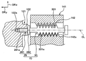
- 2 is an axial cross-sectional view of the connecting member 10 in FIG. 1 cut along a plane including the axis CL of the connecting member 10, and specifically, a cross section taken along the plane PL2 in FIG. FIG.
- the axial direction of the axial center CL is referred to as an axial center CL direction, and the axial center CL direction is the same as the Y direction DRy in this embodiment.
- a compressor 14 shown in FIG. 1 is a kind of auxiliary equipment for vehicles, and is an air conditioner compressor that compresses refrigerant of an air conditioner.
- the compressor 14 includes a compressor side connecting portion 141 as the other connection target portion connected by the connecting member 10, that is, a second connection target portion.
- the compressor side connecting portion 141 constitutes a part of the compressor 14.
- a plurality of compressor side connecting portions 141 are also provided.
- the compressor side connecting portion 141 includes a female screw portion 142 in which a female screw 142a is formed as a second connecting object screw portion.
- the screw hole in which the female screw 142a is formed is a through hole penetrating in the Y direction DRy.
- the axis of the female screw 142 a coincides with the axis CL of the connecting member 10.
- auxiliary equipment include an audio device, a head ride, a navigation device, and an air conditioner.
- a plurality of connecting members 10 are provided, and the plurality of connecting members 10 connect each of the engine side connecting portion 121 and each of the compressor side connecting portion 141.
- the connecting member 10 is used for all the connecting portions of the compressor 14 to the engine 12.
- the connecting member 10 is for connecting the engine side connecting portion 121 and the compressor side connecting portion 141, and includes a collar member 20 and a fastening bolt 22.
- the collar member 20 is formed in a cylindrical shape having a through hole 20a penetrating in the Y direction DRy.
- the collar member 20 has a male screw portion 201 as a connecting member screw portion on the outer peripheral side of the collar member 20.
- the male screw portion 201 is screwed into the female screw portion 142 of the compressor side connecting portion 141.
- the external thread 201a formed in the external thread part 201 has the same screw pitch as the internal thread 142a which meshes with it.
- the collar member 20 has one end face 202 at one end in the axial direction of the collar member 20, that is, the axial center CL direction, and the other end face 203 at the other end in the axial center CL direction.
- the one end face 202 is pressed by the bolt head 223 toward the engine side connecting portion 121 in the axial center CL direction, and the other end face 203 is pressed by the engine side connecting portion 121 toward the bolt head 223 side in the axial center CL direction.
- the collar member 20 is sandwiched between the engine side connecting portion 121 and the bolt head portion 223, and thereby fixed to the engine side connecting portion 121.
- the fastening bolt 22 is a hexagon bolt, and the axial center of the fastening bolt 22 coincides with the axial center CL of the connecting member 10.
- the fastening bolt 22 includes a bolt shaft portion 221, a male screw portion 222 as a fixing screw portion, and a bolt head portion 223.
- the bolt shaft portion 221 is a cylindrical portion, and is inserted through the through hole 20 a of the collar member 20.
- the male screw portion 222 of the fastening bolt 22 is a portion extending from the bolt shaft portion 221 to one of the axial directions of the bolt shaft portion 221, that is, one of the connecting member 10 in the axial center CL direction. Is formed with a male screw 222a.
- the male screw portion 222 is screwed into the female screw portion 122 of the engine side connecting portion 121 until the fastening bolt 22 is fixed to the engine side connecting portion 121.
- the fastening bolt 22 is configured such that the male threaded portion 222 of the fastening bolt 22 is screwed into the female threaded portion 122 of the engine side connecting portion 121 and cannot be relatively rotated or displaced. It is fixed to the connecting part 121. In short, it is concluded. In this way, the fastening bolt 22 is a fixed portion that is fixed to the engine side connecting portion 121.
- the bolt head portion 223 is a portion provided on the other side of the connecting member 10 in the axial center CL direction with respect to the bolt shaft portion 221, that is, a portion provided on the side opposite to the male screw portion 222 side, and has a hexagonal shape. It is made.
- a tool such as a spanner is engaged with the bolt head 223 to rotate the fastening bolt 22.
- the bolt head 223 presses the collar member 20 toward the engine side connecting portion 121 in the Y direction DRy via the washer 24 in a state where the fastening bolt 22 is fastened to the engine side connecting portion 121.
- the collar member 20 is sandwiched between the engine side connecting portion 121.
- the axis of the collar member 20 is the axis of the fastening bolt 22, that is, the connecting member 10. It coincides with or substantially coincides with the axis CL. Therefore, the male screw portion 222 of the fastening bolt 22 is disposed coaxially with the male screw portion 201 of the collar member 20.
- coaxial means not only perfect coaxial but also substantially coaxial.
- the male screw portion 201 of the collar member 20 is fastened to the engine side connecting portion 121 by the fastening bolt 22, so that the engine side It is fixed to the connecting part 121.
- the fastening bolt 22 is fastened and fixed to the engine side connecting portion 121, thereby fixing the male screw portion 201 of the collar member 20 to the engine side connecting portion 121.
- the male screw portion 201 of the collar member 20 is screwed to the female screw portion 142 of the compressor side connecting portion 141 and is relatively Rotation and relative displacement are held in a free state.
- the state in which the relative rotation and the relative displacement are free refers to a state in which the male screw portion 201 and the female screw portion 142 are screwed together. Further, since the male screw portion 201 is not fastened to the female screw portion 142, the state where the relative rotation and relative displacement are free is the male screw portion 201. Has a slight play in the direction other than the rotational direction around the axis CL with respect to the female screw portion 142.
- the male screw portion 201 can move in a slight range in any rotational direction and in any axial direction with respect to the female screw portion 142 by the slight amount of play.
- the relative displacement means relative movement in each of the axial directions DRx, DRy, DRz (see FIG. 1), and the relative displacement is not freely limited. Limited to the amount of play above.
- FIG. 3 is a diagram showing a comparative example with respect to the present embodiment, and corresponds to FIG.
- the compressor side connecting portion 141 is fastened to the engine side connecting portion 121 by the fastening bolts 22 and is integrally fixed at all connecting portions between the compressor 14 and the engine 12.
- FIG. 4 is a diagram showing the relationship between the excitation force applied to the compressor 14 and the displacement of the compressor 14 in the Y direction DRy.
- the excitation force and the displacement are in a proportional relationship as indicated by a broken line L1cp in FIG.
- the relationship between the excitation force and the displacement is as shown by a solid line L1pr in FIG. That is, there is a low-rigidity region where the rate of increase in the excitation force with respect to the increase in the displacement is in a range where the absolute value of the displacement is below a certain value. And if it remove
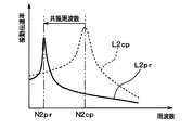
- FIG. 5 shows the relationship between the frequency of vibration applied to the compressor 14 and the vibration transmissibility, which is the ratio of the magnitude of vibration transmitted from the compressor 14 to the engine 12, in terms of the Y direction DRy.
- FIG. 5 shows the vibration transfer characteristic in the comparative example of FIG. 3, the vibration transfer characteristic is as indicated by a broken line L2cp, and the frequency N2cp is the resonance frequency.
- the vibration transfer characteristic is as indicated by the solid line L2pr, and the frequency N2pr is the resonance frequency.
- the engine 12 and the compressor 14 are integrally formed as in the comparative example of FIG. It is possible to lower the resonance frequency as compared with the fixed connection structure.
- the compressor 14 since the compressor 14 is attached to the engine 12 via the screw portions 142 and 201 having play as shown in FIG. 2, the compressor 14 is within the range of the play. This is because the compressor 14 is greatly displaced even when the applied load is small. That is, there is a low rigidity region (see FIG. 4) where the mounting rigidity of the compressor 14 is low.
- the resonance frequency is fr
- the rigidity of the mounting portion of the compressor 14 with respect to the engine 12 is k
- the mass of the compressor 14 is m
- the relationship between the resonance frequency fr and the rigidity k is expressed by the following formula F1. Is done.
- connection structure of this embodiment can make a resonant frequency low like FIG. 5, the vibration transmission in a high frequency area
- 4 and 5 are shown with respect to the Y direction DRy, the other axial directions DRx and DRz and all the rotation directions are the same as those in FIGS. 4 and 5.
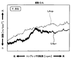
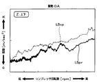
- FIGS. 6 to 8 are diagrams showing measurement results obtained by measuring the relationship between the rotation speed of the compressor 14 (compressor rotation speed) and the magnitude of vibration transmitted to the engine 12.
- 6 represents vibration in the X direction DRx
- FIG. 7 represents vibration in the Y direction DRy
- FIG. 8 represents vibration in the Z direction DRz.
- 6 to 8 are overall values (OA)
- the vertical axis of FIGS. 6 to 8 is a logarithmic scale.
- the measurement results in the comparative example of FIG. 3 are indicated by broken lines L3cp, L4cp, and L5cp
- the measurement results in the present embodiment are indicated by solid lines L3pr, L4pr, and L5pr.
- connection structure of this embodiment generally suppresses vibration transmission compared to the comparative example of FIG.
- the reason why vibration transmission is suppressed in this way is, for example, that vibrations are almost transmitted as long as they are within a slight play range between the male screw portion 201 of the collar member 20 and the female screw portion 142 of the compressor side connecting portion 141.
- the vibration is attenuated by the friction between the male screw portion 201 and the female screw portion 142.
- the fastening bolt 22 fixes the collar member 20 to the engine side connecting portion 121
- the male screw portion 201 of the collar member 20 is the female screw of the compressor side connecting portion 141. It is screwed to the portion 142 and is held in a state where relative rotation and relative displacement are free. Therefore, while the compressor 14 is supported with respect to the engine 12, the male screw portion 201 of the collar member 20 is in a direction other than the rotational direction in which the screws are screwed with the female screw portion 142 of the compressor side connecting portion 141. There is also a little play in the direction.
- the play allows the male screw portion 201 to move with respect to the female screw portion 142 in a slight range in any rotational direction and any axial direction. Therefore, the play makes it difficult for all axial and rotational vibrations to be transmitted between the engine side connecting portion 121 and the compressor side connecting portion 141. That is, as shown in FIGS. 6 to 8, vibration transmission between the compressor 14 and the engine 12 can be reduced.
- the fastening bolt 22 is configured such that the male threaded portion 222 of the fastening bolt 22 is screwed with the female threaded portion 122 of the engine side connecting portion 121 and cannot be relatively rotated or displaced.
- the collar member 20 is fixed to the engine side connecting portion 121 together with the fastening bolts 22. Therefore, the collar member 20 including the male screw portion 201 can be fixed to the engine side connecting portion 121 by a screw structure.
- the fastening bolt 22 is inserted into the through hole 20 a of the collar member 20, and the male screw portion 201 of the collar member 20 is fastened to the engine-side connecting portion 121 by the fastening bolt 22.
- the engine side connecting portion 121 is fixed. Therefore, the male screw portion 201 of the collar member 20 is screwed in advance with the female screw portion 142 of the compressor side connecting portion 141, and the collar member 20 is fixed to the engine side connecting portion 121 in the screwed state. Is possible. That is, it is possible to easily perform the work of completing the connection structure as shown in FIG.
- the connecting member 10 is used for all the connecting portions of the compressor 14 to the engine 12. That is, all of the connecting portions have a connecting structure as shown in FIG. Therefore, for example, the effect of reducing vibration transmission can be sufficiently obtained as compared with a case where a part of the plurality of connection portions has a connection structure as shown in FIG. (Second Embodiment)
- a second embodiment will be described. In the present embodiment, differences from the first embodiment will be mainly described. Further, the same or equivalent parts as those of the above-described embodiment will be described by omitting or simplifying them. The same applies to third and later embodiments described later.
- FIG. 9 is a cross-sectional view in the axial direction of the connecting member 10 in the present embodiment, and corresponds to FIG. As shown in FIG. 9, the connecting member 10 of the present embodiment is different from the first embodiment in that it is composed of one component.
- the connecting member 10 of the present embodiment is configured by forming the collar member 20 and the fastening bolt 22 of the first embodiment as a single component, and includes a fastening portion 28 and a screwing portion 30. . That is, the fastening portion 28 is configured integrally with the screwing portion 30.
- the fastening portion 28 and the screwing portion 30 are connected in series in the axial center CL direction of the connecting member 10, and the fastening portion 28 is disposed on the engine side connecting portion 121 side with respect to the screwing portion 30.
- the fastening portion 28 is a fixing portion that is directly fixed to the engine side connecting portion 121 of the connecting member 10, and has a male screw portion 281 as a fixing screw portion and a stopper 282.
- a male screw 281 a is formed on the outer periphery of the male screw portion 281, and the male screw portion 281 is screwed to the female screw portion 122 of the engine side connecting portion 121.
- the stopper 282 is provided at the proximal end of the male screw portion 281 and has a shape protruding in a radial shape in a hook shape.
- the stopper 282 abuts against the engine side connecting portion 121 in the direction of the axis CL when the male screw portion 281 is screwed into the female screw portion 122 of the engine side connecting portion 121. That is, the male screw portion 281 of the fastening portion 28 is screwed into the female screw portion 122 of the engine side connecting portion 121 until the stopper 282 hits the engine side connecting portion 121, so that the fastening portion 28 is connected to the engine side connecting portion 121. Fastened to the part 121.
- the fastening portion 28 is configured so that the male screw portion 281 of the fastening portion 28 is screwed into the female screw portion 122 of the engine side connecting portion 121 and the relative rotation and the relative displacement are disabled. It is fixed to the connecting part 121.
- the screwing portion 30 has a male screw portion 301 as a connecting member screw portion on the outer peripheral side of the screwing portion 30.
- the male screw portion 301 is screwed into the female screw portion 142 of the compressor side connecting portion 141, and the male screw 301a formed in the male screw portion 301 has the same screw pitch as the female screw 142a meshing therewith.
- the male screw portion 301 included in the screwing portion 30 is screwed into the female screw portion 142 of the compressor side connecting portion 141 and is held in a state where relative rotation and relative displacement can be freely performed.
- the male screw portion 281 of the fastening portion 28 is arranged coaxially with the male screw portion 301 of the screwing portion 30.
- the connecting member 10 of the present embodiment is also configured such that the male screw portion 301 as the connecting member screw portion is fastened with the fastening portion 28 as the fixing portion fastened to the engine side connecting portion 121. Thus, it is fixed to the engine side connecting portion 121.
- a configuration common to the first embodiment described above is included, and the effects produced from the common configuration can be obtained in the same manner as the first embodiment.
- the connecting member 10 of this embodiment is used in place of the connecting member 10 of the first embodiment, the characteristics relating to the vibrations of FIGS. 4 to 8 can be obtained as in the first embodiment.
- the fastening portion 28 as the fixing portion is configured integrally with the male screw portion 301 as the connecting member screw portion, so that the number of parts can be reduced as compared with the first embodiment. It is possible.
- a third embodiment will be described. In the present embodiment, differences from the first embodiment will be mainly described.
- FIG. 10 is a sectional view in the axial direction of the connecting member 10 in the present embodiment, and corresponds to FIG. As shown in FIG. 10, in this embodiment, the external thread part 201 of the collar member 20 differs from 1st Embodiment.
- the male screw portion 201 of the collar member 20 has a portion where the male screw 201a is not formed. That is, the male screw portion 201 includes a first screw region 205 in which the male screw 201a is formed, an intermediate region 206 in which the male screw 201a is not formed, and a second screw region 207 in which the male screw 201a is formed.
- the first screw region 205, the intermediate region 206, and the second screw region 207 are provided in order from the engine side connecting part 121 side in the axial center CL direction of the connecting member 10.
- a screw having a distance Ly between one screw thread 205 a in the first screw region 205 and another screw thread 207 a in the second screw region 207 is the thread gap interval Ly.
- the thread gap interval Ly is the gap between one screw trough 142b of the female screw portion 142 into which the one screw thread 205a fits and another screw trough 142c into the female screw portion 142 into which the other screw thread 207a fits. Is different. However, although the thread interval Ly differs with respect to the thread valley interval as described above, the difference between the intervals is slight, and the male screw portion 201 of the collar member 20 is the female screw of the compressor side connecting portion 141.
- the play between the male screw portion 201 and the female screw portion 142 is smaller than that in the first embodiment.
- the thread interval Ly is determined by the following formula F2.
- a configuration common to the first embodiment described above is included, and the effects produced from the common configuration can be obtained in the same manner as the first embodiment.
- the connecting member 10 of this embodiment is used in place of the connecting member 10 of the first embodiment, the characteristics relating to the vibrations of FIGS. 4 to 8 can be obtained as in the first embodiment.
- the compressor 14 is supported by the engine 12 in the first embodiment. It is possible to make it stronger as compared with the connection structure of the form.
- the mounting rigidity of the compressor 14 with respect to the engine 12 can be changed according to the magnitude of the shift amount ⁇ included in the formula F2.
- the axial sectional view of the connecting member 10 in this embodiment is the same as that in the first embodiment, that is, FIG.
- the screw pitch of the male screw portion 201 of the collar member 20 is different from the screw pitch of the female screw portion 142 of the compressor side connecting portion 141. This is different from the first embodiment.
- the screw pitch of the female screw portion 142 is the same regardless of the position in the Y direction DRy, but the screw pitch of the male screw portion 201 is different depending on the position in the Y direction DRy.
- the difference in screw pitch between the female screw portion 142 of the compressor side connecting portion 141 and the male screw portion 201 of the collar member 20 is slight, and the male screw portion 201 is screwed with respect to the female screw portion 142.
- the relative rotation and the relative displacement are maintained in a free state. That is, in the present embodiment, the play between the male screw portion 201 and the female screw portion 142 is smaller than that in the first embodiment.
- the thread pitch Pc (see FIG. 2) of the male thread portion 201 of the collar member 20 is determined by the following formula F3.
- Pc P0 ⁇ AM ⁇ XM NM (F3)
- P0 is a fixed pitch of the female screw 142a
- AM and NM are experimentally determined constants
- XM is from a predetermined reference position X0 in the Y direction DRy (see FIG. 2). Is the distance.
- the reference position X0 is, for example, one end of the male screw portion 201 on the engine side connecting portion 121 side.
- the constant AM and the constant NM are experimentally determined so that play that is not excessive or insufficient for reducing vibration transmission occurs between the male screw portion 201 and the female screw portion 142.
- the screw pitch Pc is determined based on the above formula F3
- the play between the male screw portion 201 and the female screw portion 142 decreases as the distance XM in the Y direction DRy from the reference position X0 increases.
- a configuration common to the first embodiment described above is included, and the effects produced from the common configuration can be obtained in the same manner as the first embodiment.
- the connecting member 10 of this embodiment is used in place of the connecting member 10 of the first embodiment, the characteristics relating to the vibrations of FIGS. 4 to 8 can be obtained as in the first embodiment.
- the screw pitch of the male screw portion 201 of the collar member 20 is different from the screw pitch of the female screw portion 142 of the compressor side connecting portion 141, so that the compressor 14 is supported by the engine 12.
- FIG. 11 is an axial sectional view cut along a plane including the axis CL of the connecting member 10 of the present embodiment.
- the thing which the connection member 10 connects differs from 2nd Embodiment.
- the connecting member 10 of the first embodiment connects the compressor 14 to the engine 12, but the connecting member 10 of this embodiment has a hose sleeve at the opening 401 of the heat exchanger 40 that forms part of the air conditioner. 36 are connected.
- the 1st connection object part which is one connection object part connected by the connection member 10 is the hose sleeve 36, and the 2nd connection which is the other connection object part connected by the connection member 10.
- the target part is the opening 401 of the heat exchanger 40.
- the axis CL of the connecting member 10 is also the axis of the opening 401 of the heat exchanger 40 and the hose sleeve 36, as shown in FIG.
- the hose sleeve 36 has a substantially cylindrical shape extending in the direction of the axis CL.
- the hose sleeve 36 includes one end 361 to which a hose 38 through which air-conditioning refrigerant flows is connected, the other end 362 connected to the opening 401 of the heat exchanger 40, one end 361 and the other end 362. And an intermediate portion 363 located between the two.
- the hose sleeve 36 is provided at the tip 381 of the hose 38, and the hose 38 is caulked and connected to one end 361 of the hose sleeve 36 by a caulking member 42.
- a communication port 401 a communicating with the hose sleeve 36 is formed inside the opening 401 that constitutes a part of the heat exchanger 40.
- the other end 362 of the hose sleeve 36 is inserted into the communication port 401a while having a slight play in the radial direction with respect to the communication port 401a.
- a gap between the opening 401 of the heat exchanger 40 and the other end 362 of the hose sleeve 36 is sealed by an O-ring 44.
- a male screw 36 a is formed on the outer periphery of the hose sleeve 36 from one end 361 to the intermediate portion 363. That is, the hose sleeve 36 includes an intermediate portion 363 as a first connection target screw portion in which a male screw 36a is formed.
- the opening 401 of the heat exchanger 40 has a male screw part 402 as a second connection target screw part on the outer periphery of the opening 401.
- a male screw 402 a is formed in the male screw portion 402.
- the connecting member 10 of the present embodiment includes a first nut 46 and a second nut 48 that are screwed into an intermediate portion 363 of the hose sleeve 36.
- the second nut 48 includes a fastening part 481 and a screwing part 482.
- the fastening portion 481 and the screwing portion 482 are connected in series in the axial center CL direction of the connecting member 10, and the fastening portion 481 is disposed closer to the one end 361 side of the hose sleeve 36 than the screwing portion 482.
- the screwing portion 482 is disposed on the outer peripheral side of the other end portion 362 of the hose sleeve 36.
- the fastening portion 481 of the second nut 48 is a fixing portion that is directly fixed to the intermediate portion 363 of the hose sleeve 36 in the second nut 48, and has a female screw portion 483 as a fixing screw portion.
- a female screw 483 a is formed on the inner periphery of the female screw portion 483, and the female screw portion 483 is screwed to the intermediate portion 363 of the hose sleeve 36.
- the first nut 46 together with the fastening portion 481 of the second nut 48 is also screwed into the intermediate portion 363 of the hose sleeve 36, and the second nut 48 and the first nut 46 are tightened so as to generate an axial force. Make up the nut.
- the fastening portion 481 of the second nut 48 is fixed to the intermediate portion 363 of the hose sleeve 36.
- the fastening portion 481 is connected to the hose sleeve 36 by engaging the female thread portion 483 of the fastening portion 481 with the intermediate portion 363 of the hose sleeve 36 and disabling relative rotation and relative displacement. It is fixed.
- the screwing portion 482 has a female screw portion 484 as a connecting member screw portion on the inner peripheral side of the screwing portion 482.
- the female screw portion 484 is screwed into the male screw portion 402 included in the opening 401 of the heat exchanger 40, and the female screw 484a formed in the female screw portion 484 has the same screw pitch as the male screw 402a meshing therewith. It has become.
- the female screw part 484 of the screwing part 482 is arranged coaxially with the female screw part 483 of the fastening part 481.
- the female screw portion 484 included in the screwing portion 482 is screwed into the male screw portion 402 of the opening 401 and is held in a state where relative rotation and relative displacement can be freely performed. .
- a configuration common to the second embodiment described above is included, and the effects produced from the common configuration can be obtained in the same manner as the second embodiment.
- the female screw portion 484 included in the screwing portion 482 is screwed into the male screw portion 402 of the opening 401 and is held in a state in which relative rotation and relative displacement can be freely performed.
- vibration transmission between the hose sleeve 36 and the opening 401 of the heat exchanger 40 can be reduced.
- the connecting member 10 connects the hose sleeve 36 to the heat exchanger 40, and the heat exchanger 40 is a device through which fluid (for example, refrigerant) flowing in the hose 38 circulates.
- the heat exchanger 40 may be replaced with the compressor 14 (see FIG. 1) or the like.
- connection structure using the connection member 10 includes the engine side connection part 121 as the first connection target part and the compressor side connection part 141 as the second connection target part.
- the present invention is applied to a connection structure that interconnects the members, the present invention may be applied to a connection structure that interconnects other members and the like. For example, it may be applied to the connection structure shown in FIG.
- FIG. 12 is a view showing an example in which the connection structure using the connection member 10 of the first embodiment is applied to the connection structure between the vehicle body 52 and the hose joint 54. It is the axial sectional view partially cut by the plane including.
- the body-side connecting portion 521 included in the vehicle body 52 is the first connection target portion
- the hose joint 54 that supports the hose 56 is the second connection target portion.
- the hose joint 54 includes a female screw portion 541 in which a female screw 541a is formed as a second connection target screw portion.
- the body side connection part 521 and the hose joint 54 are mutually connected by the connection member 10 similarly to the connection structure shown in FIG.
- the male screw portion 222 of the fastening bolt 22 is screwed into the female screw portion 522 of the body side connecting portion 521, and the collar member 20 is fastened and fixed to the body side connecting portion 521 by the fastening bolt 22. ing.
- the male screw portion 201 of the collar member 20 is in relation to the female screw portion 541 of the hose joint 54. It is screwed and held in a state where relative rotation and relative displacement are free.
- FIG. 12 only one connection location between the body side connection portion 521 and the hose joint 54 is displayed, but the body side connection portion 521 and the hose joint 54 are actually connected at a plurality of locations.
- FIG. 12 is a modification of the first embodiment, but any of the second to fourth embodiments described above can be combined with the embodiment shown in FIG.
- FIG. 13 is a diagram illustrating an example in which the second embodiment is combined with the embodiment illustrated in FIG. 12, and corresponds to FIG. 12.
- connection structure using the connection member 10 of the first embodiment may be applied to the connection structure shown in FIGS. 14 and 15 in addition to the connection structure of FIG.
- FIG. 14 is a view showing an example in which the connection structure using the connection member 10 of the first embodiment is applied to the connection structure between the pulley mounting portion 60 and the pulley 62 of the rotating machine 58. It is the axial sectional view cut
- FIG. 15 is a view taken in the direction of arrow XV in FIG. 14 and 15 is an auxiliary machine such as a water pump, a motor generator, a hydraulic pump for automatic transmission, or an alternator.
- a belt (not shown) is wound around the pulley 62, and the power of the vehicle engine is transmitted through the belt.
- the pulley mounting portion 60 is the first connection target portion
- the pulley 62 is the second connection target portion.
- the pulley 62 includes a female screw portion 621 in which a female screw 621a is formed as a second connection target screw portion.
- the pulley attachment part 60 and the pulley 62 are mutually connected by the connection member 10 similarly to the connection structure shown in FIG. There are four places where the pulley mounting portion 60 and the pulley 62 are connected, and the four connecting members 10 are arranged at equal intervals in the circumferential direction around the axis CLp of the pulley 62. Accordingly, the axial center CL of the connecting member 10 is parallel to the axial center CLp of the pulley 62.
- the male screw portion 222 of the fastening bolt 22 is screwed into the female screw portion 601 of the pulley mounting portion 60, and the collar member 20 is fastened and fixed to the pulley mounting portion 60 by the fastening bolt 22.
- the male screw portion 201 of the collar member 20 is screwed with the female screw portion 621 of the pulley 62 when the collar member 20 is fixed to the pulley mounting portion 60.
- the relative rotation and the relative displacement are freely held.
- FIGS. 14 and 15 is a modification of the first embodiment, but any of the second to fourth embodiments described above can be combined with the embodiment shown in FIGS. It is.
- FIG. 16 is a diagram showing an example in which the second embodiment is combined with the embodiment shown in FIGS. 14 and 15, and is an axial cross-sectional view corresponding to FIG. 14.
- FIG. 17 is a view taken along arrow XVII in FIG.
- a hexagonal hole 30a is formed at the axial end of the connecting member 10 opposite to the pulley mounting portion 60 side.
- a hexagon wrench is inserted into the hexagon hole 30a.
- the cap nut 66 is screwed onto the axial end portion of the connection member 10 to be attached, thereby closing the hexagonal hole 30a.
- the connecting member 10 is used for all of the connecting portions of the compressor 14 with respect to the engine 12, but the connecting member 10 is provided at one of the plurality of connecting portions. There is no problem even if the connecting structure using is used.
- the compressor 14 is attached to the engine 12, but may be attached to other places, for example, the vehicle body 52 as shown in FIG.
- each screw part 201, 301, 484 as a connection member screw part is fixed to each part 36, 60, 121, 521 as a 1st connection object part by bolting.
- it may be fixed by means other than bolting, such as welding.
Landscapes
- Engineering & Computer Science (AREA)
- General Engineering & Computer Science (AREA)
- Mechanical Engineering (AREA)
- Physics & Mathematics (AREA)
- Acoustics & Sound (AREA)
- Aviation & Aerospace Engineering (AREA)
- Connection Of Plates (AREA)
- Bolts, Nuts, And Washers (AREA)
- Vibration Prevention Devices (AREA)
Abstract
連結部材(10)は、第1連結対象部(36、60、121、521)と、雄ネジ(402a)または雌ネジ(142a、541a、621a)が形成された第2連結対象ネジ部(142、402、541、621)を有する第2連結対象部(54、62、141、401)とを連結する。連結部材は、第2連結対象ネジ部に対して螺合され相対回転および相対変位が自在な状態で保持される連結部材ネジ部(201、301、484)と、第1連結対象部に対して固定される固定部(22、28、481)とを備える。固定部は、第1連結対象部に対して固定されることで、連結部材ネジ部を第1連結対象部に対して固定する。
Description
本出願は、2014年7月22日に出願された日本出願番号2014-149091号に基づくもので、ここにその記載内容を援用する。
本開示は、二つの部材を相互に連結すると共に振動の伝達を低減するための連結部材、および、その二つの部材がその連結部材によって連結された連結構造に関するものである。
従来、この種の連結構造が、例えば特許文献1に記載された駆動車軸装置に採用されている。この特許文献1に記載された駆動車軸装置は、車内音の原因となる駆動系の振動の伝達を低減する。具体的に、この駆動車軸装置は、エンジン出力を車輪へ伝達するものであり、外輪軸とその外輪軸内に挿通された中心軸とを有し、外輪軸と中心軸とから成る二重軸構造を備えている。
その外輪軸と中心軸とは、回転方向において、スプラインを介して相対的に拘束され、そのスプラインは回転方向に遊びを有している。このような構造により、駆動車軸装置では、中心軸に発生する微小トルク変動が外輪軸へ伝達されないようになっている。
特許文献1に開示された連結構造は駆動車軸装置のものであるので、回転伝達系においては適用可能である。しかし、回転伝達系以外に適用することは困難である。従って、回転伝達系以外の用途を考慮すると、相互に連結される二つの部材間で振動の伝達を低減するため、特許文献1に開示された連結構造とは別の連結構造、またはその連結構造を成すための連結部材を案出する必要があった。
本開示は上記点に鑑みて、特許文献1に開示された連結構造とは別の構造をもって、相互に連結される二つの部材間での振動伝達を低減することが可能な連結部材およびその連結部材を含む連結構造を提供することを目的とする。
上記目的を達成するため、本開示の第1の態様における連結部材では、第1連結対象部と、雄ネジまたは雌ネジが形成された第2連結対象ネジ部を有する第2連結対象部とを連結するための連結部材であって、第2連結対象ネジ部に対して螺合され相対回転および相対変位が自在な状態で保持される連結部材ネジ部と、第1連結対象部に対して固定される固定部とを備え、その固定部は、第1連結対象部に対して固定されることで、連結部材ネジ部を第1連結対象部に対して固定することを特徴とする。
上述によれば、連結部材ネジ部は、第2連結対象ネジ部に対して螺合され相対回転および相対変位が自在な状態で保持されるので、連結部材ネジ部は第2連結対象ネジ部に対して、ネジの回転方向以外の方向へも僅かな遊びを有している。そのため、その遊びは、連結部材ネジ部が第2連結対象ネジ部に対し三次元的に僅かな範囲で軸方向移動および回転移動をすることを許容する。従って、その遊びによって第1連結対象部と第2連結対象部との間で振動が伝わり難くなる。すなわち、第1連結対象部と第2連結対象部との間における振動伝達を低減することが可能である。
上記目的を達成するため、本開示の第2の態様における連結構造では、第1連結対象部と、雄ネジまたは雌ネジが形成された第2連結対象ネジ部を有する第2連結対象部と、第1連結対象部と第2連結対象部とを連結するための連結部材とを含んでおり、その連結部材は、第2連結対象ネジ部に対して螺合され相対回転および相対変位が自在な状態で保持される連結部材ネジ部と、第1連結対象部に対して固定される固定部とを備え、その固定部は、第1連結対象部に対して固定されることで、連結部材ネジ部を第1連結対象部に対して固定していることを特徴とする。
上述によれば、上記第1の態様と同様に、連結部材ネジ部は、第2連結対象ネジ部に対して螺合され相対回転および相対変位が自在な状態で保持されるので、第1連結対象部と第2連結対象部との間における振動伝達を低減することが可能である。
本開示についての上記目的およびその他の目的、特徴や利点は、添付の図面を参照しながら下記の詳細な記述により、より明確になる。その図面は、
第1実施形態の連結部材によって相互に連結されたエンジンと圧縮機とを示した斜視図である。
図1における平面PL2で切断した断面をII方向から見た断面図である。
第1実施形態に対する比較例を示した図であって、図2に相当する図である。
第1実施形態において、圧縮機へ加わる加振力と圧縮機の変位との関係を示した図である。
第1実施形態において、圧縮機へ加えられる振動の周波数と、圧縮機からエンジンへ伝達される振動の割合である振動伝達率との関係すなわち振動伝達特性をY方向DRyについて示した図である。
第1実施形態において、圧縮機の回転数とエンジンへ伝達された振動の大きさとの関係を測定した測定結果を示す図であって、X方向DRxの振動を表した図である。
第1実施形態において、圧縮機の回転数とエンジンへ伝達された振動の大きさとの関係を測定した測定結果を示す図であって、Y方向DRyの振動を表した図である。
第1実施形態において、圧縮機の回転数とエンジンへ伝達された振動の大きさとの関係を測定した測定結果を示す図であって、Z方向DRzの振動を表した図である。
第2実施形態における連結部材の軸方向断面図であり、図2に相当する図である。
第3実施形態における連結部材の軸方向断面図であり、図2に相当する図である。
第5実施形態の連結部材の軸心CLを含む平面で切断した軸方向断面図である。
第1実施形態の連結部材を用いた連結構造を車両ボディーとホースジョイントとの間の連結構造に適用した一例を示す図であって、連結部材の軸心CLを含む平面で部分的に切断した軸方向断面図である。
図12に示す実施形態に第2実施形態を組み合わせた例を示す図であって、図12に相当する図である。
第1実施形態の連結部材を用いた連結構造を回転機のプーリ取付け部とプーリとの間の連結構造に適用した一例を示す図であって、そのプーリの軸心CLpを含む平面で切断した軸方向断面図である。
図14におけるXV矢視図である。
図14および図15に示す実施形態に第2実施形態を組み合わせた例を示す図であって、図14に相当する軸方向断面図である。
図16におけるXVII矢視図である。
以下、実施形態について図に基づいて説明する。なお、以下の各実施形態相互において、互いに同一もしくは均等である部分には、図中、同一符号を付してある。
(第1実施形態)
図1は、本実施形態の連結部材10によって相互に連結されたエンジン12と圧縮機14とを示した斜視図である。図1では、矢印DRxは、圧縮機14の前後方向であるX方向DRxを示し、矢印DRyは、圧縮機14の左右方向であるY方向DRyを示し、矢印DRzは、圧縮機14の上下方向であるZ方向DRzを示している。そのX、Y、Z方向DRx、DRy、DRzは相互に直交する方向である。また、連結部材10は複数設けられ、エンジン12と圧縮機14とを複数の連結箇所それぞれで互いに連結しており、図1ではその連結部材10が設けられている箇所がハッチングで示されている。具体的に、連結部材10が設けられている箇所は3箇所である。
(第1実施形態)
図1は、本実施形態の連結部材10によって相互に連結されたエンジン12と圧縮機14とを示した斜視図である。図1では、矢印DRxは、圧縮機14の前後方向であるX方向DRxを示し、矢印DRyは、圧縮機14の左右方向であるY方向DRyを示し、矢印DRzは、圧縮機14の上下方向であるZ方向DRzを示している。そのX、Y、Z方向DRx、DRy、DRzは相互に直交する方向である。また、連結部材10は複数設けられ、エンジン12と圧縮機14とを複数の連結箇所それぞれで互いに連結しており、図1ではその連結部材10が設けられている箇所がハッチングで示されている。具体的に、連結部材10が設けられている箇所は3箇所である。
エンジン12は一般的な車両用エンジンであり、連結部材10によって連結される一方の連結対象部すなわち第1連結対象部としてのエンジン側連結部121を備えている。言い換えれば、そのエンジン側連結部121は、エンジン12の一部を構成している。また、図1に示すように圧縮機14はエンジン12に対して複数箇所で連結されているので、エンジン側連結部121は複数設けられている。詳細に言えば3箇所に設けられている。
具体的にエンジン側連結部121は、図2に示すように、第1連結対象ネジ部として、雌ネジ122aが形成された雌ネジ部122を含んでいる。その雌ネジ122aが形成されたネジ穴は、Y方向DRyにおいて圧縮機14側に開放された止まり穴となっている。また、その雌ネジ122aの軸心は連結部材10の軸心CLと一致している。図2は、図1において連結部材10を、連結部材10の軸心CLを含む平面で切断した軸方向断面図であり、具体的には図1における平面PL2で切断した断面をII方向から見た断面図である。なお、上記軸心CLの軸方向を軸心CL方向と呼ぶものとし、その軸心CL方向は、本実施形態ではY方向DRyと同じである。
図1に示す圧縮機14は車両用の補機の一種であり、エアコンの冷媒を圧縮するエアコンコンプレッサである。圧縮機14は、連結部材10によって連結される他方の連結対象部すなわち第2連結対象部としての圧縮機側連結部141を備えている。言い換えれば、その圧縮機側連結部141は、圧縮機14の一部を構成している。また、上記のエンジン側連結部121と同様に、圧縮機側連結部141も複数設けられている。
具体的には図2に示すように、圧縮機側連結部141は、第2連結対象ネジ部として、雌ネジ142aが形成された雌ネジ部142を含んでいる。その雌ネジ142aが形成されたネジ穴は、Y方向DRyに貫通した貫通孔となっている。また、その雌ネジ142aの軸心は連結部材10の軸心CLと一致している。なお、車両用の補機とは、車両の走行に直接には関係ないが、間接的に走行を補助するための装置の総称をいう。補機の例としては、オーディオ装置、ヘッドライド、ナビゲーション装置、空調装置等がある。
図1および図2に示すように連結部材10は複数設けられ、その複数の連結部材10はそれぞれ、エンジン側連結部121の各々と圧縮機側連結部141の各々とを連結している。そして、連結部材10は、エンジン12に対する圧縮機14の連結箇所の全てに用いられている。
図2に示すように、連結部材10は、エンジン側連結部121と圧縮機側連結部141とを連結するためのものであり、カラー部材20と締結ボルト22とから構成されている。そのカラー部材20は、Y方向DRyに貫通した貫通孔20aを有する筒状に形成されている。そして、カラー部材20は、連結部材ネジ部としての雄ネジ部201を、カラー部材20の外周側に有している。その雄ネジ部201は、圧縮機側連結部141の雌ネジ部142に螺合されている。そして、その雄ネジ部201に形成されている雄ネジ201aは、それに噛み合う雌ネジ142aと同じネジピッチになっている。
また、カラー部材20は、カラー部材20の軸方向すなわち軸心CL方向の一端に一端面202を有すると共に、軸心CL方向の他端に他端面203を有している。その一端面202はボルト頭部223によって軸心CL方向のエンジン側連結部121側へ押圧され、他端面203はエンジン側連結部121によって軸心CL方向のボルト頭部223側へ押圧されている。すなわち、カラー部材20は、エンジン側連結部121とボルト頭部223との間に挟持され、それによってエンジン側連結部121に固定されている。
締結ボルト22は六角ボルトであり、締結ボルト22の軸心は連結部材10の軸心CLと一致している。締結ボルト22は、ボルト軸部221と、固定用ネジ部としての雄ネジ部222と、ボルト頭部223とから構成されている。ボルト軸部221は円柱状の部位であり、カラー部材20の貫通孔20aに挿通されている。
締結ボルト22の雄ネジ部222は、ボルト軸部221からボルト軸部221の軸方向の一方すなわち連結部材10の軸心CL方向の一方に延設された部位であり、雄ネジ部222の外周には雄ネジ222aが形成されている。そして、この雄ネジ部222は、締結ボルト22がエンジン側連結部121に対して固定されるまで、エンジン側連結部121の雌ネジ部122に螺合されている。詳しく言えば、締結ボルト22は、その締結ボルト22の雄ネジ部222がエンジン側連結部121の雌ネジ部122に対し螺合され且つ相対回転および相対変位が不能とされることにより、エンジン側連結部121に対して固定されている。要するに締結されている。このように、締結ボルト22は、エンジン側連結部121に対して固定される固定部となっている。
ボルト頭部223は、ボルト軸部221に対し連結部材10の軸心CL方向の他方に設けられた部位、すなわち雄ネジ部222側とは反対側に設けられた部位であり、六角形形状を成している。このボルト頭部223には、締結ボルト22を回転させるためにスパナ等の工具が係合される。図2に示すように、ボルト頭部223は、締結ボルト22がエンジン側連結部121に締結された状態では、座金24を介してカラー部材20をY方向DRyのエンジン側連結部121側へ押圧しつつ、エンジン側連結部121との間にカラー部材20を挟んでいる。
また、ボルト軸部221とカラー部材20の貫通孔20aとの間の径方向隙間は僅かなものとされているので、カラー部材20の軸心は、締結ボルト22の軸心すなわち連結部材10の軸心CLと一致し或いは略一致している。そのため、締結ボルト22の雄ネジ部222は、カラー部材20の雄ネジ部201と同軸状に配置されている。同軸状とは、完全な同軸だけでなく略同軸の状態を含む意味である。
このように構成された連結部材10では、図2に示すように、カラー部材20の雄ネジ部201は、カラー部材20が締結ボルト22によってエンジン側連結部121に締結されることにより、エンジン側連結部121に対して固定されている。言い換えれば、締結ボルト22は、エンジン側連結部121に対して締結され固定されることで、カラー部材20の雄ネジ部201をエンジン側連結部121に対して固定している。
そして、そのカラー部材20がエンジン側連結部121に対して固定されている状態において、カラー部材20の雄ネジ部201は、圧縮機側連結部141の雌ネジ部142に対して螺合され相対回転および相対変位が自在な状態で保持されている。この相対回転および相対変位が自在な状態とは、その雄ネジ部201と雌ネジ部142との螺合の状態を言うものである。また、この相対回転および相対変位が自在な状態とは雄ネジ部201が雌ネジ部142に締結されてはいない状態であるので、この相対回転および相対変位が自在な状態では、雄ネジ部201は雌ネジ部142に対して、軸心CLまわりの回転方向以外の方向にも僅かな遊びを有している。言い換えれば、雄ネジ部201は、その僅かな遊びの分、雌ネジ部142に対し、あらゆる回転方向およびあらゆる軸方向に僅かな範囲で移動可能となっている。例えば、上記相対変位とは各軸方向DRx、DRy、DRz(図1参照)それぞれへの相対移動を意味しており、上記相対変位が自在とは、無制限に相対変位が自在であるわけではなく、上記遊びの分だけに限られる。
次に、図3に示す比較例と本実施形態とを比較することにより、本実施形態の振動に関する特性を説明する。図3は、本実施形態に対する比較例を示した図であって、図2に相当する図である。図3の比較例では、圧縮機14とエンジン12との全ての連結箇所において、圧縮機側連結部141はエンジン側連結部121に対して締結ボルト22によって締結され一体的に固定されている。
先ず、図4から説明する。図4は、Y方向DRyにおいて、圧縮機14へ加わる加振力と圧縮機14の変位との関係を示した図である。図3の比較例では圧縮機14はエンジン12に一体的に固定されているので、図4の破線L1cpに示すように、加振力と変位とは比例関係となる。
その一方で、本実施形態では、上記加振力と変位との関係は図4の実線L1prに示すようになる。すなわち、変位の増大に対して加振力が増大する割合が小さい低剛性領域が、変位の絶対値が或る値以下となっている範囲に存在する。そして、その低剛性領域から外れると、変位の増大に対して加振力が増大する割合は、図3の比較例と同様になる。これは、カラー部材20の雄ネジ部201が圧縮機側連結部141の雌ネジ部142に対して螺合され相対回転および相対変位が自在な状態で保持され、その雄ネジ部201と雌ネジ部142との間に僅かな遊びがあるからである。
次に図5について説明する。図5は、圧縮機14へ加えられる振動の周波数と、圧縮機14からエンジン12へ伝達される振動の大きさの割合である振動伝達率との関係すなわち振動伝達特性をY方向DRyについて示した図である。図5に示すように、図3の比較例では振動伝達特性は破線L2cpのようになり、周波数N2cpが共振周波数となっている。一方で、本実施形態では振動伝達特性は実線L2prのようになり、周波数N2prが共振周波数となっている。
この破線L2cpと実線L2prとを比較すれば判るように、本実施形態におけるエンジン12と圧縮機14との連結構造では、図3の比較例のようにエンジン12と圧縮機14とを一体的に固定する連結構造と比較して、共振周波数を低くすることが可能である。これは、本実施形態では、圧縮機14が、図2に示すように遊びを有するネジ部142、201を介してエンジン12に取り付けられているため、その遊びの範囲内では、圧縮機14に加わる荷重が小さくても圧縮機14が大きく変位するからである。つまり、圧縮機14の取付け剛性が低い低剛性領域(図4参照)があるからである。
なお、共振周波数をfrとし、エンジン12に対する圧縮機14の取付け部分の剛性をkとし、圧縮機14の質量をmとすれば、その共振周波数frと剛性kとの関係は下記式F1によって表される。

そして、本実施形態の連結構造は図5のように共振周波数を低くすることが可能であるので、高周波領域における振動伝達を小さくすることができる。このことは、例えば、高周波領域における振動が問題となる場合にメリットがある。図4および図5は、Y方向DRyに関して示したものであるが、他の軸方向DRx、DRzおよび、あらゆる回転方向に関しても、図4および図5と同様になる。
次に図6~8について説明する。図6~8はそれぞれ、圧縮機14の回転数(コンプレッサ回転数)とエンジン12へ伝達された振動の大きさとの関係を測定した測定結果を示す図である。図6はX方向DRxの振動を表し、図7はY方向DRyの振動を表し、図8はZ方向DRzの振動を表している。また、図6~8に示す振動の大きさは何れもオーバーオール値(O.A.)であり、図6~8の縦軸は対数目盛になっている。また、図6~8において図3の比較例での測定結果は破線L3cp、L4cp、L5cpで示され、本実施形態での測定結果は実線L3pr、L4pr、L5prで示されている。
図6~8に示すように、何れの方向の振動であっても、本実施形態の連結構造は、図3の比較例に対して振動の伝達を概ね抑制している。このように振動伝達が抑制される理由としては、例えば、カラー部材20の雄ネジ部201と圧縮機側連結部141の雌ネジ部142との僅かな遊びの範囲内であれば振動が殆ど伝わらず、その雄ネジ部201と雌ネジ部142との摩擦によって振動が減衰させられるということが考えられる。
上述したように、本実施形態によれば、締結ボルト22はカラー部材20をエンジン側連結部121に対して固定し、カラー部材20の雄ネジ部201は、圧縮機側連結部141の雌ネジ部142に対して螺合され相対回転および相対変位が自在な状態で保持されている。従って、圧縮機14がエンジン12に対して支持されると共に、カラー部材20の雄ネジ部201は圧縮機側連結部141の雌ネジ部142に対して、ネジ同士が螺合する回転方向以外の方向にも僅かな遊びを有している。
そのため、その遊びは、雄ネジ部201が雌ネジ部142に対し、あらゆる回転方向およびあらゆる軸方向に僅かな範囲で移動することを許容する。従って、その遊びによってエンジン側連結部121と圧縮機側連結部141との間で、全ての軸方向および回転方向の振動が伝わり難くなる。すなわち、図6~8に示したように、圧縮機14とエンジン12との間における振動伝達を低減することが可能である。
また、本実施形態によれば、締結ボルト22は、締結ボルト22の雄ネジ部222が、エンジン側連結部121の雌ネジ部122に対し螺合され且つ相対回転および相対変位が不能とされることにより、エンジン側連結部121に対して固定され、カラー部材20はその締結ボルト22と共にエンジン側連結部121に対して固定される。従って、雄ネジ部201を含むカラー部材20をネジ構造によってエンジン側連結部121へ固定することが可能である。
また、本実施形態によれば、締結ボルト22は、カラー部材20の貫通孔20aに挿通され、カラー部材20の雄ネジ部201は、カラー部材20が締結ボルト22によってエンジン側連結部121に締結されることにより、そのエンジン側連結部121に対して固定される。従って、圧縮機側連結部141の雌ネジ部142にカラー部材20の雄ネジ部201を予め螺合しておき、その螺合した状態でカラー部材20をエンジン側連結部121へ固定することが可能である。すなわち、図2に示すような連結構造を完成させる作業を容易に行うことが可能である。
また、本実施形態によれば、エンジン12に対する圧縮機14の連結箇所の全てに連結部材10が用いられている。すなわち、その連結箇所の全てが、図2に示すような連結構造になっている。従って、例えば複数の連結箇所の一部が図3のような連結構造になっている場合と比較して、振動伝達を低減する効果を十分に得ることができる。
(第2実施形態)
次に、第2実施形態について説明する。本実施形態では、前述の第1実施形態と異なる点を主として説明する。また、前述の実施形態と同一または均等な部分については省略または簡略化して説明する。後述の第3実施形態以降でも同様である。
(第2実施形態)
次に、第2実施形態について説明する。本実施形態では、前述の第1実施形態と異なる点を主として説明する。また、前述の実施形態と同一または均等な部分については省略または簡略化して説明する。後述の第3実施形態以降でも同様である。
図9は、本実施形態における連結部材10の軸方向断面図であり、図2に相当する図である。図9に示すように、本実施形態の連結部材10は、1つの部品で構成されているという点で第1実施形態とは異なる。
具体的には、本実施形態の連結部材10は、第1実施形態のカラー部材20および締結ボルト22を一部品で構成したものであり、締結部28と螺合部30とから構成されている。すなわち、締結部28は螺合部30と一体的に構成されている。この締結部28と螺合部30とは連結部材10の軸心CL方向に直列につながっており、締結部28は螺合部30に対しエンジン側連結部121側に配置されている。
締結部28は、連結部材10のうちエンジン側連結部121へ直接固定される固定部であり、固定用ネジ部としての雄ネジ部281と、ストッパ282とを有している。その雄ネジ部281の外周には雄ネジ281aが形成されており、雄ネジ部281はエンジン側連結部121の雌ネジ部122に対して螺合されている。
ストッパ282は雄ネジ部281の基端に設けられ、径方向へ鍔状に張り出した形状をなしている。ストッパ282は、雄ネジ部281がエンジン側連結部121の雌ネジ部122に対して螺合されることでエンジン側連結部121へ軸心CL方向に突き当たる。すなわち、ストッパ282がエンジン側連結部121に対して突き当たるまで締結部28の雄ネジ部281がエンジン側連結部121の雌ネジ部122へ螺合されることで、締結部28は、エンジン側連結部121に対して締結されている。換言すれば、締結部28は、その締結部28の雄ネジ部281がエンジン側連結部121の雌ネジ部122に対し螺合され且つ相対回転および相対変位が不能とされることにより、エンジン側連結部121に対して固定されている。
螺合部30は、連結部材ネジ部としての雄ネジ部301を、螺合部30の外周側に有している。その雄ネジ部301は圧縮機側連結部141の雌ネジ部142に螺合され、その雄ネジ部301に形成されている雄ネジ301aは、それに噛み合う雌ネジ142aと同じネジピッチになっている。
そして、第1実施形態と同様に、螺合部30が有する雄ネジ部301は、圧縮機側連結部141の雌ネジ部142に対して螺合され相対回転および相対変位が自在な状態で保持されている。また、締結部28の雄ネジ部281は、螺合部30の雄ネジ部301と同軸状に配置されている。
本実施形態の連結部材10でも第1実施形態と同様に、連結部材ネジ部としての雄ネジ部301は、固定部としての締結部28がエンジン側連結部121に対して締結され固定されることで、エンジン側連結部121に対して固定されている。
本実施形態では、前述の第1実施形態と共通の構成が含まれており、その共通の構成から奏される効果を第1実施形態と同様に得ることができる。例えば、第1実施形態の連結部材10に替えて本実施形態の連結部材10が用いられても、第1実施形態と同様に、図4~8の振動に関する特性を得ることができる。
また、本実施形態によれば、固定部としての締結部28が連結部材ネジ部としての雄ネジ部301と一体に構成されているので、第1実施形態と比較して部品点数の削減を図ることが可能である。
(第3実施形態)
次に、第3実施形態について説明する。本実施形態では、前述の第1実施形態と異なる点を主として説明する。
(第3実施形態)
次に、第3実施形態について説明する。本実施形態では、前述の第1実施形態と異なる点を主として説明する。
図10は、本実施形態における連結部材10の軸方向断面図であり、図2に相当する図である。図10に示すように、本実施形態では、カラー部材20の雄ネジ部201が第1実施形態と異なっている。
具体的に本実施形態では、カラー部材20の雄ネジ部201はその一部分に雄ネジ201aが形成されていない部位を有している。すなわち、その雄ネジ部201は、雄ネジ201aが形成された第1ネジ領域205と、雄ネジ201aが形成されていない中間領域206と、雄ネジ201aが形成された第2ネジ領域207とを有している。その第1ネジ領域205、中間領域206、第2ネジ領域207は、連結部材10の軸心CL方向においてエンジン側連結部121側から順番に並んで設けられている。
また、カラー部材20の雄ネジ部201は、中間領域206では、圧縮機側連結部141の雌ネジ部142に螺合されないので、その雌ネジ部142との間に径方向隙間を形成している。
また、連結部材10の軸心CL方向すなわちY方向DRyにおいて、第1ネジ領域205の中の一のネジ山205aと第2ネジ領域207の中の他のネジ山207aとの間隔Lyであるネジ山間隔Lyが、その一のネジ山205aが嵌る雌ネジ部142の一のネジ谷142bと、他のネジ山207aが嵌る雌ネジ部142の他のネジ谷142cとの間隔であるネジ谷間隔に対して異なっている。但し、そのようにネジ山間隔Lyがネジ谷間隔に対して異なっているものの、その間隔相互の差は僅かであり、カラー部材20の雄ネジ部201は、圧縮機側連結部141の雌ネジ部142に対して螺合され相対回転および相対変位が自在な状態で保持されていることに変わりはない。すなわち、本実施形態では、第1実施形態と比較して、雄ネジ部201と雌ネジ部142との間の遊びが小さくなっている。
具体的に、上記ネジ山間隔Lyは下記式F2によって決定されている。
Ly=Py×Ny±α ・・・(F2)
上記式F2において、Pyは、一定値である雌ネジ142aのネジピッチであり、Nyは一のネジ谷142bから他のネジ谷142cまでのネジ谷数であって例えば図10では3であり、αは所定のずらし量である。そのずらし量αは、振動伝達を低減するのに過不足ない遊びが雄ネジ部201と雌ネジ部142との間に生じるように、実験的に定められる。上記式F2に基づいてネジ山間隔Lyが定められると、第1ネジ領域205と第2ネジ領域207とのそれぞれにおいて雄ネジ部201と雌ネジ部142との間の遊びが、第1実施形態と比較して小さくなる。
上記式F2において、Pyは、一定値である雌ネジ142aのネジピッチであり、Nyは一のネジ谷142bから他のネジ谷142cまでのネジ谷数であって例えば図10では3であり、αは所定のずらし量である。そのずらし量αは、振動伝達を低減するのに過不足ない遊びが雄ネジ部201と雌ネジ部142との間に生じるように、実験的に定められる。上記式F2に基づいてネジ山間隔Lyが定められると、第1ネジ領域205と第2ネジ領域207とのそれぞれにおいて雄ネジ部201と雌ネジ部142との間の遊びが、第1実施形態と比較して小さくなる。
本実施形態では、前述の第1実施形態と共通の構成が含まれており、その共通の構成から奏される効果を第1実施形態と同様に得ることができる。例えば、第1実施形態の連結部材10に替えて本実施形態の連結部材10が用いられても、第1実施形態と同様に、図4~8の振動に関する特性を得ることができる。
また、本実施形態によれば、図10のY方向DRyにおいて、ネジ山間隔Lyが、それに対応するネジ谷間隔に対して異なっているので、エンジン12に対する圧縮機14の支持を、第1実施形態の連結構造と比較して強固にすることが可能である。例えば上記式F2に含まれるずらし量αの大きさに応じて、エンジン12に対する圧縮機14の取付け剛性を変更することが可能である。
なお、本実施形態は第1実施形態に基づいた変形例であるが、本実施形態を前述の第2実施形態と組み合わせることも可能である。
(第4実施形態)
次に、第4実施形態について説明する。本実施形態では、前述の第1実施形態と異なる点を主として説明する。
(第4実施形態)
次に、第4実施形態について説明する。本実施形態では、前述の第1実施形態と異なる点を主として説明する。
本実施形態における連結部材10の軸方向断面図は第1実施形態と共通であり、すなわち図2である。本実施形態では、カラー部材20の雄ネジ部201のネジピッチは、圧縮機側連結部141の雌ネジ部142のネジピッチに対して異なっている。この点が第1実施形態と異なる。詳細には、雌ネジ部142のネジピッチはY方向DRyの位置に関わらず同じであるが、雄ネジ部201のネジピッチはY方向DRyの位置に応じて異なる大きさとなっている。
但し、その圧縮機側連結部141の雌ネジ部142とカラー部材20の雄ネジ部201との間のネジピッチの差異は僅かであり、その雄ネジ部201は、雌ネジ部142に対して螺合され相対回転および相対変位が自在な状態で保持されていることに変わりはない。すなわち、本実施形態では、第1実施形態と比較して、雄ネジ部201と雌ネジ部142との間の遊びが小さくなっている。
具体的には、カラー部材20の雄ネジ部201のネジピッチPc(図2参照)は下記式F3によって決定されている。
Pc=P0±AM×XMNM ・・・(F3)
上記式F3において、P0は、一定値である雌ネジ142aのネジピッチであり、AMおよびNMは実験的に定められる定数であり、XMはY方向DRyにおける所定の基準位置X0(図2参照)からの距離である。その基準位置X0は例えば雄ネジ部201のエンジン側連結部121側の一端とされる。また、定数AMおよび定数NMは、振動伝達を低減するのに過不足ない遊びが雄ネジ部201と雌ネジ部142との間に生じるように、実験的に定められる。上記式F3に基づいてネジピッチPcが定められると、基準位置X0からのY方向DRyの距離XMが大きくなるほど、雄ネジ部201と雌ネジ部142との間の遊びが小さくなる。
上記式F3において、P0は、一定値である雌ネジ142aのネジピッチであり、AMおよびNMは実験的に定められる定数であり、XMはY方向DRyにおける所定の基準位置X0(図2参照)からの距離である。その基準位置X0は例えば雄ネジ部201のエンジン側連結部121側の一端とされる。また、定数AMおよび定数NMは、振動伝達を低減するのに過不足ない遊びが雄ネジ部201と雌ネジ部142との間に生じるように、実験的に定められる。上記式F3に基づいてネジピッチPcが定められると、基準位置X0からのY方向DRyの距離XMが大きくなるほど、雄ネジ部201と雌ネジ部142との間の遊びが小さくなる。
本実施形態では、前述の第1実施形態と共通の構成が含まれており、その共通の構成から奏される効果を第1実施形態と同様に得ることができる。例えば、第1実施形態の連結部材10に替えて本実施形態の連結部材10が用いられても、第1実施形態と同様に、図4~8の振動に関する特性を得ることができる。
また、本実施形態によれば、カラー部材20の雄ネジ部201のネジピッチは、圧縮機側連結部141の雌ネジ部142のネジピッチに対して異なっているので、エンジン12に対する圧縮機14の支持を、第1実施形態の連結構造と比較して強固にすることが可能である。例えば上記式F3に含まれる定数AM、NMの大きさに応じて、エンジン12に対する圧縮機14の取付け剛性を変更することが可能である。
なお、本実施形態は第1実施形態に基づいた変形例であるが、本実施形態を前述の第2実施形態または第3実施形態と組み合わせることも可能である。
(第5実施形態)
次に、第5実施形態について説明する。本実施形態では、前述の第2実施形態と異なる点を主として説明する。図11は、本実施形態の連結部材10の軸心CLを含む平面で切断した軸方向断面図である。本実施形態では、連結部材10が連結する物が第2実施形態と異なっている。すなわち、第1実施形態の連結部材10はエンジン12に圧縮機14を連結するが、本実施形態の連結部材10は、空調装置の一部を構成する熱交換器40の開口部401にホーススリーブ36を連結する。
(第5実施形態)
次に、第5実施形態について説明する。本実施形態では、前述の第2実施形態と異なる点を主として説明する。図11は、本実施形態の連結部材10の軸心CLを含む平面で切断した軸方向断面図である。本実施形態では、連結部材10が連結する物が第2実施形態と異なっている。すなわち、第1実施形態の連結部材10はエンジン12に圧縮機14を連結するが、本実施形態の連結部材10は、空調装置の一部を構成する熱交換器40の開口部401にホーススリーブ36を連結する。
従って、本実施形態では、連結部材10によって連結される一方の連結対象部である第1連結対象部はホーススリーブ36であり、連結部材10によって連結される他方の連結対象部である第2連結対象部は熱交換器40の開口部401である。なお、連結部材10の軸心CLは、図11に示すように、熱交換器40の開口部401およびホーススリーブ36の軸心でもある。
ホーススリーブ36は、軸心CL方向に延びた略円筒形状を成している。ホーススリーブ36は、空調用の冷媒が流れるホース38が接続されている一端部361と、熱交換器40の開口部401に接続されている他端部362と、一端部361と他端部362との間に位置する中間部363とを備えている。ホーススリーブ36はホース38の先端381に設けられており、ホーススリーブ36の一端部361に、ホース38がカシメ部材42によってカシメ接続されている。
また、熱交換器40の一部を構成する開口部401の内側には、ホーススリーブ36に連通する連通口401aが形成されている。ホーススリーブ36の他端部362は、その連通口401aに対して径方向の僅かな遊びを有しつつ、その連通口401a内に挿入されている。熱交換器40の開口部401とホーススリーブ36の他端部362との間はOリング44によってシールされている。
また、ホーススリーブ36の一端部361から中間部363にわたって、その外周に雄ネジ36aが形成されている。すなわち、ホーススリーブ36は、雄ネジ36aが形成された第1連結対象ネジ部としての中間部363を備えている。
熱交換器40の開口部401は、その開口部401の外周に、第2連結対象ネジ部としての雄ネジ部402を有している。その雄ネジ部402には雄ネジ402aが形成されている。
図11に示すように、本実施形態の連結部材10は、ホーススリーブ36の中間部363に螺合されている第1ナット46および第2ナット48から構成されている。この第2ナット48は、締結部481と螺合部482とから構成されている。この締結部481と螺合部482とは連結部材10の軸心CL方向に直列につながっており、締結部481は螺合部482よりもホーススリーブ36の一端部361側に配置されている。そして、螺合部482は、ホーススリーブ36の他端部362の外周側に配置されている。
第2ナット48の締結部481は、第2ナット48のうちホーススリーブ36の中間部363へ直接固定される固定部であり、固定用ネジ部としての雌ネジ部483を有している。その雌ネジ部483の内周には雌ネジ483aが形成されており、雌ネジ部483はホーススリーブ36の中間部363に対して螺合されている。
そして、第2ナット48の締結部481と共に第1ナット46もホーススリーブ36の中間部363に螺合され、第2ナット48と第1ナット46とが相互に軸力を生じるように締め付けられるダブルナットを構成している。このダブルナットによって、第2ナット48の締結部481は、ホーススリーブ36の中間部363へ固定されている。言い換えれば、締結部481は、その締結部481の雌ネジ部483がホーススリーブ36の中間部363に対し螺合され且つ相対回転および相対変位が不能とされることにより、ホーススリーブ36に対して固定されている。
螺合部482は、連結部材ネジ部としての雌ネジ部484を、螺合部482の内周側に有している。その雌ネジ部484は、熱交換器40の開口部401に含まれる雄ネジ部402に螺合され、その雌ネジ部484に形成されている雌ネジ484aは、それに噛み合う雄ネジ402aと同じネジピッチになっている。螺合部482の雌ネジ部484は、締結部481の雌ネジ部483と同軸に配置されている。
そして、第2実施形態と同様に、螺合部482が有する雌ネジ部484は、開口部401の雄ネジ部402に対して螺合され相対回転および相対変位が自在な状態で保持されている。
本実施形態では、前述の第2実施形態と共通の構成が含まれており、その共通の構成から奏される効果を第2実施形態と同様に得ることができる。例えば、螺合部482が有する雌ネジ部484は、開口部401の雄ネジ部402に対して螺合され相対回転および相対変位が自在な状態で保持されているので、第2実施形態と同様にして、ホーススリーブ36と熱交換器40の開口部401との間における振動伝達を低減することが可能である。
上述の実施形態の変形例について述べる。(1)上述の第5実施形態において、連結部材10は、ホーススリーブ36を熱交換器40に連結するが、その熱交換器40は、ホース38内を流れる流体(例えば冷媒)が流通する機器であれば良く、熱交換器40が圧縮機14(図1参照)などに置き換わっても差し支えない。
(2)上述の第1実施形態において、連結部材10を用いた連結構造は、第1連結対象部としてのエンジン側連結部121と、第2連結対象部としての圧縮機側連結部141とを相互に連結する連結構造に適用されているが、それら以外の部材等を相互に連結する連結構造に適用されても差し支えない。例えば図12に示す連結構造に適用されても差し支えない。
図12は、第1実施形態の連結部材10を用いた連結構造を車両ボディー52とホースジョイント54との間の連結構造に適用した一例を示す図であって、連結部材10の軸心CLを含む平面で部分的に切断した軸方向断面図である。図12では、車両ボディー52に含まれるボディー側連結部521が第1連結対象部とされ、且つホース56を支持するホースジョイント54が第2連結対象部とされている。そのホースジョイント54は、雌ネジ541aが形成された雌ネジ部541を第2連結対象ネジ部として備えている。そして、図2に示す連結構造と同様に、そのボディー側連結部521とホースジョイント54とが連結部材10によって相互に連結されている。
また、図12では、締結ボルト22の雄ネジ部222はボディー側連結部521の雌ネジ部522に螺合され、カラー部材20は、締結ボルト22によって、ボディー側連結部521へ締結され固定されている。
また、第1実施形態と同様に、カラー部材20がボディー側連結部521に対して固定されている状態において、カラー部材20の雄ネジ部201は、ホースジョイント54の雌ネジ部541に対して螺合され相対回転および相対変位が自在な状態で保持されている。図12では、ボディー側連結部521とホースジョイント54との連結箇所が1箇所だけ表示されているが、実際に、ボディー側連結部521とホースジョイント54とは複数箇所で連結されている。
この図12に示す実施形態は第1実施形態の変形例であるが、図12に示す実施形態に前述の第2~第4実施形態の何れかを組み合わすことも可能である。例えば第2実施形態を組み合わせたものが図13に示されている。図13は、図12に示す実施形態に第2実施形態を組み合わせた例を示す図であって、図12に相当する図である。
また、第1実施形態の連結部材10を用いた連結構造は、図12の連結構造のほか、図14および図15に示す連結構造に適用されてもよい。その図14は、第1実施形態の連結部材10を用いた連結構造を回転機58のプーリ取付け部60とプーリ62との間の連結構造に適用した一例を示す図であって、そのプーリ62の軸心CLpを含む平面で切断した軸方向断面図である。図15は、図14におけるXV矢視図である。図14および図15に示す回転機58は、例えばウォータポンプ、モータジェネレータ、自動変速機用油圧ポンプ、またはオルタネータなどの補機である。プーリ62には、不図示のベルトが巻き付けられ、そのベルトを介して車両用エンジンの動力が伝達される。
図14および図15では、プーリ取付け部60が第1連結対象部とされ、且つプーリ62が第2連結対象部とされている。そのプーリ62は、雌ネジ621aが形成された雌ネジ部621を第2連結対象ネジ部として備えている。そして、図2に示す連結構造と同様に、そのプーリ取付け部60とプーリ62とが連結部材10によって相互に連結されている。プーリ取付け部60とプーリ62との連結箇所は4箇所であり、4つの連結部材10はそれぞれ、プーリ62の軸心CLpを中心とした周方向に等間隔に並んで配置されている。従って、連結部材10の軸心CLはプーリ62の軸心CLpと平行になっている。
また、締結ボルト22の雄ネジ部222はプーリ取付け部60の雌ネジ部601に螺合され、カラー部材20は、締結ボルト22によって、プーリ取付け部60へ締結され固定されている。
また、第1実施形態と同様に、カラー部材20がプーリ取付け部60に対して固定されている状態において、カラー部材20の雄ネジ部201は、プーリ62の雌ネジ部621に対して螺合され相対回転および相対変位が自在な状態で保持されている。
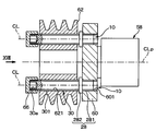
この図14および図15に示す実施形態は第1実施形態の変形例であるが、図14および図15に示す実施形態に前述の第2~第4実施形態の何れかを組み合わすことも可能である。例えば第2実施形態を組み合わせたものが図16および図17に示されている。図16は、図14および図15に示す実施形態に第2実施形態を組み合わせた例を示す図であって、図14に相当する軸方向断面図である。また、図17は、図16におけるXVII矢視図である。
なお、図16および図17に示す実施形態では、連結部材10のプーリ取付け部60側とは反対側の軸方向端部に六角穴30aが形成されている。この六角穴30aには六角レンチが挿入される。また、連結部材10の脱着防止のため、袋ナット66が連結部材10の上記軸方向端部に螺合されて装着され、それにより、六角穴30aが塞がれている。
(3)上述の第1~第4実施形態では、エンジン12に対する圧縮機14の連結箇所の全てに連結部材10が用いられているが、複数の連結箇所のうちの1箇所において、連結部材10が用いられた連結構造が適用されているだけであっても差し支えない。
(4)上述の第1~第4実施形態において、圧縮機14はエンジン12に取り付けられるが、それ以外の場所、例えば図12に示すような車両ボディー52に取り付けられても差し支えない。
(5)上述の各実施形態において、連結部材ネジ部としての各ネジ部201、301、484は、ボルト止めによって、第1連結対象部としての各部36、60、121、521に対して固定されているが、ボルト止め以外の他の手段たとえば溶接などによって固定されても差し支えない。
なお、本開示は上記した実施形態に限定されるものではなく、特許請求の範囲に記載した範囲内において適宜変更が可能である。また、上記各実施形態は、互いに無関係なものではなく、組み合わせが明らかに不可な場合を除き、適宜組み合わせが可能である。また、上記各実施形態において、実施形態を構成する要素は、特に必須であると明示した場合および原理的に明らかに必須であると考えられる場合等を除き、必ずしも必須のものではないことは言うまでもない。また、上記各実施形態において、実施形態の構成要素の個数、数値、量、範囲等の数値が言及されている場合、特に必須であると明示した場合および原理的に明らかに特定の数に限定される場合等を除き、その特定の数に限定されるものではない。また、上記各実施形態において、構成要素等の材質、形状、位置関係等に言及するときは、特に明示した場合および原理的に特定の材質、形状、位置関係等に限定される場合等を除き、その材質、形状、位置関係等に限定されるものではない。
本開示は、実施例に準拠して記述されたが、本開示は当該実施例や構造に限定されるものではないと理解される。本開示は、様々な変形例や均等範囲内の変形をも包含する。加えて、様々な組み合わせや形態、さらには、それらに一要素のみ、それ以上、あるいはそれ以下、を含む他の組み合わせや形態をも、本開示の範疇や思想範囲に入るものである。
Claims (11)
- 第1連結対象部(36、60、121、521)と、雄ネジ(402a)または雌ネジ(142a、541a、621a)が形成された第2連結対象ネジ部(142、402、541、621)を有する第2連結対象部(54、62、141、401)とを連結するための連結部材であって、
前記第2連結対象ネジ部に対して螺合され相対回転および相対変位が自在な状態で保持される連結部材ネジ部(201、301、484)と、
前記第1連結対象部に対して固定される固定部(22、28、481)とを備え、
該固定部は、前記第1連結対象部に対して固定されることで、前記連結部材ネジ部を前記第1連結対象部に対して固定することを特徴とする連結部材。 - 前記固定部は、前記連結部材ネジ部と同軸状に配置され雄ネジ(222a、281a)または雌ネジ(483a)が形成された固定用ネジ部(222、281、483)を有し、該固定用ネジ部が、前記第1連結対象部が有する第1連結対象ネジ部(122、363、522、601)に対し螺合され且つ相対回転および相対変位が不能とされることにより、前記第1連結対象部に対して固定されることを特徴とする請求項1に記載の連結部材。
- 貫通孔(20a)を有する筒状に形成され、外周側に設けられた雄ネジ部(201)を前記連結部材ネジ部として有しているカラー部材(20)を備え、
前記固定部は締結ボルト(22)であり、該締結ボルトは、前記貫通孔に挿通されるボルト軸部(221)と、該ボルト軸部から該ボルト軸部の軸方向の一方に延設され、前記第1連結対象部が有する第1連結対象ネジ部(122、522、601)に対し螺合される固定用ネジ部(222)とを有し、
前記連結部材ネジ部は、前記カラー部材が前記締結ボルトによって前記第1連結対象部に締結されることにより、該第1連結対象部に対して固定されることを特徴とする請求項1に記載の連結部材。 - 前記固定部(28)は、前記連結部材ネジ部(301)と同軸状に配置され雄ネジ(281a)が形成された固定用ネジ部(281)と、前記第1連結対象部(121)に突き当たるストッパ(282)とを有し、前記連結部材ネジ部と一体的に構成され、
前記固定用ネジ部は、前記第1連結対象部が有する第1連結対象ネジ部(122)に対して螺合され、
前記連結部材ネジ部は、前記固定部が前記第1連結対象部に締結されることにより、該第1連結対象部に対して固定されることを特徴とする請求項1に記載の連結部材。 - 前記第1連結対象部(121)は車両用エンジン(12)または車両ボディーの少なくとも一部を構成し、
前記第2連結対象部(141)は車両用補機(14)の少なくとも一部を構成することを特徴とする請求項1ないし4のいずれか1つに記載の連結部材。 - 前記第1連結対象部は、流体が流れるホース(38)の先端(381)に設けられたホーススリーブ(36)であり、
前記第2連結対象部は、前記流体が流通する機器(40)の一部を構成し前記ホーススリーブに連通する連通口(401a)が形成された開口部(401)であり、
前記第2連結対象ネジ部は、前記開口部の外周側に設けられた雄ネジ部(402)であり、
前記固定部(481)は、前記連結部材ネジ部(484)と同軸状に配置され雌ネジ(483a)が形成された固定用ネジ部(483)を有し、該固定用ネジ部が、前記第1連結対象部(36)が有する第1連結対象ネジ部(363)に対し螺合され且つ相対回転および相対変位が不能とされることにより、前記第1連結対象部に対して固定されることを特徴とする請求項1に記載の連結部材。 - 前記連結部材ネジ部(201)は、
該連結部材ネジ部の軸方向(DRy)において、ネジ(201a)が形成された第1ネジ領域(205)と、ネジが形成されていない中間領域(206)と、ネジが形成された第2ネジ領域(207)とを順に備えており、
前記中間領域では、前記第2連結対象ネジ部(142)に対して螺合されずに径方向隙間を形成することを特徴とする請求項1ないし6のいずれか1つに記載の連結部材。 - 前記軸方向において、前記第1ネジ領域の中の一のネジ山(205a)と前記第2ネジ領域の中の他のネジ山(207a)との間隔が、前記一のネジ山が嵌る前記第2連結対象ネジ部のネジ谷(142b)と前記他のネジ山が嵌る前記第2連結対象ネジ部のネジ谷(142c)との間隔に対して異なることを特徴とする請求項7に記載の連結部材。
- 前記連結部材ネジ部のネジピッチは前記第2連結対象ネジ部のネジピッチに対して異なることを特徴とする請求項1ないし8のいずれか1つに記載の連結部材。
- 第1連結対象部(36、60、121、521)と、
雄ネジ(402a)または雌ネジ(142a、541a、621a)が形成された第2連結対象ネジ部(142、402、541、621)を有する第2連結対象部(54、62、141、401)と、
前記第1連結対象部と前記第2連結対象部とを連結するための連結部材(10)とを含んでおり、
該連結部材は、前記第2連結対象ネジ部に対して螺合され相対回転および相対変位が自在な状態で保持される連結部材ネジ部(201、301、484)と、前記第1連結対象部に対して固定される固定部(22、28、481)とを備え、
該固定部は、前記第1連結対象部に対して固定されることで、前記連結部材ネジ部を前記第1連結対象部に対して固定していることを特徴とする連結構造。 - 前記第1連結対象部(121)は、車両用エンジン(12)または車両ボディーの一部を構成し且つ複数設けられ、
前記第2連結対象部(141)は車両用補機(14)の一部を構成し且つ複数設けられ、
前記連結部材は複数設けられ、該複数の連結部材はそれぞれ、前記第1連結対象部の各々と前記第2連結対象部の各々とを連結し、
前記車両用エンジンまたは車両ボディーに対する前記車両用補機の連結箇所の全てに前記連結部材が用いられていることを特徴とする請求項10に記載の連結構造。
Applications Claiming Priority (2)
| Application Number | Priority Date | Filing Date | Title |
|---|---|---|---|
| JP2014-149091 | 2014-07-22 | ||
| JP2014149091A JP2016023734A (ja) | 2014-07-22 | 2014-07-22 | 連結部材およびその連結部材を含む連結構造 |
Publications (1)
| Publication Number | Publication Date |
|---|---|
| WO2016013192A1 true WO2016013192A1 (ja) | 2016-01-28 |
Family
ID=55162737
Family Applications (1)
| Application Number | Title | Priority Date | Filing Date |
|---|---|---|---|
| PCT/JP2015/003615 Ceased WO2016013192A1 (ja) | 2014-07-22 | 2015-07-17 | 連結部材およびその連結部材を含む連結構造 |
Country Status (2)
| Country | Link |
|---|---|
| JP (1) | JP2016023734A (ja) |
| WO (1) | WO2016013192A1 (ja) |
Cited By (1)
| Publication number | Priority date | Publication date | Assignee | Title |
|---|---|---|---|---|
| US10982567B2 (en) | 2019-02-21 | 2021-04-20 | Mitsubishi Power, Ltd. | Condensate and feedwater system of steam power plant and operation method for the same |
Families Citing this family (3)
| Publication number | Priority date | Publication date | Assignee | Title |
|---|---|---|---|---|
| CN106050868A (zh) * | 2016-08-22 | 2016-10-26 | 苏州市顺仪五金有限公司 | 一种组合螺丝 |
| EP3587833A4 (en) * | 2017-02-23 | 2020-04-08 | Mitsubishi Jidosha Kogyo Kabushiki Kaisha | FASTENING STRUCTURE |
| JP7145828B2 (ja) * | 2019-09-03 | 2022-10-03 | 本田技研工業株式会社 | ボルト締付装置 |
Citations (2)
| Publication number | Priority date | Publication date | Assignee | Title |
|---|---|---|---|---|
| JP2003347387A (ja) * | 2002-05-29 | 2003-12-05 | Shinko Electric Co Ltd | 取付位置調整装置及び取付位置調整方法 |
| JP2013241949A (ja) * | 2012-05-17 | 2013-12-05 | Isuzu Motors Ltd | 防振構造 |
-
2014
- 2014-07-22 JP JP2014149091A patent/JP2016023734A/ja active Pending
-
2015
- 2015-07-17 WO PCT/JP2015/003615 patent/WO2016013192A1/ja not_active Ceased
Patent Citations (2)
| Publication number | Priority date | Publication date | Assignee | Title |
|---|---|---|---|---|
| JP2003347387A (ja) * | 2002-05-29 | 2003-12-05 | Shinko Electric Co Ltd | 取付位置調整装置及び取付位置調整方法 |
| JP2013241949A (ja) * | 2012-05-17 | 2013-12-05 | Isuzu Motors Ltd | 防振構造 |
Cited By (1)
| Publication number | Priority date | Publication date | Assignee | Title |
|---|---|---|---|---|
| US10982567B2 (en) | 2019-02-21 | 2021-04-20 | Mitsubishi Power, Ltd. | Condensate and feedwater system of steam power plant and operation method for the same |
Also Published As
| Publication number | Publication date |
|---|---|
| JP2016023734A (ja) | 2016-02-08 |
Similar Documents
| Publication | Publication Date | Title |
|---|---|---|
| US7345469B2 (en) | Axle assembly with sensor mount | |
| JP5366938B2 (ja) | 伝動装置のジャーナルを駆動軸の駆動継手の継手本体に相対回動不能に結合するための装置 | |
| WO2016013192A1 (ja) | 連結部材およびその連結部材を含む連結構造 | |
| US7886863B2 (en) | Driveshaft assembly with torque sensor | |
| US20140321946A1 (en) | Nut and sleeve fastener | |
| US9982720B2 (en) | Rotating shaft coupling | |
| US10323692B2 (en) | Slip yoke assembly | |
| US20190126740A1 (en) | Vehicle in-wheel motor drive device | |
| GB2524830A (en) | A powertrain housing assembly | |
| KR20180067309A (ko) | 볼트 체결 장치 | |
| US1136557A (en) | Steering arm and post. | |
| JP3089849B2 (ja) | エンジンのバランサ装置 | |
| JP4617860B2 (ja) | 車両部品及びエンジンの試験装置 | |
| JP6533860B1 (ja) | 推進軸 | |
| WO2011077655A1 (ja) | ディファレンシャル装置 | |
| CN101417611A (zh) | 车辆动力系统中的扭转扰动解耦 | |
| EP1367278A1 (en) | Compression elastic coupling device | |
| KR101722146B1 (ko) | 플라이휠 하우징을 구비하는 연소 엔진 | |
| US11105378B2 (en) | Wheel drive unit for vehicle | |
| US10941846B2 (en) | Differential assembly having an overhanging ring gear | |
| KR102042795B1 (ko) | 휠 베어링과 등속조인트의 아웃트레이스 체결구조 | |
| CN220791837U (zh) | 车载取力用弹性传动轴及汽车底盘结构 | |
| JP7519942B2 (ja) | コンプレッサ | |
| US20210285501A1 (en) | A coupling assembly having angled fastener holes | |
| US9273734B2 (en) | Rotating torque transmission buffered shaft |
Legal Events
| Date | Code | Title | Description |
|---|---|---|---|
| 121 | Ep: the epo has been informed by wipo that ep was designated in this application |
Ref document number: 15824815 Country of ref document: EP Kind code of ref document: A1 |
|
| NENP | Non-entry into the national phase |
Ref country code: DE |
|
| 122 | Ep: pct application non-entry in european phase |
Ref document number: 15824815 Country of ref document: EP Kind code of ref document: A1 |