WO2016013072A1 - 放熱器 - Google Patents
放熱器 Download PDFInfo
- Publication number
- WO2016013072A1 WO2016013072A1 PCT/JP2014/069462 JP2014069462W WO2016013072A1 WO 2016013072 A1 WO2016013072 A1 WO 2016013072A1 JP 2014069462 W JP2014069462 W JP 2014069462W WO 2016013072 A1 WO2016013072 A1 WO 2016013072A1
- Authority
- WO
- WIPO (PCT)
- Prior art keywords
- heat
- heat pipe
- transfer plate
- bulging
- heat transfer
- Prior art date
- Legal status (The legal status is an assumption and is not a legal conclusion. Google has not performed a legal analysis and makes no representation as to the accuracy of the status listed.)
- Ceased
Links
Images


Classifications
-
- F—MECHANICAL ENGINEERING; LIGHTING; HEATING; WEAPONS; BLASTING
- F28—HEAT EXCHANGE IN GENERAL
- F28D—HEAT-EXCHANGE APPARATUS, NOT PROVIDED FOR IN ANOTHER SUBCLASS, IN WHICH THE HEAT-EXCHANGE MEDIA DO NOT COME INTO DIRECT CONTACT
- F28D15/00—Heat-exchange apparatus with the intermediate heat-transfer medium in closed tubes passing into or through the conduit walls ; Heat-exchange apparatus employing intermediate heat-transfer medium or bodies
- F28D15/02—Heat-exchange apparatus with the intermediate heat-transfer medium in closed tubes passing into or through the conduit walls ; Heat-exchange apparatus employing intermediate heat-transfer medium or bodies in which the medium condenses and evaporates, e.g. heat pipes
- F28D15/0275—Arrangements for coupling heat-pipes together or with other structures, e.g. with base blocks; Heat pipe cores
-
- F—MECHANICAL ENGINEERING; LIGHTING; HEATING; WEAPONS; BLASTING
- F28—HEAT EXCHANGE IN GENERAL
- F28D—HEAT-EXCHANGE APPARATUS, NOT PROVIDED FOR IN ANOTHER SUBCLASS, IN WHICH THE HEAT-EXCHANGE MEDIA DO NOT COME INTO DIRECT CONTACT
- F28D15/00—Heat-exchange apparatus with the intermediate heat-transfer medium in closed tubes passing into or through the conduit walls ; Heat-exchange apparatus employing intermediate heat-transfer medium or bodies
- F28D15/02—Heat-exchange apparatus with the intermediate heat-transfer medium in closed tubes passing into or through the conduit walls ; Heat-exchange apparatus employing intermediate heat-transfer medium or bodies in which the medium condenses and evaporates, e.g. heat pipes
- F28D15/0266—Heat-exchange apparatus with the intermediate heat-transfer medium in closed tubes passing into or through the conduit walls ; Heat-exchange apparatus employing intermediate heat-transfer medium or bodies in which the medium condenses and evaporates, e.g. heat pipes with separate evaporating and condensing chambers connected by at least one conduit; Loop-type heat pipes; with multiple or common evaporating or condensing chambers
-
- H—ELECTRICITY
- H10—SEMICONDUCTOR DEVICES; ELECTRIC SOLID-STATE DEVICES NOT OTHERWISE PROVIDED FOR
- H10W—GENERIC PACKAGES, INTERCONNECTIONS, CONNECTORS OR OTHER CONSTRUCTIONAL DETAILS OF DEVICES COVERED BY CLASS H10
- H10W40/00—Arrangements for thermal protection or thermal control
- H10W40/70—Fillings or auxiliary members in containers or in encapsulations for thermal protection or control
- H10W40/73—Fillings or auxiliary members in containers or in encapsulations for thermal protection or control for cooling by change of state
Definitions
- the present invention relates to a radiator using a heat pipe.
- Patent Document 1 discloses a technique in which one end of a heat pipe is flattened to increase the contact area between the heat transfer plate and the heat pipe.
- the length of the heat pipe is increased to increase the embedded length in the heat transfer plate, and a configuration in which the heat pipe is bent in an L shape or a U shape and embedded in the heat transfer plate.
- an object of the present invention is to provide a radiator that can suppress an increase in the thickness of a heat transfer plate and an increase in installation space.
- the invention according to claim 1 for solving the above-mentioned problems includes a heat pipe, a heat transfer plate provided at one end of the heat pipe, and a heat dissipating fin provided at the other end of the heat pipe.
- the heat pipe includes a straight portion and a bulge portion provided at one end of the straight portion, and the bulge portion is embedded in the heat transfer plate. It is a radiator.
- the contact area between the heat pipe and the heat transfer plate can be increased without increasing the thickness dimension of the heat transfer plate. Can be increased. That is, according to the radiator of the present invention, it is possible to improve the heat dissipation performance while suppressing an increase in the thickness of the heat transfer plate and an increase in installation space.
- the bulging portion has a disk shape that extends along a plane that intersects the axial direction of the linear portion. According to such a configuration, an increase in the thickness dimension of the heat transfer plate can be suppressed.
- the heat transfer plate includes a substrate portion having a concave portion that accommodates the bulging portion and a lid portion that covers the bulging portion, and a through hole is formed in the bottom surface of the concave portion, It is preferable that the straight part is inserted through the through hole. According to such a structure, the bulging part of a heat pipe can be embedded in a heat exchanger plate with an easy process.
- the lid portion is fixed to the substrate portion by friction stir welding. According to such a configuration, since the amount of heat generated during joining is small, deformation of the heat transfer plate and the heat pipe can be suppressed.
- the radiator according to the present invention it is possible to suppress an increase in the thickness of the heat transfer plate and an increase in installation space while improving the heat dissipation performance.
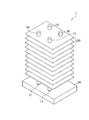
- the radiator 1 includes a heat pipe 10, a heat transfer plate 20, and a radiation fin 30.
- the heat pipe 10 transports heat by the phase change of evaporation / condensation of the working liquid sealed in the sealed space inside.
- the heat pipe 10 is made of a metal having high thermal conductivity such as copper.
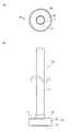
- the heat pipe 10 includes a straight portion 11 and a bulging portion 12 provided at one end of the straight portion 11.
- the straight part 11 constitutes a condensing part in which the evaporated working liquid is condensed. That is, the linear part 11 is a part which performs heat output.
- the straight portion 11 is connected to the upper portion of the bulging portion 12 and extends upward from the bulging portion 12.
- the straight portion 11 has a cylindrical shape with the upper end closed.
- the lower end of the straight part 11 is open and connected to the internal space of the bulging part 12.
- the heat pipe 10 is used with the bulging portion 12 on the bottom and the straight portion 11 on the top.
- the inner wall of the pipe is provided with a wire mesh (wick) or a fine groove (groove), and the inside has a capillary structure. Then, the heat pipe 10 can also be used in a sideways state.
- the linear part 11 of this embodiment becomes a cylindrical shape of the same diameter from a lower end to an upper end, it is not limited to this, It becomes a two-stage cylindrical shape which the upper end part was restrict
- the bulging portion 12 is located at the lower end of the heat pipe 10 and is embedded in the heat transfer plate 20.
- the bulging part 12 constitutes an evaporation part in which the working liquid evaporates. That is, the bulging part 12 is a part which inputs heat.
- the bulging portion 12 extends in a flat plate shape along a plane that intersects the axial direction of the linear portion 11 (in the present embodiment, a plane in which the axial direction of the linear portion 11 is the normal direction). In addition, the intersection angle of the bulging part 12 and the linear part 11 is not limited to a right angle.
- the straight portion 11 may stand upright with respect to the bulging portion 12.
- the bulging portion 12 has a cavity inside.
- the outer shape of the bulging portion 12 has a disk shape.
- the bulging portion 12 includes a main body portion 13 and a bottom plate portion 14.
- the main body 13 has a cylindrical shape with a top plate 15 and is open downward.
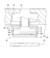
- the outer peripheral edge at the upper end of the main body 13 is chamfered. That is, the taper part 19a is formed in the intersection part of the upper surface and outer peripheral side surface of the top plate 15 (refer FIG. 5).
- an inclined surface 19b whose diameter is reduced toward the upper side is formed at the peripheral edge portion (the intersection of the lower surface of the top plate 15 and the inner peripheral side surface) of the upper end of the internal cavity of the bulging portion 12 (see FIG. 5). ).
- a through hole 16 is formed at the center of the top plate 15.
- a cylindrical upright portion 17 rising upward is formed on the top surface of the top plate 15.
- the inner peripheral surface of the rising portion 17 is continuously connected to the through hole 16, and the inner space portion of the rising portion 17 is communicated with the internal space of the bulging portion 12 through the through hole 16.
- the inner diameter dimension of the upright portion 17 is equal to the outer diameter dimension of the linear portion 11.
- a lower end portion of the linear portion 11 is fitted to the upright portion 17.
- the straight line part 11 is fixed to the main body part 13 so that the inside and the outside of the main body part 13 are in an airtight state, for example, by welding or brazing.
- An inclined portion 16 a that gradually increases in diameter downward is formed at the lower end portion of the through hole 16. This facilitates the flow of the working liquid vapor to the straight portion 11.
- the bottom plate portion 14 covers the opening at the lower end of the main body portion 13.
- the bottom plate portion 14 has a disk shape.
- a chamfering process is performed on the peripheral edge at the lower end of the bottom plate portion 14. That is, the intersection of the bottom surface and the outer peripheral side surface of the bottom plate portion 14 has a tapered shape.
- the outer diameter of the bottom plate portion 14 is larger than the inner diameter of the inner space of the heat transfer plate 20.
- An enlarged diameter portion 18 having an inner diameter dimension equivalent to the outer diameter dimension of the bottom plate portion 14 is formed at the lower end portion of the main body portion 13.
- the thickness dimension of the bottom plate portion 14 is slightly larger than the height dimension of the enlarged diameter portion 18.
- the bottom plate portion 14 is fitted to the enlarged diameter portion 18 with the tapered portion slightly protruding downward.
- the bottom plate part 14 is fixed to the main body part 13 so that the inside and the outside of the main body part 13 are in an airtight state, for example, by welding or brazing. Since the tapered portion of the bottom plate portion 14 slightly protrudes from the lower end of the main body portion 13, welding or brazing work is easy to perform.
- the bulging portion 12 has a disk shape, but may have another shape such as a rectangular or polygonal plate shape in plan view.
- the heat transfer plate 20 is a member that contacts a heat source (not shown) to be cooled and absorbs heat from the heat source.
- a heat source contacts the lower surface of the heat transfer plate 20.
- the heat transfer plate 20 is made of a lightweight and highly heat conductive metal such as an aluminum alloy.
- the heat transfer plate 20 has a rectangular shape in plan view.
- the heat transfer plate 20 of the present embodiment includes a substrate portion 21 and a lid portion 22.
- the substrate portion 21 includes a recess 23 for accommodating the bulging portion 12.
- the recess 23 is open downward.
- the recess 23 has a circular cross section, and the inner diameter of the recess 23 is equal to the outer diameter of the bulging portion 12.
- the depth dimension of the recess 23 is equivalent to the thickness dimension of the bulging portion 12.
- An inclined portion 27 that abuts against the tapered portion 19 a of the bulging portion 12 is formed at the upper end of the inner peripheral edge of the recess 23.
- the upper surface of the bulging portion 12 is in close contact with the bottom surface (upper surface) of the concave portion 23, and the outer peripheral surface of the bulging portion 12 is in close contact with the side surface of the concave portion 23.
- the tapered portion 19 a of the bulging portion 12 is in close contact with the inclined portion 27 of the recess 23. Thereby, the adhesiveness of the recessed part 23 and the bulging part 12 is improved.
- a through hole 24 reaching the upper surface of the heat transfer plate 20 is formed on the bottom surface (upper surface) of the recess 23.
- the straight portion 11 is inserted through the through hole 24.
- the through hole 24 has an inner diameter dimension equivalent to the outer diameter dimension of the rising portion 17 of the bulging portion 12.
- the upright portion 17 is also inserted into the through hole 24.
- an enlarged diameter recessed portion 25 into which the lid portion 22 is fitted is formed below the recessed portion 23.
- the inner diameter dimension of the enlarged diameter concave portion 25 is equal to the outer diameter dimension of the lid portion 22, and the depth dimension of the enlarged diameter concave portion 25 is equal to the thickness dimension of the lid portion 22.
- the lid portion 22 is fixed to the substrate portion 21 by friction stir welding. Specifically, while rotating a rotating tool (not shown), the rotating tool is moved along the abutting portion between the outer peripheral surface of the lid portion 22 and the inner peripheral surface of the enlarged-diameter concave portion 25, and is abutted by frictional heat between the rotating tool and the metal member.
- the metal members are solid-phase bonded by causing the metal of the part to flow plastically.
- the plasticized region 26 is formed along the abutting portion between the outer peripheral surface of the lid portion 22 and the inner peripheral surface of the enlarged diameter concave portion 25.
- the plasticized region 26 is formed over the entire circumference of the outer peripheral portion of the lid portion 22, and at least the start end and the end end overlap (see (c) of FIG. 2).
- heat pipes 10, 10 are attached to one heat transfer plate 20.
- the centers of the four heat pipes 10 are located on the diagonal line of the heat transfer plate 20 and are arranged so as to form a rectangular vertex.
- the number of heat pipes 10 is not limited to four, and may be smaller than four or larger than four. Further, the arrangement position of the heat pipe 10 is not limited to the above configuration.
- the radiation fin 30 is attached to the straight part 11 of the heat pipe 10.
- the radiating fins 30 are arranged along a plane whose normal direction is the axial direction of the straight portion 11.
- a plurality of radiating fins 30 are formed at intervals in the axial direction of the linear portion 11.
- a mounting hole 31 (see FIG. 1) through which the linear portion 11 passes is formed in the heat radiation fin 30.
- the inner diameter dimension of the mounting hole 31 is the same as the outer diameter dimension of the linear portion 11, and the radiating fins 30 are in circumferential contact over the entire outer periphery of the linear portion 11.
- the heat radiation fin 30 is fixed to the straight portion 11 by welding or brazing, for example.
- Four mounting holes 31, 31,... Are formed in one radiating fin 30, and four heat pipes 10, 10,.
- the heat pipe 10 is formed with the bulging portion 12 extending in a flat plate shape along a plane including an orthogonal line orthogonal to the axial direction of the linear portion 11 at one end portion of the heat pipe 10.
- An increase in the thickness dimension of the hot plate 20 (the length of the linear portion 11 in the axial direction) can be suppressed.
- the surface area of the bulging portion 12 can be efficiently increased as compared with a conventional one in which the heat pipe is simply bent (hereinafter referred to as “bent heat pipe”). That is, when trying to obtain the same surface area, the amount of increase in the length dimension in the plane direction may be smaller in the heat pipe 10 according to the present invention than in the bent heat pipe. Therefore, heat dissipation performance can be improved while suppressing an increase in the thickness of the heat transfer plate 30 and an increase in installation space.
- the bulging portion 12 has a disk shape, and further, an inclined surface 19b is formed at the peripheral edge of the upper end of the internal cavity of the bulging portion 12, so that the action generated in the bulging portion 12 is achieved.
- the liquid vapor easily flows to the straight portion 11. That is, since the peripheral edge of the internal cavity of the bulging portion 12 is annular, it does not stop and the steam is guided to the inner straight portion 11 by the inclined surface 19b.
- the surface area of the bulging portion 12 can be increased efficiently, the heat dissipation performance can be improved. Furthermore, an increase in the thickness dimension of the heat transfer plate 20 and an increase in the length dimension in the plane direction can be suppressed. Thereby, the weight of the entire radiator 1 can be suppressed, and the installation space for the radiator 1 can be reduced.
- the heat transfer plate 20 has a substrate portion 21 having a recess 23 and a lid portion 22, and a through hole 24 through which the linear portion 11 is inserted is formed on the bottom surface of the recess 23.
- the bulging portion 12 of the heat pipe 10 can be embedded in the heat transfer plate 20 by an easy process such as “attaching the heat pipe 10 to the recess 23 and fixing the lid portion 22 to the substrate portion 21”.
- the lid portion 22 is fixed to the substrate portion 21 by friction stir welding, the amount of heat generated during the joining is small. Therefore, thermal deformation of the heat transfer plate 20 and the heat pipe 10 can be suppressed. Furthermore, since the adhesiveness between the heat transfer plate 20 and the heat pipe 10 can be improved, high heat dissipation performance can be obtained.
- this invention is not limited to the said embodiment, A design change is possible suitably in the range which does not deviate from the meaning of this invention.
- the linear part 11 is being fixed to the center part of the bulging part 12, it is not limited to this.
- the straight line portion may be fixed at a position eccentric from the center of the bulging portion.
- you may fix a some linear part to the one bulging part.
- the bulging part 12 is exhibiting disk shape, it is not limited to this.
- Other shapes such as a spherical shape may be used as long as the outer shape of the straight portion 11 swells.
Landscapes
- Engineering & Computer Science (AREA)
- Life Sciences & Earth Sciences (AREA)
- Sustainable Development (AREA)
- Physics & Mathematics (AREA)
- Thermal Sciences (AREA)
- Mechanical Engineering (AREA)
- General Engineering & Computer Science (AREA)
- Cooling Or The Like Of Semiconductors Or Solid State Devices (AREA)
Abstract
伝熱板の厚さの増大と設置スペースの増大を抑制できる放熱器を提供する。ヒートパイプ(10)と、ヒートパイプ(10)の一端部に設けられる伝熱板(20)と、ヒートパイプ(10)の他端部に設けられる放熱フィン(30)とを備えており、ヒートパイプ(10)は、直線部(11)と、直線部(11)の一端に設けられた膨出部(12)とを備え、膨出部(12)は、伝熱板(20)の内部に埋設されていることを特徴とする。
Description
本発明は、ヒートパイプを用いた放熱器に関する。
近年、電子機器の高性能化に伴い、電子機器から発せられる熱量が増大している。電子機器の温度が高くなると十分な性能を発揮できなくなるため、電子機器の温度上昇を防止できる放熱器が要求されている。このような放熱器の一種として、ヒートパイプの一端を伝熱板に埋設し、ヒートパイプの他端部近傍に放熱フィンを設けた放熱器が知られている(たとえば特許文献1参照)。この放熱器では、十分な放熱性能を得るために、伝熱板とヒートパイプ間の伝熱効率を上げる必要がある。伝熱効率を上げるには、伝熱板とヒートパイプとの接触面積を大きくしなければならない。
特許文献1には、ヒートパイプの一端に扁平加工を施して、伝熱板とヒートパイプとの接触面積を大きくした技術が開示されている。また、ヒートパイプの長さを大きくして伝熱板への埋設長さを大きくする構成や、ヒートパイプをL字状やU字状に曲げて伝熱板に埋設する構成もあった。
特許文献1の構成やヒートパイプの長さを大きくする構成では、接触面積の増大に比例して伝熱板の厚さが大きくなってしまうため、放熱器の重量が大きくなり、また設置スペースが増大してしまう問題があった。ヒートパイプを曲げて伝熱板に埋設する構成では、伝熱板の厚さの増大は抑制できるものの、伝熱板の横寸法が大きくなってしまうため、前記と同様に、放熱器の重量が大きくなり、また設置スペースが増大してしまう問題があった。
本発明は、かかる問題に鑑みて、伝熱板の厚さの増大と設置スペースの増大を抑制できる放熱器を提供することを課題とする。
前記課題を解決するための請求の範囲第1項に係る発明は、ヒートパイプと、前記ヒートパイプの一端部に設けられる伝熱板と、前記ヒートパイプの他端部に設けられる放熱フィンとを備えており、前記ヒートパイプは、直線部と、前記直線部の一端に設けられた膨出部とを備え、前記膨出部は、前記伝熱板の内部に埋設されていることを特徴とする放熱器である。
このような構成の放熱器によれば、ヒートパイプの一端部に、膨出部を形成したので、伝熱板の厚さ寸法を増大させずとも、ヒートパイプと伝熱板との接触面積を増大させることができる。つまり、本発明の放熱器によれば、伝熱板の厚さの増大と設置スペースの増大を抑制しつつ、放熱性能を向上させることができる。
前記膨出部は、前記直線部の軸方向に交差する平面に沿って広がる円板形状を呈していることが好ましい。このような構成によれば、伝熱板の厚さ寸法の増大を抑制できる。
前記伝熱板は、前記膨出部を収容する凹部を備えた基板部と、前記膨出部を覆う蓋部とを備えており、前記凹部の底面には、貫通孔が形成されており、前記貫通孔に前記直線部が挿通されていることが好ましい。このような構成によれば、容易な工程で、ヒートパイプの膨出部を伝熱板に埋め込むことができる。
前記蓋部は、摩擦攪拌接合によって前記基板部に固定されていることが好ましい。このような構成によれば、接合時に発生する熱量が小さいので、伝熱板やヒートパイプの変形を抑制できる。
本発明に係る放熱器によれば、放熱性能を向上させつつ、伝熱板の厚さの増大と設置スペースの増大を抑制することができる。
本発明の実施形態に係る放熱器を、添付した図面を参照しながら詳細に説明する。図1乃至図3に示すように、放熱器1は、ヒートパイプ10と伝熱板20と放熱フィン30とを備えている。
ヒートパイプ10は、内部の密閉空間に封入された作動液体の蒸発・凝縮の相変化で熱を輸送するものである。ヒートパイプ10は、銅などの熱伝導率が高い金属からなる。図4にも示すように、ヒートパイプ10は、直線部11と、直線部11の一端に設けられた膨出部12とを備えている。
直線部11は、蒸発した作動液体が凝縮する凝縮部を構成している。つまり、直線部11は、熱出力を行う部分である。直線部11は、膨出部12の上部に接続されており、膨出部12から上方に延出している。直線部11は、上端が閉じられた円筒形状を呈している。直線部11の下端は開口しており、膨出部12の内部空間に繋がっている。ヒートパイプ10は、膨出部12を下側にして直線部11を上側にした状態で使用するが、パイプの内壁に金網(ウィック)または細かい溝(グルーブ)を設けて、内部を毛細管構造とすれば、ヒートパイプ10を横向きの状態で使用することもできる。なお、本実施形態の直線部11は、下端から上端まで同一径の円筒形状となっているが、これに限定されるものではなく、上端部が絞られて縮径した二段円筒形状となる場合もある。このような場合は、上端部にキャップ部材を被せて段差部分を隠すことがある。
膨出部12は、ヒートパイプ10の下端部に位置しており、伝熱板20に埋設されている。膨出部12は、作動液体が蒸発する蒸発部を構成している。つまり、膨出部12は、熱入力を行う部分である。膨出部12は、直線部11の軸方向に交差する平面(本実施形態では、直線部11の軸方向を法線方向とする平面)に沿って平板状に広がっている。なお、膨出部12と直線部11との交差角度は、直角に限定されるものではない。直線部11が膨出部12に対して傾斜して起立していてもよい。膨出部12は、内部に空洞を備えている。膨出部12の外形は円板形状を呈している。膨出部12は、本体部13と底板部14とを備えている。
図1および図5に示すように、本体部13は、天板15を備えた円筒形状を呈しており、下方に向かって開口している。本体部13の上端の外周縁部には、面取り加工が施されている。つまり、天板15の上面と外周側面の交差部分には、テーパ部19aが形成されている(図5参照)。一方、膨出部12の内部空洞の上端の周縁部(天板15の下面と内周側面の交差部分)には、上側に向かって縮径する傾斜面19bが形成されている(図5参照)。
図5に示すように、天板15の中心部には、貫通孔16が形成されている。天板15の上面には、上方に立ち上がる円筒状の立上部17が形成されている。立上部17の内周面は、貫通孔16に連続して繋がっており、立上部17の内空部は、貫通孔16を介して膨出部12の内部空間に連通している。立上部17の内径寸法は、直線部11の外径寸法と同等になっている。立上部17には、直線部11の下端部が嵌合されている。直線部11は、たとえば溶接またはろう付けなどによって、本体部13の内部と外部が気密状態となるように本体部13に固定されている。貫通孔16の下端部には、下方に向かって漸次拡径する傾斜部16aが形成されている。これによって、作動液体の蒸気が直線部11に流れやすくなっている。
底板部14は、本体部13の下端の開口部を覆っている。底板部14は円板形状を呈している。底板部14の下端の周縁部には、面取り加工が施されている。つまり、底板部14の底面と外周側面の交差部分は、テーパ形状を呈している。底板部14の外径寸法は、伝熱板20の内空部の内径寸法より大きい。本体部13の下端部には、底板部14の外径寸法と同等の内径寸法を備えた拡径部18が形成されている。底板部14の厚さ寸法は、拡径部18の高さ寸法より若干大きい。底板部14は、テーパ部が僅かに下方に突出した状態で拡径部18に嵌合されている。底板部14は、たとえば溶接またはろう付けなどによって、本体部13の内部と外部が気密状態となるように本体部13に固定されている。本体部13の下端から底板部14のテーパ部分が僅かに突出しているので、溶接またはろう付け作業が行い易い。
なお、本実施形態では、膨出部12が円板形状を呈しているが、たとえば平面視で矩形や多角形の板状形状など、他の形状であってもよい。
図1乃至図3に示すように、伝熱板20は、冷却対象である熱源(図示せず)に接触して、熱源から吸熱する部材である。伝熱板20の下面に熱源が当接する。伝熱板20は、アルミニウム合金などの軽量且つ熱伝導性の高い金属にて構成されている。伝熱板20は、平面視矩形形状を呈している。本実施形態の伝熱板20は、基板部21と蓋部22とを備えている。
図1および図5に示すように、基板部21は、膨出部12を収容する凹部23を備えている。凹部23は、下方に向かって開口している。凹部23は、断面円形を呈しており、凹部23の内径寸法は、膨出部12の外径寸法と同等である。凹部23の深さ寸法は、膨出部12の厚さ寸法と同等である。凹部23の内周縁部上端には、膨出部12のテーパ部19aに当接する傾斜部27が形成されている。凹部23の底面(上面)に膨出部12の上面が密着し、凹部23の側面に膨出部12の外周面が密着している。また、凹部23の内周上端では、凹部23の傾斜部27に膨出部12のテーパ部19aが密着している。これによって、凹部23と膨出部12の密着性が高められている。
凹部23の底面(上面)には、伝熱板20の上面に至る貫通孔24が形成されている。貫通孔24には、直線部11が挿通されている。貫通孔24は、膨出部12の立上部17の外径寸法と同等の内径寸法を備えている。なお、貫通孔24には、立上部17も挿通されている。
図5に示すように、凹部23の下側には、蓋部22が嵌まる拡径凹部25が形成されている。拡径凹部25の内径寸法は、蓋部22の外径寸法と同等であり、拡径凹部25の深さ寸法は、蓋部22の厚さ寸法と同等である。
図1および図2の(c)に示すように、蓋部22は、摩擦攪拌接合によって基板部21に固定されている。具体的には、図示しない回転ツールを回転させながら、蓋部22の外周面と拡径凹部25の内周面との突合部に沿って移動させ、回転ツールと金属部材との摩擦熱により突合部の金属を塑性流動させることで、金属部材同士を固相接合している。これによって、蓋部22の外周面と拡径凹部25の内周面との突合部に沿って、塑性化領域26が形成される。塑性化領域26は、蓋部22の外周部の全周に亘って形成されており、少なくとも始端と終端とが重複している(図2の(c)参照)。
図2および図3に示すように、本実施形態では、一の伝熱板20に4つのヒートパイプ10,10・・が取り付けられている。4つのヒートパイプ10の中心は、伝熱板20の対角線上に位置しており、且つ長方形の頂点を構成するように配置されている。なお、ヒートパイプ10の個数は4つに限定されるものではなく、4つより少数であってもよいし、4つより多数であってもよい。また、ヒートパイプ10の配置位置も前記構成に限定されるものではない。
図1にも示すように、放熱フィン30は、ヒートパイプ10の直線部11に取り付けられている。放熱フィン30は、直線部11の軸方向を法線方向とする平面に沿って配置されている。放熱フィン30は、直線部11の軸方向に間隔をあけて複数形成されている。放熱フィン30には、直線部11が貫通する取付孔31(図1参照)が形成されている。取付孔31の内径寸法は、直線部11の外径寸法と同等であり、直線部11の外周部全周に亘って放熱フィン30が周接している。放熱フィン30は、たとえば溶接またはろう付けなどによって、直線部11に固定されている。一枚の放熱フィン30には、4つの取付孔31,31・・が形成されており、4つのヒートパイプ10,10・・が固定されている。
前記構成の放熱器1によれば、ヒートパイプ10の一端部に、直線部11の軸方向に直交する直交線を含む平面に沿って平板状に広がる膨出部12を形成したことで、伝熱板20の厚さ寸法(直線部11の軸方向の長さ)の増大を抑制できる。さらに、ヒートパイプを単に曲げただけの従来のもの(以下「折曲形ヒートパイプ」という)と比較して、効率的に膨出部12の表面積を増大できる。つまり、同じ表面積を得ようとした場合に、平面方向への長さ寸法の増加量は、本発明に係るヒートパイプ10の方が折曲形ヒートパイプよりも小さくて済む。したがって、伝熱板30の厚さの増大と設置スペースの増大を抑制しつつ、放熱性能を向上させることができる。
また、膨出部12は、円板形状を呈しており、さらに、膨出部12の内部空洞の上端の周縁部に傾斜面19bが形成されているので、膨出部12内で発生した作用液体の蒸気が直線部11へと流れやすくなっている。つまり、膨出部12の内部空洞の周縁部は円環状なので行き止まることがなく、傾斜面19bによって、蒸気が内側の直線部11へと案内される。
以上のように、本発明によれば、効率的に膨出部12の表面積を増大することができるので、放熱性能を向上することができる。さらに、伝熱板20の厚さ寸法の増大と平面方向の長さ寸法の増大を抑制できる。これによって、放熱器1全体の重量化を抑制できるとともに、放熱器1の設置スペースを小さくできる。
また、伝熱板20は、凹部23を備えた基板部21と、蓋部22とを有しており、凹部23の底面には、直線部11が挿通する貫通孔24が形成されているので、「ヒートパイプ10を凹部23に装着して、蓋部22を基板部21に固定する」といった容易な工程で、ヒートパイプ10の膨出部12を伝熱板20に埋設することができる。
さらに、蓋部22が基板部21に摩擦攪拌接合によって固定されているので、接合時に発生する熱量が小さい。したがって、伝熱板20やヒートパイプ10の熱変形を抑制できる。さらには、伝熱板20とヒートパイプ10の密着性を高めることができるので、高い放熱性能を得ることができる。
以上、本発明を実施するための形態について説明したが、本発明は前記実施形態に限定されず、本発明の趣旨を逸脱しない範囲で適宜設計変更が可能である。たとえば、前記実施形態では、直線部11は膨出部12の中心部に固定されているが、これに限定されるものではない。直線部が膨出部の中心から偏心した位置に固定されていてもよい。また、一の膨出部に複数の直線部を固定してもよい。
また、前記実施形態では、膨出部12が円板形状を呈しているが、これに限定されるものではない。直線部11の外形よりも膨らんでいれば、たとえば球形状などの他の形状であってもよい。
1 放熱器
10 ヒートパイプ
11 直線部
12 膨出部
20 伝熱板
21 基板部
22 蓋部
23 凹部
24 貫通孔
30 放熱フィン
10 ヒートパイプ
11 直線部
12 膨出部
20 伝熱板
21 基板部
22 蓋部
23 凹部
24 貫通孔
30 放熱フィン
Claims (4)
- ヒートパイプと、前記ヒートパイプの一端部に設けられる伝熱板と、前記ヒートパイプの他端部に設けられる放熱フィンとを備えており、
前記ヒートパイプは、直線部と、前記直線部の一端に設けられた膨出部とを備え、
前記膨出部は、前記伝熱板の内部に埋設されている
ことを特徴とする放熱器。 - 前記膨出部は、前記直線部の軸方向に交差する平面に沿って広がる円板形状を呈している
ことを特徴とする請求の範囲第1項に記載の放熱器。 - 前記伝熱板は、前記膨出部を収容する凹部を備えた基板部と、前記膨出部を覆う蓋部とを備えており、
前記凹部の底面には、貫通孔が形成されており、
前記貫通孔に前記直線部が挿通されている
ことを特徴とする請求の範囲第1項または請求の範囲第2項に記載の放熱器。 - 前記蓋部は、摩擦攪拌接合によって前記基板部に固定されている
ことを特徴とする請求の範囲第3項に記載の放熱器。
Priority Applications (2)
| Application Number | Priority Date | Filing Date | Title |
|---|---|---|---|
| PCT/JP2014/069462 WO2016013072A1 (ja) | 2014-07-23 | 2014-07-23 | 放熱器 |
| TW104123646A TW201616079A (zh) | 2014-07-23 | 2015-07-22 | 放熱器 |
Applications Claiming Priority (1)
| Application Number | Priority Date | Filing Date | Title |
|---|---|---|---|
| PCT/JP2014/069462 WO2016013072A1 (ja) | 2014-07-23 | 2014-07-23 | 放熱器 |
Publications (1)
| Publication Number | Publication Date |
|---|---|
| WO2016013072A1 true WO2016013072A1 (ja) | 2016-01-28 |
Family
ID=55162628
Family Applications (1)
| Application Number | Title | Priority Date | Filing Date |
|---|---|---|---|
| PCT/JP2014/069462 Ceased WO2016013072A1 (ja) | 2014-07-23 | 2014-07-23 | 放熱器 |
Country Status (2)
| Country | Link |
|---|---|
| TW (1) | TW201616079A (ja) |
| WO (1) | WO2016013072A1 (ja) |
Cited By (1)
| Publication number | Priority date | Publication date | Assignee | Title |
|---|---|---|---|---|
| FR3084733A1 (fr) | 2018-08-06 | 2020-02-07 | Thermie Production | Dispositif de radiateur electrique vertical d'une hauteur maximum de deux metres a l'usage d'habitation selon la technologie de fluides caloporteur |
Families Citing this family (1)
| Publication number | Priority date | Publication date | Assignee | Title |
|---|---|---|---|---|
| TWI805943B (zh) * | 2020-09-09 | 2023-06-21 | 萬在工業股份有限公司 | 堆疊式垂直散熱裝置 |
Citations (10)
| Publication number | Priority date | Publication date | Assignee | Title |
|---|---|---|---|---|
| JPH0262067A (ja) * | 1988-08-29 | 1990-03-01 | Matsushita Electric Ind Co Ltd | 半導体パッケージ |
| JPH02130948A (ja) * | 1988-11-11 | 1990-05-18 | Mitsubishi Electric Corp | 半導体冷却装置 |
| US20040035558A1 (en) * | 2002-06-14 | 2004-02-26 | Todd John J. | Heat dissipation tower for circuit devices |
| JP2004071635A (ja) * | 2002-08-01 | 2004-03-04 | Fujikura Ltd | タワー型ヒートシンク |
| US6725909B1 (en) * | 2003-01-06 | 2004-04-27 | Chin-Kuang Luo | Heat-dissipating device and method for fabricating the same |
| US20080257527A1 (en) * | 2007-04-18 | 2008-10-23 | Foxconn Technology Co., Ltd. | Heat sink assembly having a fin also functioning as a supporting bracket |
| US20090025909A1 (en) * | 2007-07-25 | 2009-01-29 | Tsung-Hsien Huang | Cooler module |
| WO2010041529A1 (ja) * | 2008-10-06 | 2010-04-15 | 日本軽金属株式会社 | 伝熱板の製造方法 |
| JP2011040778A (ja) * | 2005-04-21 | 2011-02-24 | Nippon Light Metal Co Ltd | 液冷ジャケット |
| JP2012057906A (ja) * | 2010-09-13 | 2012-03-22 | Calsonic Kansei Corp | 伝熱板 |
-
2014
- 2014-07-23 WO PCT/JP2014/069462 patent/WO2016013072A1/ja not_active Ceased
-
2015
- 2015-07-22 TW TW104123646A patent/TW201616079A/zh unknown
Patent Citations (10)
| Publication number | Priority date | Publication date | Assignee | Title |
|---|---|---|---|---|
| JPH0262067A (ja) * | 1988-08-29 | 1990-03-01 | Matsushita Electric Ind Co Ltd | 半導体パッケージ |
| JPH02130948A (ja) * | 1988-11-11 | 1990-05-18 | Mitsubishi Electric Corp | 半導体冷却装置 |
| US20040035558A1 (en) * | 2002-06-14 | 2004-02-26 | Todd John J. | Heat dissipation tower for circuit devices |
| JP2004071635A (ja) * | 2002-08-01 | 2004-03-04 | Fujikura Ltd | タワー型ヒートシンク |
| US6725909B1 (en) * | 2003-01-06 | 2004-04-27 | Chin-Kuang Luo | Heat-dissipating device and method for fabricating the same |
| JP2011040778A (ja) * | 2005-04-21 | 2011-02-24 | Nippon Light Metal Co Ltd | 液冷ジャケット |
| US20080257527A1 (en) * | 2007-04-18 | 2008-10-23 | Foxconn Technology Co., Ltd. | Heat sink assembly having a fin also functioning as a supporting bracket |
| US20090025909A1 (en) * | 2007-07-25 | 2009-01-29 | Tsung-Hsien Huang | Cooler module |
| WO2010041529A1 (ja) * | 2008-10-06 | 2010-04-15 | 日本軽金属株式会社 | 伝熱板の製造方法 |
| JP2012057906A (ja) * | 2010-09-13 | 2012-03-22 | Calsonic Kansei Corp | 伝熱板 |
Cited By (1)
| Publication number | Priority date | Publication date | Assignee | Title |
|---|---|---|---|---|
| FR3084733A1 (fr) | 2018-08-06 | 2020-02-07 | Thermie Production | Dispositif de radiateur electrique vertical d'une hauteur maximum de deux metres a l'usage d'habitation selon la technologie de fluides caloporteur |
Also Published As
| Publication number | Publication date |
|---|---|
| TW201616079A (zh) | 2016-05-01 |
Similar Documents
| Publication | Publication Date | Title |
|---|---|---|
| US10119766B2 (en) | Heat dissipation device | |
| US11202390B2 (en) | Heat dissipation unit connection reinforcement structure | |
| US20160150901A1 (en) | Cooling cup | |
| US20170343297A1 (en) | Heat dissipation device | |
| US20100307721A1 (en) | Loop heat pipe and manufacturing method thereof | |
| TWM517314U (zh) | 散熱裝置 | |
| US20180066897A1 (en) | Vapor chamber and upper casing member thereof | |
| CN205093079U (zh) | 散热装置 | |
| US20120267078A1 (en) | Heat dissipation mechanism | |
| JP2005303248A (ja) | 放熱モジュール | |
| CN106714509A (zh) | 散热装置 | |
| TWI596313B (zh) | 散熱裝置 | |
| US20150000866A1 (en) | Support structure for heat dissipation unit | |
| WO2016013072A1 (ja) | 放熱器 | |
| CN101662917B (zh) | 散热装置 | |
| TWM454705U (zh) | 導熱結構及其導熱基座 | |
| JP2015169420A (ja) | ヒートシンク | |
| CN105526816B (zh) | 热管、热管的制造方法以及使用该热管的散热装置 | |
| US8042605B2 (en) | Heat conduction device | |
| TWI507655B (zh) | 散熱裝置 | |
| JP2012013277A (ja) | ヒートシンク | |
| JP2023006705A (ja) | 熱伝導部材 | |
| TWI305132B (ja) | ||
| US20100175855A1 (en) | Heat dissipating structure and method of manufacturing same | |
| TWI614477B (zh) | 星形熱管結構 |
Legal Events
| Date | Code | Title | Description |
|---|---|---|---|
| 121 | Ep: the epo has been informed by wipo that ep was designated in this application |
Ref document number: 14898338 Country of ref document: EP Kind code of ref document: A1 |
|
| NENP | Non-entry into the national phase |
Ref country code: DE |
|
| NENP | Non-entry into the national phase |
Ref country code: JP |
|
| 122 | Ep: pct application non-entry in european phase |
Ref document number: 14898338 Country of ref document: EP Kind code of ref document: A1 |