WO2016010017A1 - 積層金属板 - Google Patents
積層金属板 Download PDFInfo
- Publication number
- WO2016010017A1 WO2016010017A1 PCT/JP2015/070100 JP2015070100W WO2016010017A1 WO 2016010017 A1 WO2016010017 A1 WO 2016010017A1 JP 2015070100 W JP2015070100 W JP 2015070100W WO 2016010017 A1 WO2016010017 A1 WO 2016010017A1
- Authority
- WO
- WIPO (PCT)
- Prior art keywords
- metal plate
- truss structure
- laminated
- truss
- core layer
- Prior art date
- Legal status (The legal status is an assumption and is not a legal conclusion. Google has not performed a legal analysis and makes no representation as to the accuracy of the status listed.)
- Ceased
Links
Images





Classifications
-
- B—PERFORMING OPERATIONS; TRANSPORTING
- B32—LAYERED PRODUCTS
- B32B—LAYERED PRODUCTS, i.e. PRODUCTS BUILT-UP OF STRATA OF FLAT OR NON-FLAT, e.g. CELLULAR OR HONEYCOMB, FORM
- B32B15/00—Layered products comprising a layer of metal
- B32B15/02—Layer formed of wires, e.g. mesh
-
- B—PERFORMING OPERATIONS; TRANSPORTING
- B21—MECHANICAL METAL-WORKING WITHOUT ESSENTIALLY REMOVING MATERIAL; PUNCHING METAL
- B21D—WORKING OR PROCESSING OF SHEET METAL OR METAL TUBES, RODS OR PROFILES WITHOUT ESSENTIALLY REMOVING MATERIAL; PUNCHING METAL
- B21D47/00—Making rigid structural elements or units, e.g. honeycomb structures
-
- B—PERFORMING OPERATIONS; TRANSPORTING
- B32—LAYERED PRODUCTS
- B32B—LAYERED PRODUCTS, i.e. PRODUCTS BUILT-UP OF STRATA OF FLAT OR NON-FLAT, e.g. CELLULAR OR HONEYCOMB, FORM
- B32B15/00—Layered products comprising a layer of metal
- B32B15/01—Layered products comprising a layer of metal all layers being exclusively metallic
-
- B—PERFORMING OPERATIONS; TRANSPORTING
- B32—LAYERED PRODUCTS
- B32B—LAYERED PRODUCTS, i.e. PRODUCTS BUILT-UP OF STRATA OF FLAT OR NON-FLAT, e.g. CELLULAR OR HONEYCOMB, FORM
- B32B15/00—Layered products comprising a layer of metal
- B32B15/04—Layered products comprising a layer of metal comprising metal as the main or only constituent of a layer, which is next to another layer of the same or of a different material
- B32B15/046—Layered products comprising a layer of metal comprising metal as the main or only constituent of a layer, which is next to another layer of the same or of a different material of foam
-
- B—PERFORMING OPERATIONS; TRANSPORTING
- B32—LAYERED PRODUCTS
- B32B—LAYERED PRODUCTS, i.e. PRODUCTS BUILT-UP OF STRATA OF FLAT OR NON-FLAT, e.g. CELLULAR OR HONEYCOMB, FORM
- B32B15/00—Layered products comprising a layer of metal
- B32B15/04—Layered products comprising a layer of metal comprising metal as the main or only constituent of a layer, which is next to another layer of the same or of a different material
- B32B15/08—Layered products comprising a layer of metal comprising metal as the main or only constituent of a layer, which is next to another layer of the same or of a different material of synthetic resin
-
- B—PERFORMING OPERATIONS; TRANSPORTING
- B32—LAYERED PRODUCTS
- B32B—LAYERED PRODUCTS, i.e. PRODUCTS BUILT-UP OF STRATA OF FLAT OR NON-FLAT, e.g. CELLULAR OR HONEYCOMB, FORM
- B32B15/00—Layered products comprising a layer of metal
- B32B15/04—Layered products comprising a layer of metal comprising metal as the main or only constituent of a layer, which is next to another layer of the same or of a different material
- B32B15/08—Layered products comprising a layer of metal comprising metal as the main or only constituent of a layer, which is next to another layer of the same or of a different material of synthetic resin
- B32B15/082—Layered products comprising a layer of metal comprising metal as the main or only constituent of a layer, which is next to another layer of the same or of a different material of synthetic resin comprising vinyl resins; comprising acrylic resins
-
- B—PERFORMING OPERATIONS; TRANSPORTING
- B32—LAYERED PRODUCTS
- B32B—LAYERED PRODUCTS, i.e. PRODUCTS BUILT-UP OF STRATA OF FLAT OR NON-FLAT, e.g. CELLULAR OR HONEYCOMB, FORM
- B32B15/00—Layered products comprising a layer of metal
- B32B15/04—Layered products comprising a layer of metal comprising metal as the main or only constituent of a layer, which is next to another layer of the same or of a different material
- B32B15/08—Layered products comprising a layer of metal comprising metal as the main or only constituent of a layer, which is next to another layer of the same or of a different material of synthetic resin
- B32B15/085—Layered products comprising a layer of metal comprising metal as the main or only constituent of a layer, which is next to another layer of the same or of a different material of synthetic resin comprising polyolefins
-
- B—PERFORMING OPERATIONS; TRANSPORTING
- B32—LAYERED PRODUCTS
- B32B—LAYERED PRODUCTS, i.e. PRODUCTS BUILT-UP OF STRATA OF FLAT OR NON-FLAT, e.g. CELLULAR OR HONEYCOMB, FORM
- B32B15/00—Layered products comprising a layer of metal
- B32B15/04—Layered products comprising a layer of metal comprising metal as the main or only constituent of a layer, which is next to another layer of the same or of a different material
- B32B15/08—Layered products comprising a layer of metal comprising metal as the main or only constituent of a layer, which is next to another layer of the same or of a different material of synthetic resin
- B32B15/088—Layered products comprising a layer of metal comprising metal as the main or only constituent of a layer, which is next to another layer of the same or of a different material of synthetic resin comprising polyamides
-
- B—PERFORMING OPERATIONS; TRANSPORTING
- B32—LAYERED PRODUCTS
- B32B—LAYERED PRODUCTS, i.e. PRODUCTS BUILT-UP OF STRATA OF FLAT OR NON-FLAT, e.g. CELLULAR OR HONEYCOMB, FORM
- B32B15/00—Layered products comprising a layer of metal
- B32B15/04—Layered products comprising a layer of metal comprising metal as the main or only constituent of a layer, which is next to another layer of the same or of a different material
- B32B15/08—Layered products comprising a layer of metal comprising metal as the main or only constituent of a layer, which is next to another layer of the same or of a different material of synthetic resin
- B32B15/09—Layered products comprising a layer of metal comprising metal as the main or only constituent of a layer, which is next to another layer of the same or of a different material of synthetic resin comprising polyesters
-
- B—PERFORMING OPERATIONS; TRANSPORTING
- B32—LAYERED PRODUCTS
- B32B—LAYERED PRODUCTS, i.e. PRODUCTS BUILT-UP OF STRATA OF FLAT OR NON-FLAT, e.g. CELLULAR OR HONEYCOMB, FORM
- B32B15/00—Layered products comprising a layer of metal
- B32B15/18—Layered products comprising a layer of metal comprising iron or steel
-
- B—PERFORMING OPERATIONS; TRANSPORTING
- B32—LAYERED PRODUCTS
- B32B—LAYERED PRODUCTS, i.e. PRODUCTS BUILT-UP OF STRATA OF FLAT OR NON-FLAT, e.g. CELLULAR OR HONEYCOMB, FORM
- B32B15/00—Layered products comprising a layer of metal
- B32B15/20—Layered products comprising a layer of metal comprising aluminium or copper
-
- B—PERFORMING OPERATIONS; TRANSPORTING
- B32—LAYERED PRODUCTS
- B32B—LAYERED PRODUCTS, i.e. PRODUCTS BUILT-UP OF STRATA OF FLAT OR NON-FLAT, e.g. CELLULAR OR HONEYCOMB, FORM
- B32B27/00—Layered products comprising a layer of synthetic resin
- B32B27/06—Layered products comprising a layer of synthetic resin as the main or only constituent of a layer, which is next to another layer of the same or of a different material
- B32B27/08—Layered products comprising a layer of synthetic resin as the main or only constituent of a layer, which is next to another layer of the same or of a different material of synthetic resin
-
- B—PERFORMING OPERATIONS; TRANSPORTING
- B32—LAYERED PRODUCTS
- B32B—LAYERED PRODUCTS, i.e. PRODUCTS BUILT-UP OF STRATA OF FLAT OR NON-FLAT, e.g. CELLULAR OR HONEYCOMB, FORM
- B32B27/00—Layered products comprising a layer of synthetic resin
- B32B27/28—Layered products comprising a layer of synthetic resin comprising synthetic resins not wholly covered by any one of the sub-groups B32B27/30 - B32B27/42
- B32B27/281—Layered products comprising a layer of synthetic resin comprising synthetic resins not wholly covered by any one of the sub-groups B32B27/30 - B32B27/42 comprising polyimides
-
- B—PERFORMING OPERATIONS; TRANSPORTING
- B32—LAYERED PRODUCTS
- B32B—LAYERED PRODUCTS, i.e. PRODUCTS BUILT-UP OF STRATA OF FLAT OR NON-FLAT, e.g. CELLULAR OR HONEYCOMB, FORM
- B32B27/00—Layered products comprising a layer of synthetic resin
- B32B27/28—Layered products comprising a layer of synthetic resin comprising synthetic resins not wholly covered by any one of the sub-groups B32B27/30 - B32B27/42
- B32B27/285—Layered products comprising a layer of synthetic resin comprising synthetic resins not wholly covered by any one of the sub-groups B32B27/30 - B32B27/42 comprising polyethers
-
- B—PERFORMING OPERATIONS; TRANSPORTING
- B32—LAYERED PRODUCTS
- B32B—LAYERED PRODUCTS, i.e. PRODUCTS BUILT-UP OF STRATA OF FLAT OR NON-FLAT, e.g. CELLULAR OR HONEYCOMB, FORM
- B32B27/00—Layered products comprising a layer of synthetic resin
- B32B27/28—Layered products comprising a layer of synthetic resin comprising synthetic resins not wholly covered by any one of the sub-groups B32B27/30 - B32B27/42
- B32B27/286—Layered products comprising a layer of synthetic resin comprising synthetic resins not wholly covered by any one of the sub-groups B32B27/30 - B32B27/42 comprising polysulphones; polysulfides
-
- B—PERFORMING OPERATIONS; TRANSPORTING
- B32—LAYERED PRODUCTS
- B32B—LAYERED PRODUCTS, i.e. PRODUCTS BUILT-UP OF STRATA OF FLAT OR NON-FLAT, e.g. CELLULAR OR HONEYCOMB, FORM
- B32B27/00—Layered products comprising a layer of synthetic resin
- B32B27/28—Layered products comprising a layer of synthetic resin comprising synthetic resins not wholly covered by any one of the sub-groups B32B27/30 - B32B27/42
- B32B27/288—Layered products comprising a layer of synthetic resin comprising synthetic resins not wholly covered by any one of the sub-groups B32B27/30 - B32B27/42 comprising polyketones
-
- B—PERFORMING OPERATIONS; TRANSPORTING
- B32—LAYERED PRODUCTS
- B32B—LAYERED PRODUCTS, i.e. PRODUCTS BUILT-UP OF STRATA OF FLAT OR NON-FLAT, e.g. CELLULAR OR HONEYCOMB, FORM
- B32B27/00—Layered products comprising a layer of synthetic resin
- B32B27/30—Layered products comprising a layer of synthetic resin comprising vinyl (co)polymers; comprising acrylic (co)polymers
- B32B27/302—Layered products comprising a layer of synthetic resin comprising vinyl (co)polymers; comprising acrylic (co)polymers comprising aromatic vinyl (co)polymers, e.g. styrenic (co)polymers
-
- B—PERFORMING OPERATIONS; TRANSPORTING
- B32—LAYERED PRODUCTS
- B32B—LAYERED PRODUCTS, i.e. PRODUCTS BUILT-UP OF STRATA OF FLAT OR NON-FLAT, e.g. CELLULAR OR HONEYCOMB, FORM
- B32B27/00—Layered products comprising a layer of synthetic resin
- B32B27/30—Layered products comprising a layer of synthetic resin comprising vinyl (co)polymers; comprising acrylic (co)polymers
- B32B27/304—Layered products comprising a layer of synthetic resin comprising vinyl (co)polymers; comprising acrylic (co)polymers comprising vinyl halide (co)polymers, e.g. PVC, PVDC, PVF, PVDF
-
- B—PERFORMING OPERATIONS; TRANSPORTING
- B32—LAYERED PRODUCTS
- B32B—LAYERED PRODUCTS, i.e. PRODUCTS BUILT-UP OF STRATA OF FLAT OR NON-FLAT, e.g. CELLULAR OR HONEYCOMB, FORM
- B32B27/00—Layered products comprising a layer of synthetic resin
- B32B27/32—Layered products comprising a layer of synthetic resin comprising polyolefins
-
- B—PERFORMING OPERATIONS; TRANSPORTING
- B32—LAYERED PRODUCTS
- B32B—LAYERED PRODUCTS, i.e. PRODUCTS BUILT-UP OF STRATA OF FLAT OR NON-FLAT, e.g. CELLULAR OR HONEYCOMB, FORM
- B32B27/00—Layered products comprising a layer of synthetic resin
- B32B27/34—Layered products comprising a layer of synthetic resin comprising polyamides
-
- B—PERFORMING OPERATIONS; TRANSPORTING
- B32—LAYERED PRODUCTS
- B32B—LAYERED PRODUCTS, i.e. PRODUCTS BUILT-UP OF STRATA OF FLAT OR NON-FLAT, e.g. CELLULAR OR HONEYCOMB, FORM
- B32B27/00—Layered products comprising a layer of synthetic resin
- B32B27/36—Layered products comprising a layer of synthetic resin comprising polyesters
-
- B—PERFORMING OPERATIONS; TRANSPORTING
- B32—LAYERED PRODUCTS
- B32B—LAYERED PRODUCTS, i.e. PRODUCTS BUILT-UP OF STRATA OF FLAT OR NON-FLAT, e.g. CELLULAR OR HONEYCOMB, FORM
- B32B27/00—Layered products comprising a layer of synthetic resin
- B32B27/36—Layered products comprising a layer of synthetic resin comprising polyesters
- B32B27/365—Layered products comprising a layer of synthetic resin comprising polyesters comprising polycarbonates
-
- B—PERFORMING OPERATIONS; TRANSPORTING
- B32—LAYERED PRODUCTS
- B32B—LAYERED PRODUCTS, i.e. PRODUCTS BUILT-UP OF STRATA OF FLAT OR NON-FLAT, e.g. CELLULAR OR HONEYCOMB, FORM
- B32B3/00—Layered products comprising a layer with external or internal discontinuities or unevennesses, or a layer of non-planar shape; Layered products comprising a layer having particular features of form
- B32B3/10—Layered products comprising a layer with external or internal discontinuities or unevennesses, or a layer of non-planar shape; Layered products comprising a layer having particular features of form characterised by a discontinuous layer, i.e. formed of separate pieces of material
- B32B3/12—Layered products comprising a layer with external or internal discontinuities or unevennesses, or a layer of non-planar shape; Layered products comprising a layer having particular features of form characterised by a discontinuous layer, i.e. formed of separate pieces of material characterised by a layer of regularly- arranged cells, e.g. a honeycomb structure
-
- B—PERFORMING OPERATIONS; TRANSPORTING
- B32—LAYERED PRODUCTS
- B32B—LAYERED PRODUCTS, i.e. PRODUCTS BUILT-UP OF STRATA OF FLAT OR NON-FLAT, e.g. CELLULAR OR HONEYCOMB, FORM
- B32B3/00—Layered products comprising a layer with external or internal discontinuities or unevennesses, or a layer of non-planar shape; Layered products comprising a layer having particular features of form
- B32B3/26—Layered products comprising a layer with external or internal discontinuities or unevennesses, or a layer of non-planar shape; Layered products comprising a layer having particular features of form characterised by a particular shape of the outline of the cross-section of a continuous layer; characterised by a layer with cavities or internal voids ; characterised by an apertured layer
- B32B3/266—Layered products comprising a layer with external or internal discontinuities or unevennesses, or a layer of non-planar shape; Layered products comprising a layer having particular features of form characterised by a particular shape of the outline of the cross-section of a continuous layer; characterised by a layer with cavities or internal voids ; characterised by an apertured layer characterised by an apertured layer, the apertures going through the whole thickness of the layer, e.g. expanded metal, perforated layer, slit layer regular cells B32B3/12
-
- B—PERFORMING OPERATIONS; TRANSPORTING
- B32—LAYERED PRODUCTS
- B32B—LAYERED PRODUCTS, i.e. PRODUCTS BUILT-UP OF STRATA OF FLAT OR NON-FLAT, e.g. CELLULAR OR HONEYCOMB, FORM
- B32B37/00—Methods or apparatus for laminating, e.g. by curing or by ultrasonic bonding
- B32B37/12—Methods or apparatus for laminating, e.g. by curing or by ultrasonic bonding characterised by using adhesives
-
- B—PERFORMING OPERATIONS; TRANSPORTING
- B32—LAYERED PRODUCTS
- B32B—LAYERED PRODUCTS, i.e. PRODUCTS BUILT-UP OF STRATA OF FLAT OR NON-FLAT, e.g. CELLULAR OR HONEYCOMB, FORM
- B32B37/00—Methods or apparatus for laminating, e.g. by curing or by ultrasonic bonding
- B32B37/12—Methods or apparatus for laminating, e.g. by curing or by ultrasonic bonding characterised by using adhesives
- B32B37/1207—Heat-activated adhesive
-
- B—PERFORMING OPERATIONS; TRANSPORTING
- B32—LAYERED PRODUCTS
- B32B—LAYERED PRODUCTS, i.e. PRODUCTS BUILT-UP OF STRATA OF FLAT OR NON-FLAT, e.g. CELLULAR OR HONEYCOMB, FORM
- B32B5/00—Layered products characterised by the non- homogeneity or physical structure, i.e. comprising a fibrous, filamentary, particulate or foam layer; Layered products characterised by having a layer differing constitutionally or physically in different parts
- B32B5/18—Layered products characterised by the non- homogeneity or physical structure, i.e. comprising a fibrous, filamentary, particulate or foam layer; Layered products characterised by having a layer differing constitutionally or physically in different parts characterised by features of a layer of foamed material
-
- B—PERFORMING OPERATIONS; TRANSPORTING
- B32—LAYERED PRODUCTS
- B32B—LAYERED PRODUCTS, i.e. PRODUCTS BUILT-UP OF STRATA OF FLAT OR NON-FLAT, e.g. CELLULAR OR HONEYCOMB, FORM
- B32B5/00—Layered products characterised by the non- homogeneity or physical structure, i.e. comprising a fibrous, filamentary, particulate or foam layer; Layered products characterised by having a layer differing constitutionally or physically in different parts
- B32B5/22—Layered products characterised by the non- homogeneity or physical structure, i.e. comprising a fibrous, filamentary, particulate or foam layer; Layered products characterised by having a layer differing constitutionally or physically in different parts characterised by the presence of two or more layers which are next to each other and are fibrous, filamentary, formed of particles or foamed
- B32B5/32—Layered products characterised by the non- homogeneity or physical structure, i.e. comprising a fibrous, filamentary, particulate or foam layer; Layered products characterised by having a layer differing constitutionally or physically in different parts characterised by the presence of two or more layers which are next to each other and are fibrous, filamentary, formed of particles or foamed at least two layers being foamed and next to each other
-
- B—PERFORMING OPERATIONS; TRANSPORTING
- B32—LAYERED PRODUCTS
- B32B—LAYERED PRODUCTS, i.e. PRODUCTS BUILT-UP OF STRATA OF FLAT OR NON-FLAT, e.g. CELLULAR OR HONEYCOMB, FORM
- B32B7/00—Layered products characterised by the relation between layers; Layered products characterised by the relative orientation of features between layers, or by the relative values of a measurable parameter between layers, i.e. products comprising layers having different physical, chemical or physicochemical properties; Layered products characterised by the interconnection of layers
- B32B7/04—Interconnection of layers
- B32B7/05—Interconnection of layers the layers not being connected over the whole surface, e.g. discontinuous connection or patterned connection
-
- B—PERFORMING OPERATIONS; TRANSPORTING
- B32—LAYERED PRODUCTS
- B32B—LAYERED PRODUCTS, i.e. PRODUCTS BUILT-UP OF STRATA OF FLAT OR NON-FLAT, e.g. CELLULAR OR HONEYCOMB, FORM
- B32B7/00—Layered products characterised by the relation between layers; Layered products characterised by the relative orientation of features between layers, or by the relative values of a measurable parameter between layers, i.e. products comprising layers having different physical, chemical or physicochemical properties; Layered products characterised by the interconnection of layers
- B32B7/04—Interconnection of layers
- B32B7/12—Interconnection of layers using interposed adhesives or interposed materials with bonding properties
-
- B—PERFORMING OPERATIONS; TRANSPORTING
- B32—LAYERED PRODUCTS
- B32B—LAYERED PRODUCTS, i.e. PRODUCTS BUILT-UP OF STRATA OF FLAT OR NON-FLAT, e.g. CELLULAR OR HONEYCOMB, FORM
- B32B2250/00—Layers arrangement
- B32B2250/03—3 layers
-
- B—PERFORMING OPERATIONS; TRANSPORTING
- B32—LAYERED PRODUCTS
- B32B—LAYERED PRODUCTS, i.e. PRODUCTS BUILT-UP OF STRATA OF FLAT OR NON-FLAT, e.g. CELLULAR OR HONEYCOMB, FORM
- B32B2250/00—Layers arrangement
- B32B2250/04—4 layers
-
- B—PERFORMING OPERATIONS; TRANSPORTING
- B32—LAYERED PRODUCTS
- B32B—LAYERED PRODUCTS, i.e. PRODUCTS BUILT-UP OF STRATA OF FLAT OR NON-FLAT, e.g. CELLULAR OR HONEYCOMB, FORM
- B32B2250/00—Layers arrangement
- B32B2250/05—5 or more layers
-
- B—PERFORMING OPERATIONS; TRANSPORTING
- B32—LAYERED PRODUCTS
- B32B—LAYERED PRODUCTS, i.e. PRODUCTS BUILT-UP OF STRATA OF FLAT OR NON-FLAT, e.g. CELLULAR OR HONEYCOMB, FORM
- B32B2260/00—Layered product comprising an impregnated, embedded, or bonded layer wherein the layer comprises an impregnation, embedding, or binder material
- B32B2260/02—Composition of the impregnated, bonded or embedded layer
- B32B2260/021—Fibrous or filamentary layer
-
- B—PERFORMING OPERATIONS; TRANSPORTING
- B32—LAYERED PRODUCTS
- B32B—LAYERED PRODUCTS, i.e. PRODUCTS BUILT-UP OF STRATA OF FLAT OR NON-FLAT, e.g. CELLULAR OR HONEYCOMB, FORM
- B32B2260/00—Layered product comprising an impregnated, embedded, or bonded layer wherein the layer comprises an impregnation, embedding, or binder material
- B32B2260/04—Impregnation, embedding, or binder material
- B32B2260/046—Synthetic resin
-
- B—PERFORMING OPERATIONS; TRANSPORTING
- B32—LAYERED PRODUCTS
- B32B—LAYERED PRODUCTS, i.e. PRODUCTS BUILT-UP OF STRATA OF FLAT OR NON-FLAT, e.g. CELLULAR OR HONEYCOMB, FORM
- B32B2262/00—Composition or structural features of fibres which form a fibrous or filamentary layer or are present as additives
- B32B2262/10—Inorganic fibres
- B32B2262/101—Glass fibres
-
- B—PERFORMING OPERATIONS; TRANSPORTING
- B32—LAYERED PRODUCTS
- B32B—LAYERED PRODUCTS, i.e. PRODUCTS BUILT-UP OF STRATA OF FLAT OR NON-FLAT, e.g. CELLULAR OR HONEYCOMB, FORM
- B32B2262/00—Composition or structural features of fibres which form a fibrous or filamentary layer or are present as additives
- B32B2262/10—Inorganic fibres
- B32B2262/103—Metal fibres
-
- B—PERFORMING OPERATIONS; TRANSPORTING
- B32—LAYERED PRODUCTS
- B32B—LAYERED PRODUCTS, i.e. PRODUCTS BUILT-UP OF STRATA OF FLAT OR NON-FLAT, e.g. CELLULAR OR HONEYCOMB, FORM
- B32B2262/00—Composition or structural features of fibres which form a fibrous or filamentary layer or are present as additives
- B32B2262/10—Inorganic fibres
- B32B2262/106—Carbon fibres, e.g. graphite fibres
-
- B—PERFORMING OPERATIONS; TRANSPORTING
- B32—LAYERED PRODUCTS
- B32B—LAYERED PRODUCTS, i.e. PRODUCTS BUILT-UP OF STRATA OF FLAT OR NON-FLAT, e.g. CELLULAR OR HONEYCOMB, FORM
- B32B2266/00—Composition of foam
- B32B2266/02—Organic
- B32B2266/0214—Materials belonging to B32B27/00
-
- B—PERFORMING OPERATIONS; TRANSPORTING
- B32—LAYERED PRODUCTS
- B32B—LAYERED PRODUCTS, i.e. PRODUCTS BUILT-UP OF STRATA OF FLAT OR NON-FLAT, e.g. CELLULAR OR HONEYCOMB, FORM
- B32B2266/00—Composition of foam
- B32B2266/02—Organic
- B32B2266/0214—Materials belonging to B32B27/00
- B32B2266/0221—Vinyl resin
- B32B2266/0228—Aromatic vinyl resin, e.g. styrenic (co)polymers
-
- B—PERFORMING OPERATIONS; TRANSPORTING
- B32—LAYERED PRODUCTS
- B32B—LAYERED PRODUCTS, i.e. PRODUCTS BUILT-UP OF STRATA OF FLAT OR NON-FLAT, e.g. CELLULAR OR HONEYCOMB, FORM
- B32B2266/00—Composition of foam
- B32B2266/02—Organic
- B32B2266/0214—Materials belonging to B32B27/00
- B32B2266/0221—Vinyl resin
- B32B2266/0235—Vinyl halide, e.g. PVC, PVDC, PVF, PVDF
-
- B—PERFORMING OPERATIONS; TRANSPORTING
- B32—LAYERED PRODUCTS
- B32B—LAYERED PRODUCTS, i.e. PRODUCTS BUILT-UP OF STRATA OF FLAT OR NON-FLAT, e.g. CELLULAR OR HONEYCOMB, FORM
- B32B2266/00—Composition of foam
- B32B2266/02—Organic
- B32B2266/0214—Materials belonging to B32B27/00
- B32B2266/025—Polyolefin
-
- B—PERFORMING OPERATIONS; TRANSPORTING
- B32—LAYERED PRODUCTS
- B32B—LAYERED PRODUCTS, i.e. PRODUCTS BUILT-UP OF STRATA OF FLAT OR NON-FLAT, e.g. CELLULAR OR HONEYCOMB, FORM
- B32B2266/00—Composition of foam
- B32B2266/02—Organic
- B32B2266/0214—Materials belonging to B32B27/00
- B32B2266/0257—Polyamide
-
- B—PERFORMING OPERATIONS; TRANSPORTING
- B32—LAYERED PRODUCTS
- B32B—LAYERED PRODUCTS, i.e. PRODUCTS BUILT-UP OF STRATA OF FLAT OR NON-FLAT, e.g. CELLULAR OR HONEYCOMB, FORM
- B32B2266/00—Composition of foam
- B32B2266/02—Organic
- B32B2266/0214—Materials belonging to B32B27/00
- B32B2266/0264—Polyester
-
- B—PERFORMING OPERATIONS; TRANSPORTING
- B32—LAYERED PRODUCTS
- B32B—LAYERED PRODUCTS, i.e. PRODUCTS BUILT-UP OF STRATA OF FLAT OR NON-FLAT, e.g. CELLULAR OR HONEYCOMB, FORM
- B32B2266/00—Composition of foam
- B32B2266/04—Inorganic
- B32B2266/045—Metal
-
- B—PERFORMING OPERATIONS; TRANSPORTING
- B32—LAYERED PRODUCTS
- B32B—LAYERED PRODUCTS, i.e. PRODUCTS BUILT-UP OF STRATA OF FLAT OR NON-FLAT, e.g. CELLULAR OR HONEYCOMB, FORM
- B32B2307/00—Properties of the layers or laminate
- B32B2307/50—Properties of the layers or laminate having particular mechanical properties
-
- B—PERFORMING OPERATIONS; TRANSPORTING
- B32—LAYERED PRODUCTS
- B32B—LAYERED PRODUCTS, i.e. PRODUCTS BUILT-UP OF STRATA OF FLAT OR NON-FLAT, e.g. CELLULAR OR HONEYCOMB, FORM
- B32B2307/00—Properties of the layers or laminate
- B32B2307/70—Other properties
- B32B2307/732—Dimensional properties
-
- B—PERFORMING OPERATIONS; TRANSPORTING
- B32—LAYERED PRODUCTS
- B32B—LAYERED PRODUCTS, i.e. PRODUCTS BUILT-UP OF STRATA OF FLAT OR NON-FLAT, e.g. CELLULAR OR HONEYCOMB, FORM
- B32B2307/00—Properties of the layers or laminate
- B32B2307/70—Other properties
- B32B2307/732—Dimensional properties
- B32B2307/734—Dimensional stability
-
- B—PERFORMING OPERATIONS; TRANSPORTING
- B32—LAYERED PRODUCTS
- B32B—LAYERED PRODUCTS, i.e. PRODUCTS BUILT-UP OF STRATA OF FLAT OR NON-FLAT, e.g. CELLULAR OR HONEYCOMB, FORM
- B32B2363/00—Epoxy resins
-
- B—PERFORMING OPERATIONS; TRANSPORTING
- B32—LAYERED PRODUCTS
- B32B—LAYERED PRODUCTS, i.e. PRODUCTS BUILT-UP OF STRATA OF FLAT OR NON-FLAT, e.g. CELLULAR OR HONEYCOMB, FORM
- B32B2398/00—Unspecified macromolecular compounds
- B32B2398/20—Thermoplastics
-
- B—PERFORMING OPERATIONS; TRANSPORTING
- B32—LAYERED PRODUCTS
- B32B—LAYERED PRODUCTS, i.e. PRODUCTS BUILT-UP OF STRATA OF FLAT OR NON-FLAT, e.g. CELLULAR OR HONEYCOMB, FORM
- B32B2605/00—Vehicles
-
- B—PERFORMING OPERATIONS; TRANSPORTING
- B62—LAND VEHICLES FOR TRAVELLING OTHERWISE THAN ON RAILS
- B62D—MOTOR VEHICLES; TRAILERS
- B62D29/00—Superstructures, understructures, or sub-units thereof, characterised by the material thereof
- B62D29/001—Superstructures, understructures, or sub-units thereof, characterised by the material thereof characterised by combining metal and synthetic material
Definitions
- the present invention relates to a laminated metal plate.
- the said laminated metal plate can be utilized as a panel which comprises the plane and curved surface of a transporter.
- the truss structure is a structurally advantageous structural frame in which trusses (cones) composed of metal frames are arranged in a matrix.
- a truss structure is manufactured by sequentially folding a mountain on which a square or hexagonal lattice is formed along a diagonal line of the lattice and a valley fold. . And a laminated metal plate is produced by sandwiching both sides of this truss structure body with a metal plate.
- a truss structure is manufactured using a metal wire, and a laminated metal plate is manufactured by sandwiching both sides of the truss structure between metal plates.
- a truss structure using a lattice body including a plurality of linear members arranged in a lattice shape and a contact point that is arranged at an intersection of the linear members and indicates the linear members to be rotatable. Create a body. And this laminated truss structure is pinched
- the tensile deformation portion is greatly elongated. That is, the metal plate on the tensile deformation side is greatly deformed locally. Along with this, the angle of the truss head apex increases. For this reason, the truss is crushed. That is, the bent part (corner part) of the laminated metal plate is crushed. As a result, the strength of the bent portion is suddenly reduced (strength reduction), and as a result, the bent portion may break (molding failure). In addition, since the thickness of the bent portion is different from the thickness of the other portions and the truss is crushed, the appearance is also poor (defective appearance).
- the folded portion of the laminated metal plate may be crushed.
- the strength of the frame itself is reduced, and there is a possibility that impact resistance (collision safety) cannot be ensured. That is, the laminated metal plates disclosed in Patent Documents 1 to 3 are not satisfactory in rigidity, impact resistance (collision safety), and workability.
- an object of the present invention is to provide a new and improved laminate capable of improving the strength, formability, and appearance of a bent portion. It is to provide a metal plate.
- a core layer including a first truss structure and a second truss structure in which trusses composed of frames are arranged in a matrix, and a core A first metal plate provided on one surface of the layer and bonded to at least the apex of the first truss structure; and provided on the other surface of the core layer and bonded to at least the apex of the second truss structure.
- a first metal truss structure wherein the first truss structure is joined to at least one of the second truss structure and the second metal plate, and the second truss structure is the first truss structure
- a laminated metal plate is provided which is bonded to at least one of the truss structure body and the first metal plate.
- the frame may be made of metal.
- At least one of the first truss structure body and the second truss structure body may be produced by molding a metal plate.
- At least one of the first truss structure body and the second truss structure body may be manufactured by molding a punching metal.
- the frame may be made of resin.
- the apex of the first truss structure is joined to the first and second metal plates, the apex of the second truss structure is joined to the first and second metal plates, and the first May be arranged between the vertices of the truss structure.
- the vertices of the second truss structure may be arranged at the center between the vertices of the first truss structure.
- a resin layer formed on at least one of the surface on the core layer side of the first metal plate and the surface on the core layer side of the second metal plate may be provided.
- the total thickness of the resin layer may substantially match the thickness of the core layer.
- the resin layer may be made of a thermoplastic resin.
- the second truss structure may be laminated on the first truss structure, and the vertex of the first truss structure and the vertex of the second truss structure may be joined.
- At least one of the surface of the first metal plate on the core layer side, the surface of the second metal plate on the core layer side, and the joint portion between the first truss structure and the second truss structure You may provide the resin layer formed in the above part.
- the total thickness of the resin layer may substantially match the thickness of the core layer.
- the resin layer may be made of a thermoplastic resin.
- At least one of the distance between the vertices bonded to the first metal plate and the distance between the vertices bonded to the second metal plate is 0.4 times or more of the total thickness of the laminated metal plates. It may be 0 times or less.
- At least one of the distance between the vertices joined to the first metal plate and the distance between the vertices joined to the second metal plate may satisfy the condition of the following formula (1). . 0.57 ⁇ w / h ⁇ 3.7 / ⁇ (1)
- w represents the distance between the vertices joined to the first metal plate or the distance between the vertices joined to the second metal plate
- h represents the first metal plate and the first metal plate.
- 2 represents the distance from the second metal plate
- ⁇ represents the rate of change in the bonding angle between the core layer and the first metal plate or the second metal plate during bending.
- the bonding angle between the core layer and the first metal plate or the second metal plate may be 60 to 150 °.
- a core layer including a truss structure in which trusses formed of a metal frame are arranged in a matrix, and a first layer that is provided on one surface of the core layer and constitutes the truss structure.
- a first metal plate joined to one vertex, a second metal plate provided on the other surface of the core layer and joined to the second vertex constituting the truss structure, and the first metal plate
- a resin layer formed on at least one of the surface on the core layer side of the second metal plate and the surface on the core layer side of the second metal plate.
- the laminated metal plate of the present invention can improve the rigidity, impact resistance (collision safety), and workability as compared with the conventional laminated metal plate while satisfying the needs for weight reduction. Therefore, the laminated metal plate of the present invention can be used for structural members that require collision safety, in addition to panels that form flat and curved surfaces such as transporters.
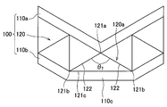
- the laminated metal plate 100 is an example of a conventional laminated metal plate.
- the laminated metal plate 100 includes metal plates 110a and 110b and a truss structure body 120 that is a core layer.
- the metal plates 110 a and 110 b are provided on both sides of the truss structure 120.
- the truss structure 120 is a truss (cone) 120a formed of a metal frame 122 arranged in a matrix.
- the truss 120a can take the shape of a regular quadrangular pyramid, for example.
- the top vertex 121a of the truss 120a is joined to the metal plate 110a, and the vertex on the bottom surface 121c side (hereinafter, the vertex on the bottom surface side of each truss is also referred to as “bottom vertex”) 121b is the metal plate 110b. It is joined to.
- Angle theta 7 shows a joint angle between the trusses 120a and the metal plate 110a.
- the joining angle ⁇ 7 between the truss 120a and the metal plate 110a is obtained by the following procedure.
- a cross section that passes through the junction point between the metal plate 110a and the truss 120a (here, the top vertex 121a of the truss 120a) and is perpendicular to the metal plate 110a is defined.
- the intersection line of this cross section and truss 120a is specified, and the angle prescribed
- a portion of the metal plate 110b to which the bottom surface 121c of a truss 120a is joined (tensile deformation portion) 110c is tensile-deformed, and the metal plate 110a has the truss 120a.
- the portion (compression deformation portion) to which the head vertex 121a is joined undergoes compression deformation (compression deformation in the surface direction of the metal plate 110a)
- the truss 120a cannot sufficiently reinforce the tensile deformation portion 110c. This is because there is no member for reinforcing the tensile deformation portion 110c between the apexes 121b of the truss bottom surface 120c.
- the tensile deformation portion 110c of the metal plate 110b greatly extends. That is, the metal plate 110b is greatly deformed locally. Along with this, the joining angle ⁇ 7 of the truss 120a becomes very large. For this reason, the truss 120a is crushed. That is, the bent portion (corner portion) of the laminated metal plate 100 is crushed. As a result, the strength of the bent portion decreases (strength decrease), and as a result, the bent portion may break (molding failure). In addition, since the thickness of the bent portion is different from the thickness of the other portions and the truss 120a is crushed, the appearance is also poor (exterior appearance). As a result of careful examination of such problems, the present inventor has arrived at the laminated metal plates 11 to 15 according to the first to fifth embodiments.
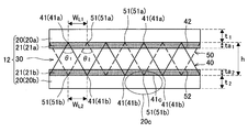
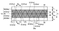
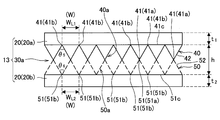
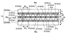
- the vertex 41 of the first truss structure 40 is at least on the first metal plate 20a.
- the top 51 of the second truss structure 50 is joined to at least the second metal plate 20b.
- the first truss structure body 40 is joined to at least one of the second truss structure body 50 and the second metal plate 20b, and the second truss structure body 50 includes the first truss structure body 40 and the second truss structure body 40.
- the vertices 41 and 51 of the first truss structure body 40 and the second truss structure body 50 are the first metal plate 20a and the second metal plate 20b.
- the position of the vertex of the second truss structure 50 is arranged between the vertices of the first truss structure 40.
- the first truss structure body 40 is joined to the first metal plate 20a, and the second truss structure body 50 is joined to the second metal plate 20b. .
- the top vertex 41a of the 1st truss structure body 40 and the top vertex 51a of the 2nd truss structure body 50 are joined within the core layer 30a. Therefore, since the size of the first truss structure body 40 and the second truss structure body 50 is smaller than that of the conventional truss structure body, the unit area of the first metal plate 20a and the second metal plate 20b is smaller than that of the conventional truss structure body. The number of vertices to be joined increases compared to the conventional case.
- each embodiment will be described in detail.
- First Embodiment> (2-1. Overall configuration of laminated metal plate) First, based on FIG. 1, the whole structure of the laminated metal plate 11 which concerns on 1st Embodiment is demonstrated.
- the laminated metal plate 11 includes a core layer 30 and metal plates 20 provided on both surfaces of the core layer 30.
- one metal plate 20 may be distinguished as the first metal plate 20a and the other metal plate 20 as the second metal plate 20b.
- the type (material) of the metal constituting the metal plate 20 is not particularly limited.
- a preferred example of the metal plate 20 is a steel plate, but other types of metal plates may be used. That is, examples of the metal constituting the metal plate include steel, aluminum, titanium, magnesium, copper, nickel, and alloys thereof. Further, the type of the steel plate is not particularly limited. Examples of steel plates that can be used in the present embodiment include tin plates, thin tin-plated steel plates, electrolytic chromic acid-treated steel plates (tin-free steel), nickel-plated steel plates and other can steel plates, hot-dip galvanized steel plates, hot-dip zinc-iron.
- surface-treated steel plates such as a coated steel plate, a printed steel plate, a film laminated steel plate, may be sufficient as a steel plate.
- first metal plate 20a and the second metal plate 20b may be different from each other.
- the core layer 30 is laminated between steel plates with different strengths, mild steel is used for the hard-working surface with a small radius of curvature, and strength is applied to the other surface.
- a known surface treatment can be applied to the surface of the metal plate 20 in order to improve adhesion and corrosion resistance. Examples of such surface treatment include, but are not limited to, chromate treatment (reaction type, coating type, electrolysis) and non-chromic treatment, phosphate treatment, organic resin treatment, and the like.
- the preferred thickness of the metal plate 20 is 0.2 mm to 2.0 mm. If the thickness of the metal plate 20 is less than 0.2 mm, it may be easily buckled during bending. On the other hand, when the thickness of the metal plate 20 exceeds 2.0 mm, the effect of reducing the weight tends to be insufficient. From the viewpoint of weight reduction, the thickness of the metal plate 20 is preferably 1.0 mm or less.
- the thickness of the first metal plate 20a t 1, the thickness t 2 of the second metal plate 20b, unless impair the light effect may not be the same, by increasing the thickness of the one, strong working It becomes easy to avoid buckling and fracture of the surface steel plate at the time.
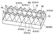
- the core layer 30 includes a first truss structure body 40 and a second truss structure body 50.
- the first truss structure body 40 is a structure in which trusses (cones) 40 a composed of frames 42 are arranged in a matrix.
- the truss 40a has a regular quadrangular pyramid shape.
- the truss 40 a has five vertices 41. In the following description, among these vertices 41, the top vertex may be distinguished as the top vertex 41a, and the bottom vertex 41 may be distinguished as the bottom vertex 41b.
- the material constituting the frame 42 is not particularly limited.
- the frame 42 may be made of the same metal as the metal plate 20 or may be made of resin.
- the resin constituting the frame 42 is not particularly limited, but is preferably, for example, a thermoplastic resin.
- the thermoplastic resin include general-purpose resins, general-purpose engineering plastics, and super engineering plastics.
- the general-purpose resin include polyethylene, polypropylene, polystyrene, and polyvinyl chloride.
- General-purpose engineering plastics include polyamide, polyacetal, polycarbonate, modified polyphenylene ether, polyester, and the like.
- super engineering plastics include amorphous polyarylate, polysulfone, polyether sulfone, polyphenylene sulfide, polyether ether ketone, polyimide, polyether imide, and fluororesin.
- the frame 42 is preferably made of metal.
- the frame 42 may be made of either metal or resin.
- the frame 42 By configuring the frame 42 with resin, it is possible to expect an effect that the heat insulating property and insulating property of the laminated metal plate 11 are improved and the weight of the laminated metal plate 11 is reduced.
- the frame 42 by configuring the frame 42 with a super engineering plastic, the heat resistance of the laminated metal plate 11 (for example, heat resistance against a temperature of 150 ° C. or higher) is particularly improved.
- the strength of the frame 42 can be increased by configuring the frame 42 with a fiber reinforced resin (including the fiber material such as carbon fiber and glass fiber in the resin).
- a resin truss structure may be laminated on the surface of the laminated metal plate 11. In this case, the surface lubricity and heat insulation of the laminated metal plate 11 can be further improved.
- the top vertex 41a of the truss 40a is joined to the first metal plate 20a, and the bottom vertex 41b is joined to the second metal plate 20b.
- the joining angle ⁇ 11 between the truss 40a and the first metal plate 20a is preferably 60 to 150 °. This is because when the joining angle ⁇ 11 is 60 to 150 °, the laminated metal plate 11 is resistant to shear deformation and compression deformation in the plate thickness direction.
- the shear deformation in this embodiment means shear deformation that occurs when a force is applied in a direction parallel to the laminated metal plate 11, and the compressive deformation in the plate thickness direction is a force perpendicular to the laminated metal plate 11. It means the compression deformation that occurs when.
- the frame 42 of the truss 40a is joined to the surfaces of the first metal plate 20a and the second metal plate 20b at an inclination, the strength against shear deformation is increased.
- the bonding angle theta 11 becomes less than 60 °, since the number of trusses 40a occupying the core layer 30 is increased, the mass of the metal plate stack 11 is increased. Therefore, it is not preferable from the viewpoint of weight reduction. Moreover, the tolerance with respect to the shear deformation of the laminated metal plate 11 may fall. On the other hand, if the bonding angle theta 11 exceeds 0.99 °, it is possible that the metal plate stack 11 is weakened to the compression deformation in the thickness direction.
- the joining angle ⁇ 11 may be set to 60 to 90 °. In addition, when it is desired to make the laminated metal plate 11 particularly resistant to shear deformation, the joining angle ⁇ 11 may be set to more than 90 ° to 150 °. In this case, the laminated metal plate 11 can be further reduced in weight. In the case of the bonding angle theta 11 about 0.99 °, since the metal plate stack 11 is likely to slightly weaken the compression deformation in the thickness direction, as described in the second embodiment described below, the resin It is preferable to form the layer 21 on the surface of the first metal plate 20a. In this case, the joining point is reinforced by the resin layer 21, and as a result, the laminated metal plate 11 becomes resistant to compressive deformation in the plate thickness direction.
- the junction angle theta 11 is determined by the following procedure. That is, a cross section that passes through the junction point between the first metal plate 20a and the truss 40a (here, the top vertex 41a of the truss 40a) and is perpendicular to the first metal plate 20a is defined. And the intersection line of this cross section and truss 40a is specified, and the angle prescribed
- the magnitude of the joining angle ⁇ 11 may vary depending on how the cross section is defined. However, even if the cross section is defined, the joining angle ⁇ 11 satisfies the conditions shown in this embodiment. It is preferable to satisfy.
- the joining angle ⁇ 12 between the truss 40a and the second metal plate 20b is preferably 60 to 150 °.
- the reason is the same reason as described with respect to joining angle theta 11.
- the bonding angle theta 12 may be set to 60 ⁇ 90 °.
- the joint angle theta 12 may be set to 90 ° ultra ⁇ 0.99 °. In this case, the laminated metal plate 11 can be further reduced in weight.
- the bonding angle theta 12 about 0.99 °, as described in the second embodiment described later, it is preferable to form the resin layer 21 on the surface of the second metal plate 20b. In this case, the joint point is reinforced by the resin layer 21.
- the junction angle theta 12 is determined by the following procedure. That is, a cross section that passes through the junction of the second metal plate 20b and the truss 40a (here, the bottom vertex 41b of the truss 40a) and is perpendicular to the second metal plate 20b is defined. And the intersection line of this cross section and truss 40a is specified, and the angle prescribed
- the condition is the size of the joint angle theta 12 depending on how to define the cross section may vary, even when the defined how the cross section, bonding the angle theta 12 is shown in this embodiment It is preferable to satisfy.
- the angle theta 13 and the bottom surface 41c of the frame 42 and truss 40a of the truss 40a is about 30 ⁇ 60 °, and more preferably about 45 ⁇ 60 °.
- the height of the truss 40a, that is, the height (thickness) of the first truss structure 40 is not particularly limited, but is preferably 1 mm or more and 5 mm or less in consideration of the workability of the laminated metal plate 11 and the like.
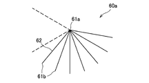
- the truss constituting the first truss structure 40 may be an n-pyramidal truss 60a shown in FIG.
- the n-pyramidal truss 60 includes a top vertex 61a, a bottom vertex 61b, and a frame 62.
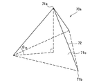
- the n-pyramidal truss is a triangular pyramid truss 70a shown in FIG.
- the triangular pyramid truss 70a includes a head vertex 71a, a bottom vertex 71b, and a frame 72.
- the angle ⁇ 14 formed between the frame 72 and the bottom surface 71c of the triangular pyramid-shaped truss 70a is preferably about 30 to 60 °, and more preferably about 45 to 60 °. The same applies to the n-pyramidal truss 60.
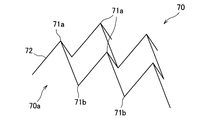
- FIG. 7 shows a truss structure 70 in which triangular pyramid trusses 70a are arranged in a matrix. The most preferable shape of the truss 40a is a regular pyramid shown in FIG.
- the second truss structure body 50 is a structure in which trusses (cones) 50a composed of frames 52 are arranged in a matrix.
- the second truss structure 50 has a configuration similar to that of the first truss structure 40. That is, the truss 50a has a regular quadrangular pyramid shape as shown in FIGS.
- the truss 50 a has five vertices 51. In the following description, among these vertices 51, the top vertex may be distinguished as the top vertex 51a, and the bottom vertex 51 may be distinguished as the bottom vertex 51b.
- the material constituting the frame 52 is not particularly limited.
- the frame 52 may be made of the same material as the frame 42.
- the effect of each material is the same as the effect described in the frame 42.
- the top vertex 51a of the truss 50a is joined to the first metal plate 20a, and the bottom vertex 51b is joined to the second metal plate 20b. Further, the head vertex 51 a is disposed between the head vertices 41 a of the first truss structure body 40. The head vertices 51 a are preferably arranged at the center between the head vertices 41 a of the first truss structure 40. Further, the bottom vertex 51 b is disposed between the bottom vertices 41 b of the first truss structure body 40. The bottom vertices 51b are preferably arranged at the center between the bottom vertices 41b of the first truss structure 40.
- the top vertex 41a of the first truss structure body 40 and the top vertex 51a of the second truss structure 50 are joined to the first metal plate 20a, and the first truss structure body.
- the bottom vertex 41b of 40 and the bottom vertex 51b of the second truss structure 50 are joined to the second metal plate 20b.
- a plane (virtual plane) passing through the junction point between the first truss structure body 40 and the second truss structure body 50 and the first metal plate 20 a forms one surface of the core layer 30.
- a plane (virtual plane) passing through the junction point between the first truss structure body 40 and the second truss structure 50 and the second metal plate 20 b forms the other surface of the core layer 30.
- the thickness of the core layer 30 is defined as the distance between the surfaces of the core layer 30.
- the thickness of the core layer 30 substantially corresponds to the height of the first truss structure 40 (or the second truss structure 50). Also in each embodiment described later, the surface and thickness of the core layer are similarly defined.
- the joining angle ⁇ 21 between the truss 50a and the first metal plate 20a is preferably 60 to 150 °.
- the reason is the same reason as described with respect to joining angle theta 11.
- the joining angle ⁇ 21 may be set to 60 to 90 °.
- the joining angle ⁇ 21 may be set to more than 90 ° to 150 °. In this case, the laminated metal plate 11 can be further reduced in weight.
- the bonding angle theta 21, about 0.99 °, as described in the second embodiment described later it is preferable to form the resin layer 21 on the surface of the first metal plate 20a. In this case, the joint point is reinforced by the resin layer 21.
- the method for obtaining the joining angle ⁇ 21 is the same as the method for obtaining the joining angle ⁇ 11 . That is, a cross section that passes through the junction between the first metal plate 20a and the truss 50a (here, the top vertex 51a of the truss 50a) and is perpendicular to the first metal plate 20a is defined. And the intersection line of this cross section and truss 50a is specified, and the angle prescribed
- the magnitude of the joining angle ⁇ 21 may vary depending on how the cross section is defined, the joining angle ⁇ 21 satisfies the conditions shown in the present embodiment even when the cross section is defined. It is preferable to satisfy.
- FIG. 4 shows an example of the bonding angle ⁇ 21 .
- the joining angle ⁇ 22 between the truss 50a and the second metal plate 20b is preferably 60 to 150 °.
- the reason is the same reason as described with respect to joining angle theta 11.
- the joining angle ⁇ 22 may be set to 60 to 90 °.
- the joining angle ⁇ 22 may be set to more than 90 ° to 150 °. In this case, the laminated metal plate 11 can be further reduced in weight.
- the bonding angle theta 22 about 0.99 °, as described in the second embodiment described later, it is preferable to form the resin layer 21 on the surface of the second metal plate 20b. In this case, the joint point is reinforced by the resin layer 21.
- the joining angle ⁇ 22 is obtained by the following procedure. That is, a cross section that passes through the junction point between the second metal plate 20b and the truss 50a (here, the bottom vertex 51b of the truss 50a) and is perpendicular to the second metal plate 20b is defined. And the intersection line of this cross section and truss 50a is specified, and the angle prescribed
- the magnitude of the joining angle ⁇ 22 may vary depending on how the cross section is defined, the joining angle ⁇ 22 satisfies the conditions shown in the present embodiment even when the cross section is defined. It is preferable to satisfy.
- the angle ⁇ 23 formed by the frame 52 of the truss 50a and the bottom surface of the truss 50a is preferably about 30 to 60 °, and more preferably about 45 to 60 °.
- the height of the truss 50a, that is, the height (thickness) of the second truss structure 50 is not particularly limited, but is preferably 1 mm or more and 5 mm or less in consideration of the workability of the laminated metal plate 11 and the like.
- the truss 50a may be a truss shown in FIGS.
- the vertex 51 of the second truss structure body 50 is disposed between the vertices 41 of the first truss structure body 40, so the first metal plate 20a and the number of vertices in contact per unit area of the second metal plate 20b are increased as compared with the conventional case. Thereby, the strength, formability, and appearance of the bent portion are improved.
- a portion (tensile deformation portion) 20c of the second metal plate 20b with which the bottom surface of the truss 40a contacts is tensile-deformed.
- the tensile deformation part 20c is The bottom vertices 51b disposed between the bottom vertices 41b of the bottom surface 41c are reinforced. In other words, since the tensile deformation portion is divided by the bottom vertex 51b, local tensile deformation is suppressed.
- the angle change in the joint angle theta 11 is suppressed. That is, the collapse of the truss 40a is suppressed. Therefore, collapse of the bent portion (corner portion) of the laminated metal plate 11 is also suppressed. As a result, the strength of the bent portion is improved, and breakage of the bent portion is suppressed. In addition, since the difference between the thickness of the bent portion and the thickness of the other portion is reduced, the appearance is improved. Therefore, the strength, formability, and appearance of the bent portion are improved.
- the distance between the second metal plate 20b and the second metal plate 20b is preferably 0.4 times or more and 4.0 times or less, and more preferably 1.0 times or more and 1.8 times or less.
- the bottom vertex 41b joined to the second metal plate 20b, the distance W L2 between 51b is preferably has a total thickness is 0.4 times to 4.0 times or less of the metal plate stack 11, 1 It is more preferable that the ratio is not less than 0.0 times and not more than 1.8 times.
- At least one of the vertex distances W L1 and W L2 satisfies the condition of the following mathematical formula (1). 0.57 ⁇ w / h ⁇ 3.7 / ⁇ (1)
- w represents the distance between the vertices W L1 and W L2
- h represents the distance between the first metal plate 20a and the second metal plate 20b
- ⁇ represents the bonding at the time of bending.
- the change rate of an angle (joining angle on the compression deformation side) is shown.
- the change rate ⁇ is calculated by the following procedure.
- the change amount of w when the laminated metal plate 11 is bent with a certain radius of curvature is calculated by geometric calculation, and the change amount of the joining angle is calculated based on the result. Then, the change rate ⁇ is calculated based on the change amount of the joining angle.
- w / h represents tan ( ⁇ / 2) ( ⁇ : joining angle on the compression deformation side among ⁇ 11 to ⁇ 14 ).
- the lower limit value 0.57 is a value of tan (60/2). That is, when w / h is less than 0.57, the number of trusses 40a in the core layer 30 increases, so that the mass of the laminated metal plate 11 increases. Therefore, it is not preferable from the viewpoint of weight reduction. Moreover, the tolerance with respect to the shear deformation of the laminated metal plate 11 may fall.
- the upper limit value 3.7 is a value of tan (150/2). That is, according to the above formula (2), it is not preferable that the joint angle after bending exceeds 150 °. This is because if the joining angle exceeds 150 °, the resistance to compression deformation in the thickness direction may be reduced.
- the inter-vertex distance W L1 is preferably 30 times or less the thickness t 1 of the first metal plate 20a. It is more preferably less than twice.
- the vertex distance WL2 is preferably 30 times or less of the thickness t2 of the second metal plate 20b, and more preferably 10 times or less.
- the core layer 30 and the metal plate 20 are joined with an adhesive.
- the adhesive is not particularly limited, and can be used without any problem in this embodiment as long as it is an adhesive used for a laminated metal plate using a truss structure as a core layer.
- a structural adhesive based on an epoxy resin is preferable.
- a one-component heat curable adhesive premixed with a curing agent is preferable for handling.
- a conductive adhesive is preferable.
- the conductive adhesive include those obtained by adding a predetermined amount of metal powder such as aluminum powder, nickel powder, and iron powder to the adhesive as described above.
- the core layer 30 and the metal plate 20 may be joined by blaze joining, seam welding, or the like.
- the wire mesh 200 is a sheet-like member in which the frame 201 is distributed in a mesh shape, and has a large number of openings 202.
- the opening 202 is a square, but the shape of the opening 202 is not limited to a square.
- the type of wire mesh 200 is not particularly limited.
- the wire mesh 200 may be a wire mesh produced by weaving metal wires into a mesh shape (hereinafter, such a wire mesh is also referred to as “knitted wire mesh”).
- the metal wire becomes the frame 201.
- the intersection of the frames 201 constitutes the vertices of the first truss structure body 40 and the second truss structure body 50, so the strength of the vertices decreases.
- the shape of the truss structure can be prevented while preventing the metal wire from being broken by using a bonding material having a deformability capable of withstanding the displacement deformation during bending. This is preferable because it can be maintained.
- the angle when the metal mesh 200 is folded and valley folded is an acute angle, there is still a high possibility that the frame 201 and the welded portion are broken.
- the wire mesh 200 may be a wire mesh (so-called punching metal) produced by forming a large number of punching holes in a metal plate.
- the metal portion (so-called “bar”) between the punching holes becomes the frame 201.
- the metal mesh 200 is formed by forming a large number of notches in a metal plate and then extending the metal plate in a direction intersecting with the length direction of the notches (that is, expanding the notches) ( So-called expanded metal) may be used. In this case, the metal portion between the expanded notches becomes the frame 201.
- the metal net 200 is a punching metal or an expanded metal
- the first truss structure body 40 and the second truss structure body 50 are manufactured by molding a metal plate.
- the wire mesh 200 is preferably composed of a punching metal or an expanded metal among the braided wire mesh, the punching metal, and the expanded metal. Moreover, it is more preferable that the metal mesh 200 is made of punching metal.
- the reason for this is as follows. That is, when the wire mesh 200 is formed of a braided wire mesh, it is necessary to weave the wire mesh, so that the manufacturing cost (raw material cost) of the wire mesh 200 increases. Furthermore, since the intersection of the frames 201 constitutes the apexes of the first truss structure body 40 and the second truss structure body 50, the strength of the apex decreases. This is because there is a possibility that the frames 201 constituting the vertices are shifted from each other.
- the frame 201 and the welded portion may be broken when the metal mesh 200 is alternately folded and folded.
- the angle of the mountain fold or the valley fold is an acute angle, there is a high possibility that the frame 201 or the welded portion is broken.
- the punching metal and the expanded metal are produced by simply forming a metal plate, the manufacturing cost is lower than that of the braided wire mesh. In addition, the strength of the vertex is ensured.
- the wire mesh 200 is made of a punching metal
- punching metal having various shapes can be produced simply by changing the structure (shape, thickness, size, etc.) of the hole when punching the metal plate.
- various shapes of the first truss structure body 40 and the second truss structure body 50 can be manufactured at low cost.
- the metal mesh 200 is made of punching metal
- the intersection of the frames 201 becomes flat, so that the strength of the apex is improved.
- expanded metal is formed by extending a metal plate after forming a notch in the metal plate. Accordingly, irregularities are formed at the intersections between the frames 201.
- this intersection part forms the vertex of the 1st truss structure body 40 and the 2nd truss structure body 50, the intensity
- a method of pressing expanded metal is conceivable.
- this method increases the manufacturing cost because the number of steps called pressing increases.
- processing distortion arises in the uneven
- the concavo-convex portions that is, the portions forming the vertices 41 and 51 of the first truss structure body 40 and the second truss structure body 50 are broken (for example, cracks are formed at or near the vertices 41 and 51.
- the laminated metal plate 11 is produced using the cracked truss structure, the following problems may arise. That is, when a shearing force is applied to the laminated metal plate 11, the stress concentrates on the crack portion, and the frame of the truss structure body may be completely cut from the crack portion.
- the first truss structure body 40 and the second truss structure body 50 are manufactured using expanded metal, as shown in the second embodiment, the first truss structure body 40 and the second truss structure body 40
- the junction point between the truss structure body 50 and the first metal plate 20a and the second metal plate 20b may be protected by the resin layer 21.
- the first truss structure body 40 and the second truss structure body 50 are manufactured by alternately folding the metal mesh 200 in a straight line A and B (straight line connecting the diagonal lines of the opening 202) and in a valley. According to this method, it is possible to manufacture the first truss structure body 40 and the second truss structure body 50 in which the trusses 40a and 50a have a triangular pyramid shape, a regular quadrangular pyramid shape, and a quadrangular pyramid shape.
- first truss structure 40 and the second truss structure 50 are resin frames, a mold for the first truss structure 40 and the second truss structure 50 is prepared, and the first truss structure 40 and the second truss structure 50 are prepared using the molds.
- the two truss structures 50 may be produced.
- the first truss structure 40 and the second truss structure 50 are overlapped so that the vertex 51 of the second truss structure 50 is disposed between the vertices 41 of the first truss structure 40. Thereby, the core layer 30 is produced.
- an adhesive is applied to both surfaces of the core layer 30, and the metal plate 20 is bonded to both surfaces of the core layer 30. Bonding is performed by pressing the metal plate 20 toward the core layer 30 at room temperature or under heating. Thereby, the laminated metal plate 11 is produced.
- the vertex 51 of the second truss structure 50 is arranged between the vertices 41 of the first truss structure 40, for example, the bottom surface 41c of the truss 40a is joined.
- the portion to be deformed tensile deformation portion
- the tensile deformation portion is reinforced by the vertex 51 of the second truss structure body 50. Therefore, the truss 40a is prevented from being crushed, and as a result, the strength, formability, and appearance of the bent portion are improved.
- the laminated metal plate of the present invention can improve the rigidity, impact resistance (collision safety), and workability as compared with the conventional laminated metal plate while satisfying the needs for weight reduction. Therefore, the laminated metal plate of the present invention can be used for structural members that require collision safety, in addition to panels that form flat and curved surfaces such as transporters.
- 2nd Embodiment is described.
- the laminated metal plate 12 according to the second embodiment is obtained by adding a resin layer 21 to the laminated metal plate 11 according to the first embodiment.
- the resin layer 21 is provided on each of the surface of the first metal plate 20a (the surface on the core layer 30 side) and the surface of the second metal plate 20b (the surface on the core layer 30 side). Yes.
- the resin layer 21 on the first metal plate 20a may be distinguished as the first resin layer 21a
- the resin layer 21 on the second metal plate 20b may be distinguished as the second resin layer 21b.
- Either the first resin layer 21a or the second resin layer 21b may be omitted.
- the apexes of the first truss structure body 40 and the second truss structure body 50 are recessed into the resin layer 21, and are joined to the first metal plate 20a and the second metal plate 20b.
- the joint points of the first truss structure body 40 and the second truss structure body 50 with the first metal plate 20a and the second metal plate 20b are protected by the resin layer 21. Has been.
- the type of the resin constituting the resin layer 21 is not particularly limited, but is preferably a thermoplastic resin from the viewpoint of processing.
- the thermoplastic resin include general-purpose resins, general-purpose engineering plastics, and super engineering plastics.
- the general-purpose resin include polyethylene, polypropylene, polystyrene, and polyvinyl chloride.
- General-purpose engineering plastics include polyamide, polyacetal, polycarbonate, modified polyphenylene ether, polyester, and the like.
- Examples of super engineering plastics include amorphous polyarylate, polysulfone, polyether sulfone, polyphenylene sulfide, polyether ether ketone, polyimide, polyether imide, and fluororesin.
- the joint point can be reinforced by forming the resin layer 21 with the above-described thermoplastic resin. Specifically, the peel strength between the first truss structure body 40 and the second truss structure body 50 and the first metal plate 20a and the second metal plate 20b can be improved.
- the resin layer 21 also functions as an adhesive that joins the first truss structure body 40 and the second truss structure body 50 to the first metal plate 20a and the second metal plate 20b. Therefore, in the second embodiment, the adhesive used in the first embodiment can be made unnecessary.
- first metal plate 20a and the second metal plate 20b and the first truss structure body 40 and the first metal plate 20a and the second metal plate 20b are formed only by forming the resin layer 21 on the surfaces of the first metal plate 20a and the second metal plate 20b.
- the second truss structure 50 can be joined. Therefore, the productivity of the laminated metal plate 12 is improved.
- the resin layer 21 is constituted by a general engineering plastic or a super engineering plastic, a further reinforcing effect can be obtained. Specifically, deformation of the vertices of the first truss structure body 40 and the second truss structure body 50 can be suppressed. Therefore, when the laminated metal plate 11 is bent, the strength of the bent portion can be further improved. Furthermore, when the resin layer 21 is composed of a super engineering plastic, the heat resistance (for example, heat resistance with respect to a temperature of 150 ° C. or higher) of the laminated metal plate 12 is improved.
- the resin constituting the resin layer 21 may be a foam or a bulk body.
- the strength of the laminated metal plate 12 against compressive deformation in the thickness direction can be further improved. It can.
- a laminated metal plate in which the space between the first metal plate 20a and the second metal plate 20b is filled only with resin also has a high strength against compression deformation.
- this laminated metal plate has a very low strength against shear deformation. This is because the interfaces between the first metal plate 20a and the second metal plate 20b and the resin layer are flat.
- many joint points described above are formed at the interface between the first metal plate 20a and the second metal plate 20b and the resin layer.
- the frames 42 and 52 of the first truss structure body 40 and the second truss structure body 50 are joined to the surfaces of the first metal plate 20a and the second metal plate 20b in an inclined manner. Therefore, the laminated metal plate 12 has a high strength against shear deformation. Furthermore, the first metal plate 20 a and the second metal plate 20 b are held not only by the first truss structure body 40 and the second truss structure body 50 but also by the resin layer 21. For this reason, when the laminated metal plate 11 is cut, the first metal plate 20a and the second metal plate 20b hardly change in the thickness direction of the laminated metal plate 11 (it is difficult to sink in the thickness direction).
- the laminated metal plate 12 can be manufactured by the following steps. First, the core layer 30 is produced by the same process as in the first embodiment. Next, a first resin layer 21a is formed on the surface of the first metal plate 20a by laminating a resin sheet on the surface of the first metal plate 20a. The second resin layer 21b is formed on the surface of the second metal plate 20b by the same process. Next, the first resin layer 21a and the second resin layer 21b are softened by heating the first resin layer 21a and the second resin layer 21b. Next, the core layer 30 is bonded to the first metal plate 20a and the second metal plate 20b.
- the first truss structure body 40 and the second truss structure body 50 push the first resin layer 21a and the second resin layer 21b to the first metal plate 20a and the second metal plate 20b. Contact. Thereafter, the first resin layer 21a and the second resin layer 21b are cured, for example, by cooling the first resin layer 21a and the second resin layer 21b. Thereby, the 1st truss structure body 40 and the 2nd truss structure body 50 are joined to the 1st metal plate 20a and the 2nd metal plate 20b. That is, the first resin layer 21a and the second resin layer 21b function as an adhesive. However, from the viewpoint of further securing the bonding strength, a bonding method similar to that of the first embodiment may be further performed.
- the core layer 30a is a laminate of the first truss structure body 40 and the second truss structure body 50.
- the top vertex 41a of the first truss structure 40 is joined to the top vertex 51a of the second truss structure 50, and the bottom vertex 41b of the first truss structure 40 is joined to the first metal plate 20a. ing.
- the bottom vertex 51b of the second truss structure 50 is joined to the second metal plate 20b.
- the first truss structure body 40 and the second truss structure body 50 are joined together by the above-described adhesive (or blaze joining, seam welding, or the like).
- the first truss structure body 40 and the second truss structure body 50 have the same shape, but may have different shapes.
- the sizes of the first truss structure body 40 and the second truss structure body 50 (specifically, the first truss structure)
- the size of the trusses 40a and 50a constituting the structure 40 and the second truss structure 50) is smaller than that of the conventional truss structure (in the example of FIG. 11, it is half that of the conventional one). Therefore, since the number of vertices 41 and 51 to be bonded per unit area of the first metal plate 20a and the second metal plate 20b is larger than before, the strength of the bent portion of the laminated metal plate 11, the formability, And the appearance is improved.
- the joining angle ⁇ 5 between the truss 40a and the first metal plate 20a is preferably 60 to 150 °.
- the reason is the same reason as described with respect to joining angle theta 11.
- the joining angle ⁇ 5 may be set to 60 to 90 °.
- the joining angle ⁇ 5 may be set to more than 90 ° to 150 °. In this case, the laminated metal plate 13 can be further reduced in weight.
- the bonding angle theta 5 and about 0.99 ° it is preferable to form the resin layer 21 on the surface of the first metal plate 20a. In this case, the joint point is reinforced by the resin layer 21.
- the bonding angle ⁇ 5 is obtained by the following procedure. That is, a cross section that passes through the junction point between the first metal plate 20a and the truss 40a (here, the bottom vertex 41b of the truss 40a) and is perpendicular to the first metal plate 20a is defined. And the intersection line of this cross section and truss 40a is specified, and the angle prescribed
- the magnitude of the joining angle ⁇ 5 may vary depending on how the cross section is defined, but the joining angle ⁇ 5 satisfies the conditions shown in this embodiment even when the cross section is defined. It is preferable to satisfy.
- the joining angle ⁇ 6 between the truss 50a and the second metal plate 20b is preferably 60 to 150 °.
- the reason is the same reason as described with respect to joining angle theta 11.
- the joining angle ⁇ 6 may be set to 60 to 90 °.
- the joining angle ⁇ 6 may be set to more than 90 ° to 150 °. In this case, the laminated metal plate 13 can be further reduced in weight.
- the joining angle ⁇ 6 is about 150 °, it is preferable to form the resin layer 21 on the surface of the second metal plate 20b as described in a fourth embodiment described later. In this case, the joint point is reinforced by the resin layer 21.
- the joining angle ⁇ 6 is obtained by the following procedure. That is, a cross section that passes through the junction point between the second metal plate 20b and the truss 50a (here, the bottom vertex 51b of the truss 50a) and is perpendicular to the second metal plate 20b is defined. And the intersection line of this cross section and the truss 50a is specified, and the angle prescribed
- the magnitude of the joining angle ⁇ 6 may vary depending on how the cross section is defined, the joining angle ⁇ 6 satisfies the conditions shown in this embodiment even when the cross section is defined. It is preferable to satisfy.
- the distance W L1 between the bottom vertices 41b joined to the first metal plate 20a is preferably not less than 0.4 times and not more than 4.0 times the total thickness of the laminated metal plate 11, It is more preferable that it is not less than twice and not more than 1.8 times.
- the distance W L2 between the bottom apex 51b joined to the second metal plate 20b is preferably has a total thickness is 0.4 times or more and 4.0 or less of the metal plate stack 11, 1.0 More preferably, it is 1.8 times or less.
- the vertex distance WL1 is preferably 30 times or less of the thickness t1 of the first metal plate 20a, and 10 times. The following is more preferable.
- the vertex distance WL2 is preferably 30 times or less of the thickness t2 of the second metal plate 20b, and more preferably 10 times or less.
- the laminated metal plate 13 can be manufactured by the following steps. First, the 1st truss structure body 40 and the 2nd truss structure body 50 are produced by the process similar to 1st Embodiment. And the core layer 30a is produced by joining the top vertex 41a of the 1st truss structure body 40, and the top vertex 51a of the 2nd truss structure body 50. FIG. The joining method may be the same as the joining method of the first metal plate 20 a and the second metal plate 20 b and the core layer 30. After that, the same process as that of the first embodiment is performed to manufacture the laminated metal plate 13.
- the laminated metal plate 14 according to the fourth embodiment is obtained by adding a resin layer 21 to the laminated metal plate 13 according to the third embodiment.
- the surface of the first metal plate 20a (the surface on the core layer 30 side), the surface of the second metal plate 20b (the surface on the core layer 30 side), the first truss structure body 40, and the first A resin layer 21 is provided on each of the joining portions of the two truss structures 50.
- the resin layer 21 on the first metal plate 20a is the first resin layer 21a
- the resin layer 21 on the second metal plate 20b is the second resin layer 21b
- the first truss structure The resin layer 21 at the joint between the body 40 and the second truss structure 50 may be distinguished as the third resin layer 21c. Any one of the first resin layer 21a, the second resin layer 21b, and the third resin layer 21c may be omitted.
- the bottom vertices 41b and 51b of the first truss structure body 40 and the second truss structure body 50 are recessed into the first resin layer 21a and the second resin layer 21b, and the first metal plate 20a. , And the second metal plate 20b. Furthermore, the top vertices 41a and 51a of the first truss structure body 40 and the second truss structure body 50 are recessed into the third resin layer 21c and are joined to each other.
- the joint points of the first truss structure body 40 and the second truss structure body 50 with the first metal plate 20a and the second metal plate 20b are the first resin layer. It is protected by 21a and the second resin layer 21b. Furthermore, the joint point between the first truss structure body 40 and the second truss structure body 50 is also protected by the third resin layer 21c.
- the resin constituting the resin layer 21 is not particularly limited, and may be made of the same resin as in the second embodiment. In this case, the same effect as in the second embodiment can be obtained. Furthermore, an adhesive for joining the first truss structure body 40 and the second truss structure body 50 becomes unnecessary. Furthermore, the peel strength between the first truss structure body 40 and the second truss structure body 50 can be improved. Further, the first truss structure body 40 and the second truss structure body 50 can be joined only by forming the third resin layer 21 c on the top vertex 41 a of the first truss structure body 40. Therefore, the productivity of the laminated metal plate 14 is improved.
- the thickness of the first resin layer 21a ta 1, the thickness ta 3 thickness ta 2, and the third resin layer 21c of the second resin layer 21b is not particularly limited. However, the total sum of these thicknesses ta 1 , ta 2 , and ta 3 (total thickness of the resin layer 21) may be substantially matched to the distance between the first metal plate 20 a and the second metal plate 20 b. . By making the total thickness of the resin layer 21 substantially coincide with the distance between the first metal plate 20a and the second metal plate 20b, the strength of the laminated metal plate 12 against compressive deformation in the thickness direction can be further improved. it can.
- first metal plate 20 a and the second metal plate 20 b are held not only by the first truss structure body 40 and the second truss structure body 50 but also by the resin layer 21. For this reason, when the laminated metal plate 15 is cut, the first metal plate 20a and the second metal plate 20b hardly change in the thickness direction of the laminated metal plate 15 (it is difficult to sink in the thickness direction).
- the laminated metal plate 14 can be manufactured by the following steps. First, the 1st truss structure body 40 and the 2nd truss structure body 50 are produced by the process similar to 1st Embodiment. And the core layer 30a is produced by joining the top vertex 41a of the 1st truss structure body 40, and the top vertex 51a of the 2nd truss structure body 50. FIG. Specifically, a resin sheet is laminated on the top vertex 41 a of the first truss structure body 40. Next, the resin sheet is softened by heating or the like.
- the resin sheet is cured by cooling the resin sheet or the like. Thereby, the 1st truss structure body 40 and the 2nd truss structure body 50 are joined mutually.
- the resin sheet is the third resin layer 21c.
- a bonding method similar to that of the first embodiment may be further performed. After that, the same process as that of the third embodiment is performed to manufacture the laminated metal plate 14.
- the core layer 30 is configured only by the first truss structure body 40, and a resin layer is provided between the first metal plate 20a and the second metal plate 20b. 21. That is, in the fifth embodiment, the first metal plate 20a is joined to the head vertex 41a (first vertex) of the first truss structure body 40, and the second metal plate 20b is joined to the first truss. It is joined to the bottom vertex 41b (second vertex) of the structure 40. In addition, the resin layer 21 is provided on the surface of the first metal plate 20a and the second metal plate 20b on the core layer 30 side.
- board thickness direction becomes large rather than the laminated metal plate which filled only the resin between the 1st metal plate 20a and the 2nd metal plate 20b.
- the strength against shear deformation and compression deformation in the plate thickness direction is smaller than that of the laminated metal plate 12 shown in FIG.
- first metal plate 20 a and the second metal plate 20 b are held not only by the first truss structure body 40 but also by the resin layer 21. For this reason, when the laminated metal plate 15 is cut, the first metal plate 20a and the second metal plate 20b hardly change in the thickness direction of the laminated metal plate 15 (it is difficult to sink in the thickness direction).
- the laminated metal plate 15 can be manufactured by the following steps. First, the 1st truss structure body 40 is produced according to the process similar to 1st Embodiment. Next, a resin sheet is laminated on the surface of the first metal plate 20a, thereby forming a resin layer 21 (first resin layer 21a) on the surface of the first metal plate 20a. The resin layer 21 (second resin layer 21b) is formed on the surface of the second metal plate 20b by the same process.
- the resin layer 21 is formed only on the surface of the first metal plate 20a (or the second metal plate 20b), and the thickness of the resin layer 21 is set to the first metal plate 20a and the second metal plate 20b.
- the first resin layer 21a and the second resin layer 21b are softened by heating the first resin layer 21a and the second resin layer 21b.
- the core layer 30 is bonded to the first metal plate 20a and the second metal plate 20b.
- the first truss structure body 40 pushes the first resin layer 21a and the second resin layer 21b and contacts the first metal plate 20a and the second metal plate 20b.
- the 1st resin layer 21a and the 2nd resin layer 21b are integrated, and the resin layer 21 which consists of a single layer is formed. Thereafter, the resin layer 21 is cured, for example, by cooling the resin layer 21.
- the 1st truss structure body 40 is joined to the 1st metal plate 20a and the 2nd metal plate 20b. That is, the first resin layer 21a and the second resin layer 21b function as an adhesive. However, from the viewpoint of further securing the bonding strength, a bonding method similar to that of the first embodiment may be further performed.
- the laminated metal plate 15 is produced through the above steps.
- Example 1 (Production of laminated metal plates)
- the 1st truss structure body 40 and the 2nd truss structure body 50 were produced with the following manufacturing methods. That is, an expanded metal having a large number of square openings (material SPCC (JIS G3141), frame thickness: 0.8 mm) is prepared, and this expanded metal is press-molded with a die provided with a V-shaped groove. Thus, one row of regular quadrangular pyramid trusses 40a was produced. And the 1st truss structure 40 by which the truss 40a was arrange
- the first truss structure body 40 and the second truss structure body 50 were overlapped so that the vertex 51 of the second truss structure body 50 was disposed between the vertices 41 of the first truss structure body 40.
- the top vertex 51a of the second truss structure 50 is disposed at the center between the head vertices 41a of the first truss structure 40
- the bottom vertex 51b of the second truss structure 50 is the first vertex 51b.
- the first truss structure 40 and the second truss structure 50 were overlapped so as to be arranged at the center between the bottom vertices 41 b of the truss structure 40. Thereby, the core layer 30 was produced.
- a plurality of types of cold-rolled steel plates (metal plates 20) having different thicknesses are prepared, and using these metal plates 20, the vertex-to-vertex distances W L1 and W L2 are 0.35 of the total thickness of the laminated metal plates 11, A plurality of types of laminated metal plates 11 (Examples) of 0.40, 1.0, 1.4, 1.8, 4.0, and 4.5 times were manufactured.
- the metal plate 20 and the core layer 30 were joined by an adhesive (epoxy system).
- the bending test was performed by the following method. Specifically, the distance between the fulcrums was set to 100 mm, and the punch 5R was pushed to 50 mm. And the angle of the top vertex of the truss of a bending part, ie, the change of joining angle (theta) 11 , was measured visually. As a result, the change in the bonding angle ⁇ 11 when the inter-vertex distances W L1 and W L2 are 0.40, 1.0, 1.4, 1.8, and 4.0 times the total thickness of the laminated metal plate 11. Was smaller than the change in the joining angle ⁇ 11 when the inter-vertex distances W L1 and W L2 were 0.35 and 4.5 times the total thickness of the laminated metal plate 11.
- the change in the joining angle ⁇ 11 is the inter-vertex distances W L1 and W L L2 is smaller than the variation of the bonding angle theta 11 when the 0.40,4.0 times the total thickness of the metal plate stack 11.
- each laminated metal plate 10 was visually observed, but almost no indentation of the metal plate 20 into the core layer 30 was observed.
- the inter-vertex distances W L1 and W L2 are not less than 0.4 times and not more than 4.0 times the total thickness of the laminated metal plate 11, the strength, formability, and appearance of the bent portion are further improved. I understood. Furthermore, it has also been found that the inter-vertex distances W L1 and W L2 are more preferably 1.0 to 1.8 times the total thickness of the laminated metal plate 11. It was also found that when the inter-vertex distances W L1 and W L2 are 10 times or less the thickness of the metal plate 20, the metal plate 20 hardly enters the core layer 30.
- Comparative Example 1 a laminated metal plate 100 (Comparative Example 1) using only the first truss structure 40 for the core layer 30 was produced.
- Result of the same bending test as in Example 1 changes in the joint angle theta 7 of laminated metal plate 100 of the comparative example, both than the change in the junction angle theta 11 of the metal plate stack 11 according to Example 1 It was large and it turned out that the metal plate 20 intrudes into the core layer 30. From the above results, it was found that the laminated metal plate 11 according to the example had improved strength, formability, and appearance of the bent portion as compared with the laminated metal plate 100 according to the comparative example.
- Example 2 The core layer 30a according to Example 2 was manufactured by joining the head vertices 41a and 51a of the first truss structure body 40 and the second truss structure body 50 manufactured in Example 1. Next, a plurality of types of cold-rolled steel plates (metal plates 20) having different thicknesses are prepared, and using these metal plates 20, the distances between vertices W L1 and W L2 are 0.35 of the total thickness of the laminated metal plates 13, A plurality of types of laminated metal plates 13 (Examples) having a magnification of 0.40, 1.0, 1.4, 1.8, 4.0, and 4.5 were produced.
- the joining between the metal plate 20 and the core layer 30a and the joining between the first truss structure body 40 and the second truss structure body 50 were performed in the same manner as in Example 1.
- Example 2 As a core layer of Comparative Example 2, a truss structure in which the truss was twice as large as the truss 40a was prepared. Subsequent steps were performed in the same manner as in Example 2 to produce a laminated metal plate 100 according to Comparative Example 2.
- the bending test similar to Example 1 was done about each of the laminated metal plates 13 and 100. FIG. As a result, the same result as in Example 1 was obtained.
- the inter-vertex distances W L1 and W L2 were 35 times the thickness of the metal plate 20, further intrusion into the core layer 30 of the metal plate 20 was observed.
- the inter-vertex distances W L1 and W L2 are preferably 30 times or less of the thickness of the metal plate 20 and more preferably 10 times or less from the viewpoint of preventing intrusion of the metal plate 20.
- a similar experiment was performed on the laminated metal plate 13 of Example 2, and similar results were obtained.
- the core layer 30 is manufactured using two first truss structures 40 and the second truss structure 50, but the core layer 30 is manufactured using three or more truss structures. May be.
Landscapes
- Engineering & Computer Science (AREA)
- Mechanical Engineering (AREA)
- Laminated Bodies (AREA)
- Body Structure For Vehicles (AREA)
Abstract
Description
0.57≦w/h≦3.7/α (1)
数式(1)において、wは、第1の金属板に接合される頂点間の距離、または第2の金属板に接合される頂点間の距離を示し、hは、第1の金属板と第2の金属板との距離を示し、αは、曲げ加工時におけるコア層と第1の金属板または第2の金属板との接合角度の変化率を示す。
本発明者は、従来の積層金属板が有する問題点を精査した結果、第1~第5の実施形態に係る積層金属板11~15に想到するに至った。そこで、まず、従来の積層金属板が有する問題点について図14に基づいて説明する。
(2-1.積層金属板の全体構成>
まず、図1に基づいて、第1の実施形態に係る積層金属板11の全体構成について説明する。積層金属板11は、コア層30と、コア層30の両面に設けられる金属板20とを備える。なお、本実施形態では、一方の金属板20を第1の金属板20a、他方の金属板20を第2の金属板20bとして区別する場合がある。
金属板20を構成する金属の種類(材質)は特に制限されない。金属板20の好ましい例は鋼板であるが、他の種類の金属板であっても構わない。すなわち、金属板を構成する金属の例としては、鋼、アルミ、チタン、マグネシウム、銅、ニッケル、及びこれらの合金等が挙げられる。また、鋼板の種類は特に制限されない。本実施形態で使用可能な鋼板としては、例えば、ブリキ、薄錫めっき鋼板、電解クロム酸処理鋼板(ティンフリースチール)、ニッケルめっき鋼板等の缶用鋼板や、溶融亜鉛めっき鋼板、溶融亜鉛-鉄合金めっき鋼板、溶融亜鉛-アルミニウム-マグネシウム合金めっき鋼板、溶融アルミニウム-シリコン合金めっき鋼板、溶融鉛-錫合金めっき鋼板等の溶融めっき鋼板や、電気亜鉛めっき鋼板、電気亜鉛-ニッケルめっき鋼板、電気亜鉛-鉄合金めっき鋼板、電気亜鉛-クロム合金めっき鋼板等の電気めっき鋼板等の表面処理鋼板、冷延鋼板、熱延鋼板、ステンレス鋼板等が挙げられる。また、溶接接合を実施しない場合、鋼板は、塗装鋼板、プリント鋼板、フィルムラミネート鋼板等の表面処理鋼板であってもよい。
コア層30は、図2及び図3に示すように、第1のトラス構造体40と、第2のトラス構造体50とを備える。第1のトラス構造体40は、図2に示すように、フレーム42で構成されるトラス(錐体)40aがマトリックス状に配置されたものである。トラス40aは、図2及び図4に示すように、正四角錐の形状となっている。トラス40aは、5つの頂点41を有する。以下の説明では、これらの頂点41のうち、頭頂点を頭頂点41a、底面側の頂点41を底頂点41bとして区別する場合がある。
なお、本実施形態におけるせん断変形は、積層金属板11に平行な方向に力を加えた際に生じるせん断変形を意味し、板厚方向の圧縮変形は、積層金属板11に垂直な方向に力を加えた際に生じる圧縮変形を意味する。本実施形態では、トラス40aのフレーム42が第1の金属板20a及び第2の金属板20bの表面に対して傾斜して接合されているので、せん断変形に対する強度が大きくなる。なお、接合角度θ11が60°未満となる場合、コア層30内に占めるトラス40aの個数が増大するので、積層金属板11の質量が増大する。したがって、軽量化の観点から好ましくない。また、積層金属板11のせん断変形に対する耐性が低下する可能性がある。一方、接合角度θ11が150°を超える場合、積層金属板11が板厚方向の圧縮変形に弱くなる可能性がある。積層金属板11を特に板厚方向の圧縮変形に強くしたい場合、接合角度θ11を60~90°とすればよい。また、積層金属板11を特にせん断変形に強くしたい場合、接合角度θ11を90°超~150°とすればよい。この場合、積層金属板11はさらに軽量化されうる。なお、接合角度θ11を150°程度とする場合、積層金属板11は板厚方向の圧縮変形に若干弱くなる可能性があるので、後述する第2の実施の形態で述べられるように、樹脂層21を第1の金属板20aの表面に形成することが好ましい。この場合、接合点が樹脂層21によって補強され、ひいては、積層金属板11が板厚方向の圧縮変形に強くなる。
0.57≦w/h≦3.7/α (1)
数式(1)において、wは、頂点間距離WL1、WL2を示し、hは、第1の金属板20aと第2の金属板20bとの距離を示し、αは、曲げ加工時における接合角度(圧縮変形側の接合角度)の変化率を示す。変化率αは、以下の手順で算出される。すなわち、ある曲率半径で積層金属板11を曲げた際のwの変化量を幾何学計算で算出し、その結果に基づいて、接合角度の変化量を算出する。そして、接合角度の変化量に基づいて、変化率αを算出する。なお、変化率αは、以下の数式(2)で示される。
α=tan(θ’/2)/tan(θ/2) (2)
数式(2)において、θ’は曲げ加工後の接合角度を示し、θは曲げ加工前の接合角度を示す。
つぎに、第1のトラス構造体40、及び第2のトラス構造体50の製造方法について説明する。まず、フレーム42、52が金属フレームとなる場合について説明する。図8に示すように、金網200を用意する。金網200は、フレーム201が網状に分布したシート状の部材であり、多数の開口202を有する。図8では開口202は正方形となっているが、開口202の形状は正方形に限られない。また、金網200の種類は特に制限されない。
次いで、第2のトラス構造体50の頂点51が第1のトラス構造体40の頂点41間に配置されるように第1のトラス構造体40及び第2のトラス構造体50を重ねあわせる。これにより、コア層30を作製する。ついで、コア層30の両面に接着剤を塗工し、コア層30の両面に金属板20を接着する。接着は常温もしくは加熱下で金属板20をコア層30側に加圧することで行われる。これにより、積層金属板11を作製する。
(3-1.積層金属板の全体構成>
次に、図9及び図10に基づいて、第2実施形態について説明する。第2の実施形態に係る積層金属板12は、第1の実施形態に係る積層金属板11に樹脂層21を追加したものである。
積層金属板12は、以下の工程により作製可能である。まず、第1の実施形態と同様の工程によりコア層30を作製する。ついで、第1の金属板20aの表面に樹脂シートを積層することで、第1の金属板20aの表面に第1の樹脂層21aを形成する。同様の工程により、第2の金属板20bの表面に第2の樹脂層21bを形成する。ついで、第1の樹脂層21a及び第2の樹脂層21bを加熱する等により、第1の樹脂層21a及び第2の樹脂層21bを軟化させる。ついで、コア層30と第1の金属板20a及び第2の金属板20bとを接合する。この際、第1のトラス構造体40及び第2のトラス構造体50は、第1の樹脂層21a及び第2の樹脂層21bを押しのけて第1の金属板20a及び第2の金属板20bに接触する。その後、第1の樹脂層21a及び第2の樹脂層21bを冷却する等により、第1の樹脂層21a及び第2の樹脂層21bを硬化させる。これにより、第1のトラス構造体40及び第2のトラス構造体50は、第1の金属板20a及び第2の金属板20bに接合される。すなわち、第1の樹脂層21a及び第2の樹脂層21bは接着剤として機能する。ただし、接合強度をさらに確保する観点からは、第1の実施形態と同様の方法による接合方法をさらに行ってもよい。
(4-1.積層金属板の全体構成)
次に、図11に基づいて、第3の実施形態について説明する。第3の実施形態に係る積層金属板13は、第1の実施形態に係る積層金属板11のコア層30をコア層30aに置き換えたものである。
積層金属板13は、以下の工程により作製可能である。まず、第1の実施形態と同様の工程により第1のトラス構造体40及び第2のトラス構造体50を作製する。そして、第1のトラス構造体40の頭頂点41aと第2のトラス構造体50の頭頂点51aとを接合することで、コア層30aを作製する。接合の方法は、第1の金属板20a及び第2の金属板20bとコア層30とを接合する方法と同様であれば良い。その後は第1の実施形態と同様の工程を行うことで、積層金属板13を作製する。
(5-1.積層金属板の全体構成>
次に、図12に基づいて、第4の実施形態について説明する。第4の実施形態に係る積層金属板14は、第3の実施形態に係る積層金属板13に樹脂層21を追加したものである。
積層金属板14は、以下の工程により作製可能である。まず、第1の実施形態と同様の工程により第1のトラス構造体40及び第2のトラス構造体50を作製する。そして、第1のトラス構造体40の頭頂点41aと第2のトラス構造体50の頭頂点51aとを接合することで、コア層30aを作製する。具体的には、第1のトラス構造体40の頭頂点41a上に樹脂シートを積層する。ついで、加熱などによって樹脂シートを軟化させる。ついで、樹脂シート上から第2のトラス構造体50を第1のトラス構造体40に押し込むことで、第1のトラス構造体40の頭頂点41aと第2のトラス構造体50の頭頂点51aとを接触させる。ついで、樹脂シートを冷却する等により、樹脂シートを硬化させる。これにより、第1のトラス構造体40及び第2のトラス構造体50は、互いに接合される。また、樹脂シートは第3の樹脂層21cとされる。ただし、接合強度をさらに確保する観点からは、第1の実施形態と同様の方法による接合方法をさらに行ってもよい。その後は、第3の実施形態と同様の工程を行うことで、積層金属板14を作製する。
(6-1.積層金属板の全体構成>
次に、図13に基づいて、第5の実施形態について説明する。第5の実施形態に係る積層金属板15は、コア層30を第1のトラス構造体40のみで構成し、かつ、第1の金属板20aと第2の金属板20bとの間を樹脂層21で充填したものである。すなわち、第5の実施形態では、第1の金属板20aは、第1のトラス構造体40の頭頂点41a(第1の頂点)に接合され、第2の金属板20bは、第1のトラス構造体40の底頂点41b(第2の頂点)に接合される。また、樹脂層21は、第1の金属板20a及び第2の金属板20bのコア層30側の表面に設けられることになる。
積層金属板15は、以下の工程により作製可能である。まず、第1の実施形態と同様の工程により第1のトラス構造体40を作製する。ついで、第1の金属板20aの表面に樹脂シートを積層することで、第1の金属板20aの表面に樹脂層21(第1の樹脂層21a)を形成する。同様の工程により、第2の金属板20bの表面に樹脂層21(第2の樹脂層21b)を形成する。ここで、第1の樹脂層21aと第2の樹脂層21bとの総厚さは第1の金属板20aと第2の金属板20bとの距離(=h)に略一致する。なお、第1の金属板20a(または第2の金属板20b)の表面のみに樹脂層21を形成し、この樹脂層21の厚さを第1の金属板20aと第2の金属板20bとの距離(=h)に略一致させてもよい。また、樹脂層21の総厚さは第1の金属板20aと第2の金属板20bとの距離(=h)よりも小さくても良い。
(積層金属板の作製)
実施例1では、以下の製法により第1のトラス構造体40及び第2のトラス構造体50を作製した。すなわち、正方形の開口が多数形成されたエキスパンドメタル(材質SPCC(JIS G3141)、フレームの太さ0.8mm)を用意し、このエキスパンドメタルをV字型の溝を付与した金型でプレス成形することで、正四角錐型のトラス40aを1列作製した。そして、エキスパンドメタルを同様の金型で繰り返しプレス成形することで、トラス40aがマトリックス状に配置された第1のトラス構造体40を製造した。同様の工程により第1のトラス構造体40と同じ構造を有する第2のトラス構造体50も作製した。
以下の方法で折り曲げ試験を行った。具体的には、支点間距離100mmとし、ポンチ5Rで50mmまで押し込んだ。そして、折り曲げ部のトラスの頭頂点の角度、すなわち接合角度θ11の変化を目視で測定した。この結果、頂点間距離WL1、WL2が積層金属板11の総厚の0.40、1.0、1.4、1.8、4.0倍となる場合の接合角度θ11の変化は、頂点間距離WL1、WL2が積層金属板11の総厚の0.35、4.5倍となる場合の接合角度θ11の変化よりも小さかった。さらに、頂点間距離WL1、WL2が積層金属板11の総厚の1.0、1.4、1.8倍となる場合の接合角度θ11の変化は、頂点間距離WL1、WL2が積層金属板11の総厚の0.40、4.0倍となる場合の接合角度θ11の変化よりも小さかった。
実施例1で作製した第1のトラス構造体40及び第2のトラス構造体50の頭頂点41a、51a間を接合することで、実施例2に係るコア層30aを作製した。ついで、厚さの異なる複数種類の冷延鋼板(金属板20)を用意し、これらの金属板20を用いて頂点間距離WL1、WL2が積層金属板13の総厚の0.35、0.40、1.0、1.4、1.8、4.0、4.5倍となる複数種類の積層金属板13(実施例)を作製した。なお、金属板20とコア層30aとの接合、及び第1のトラス構造体40及び第2のトラス構造体50同士の接合は実施例1と同様の方法により行った。なお、各積層金属板13では、第1の金属板20a、第2の金属板20bの厚さを同じとし、頂点間距離WL1、WL2を金属板20(=第1の金属板20a、第2の金属板20b)の厚さの10倍とした。
実施例1と同様の製造方法により、頂点間距離WL1、WL2が積層金属板11の総厚の0.40倍であり、金属板20(=第1の金属板20a、第2の金属板20b)の厚さの30倍、35倍である積層金属板11を作製した。そして、実施例1と同様の折り曲げ試験を行い、折り曲げ部を目視で観察した。この結果、頂点間距離WL1、WL2が金属板20の厚さの30倍となる場合、金属板20のコア層30への若干の陥入が見受けられた。また、頂点間距離WL1、WL2が金属板20の厚さの35倍となる場合、金属板20のコア層30へのさらなる陥入が見受けられた。この結果、金属板20の陥入防止の観点から、頂点間距離WL1、WL2は、金属板20の厚さの30倍以下が好ましく、10倍以下がより好ましいことがわかった。実施例2の積層金属板13についても同様の実験を行ったが、同様の結果が得られた。
20 金属板
20a 第1の金属板
20b 第2の金属板
21 樹脂層
21a 第1の樹脂層
21b 第2の樹脂層
21c 第3の樹脂層
30、30a コア層
40 第1のトラス構造体
41 頂点
50 第2のトラス構造体
51 頂点
Claims (18)
- フレームで構成されるトラスがマトリックス状に配置された第1のトラス構造体及び第2のトラス構造体を備えるコア層と、
前記コア層の一方の表面に設けられ、少なくとも前記第1のトラス構造体の頂点に接合される第1の金属板と、
前記コア層の他方の表面に設けられ、少なくとも前記第2のトラス構造体の頂点に接合される第2の金属板と、を備え、
前記第1のトラス構造体は、前記第2のトラス構造体及び前記第2の金属板のうち少なくとも一方に接合され、
前記第2のトラス構造体は、前記第1のトラス構造体及び前記第1の金属板のうち少なくとも一方に接合されることを特徴とする、積層金属板。 - 前記フレームは金属で構成されることを特徴とする、請求項1記載の積層金属板。
- 前記第1のトラス構造体及び第2のトラス構造体のうち、少なくとも一方のトラス構造体は、金属板を成形することで作製されることを特徴とする、請求項2記載の積層金属板。
- 前記第1のトラス構造体及び第2のトラス構造体のうち、少なくとも一方のトラス構造体は、パンチングメタルを成形することで作製されることを特徴とする、請求項3記載の積層金属板。
- 前記フレームは樹脂で構成されることを特徴とする、請求項1記載の積層金属板。
- 前記第1のトラス構造体の頂点は、前記第1及び第2の金属板に接合され、
前記第2のトラス構造体の頂点は、前記第1及び第2の金属板に接合され、かつ、前記第1のトラス構造体の頂点間に配置されることを特徴とする、請求項1~5の何れか1項に記載の積層金属板。 - 前記第2のトラス構造体の頂点は、前記第1のトラス構造体の頂点間の中心に配置されることを特徴とする、請求項6記載の積層金属板。
- 前記第1の金属板の前記コア層側の表面、及び前記第2の金属板の前記コア層側の表面のうち、少なくとも一方に形成された樹脂層を備えることを特徴とする、請求項6または7に記載の積層金属板。
- 前記樹脂層の総厚さは、前記コア層の厚さに略一致することを特徴とする、請求項8記載の積層金属板。
- 前記樹脂層は、熱可塑性樹脂で構成されることを特徴とする、請求項8または9に記載の積層金属板。
- 前記第1のトラス構造体上に前記第2のトラス構造体が積層され、かつ、前記第1のトラス構造体の頂点と前記第2のトラス構造体の頂点とが接合されていることを特徴とする、請求項1~5の何れか1項に記載の積層金属板。
- 前記第1の金属板の前記コア層側の表面、前記第2の金属板の前記コア層側の表面、及び前記第1のトラス構造体と前記第2のトラス構造体との接合部分のうち、少なくとも1つ以上の部分に形成された樹脂層を備えることを特徴とする、請求項11記載の積層金属板。
- 前記樹脂層の総厚さは、前記コア層の厚さに略一致することを特徴とする、請求項12記載の積層金属板。
- 前記樹脂層は、熱可塑性樹脂で構成されることを特徴とする、請求項12または13に記載の積層金属板。
- 前記第1の金属板に接合される頂点間の距離、及び前記第2の金属板に接合される頂点間の距離のうち、少なくとも一方は、前記積層金属板の総厚の0.4倍以上4.0倍以下であることを特徴とする、請求項1~14のいずれか1項に記載の積層金属板。
- 前記第1の金属板に接合される頂点間の距離、及び前記第2の金属板に接合される頂点間の距離のうち、少なくとも一方は、以下の数式(1)の条件を満たすことを特徴とする、請求項1~15の何れか1項に記載の積層金属板。
0.57≦w/h≦3.7/α (1)
前記数式(1)において、
wは、前記第1の金属板に接合される頂点間の距離、または前記第2の金属板に接合される頂点間の距離を示し、
hは、前記第1の金属板と前記第2の金属板との距離を示し、
αは、曲げ加工時における前記コア層と前記第1の金属板または前記第2の金属板との接合角度の変化率を示す。 - 前記コア層と前記第1の金属板または前記第2の金属板との接合角度は、60~150°であることを特徴とする、請求項1~16のいずれか1項に記載の積層金属板。
- 金属フレームで構成されるトラスがマトリックス状に配置されたトラス構造体を備えるコア層と、
前記コア層の一方の表面に設けられ、前記トラス構造体を構成する第1の頂点に接合される第1の金属板と、
前記コア層の他方の表面に設けられ、前記トラス構造体を構成する第2の頂点に接合される第2の金属板と、
前記第1の金属板の前記コア層側の表面、及び前記第2の金属板の前記コア層側の表面のうち、少なくとも一方に形成された樹脂層と、を備えることを特徴とする、積層金属板。
Priority Applications (5)
| Application Number | Priority Date | Filing Date | Title |
|---|---|---|---|
| JP2016534436A JP6341282B2 (ja) | 2014-07-14 | 2015-07-14 | 積層金属板 |
| KR1020177000214A KR101991595B1 (ko) | 2014-07-14 | 2015-07-14 | 적층 금속판 |
| CN201580037087.2A CN106488844B (zh) | 2014-07-14 | 2015-07-14 | 层叠金属板 |
| US15/319,967 US20170136738A1 (en) | 2014-07-14 | 2015-07-14 | Sandwich metal sheet |
| MX2016016094A MX2016016094A (es) | 2014-07-14 | 2015-07-14 | Lamina metalica de intercalacion. |
Applications Claiming Priority (2)
| Application Number | Priority Date | Filing Date | Title |
|---|---|---|---|
| JP2014144394 | 2014-07-14 | ||
| JP2014-144394 | 2014-07-14 |
Publications (1)
| Publication Number | Publication Date |
|---|---|
| WO2016010017A1 true WO2016010017A1 (ja) | 2016-01-21 |
Family
ID=55078507
Family Applications (1)
| Application Number | Title | Priority Date | Filing Date |
|---|---|---|---|
| PCT/JP2015/070100 Ceased WO2016010017A1 (ja) | 2014-07-14 | 2015-07-14 | 積層金属板 |
Country Status (6)
| Country | Link |
|---|---|
| US (1) | US20170136738A1 (ja) |
| JP (1) | JP6341282B2 (ja) |
| KR (1) | KR101991595B1 (ja) |
| CN (1) | CN106488844B (ja) |
| MX (1) | MX2016016094A (ja) |
| WO (1) | WO2016010017A1 (ja) |
Cited By (3)
| Publication number | Priority date | Publication date | Assignee | Title |
|---|---|---|---|---|
| JP2019510655A (ja) * | 2016-02-08 | 2019-04-18 | ニティウ アーベーNitiu Ab | 密に充填した四面体から成るオープンコア構造を有するサンドイッチ状構造要素 |
| JP2022006809A (ja) * | 2020-06-25 | 2022-01-13 | 三菱重工業株式会社 | 接合部材、立体格子部材及び接合部材の製造方法 |
| CN115339170A (zh) * | 2022-08-21 | 2022-11-15 | 重庆交通大学 | 一种密排六方点阵夹层结构 |
Families Citing this family (5)
| Publication number | Priority date | Publication date | Assignee | Title |
|---|---|---|---|---|
| KR102717018B1 (ko) | 2017-02-06 | 2024-10-15 | 삼성전자주식회사 | 다면체에 기반한 vr 이미지를 제공하는 전자 장치 및 그 이미지의 제공 방법 |
| JP7714191B2 (ja) * | 2019-12-02 | 2025-07-29 | 東洋鋼鈑株式会社 | 積層複合体 |
| CN110979462A (zh) * | 2019-12-04 | 2020-04-10 | 南京理工大学 | 一种非承载式车架纵梁 |
| CN113427850B (zh) * | 2021-06-22 | 2023-02-10 | 哈尔滨工程大学 | 一种简易装配金字塔点阵夹芯结构及其制备方法 |
| US12172415B2 (en) * | 2023-01-12 | 2024-12-24 | The Boeing Company | Sandwich panels and methods of manufacturing sandwich panels |
Citations (3)
| Publication number | Priority date | Publication date | Assignee | Title |
|---|---|---|---|---|
| JPS56102027U (ja) * | 1980-11-26 | 1981-08-11 | ||
| JPH11166290A (ja) * | 1997-10-02 | 1999-06-22 | Akira Tashiro | 立体トラス複合板 |
| JP2001182216A (ja) * | 1999-12-27 | 2001-07-03 | Akira Tashiro | 立体トラス複合板 |
Family Cites Families (16)
| Publication number | Priority date | Publication date | Assignee | Title |
|---|---|---|---|---|
| US4757665A (en) * | 1977-01-13 | 1988-07-19 | Hardigg Industries, Inc. | Truss panel |
| WO1988003086A1 (en) * | 1986-10-24 | 1988-05-05 | Patterson Fred R | Variable geometry core structure |
| JP2000120218A (ja) | 1999-10-13 | 2000-04-25 | Akira Tashiro | 立体トラス複合板 |
| JP3434254B2 (ja) | 1999-12-27 | 2003-08-04 | 侃 田代 | 立体トラス複合板 |
| US6644535B2 (en) * | 2001-05-18 | 2003-11-11 | Massachusetts Institute Of Technology | Truss core sandwich panels and methods for making same |
| US7669799B2 (en) * | 2001-08-24 | 2010-03-02 | University Of Virginia Patent Foundation | Reversible shape memory multifunctional structural designs and method of using and making the same |
| WO2003101722A1 (en) * | 2002-05-30 | 2003-12-11 | University Of Virginia Patent Foundation | Active energy absorbing cellular metals and method of manufacturing and using the same |
| AU2003270086A1 (en) * | 2002-09-03 | 2004-03-29 | University Of Virginia Patent Foundation | Method for manufacture of truss core sandwich structures and related structures thereof |
| US20060080835A1 (en) * | 2003-02-14 | 2006-04-20 | Kooistra Gregory W | Methods for manufacture of multilayered multifunctional truss structures and related structures there from |
| JP3876364B2 (ja) * | 2003-09-01 | 2007-01-31 | 文一 庄司 | 立体トラス構造面版組立体 |
| US20070196681A1 (en) * | 2004-11-15 | 2007-08-23 | Taryn Biggs | Laminate panel and process for production thereof |
| US20100323181A1 (en) * | 2009-06-23 | 2010-12-23 | Nutt Steven R | Rigid carbon fiber cores for sandwich composite structures |
| CN102303427B (zh) * | 2011-07-12 | 2014-03-26 | 北京航空航天大学 | 双夹层对称多棱锥构型三维整体编织点阵复合材料及其制备方法 |
| CN102390136B (zh) * | 2011-08-16 | 2014-04-23 | 西安交通大学 | 一种多层点阵金属-泡沫铝复合材料及其制备方法 |
| JP5803801B2 (ja) | 2012-04-27 | 2015-11-04 | 新日鐵住金株式会社 | 積層鋼板 |
| CN102909908B (zh) * | 2012-10-26 | 2015-05-27 | 西安交通大学 | 一种金字塔点阵金属-环氧树脂基阻尼复合结构及其制备方法 |
-
2015
- 2015-07-14 US US15/319,967 patent/US20170136738A1/en not_active Abandoned
- 2015-07-14 JP JP2016534436A patent/JP6341282B2/ja active Active
- 2015-07-14 CN CN201580037087.2A patent/CN106488844B/zh active Active
- 2015-07-14 KR KR1020177000214A patent/KR101991595B1/ko active Active
- 2015-07-14 WO PCT/JP2015/070100 patent/WO2016010017A1/ja not_active Ceased
- 2015-07-14 MX MX2016016094A patent/MX2016016094A/es unknown
Patent Citations (3)
| Publication number | Priority date | Publication date | Assignee | Title |
|---|---|---|---|---|
| JPS56102027U (ja) * | 1980-11-26 | 1981-08-11 | ||
| JPH11166290A (ja) * | 1997-10-02 | 1999-06-22 | Akira Tashiro | 立体トラス複合板 |
| JP2001182216A (ja) * | 1999-12-27 | 2001-07-03 | Akira Tashiro | 立体トラス複合板 |
Cited By (5)
| Publication number | Priority date | Publication date | Assignee | Title |
|---|---|---|---|---|
| JP2019510655A (ja) * | 2016-02-08 | 2019-04-18 | ニティウ アーベーNitiu Ab | 密に充填した四面体から成るオープンコア構造を有するサンドイッチ状構造要素 |
| JP2022006809A (ja) * | 2020-06-25 | 2022-01-13 | 三菱重工業株式会社 | 接合部材、立体格子部材及び接合部材の製造方法 |
| JP7496723B2 (ja) | 2020-06-25 | 2024-06-07 | 三菱重工業株式会社 | 接合部材及び接合部材の製造方法 |
| US12275223B2 (en) | 2020-06-25 | 2025-04-15 | Mitsubishi Heavy Industries, Ltd. | Joint member and method for producing joint member |
| CN115339170A (zh) * | 2022-08-21 | 2022-11-15 | 重庆交通大学 | 一种密排六方点阵夹层结构 |
Also Published As
| Publication number | Publication date |
|---|---|
| JPWO2016010017A1 (ja) | 2017-04-27 |
| CN106488844A (zh) | 2017-03-08 |
| KR101991595B1 (ko) | 2019-06-20 |
| JP6341282B2 (ja) | 2018-06-13 |
| CN106488844B (zh) | 2019-11-26 |
| KR20170016440A (ko) | 2017-02-13 |
| US20170136738A1 (en) | 2017-05-18 |
| MX2016016094A (es) | 2017-03-10 |
Similar Documents
| Publication | Publication Date | Title |
|---|---|---|
| JP6341282B2 (ja) | 積層金属板 | |
| CN109382631B (zh) | 异种材料的设计特征—增强坯料和成形挤出 | |
| TWI555927B (zh) | 衝擊吸收零件 | |
| US9290212B2 (en) | Carbon fiber prepreg-wrapped beam structures | |
| JP7422080B2 (ja) | テーラードブランク、テーラードブランクの製造方法、プレス成形品、及び、プレス成形品の製造方法 | |
| US7818945B2 (en) | Composite structural member having an undulating web and method for forming same | |
| EP2460652A1 (en) | Laminated steel plate | |
| KR102049836B1 (ko) | 외장 패널 및 외장 패널의 제조 방법 | |
| CN101883711B (zh) | 被切口并被刚性化的构造元件及其制造方法 | |
| WO2018078990A1 (ja) | 自動車用フロアパネルおよび自動車用フロアパネルの製造方法 | |
| EP2608903A1 (de) | Mehrschichtiges leichtbauelement mit strukturierten schichten | |
| JP5391906B2 (ja) | 積層鋼板 | |
| CA2929869C (en) | Crash energy absorbing part | |
| JP5803801B2 (ja) | 積層鋼板 | |
| WO2018143070A1 (ja) | 車両用ピラー構成部材 | |
| KR20150042632A (ko) | 3차원 프린팅 기술을 이용한 강판 제조 방법 | |
| CN113165701A (zh) | 交叠的细长钢结构以及生产这种细长钢结构的方法 | |
| WO2024115795A1 (en) | Method for mechanically bonding a first sheet made of metal and a second sheet made of a composite material comprising fibers and installation for carrying out the method | |
| JP2017217671A (ja) | アルミニウム樹脂複合積層板のプレス成形方法 |
Legal Events
| Date | Code | Title | Description |
|---|---|---|---|
| 121 | Ep: the epo has been informed by wipo that ep was designated in this application |
Ref document number: 15822438 Country of ref document: EP Kind code of ref document: A1 |
|
| ENP | Entry into the national phase |
Ref document number: 2016534436 Country of ref document: JP Kind code of ref document: A |
|
| WWE | Wipo information: entry into national phase |
Ref document number: MX/A/2016/016094 Country of ref document: MX |
|
| WWE | Wipo information: entry into national phase |
Ref document number: 15319967 Country of ref document: US |
|
| ENP | Entry into the national phase |
Ref document number: 20177000214 Country of ref document: KR Kind code of ref document: A |
|
| NENP | Non-entry into the national phase |
Ref country code: DE |
|
| 122 | Ep: pct application non-entry in european phase |
Ref document number: 15822438 Country of ref document: EP Kind code of ref document: A1 |