WO2016009671A1 - 超音波治療装置 - Google Patents
超音波治療装置 Download PDFInfo
- Publication number
- WO2016009671A1 WO2016009671A1 PCT/JP2015/057112 JP2015057112W WO2016009671A1 WO 2016009671 A1 WO2016009671 A1 WO 2016009671A1 JP 2015057112 W JP2015057112 W JP 2015057112W WO 2016009671 A1 WO2016009671 A1 WO 2016009671A1
- Authority
- WO
- WIPO (PCT)
- Prior art keywords
- ultrasonic
- housing
- anchor
- therapy apparatus
- body cavity
- Prior art date
- Legal status (The legal status is an assumption and is not a legal conclusion. Google has not performed a legal analysis and makes no representation as to the accuracy of the status listed.)
- Ceased
Links
Images






Classifications
-
- A—HUMAN NECESSITIES
- A61—MEDICAL OR VETERINARY SCIENCE; HYGIENE
- A61B—DIAGNOSIS; SURGERY; IDENTIFICATION
- A61B18/00—Surgical instruments, devices or methods for transferring non-mechanical forms of energy to or from the body
Definitions
- the present invention relates to an ultrasonic therapy apparatus.
- Patent Document 1 there has been known an ultrasonic treatment apparatus that irradiates a lesion with therapeutic ultrasonic waves in a relatively wide space such as the stomach in a living body (see, for example, Patent Document 1).
- the ultrasonic processing apparatus described in Patent Document 1 presses two balloons holding an ultrasonic wave generation source against an inner wall of a space such as the stomach, and controls the ultrasonic irradiation position based on the amount of fluid in the balloon.
- the shape of the balloon is not determined only by the amount of fluid in the balloon, but changes depending on the pressing force of the balloon against the inner wall of the space. Therefore, the ultrasonic treatment apparatus described in Patent Document 1 has a problem that it is difficult to accurately position the focal point of ultrasonic irradiation in the target area.
- An object of the present invention is to provide an ultrasonic therapy apparatus capable of accurately positioning the focus of therapeutic ultrasound in a target area.
- One embodiment of the present invention includes an ultrasonic transducer that generates ultrasonic waves, a long and narrow shape that can be inserted into a body cavity, a housing that accommodates the ultrasonic transducer, and a housing that includes the ultrasonic transducer. From the ultrasonic transducer to the surface in the body cavity. The housing is fixed in a positioning state with respect to the surface in the body cavity while protruding from the housing. An ultrasonic treatment apparatus including an anchor that can fix the distance of the ultrasonic therapy is provided.
- the housing is inserted into the body cavity to cause the anchor to protrude, and the housing is positioned and fixed with respect to the surface at a desired position in the body cavity.
- the ultrasonic wave propagation part which can propagate the ultrasonic wave emitted from the said ultrasonic vibrator to the surface in the said body cavity.
- the ultrasonic wave propagation section may be a balloon that can be inflated by being filled with an ultrasonic wave propagation medium.
- the focal point changing unit irradiates the ultrasonic wave in the depth direction of the target region or in the direction intersecting the target region from the ultrasonic transducer whose distance to the surface in the body cavity is fixed by the anchor. can do. Therefore, it is possible to facilitate the treatment of a lesion over a large area in the body cavity.
- the ultrasonic transducer may include a plurality of ultrasonic elements arranged in an array, and the focal position changing unit may select the ultrasonic element to be used.
- the ultrasonic irradiation range can be changed by a simple operation of simply switching the ultrasonic element to be used by the focal position changing unit.
- the housing can be moved in the body cavity with the anchor protruding from the housing, and the housing can be inserted into or removed from the body cavity. Can be prevented.
- the said housing is good also as having the accommodating part which accommodates the said anchor so that attachment or detachment is possible.
- the housing has an abutting surface that is disposed at a distal end portion in the longitudinal direction so as to be inclined with respect to the longitudinal direction, and the anchor extends from the abutting surface to the abutting surface.
- the ultrasonic transducer is arranged on the base end side with respect to the abutting surface of the housing and can emit ultrasonic waves in a direction substantially perpendicular to the abutting surface. It is good also as being.
- the focus of the ultrasonic wave can be accurately positioned in the target region by the anchor in a state where the abutting surface of the front end portion of the housing is abutted against the surface in the body cavity. Therefore, even when it is difficult to arrange the housing along the surface in the body cavity, it is possible to accurately irradiate the target position with ultrasonic waves.
- the anchor may have a clip-shaped tip portion capable of gripping a surface inside the body cavity.
- the housing can be fixed in a positioning state simply by grasping the surface in the body cavity with the tip of the anchor, and there is no need to make a hole in the surface in the body cavity.
- the focal point of the therapeutic ultrasonic wave can be accurately positioned in the target area.
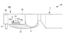
- the ultrasonic therapy apparatus 100 is used in combination with an ultrasonic endoscope 10 that observes a treatment area of a pancreas from a stomach wall.
- the ultrasonic therapy apparatus 100 is attached to the distal end of an elongated insertion portion 1 inserted into a subject of the ultrasonic endoscope 10 together with the diagnostic ultrasonic element 3. ing.
- the insertion unit 1 includes a light guide 5 that guides illumination light for acquiring an observation image, and an objective lens that collects light returning from the observation region irradiated with the illumination light. 7 and a treatment instrument channel 9 through which a treatment instrument such as a puncture needle or forceps is passed.
- the ultrasonic treatment apparatus 100 includes a concave treatment ultrasonic transducer (ultrasonic transducer) that generates therapeutic ultrasonic waves (ultrasonic waves).
- a concave treatment ultrasonic transducer (ultrasonic transducer) that generates therapeutic ultrasonic waves (ultrasonic waves).
- a focal position changing unit 13 that changes the focal position of the therapeutic ultrasonic transducer 11
- an elongated housing 15 that accommodates the therapeutic ultrasonic transducer 11 and the focal position changing unit 13, and treatment from the housing 15
- An anchor 17 that can be projected and retracted in the direction in which therapeutic ultrasonic waves are emitted by the ultrasonic transducer 11, a retracting mechanism 19 that moves the anchor 17 in and out, and therapeutic ultrasonic waves emitted from the therapeutic ultrasonic transducer 11 in the body cavity.
- a balloon (ultrasonic wave propagation part) 21 capable of propagating to the surface.
- the therapeutic ultrasonic transducer 11 is arranged so that an emission surface for emitting therapeutic ultrasonic waves faces in the same direction as the emission surface of the diagnostic ultrasonic element 3.
- the focal position changing unit 13 can translate the therapeutic ultrasonic transducer 11 in the longitudinal direction of the housing 15 or rotate it in the circumferential direction of the housing 15.
- the housing 15 is disposed at the forefront of the insertion portion 1 of the ultrasonic endoscope 10.
- the housing 15 is provided with an anchor accommodating portion 23 for accommodating the anchor 17 on the distal end side with respect to the therapeutic ultrasonic transducer 11.
- the anchor housing part 23 is open in the emission direction of the therapeutic ultrasonic transducer 11.
- the anchor storage portion 23 can store the anchor 17 in the housing 15 up to the tip thereof.
- the anchor 17 can protrude from the anchor storage portion 23 by a predetermined amount.
- the anchor 17 has a convex shape with an obtuse angle at the tip, and the tip can be embedded in the surface of the body cavity such as the stomach wall.
- the anchor 17 is fixed from the therapeutic ultrasonic transducer 11 by fixing the housing 15 in a positioning state with respect to the surface in the body cavity in a state of protruding from the housing 15. The distance to the surface in the body cavity can be fixed.
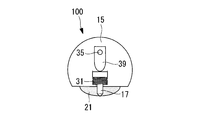
- the intruding mechanism 19 includes a spring 31 that biases the anchor storage portion 23 in the direction in which the anchor 17 is stored, and an anchor that the operator holds and anchors. 17, an anchor operating portion 33 for operating the protrusion / disengagement operation, a flexible shaft 35 for transmitting the operation of the anchor operating portion 33 to the anchor 17, a bearing 37 for rotatably supporting the flexible shaft 35 around its central axis, and a flexible shaft And a cam 39 which is fixed to the distal end portion of 35 and converts the rotational motion of the flexible shaft 35 into the reciprocating motion of the anchor 17.
- the anchor operation portion 33 is disposed on the proximal end side of the housing 15 and is fixed to the proximal end portion of the flexible shaft 35.
- the flexible shaft 35 is disposed along the longitudinal direction through the insertion portion 1 of the ultrasonic endoscope 10.
- the cam 39 rotates around the central axis together with the flexible shaft 35.
- the cam 39 is a plate member whose distance from the central axis to the outer edge is not constant, and comes into contact with the proximal end of the anchor 17 or from the proximal end according to the rotation angle around the central axis of the flexible shaft 35. It is designed to be separated.
- the anchor 17 is pushed out from the anchor housing portion 23 by the cam 39 coming into contact with the base end portion of the anchor 17, and the anchor 39 is separated from the base end portion of the anchor 17 by the urging force of the spring 31.
- An anchor 17 is accommodated in this.
- the ultrasonic treatment apparatus 100 includes a disk 41 with a slit and a photosensor 43 in the housing 15.
- the disk 41 with a slit has a substantially disk shape, and has a slit extending in the radial direction at one place in the circumferential direction.
- the disc 41 with slits is fixed to the tip of the flexible shaft 35.
- the slit-equipped disc 41 rotates around the central axis along with the flexible shaft 35, so that the position of the slit changes around the central axis according to the rotation angle.
- the photo sensor 43 is disposed in the vicinity of the disk 41 with the slit.
- the photosensor 43 outputs an output signal to a not-shown notifying unit when the slit of the disc 41 with slit is detected.
- the notification unit When the output signal is sent from the photosensor 43, the notification unit emits an alarm sound or displays a warning on a monitor screen (not shown). Accordingly, the notification unit can notify the surgeon that the anchor 17 is protruding from the anchor storage unit 23 in conjunction with the movement of the anchor 17 by the anchor operation unit 33. Yes.
- the balloon 21 is attached to the housing 15 so as to cover the exit surfaces of the therapeutic ultrasonic transducer 11 and the diagnostic ultrasonic transducer 3.
- the balloon 21 is inflated in the direction in which ultrasonic waves are emitted from the therapeutic ultrasonic transducer 11 and the diagnostic ultrasonic transducer 3 by injecting and filling an ultrasonic propagation medium such as liquid or gas. It has become.
- an ultrasonic propagation medium such as liquid or gas. It has become.
- the ultrasonic therapy apparatus 100 configured as described above will be described.
- HIFU High Intensity Focused Ultrasound
- the ultrasonic wave propagation medium is not injected into the balloon 21, and the balloon 21 is in a contracted state.
- the anchor 17 is housed in the anchor housing portion 23 of the housing 15. Thereby, the insertion part 1 of the ultrasonic endoscope 10 can be smoothly inserted into the stomach without being obstructed by the balloon 21 or the anchor 17.
- the balloon 21 is inflated by filling the balloon 21 with an ultrasonic wave propagation medium.
- the simple operation of filling the ultrasonic propagation medium and inflating the balloon 21 improves the adhesion between the stomach wall and the diagnostic ultrasonic transducer 3 or the therapeutic ultrasonic transducer 11 and improves the therapeutic efficiency by ultrasonic waves. Can be improved.
- the diagnostic ultrasonic wave is generated from the diagnostic ultrasonic transducer 3 by making the emission surface of the diagnostic ultrasonic transducer 3 face the region to be irradiated with the diagnostic ultrasonic wave.
- the pancreas is observed through the stomach wall based on the echo of the diagnostic ultrasound, and as shown in FIG. 1, the ablation area to be cauterized on the stomach wall corresponding to the treatment site of the pancreas is marked.
- the surgeon operates the anchor operation part 33 to store the anchor 17 in the anchor storage part 23 of the housing 15 as shown in FIGS. 4A and 4B.
- the positioning and fixing of the housing 15 with respect to the stomach wall is released.
- the operator discharges the ultrasonic propagation medium filled in the balloon 21 and contracts the balloon 21.
- the insertion part 1 of the ultrasonic endoscope 10 can be smoothly taken out from the stomach without being obstructed by the anchor 17 or the balloon 21.
- the housing 15 can be moved inside the body cavity without the anchor 17 being stored. It is possible to prevent the housing 15 from being moved or detached from the body cavity.
- the disk 41 with slits and the photosensor 43 are arranged in the housing 15.
- the slit disk 41 and the photosensor 43 may be arranged at the proximal end portion in the insertion portion 1 of the ultrasonic endoscope 10. By doing in this way, size reduction of the housing 15 can be achieved.
- the therapeutic ultrasonic transducer 11 has a concave shape, and the focal position changing unit 13 translates the therapeutic ultrasonic transducer 11 in the longitudinal direction of the housing 15, It was decided to rotate in the circumferential direction.
- the therapeutic ultrasonic transducer 11 has a plurality of piezoelectric elements (ultrasonic elements) 11 a arranged in an array, and the focal position changing unit 13 may selectively activate the piezoelectric element 11a to be used, thereby changing the focal position of the therapeutic ultrasonic transducer 11 to the depth direction of the target region or the direction intersecting the depth direction.
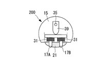
- the ultrasonic therapy apparatus 200 according to the present embodiment is different from the first embodiment in that it includes four anchors 17A, 17B, 17C, and 17D as shown in FIGS. 10A, 10B, and 11.
- portions having the same configuration as those of the sample observation device 100 according to the first embodiment are denoted by the same reference numerals and description thereof is omitted.
- the housing 15 includes two anchor storage portions 23 ⁇ / b> A and 23 ⁇ / b> B disposed at the distal end portion in the longitudinal direction with the therapeutic ultrasonic transducer 11 interposed therebetween, and two anchors disposed at the proximal end portion. It has storage parts 23C and 23D.
- the anchor accommodating portions 23A and 23B at the distal end portion of the housing 15 and the anchor accommodating portions 23C and 23D at the proximal end portion are respectively arranged at intervals in the width direction of the housing 15.
- the four anchors 17A, 17B, 17C, and 17D are provided so as to be able to appear and disappear in the direction in which the ultrasonic wave is emitted from the therapeutic ultrasonic transducer 11 from the respective anchor storage portions 23A, 23B, 23C, and 23D.
- the two anchors 17 ⁇ / b> A and 17 ⁇ / b> B arranged at the distal end portion of the housing 15 are integrated with each other at the base end portion, and the two anchors 17 ⁇ / b> A and 17 ⁇ / b> B are arranged at the base end portion of the housing 15.
- the base ends of the anchors 17C and 17D are integrated with each other.
- the anchors 17A and 17B and the anchors 17C and 17D can move in and out simultaneously.
- the intrusion mechanism 19 includes two ends 37 and 38 and two cams 39 and 40 fixed to the front end of the flexible shaft 35 and the front side thereof.
- One cam 39 is disposed so as to be in contact with the proximal end portions of the pair of anchors 17A and 17B disposed at the distal end portion of the housing 15, and the other cam 40 is disposed at the proximal end portion of the housing 15.
- the anchors 17C and 17D are arranged so as to come into contact with the base ends of the anchors 17C and 17D.
- cams 39 and 40 simultaneously rotate around the central axis along with the flexible shaft 35, and simultaneously contact or separate from the proximal ends of the corresponding anchors 17A and 17B and the proximal ends of the anchors 17C and 17D, respectively. It is supposed to be. Accordingly, the four anchors 17A, 17B, 17C, and 17D can be moved in and out simultaneously according to the rotation angle of the flexible shaft 35.
- the four anchors 17A, 17B, and 4B are arranged in the direction in which the therapeutic ultrasonic wave is emitted from the housing 15 by the operation of the anchor operation unit 33. 17C and 17D protrude at the same time. Therefore, the four anchors 17A, 17B, 17C, and 17D can fix the housing 15 to the surface in the body cavity in a more stable position.
- the four anchors 17A, 17B, 17C, and 17D are simultaneously accommodated in the housing 15 by operating the anchor operation portion 33. Therefore, the housing 15 can be easily and quickly moved without being blocked by the anchors 17A, 17B, 17C, and 17D.
- the four anchors 17A, 17B, 17C, and 17D have been described as examples. However, there may be a plurality of anchors 17, for example, only two disposed at the distal end portion of the housing 15. Also good.
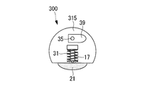
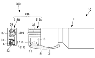
- the ultrasonic therapy apparatus 300 according to the present embodiment is different from the first embodiment in that, instead of the housing 15, as shown in FIGS.
- portions having the same configuration as those of the ultrasonic therapy apparatus 100 according to the first embodiment are denoted by the same reference numerals and description thereof is omitted.
- the housing 315 includes a housing main body 315A including the therapeutic ultrasonic transducer 11 and a housing adapter 315B formed to be connectable to the distal end of the housing main body 315A.
- the housing main body 315A and the housing adapter 315B have housing connecting portions 317A and 317B that are connected to each other.
- the housing adapter 315 ⁇ / b> B includes an anchor storage portion 23, a bearing 37 and a cam 39, and a shaft coupling portion 319 that can be attached to and detached from the distal end of the flexible shaft 35.
- the shaft connecting portion 319 is connected to the tip of the flexible shaft 35.
- a cam 39 is connected to the shaft connecting portion 319. By connecting the shaft connecting portion 319 to the tip of the flexible shaft 35, the cam 39 can be rotated around the central axis along with the flexible shaft 35, and the anchor 17 can be protruded and stored by the cam 39. ing.
- the anchor 17 protrudes from the housing 15 by the operation of the anchor operation unit 33, and the anchor 17 projects into the body cavity.
- the housing 15 is fixed in a positioning state with respect to the surface. Further, by removing the housing adapter 315 ⁇ / b> B from the housing main body 315 ⁇ / b> A, the anchor 17 and the anchor storage portion 23 are detached from the housing 15.
- the entire housing adapter 315B may be replaced. Therefore, the trouble of washing the anchor 17 and the anchor storage part 23 can be saved.
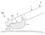
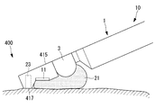
- the ultrasonic treatment apparatus 400 replaces the housing 15 and has a butting surface 417 disposed at a distal end portion in the longitudinal direction so as to be inclined with respect to the longitudinal direction. It differs from 1st Embodiment by the point provided with the housing 415 which has.
- portions having the same configuration as those of the ultrasonic therapy apparatus 100 according to the first embodiment are denoted by the same reference numerals and description thereof is omitted.
- the abutting surface 417 is inclined so that a cross section perpendicular to the longitudinal direction of the housing 415 gradually widens from the distal end surface of the housing 415 toward the base end portion.
- the anchor accommodating portion 23 is opened to the abutting surface 417 and is disposed so as to accommodate the anchor 17 in a direction orthogonal to the abutting surface 417.
- the therapeutic ultrasonic transducer 11 is disposed on the proximal end side with respect to the abutting surface 417, and is inclined so that the emission surface is substantially parallel to the abutting surface 417. As a result, the therapeutic ultrasonic transducer 11 can emit ultrasonic waves in a direction substantially perpendicular to the abutting surface 417.
- the anchor 17 is protruded from the abutting surface 417 in a state where only the abutting surface 417 of the distal end portion of the housing 415 is abutted against the surface in the body cavity.
- the housing 415 is positioned and fixed with respect to the surface in the body cavity by being embedded in the surface in the body cavity. Thereby, the distance from the therapeutic ultrasonic transducer 11 to the surface in the body cavity is fixed.
- the focus of the therapeutic ultrasonic wave is accurately positioned in the target area, and the therapeutic ultrasonic wave is accurately placed at the target position. Can be irradiated.
- the anchor 17 has a tip portion formed in an obtuse angled convex shape.
- the anchor 17 has a clip shape that can grip the surface in the body cavity. It is good also as having a front-end
- Ultrasonic transducer for treatment (ultrasonic transducer) 13 Focal Position Change Part 15 Housing 17 Anchor 21 Balloon (Ultrasonic Propagation Part) 23 Anchor storage (storage) 33 Anchor operation part (operation part) 100, 200, 300, 400 Ultrasonic therapy device 417 Abutting surface
Landscapes
- Health & Medical Sciences (AREA)
- Surgery (AREA)
- Life Sciences & Earth Sciences (AREA)
- Biomedical Technology (AREA)
- Otolaryngology (AREA)
- Engineering & Computer Science (AREA)
- Nuclear Medicine, Radiotherapy & Molecular Imaging (AREA)
- Heart & Thoracic Surgery (AREA)
- Medical Informatics (AREA)
- Molecular Biology (AREA)
- Animal Behavior & Ethology (AREA)
- General Health & Medical Sciences (AREA)
- Public Health (AREA)
- Veterinary Medicine (AREA)
- Surgical Instruments (AREA)
Abstract
治療用超音波の焦点を目標領域に正確に位置決めする。治療用超音波を発生する治療用超音波振動子(11)と、体腔内に挿入可能な細長い形状を有し、治療用超音波振動子(11)を収容するハウジング(15)と、ハウジング(15)に治療用超音波振動子(11)からの治療用超音波の射出方向に出没可能に設けられ、ハウジング(15)から突出した状態で体腔内の表面に対してハウジング(15)を位置決め状態に固定して、治療用超音波振動子(11)から体腔内の表面までの距離を固定可能なアンカー(17)とを備える超音波治療装置(100)を提供する。
Description
本発明は、超音波治療装置に関するものである。
従来、生体における胃の内部などの比較的広い空間内において、病変部に治療用超音波を照射する超音波処置装置が知られている(例えば、特許文献1参照。)。特許文献1に記載の超音波処理装置は、超音波発生源を保持する2つのバルーンを胃などの空間内壁に押し当て、バルーン内の流体量により超音波の照射位置を制御している。
しかしながら、バルーンの形状は、バルーン内の流体量だけで決まるものではなく、空間内壁へのバルーンの押し当て力などによって変化する。そのため、特許文献1に記載の超音波処置装置では、超音波照射の焦点を目標領域に正確に位置決めすることが困難という問題がある。
本発明は、治療用超音波の焦点を目標領域に正確に位置決めすることができる超音波治療装置を提供することを目的としている。
上記目的を達成するために、本発明は以下の手段を提供する。
本発明の一態様は、超音波を発生する超音波振動子と、体腔内に挿入可能な細長い形状を有し、前記超音波振動子を収容するハウジングと、該ハウジングに前記超音波振動子からの超音波の射出方向に出没可能に設けられ、該ハウジングから突出した状態で前記体腔内の表面に対して前記ハウジングを位置決め状態に固定して、前記超音波振動子から前記体腔内の表面までの距離を固定可能なアンカーとを備える超音波治療装置を提供する。
本発明の一態様は、超音波を発生する超音波振動子と、体腔内に挿入可能な細長い形状を有し、前記超音波振動子を収容するハウジングと、該ハウジングに前記超音波振動子からの超音波の射出方向に出没可能に設けられ、該ハウジングから突出した状態で前記体腔内の表面に対して前記ハウジングを位置決め状態に固定して、前記超音波振動子から前記体腔内の表面までの距離を固定可能なアンカーとを備える超音波治療装置を提供する。
本態様によれば、体腔内にハウジングを挿入してアンカーを突出させ、体腔内の所望の位置の表面に対してハウジングを位置決め固定する。これにより、超音波振動子から体腔内の表面までの距離が固定されるので、超音波の焦点を目標領域に正確に位置決めすることができる。したがって、体腔内の所望の位置でアンカーを突出させるだけの簡易な操作で、超音波振動子から発せられる超音波を目標領域に精度よく照射して病変部を治療することができる。
上記態様においては、前記超音波振動子から発せられる超音波を前記体腔内の表面に伝播可能な超音波伝播部を備えることとしてもよい。
このように構成することで、超音波伝播部により、超音波振動子から発せられた超音波が体腔内の表面に伝播されるので、超音波による治療効率の向上を図ることができる。
このように構成することで、超音波伝播部により、超音波振動子から発せられた超音波が体腔内の表面に伝播されるので、超音波による治療効率の向上を図ることができる。
上記態様においては、前記超音波伝播部が、超音波伝播媒体が充填されることにより膨張可能なバルーンであることとしてもよい。
このように構成することで、超音波伝播媒体を充填してバルーンを膨張させるだけの簡易な操作で、体腔内の表面と超音波振動子との密着性を高めて超音波による治療効率を向上させることができる。
このように構成することで、超音波伝播媒体を充填してバルーンを膨張させるだけの簡易な操作で、体腔内の表面と超音波振動子との密着性を高めて超音波による治療効率を向上させることができる。
上記態様においては、前記超音波振動子の焦点位置を変更する焦点位置変更部を備えることとしてもよい。
このように構成することで、焦点位置変更部により、アンカーによって体腔内の表面までの距離が固定された超音波振動子から、目標領域の深さ方向やこれに交差する方向に超音波を照射することができる。したがって、体腔内の大領域に亘る病変部の治療を容易にすることができる。
このように構成することで、焦点位置変更部により、アンカーによって体腔内の表面までの距離が固定された超音波振動子から、目標領域の深さ方向やこれに交差する方向に超音波を照射することができる。したがって、体腔内の大領域に亘る病変部の治療を容易にすることができる。
上記態様においては、前記超音波振動子がアレイ状に配された複数の超音波素子を有し、前記焦点位置変更部が、使用する前記超音波素子を選択することとしてもよい。
このように構成することで、焦点位置変更部により、使用する超音波素子を切り替えるだけの簡易な操作で、超音波の照射範囲を変更することができる。
このように構成することで、焦点位置変更部により、使用する超音波素子を切り替えるだけの簡易な操作で、超音波の照射範囲を変更することができる。
上記態様においては、前記アンカーが前記ハウジングから突出している状態を報知する報知部を備えることとしてもよい。
このように構成することで、ハウジングからアンカーを突出させたままの状態で、体腔内でハウジングを移動したり、また、ハウジングを体腔内に挿入したり体腔内から脱離したりしてしまうのを防止することができる。
このように構成することで、ハウジングからアンカーを突出させたままの状態で、体腔内でハウジングを移動したり、また、ハウジングを体腔内に挿入したり体腔内から脱離したりしてしまうのを防止することができる。
上記態様においては、ユーザが前記アンカーの出没動作を操作する操作部を有し、前記報知部が前記操作部による前記アンカーの出没動作と連動していることとしてもよい。
このように構成することで、アンカーがハウジングから突出している状態であることを確実に報知することができる。
このように構成することで、アンカーがハウジングから突出している状態であることを確実に報知することができる。
上記態様においては、前記ハウジングが、前記アンカーを収納する収納部を着脱可能に有することとしてもよい。
このように構成することで、体腔内の表面に触れて汚れたアンカーや収納部は、洗浄する必要がなくなり、収納部ごと交換すればよい。したがって、アンカーや収納部を洗浄する手間を省くことができる。
このように構成することで、体腔内の表面に触れて汚れたアンカーや収納部は、洗浄する必要がなくなり、収納部ごと交換すればよい。したがって、アンカーや収納部を洗浄する手間を省くことができる。
上記態様においては、前記ハウジングから互いに同時に出没可能な複数の前記アンカーを備えることとしてもよい。
このように構成することで、複数のアンカーにより、体腔内の表面に対してハウジングを安定して位置決め状態に固定することができる。
このように構成することで、複数のアンカーにより、体腔内の表面に対してハウジングを安定して位置決め状態に固定することができる。
上記態様においては、前記ハウジングが、その長手方向の先端部に該長手方向に対して傾斜して配された突き当て面を有し、前記アンカーが、前記突き当て面から該突き当て面に対して略垂直方向に出没可能に設けられ、前記超音波振動子が、前記ハウジングにおける前記突き当て面よりも基端側に配され、前記突き当て面に対して略垂直方向に超音波を射出可能であることとしてもよい。
このように構成することで、体腔内の表面に対してハウジングの先端部の突き当て面を突き当てた状態で、アンカーにより超音波の焦点を目標領域に正確に位置決めすることができる。したがって、体腔内の表面にハウジングを沿わせて配置するのが困難な場合であっても、目標位置に超音波を精度よく照射することができる。
上記態様においては、前記アンカーが、前記体腔内の表面を把持可能なクリップ形状の先端部を有することとしてもよい。
このように構成することで、アンカーの先端部により、体腔内の表面を把持するだけでハウジングを位置決め状態に固定することができ、体腔内の表面に穴を空けずに済む。
このように構成することで、アンカーの先端部により、体腔内の表面を把持するだけでハウジングを位置決め状態に固定することができ、体腔内の表面に穴を空けずに済む。
本発明によれば、治療用超音波の焦点を目標領域に正確に位置決めすることができるという効果を奏する。
〔第1実施形態〕
本発明の第1実施形態に係る超音波治療装置について図面を参照して以下に説明する。
本実施形態に係る超音波治療装置100は、例えば、図1に示すように、胃壁から膵臓の治療領域を観察するような超音波内視鏡10に組み合わされて用いられるようになっている。
本発明の第1実施形態に係る超音波治療装置について図面を参照して以下に説明する。
本実施形態に係る超音波治療装置100は、例えば、図1に示すように、胃壁から膵臓の治療領域を観察するような超音波内視鏡10に組み合わされて用いられるようになっている。
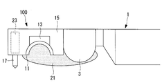
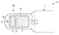
この超音波治療装置100は、例えば、図2Aおよび図2Bに示すように、超音波内視鏡10の被検体内に挿入される細長い挿入部1の先端に診断用超音波素子3と共に取り付けられている。なお、挿入部1には、図3に示すように、観察画像を取得するための照明光を導光するライトガイド5と、照明光が照射された観察領域から戻る光を集光する対物レンズ7と、穿刺針や鉗子のような処置具を通す処置具用チャンネル9が設けられている。
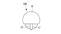
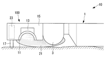
また、超音波治療装置100は、図4A、図4B、図5Aおよび図5Bに示すように、治療用超音波(超音波)を発生する凹面形状の治療用超音波振動子(超音波振動子)11と、治療用超音波振動子11の焦点位置を変更する焦点位置変更部13と、これら治療用超音波振動子11および焦点位置変更部13を収容する細長いハウジング15と、ハウジング15から治療用超音波振動子11による治療用超音波の射出方向に出没可能なアンカー17と、アンカー17を出没動作させる出没機構19と、治療用超音波振動子11から発せられる治療用超音波を体腔内の表面に伝播可能なバルーン(超音波伝播部)21とを備えている。
治療用超音波振動子11は、治療用超音波を射出する射出面を診断用超音波素子3の射出面と同じ方向に向けて配されている。
焦点位置変更部13は、治療用超音波振動子11をハウジング15の長手方向に並進動作させたりハウジング15の周方向に回転動作させたりすることができるようになっている。
焦点位置変更部13は、治療用超音波振動子11をハウジング15の長手方向に並進動作させたりハウジング15の周方向に回転動作させたりすることができるようになっている。
ハウジング15は、超音波内視鏡10の挿入部1の最先端に配置されている。このハウジング15は、治療用超音波振動子11よりも先端側に、アンカー17を収納するアンカー収納部23を備えている。アンカー収納部23は、治療用超音波振動子11の射出方向に開口している。このアンカー収納部23は、ハウジング15内にアンカー17をその先端まで収納することができるようになっている。
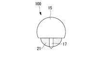
アンカー17は、アンカー収納部23から所定の一定量だけ突出することができるようになっている。このアンカー17は、先端が鈍角の凸形状を有しており、胃壁等、体腔内の表面に先端を埋め込むことができるようになっている。これにより、アンカー17は、図6Aおよび図6Bに示すように、ハウジング15から突出した状態で、体腔内の表面に対してハウジング15を位置決め状態に固定して、治療用超音波振動子11から体腔内の表面までの距離を固定することができるようになっている。
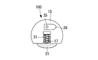
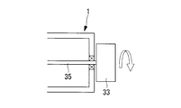
出没機構19は、図4A、図4B、図5A、図5Bおよび図7に示すように、アンカー収納部23にアンカー17を収納する方向に付勢するバネ31と、術者が把持してアンカー17の出没動作を操作するアンカー操作部33と、アンカー操作部33の操作をアンカー17に伝達するフレキシブルシャフト35と、フレキシブルシャフト35をその中心軸線回りに回転可能に支持するベアリング37と、フレキシブルシャフト35の先端部に固定され、フレキシブルシャフト35の回転運動をアンカー17の往復運動に変換するカム39とを備えている。
アンカー操作部33は、図7に示すように、ハウジング15の基端部側に配置され、フレキシブルシャフト35の基端部に固定されている。
フレキシブルシャフト35は、超音波内視鏡10の挿入部1内を通ってその長手方向に沿って配置されている。
フレキシブルシャフト35は、超音波内視鏡10の挿入部1内を通ってその長手方向に沿って配置されている。
カム39は、図4A、図4B、図5Aおよび図5Bに示すように、フレキシブルシャフト35と共に中心軸線回りに回転するようになっている。また、カム39は、中心軸線から外縁部までの距離が一定ではない板部材であり、フレキシブルシャフト35の中心軸線回りの回転角度に応じてアンカー17の基端部に接触したり基端部から離間したりするようになっている。カム39がアンカー17の基端部に接触することでアンカー収納部23からアンカー17が押し出され、カム39がアンカー17の基端部から離間することで、バネ31の付勢力によってアンカー収納部23にアンカー17が収納されるようになっている。
また、超音波治療装置100は、ハウジング15内にスリット付ディスク41と、フォトセンサ43とを有している。
スリット付ディスク41は、略円板形状を有し、周方向の1ヵ所に径方向に延びるスリットを有している。また、スリット付ディスク41は、フレキシブルシャフト35の先端部に固定されている。このスリット付ディスク41は、フレキシブルシャフト35と共に中心軸線回りに回転することで、回転角度に応じてスリットの位置が中心軸線回りに変化するようになっている。
スリット付ディスク41は、略円板形状を有し、周方向の1ヵ所に径方向に延びるスリットを有している。また、スリット付ディスク41は、フレキシブルシャフト35の先端部に固定されている。このスリット付ディスク41は、フレキシブルシャフト35と共に中心軸線回りに回転することで、回転角度に応じてスリットの位置が中心軸線回りに変化するようになっている。
フォトセンサ43は、スリット付ディスク41の近傍に配置されている。このフォトセンサ43は、スリット付ディスク41のスリットを検出すると、図示しない報知部に出力信号を出力するようになっている。
報知部は、フォトセンサ43から出力信号が送られてくると、警報音を発したり図示しないモニタの画面上に警告を表示したりするようになっている。これにより、報知部は、アンカー操作部33によるアンカー17の出没動作に連動して、アンカー収納部23からアンカー17が突出している状態であることを術者に報知することができるようになっている。
バルーン21は、治療用超音波振動子11および診断用超音波振動子3の各射出面を覆うようにハウジング15に装着されている。このバルーン21は、液体や気体等の超音波伝播媒体を注入して充填させることにより、治療用超音波振動子11および診断用超音波振動子3からの超音波の射出方向に膨張するようになっている。バルーン21を膨張させることで、体腔内の表面と治療用超音波振動子11および診断用超音波振動子3との密着性を高め、超音波による診断治療の効率を向上させることができる。
このように構成された超音波治療装置100の作用について説明する。
本実施形態に係る超音波治療装置100により、例えば、膵臓癌をHIFU(High Intensity Focused Ultrasound)治療する場合は、まず、患者の口から食道を通じて胃に超音波内視鏡10の挿入部1を挿入する。
本実施形態に係る超音波治療装置100により、例えば、膵臓癌をHIFU(High Intensity Focused Ultrasound)治療する場合は、まず、患者の口から食道を通じて胃に超音波内視鏡10の挿入部1を挿入する。
このとき、バルーン21には超音波伝播媒体が注入されておらず、バルーン21が収縮した状態になっている。また、アンカー17はハウジング15のアンカー収納部23に収納された状態になっている。これにより、バルーン21やアンカー17によって妨げられることなく、超音波内視鏡10の挿入部1を胃にスムーズに挿入することができる。
胃に挿入部1を挿入したら、図4Aおよび図4Bに示すように、バルーン21内に超音波伝播媒体を充填させてバルーン21を膨張させる。超音波伝播媒体を充填してバルーン21を膨張させるだけの簡易な操作で、胃壁と診断用超音波振動子3や治療用超音波振動子11との密着性を高めて超音波による治療効率を向上させることができる。
次いで、診断用超音波を照射したい領域に診断用超音波振動子3の射出面を対向させて、診断用超音波振動子3から診断用超音波を発生する。そして、診断用超音波のエコーに基づいて胃壁越しに膵臓を観察し、図1に示すように、膵臓の治療部位に対応する胃壁の焼灼すべき焼灼領域をマーキングする。
次いで、術者はアンカー操作部33を操作し、胃壁にマーキングしてある焼灼領域に対してバルーン21を接触させた状態で、図5Aおよび図5Bに示すように、ハウジング15からアンカー17を突出させる。そして、図6Aおよび図6Bに示すように、胃壁の表面にアンカー17の先端を埋め込み、胃壁に対してハウジング15を位置決め固定する。これにより、治療用超音波振動子11から胃壁の表面までの距離が固定されるので、治療用超音波の焦点を目標領域に正確に位置決めすることができる。
次いで、治療用超音波振動子11により治療用超音波を焼灼領域に照射し、焼灼領域を高温灼熱して治療する。術者は、焦点位置変更部13により、治療用超音波振動子11の焦点位置を変更することで、アンカー17によって治療用超音波振動子11から胃壁までの距離が固定されている状態で、目標領域の深さ方向や深さ方向に交差する方向に治療用超音波を照射することができる。したがって、体腔内の大領域に亘る病変部の治療を容易にすることができる。
病変部の治療が終了したら、術者はアンカー操作部33を操作して、図4Aおよび図4Bに示すように、ハウジング15のアンカー収納部23にアンカー17を収納する。これにより、胃壁に対するハウジング15の位置決め固定が解除される。また、術者はバルーン21内に充填されている超音波伝播媒体を排出してバルーン21を収縮させる。これにより、アンカー17やバルーン21によって妨げられることなく、超音波内視鏡10の挿入部1を胃からスムーズに取り出することができる。
このとき、ハウジング15からアンカー17が突出している状態であれば、報知部により警報音や警告表示が術者に報知されるので、アンカー17を収納していない状態で、体腔内でハウジング15を移動したり体腔内からハウジング15を脱離したりしてしまうのを防止することができる。
以上説明したように本実施形態に係る超音波治療装置100によれば、体腔内の所望の位置でアンカー17を突出させるだけの簡易な操作で、治療用超音波の焦点を目標領域に正確に位置決めすることができる。これにより、治療用超音波振動子11から発せられる治療用超音波を目標領域に精度よく照射して病変部を治療することができる。
本実施形態においては、スリット付ディスク41およびフォトセンサ43をハウジング15内に配置することとした。これに代えて、例えば、図8に示すように、スリット付ディスク41およびフォトセンサ43を超音波内視鏡10の挿入部1内の基端部に配置することとしてもよい。このようにすることで、ハウジング15の小型化を図ることができる。
また、本実施形態においては、治療用超音波振動子11が凹面形状を有し、焦点位置変更部13が、治療用超音波振動子11をハウジング15の長手方向に並進動作させたりハウジング15の周方向に回転動作させたりすることとした。これに代えて、例えば、図9Aおよび図9Bに示すように、治療用超音波振動子11が、アレイ状に配された複数の圧電素子(超音波素子)11aを有し、焦点位置変更部13が、使用する圧電素子11aを選択的に作動させることにより、治療用超音波振動子11の焦点位置を目標領域の深さ方向や深さ方向に交差する方向に変更することとしてもよい。
〔第2実施形態〕
次に、本発明の第2実施形態に係る超音波治療装置について説明する。
本実施形態に係る超音波治療装置200は、図10A、図10Bおよび図11に示すように、4本のアンカー17A,17B,17C,17Dを備える点で第1実施形態と異なる。
以下、第1実施形態に係る標本観察装置100と構成を共通する箇所には、同一符号を付して説明を省略する。
次に、本発明の第2実施形態に係る超音波治療装置について説明する。
本実施形態に係る超音波治療装置200は、図10A、図10Bおよび図11に示すように、4本のアンカー17A,17B,17C,17Dを備える点で第1実施形態と異なる。
以下、第1実施形態に係る標本観察装置100と構成を共通する箇所には、同一符号を付して説明を省略する。
ハウジング15は、図11に示すように、治療用超音波振動子11を挟んで長手方向の先端部に配された2つのアンカー収納部23A,23Bと、基端部に配された2つのアンカー収納部23C,23Dとを有している。これらハウジング15の先端部のアンカー収納部23A,23Bどうし、および、基端部のアンカー収納部23C,23Dどうしは、それぞれハウジング15の幅方向に間隔を空けて配されている。
4本のアンカー17A,17B,17C,17Dは、それぞれ各アンカー収納部23A,23B,23C,23Dから治療用超音波振動子11による超音波の射出方向に出没可能に設けられている。また、図10Aに示すように、ハウジング15の先端部に配されている2つのアンカー17A,17Bどうしは互いに基端部が一体化しており、ハウジング15の基端部に配されている2つのアンカー17C,17Dどうしも互いに基端部が一体化している。これにより、アンカー17A,17Bどうしおよびアンカー17C,17Dどうしは、それぞれ同時に出没動作することができるようになっている。
出没機構19は、フレキシブルシャフト35の先端とその手前に固定された2つのベアリング37,38および2つのカム39,40を備えている。一方のカム39は、ハウジング15の先端部に配される1組のアンカー17A,17Bの基端部に接触可能に配され、他方のカム40はハウジング15の基端部に配されるもう1組のアンカー17C,17Dの基端部に接触可能に配されている。
これらカム39,40は、フレキシブルシャフト35と共に中心軸線回りに同時に回転して、それぞれ対応するアンカー17A,17Bの基端部およびアンカー17C,17Dの基端部に対して同時に接触したり離間したりするようになっている。これにより、フレキシブルシャフト35の回転角度に応じて4本のアンカー17A,17B,17C,17Dを同時に出没動作させることができるようになっている。
このように構成された超音波治療装置200によれば、アンカー操作部33の操作により、ハウジング15から治療用超音波振動子11による治療用超音波の射出方向に4本のアンカー17A,17B,17C,17Dが同時に突出する。したがって、4本のアンカー17A,17B,17C,17Dにより、体腔内の表面に対してハウジング15をより安定して位置決め状態に固定することができる。
また、アンカー操作部33を操作により、4本のアンカー17A,17B,17C,17Dがハウジング15に同時に収納される。したがって、アンカー17A,17B,17C,17Dによって妨げられることなく、ハウジング15を容易かつ迅速に移動させることができる。
本実施形態においては、4本のアンカー17A,17B,17C,17Dを例示して説明したが、アンカー17が複数本あればよく、例えば、ハウジング15の先端部に配置する2本のみであってもよい。
〔第3実施形態〕
次に、本発明の第3実施形態に係る超音波治療装置について説明する。
本実施形態に係る超音波治療装置300は、ハウジング15に代えて、図12Aおよび図12Bに示すように、アンカー収納部23を着脱可能に有するハウジング315を備える点で第1実施形態と異なる。
以下、第1実施形態に係る超音波治療装置100と構成を共通する箇所には、同一符号を付して説明を省略する。
次に、本発明の第3実施形態に係る超音波治療装置について説明する。
本実施形態に係る超音波治療装置300は、ハウジング15に代えて、図12Aおよび図12Bに示すように、アンカー収納部23を着脱可能に有するハウジング315を備える点で第1実施形態と異なる。
以下、第1実施形態に係る超音波治療装置100と構成を共通する箇所には、同一符号を付して説明を省略する。
ハウジング315は、治療用超音波振動子11を備えるハウジング本体部315Aと、ハウジング本体部315Aの先端に連結可能に形成されたハウジングアダプタ315Bとにより構成されている。これらハウジング本体部315Aおよびハウジングアダプタ315Bは、互いに連結するハウジング連結部317A,317Bを有している。
ハウジングアダプタ315Bは、アンカー収納部23と、ベアリング37およびカム39と、フレキシブルシャフト35の先端に対して着脱可能なシャフト連結部319とを備えている。ハウジング連結部317によりハウジング本体部315Aとハウジングアダプタ315Bとを連結した状態で、フレキシブルシャフト35の先端にシャフト連結部319が連結されるようになっている。
シャフト連結部319にはカム39が接続されている。フレキシブルシャフト35の先端にシャフト連結部319を連結することで、フレキシブルシャフト35と共に中心軸線回りにカム39を回転させて、カム39によりアンカー17を突出させたり収納させたりすることができるようになっている。
このように構成された超音波治療装置300によれば、ハウジング本体部315Aにハウジングアダプタ315Bを連結することで、アンカー操作部33の操作によりハウジング15からアンカー17が突出し、アンカー17により体腔内の表面に対してハウジング15が位置決め状態に固定される。また、ハウジング本体部315Aからハウジングアダプタ315Bを取り外すことで、ハウジング15からアンカー17およびアンカー収納部23が脱離される。
したがって、アンカー17およびアンカー収納部23のみを交換することができる。これにより、アンカー17やアンカー収納部23が体腔内の表面に触れて汚れた場合は、ハウジングアダプタ315Bごと交換すればよい。よって、アンカー17やアンカー収納部23を洗浄する手間を省くことができる。
〔第4実施形態〕
次に、本発明の第4実施形態に係る超音波治療装置について説明する。
本実施形態に係る超音波治療装置400は、図13および図14に示すように、ハウジング15に代えて、長手方向の先端部にその長手方向に対して傾斜して配された突き当て面417を有するハウジング415を備える点で第1実施形態と異なる。
以下、第1実施形態に係る超音波治療装置100と構成を共通する箇所には、同一符号を付して説明を省略する。
次に、本発明の第4実施形態に係る超音波治療装置について説明する。
本実施形態に係る超音波治療装置400は、図13および図14に示すように、ハウジング15に代えて、長手方向の先端部にその長手方向に対して傾斜して配された突き当て面417を有するハウジング415を備える点で第1実施形態と異なる。
以下、第1実施形態に係る超音波治療装置100と構成を共通する箇所には、同一符号を付して説明を省略する。
突き当て面417は、ハウジング415の先端面から基端部に向かって、ハウジング415の長手方向に垂直な断面が徐々に広がるように傾斜している。
アンカー収納部23は、突き当て面417に開口し、突き当て面417に対して直交する方向にアンカー17を収納可能に配置されている。
アンカー収納部23は、突き当て面417に開口し、突き当て面417に対して直交する方向にアンカー17を収納可能に配置されている。
治療用超音波振動子11は、突き当て面417よりも基端側に配され、射出面が突き当て面417と略平行になるように傾けられている。これにより、治療用超音波振動子11は、突き当て面417に対して略垂直方向に超音波を射出することができるようになっている。
このように構成された超音波治療装置400によれば、体腔内の表面に対してハウジング415の先端部の突き当て面417のみを突き当てた状態で、突き当て面417からアンカー17を突出させて体腔内の表面に埋め込むことで、体腔内の表面に対してハウジング415が位置決め固定される。これにより、治療用超音波振動子11から体腔内の表面までの距離が固定される。
したがって、体腔内の表面にハウジング415を沿わせて配置するのが困難な場合であっても、治療用超音波の焦点を目標領域に正確に位置決めし、目標位置に治療用超音波を精度よく照射することができる。
以上、本発明の実施形態について図面を参照して詳述してきたが、具体的な構成はこの実施形態に限られるものではなく、本発明の要旨を逸脱しない範囲の設計変更等も含まれる。例えば、本発明を上記各実施形態および変形例に適用したものに限定されることなく、これらの実施形態および変形例を適宜組み合わせた実施形態に適用してもよく、特に限定されるものではない。
また、例えば、上記各実施形態においては、アンカー17が鈍角の凸形状に形成された先端部を有することとしたが、これに代えて、アンカー17が、体腔内の表面を把持可能なクリップ形状の先端部を有することとしてもよい。このようにすることで、アンカー17の先端部により、体腔内の表面を把持してハウジング15を位置決め状態に固定することができ、体腔内の表面に穴を空けずに済む。
11 治療用超音波振動子(超音波振動子)
13 焦点位置変更部
15 ハウジング
17 アンカー
21 バルーン(超音波伝播部)
23 アンカー収納部(収納部)
33 アンカー操作部(操作部)
100,200,300,400 超音波治療装置
417 突き当て面
13 焦点位置変更部
15 ハウジング
17 アンカー
21 バルーン(超音波伝播部)
23 アンカー収納部(収納部)
33 アンカー操作部(操作部)
100,200,300,400 超音波治療装置
417 突き当て面
Claims (11)
- 超音波を発生する超音波振動子と、
体腔内に挿入可能な細長い形状を有し、前記超音波振動子を収容するハウジングと、
該ハウジングに前記超音波振動子からの超音波の射出方向に出没可能に設けられ、該ハウジングから突出した状態で前記体腔内の表面に対して前記ハウジングを位置決め状態に固定して、前記超音波振動子から前記体腔内の表面までの距離を固定可能なアンカーとを備える超音波治療装置。 - 前記超音波振動子から発せられる超音波を前記体腔内の表面に伝播可能な超音波伝播部を備える請求項1に記載の超音波治療装置。
- 前記超音波伝播部が、超音波伝播媒体が充填されることにより膨張可能なバルーンである請求項2に記載の超音波治療装置。
- 前記超音波振動子の焦点位置を変更する焦点位置変更部を備える請求項1から請求項3のいずれかに記載の超音波治療装置。
- 前記超音波振動子がアレイ状に配された複数の超音波素子を有し、
前記焦点位置変更部が、使用する前記超音波素子を選択する請求項4に記載の超音波治療装置。 - 前記アンカーが前記ハウジングから突出している状態を報知する報知部を備える請求項1から請求項5のいずれかに記載の超音波治療装置。
- ユーザが前記アンカーの出没動作を操作する操作部を有し、
前記報知部が前記操作部による前記アンカーの出没動作と連動している請求項6に記載の超音波治療装置。 - 前記ハウジングが、前記アンカーを収納する収納部を着脱可能に有する請求項1から請求項7に記載の超音波治療装置。
- 前記ハウジングから互いに同時に出没可能な複数の前記アンカーを備える請求項1から請求項8に記載の超音波治療装置。
- 前記ハウジングが、その長手方向の先端部に該長手方向に対して傾斜して配された突き当て面を有し、
前記アンカーが、前記突き当て面から該突き当て面に対して略垂直方向に出没可能に設けられ、
前記超音波振動子が、前記ハウジングにおける前記突き当て面よりも基端側に配され、前記突き当て面に対して略垂直方向に超音波を射出可能である請求項1から請求項9のいずれかに記載の超音波治療装置。 - 前記アンカーが、前記体腔内の表面を把持可能なクリップ形状の先端部を有する請求項1から請求項10のいずれかに記載の超音波治療装置。
Applications Claiming Priority (2)
| Application Number | Priority Date | Filing Date | Title |
|---|---|---|---|
| JP2014145749A JP2016021982A (ja) | 2014-07-16 | 2014-07-16 | 超音波治療装置 |
| JP2014-145749 | 2014-07-16 |
Publications (1)
| Publication Number | Publication Date |
|---|---|
| WO2016009671A1 true WO2016009671A1 (ja) | 2016-01-21 |
Family
ID=55078176
Family Applications (1)
| Application Number | Title | Priority Date | Filing Date |
|---|---|---|---|
| PCT/JP2015/057112 Ceased WO2016009671A1 (ja) | 2014-07-16 | 2015-03-11 | 超音波治療装置 |
Country Status (2)
| Country | Link |
|---|---|
| JP (1) | JP2016021982A (ja) |
| WO (1) | WO2016009671A1 (ja) |
Citations (6)
| Publication number | Priority date | Publication date | Assignee | Title |
|---|---|---|---|---|
| JPS62231651A (ja) * | 1986-03-31 | 1987-10-12 | 株式会社東芝 | 生体治療装置 |
| JPH07227395A (ja) * | 1993-12-24 | 1995-08-29 | Olympus Optical Co Ltd | 超音波診断治療システム |
| US5492119A (en) * | 1993-12-22 | 1996-02-20 | Heart Rhythm Technologies, Inc. | Catheter tip stabilizing apparatus |
| US20090312755A1 (en) * | 2008-06-13 | 2009-12-17 | Vytronus, Inc. | System and method for positioning an elongate member with respect to an anatomical structure |
| JP2012090778A (ja) * | 2010-10-27 | 2012-05-17 | Olympus Corp | 超音波照射デバイス |
| JP2014176429A (ja) * | 2013-03-13 | 2014-09-25 | Olympus Corp | 経体腔式焼灼デバイス |
-
2014
- 2014-07-16 JP JP2014145749A patent/JP2016021982A/ja active Pending
-
2015
- 2015-03-11 WO PCT/JP2015/057112 patent/WO2016009671A1/ja not_active Ceased
Patent Citations (6)
| Publication number | Priority date | Publication date | Assignee | Title |
|---|---|---|---|---|
| JPS62231651A (ja) * | 1986-03-31 | 1987-10-12 | 株式会社東芝 | 生体治療装置 |
| US5492119A (en) * | 1993-12-22 | 1996-02-20 | Heart Rhythm Technologies, Inc. | Catheter tip stabilizing apparatus |
| JPH07227395A (ja) * | 1993-12-24 | 1995-08-29 | Olympus Optical Co Ltd | 超音波診断治療システム |
| US20090312755A1 (en) * | 2008-06-13 | 2009-12-17 | Vytronus, Inc. | System and method for positioning an elongate member with respect to an anatomical structure |
| JP2012090778A (ja) * | 2010-10-27 | 2012-05-17 | Olympus Corp | 超音波照射デバイス |
| JP2014176429A (ja) * | 2013-03-13 | 2014-09-25 | Olympus Corp | 経体腔式焼灼デバイス |
Also Published As
| Publication number | Publication date |
|---|---|
| JP2016021982A (ja) | 2016-02-08 |
Similar Documents
| Publication | Publication Date | Title |
|---|---|---|
| JP5912134B2 (ja) | 光コヒーレンストモグラフィ、照明又は光凝固について組み合わされた手術エンドプローブ | |
| US10631930B1 (en) | Ablation system and ablation device | |
| JP5690343B2 (ja) | 超音波診断装置、システム及び作動方法 | |
| JP6266557B2 (ja) | 内視鏡 | |
| KR101093734B1 (ko) | 초음파 치료기용 헤드, 초음파 치료기 및 초음파 치료기의 동작 방법 | |
| WO2019070632A1 (en) | METHOD AND APPARATUS FOR ADMINISTERING STIMULUS TO OCCLUSIVE IMPLANT | |
| JP2007029603A (ja) | 光診断治療装置 | |
| US20190125447A1 (en) | Apparatus and methods for resecting and/or ablating an undesired tissue | |
| JP2016174820A (ja) | 内視鏡 | |
| WO2012102099A1 (ja) | 処置具 | |
| US20190053821A1 (en) | Ultrasound ablation device | |
| JP3850094B2 (ja) | 超音波診断治療システムおよび治療用アダプタ | |
| JP2015058234A (ja) | 医療用液体噴射装置 | |
| JP5602798B2 (ja) | 処置具挿通用チューブ、内視鏡フード及び内視鏡キャップ | |
| JPH07227395A (ja) | 超音波診断治療システム | |
| WO2016009671A1 (ja) | 超音波治療装置 | |
| JP2014140460A (ja) | 超音波内視鏡 | |
| JP2014176429A (ja) | 経体腔式焼灼デバイス | |
| JP2949783B2 (ja) | 体腔内処置装置 | |
| WO2014045677A1 (ja) | 生検針および生検システム | |
| JP6842399B2 (ja) | レーザチップ、レーザ処置具、レーザ治療装置、及びレーザ治療システム | |
| JP4864603B2 (ja) | 超音波内視鏡 | |
| JP2005192945A (ja) | 超音波処置用医療装置 | |
| JP2014226472A (ja) | 治療用超音波アダプタおよび超音波治療装置 | |
| JP2007307289A (ja) | 超音波内視鏡装置 |
Legal Events
| Date | Code | Title | Description |
|---|---|---|---|
| 121 | Ep: the epo has been informed by wipo that ep was designated in this application |
Ref document number: 15822882 Country of ref document: EP Kind code of ref document: A1 |
|
| NENP | Non-entry into the national phase |
Ref country code: DE |
|
| 122 | Ep: pct application non-entry in european phase |
Ref document number: 15822882 Country of ref document: EP Kind code of ref document: A1 |