WO2016006446A1 - 道路照明灯具 - Google Patents
道路照明灯具 Download PDFInfo
- Publication number
- WO2016006446A1 WO2016006446A1 PCT/JP2015/068189 JP2015068189W WO2016006446A1 WO 2016006446 A1 WO2016006446 A1 WO 2016006446A1 JP 2015068189 W JP2015068189 W JP 2015068189W WO 2016006446 A1 WO2016006446 A1 WO 2016006446A1
- Authority
- WO
- WIPO (PCT)
- Prior art keywords
- bottom plate
- led
- illumination lamp
- clip
- fixed
- Prior art date
- Legal status (The legal status is an assumption and is not a legal conclusion. Google has not performed a legal analysis and makes no representation as to the accuracy of the status listed.)
- Ceased
Links
Images





Classifications
-
- F—MECHANICAL ENGINEERING; LIGHTING; HEATING; WEAPONS; BLASTING
- F21—LIGHTING
- F21S—NON-PORTABLE LIGHTING DEVICES; SYSTEMS THEREOF; VEHICLE LIGHTING DEVICES SPECIALLY ADAPTED FOR VEHICLE EXTERIORS
- F21S8/00—Lighting devices intended for fixed installation
- F21S8/08—Lighting devices intended for fixed installation with a standard
-
- F—MECHANICAL ENGINEERING; LIGHTING; HEATING; WEAPONS; BLASTING
- F21—LIGHTING
- F21V—FUNCTIONAL FEATURES OR DETAILS OF LIGHTING DEVICES OR SYSTEMS THEREOF; STRUCTURAL COMBINATIONS OF LIGHTING DEVICES WITH OTHER ARTICLES, NOT OTHERWISE PROVIDED FOR
- F21V19/00—Fastening of light sources or lamp holders
-
- F—MECHANICAL ENGINEERING; LIGHTING; HEATING; WEAPONS; BLASTING
- F21—LIGHTING
- F21V—FUNCTIONAL FEATURES OR DETAILS OF LIGHTING DEVICES OR SYSTEMS THEREOF; STRUCTURAL COMBINATIONS OF LIGHTING DEVICES WITH OTHER ARTICLES, NOT OTHERWISE PROVIDED FOR
- F21V29/00—Protecting lighting devices from thermal damage; Cooling or heating arrangements specially adapted for lighting devices or systems
- F21V29/50—Cooling arrangements
- F21V29/502—Cooling arrangements characterised by the adaptation for cooling of specific components
- F21V29/503—Cooling arrangements characterised by the adaptation for cooling of specific components of light sources
-
- F—MECHANICAL ENGINEERING; LIGHTING; HEATING; WEAPONS; BLASTING
- F21—LIGHTING
- F21V—FUNCTIONAL FEATURES OR DETAILS OF LIGHTING DEVICES OR SYSTEMS THEREOF; STRUCTURAL COMBINATIONS OF LIGHTING DEVICES WITH OTHER ARTICLES, NOT OTHERWISE PROVIDED FOR
- F21V29/00—Protecting lighting devices from thermal damage; Cooling or heating arrangements specially adapted for lighting devices or systems
- F21V29/50—Cooling arrangements
- F21V29/70—Cooling arrangements characterised by passive heat-dissipating elements, e.g. heat-sinks
- F21V29/74—Cooling arrangements characterised by passive heat-dissipating elements, e.g. heat-sinks with fins or blades
Definitions
- the present invention relates to a road illumination lamp.
- a road illumination lamp that is attached to, for example, the upper end of a pole and illuminates a road from above is known (for example, see Patent Documents 1 and 2).
- a substrate on which a light emitting element for example, a light emitting diode chip
- a bottom plate on which a plurality of fins are erected heat generated from the light emitting element is generated by the fin. Is supposed to be dissipated.
- This invention was made in order to solve the said subject, and it aims at provision of the road illumination lamp which can fix suitably a board
- a road illumination lamp comprising an LED board on which an LED is mounted, and a bottom plate on which a plurality of fins are erected on one side and the LED board is fixed on the other side, The LED substrate and the bottom plate are fixed to each other by pressing a peripheral edge with a clip.
- the invention according to claim 2 is the road illumination lamp according to claim 1, Among the clips, a pressing portion that presses the one surface of the bottom plate is formed to be insertable between the plurality of fins erected on the one surface.
- the invention according to claim 3 is the road illumination lamp according to claim 1 or 2, A lens member for controlling light distribution from the LED;
- the clip is characterized in that the lens member, the LED board, and the bottom plate are fastened together.
- the LED substrate on which the LED is mounted and the bottom plate on which the plurality of fins are erected are pressed and fixed to each other with the clip.
- the bottom plate and the LED substrate can be fixed even when the bottom plate is thinned to enhance the heat dissipation effect. Therefore, the LED substrate and the bottom plate can be suitably fixed while improving the heat dissipation effect by the fins.
- the press part which presses one surface of a baseplate among clips is formed so that it can insert between the several fins standingly arranged by the said one surface. Accordingly, the LED substrate and the bottom plate can be pressed and fixed in a state where the pressing portion of the clip is inserted between the plurality of fins, so that the fin can be formed to the full width of the bottom plate without having to escape from the clip. Therefore, the LED substrate and the bottom plate can be suitably fixed while further improving the heat dissipation effect by the fins.
- FIG. 4B is a sectional view taken along line VII-VII in FIG. 4A.
- FIG. 1 is a view showing a state in which the road illumination lamp 1 according to the present embodiment is attached to a pole 100 described later
- FIG. 2 is a perspective view of the road illumination lamp 1
- FIG. FIG. 1 is a view showing a state in which the road illumination lamp 1 according to the present embodiment is attached to a pole 100 described later
- FIG. 2 is a perspective view of the road illumination lamp 1
- FIG. FIG. 1 is a view showing a state in which the road illumination lamp 1 according to the present embodiment is attached to a pole 100 described later
- FIG. 2 is a perspective view of the road illumination lamp 1
- the road illumination lamp 1 is provided at the upper end of a two-lamp pole 100, for example, and illuminates a road on which a vehicle (automobile) (not shown) travels from above.
- the pole 100 that supports the road illumination lamp 1 is formed in a Y shape with its upper portion branched, and the two booms 110 that are the branched portions are inclined obliquely upward, respectively.
- the road illumination lamp 1 is attached to each front end portion downward.
- the road illumination lamp 1 is arrange
- the road illumination lamp 1 is formed in a slightly long flat shape, and its longitudinal direction X is substantially along the width direction of the road, and the longitudinal direction X Is arranged so that the width direction Y orthogonal to the vehicle travel direction.
- the road illumination lamp 1 includes a main frame 2 and a cover 3, two power supply units 4 and 4, and two illumination modules 5 in a lamp chamber formed by the main frame 2 and the cover 3. , 5 are accommodated.
- the main frame 2 is a component that mainly supports the two power supply units 4 and 4 and the two lighting modules 5 and 5.
- the main frame 2 has a skeleton 21 that retains the strength required for the main frame 2.
- the skeleton part 21 is formed over substantially the entire length of the main frame 2 along the longitudinal direction X, and standing walls 25 for attaching the cover 3 are respectively provided on both ends thereof.
- One end side (hereinafter referred to as “base end side”) in the longitudinal direction X of the skeleton portion 21 is a pole fixing portion 22 to which the boom 110 of the pole 100 is fixed.
- the pole fixing portion 22 has a V-shaped pole receiving groove 221 along the longitudinal direction X, and has a pole abutting portion 222 at the end on the tip side.
- the boom 110 of the pole 100 is inserted into an insertion hole 25a formed in the upright wall 25 on the proximal end side, and is fitted in the pole receiving groove 221 with the front end face being abutted against the pole abutting portion 222.
- the U-shaped bolts 61 and 61 and a nut (not shown) are fastened and fixed to the pole fixing portion 22.
- the skeleton part 21 the part on the other end side in the longitudinal direction X (hereinafter referred to as “tip side”) with respect to the pole fixing part 22 is a main skeleton formed with a slightly narrower width than the pole fixing part 22. It becomes part 23.
- the main skeleton portion 23 is a portion that supports the two power supply units 4 and 4 and the two illumination modules 5 and 5.
- each module support portion 24 is formed in a frame shape that supports only the peripheral edge portion of the light emitting portion so that the light emitting portion (lens plate 53 described later) of the illumination module 5 to be supported is exposed downward. Has been.
- the cover 3 is a lid part of the road illumination lamp 1 and is formed of a thin aluminum plate.
- the cover 3 is attached to the two standing walls 25 and 25 of the main frame 2 at both ends in the longitudinal direction X.
- an opening is formed between the cover 3 and the main frame 2 at both sides in the width direction Y from each standing wall 25, and the opening serves as a ventilation hole for radiating heat from the two illumination modules 5 and 5.
- the two power supply units 4 and 4 are arranged side by side in the vertical direction with a plurality of spacers 41 interposed therebetween, and are fixed to the main skeleton portion 23 of the main frame 2. These two power supply units 4 and 4 correspond to the two illumination modules 5 and 5, and are electrically connected so as to individually supply power to the two illumination modules 5 and 5.
- each illumination module 5 includes two LED (light emitting diode) units 51 and 51 and a heat dissipation unit 54.
- the two LED units 51 and 51 are each comprised from the LED board 52 in which several LED520, ... was mounted, and the lens board 53 for controlling light distribution from several LED520, .... Yes.
- the LED substrate 52 and the lens plate 53 are formed to have substantially the same size, and are overlapped with their four sides aligned. Further, a plurality of locking grooves 53a for locking a first locking portion 551a of a clip 55 to be described later are formed at both ends in the width direction of the lens plate 53.
- the heat dissipation unit 54 is configured such that a plurality of fin plates 542,... Are fixed to the back surface of a long bottom plate 541.
- the bottom plate 541 is formed of an aluminum flat plate.
- the bottom plate 541 has a thin plate thickness (about 1 in this embodiment). .2 mm).
- a plurality of locking holes 541a for locking a second locking portion 552a of a clip 55 described later are formed.
- the locking hole 541 a is provided at a position substantially corresponding to the locking groove 53 a of the lens plate 53.
- Each fin plate 542 is a thin aluminum plate formed into a U-shaped sheet metal, and is fixed to the bottom plate 541 with its opening side facing away from the bottom plate 541. That is, each fin plate 542 has a shape in which two fins 542a and 542a having a predetermined interval are connected by the connecting portion 542b therebetween.
- the plurality of fin plates 542,... are arranged along the longitudinal direction of the bottom plate 541 so that two adjacent fins 542a, 542a are at the predetermined interval. However, in the longitudinal center of the bottom plate 541 located between the two LED units 51, 51, a slightly wider gap is provided between the two adjacent fin plates 542, 542.
- the bottom plate 541 and the fin plates 542 are fixed by so-called dowel caulking.
- the bottom plate 541 and each fin plate 542 are inserted through a dowel (not shown) protruding from the back side of the bottom plate 541 into a lower hole 542c formed in the connecting portion 542b of the fin plate 542,
- the fin plate 542 and the bottom plate 541 are caulked and fixed by crushing the head of the dowel with a jig.
- the plurality of fins 542a,... Are erected on the back surface of the bottom plate 541.
- each LED unit 51 and the heat radiating unit 54 are pressed and fixed to each other by a plurality of clips 55.
- 6A, 6B, and 6C are a top view, a side view, and a bottom view of the clip 55
- FIG. 7 is a cross-sectional view taken along the line VII-VII of FIG. It is a figure for doing.
- the clip 55 is made of a plate-like elastic material formed in a substantially U shape, and sandwiches the LED unit 51 and the heat dissipation unit 54 with its elastic force. Press and fix to.
- a first locking portion 551 a is formed at the tip of the first pressing portion 551 that presses the LED unit 51.
- the first locking portion 551 a protrudes inside the clip 55 from the first pressing portion 551.
- the second pressing portion 552 that presses the heat dissipation unit 54 is divided into a plurality (three in this embodiment) by partially notching.
- the plurality of second pressing portions 552,... are formed with predetermined widths and intervals so that they can be inserted between the fins 542a,.
- a second locking portion 552 a is formed at the tip of the second pressing portion 552 so as to project from the second pressing portion 552 to the inside of the clip 55.
- the clip 55 presses and fixes the LED unit 51 and the heat radiating unit 54 so that the LED substrate 52 is brought into close contact with the surface of the bottom plate 541. More specifically, the lens plate 53 of the LED unit 51 is pressed by the first pressing portion 551, and the bottom plate 541 of the heat radiating unit 54 is pressed by the second pressing portion 552, so that the LED substrate 52 is sandwiched between these lenses. The plate 53, the LED substrate 52, and the bottom plate 541 are fastened together. At this time, the first locking portion 551a of the first pressing portion 551 is locked to the locking groove 53a of the lens plate 53, and the second locking portion 552a of the second pressing portion 552 is locked to the locking hole 541a of the bottom plate 541. The clip 55 is prevented from falling off.
- the LED substrate 52 on which the plurality of LEDs 520,... are mounted and the bottom plate 541 on which the plurality of fins 542a,.
- the part is pressed and fixed by a clip 55.
- the bottom plate 541 and the LED substrate 52 can be fixed even when the bottom plate 541 is thinned to enhance the heat dissipation effect. . Therefore, it is possible to suitably fix the LED substrate 52 and the bottom plate 541 while improving the heat dissipation effect by the fins 542a.
- the 2nd press part 552 which presses the back surface of the baseplate 541 among the clips 55 is formed so that insertion is possible between the several fins 542a, ... standingly arranged by the said back surface. Accordingly, the LED substrate 52 and the bottom plate 541 can be pressed and fixed in a state where the second pressing portion 552 of the clip 55 is inserted between the plurality of fins 542a,..., So that the bottom plate 541 does not need to be released from the clip 55. It can be formed widely up to the full width. Therefore, the LED substrate 52 and the bottom plate 541 can be suitably fixed while further improving the heat dissipation effect by the fins 542a.
- the second pressing portion 552 of the clip 55 can be inserted between the plurality of fins 542a,.
- the quantity is not particularly limited.
- the road illumination lamp 1 is provided with the two power supply units 4 and the illumination module 5, these quantities are not particularly limited.
- the road illumination lamp 1 is supposed to be attached to the pole 100, the road illumination lamp according to the present invention is not limited to the one attached to the pole (post) as long as it can illuminate the road from above.
- it may be fixed to a wall or ceiling in the tunnel.
- the road illumination lamp according to the present invention is useful for suitably fixing the substrate and the bottom plate of the fin while improving the heat dissipation effect by the fin.
Landscapes
- Engineering & Computer Science (AREA)
- General Engineering & Computer Science (AREA)
- Arrangement Of Elements, Cooling, Sealing, Or The Like Of Lighting Devices (AREA)
- Non-Portable Lighting Devices Or Systems Thereof (AREA)
- Fastening Of Light Sources Or Lamp Holders (AREA)
- Securing Globes, Refractors, Reflectors Or The Like (AREA)
Abstract
道路照明灯具1は、複数のLED520,…が実装されたLED基板52と、一方の面に複数のフィン542a,…が立設されるとともに他方の面にLED基板52が固定される底板541とを備える。LED基板52と底板541とは、互いの周縁部を複数のクリップ55で押圧固定されている。
Description
本発明は、道路照明灯具に関する。
従来、例えばポールの上端部などに取り付けられて、上方から道路を照明する道路照明灯具が知られている(例えば、特許文献1,2参照)。
このような道路照明灯具では、一般に、発光素子(例えば発光ダイオードチップ)を実装した基板が、複数のフィンを立設させた底板にねじで締結固定されており、当該発光素子からの発熱がフィンによって放散されるようになっている。
このような道路照明灯具では、一般に、発光素子(例えば発光ダイオードチップ)を実装した基板が、複数のフィンを立設させた底板にねじで締結固定されており、当該発光素子からの発熱がフィンによって放散されるようになっている。
しかしながら、基板とフィンの底板とをねじで締結固定する構造では、放熱効果を高めるためにフィンの底板を薄くした場合に、当該底板に十分な長さのねじ(雌ねじ)を形成できなくなり、基板とフィンの底板との固定が困難になるおそれがある。なお、ねじでなくボルト・ナットによる締結固定では、ねじを用いた場合よりも大きい固定部スペースが必要となり、基板や底板のサイズアップ、ひいては重量の増加を招来してしまうため、そもそも好ましくない。
本発明は、上記課題を解決するためになされたもので、フィンによる放熱効果を向上させつつ、基板とフィンの底板とを好適に固定することができる道路照明灯具の提供を目的とする。
上記目的を達成するために、請求項1に記載の発明は、
LEDが実装されたLED基板と、一方の面に複数のフィンが立設されるとともに他方の面に前記LED基板が固定される底板とを備える道路照明灯具であって、
前記LED基板と前記底板とが、互いの周縁部をクリップで押圧固定されていることを特徴とする。
LEDが実装されたLED基板と、一方の面に複数のフィンが立設されるとともに他方の面に前記LED基板が固定される底板とを備える道路照明灯具であって、
前記LED基板と前記底板とが、互いの周縁部をクリップで押圧固定されていることを特徴とする。
請求項2に記載の発明は、請求項1に記載の道路照明灯具において、
前記クリップのうち、前記底板の前記一方の面を押圧する押圧部は、当該一方の面に立設された前記複数のフィンの間に挿入可能に形成されていることを特徴とする。
前記クリップのうち、前記底板の前記一方の面を押圧する押圧部は、当該一方の面に立設された前記複数のフィンの間に挿入可能に形成されていることを特徴とする。
請求項3に記載の発明は、請求項1又は2に記載の道路照明灯具において、
前記LEDからの光を配光制御するためのレンズ部材を備え、
前記クリップは、前記レンズ部材、前記LED基板及び前記底板を共締めすることを特徴とする。
前記LEDからの光を配光制御するためのレンズ部材を備え、
前記クリップは、前記レンズ部材、前記LED基板及び前記底板を共締めすることを特徴とする。
請求項1に記載の発明によれば、LEDが実装されたLED基板と、複数のフィンが立設された底板とが、互いの周縁部をクリップで押圧固定されている。これにより、基板と底板とがねじで締結固定されていた従来と異なり、放熱効果を高めるために底板を薄くした場合であっても、当該底板とLED基板とを固定することができる。
したがって、フィンによる放熱効果を向上させつつ、LED基板と底板とを好適に固定することができる。
したがって、フィンによる放熱効果を向上させつつ、LED基板と底板とを好適に固定することができる。
請求項2に記載の発明によれば、クリップのうち、底板の一方の面を押圧する押圧部が、当該一方の面に立設された複数のフィンの間に挿入可能に形成されている。これにより、クリップの押圧部を複数のフィンの間に挿入させた状態でLED基板と底板とを押圧固定できるので、フィンをクリップから逃がす必要なく底板の幅一杯にまで広く形成することができる。
したがって、フィンによる放熱効果をさらに向上させつつ、LED基板と底板とを好適に固定することができる。
したがって、フィンによる放熱効果をさらに向上させつつ、LED基板と底板とを好適に固定することができる。
以下、本発明の実施形態について、図面を参照して説明する。
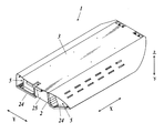
図1は、本実施形態における道路照明灯具1が後述のポール100に取り付けられた状態を示す図であり、図2は、道路照明灯具1の斜視図であり、図3は、カバー3を取り外した状態の道路照明灯具1の斜視図である。
図1は、本実施形態における道路照明灯具1が後述のポール100に取り付けられた状態を示す図であり、図2は、道路照明灯具1の斜視図であり、図3は、カバー3を取り外した状態の道路照明灯具1の斜視図である。
図1に示すように、道路照明灯具1は、例えば2灯式のポール100の上端部に設けられ、図示しない車両(自動車)が走行する道路を上方から照明するものである。
道路照明灯具1を支持するポール100は、上部が枝分かれしたY字状に形成されて、その枝分かれ部分である2つのブーム110が斜め上方に向かってそれぞれ傾斜しており、当該2つのブーム110の各先端部に道路照明灯具1が下方向きに取り付けられる。
なお、道路照明灯具1はブーム110に沿って傾斜した状態に配置されるものであるが、以下では、説明の簡単のために略水平に配置されているものとする。
道路照明灯具1を支持するポール100は、上部が枝分かれしたY字状に形成されて、その枝分かれ部分である2つのブーム110が斜め上方に向かってそれぞれ傾斜しており、当該2つのブーム110の各先端部に道路照明灯具1が下方向きに取り付けられる。
なお、道路照明灯具1はブーム110に沿って傾斜した状態に配置されるものであるが、以下では、説明の簡単のために略水平に配置されているものとする。
具体的に、道路照明灯具1は、図2及び図3に示すように、やや長尺な扁平形状に形成されており、その長手方向Xが道路の幅員方向に略沿うとともに、当該長手方向Xと直交する幅方向Yが車両の進行方向に沿うように配置される。
この道路照明灯具1は、メインフレーム2及びカバー3を備えており、これらメインフレーム2とカバー3とで形成される灯室の内部に、2つの電源ユニット4,4と、2つの照明モジュール5,5とを収容している。
この道路照明灯具1は、メインフレーム2及びカバー3を備えており、これらメインフレーム2とカバー3とで形成される灯室の内部に、2つの電源ユニット4,4と、2つの照明モジュール5,5とを収容している。
メインフレーム2は、主に2つの電源ユニット4,4及び2つの照明モジュール5,5を支持する部品である。
このメインフレーム2は、当該メインフレーム2に必要な強度を保持する骨格部21を有している。骨格部21は、長手方向Xに沿ってメインフレーム2の略全長に亘って形成されており、その両端には、カバー3を取り付けるための立壁25がそれぞれ立設されている。
骨格部21のうち、長手方向Xの一端側(以下、「基端側」という。)は、ポール100のブーム110が固定されるポール固定部22となっている。ポール固定部22は、長手方向Xに沿ったV字状のポール受け溝221を有するとともに、その先端側の端部にポール突き当て部222を有している。ポール100のブーム110は、基端側の立壁25に形成された挿通孔25aに挿通されて、ポール受け溝221に嵌められつつ先端面をポール突き当て部222に突き当てた状態で、2つのU字ボルト61,61と図示しないナットとによってポール固定部22に締結固定されるようになっている。
一方、骨格部21のうち、ポール固定部22よりも長手方向Xの他端側(以下、「先端側」という。)の部分は、ポール固定部22よりもやや狭い幅に形成された主骨格部23となっている。この主骨格部23は、2つの電源ユニット4,4及び2つの照明モジュール5,5を支持する部分となっている。
このメインフレーム2は、当該メインフレーム2に必要な強度を保持する骨格部21を有している。骨格部21は、長手方向Xに沿ってメインフレーム2の略全長に亘って形成されており、その両端には、カバー3を取り付けるための立壁25がそれぞれ立設されている。
骨格部21のうち、長手方向Xの一端側(以下、「基端側」という。)は、ポール100のブーム110が固定されるポール固定部22となっている。ポール固定部22は、長手方向Xに沿ったV字状のポール受け溝221を有するとともに、その先端側の端部にポール突き当て部222を有している。ポール100のブーム110は、基端側の立壁25に形成された挿通孔25aに挿通されて、ポール受け溝221に嵌められつつ先端面をポール突き当て部222に突き当てた状態で、2つのU字ボルト61,61と図示しないナットとによってポール固定部22に締結固定されるようになっている。
一方、骨格部21のうち、ポール固定部22よりも長手方向Xの他端側(以下、「先端側」という。)の部分は、ポール固定部22よりもやや狭い幅に形成された主骨格部23となっている。この主骨格部23は、2つの電源ユニット4,4及び2つの照明モジュール5,5を支持する部分となっている。
メインフレーム2のうち、主骨格部23の幅方向Yの両側には、2つの照明モジュール5,5を支持する2つのモジュール支持部24,24が側方へ張り出すように設けられている。但し、2つのモジュール支持部24,24のうちの一方は、幅方向Yの先端に向かってやや上向きに傾斜した状態に設けられている。各モジュール支持部24は、図示は省略するが、支持する照明モジュール5の発光部(後述するレンズ板53)を下方へ露出させるように、当該発光部の周縁部のみを支持する枠状に形成されている。
カバー3は、道路照明灯具1の蓋部品であり、薄いアルミニウム板で形成されている。このカバー3は、長手方向Xの両端でメインフレーム2の2つの立壁25,25に取り付けられている。また、各立壁25よりも幅方向Yの両側の部分ではカバー3とメインフレーム2との間が開口しており、当該開口が2つの照明モジュール5,5を放熱させるための通風孔となっている。
2つの電源ユニット4,4は、複数のスペーサ41,…によって隙間を介在させた状態で上下方向に並設され、メインフレーム2の主骨格部23に固定されている。これら2つの電源ユニット4,4は、2つの照明モジュール5,5に対応しており、当該2つの照明モジュール5,5に個別に電力を供給するように電気的に接続されている。
2つの照明モジュール5,5は、道路照明灯具1の光源部であり、メインフレーム2の2つのモジュール支持部24,24に支持されている。
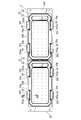
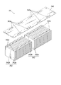
図4A及び図4Bは、照明モジュール5の平面図及び側面図であり、図5は、照明モジュール5のうち、後述する放熱ユニット54の分解斜視図である。
図4A及び図4Bに示すように、各照明モジュール5は、2つのLED(発光ダイオード)ユニット51,51と、放熱ユニット54とから構成されている。
図4A及び図4Bは、照明モジュール5の平面図及び側面図であり、図5は、照明モジュール5のうち、後述する放熱ユニット54の分解斜視図である。
図4A及び図4Bに示すように、各照明モジュール5は、2つのLED(発光ダイオード)ユニット51,51と、放熱ユニット54とから構成されている。
このうち、2つのLEDユニット51,51は、複数のLED520,…が実装されたLED基板52と、複数のLED520,…からの光を配光制御するためのレンズ板53とからそれぞれ構成されている。これらLED基板52とレンズ板53とは、互いに略同一のサイズに形成され、互いの四辺を合わせた状態で重ねられている。また、レンズ板53の幅方向の両端には、後述するクリップ55の第一係止部551aを係止する係止溝53aがその表面側に複数形成されている。
一方、放熱ユニット54は、図5に示すように、長尺な底板541の裏面に、複数のフィン板542,…が固定されて構成されている。
底板541は、アルミニウム平板で形成されており、本実施形態では、LED基板52からフィン板542への伝熱を促進させて放熱効果をより高めるために、薄い板厚(本実施形態では約1.2mm)のもので形成されている。この底板541の幅方向の両端には、後述するクリップ55の第二係止部552aを係止する係止孔541aが複数形成されている。この係止孔541aは、レンズ板53の係止溝53aとほぼ対応する位置に設けられている。
各フィン板542は、U字状に板金成形された薄いアルミニウム板であり、その開口側を底板541とは反対側に向けて当該底板541に固定されている。つまり、各フィン板542は、所定間隔の2枚のフィン542a,542aが、その間の連結部542bで連結された形状となっている。複数のフィン板542,…は、隣り合う2つのフィン542a,542aが上記所定間隔となるように、底板541の長手方向に沿って配列されている。但し、2つのLEDユニット51,51の間に位置する底板541の長手方向中央には、隣り合う2つのフィン板542,542間にやや広めの間隔が空いている。
これら底板541と各フィン板542とは、いわゆるダボカシメによって固定されている。具体的には、底板541と各フィン板542とは、フィン板542の連結部542bに形成された下穴542cに、底板541の裏面側に突出されたダボ(図示省略)を挿通させて、当該ダボの頭部を冶具で潰すことにより、当該フィン板542と底板541とがカシメ固定されている。こうして、底板541の裏面に複数のフィン542a,…が立設された状態となっている。
底板541は、アルミニウム平板で形成されており、本実施形態では、LED基板52からフィン板542への伝熱を促進させて放熱効果をより高めるために、薄い板厚(本実施形態では約1.2mm)のもので形成されている。この底板541の幅方向の両端には、後述するクリップ55の第二係止部552aを係止する係止孔541aが複数形成されている。この係止孔541aは、レンズ板53の係止溝53aとほぼ対応する位置に設けられている。
各フィン板542は、U字状に板金成形された薄いアルミニウム板であり、その開口側を底板541とは反対側に向けて当該底板541に固定されている。つまり、各フィン板542は、所定間隔の2枚のフィン542a,542aが、その間の連結部542bで連結された形状となっている。複数のフィン板542,…は、隣り合う2つのフィン542a,542aが上記所定間隔となるように、底板541の長手方向に沿って配列されている。但し、2つのLEDユニット51,51の間に位置する底板541の長手方向中央には、隣り合う2つのフィン板542,542間にやや広めの間隔が空いている。
これら底板541と各フィン板542とは、いわゆるダボカシメによって固定されている。具体的には、底板541と各フィン板542とは、フィン板542の連結部542bに形成された下穴542cに、底板541の裏面側に突出されたダボ(図示省略)を挿通させて、当該ダボの頭部を冶具で潰すことにより、当該フィン板542と底板541とがカシメ固定されている。こうして、底板541の裏面に複数のフィン542a,…が立設された状態となっている。
各LEDユニット51と放熱ユニット54とは、複数のクリップ55,…によって互いの周縁部が押圧固定されている。
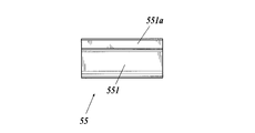
図6A,図6B及び図6Cは、クリップ55の上面図、側面図及び下面図であり、図7は、図4AのVII-VII線での断面図であって、クリップ55による固定状態を説明するための図である。
図6A,図6B及び図6Cに示すように、クリップ55は、板状の弾性材料が略U字状に成形されたものであり、その弾性力でLEDユニット51と放熱ユニット54とを挟むように押圧固定する。
図6A,図6B及び図6Cは、クリップ55の上面図、側面図及び下面図であり、図7は、図4AのVII-VII線での断面図であって、クリップ55による固定状態を説明するための図である。
図6A,図6B及び図6Cに示すように、クリップ55は、板状の弾性材料が略U字状に成形されたものであり、その弾性力でLEDユニット51と放熱ユニット54とを挟むように押圧固定する。
クリップ55のうち、LEDユニット51を押圧する第一押圧部551の先端には、この第一押圧部551よりも当該クリップ55の内側に突設された第一係止部551aが形成されている。
一方、クリップ55のうち、放熱ユニット54を押圧する第二押圧部552は、部分的に切欠くことで、複数(本実施形態では3つ)に分けられている。これら複数の第二押圧部552,…は、複数のフィン542a,…間に一つ置きに挿入可能なように、その幅及び間隔が所定のものに形成されている。また、第二押圧部552の先端には、この第二押圧部552よりも当該クリップ55の内側に突設された第二係止部552aが形成されている。
一方、クリップ55のうち、放熱ユニット54を押圧する第二押圧部552は、部分的に切欠くことで、複数(本実施形態では3つ)に分けられている。これら複数の第二押圧部552,…は、複数のフィン542a,…間に一つ置きに挿入可能なように、その幅及び間隔が所定のものに形成されている。また、第二押圧部552の先端には、この第二押圧部552よりも当該クリップ55の内側に突設された第二係止部552aが形成されている。
このクリップ55は、図7に示すように、底板541の表面にLED基板52を密着させるようにして、LEDユニット51と放熱ユニット54とを押圧固定する。より詳しくは、LEDユニット51のレンズ板53を第一押圧部551で押圧し、放熱ユニット54の底板541を第二押圧部552で押圧することにより、LED基板52を挟み込むようにして、これらレンズ板53、LED基板52及び底板541の3体を共締めする。またこのとき、第一押圧部551の第一係止部551aがレンズ板53の係止溝53aに係止され、第二押圧部552の第二係止部552aが底板541の係止孔541aに係止されることで、クリップ55の脱落が防止されるようになっている。
以上のように、本実施形態の道路照明灯具1によれば、複数のLED520,…が実装されたLED基板52と、複数のフィン542a,…が立設された底板541とが、互いの周縁部をクリップ55で押圧固定されている。これにより、基板と底板とがねじで締結固定されていた従来と異なり、放熱効果を高めるために底板541を薄くした場合であっても、当該底板541とLED基板52とを固定することができる。
したがって、フィン542aによる放熱効果を向上させつつ、LED基板52と底板541とを好適に固定することができる。
したがって、フィン542aによる放熱効果を向上させつつ、LED基板52と底板541とを好適に固定することができる。
また、クリップ55のうち、底板541の裏面を押圧する第二押圧部552が、当該裏面に立設された複数のフィン542a,…の間に挿入可能に形成されている。これにより、クリップ55の第二押圧部552を複数のフィン542a,…の間に挿入させた状態でLED基板52と底板541とを押圧固定できるので、フィン542aをクリップ55から逃がす必要なく底板541の幅一杯にまで広く形成することができる。
したがって、フィン542aによる放熱効果をさらに向上させつつ、LED基板52と底板541とを好適に固定することができる。
したがって、フィン542aによる放熱効果をさらに向上させつつ、LED基板52と底板541とを好適に固定することができる。
なお、本発明を適用可能な実施形態は、上述した実施形態に限定されることなく、本発明の趣旨を逸脱しない範囲で適宜変更可能である。
例えば、上記実施形態では、クリップ55の第二押圧部552が3つ設けられていることとしたが、この第二押圧部552は、同時に複数のフィン542a,…の間に挿入可能であればよく、その数量などは特に限定されない。
また、道路照明灯具1が2つの電源ユニット4及び照明モジュール5を備えることとしたが、これらの数量は特に限定されない。
また、道路照明灯具1がポール100に取り付けられることとしたが、本発明に係る道路照明灯具は、上方から道路を照明できるものであれば、ポール(支柱)に取り付けられるものに限定されず、例えばトンネル内の壁面や天井に固定されるものであってもよい。
以上のように、本発明に係る道路照明灯具は、フィンによる放熱効果を向上させつつ、基板とフィンの底板とを好適に固定するのに有用である。
1 道路照明灯具
2 メインフレーム
3 カバー
4 電源ユニット
5 照明モジュール
51 LEDユニット
52 LED基板
520 LED
53 レンズ板(レンズ部材)
53a 係止溝
54 放熱ユニット
541 底板
541a 係止孔
542 フィン板
542a フィン
542b 連結部
55 クリップ
551 第一押圧部
551a 第一係止部
552 第二押圧部
552a 第二係止部
2 メインフレーム
3 カバー
4 電源ユニット
5 照明モジュール
51 LEDユニット
52 LED基板
520 LED
53 レンズ板(レンズ部材)
53a 係止溝
54 放熱ユニット
541 底板
541a 係止孔
542 フィン板
542a フィン
542b 連結部
55 クリップ
551 第一押圧部
551a 第一係止部
552 第二押圧部
552a 第二係止部
Claims (3)
- LEDが実装されたLED基板と、一方の面に複数のフィンが立設されるとともに他方の面に前記LED基板が固定される底板とを備える道路照明灯具であって、
前記LED基板と前記底板とが、互いの周縁部をクリップで押圧固定されていることを特徴とする道路照明灯具。 - 前記クリップのうち、前記底板の前記一方の面を押圧する押圧部は、当該一方の面に立設された前記複数のフィンの間に挿入可能に形成されていることを特徴とする請求項1に記載の道路照明灯具。
- 前記LEDからの光を配光制御するためのレンズ部材を備え、
前記クリップは、前記レンズ部材、前記LED基板及び前記底板を共締めすることを特徴とする請求項1又は2に記載の道路照明灯具。
Applications Claiming Priority (2)
| Application Number | Priority Date | Filing Date | Title |
|---|---|---|---|
| JP2014-143264 | 2014-07-11 | ||
| JP2014143264A JP2016018767A (ja) | 2014-07-11 | 2014-07-11 | 道路照明灯具 |
Publications (1)
| Publication Number | Publication Date |
|---|---|
| WO2016006446A1 true WO2016006446A1 (ja) | 2016-01-14 |
Family
ID=55064084
Family Applications (1)
| Application Number | Title | Priority Date | Filing Date |
|---|---|---|---|
| PCT/JP2015/068189 Ceased WO2016006446A1 (ja) | 2014-07-11 | 2015-06-24 | 道路照明灯具 |
Country Status (2)
| Country | Link |
|---|---|
| JP (1) | JP2016018767A (ja) |
| WO (1) | WO2016006446A1 (ja) |
Cited By (1)
| Publication number | Priority date | Publication date | Assignee | Title |
|---|---|---|---|---|
| US11028314B2 (en) | 2018-07-13 | 2021-06-08 | Integrity Bio-Chemicals, Llc | Compositions comprising aminated dextrin compounds and subterranean treatment methods using the same |
Citations (6)
| Publication number | Priority date | Publication date | Assignee | Title |
|---|---|---|---|---|
| JP2006331817A (ja) * | 2005-05-25 | 2006-12-07 | Matsushita Electric Works Ltd | 発光装置及びそれを用いた照明器具 |
| JP2008198398A (ja) * | 2007-02-08 | 2008-08-28 | Sony Corp | バックライト装置及び表示装置 |
| JP2009099492A (ja) * | 2007-10-19 | 2009-05-07 | Koito Ind Ltd | 道路照明装置 |
| JP3164827U (ja) * | 2010-02-06 | 2010-12-16 | ビーアンドエム オプティクス カンパニー リミテッド | 落下防止機能付きのled照明装置 |
| JP3176794U (ja) * | 2011-06-03 | 2012-07-05 | 榮貴 林 | Ledライト装置 |
| JP2014007124A (ja) * | 2012-06-27 | 2014-01-16 | Panasonic Corp | Led照明器具及びこれを用いたled照明装置 |
-
2014
- 2014-07-11 JP JP2014143264A patent/JP2016018767A/ja active Pending
-
2015
- 2015-06-24 WO PCT/JP2015/068189 patent/WO2016006446A1/ja not_active Ceased
Patent Citations (6)
| Publication number | Priority date | Publication date | Assignee | Title |
|---|---|---|---|---|
| JP2006331817A (ja) * | 2005-05-25 | 2006-12-07 | Matsushita Electric Works Ltd | 発光装置及びそれを用いた照明器具 |
| JP2008198398A (ja) * | 2007-02-08 | 2008-08-28 | Sony Corp | バックライト装置及び表示装置 |
| JP2009099492A (ja) * | 2007-10-19 | 2009-05-07 | Koito Ind Ltd | 道路照明装置 |
| JP3164827U (ja) * | 2010-02-06 | 2010-12-16 | ビーアンドエム オプティクス カンパニー リミテッド | 落下防止機能付きのled照明装置 |
| JP3176794U (ja) * | 2011-06-03 | 2012-07-05 | 榮貴 林 | Ledライト装置 |
| JP2014007124A (ja) * | 2012-06-27 | 2014-01-16 | Panasonic Corp | Led照明器具及びこれを用いたled照明装置 |
Cited By (1)
| Publication number | Priority date | Publication date | Assignee | Title |
|---|---|---|---|---|
| US11028314B2 (en) | 2018-07-13 | 2021-06-08 | Integrity Bio-Chemicals, Llc | Compositions comprising aminated dextrin compounds and subterranean treatment methods using the same |
Also Published As
| Publication number | Publication date |
|---|---|
| JP2016018767A (ja) | 2016-02-01 |
Similar Documents
| Publication | Publication Date | Title |
|---|---|---|
| JP4879218B2 (ja) | レンズ体、光源ユニット及び照明装置 | |
| US7637638B2 (en) | Lighting apparatus | |
| TWI608190B (zh) | 具有促進熱傳導及流體密封的led照明設備 | |
| JP4496299B1 (ja) | レンズ体、光源ユニット及び照明装置 | |
| CN101614386A (zh) | 发光二极管灯具 | |
| US20090268477A1 (en) | Led lamp | |
| US9494730B1 (en) | Multiple waveguide edge lit structure | |
| KR20160114760A (ko) | 엘이디 조명용 렌즈구조체 | |
| JP2010073670A (ja) | Led照明器具 | |
| JP6586306B2 (ja) | Led照明器具 | |
| JP3163443U (ja) | Led式照明装置 | |
| US7824071B2 (en) | LED lamp including mounting plates with inclined portions | |
| US8944666B2 (en) | Lighting device | |
| KR101093182B1 (ko) | 가로등용 엘이디 조명등 | |
| JP2016018767A (ja) | 道路照明灯具 | |
| JP5861092B2 (ja) | 照明器具 | |
| JP6315757B2 (ja) | 照明器具 | |
| JP2015021645A (ja) | 天井パネル | |
| JP5853147B2 (ja) | 照明器具 | |
| KR101623708B1 (ko) | 엘이디 조명구조체 | |
| JP2014232586A (ja) | 発光素子用の基板及びこれを用いた照明装置 | |
| JP6399448B2 (ja) | 光源ユニット及び照明器具 | |
| KR20120049070A (ko) | Led 조명 장치의 체결 구조 | |
| US8322891B2 (en) | LED light source assembly with heat sink and heat conductive glass cover | |
| JP7098941B2 (ja) | Led照明灯 |
Legal Events
| Date | Code | Title | Description |
|---|---|---|---|
| 121 | Ep: the epo has been informed by wipo that ep was designated in this application |
Ref document number: 15819158 Country of ref document: EP Kind code of ref document: A1 |
|
| NENP | Non-entry into the national phase |
Ref country code: DE |
|
| 122 | Ep: pct application non-entry in european phase |
Ref document number: 15819158 Country of ref document: EP Kind code of ref document: A1 |