WO2016006400A1 - 入力装置および電子機器 - Google Patents
入力装置および電子機器 Download PDFInfo
- Publication number
- WO2016006400A1 WO2016006400A1 PCT/JP2015/067427 JP2015067427W WO2016006400A1 WO 2016006400 A1 WO2016006400 A1 WO 2016006400A1 JP 2015067427 W JP2015067427 W JP 2015067427W WO 2016006400 A1 WO2016006400 A1 WO 2016006400A1
- Authority
- WO
- WIPO (PCT)
- Prior art keywords
- vibration sensor
- finger
- output
- user
- input device
- Prior art date
- Legal status (The legal status is an assumption and is not a legal conclusion. Google has not performed a legal analysis and makes no representation as to the accuracy of the status listed.)
- Ceased
Links
Images










Classifications
-
- G—PHYSICS
- G06—COMPUTING OR CALCULATING; COUNTING
- G06F—ELECTRIC DIGITAL DATA PROCESSING
- G06F3/00—Input arrangements for transferring data to be processed into a form capable of being handled by the computer; Output arrangements for transferring data from processing unit to output unit, e.g. interface arrangements
- G06F3/01—Input arrangements or combined input and output arrangements for interaction between user and computer
Definitions
- the present invention relates to an input device and an electronic device, and more particularly to an input device and an electronic device that accept an input operation with a user's finger.
- a touch panel is known as an input device that accepts an input operation by a user's finger in an electronic device.
- Patent Document 1 Japanese Patent No. 4610416 describes a capacitive touch panel.
- Patent Document 2 describes an electronic device including an acceleration sensor for detecting a touch impact level in addition to a touch panel.
- Japanese Patent No. 4610416 Japanese Patent No. 5204286
- the degree of touch impact can be detected by an acceleration sensor, but after touch impact, the touch panel is used to determine whether or not the display is touched like a finger. It is. Therefore, only the acceleration sensor cannot accept a screen scroll operation by the user.
- an object of the present invention is to provide an input device that can accept a scroll operation by a user and that is not easily soiled by the touch of a user's finger, and an electronic apparatus including such an input device.
- the present invention provides an input device mounted on an electronic device, and includes an input member having a plurality of protrusions provided along a straight line or a curve, and a plurality of protrusions. Based on the output of at least one vibration sensor that is generated when the user's finger comes into contact and is transmitted through a member of the electronic device, and the output of the at least one vibration sensor, the user's finger is aligned or curved. And a signal processing circuit for determining whether the user's finger has been swept in a second direction opposite to the first direction on a straight line or a curve.
- the input device includes a first vibration sensor and a second vibration sensor as at least one vibration sensor.
- the phase of the output of the first vibration sensor is opposite to the phase of the output of the second vibration sensor.
- the signal processing circuit determines that the user's finger has been swept in the first direction when the output of the first vibration sensor first rises and the output of the second vibration sensor first falls, and the first When the output of the first vibration sensor falls first and the output of the second vibration sensor first rises, it is determined that the user's finger has been swept in the second direction.
- the input device includes a first vibration sensor and a second vibration sensor as at least one vibration sensor.
- the distance between the first vibration sensor and one end on the straight line or the curve is shorter than the distance between the second vibration sensor and one end, and the distance between the first vibration sensor and the other end on the straight line or the curve is
- the first vibration sensor and the second vibration sensor are disposed at a position that is longer than the distance between the second vibration sensor and the other end.
- the signal processing circuit is configured such that the user's finger moves in the first direction based on a temporal change in the relationship between the peak time of the output of the first vibration sensor and the peak time of the output of the second vibration sensor. It is determined whether it has been swept or swept in the second direction.
- the signal processing circuit has a sweep speed of the user's finger based on a time interval between a plurality of peaks of the output of the first vibration sensor or a time interval between a plurality of peaks of the output of the second vibration sensor. Is calculated.
- the input device includes one vibration sensor as at least one vibration sensor.
- the distance between the protrusion and the vibration sensor increases or decreases in accordance with the order of arrangement of the plurality of protrusions.
- the signal processing circuit determines whether the user's finger has been swept in the first direction or in the second direction based on whether the amplitude of the peak of the output of the vibration sensor increases or decreases. To do.
- the input device includes one vibration sensor as at least one vibration sensor.
- the protrusion is formed in a staircase shape in which the side near one end on a straight line or a curve is high and the side near the other end on the straight line or the curve is low, and the direction from one end to the other end is the first direction. .
- the signal processing circuit determines that the user's finger has been swept in the second direction when there is one whose peak time interval of the output of the vibration sensor is within a predetermined time.
- the input device includes one vibration sensor as at least one vibration sensor.
- the interval between the edges near the one end on the straight line or the curve in the plurality of protrusions is different from the interval between the edges near the other end on the straight line or the curve in the plurality of protrusions.
- the signal processing circuit calculates the sweep speed of the user's finger based on a time interval between a plurality of peaks of the output of the vibration sensor.
- the present invention is an input device mounted on an electronic apparatus, and includes an input member having a plurality of protrusions provided along a straight line or a curved line, and a user's finger contacting the plurality of protrusions. At least one vibration sensor that detects vibrations that are generated and transmitted through a member of the electronic device, and a signal processing circuit that calculates a sweep speed of the user's finger based on the output of the at least one vibration sensor.
- the input device includes a first vibration sensor and a second vibration sensor as at least one vibration sensor.
- the signal processing circuit calculates the sweep speed of the user's finger based on the time interval between the plurality of peaks of the output of the first vibration sensor or the time interval between the plurality of peaks of the output of the second vibration sensor. .
- the input device includes one vibration sensor as at least one vibration sensor.
- the signal processing circuit calculates the sweep speed of the user's finger based on the time interval between the peaks of the vibration sensor output.
- the present invention is an electronic apparatus including the above-described input device, and the plurality of protrusions of the input member are not arranged on the surface of the display unit included in the electronic apparatus.
- the input device of the present invention can accept a scroll operation by the user and is not soiled by the touch of the user's finger.
- FIG. 1 It is a figure showing the structure of the input device of 1st Embodiment. It is a figure showing the external appearance of the member for input. It is a figure showing a board
- (A) is the figure which looked at the projection part of a 1st embodiment from the Z direction.
- (B) is the figure which looked at the projection part of a 1st embodiment from the Y direction.
- A) is a figure showing a load.
- (B) is a simulation result of the transient response of the displacement amount in the Z-axis direction of the first vibration sensor and the second vibration sensor when the load shown in (a) is applied in the ⁇ X direction of the side surface of the substrate.
- (A) is a figure showing the output voltage of a 1st vibration sensor and the output voltage of a 2nd vibration sensor when a finger
- (B) is a diagram showing the output voltage of the first vibration sensor and the output voltage of the second vibration sensor when the finger is swept from the bottom to the top (in the ⁇ X direction) with respect to the protrusion. is there. It is a flowchart showing the procedure of determination of the sweep direction of a user's finger
- FIG. (A) is the peak time of the output voltage of the first vibration sensor and the peak of the output voltage of the second vibration sensor when the finger is swept from the top to the bottom (in the X direction) with respect to the protrusion.
- FIG. (B) shows the peak time of the output voltage of the first vibration sensor and the output voltage of the second vibration sensor when the finger is swept from the bottom to the top (in the ⁇ X direction) with respect to the protrusion. It is a figure showing a peak time typically. It is a flowchart showing the procedure of determination of the sweep direction of a user's finger
- (A) is a figure which represents typically the amplitude of the peak of the output voltage of a 1st vibration sensor when a finger
- (b) is a diagram schematically showing the amplitude of the peak of the output voltage of the first vibration sensor when the finger is swept from the bottom to the top (in the ⁇ X direction) with respect to the protrusion. It is a flowchart showing the procedure of determination of the sweep direction of a user's finger
- (A) is a figure showing typically the amplitude of the peak of the output voltage of the 2nd vibration sensor when a finger is swept from the upper part to the lower part (X direction) to the projection part.
- (B) is a diagram schematically showing the amplitude of the peak of the output voltage of the second vibration sensor when the finger is swept from the bottom to the top (in the ⁇ X direction) with respect to the protrusion. It is a figure showing the projection part of 4th Embodiment.
- (A) is a figure which represents typically the amplitude of the peak of the output voltage of a 1st vibration sensor when a finger
- (B) is a diagram schematically showing the amplitude of the peak of the output voltage of the first vibration sensor when the finger is swept from the bottom to the top (in the ⁇ X direction) with respect to the protrusion. It is a flowchart showing the procedure of determination of the sweep direction of a user's finger
- (A) is the figure which looked at the projection part of a 5th embodiment from the Z direction.
- (B) is the figure which looked at the projection part of 5th Embodiment from the Y direction.
- (A) is a figure which represents typically the amplitude of the peak of the output voltage of a 1st vibration sensor when a finger
- (B) is a diagram schematically showing the amplitude of the peak of the output voltage of the first vibration sensor when the finger is swept from the bottom to the top (in the ⁇ X direction) with respect to the protrusion. It is a flowchart showing the procedure of determination of the sweep direction of a user's finger
- (A) is the figure which looked at the projection part of the modification of 5th Embodiment from the Z direction.
- (B) is the figure which looked at the projection part of the modification of 5th Embodiment from the Y direction.
- FIG. 1 is a diagram illustrating the configuration of the input device according to the first embodiment.
- the input device 1 includes an input member 2 and a substrate 3.
- a first vibration sensor 4, a second vibration sensor 5, and a signal processing circuit 6 are mounted on the substrate 3.
- the signal processing circuit 6 includes a sweep direction determination circuit 7 and a sweep speed calculation circuit 8.
- the first vibration sensor 4 and the second vibration sensor 5 are composed of acceleration sensors, and detect vibrations at the arranged positions.
- the sweep direction determination circuit 7 determines the sweep direction of the user's finger with respect to the protrusion 9.
- the sweep speed calculation circuit 8 calculates the sweep speed of the user's finger with respect to the protrusion 9.
- FIG. 2 is a diagram showing the appearance of the input member 2.
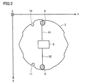
- FIG. 3 is a diagram showing the substrate 3.
- FIG. 4 is a diagram illustrating an appearance of an electronic device in which the input device 1 is mounted. 3 and 4 show the X axis, the Y axis, and the Z axis.
- the position where the coordinate value in the X-axis direction is large is referred to as the lower side
- the position where the coordinate value in the X-axis direction is small is referred to as the upper side.
- the input member 2 includes a protruding portion 9 including a plurality of protruding portions 9-1 to 9-N.
- the first vibration sensor 4 is disposed on the substrate 3 at a special position on the upper side of the watch-type electronic device.
- the second vibration sensor 5 is disposed on the substrate 3 at a special position below the watch-type electronic device.
- the first vibration sensor 4 and the second vibration sensor 5 detect vibration in the Z-axis direction.
- the protrusion 9 included in the input member 2 is not arranged on the surface of the display 51 (display unit) of the electronic device.
- the first vibration sensor 4 and the signal processing circuit 6 are connected by a wiring 61.
- the second vibration sensor 5 and the signal processing circuit 6 are connected by a wiring 62.
- the substrate 3 is attached to a member of an electronic device by passing a pin (not shown) through the pin holes 10 and 11.
- the input member 2 is attached to an electronic device.
- the vibration of the protrusions 9-1 to 9-N is transmitted to the substrate 3 through the members constituting the electronic device, and the first vibration sensor 4 and the second vibration are transmitted.
- the sensor 5 detects the vibration at the arranged position.
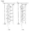
- FIG. 5A is a diagram of the protrusion 9 according to the first embodiment viewed from the Z direction.
- FIG. 5B is a diagram of the protrusion 9 according to the first embodiment viewed from the Y direction.
- Each protrusion 9-i is, for example, a rectangular parallelepiped whose length in the X direction and the Z direction is w and whose length in the Y direction is u.
- the protrusions 9-1 to 9-N are arranged on a straight line L.
- a protrusion 9-1 is disposed closer to one end point EN1 of the straight line L, and a protrusion 9-N is disposed closer to the other end point EN2 of the straight line L.
- the end point EN1 is at a position where the coordinate value in the X-axis direction is small (upper side), and the end point EN2 is at a position where the coordinate value in the X-axis direction is large (lower side).
- the interval between adjacent protrusions is D.
- the plurality of protrusions may be arranged on a straight line as in the present embodiment, or may be arranged on a curve.
- the protrusion 9-1 is arranged closer to one end point EN1 on the curve, and the protrusion 9-N is arranged closer to the other end point EN2 on the curve. Is done. Also in this case, the end point EN1 is at a position where the coordinate value in the X-axis direction is small (upper side), and the end point EN2 is at a position where the coordinate value in the X-axis direction is large (lower side).
- FIG. 6A shows a load.
- FIG. 6B shows the displacement of the first vibration sensor 4 and the second vibration sensor 5 in the Z-axis direction when the load shown in FIG. 6A is applied in the ⁇ X direction of the side surface of the substrate 3. It is a figure showing the simulation result of the quantity transient response.
- the displacement vibration of the first vibration sensor 4 and the displacement vibration of the second vibration sensor 5 in the Z-axis direction are in opposite phases.
- the first vibration sensor 4 and the second vibration sensor 5 are shifted, the above displacements are not in opposite phases. That is, in the present embodiment, the first vibration sensor 4 and the second vibration sensor 4 are in special positions such that the output of the first vibration sensor 4 and the output of the second second vibration sensor 5 are out of phase with each other.
- the vibration sensor 5 is arranged.
- the first vibration sensor 4 and the second vibration are positioned so that the vibration of the displacement of the first vibration sensor 4 in the Z-axis direction and the vibration of the displacement of the second vibration sensor 5 in the Z-axis direction are in phase.
- the sensor 5 is arranged, and the first vibration sensor 4 and the second vibration sensor 5 are electrically connected so that the output of the first vibration sensor 4 and the output of the second vibration sensor 5 are in opposite phases. It may be connected.
- FIG. 7A illustrates the output voltage of the first vibration sensor 4 and the output voltage of the second vibration sensor 5 when the finger is swept from the top to the bottom (in the X direction) with respect to the protrusion 9.
- FIG. FIG. 7A shows a result in a period in which the user's finger is in contact with the three protrusions.
- the first peak P1 of the output of the first vibration sensor 4 has a positive value and the first peak P2 of the output of the second vibration sensor 5 has a negative value, first, the first vibration sensor 4 It can be determined that the output rises and the output of the second vibration sensor 5 falls.
- FIG. 7B shows the output voltage of the first vibration sensor 4 and the output voltage of the second vibration sensor 5 when the finger is swept from the bottom to the top (in the ⁇ X direction) with respect to the protrusion 9.
- FIG. 7B shows a result in a period in which the user's finger is in contact with the three protrusions, as in FIG. 7A.
- the first peak P1 of the output of the first vibration sensor 4 is a negative value and the first peak P2 of the output of the second vibration sensor 5 is a positive value, first, the first vibration sensor 4 It can be determined that the output has fallen and the output of the second vibration sensor 5 has risen.
- the above-described rising / falling relationship is merely an example, and rising / falling may be reversed depending on how the substrate 3 is fixed. That is, when the finger is swept from the top to the bottom (in the X direction) with respect to the protrusion 9, the output of the first vibration sensor 4 first falls and the output of the second vibration sensor 5 When the finger rises and sweeps the finger from the bottom to the top (in the ⁇ X direction), the output of the first vibration sensor 4 first falls and the output of the second vibration sensor 5 May stand up.
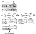
- FIG. 8 is a flowchart showing a procedure for determining the sweep direction of the user's finger with respect to the protrusion 9 and calculating the sweep speed according to the first embodiment.
- step S101 the sweep direction determination circuit 7 detects a peak at which the amplitude (absolute value) of the output of the first vibration sensor 4 first becomes a predetermined value or more at regular intervals, and detects the detected peak value V1 and The peak time t1 is acquired.
- step S102 the sweep direction determination circuit 7 detects a peak at which the amplitude (absolute value) of the output of the second vibration sensor 5 first becomes a predetermined value or more at regular intervals, and detects the detected peak value V2 and The peak time t2 is acquired.
- step S103 when V1> 0 and V2 ⁇ 0, the sweep direction determination circuit 7 advances the process to step S104.
- step S104 the sweep direction determination circuit 7 determines that the output of the first vibration sensor 4 rises and the output of the second vibration sensor 5 falls, and based on the determination, the user's finger is a protrusion. 9 is determined to have been swept in the X direction while in contact with 9.
- step S105 when V1 ⁇ 0 and V2> 0, the sweep direction determination circuit 7 advances the process to step S106.
- step S106 the sweep direction determination circuit 7 determines that the output of the first vibration sensor 4 falls and the output of the second vibration sensor 5 rises, and based on the determination, the user's finger is a protrusion. It is determined that the signal was swept in the ⁇ X direction while touching 9.
- step S107 the sweep speed calculation circuit 8 calculates an average value of time intervals between times t1 of a plurality of peaks of the output of the first vibration sensor 4.
- the sweep speed calculation circuit 8 calculates the sweep speed of the user's finger by dividing the calculated average value by the interval D between adjacent protrusions.
- the user's finger is swept from the top to the bottom or swept from the bottom to the top using the difference in phase between the outputs of the two vibration sensors. Can be determined. Thereby, the scroll operation by the user can be received. Also, unlike a member such as a touch panel, the protrusion is not easily soiled by the touch of the user's finger and cannot be attached to the surface of the display unit of the electronic device like the touch panel, so that the screen of the display unit is difficult to see due to the dirt. Nor.
- the date and time change direction of the clock-type electronic device can be switched (scroll processing is possible).
- the date and time change speed of the clock-type electronic device can be switched according to the calculated sweep speed of the user's finger.
- the sweep direction determination circuit 7 calculates an average value of time intervals between times t2 of a plurality of peaks of the output of the second vibration sensor 5, and divides the calculated average value by an interval D between adjacent protrusions. Thus, the sweep speed of the user's finger may be calculated.
- the input device 1 also includes first and second vibration sensors.
- the sweep direction of the user's finger is detected based on a change in the peak amplitude of the output of the first vibration sensor 4.
- the first vibration sensor 4 is disposed closest to the protrusion 9-1 among the protrusions 9-1 to 9-N.
- the second vibration sensor 5 is disposed closest to the protrusion 9-N among the protrusions 9-1 to 9-N.
- the sweep direction of the user's finger is detected based on the change in the relationship between the peak times of the outputs of the first vibration sensor 4 and the second vibration sensor 5.
- FIG. 9A shows the peak time of the output voltage of the first vibration sensor 4 and the second vibration sensor 5 when the finger is swept from the top to the bottom (in the X direction) with respect to the protrusion 9. It is a figure showing typically the time of the peak of the output voltage.
- the peak time of the output voltage of the first vibration sensor 4 is earlier than the peak time of the output voltage of the second vibration sensor 5, and the time difference gradually decreases.
- the time of the peak of the output voltage of the second vibration sensor 5 becomes earlier than the time of the peak of the output voltage of the first vibration sensor 4, and the time difference gradually increases. This is because the protrusion 9-1 is closer to the first vibration sensor 4 than the second vibration sensor 5, and the protrusion 9-N is closer to the second vibration sensor 5 than the first vibration sensor 4. is there.
- FIG. 9B shows the peak time of the output voltage of the first vibration sensor 4 and the second vibration sensor when the finger is swept from the bottom to the top (in the ⁇ X direction) with respect to the protrusion 9.
- 5 is a diagram schematically showing a peak time of an output voltage of 5.
- the peak time of the output voltage of the second vibration sensor 5 is earlier than the peak time of the output voltage of the first vibration sensor 4, and the time difference gradually decreases.
- the time of the peak of the output voltage of the first vibration sensor 4 becomes earlier than the time of the peak of the output voltage of the second vibration sensor 5, and the time difference gradually increases. This is because the protrusion 9-1 is closer to the first vibration sensor 4 than the second vibration sensor 5, and the protrusion 9-N is closer to the second vibration sensor 5 than the first vibration sensor 4. is there.
- the sweep direction of the user's finger is determined by using the above feature.
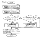
- FIG. 10 is a flowchart showing a procedure for determining the sweep direction of the user's finger with respect to the protrusion 9 and calculating the sweep speed according to the second embodiment.
- step S201 the sweep direction determination circuit 7 detects a peak at which the amplitude of the output of the first vibration sensor 4 is equal to or greater than a predetermined value, and the detected peak times t1 (1), t1 (2), t1 (3 ) ...
- step S202 the sweep direction determination circuit 7 detects a peak at which the amplitude of the output of the second vibration sensor 5 is equal to or greater than a predetermined value, and the detected peak times t2 (1), t2 (2), t2 (3 ) ...
- step S203 the sweep direction determination circuit 7 sets t1 (i) ⁇ t2 (i) when i ⁇ M for a certain M, and t1 (i)> t2 (i) when i> M. If is established, the process proceeds to step S204. That is, when i is small, the peak time of the output of the first vibration sensor 4 is earlier than the peak time of the output of the second vibration sensor 5, and when i is large, the output of the first vibration sensor 4 is When the peak time becomes later than the peak time of the output of the second vibration sensor 5, the process proceeds to step S204.
- step S204 the sweep direction determination circuit 7 determines that the user's finger has been swept in the X direction while contacting the protrusion 9.
- step S205 the sweep direction determination circuit 7 sets t1 (i)> t2 (i) when i ⁇ M for a certain M, and t1 (i) ⁇ t2 (i) when i> M. If is established, the process proceeds to step S206. That is, when i is small, the peak time of the output of the first vibration sensor 4 is later than the peak time of the output of the second vibration sensor 5, and when i is large, the output of the first vibration sensor 4 is When the peak time becomes earlier than the peak time of the output of the second vibration sensor 5, the process proceeds to step S206.
- step S206 the sweep direction determination circuit 7 determines that the user's finger has been swept in the ⁇ X direction while contacting the protrusion 9.
- step S207 the sweep speed calculation circuit 8 calculates the average value of the time intervals between times t1 (1), t1 (2), t1 (3)... Of the plurality of peaks of the output of the first vibration sensor 4. Is calculated.
- the sweep speed calculation circuit 8 calculates the sweep speed of the user's finger by dividing the calculated average value by the interval D between adjacent protrusions.
- the user's finger is swept from the top to the bottom or swept from the bottom to the top with respect to the protrusion using the front and rear relationship between the outputs of the two vibration sensors. Can be determined.
- the sweep direction determination circuit 7 calculates an average value of time intervals between times t2 (1), t2 (2), t2 (3)... Of a plurality of peaks of the output of the second vibration sensor 5.
- the sweep speed of the user's finger is calculated by dividing the calculated average value by the interval D between adjacent protrusions.
- the input device 1 of the present embodiment does not include the first and second vibration sensors but includes only the first vibration sensor 4.
- the sweep direction of the user's finger is detected based on a change in the peak amplitude of the output of the first vibration sensor 4.
- the first vibration sensor 4 is disposed closest to the protrusion 9-1 among the protrusions 9-1 to 9-N, and the distance between the protrusions 9-1, 9-2,. Becomes larger.
- FIG. 11A schematically shows the amplitude of the peak of the output voltage of the first vibration sensor 4 when the finger is swept from the top to the bottom (in the X direction) with respect to the protrusion 9. is there.
- the peak amplitude of the output voltage of the first vibration sensor 4 decreases with time.
- FIG. 11B schematically shows the amplitude of the peak of the output voltage of the first vibration sensor 4 when the finger is swept from the bottom to the top (in the ⁇ X direction) with respect to the protrusion 9. It is.
- the amplitude of the peak of the output voltage of the first vibration sensor 4 increases with time.
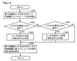
- FIG. 12 is a flowchart showing a procedure for determining the sweep direction of the user's finger with respect to the protrusion 9 and calculating the sweep speed according to the third embodiment.
- step S301 the sweep direction determination circuit 7 detects a peak at which the amplitude of the output of the first vibration sensor 4 is equal to or greater than a predetermined value, and the detected peak values V (1), V (2), V1 (3 ... And peak times t1 (1), t1 (2), t1 (3).
- step S302 the sweep direction determination circuit 7 advances the process to step S303 when V (i) decreases as i increases.
- step S303 the sweep direction determination circuit 7 determines that the user's finger has been swept in the X direction while contacting the protrusion 9.
- step S304 when V (i) increases as i increases, the sweep direction determination circuit 7 advances the process to step S305.
- step S305 the sweep direction determination circuit 7 determines that the user's finger has been swept in the ⁇ X direction while contacting the protrusion 9.
- step S306 the sweep speed calculation circuit 8 calculates the average value of the time intervals between times t1 (1), t1 (2), t1 (3)... Of the plurality of peaks of the output of the first vibration sensor 4. Is calculated.
- the sweep speed calculation circuit 8 calculates the sweep speed of the user's finger by dividing the calculated average value by the interval D between adjacent protrusions.
- the user's finger is swept from the top to the bottom with respect to the protrusion using the time change of the amplitude of the output of one vibration sensor, or from the bottom to the top. It can be determined whether it has been swept.
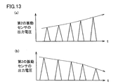
- FIG. 13A schematically shows the peak amplitude of the output voltage of the second vibration sensor 5 when the finger is swept from the top to the bottom (in the X direction) with respect to the protrusion 9. is there.
- the peak amplitude of the output voltage of the second vibration sensor 5 increases with time.
- FIG. 13B schematically shows the amplitude of the peak of the output voltage of the second vibration sensor 5 when the finger is swept from the bottom to the top (in the ⁇ X direction) with respect to the protrusion 9. It is.
- the peak amplitude of the output voltage of the second vibration sensor 5 decreases with time.
- the sweep direction determination circuit 7 allows the user's finger to move the protrusion 9 when the peak value V (i) of the output of the second vibration sensor 5 decreases as i increases. It is determined that it has been swept in the ⁇ X direction while being in contact with it, and if it increases as i increases, it is determined that the user's finger has been swept in the X direction while being in contact with the protrusion 9.
- the sweep direction determination circuit 7 calculates an average value of time intervals between times t2 (1), t2 (2), t2 (3)... Of the plurality of peaks of the output of the second vibration sensor 5. Then, the sweep speed of the user's finger is calculated by dividing the calculated average value by the interval D between the adjacent protrusions.
- the position of the first vibration sensor 4 may be anywhere as long as the peak amplitude increases or decreases due to the sweep of the user's finger. Therefore, the first vibration sensor 4 is arranged at a position other than a position (for example, a central position on the substrate) where the amplitude of the peak increases for a certain period and decreases for another period by the sweep of the user's finger.
- the input device 1 does not include the first and second vibration sensors but includes only the first vibration sensor 4.
- the first vibration sensor 4 is arranged at the same position as in the first embodiment, but may be at an arbitrary position on the substrate 3.
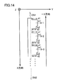
- FIG. 14 is a diagram of the protrusion 9 according to the fourth embodiment viewed from the Z direction.
- the protrusions 9-1 to 9-N are arranged on a straight line L.
- a protrusion 9-1 is disposed closer to one end point EN1 of the straight line L, and a protrusion 9-N is disposed closer to the other end point EN2 of the straight line L.
- the end point EN1 is at a position where the coordinate value in the X-axis direction is small (upper side), and the end point EN2 is at a position where the coordinate value in the X-axis direction is large (lower side).
- the protrusion 9-i is formed in a stepped shape that is high on the side close to the end point EN1 (height d1) and low on the side close to the end point EN2 (height d2). That is, the protrusion 9-i is composed of two rectangular parallelepipeds.
- the upper rectangular parallelepiped has, for example, a length d1 in the Y direction, a length u in the Z direction, and a length w1 in the X direction.
- the lower rectangular parallelepiped has a length in the Y direction of d2, a length in the Z direction of u, and a length in the X direction of w2.
- FIG. 15A is a diagram schematically showing the amplitude of the peak of the output voltage of the first vibration sensor 4 when the finger is swept from top to bottom (in the X direction) with respect to the protrusion 9. is there.
- the time intervals E1, E2, E3, and E3 of the peak of the output voltage of the first vibration sensor 4 all exceed a predetermined value TH1.
- FIG. 15B schematically shows the amplitude of the peak of the output voltage of the first vibration sensor 4 when the finger is swept from the bottom to the top (in the ⁇ X direction) with respect to the protrusion 9. It is.
- the time intervals F1, F3, F4, and F6 of the peak time of the output voltage of the first vibration sensor 4 exceed the predetermined value TH, but F2 and F5 are less than the predetermined value TH1.
- F2 and F5 are equal to or less than the predetermined value TH1 because the user's finger is swept upward from the bottom ( ⁇ X direction) and the user's finger is placed on the surface of the upper rectangular parallelepiped at the two protrusions. This is due to contact with two places on the surface of the lower rectangular parallelepiped.
- the user's finger moves from the bottom to the top ( ⁇ X direction). Can be determined to have been swept.
- FIG. 16 is a flowchart showing the procedure for determining the sweep direction of the user's finger with respect to the protrusion 9 and calculating the sweep speed according to the fourth embodiment.
- step S401 the sweep direction determination circuit 7 detects a peak where the amplitude of the output of the first vibration sensor 4 is equal to or greater than a predetermined value, and the detected peak times t1 (1), t1 (2), t1 (3 ) ...
- step S402 the sweep direction determination circuit 7 advances the process to step S403 when there is at least one of the adjacent peak time intervals that is equal to or less than the predetermined value TH1.
- step S403 the sweep direction determination circuit 7 determines that the user's finger has been swept in the ⁇ X direction while contacting the protrusion 9.
- step S404 the sweep direction determination circuit 7 determines that the user's finger has been swept in the X direction while contacting the protrusion 9. That is, when there is no time interval between adjacent peaks that is equal to or smaller than the predetermined value TH1, it is determined that the user's finger has been swept in the X direction.
- step S405 the sweep speed calculation circuit 8 calculates the average value of the time intervals between times t1 (1), t1 (2), t1 (3)... Of the plurality of peaks of the output of the first vibration sensor 4. Is calculated.
- the sweep speed calculation circuit 8 calculates the sweep speed of the user's finger by dividing the calculated average value by the interval D between adjacent protrusions.
- the protrusion is configured in a step shape, and the user's finger is moved from the top to the bottom with respect to the protrusion using the time interval of the peak of the output of one vibration sensor. It can be determined whether it has been swept or swept from bottom to top.
- This embodiment is different from the first embodiment in the width of the protrusions and the interval between the protrusions.
- the input device 1 includes only the first vibration sensor 4 instead of including the first and second vibration sensors.
- the first vibration sensor 4 is arranged at the same position as in the first embodiment, but may be at an arbitrary position on the substrate 3.
- FIG. 17A is a diagram of the protrusion 9 according to the fifth embodiment viewed from the Z direction.
- FIG. 17B is a diagram of the protrusion 9 according to the fifth embodiment viewed from the Y direction.
- the protrusions 9-1 to 9-N are arranged on a straight line L.
- a protrusion 9-1 is disposed closer to one end point EN1 of the straight line L, and a protrusion 9-N is disposed closer to the other end point EN2 of the straight line L.
- the end point EN1 is at a position where the coordinate value in the X-axis direction is small (upper side), and the end point EN2 is at a position where the coordinate value in the X-axis direction is large (lower side).
- the protrusion 9-i is a rectangular parallelepiped, for example, the length in the Z direction is w and the length in the Y direction is u.
- the length in the X direction of the protrusion 9-i and the interval between adjacent protrusions are not constant.
- the length of the projection 9-i in the X direction and the interval between adjacent projections are designed to satisfy the following conditions.
- the distance between the upper edge of a certain protrusion 9-i (side closer to the end point EN1) and the upper edge of the adjacent protrusion 9-i + 1 (side closer to the end point EN1) is a.
- the distance between the lower edge of the projection 9-i (side closer to the end point EN2) and the lower edge of the adjacent projection 9-i + 1 (side closer to the end point EN2) is b.
- a ⁇ b is a ⁇ b.
- FIG. 18A schematically shows the amplitude of the peak of the output voltage of the first vibration sensor 4 when the finger is swept from top to bottom (in the X direction) with respect to the protrusion 9. is there.
- the time intervals G1, G2, G3 of the peak of the output voltage of the first vibration sensor 4 are all equal to or less than a predetermined value TH2. This is because, when the finger is swept from the top to the bottom, the user's finger is likely to come into contact with the upper edge of the protrusion 9-i or the periphery of the upper edge. Because it is in contact with i.
- FIG. 18B schematically shows the amplitude of the peak of the output voltage of the first vibration sensor 4 when the finger is swept from the bottom to the top (in the ⁇ X direction) with respect to the protrusion 9. It is.
- the time intervals H1, H2, and H3 of the peak of the output voltage of the first vibration sensor 4 all exceed a predetermined value TH2. This is because when the finger is swept from the bottom to the top, the user's finger is likely to come into contact with the lower edge of the protrusion 9-i or around the lower edge. This is because they come into contact with the protrusions 9-i.
- the peak time interval changes not only with the sweep direction but also with the sweep speed.
- the sweep speed by the user's finger does not take an arbitrary value and normally falls within a predetermined range. Accordingly, by appropriately setting the distance a between the upper edges of the adjacent protrusions, the distance b between the lower edges of the adjacent protrusions, and the predetermined value TH2 for a predetermined range of sweep speed, The direction can be determined.
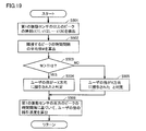
- FIG. 19 is a flowchart showing a procedure for determining the sweep direction of the user's finger with respect to the protrusion 9 and calculating the sweep speed according to the fifth embodiment.
- step S501 the sweep direction determination circuit 7 detects a peak at which the amplitude of the output of the first vibration sensor 4 is equal to or greater than a predetermined value, and the detected peak times t1 (1), t1 (2), t1 (3 ) ...
- step S502 the sweep direction determination circuit 7 calculates an average value M of time intervals of adjacent peaks from the detected peak times t1 (1), t1 (2), and t1 (3).
- step S503 when the average value M of the time intervals between adjacent peaks exceeds the predetermined value TH2, the sweep direction determination circuit 7 advances the process to step S504.
- step S504 the sweep direction determination circuit 7 determines that the user's finger has been swept in the ⁇ X direction while contacting the protrusion 9.
- step S505 the sweep direction determination circuit 7 determines that the user's finger has been swept in the X direction while contacting the protrusion 9. That is, when the average value M of the time intervals between adjacent peaks is equal to or less than the predetermined value TH2, it is determined that the user's finger has been swept in the X direction.
- step S506 the sweep speed calculation circuit 8 calculates the average value of the time intervals between times t1 (1), t1 (2), t1 (3)... Of the plurality of peaks of the output of the first vibration sensor 4. Is calculated.
- the sweep speed calculation circuit 8 calculates the sweep speed of the user's finger by dividing the calculated average value by the interval D between adjacent protrusions.
- the interval between the upper edges of the protrusions and the interval between the lower edges are made different, and the peak time interval of the output of one vibration sensor is used to Whether the user's finger has been swept from the top to the bottom or from the bottom to the top can be determined.
- FIG. 20 (a) is the figure which looked at the projection part 9 of the modification of 5th Embodiment from the Z direction.
- FIG. 20B is a diagram of the protrusion 9 according to the modification of the fifth embodiment viewed from the Y direction.
- the protrusions 9-1 to 9-N are arranged on a straight line L.
- a protrusion 9-1 is disposed closer to one end point EN1 of the straight line L, and a protrusion 9-N is disposed closer to the other end point EN2 of the straight line L.
- the end point EN1 is at a position where the coordinate value in the X-axis direction is small (upper side), and the end point EN2 is at a position where the coordinate value in the X-axis direction is large (lower side).
- the lower side of the protrusion 9-i (side closer to the end point EN2) is a plane.
- the upper side of the protrusion 9-i (side closer to the end point EN1) is a curved surface.
- the contact area between the user's finger and the protrusion is larger than when the user's finger is swept from the bottom to the top ( ⁇ X direction). Becomes larger.
- the sweep speed is not significantly different. The time interval of the peak of the output of the first vibration sensor becomes longer.
- the present invention is not limited to the above embodiment, and includes, for example, the following modifications.
- the input device of this embodiment can be incorporated not only in the electronic device on the watch side but also in an electronic device such as a smartphone or a smart watch.
Landscapes
- Engineering & Computer Science (AREA)
- General Engineering & Computer Science (AREA)
- Theoretical Computer Science (AREA)
- Human Computer Interaction (AREA)
- Physics & Mathematics (AREA)
- General Physics & Mathematics (AREA)
- User Interface Of Digital Computer (AREA)
Abstract
入力用部材(2)は、一直線上または曲線上に沿って設けられる複数の突起を有する。第1の振動センサ(4)および/または第2の振動センサ(5)は、複数の突起に対してユーザの指が接触したときに発生し、電子機器の部材を通じて伝わる振動を検知する。信号処理回路(6)は、第1の振動センサ(4)および/または第2の振動センサ(5)の出力に基づいて、ユーザの指が一直線上または曲線上の第1の方向に掃引されたか、またはユーザの指が一直線上または曲線上の第1の方向と逆の第2の方向に掃引されたかを判定する。
Description
本発明は、入力装置および電子機器に関し、特にユーザの指による入力操作を受け付ける入力装置および電子機器に関する。
従来から、電子機器における、ユーザの指による入力操作を受け付ける入力装置としてタッチパネルが知られている。
たとえば、特許第4610416号公報(特許文献1)には、静電容量型タッチパネルが記載されている。
また、特許第5204286号公報(特許文献2)には、タッチパネルに加えて、タッチ衝撃度を検出するための加速度センサを備える電子機器が記載されている。
しかしながら、特許文献1および特許文献2に記載のタッチパネルに対してユーザが指で入力動作を行うとタッチパネルが汚れるため、タッチパネル下のディスプレイの画面が見づらくなるという問題がある。
さらに、特許文献2に記載のタッチパネルでは、加速度センサによってタッチ衝撃度を検知することができるが、タッチ衝撃後は、ディスプレイを指で弾くようにタッチしたかどうかを判定するために使用されるものである。したがって、加速度センサのみでは、ユーザによる画面のスクロール操作などを受け付けることができない。
それゆえに、本発明の目的は、ユーザによるスクロール操作などを受け付けることができ、かつユーザの指の接触によって汚れにくい入力装置およびそのような入力装置を備える電子機器を提供することである。
上記課題を解決するために、本発明は、電子機器に搭載される入力装置であって、一直線上または曲線上に沿って設けられる複数の突起を有する入力用部材と、複数の突起に対してユーザの指が接触したときに発生し、電子機器の部材を通じて伝わる振動を検知する少なくとも1つの振動センサと、少なくとも1つの振動センサの出力に基づいて、ユーザの指が一直線上または曲線上の第1の方向に掃引されたか、またはユーザの指が一直線上または曲線上の第1の方向と逆の第2の方向に掃引されたかを判定する信号処理回路とを備える。
好ましくは、入力装置は、少なくとも1つの振動センサとして、第1の振動センサおよび第2の振動センサを含む。第1の振動センサの出力の位相と第2の振動センサの出力の位相とが逆相である。信号処理回路は、第1の振動センサの出力が最初に立ち上がり、かつ第2の振動センサの出力が最初に立ち下がる場合に、ユーザの指が第1の方向に掃引されたと判定し、第1の振動センサの出力が最初に立ち下がり、かつ第2の振動センサの出力が最初に立ち上がる場合に、ユーザの指が第2の方向に掃引されたと判定する。
好ましくは、入力装置は、少なくとも1つの振動センサとして、第1の振動センサおよび第2の振動センサを含む。第1の振動センサと一直線上または曲線上の一端との距離が、第2の振動センサと一端との距離よりも短く、第1の振動センサと一直線上または曲線上の他端との距離が、第2の振動センサと他端との距離よりも長くなるような位置に、第1の振動センサと第2の振動センサが配置される。信号処理回路は、第1の振動センサの出力のピークの時刻と第2の振動センサの出力のピークの時刻との間の先後関係の時間変化に基づいて、ユーザの指が第1の方向に掃引されたか、または第2の方向に掃引されたかを判定する。
好ましくは、信号処理回路は、第1の振動センサの出力の複数のピーク間の時間間隔、または第2の振動センサの出力の複数のピーク間の時間間隔に基づいて、ユーザの指の掃引速度を算出する。
好ましくは、入力装置は、少なくとも1つの振動センサとして、一つの振動センサを含む。複数の突起の並びの順番に従って、突起と振動センサとの距離が大きく、または小さくなる。信号処理回路は、振動センサの出力のピークの振幅が増加するか、または減少するかに基づいて、ユーザの指が第1の方向に掃引されたか、または第2の方向に掃引されたかを判定する。
好ましくは、入力装置は、少なくとも1つの振動センサとして、一つの振動センサを含む。突起は、一直線上または曲線上の一端に近い側は高く、一直線上または曲線上の他端に近い側は低くなる階段状に形成され、一端から他端への方向が第1の方向である。信号処理回路は、振動センサの出力のピークの時間間隔が所定時間以内となるものが存在する場合に、ユーザの指は第2の方向に掃引されたと判定する。
好ましくは、入力装置は、少なくとも1つの振動センサとして、一つの振動センサを含む。複数の突起における、一直線上または曲線上の一端に近い側のエッジ間の間隔と、複数の突起における、一直線上または曲線上の他端に近い側のエッジ間の間隔とが相違する。信号処理回路は、振動センサの出力の複数のピーク間の時間間隔が所定値以上か否かに基づいて、ユーザの指が第1の方向に掃引されたか、または第2の方向に掃引されたかを判定する。
好ましくは、信号処理回路は、振動センサの出力の複数のピーク間の時間間隔に基づいて、ユーザの指の掃引速度を算出する。
本発明は、電子機器に搭載される入力装置であって、一直線上または曲線上に沿って設けられる複数の突起を有する入力用部材と、複数の突起に対してユーザの指が接触したときに発生し、電子機器の部材を通じて伝わる振動を検知する少なくとも1つの振動センサと、少なくとも1つの振動センサの出力に基づいて、ユーザの指の掃引速度を算出する信号処理回路とを備える。
好ましくは、入力装置は、少なくとも1つの振動センサとして、第1の振動センサおよび第2の振動センサを含む。信号処理回路は、第1の振動センサの出力の複数のピーク間の時間間隔、または第2の振動センサの出力の複数のピーク間の時間間隔に基づいて、ユーザの指の掃引速度を算出する。
好ましくは、入力装置は、少なくとも1つの振動センサとして、一つの振動センサを含む。信号処理回路は、振動センサの出力の複数のピーク間の時間間隔に基づいて、ユーザの指の掃引速度を算出する。
本発明は、上述の入力装置を備えた電子機器であって、入力用部材の複数の突起は、電子機器に含まれる表示部の表面には配置されない。
本発明の入力装置は、ユーザによるスクロール操作を受け付けることができ、かつユーザの指の接触によって汚れない。
以下、本発明の実施の形態について図面を用いて説明する。
[第1の実施形態]
図1は、第1の実施形態の入力装置の構成を表わす図である。
[第1の実施形態]
図1は、第1の実施形態の入力装置の構成を表わす図である。
入力装置1は、入力用部材2と、基板3とを備える。基板3には、第1の振動センサ4と、第2の振動センサ5と、信号処理回路6とが搭載される。信号処理回路6は、掃引方向判定回路7と、掃引速度算出回路8とを備える。
第1の振動センサ4および第2の振動センサ5は、加速度センサで構成され、配置された位置の振動を検知する。
掃引方向判定回路7は、突起部9に対するユーザの指の掃引方向を判定する。
掃引速度算出回路8は、突起部9に対するユーザの指の掃引速度を算出する。
掃引速度算出回路8は、突起部9に対するユーザの指の掃引速度を算出する。
図2は、入力用部材2の外観を表わす図である。図3は、基板3を表わす図である。図4は、入力装置1が搭載される電子機器の外観を表わす図である。図3および図4には、X軸、Y軸、Z軸を示す。以下では、X軸方向の座標値が大きい位置を下側、X軸方向の座標値が小さい位置を上側と呼ぶことにする。
図2に示すように、入力用部材2は、複数の突起9-1~9-Nからなる突起部9を備える。
図3および図4に示すように、第1の振動センサ4は、基板3上であって、時計型の電子機器の上側の特別な位置に配置される。第2の振動センサ5は、基板3上であって、時計型の電子機器の下側の特別な位置に配置される。第1の振動センサ4および第2の振動センサ5は、Z軸方向の振動を検知する。入力用部材2に含まれる突起部9は、タッチパネルとは異なり、電子機器のディスプレイ51(表示部)の表面には、配置されない。
図3に示すように、第1の振動センサ4と信号処理回路6とは配線61で接続される。第2の振動センサ5と信号処理回路6とは配線62で接続される。
図3に示すように、基板3は、図示しないピンをピン穴10、11に通すことによって、電子機器の部材に取り付けられる。
入力用部材2は、電子機器に装着される。ユーザが入力用部材2の突起部9に触れることによって、突起9-1~9-Nの振動が電子機器を構成する部材を経て基板3に伝わり、第1の振動センサ4および第2の振動センサ5が、配置された位置の振動を検知する。
図5(a)は、第1の実施形態の突起部9をZ方向から見た図である。図5(b)は、第1の実施形態の突起部9をY方向から見た図である。
突起9-1~9-Nは、すべて同一の形状である。各突起9-iは、たとえば、X方向およびZ方向の長さがwで、Y方向の長さがuである直方体である。
突起9-1~9-Nは、一直線L上に配置される。一直線Lの一方の端点EN1に近い方に突起9-1が配置され、一直線Lの他方の端点EN2に近い方に突起9-Nが配置される。端点EN1は、X軸方向の座標値が小さい位置(上側)にあり、端点EN2は、X軸方向の座標値が大きい位置(下側)にある。隣接する突起間の間隔は、Dである。なお、複数の突起は、本実施形態のように一直線上に配置されていてもよいし、曲線上に配置されていてもよい。複数の突起が、曲線上に配置される場合でも、曲線上の一方の端点EN1に近い方に突起9-1が配置され、曲線上の他方の端点EN2に近い方に突起9-Nが配置される。この場合も、端点EN1は、X軸方向の座標値が小さい位置(上側)にあり、端点EN2は、X軸方向の座標値が大きい位置(下側)にある。
次に、第1の振動センサ4が置かれた特別な位置および第2の振動センサ5が置かれた特別な位置において、基板3に加えられた荷重がどのように伝わるかについて説明する。
図6(a)は、荷重を表わす図である。図6(b)は、図6(a)に示す荷重が基板3の側面の-X方向に与えられたときの、第1の振動センサ4および第2の振動センサ5のZ軸方向の変位量の過渡応答のシミュレーション結果を表わす図である。
図6(b)に示すように、第1の振動センサ4の変位の振動と第2の振動センサ5のZ軸方向の変位の振動は互いに逆相となる。
第1の振動センサ4および第2の振動センサ5の位置がずれると、上記のような変位が互いに逆相とはならない。つまり、本実施の形態では、第1の振動センサ4の出力と第2の第2の振動センサ5の出力とが互いに逆相となるような特別な位置に第1の振動センサ4および第2の振動センサ5が配置される。
なお、第1の振動センサ4のZ軸方向の変位の振動と第2の振動センサ5のZ軸方向の変位の振動が同相となるような位置に第1の振動センサ4および第2の振動センサ5が配置され、第1の振動センサ4の出力と第2の振動センサ5の出力とが互いに逆相となるように、第1の振動センサ4および第2の振動センサ5が電気的に接続されていてもよい。
図7(a)は、突起部9に対して、上から下に(X方向に)指を掃引したときの、第1の振動センサ4の出力電圧と第2の振動センサ5の出力電圧とを表わす図である。図7(a)では、ユーザの指が3個の突起に接触した期間における結果を表す。
図7(a)に示すように、ノイズ成分を除去して見ると、最初に、第1の振動センサ4の出力が立ち上がり、かつ第2の振動センサ5の出力が立ち下がる。その後、それぞれの出力が振動しながら減衰する。
したがって、最初に、第1の振動センサ4の出力が立ち上がり、第2の振動センサ5の出力が立ち下がった場合には、ユーザの指が突起部9に接触しつつ、上から下に(X方向に)掃引されたと判定することができる。
ノイズが存在する環境下で、最初に、第1の振動センサ4の出力が立ち上がり、第2の振動センサ5の出力が立ち下がったか否かは、以下のようにして判定することができる。
一定期間ごとに第1の振動センサ4の出力の絶対値が所定値THU以上となる最初のピークP1と、第2の振動センサ5の出力の絶対値が所定値THU以上となる最初のピークP2とを検出する。第1の振動センサ4の出力の最初のピークP1が正の値で、第2の振動センサ5の出力の最初のピークP2が負の値のときに、最初に、第1の振動センサ4の出力が立ち上がり、第2の振動センサ5の出力が立ち下がったと判定することができる。
図7(b)は、突起部9に対して、下から上に(-X方向に)指を掃引したときの、第1の振動センサ4の出力電圧と第2の振動センサ5の出力電圧とを表わす図である。図7(b)では、図7(a)と同様に、ユーザの指が3個の突起に接触した期間における結果を表す。
図7(b)に示すように、ノイズ成分を除去して見ると、最初に、第1の振動センサ4の出力が立ち下がり、かつ第2の振動センサ5の出力が立ち上がる。その後、それぞれの出力が振動しながら減衰する。
したがって、最初に、第1の振動センサ4の出力が立ち下がり、第2の振動センサ5の出力が立ち上がった場合には、ユーザの指が突起部9に接触しつつ、下から上に(-X方向に)掃引されたと判定することができる。
ノイズが存在する環境下で、最初に、第1の振動センサ4の出力が立ち下がり、第2の振動センサ5の出力が立ち上がったか否かは、以下のようにして判定することができる。
一定期間ごとに第1の振動センサ4の出力の絶対値が所定値THU以上となる最初のピークP1と、第2の振動センサ5の出力の絶対値が所定値TUH以上となる最初のピークP2とを検出する。第1の振動センサ4の出力の最初のピークP1が負の値で、第2の振動センサ5の出力の最初のピークP2が正の値のときに、最初に、第1の振動センサ4の出力が立ち下がり、第2の振動センサ5の出力が立ち上がったと判定することができる。
なお、上記の立上がり/立下りの関係は、あくまでも一例であって、基板3の固定具合によって、立ち上がり/立下りが逆転する場合もある。すなわち、突起部9に対して、上から下に(X方向に)指を掃引したときに、最初に、第1の振動センサ4の出力が立ち下がり、かつ第2の振動センサ5の出力が立ち上がり、突起部9に対して、下から上に(-X方向に)指を掃引したときに、最初に、第1の振動センサ4の出力が立ち下がり、かつ第2の振動センサ5の出力が立ち上がる場合もある。
図8は、第1の実施形態による、突起部9に対するユーザの指の掃引方向の判定および掃引速度の算出の手順を表わすフローチャートである。
ステップS101において、掃引方向判定回路7は、一定期間ごとに、第1の振動センサ4の出力の振幅(絶対値)が最初に所定値以上となるピークを検出し、検出したピークの値V1およびピークの時刻t1を取得する。
ステップS102において、掃引方向判定回路7は、一定期間ごとに、第2の振動センサ5の出力の振幅(絶対値)が最初に所定値以上となるピークを検出し、検出したピークの値V2およびピークの時刻t2を取得する。
ステップS103において、掃引方向判定回路7は、V1>0、かつV2<0の場合には、処理をステップS104に進ませる。
ステップS104において、掃引方向判定回路7は、第1の振動センサ4の出力が立ち上がり、かつ第2の振動センサ5の出力が立ち下がると判定し、当該判定に基づいて、ユーザの指が突起部9と接触しつつ、X方向に掃引されたと判定する。
ステップS105において、掃引方向判定回路7は、V1<0、かつV2>0の場合には、処理をステップS106に進ませる。
ステップS106において、掃引方向判定回路7は、第1の振動センサ4の出力が立ち下がり、かつ第2の振動センサ5の出力が立ち上がると判定し、当該判定に基づいて、ユーザの指が突起部9に接触しつつ、-X方向に掃引されたと判定する。
ステップS107において、掃引速度算出回路8は、第1の振動センサ4の出力の複数のピークの時刻t1の間の時間間隔の平均値を算出する。掃引速度算出回路8は、算出した平均値を隣接する突起間の間隔Dで除算することによって、ユーザの指の掃引速度を算出する。
以上のように、本実施の形態によれば、2つの振動センサの出力の位相の違いを利用して、突起部に対してユーザの指が上から下へ掃引されたか、下から上へ掃引されたかを判定することができる。これにより、ユーザによるスクロール操作を受け付けることができる。また、突起部は、タッチパネルのような部材と異なり、ユーザの指の接触によって汚れにくく、タッチパネルのように電子機器の表示部の表面に取り付けられないので、汚れによって表示部の画面が見づらくなることもない。
また、判定されたユーザの指の掃引方向に基づいて、時計型の電子機器の日付や時刻の変更方向を切り替えることができる(スクロール処理が可能)。また、算出されたユーザの指の掃引速度によって、時計型の電子機器の日付や時刻の変更速度を切り替えることができる。
[第1の実施形態の変形例]
掃引方向判定回路7は、第2の振動センサ5の出力の複数のピークの時刻t2の間の時間間隔の平均値を算出し、算出した平均値を隣接する突起間の間隔Dで除算することによって、ユーザの指の掃引速度を算出するものとしてもよい。
掃引方向判定回路7は、第2の振動センサ5の出力の複数のピークの時刻t2の間の時間間隔の平均値を算出し、算出した平均値を隣接する突起間の間隔Dで除算することによって、ユーザの指の掃引速度を算出するものとしてもよい。
[第2の実施形態]
本実施の形態の入力装置1も、第1および第2の振動センサを備えるの。本実施の形態は、第1の振動センサ4の出力のピークの振幅の変化に基づいて、ユーザの指の掃引方向を検知する。第1の振動センサ4は、突起9-1~9-Nのうち突起9-1に最も近いに配置される。第2の振動センサ5は、突起9-1~9-Nのうち突起9-Nに最も近いに配置される。
本実施の形態の入力装置1も、第1および第2の振動センサを備えるの。本実施の形態は、第1の振動センサ4の出力のピークの振幅の変化に基づいて、ユーザの指の掃引方向を検知する。第1の振動センサ4は、突起9-1~9-Nのうち突起9-1に最も近いに配置される。第2の振動センサ5は、突起9-1~9-Nのうち突起9-Nに最も近いに配置される。
本実施の形態は、第1の振動センサ4および第2の振動センサ5の出力のピークの時刻の先後関係の変化に基づいて、ユーザの指の掃引方向を検知する。
図9(a)は、突起部9に対して、上から下に(X方向に)指を掃引したときの、第1の振動センサ4の出力電圧のピークの時刻と第2の振動センサ5の出力電圧のピークの時刻とを模式的に表わす図である。
図9(a)に示すように、最初は、第1の振動センサ4の出力電圧のピークの時刻が第2の振動センサ5の出力電圧のピークの時刻よりも早く、次第にその時間差が縮まる。その後反転して、第2の振動センサ5の出力電圧のピークの時刻が第1の振動センサ4の出力電圧のピークの時刻よりも早くなり、次第にその時差が広がる。これは、突起9-1は、第2の振動センサ5よりも第1の振動センサ4に近く、突起9-Nは、第1の振動センサ4よりも第2の振動センサ5に近いためである。
図9(b)は、突起部9に対して、下から上に(-X方向に)指を掃引したときの、第1の振動センサ4の出力電圧のピークの時刻と第2の振動センサ5の出力電圧のピークの時刻とを模式的に表わす図である。
図9(b)に示すように、最初は、第2の振動センサ5の出力電圧のピークの時刻が第1の振動センサ4の出力電圧のピークの時刻よりも早く、次第にその時間差が縮まる。その後反転して、第1の振動センサ4の出力電圧のピークの時刻が第2の振動センサ5の出力電圧のピークの時刻よりも早くなり、次第にその時間差が広がる。これは、突起9-1は、第2の振動センサ5よりも第1の振動センサ4に近く、突起9-Nは、第1の振動センサ4よりも第2の振動センサ5に近いためである。
本実施の形態では、上記の特徴を利用することによって、ユーザの指の掃引方向を判定する。
図10は、第2の実施形態による、突起部9に対するユーザの指の掃引方向の判定および掃引速度の算出の手順を表わすフローチャートである。
ステップS201において、掃引方向判定回路7は、第1の振動センサ4の出力の振幅が所定値以上となるピークを検出し、検出したピークの時刻t1(1),t1(2),t1(3)・・・を取得する。
ステップS202において、掃引方向判定回路7は、第2の振動センサ5の出力の振幅が所定値以上となるピークを検出し、検出したピークの時刻t2(1),t2(2),t2(3)・・・を取得する。
ステップS203において、掃引方向判定回路7は、あるMに対して、i<Mのとき、t1(i)<t2(i)であり、i>Mのとき、t1(i)>t2(i)が成立する場合には、処理をステップS204に進ませる。つまり、iが小さいときには、第1の振動センサ4の出力のピークの時刻が第2の振動センサ5の出力のピークの時刻よりも早く、iが大きいときには、第1の振動センサ4の出力のピークの時刻が第2の振動センサ5の出力のピークの時刻よりも遅くなったときに、処理がステップS204に進む。
ステップS204において、掃引方向判定回路7は、ユーザの指が突起部9と接触しつつ、X方向に掃引されたと判定する。
ステップS205において、掃引方向判定回路7は、あるMに対して、i<Mのとき、t1(i)>t2(i)であり、i>Mのとき、t1(i)<t2(i)が成立する場合には、処理をステップS206に進ませる。つまり、iが小さいときには、第1の振動センサ4の出力のピークの時刻が第2の振動センサ5の出力のピークの時刻よりも遅く、iが大きいときには、第1の振動センサ4の出力のピークの時刻が第2の振動センサ5の出力のピークの時刻より早くなったときに、処理がステップS206に進む。
ステップS206において、掃引方向判定回路7は、ユーザの指が突起部9に接触しつつ、-X方向に掃引されたと判定する。
ステップS207において、掃引速度算出回路8は、第1の振動センサ4の出力の複数のピークの時刻t1(1),t1(2),t1(3)・・・の間の時間間隔の平均値を算出する。掃引速度算出回路8は、算出した平均値を隣接する突起間の間隔Dで除算することによって、ユーザの指の掃引速度を算出する。
以上のように、本実施の形態によれば、2つの振動センサの出力の先後関係を利用して、突起部に対してユーザの指が上から下へ掃引されたか、下から上へ掃引されたかを判定することができる。
[第2の実施形態の変形例]
掃引方向判定回路7は、第2の振動センサ5の出力の複数のピークの時刻t2(1),t2(2),t2(3)・・・の間の時間間隔の平均値を算出し、算出した平均値を隣接する突起間の間隔Dで除算することによって、ユーザの指の掃引速度を算出する。
掃引方向判定回路7は、第2の振動センサ5の出力の複数のピークの時刻t2(1),t2(2),t2(3)・・・の間の時間間隔の平均値を算出し、算出した平均値を隣接する突起間の間隔Dで除算することによって、ユーザの指の掃引速度を算出する。
[第3の実施形態]
本実施の形態の入力装置1は、第1および第2の振動センサを備えるのではなく、第1の振動センサ4のみを備える。本実施の形態は、第1の振動センサ4の出力のピークの振幅の変化に基づいて、ユーザの指の掃引方向を検知する。第1の振動センサ4は、突起9-1~9-Nのうち突起9-1に最も近いに配置され、突起9-1、9-2、・・・、9-Nの順にその間の距離が大きくなる。
本実施の形態の入力装置1は、第1および第2の振動センサを備えるのではなく、第1の振動センサ4のみを備える。本実施の形態は、第1の振動センサ4の出力のピークの振幅の変化に基づいて、ユーザの指の掃引方向を検知する。第1の振動センサ4は、突起9-1~9-Nのうち突起9-1に最も近いに配置され、突起9-1、9-2、・・・、9-Nの順にその間の距離が大きくなる。
図11(a)は、突起部9に対して、上から下に(X方向に)指を掃引したときの、第1の振動センサ4の出力電圧のピークの振幅を模式的に表わす図である。
図11(a)に示すように、第1の振動センサ4の出力電圧のピークの振幅が時間とともに減少する。
図11(b)は、突起部9に対して、下から上に(-X方向に)指を掃引したときの、第1の振動センサ4の出力電圧のピークの振幅を模式的に表わす図である。
図11(b)に示すように、第1の振動センサ4の出力電圧のピークの振幅が時間とともに増加する。
図12は、第3の実施形態による、突起部9に対するユーザの指の掃引方向の判定および掃引速度の算出の手順を表わすフローチャートである。
ステップS301において、掃引方向判定回路7は、第1の振動センサ4の出力の振幅が所定値以上となるピークを検出し、検出したピークの値V(1),V(2),V1(3)・・・およびピークの時刻t1(1),t1(2),t1(3)・・・を取得する。
ステップS302において、掃引方向判定回路7は、V(i)が、iの増加とともに減少する場合には、処理をステップS303に進ませる。
ステップS303において、掃引方向判定回路7は、ユーザの指が突起部9と接触しつつ、X方向に掃引されたと判定する。
ステップS304において、掃引方向判定回路7は、V(i)が、iの増加とともに増加する場合には、処理をステップS305に進ませる。
ステップS305において、掃引方向判定回路7は、ユーザの指が突起部9に接触しつつ、-X方向に掃引されたと判定する。
ステップS306において、掃引速度算出回路8は、第1の振動センサ4の出力の複数のピークの時刻t1(1),t1(2),t1(3)・・・の間の時間間隔の平均値を算出する。掃引速度算出回路8は、算出した平均値を隣接する突起間の間隔Dで除算することによって、ユーザの指の掃引速度を算出する。
以上のように、本実施の形態によれば、1つの振動センサの出力の振幅の時間変化を利用して、突起部に対してユーザの指が上から下へ掃引されたか、下から上へ掃引されたかを判定することができる。
[第3の実施形態の変形例]
図13(a)は、突起部9に対して、上から下に(X方向に)指を掃引したときの、第2の振動センサ5の出力電圧のピークの振幅を模式的に表わす図である。
図13(a)は、突起部9に対して、上から下に(X方向に)指を掃引したときの、第2の振動センサ5の出力電圧のピークの振幅を模式的に表わす図である。
図13(a)に示すように、第2の振動センサ5の出力電圧のピークの振幅が時間とともに増加する。
図13(b)は、突起部9に対して、下から上に(-X方向に)指を掃引したときの、第2の振動センサ5の出力電圧のピークの振幅を模式的に表わす図である。
図13(b)に示すように、第2の振動センサ5の出力電圧のピークの振幅が時間とともに減少する。
上記特性を利用することによって、掃引方向判定回路7は、第2の振動センサ5の出力のピークの値V(i)が、iの増加とともに減少する場合には、ユーザの指が突起部9と接触しつつ、-X方向に掃引されたと判定し、iの増加とともに増加する場合には、ユーザの指が突起部9と接触しつつ、X方向に掃引されたと判定する。
また、掃引方向判定回路7は、第2の振動センサ5の出力の複数のピークの時刻t2(1),t2(2),t2(3)・・・の間の時間間隔の平均値を算出し、算出した平均値を隣接する突起間の間隔Dで除算することによって、ユーザの指の掃引速度を算出する。
また、第1の振動センサ4の位置は、ユーザの指の掃引によって、ピークの振幅が増加するか、または減少するかのいずれかの特性を示す位置であれば、どこであってもよい。したがって、ユーザの指の掃引によって、ピークの振幅がある期間増加し、別の期間減少するような位置(たとえば、基板上の中央の位置)以外の位置に、第1の振動センサ4が配置される。
[第4の実施形態]
本実施の形態は、突起の形状が第1の実施形態と相違する。また、本実施の形態の入力装置1は、第1および第2の振動センサを備えるのではなく、第1の振動センサ4のみを備える。第1の振動センサ4は、たとえば、第1の実施形態と同じ位置に配置されるものとするが、基板3上の任意の位置でよい。
本実施の形態は、突起の形状が第1の実施形態と相違する。また、本実施の形態の入力装置1は、第1および第2の振動センサを備えるのではなく、第1の振動センサ4のみを備える。第1の振動センサ4は、たとえば、第1の実施形態と同じ位置に配置されるものとするが、基板3上の任意の位置でよい。
図14は、第4の実施形態の突起部9をZ方向から見た図である。
突起9-1~9-Nは、一直線L上に配置される。一直線Lの一方の端点EN1に近い方に突起9-1が配置され、一直線Lの他方の端点EN2に近い方に突起9-Nが配置される。端点EN1は、X軸方向の座標値が小さい位置(上側)にあり、端点EN2は、X軸方向の座標値が大きい位置(下側)にある。
突起9-1~9-Nは、一直線L上に配置される。一直線Lの一方の端点EN1に近い方に突起9-1が配置され、一直線Lの他方の端点EN2に近い方に突起9-Nが配置される。端点EN1は、X軸方向の座標値が小さい位置(上側)にあり、端点EN2は、X軸方向の座標値が大きい位置(下側)にある。
突起9-iは、端点EN1に近い側が高く(高さd1)、端点EN2に近い側が低い(高さd2)階段状に構成される。つまり、突起9-iは、2個の直方体で構成される。上側の直方体は、たとえば、Y方向の長さがd1で、Z方向の長さがuで、X方向の長さがw1である。下側の直方体は、Y方向の長さがd2で、Z方向の長さがuで、X方向の長さがw2である。ここで、d1>d2であり、w1>w2である。
d1>d2であるため、ユーザの指が上から下方向(X方向)に掃引されたときには、1つの突起に対して、ユーザの指が上側の直方体の表面のみに接触する。ユーザの指が下から上方向(-X方向)に掃引されたときには、1つの突起に対して、ユーザの指が上側の直方体の表面のみに接触する場合と、下側の直方体の表面および上側の表面に接触する場合がある。
図15(a)は、突起部9に対して、上から下に(X方向に)指を掃引したときの、第1の振動センサ4の出力電圧のピークの振幅を模式的に表わす図である。
図15(a)に示すように、第1の振動センサ4の出力電圧のピークの時刻の間隔E1,E2,E3,E3はすべて、所定値TH1を超える。
図15(b)は、突起部9に対して、下から上に(-X方向に)指を掃引したときの、第1の振動センサ4の出力電圧のピークの振幅を模式的に表わす図である。
図15(b)に示すように、第1の振動センサ4の出力電圧のピークの時刻の間隔F1,F3,F4,F6は所定値THを超えるが、F2,F5は、所定値TH1以下となる。F2、F5が所定値TH1以下となったのは、ユーザの指が下から上方向(-X方向)に掃引されたことによって、2箇所の突起において、ユーザの指が上側の直方体の表面と下側の直方体の表面の2箇所に接触したことによるものである。
したがって、第1の振動センサ4の出力電圧の隣接するピークの時刻間隔のうち、所定値TH1以下となるものが少なくとも1つ存在する場合に、ユーザの指が下から上方向(-X方向)に掃引されたと判定することができる。
図16は、第4の実施形態による、突起部9に対するユーザの指の掃引方向の判定および掃引速度の算出の手順を表わすフローチャートである。
ステップS401において、掃引方向判定回路7は、第1の振動センサ4の出力の振幅が所定値以上となるピークを検出し、検出したピークの時刻t1(1),t1(2),t1(3)・・・を取得する。
ステップS402において、掃引方向判定回路7は、隣接するピークの時間間隔のうち、所定値TH1以下となるものが少なくとも1つ存在する場合に、処理をステップS403に進ませる。
ステップS403において、掃引方向判定回路7は、ユーザの指が突起部9と接触しつつ、-X方向に掃引されたと判定する。
ステップS404において、掃引方向判定回路7は、ユーザの指が突起部9に接触しつつ、X方向に掃引されたと判定する。すなわち、隣接するピークの時間間隔のうち、所定値TH1以下となるものが存在しない場合には、ユーザの指がX方向に掃引されたと判定される。
ステップS405において、掃引速度算出回路8は、第1の振動センサ4の出力の複数のピークの時刻t1(1),t1(2),t1(3)・・・の間の時間間隔の平均値を算出する。掃引速度算出回路8は、算出した平均値を隣接する突起間の間隔Dで除算することによって、ユーザの指の掃引速度を算出する。
以上のように、本実施の形態によれば、突起を階段状に構成し、1つの振動センサの出力のピークの時間間隔を利用して、突起部に対してユーザの指が上から下へ掃引されたか、下から上へ掃引されたかを判定することができる。
[第5の実施形態]
本実施の形態は、突起の幅および突起の間隔が、第1の実施形態と相違する。
本実施の形態は、突起の幅および突起の間隔が、第1の実施形態と相違する。
また、本実施の形態の入力装置1は、第1および第2の振動センサを備えるのではなく、第1の振動センサ4のみを備える。第1の振動センサ4は、たとえば、第1の実施形態と同じ位置に配置されるものとするが、基板3上の任意の位置でよい。
図17(a)は、第5の実施形態の突起部9をZ方向から見た図である。図17(b)は、第5の実施形態の突起部9をY方向から見た図である。
突起9-1~9-Nは、一直線L上に配置される。一直線Lの一方の端点EN1に近い方に突起9-1が配置され、一直線Lの他方の端点EN2に近い方に突起9-Nが配置される。端点EN1は、X軸方向の座標値が小さい位置(上側)にあり、端点EN2は、X軸方向の座標値が大きい位置(下側)にある。
突起9-iは、直方体であって、たとえば、Z方向の長さがwで、Y方向の長さがuである。突起9-iのX方向の長さ、および隣接する突起間の間隔は、一定ではない。
突起9-iのX方向の長さ、および隣接する突起間の間隔は、以下の条件を満たすように設計される。
ある突起9-iの上側(端点EN1に近い側)のエッジと、隣接する突起9-i+1の上側(端点EN1に近い側)のエッジとの距離はaである。ある突起9-iの下側(端点EN2に近い側)のエッジと、隣接する突起9-i+1の下側(端点EN2に近い側)のエッジとの距離はbである。ここで、a<bである。
したがって、ユーザの指が下から上方向(-X方向)に掃引されたときには、ユーザの指が上から下方向(X方向)に掃引されたときよりも、掃引速度に大きな違いがなければ、第1の振動センサ4の出力のピークの時間間隔が長くなる。
図18(a)は、突起部9に対して、上から下に(X方向に)指を掃引したときの、第1の振動センサ4の出力電圧のピークの振幅を模式的に表わす図である。
図18(a)に示すように、第1の振動センサ4の出力電圧のピークの時間間隔G1,G2,G3はすべて、所定値TH2以下である。これは、上から下に指を掃引するときには、ユーザの指が突起9-iの上側のエッジまたは上側のエッジ周辺と接触しやすいため、ユーザの指が、相対的に短い時間間隔で突起9-iと接触するからである。
図18(b)は、突起部9に対して、下から上に(-X方向に)指を掃引したときの、第1の振動センサ4の出力電圧のピークの振幅を模式的に表わす図である。
図18(b)に示すように、第1の振動センサ4の出力電圧のピークの時間間隔H1,H2,H3はすべて、所定値TH2を超える。これは、下から上に指を掃引するときには、ユーザの指が突起9-iの下側のエッジまたは下側のエッジ周辺と接触しやすいため、ユーザの指が、相対的に長い時間間隔で突起9-iと接触するからである。
ここで、ピークの時間間隔は、掃引方向だけでなく掃引速度によっても変化する。しかしながら、ユーザの指による掃引速度は任意の値をとるものではなく、通常は、所定の範囲に収まる。したがって、所定の範囲の掃引速度について、隣接する突起の上側エッジ間の距離a、隣接する突起の下側エッジ間の距離b、および所定値TH2を適切に設定することによって、ユーザの指の掃引方向が判定できる。
図19は、第5の実施形態による、突起部9に対するユーザの指の掃引方向の判定および掃引速度の算出の手順を表わすフローチャートである。
ステップS501において、掃引方向判定回路7は、第1の振動センサ4の出力の振幅が所定値以上となるピークを検出し、検出したピークの時刻t1(1),t1(2),t1(3)・・・を取得する。
ステップS502において、掃引方向判定回路7は、検出したピークの時刻t1(1),t1(2),t1(3)から隣接するピークの時間間隔の平均値Mを算出する。
ステップS503において、掃引方向判定回路7は、隣接するピークの時間間隔の平均値Mが所定値TH2を超える場合には、処理をステップS504に進ませる。
ステップS504において、掃引方向判定回路7は、ユーザの指が突起部9と接触しつつ、-X方向に掃引されたと判定する。
ステップS505において、掃引方向判定回路7は、ユーザの指が突起部9に接触しつつ、X方向に掃引されたと判定する。すなわち、隣接するピークの時間間隔の平均値Mが所定値TH2以下の場合には、ユーザの指がX方向に掃引されたと判定される。
ステップS506において、掃引速度算出回路8は、第1の振動センサ4の出力の複数のピークの時刻t1(1),t1(2),t1(3)・・・の間の時間間隔の平均値を算出する。掃引速度算出回路8は、算出した平均値を隣接する突起間の間隔Dで除算することによって、ユーザの指の掃引速度を算出する。
以上のように、本実施の形態によれば、突起の上側エッジ間の間隔と、下側エッジ間の間隔を異なるようにし、1つの振動センサの出力のピークの時間間隔を利用して、突起部に対してユーザの指が上から下へ掃引されたか、下から上へ掃引されたかを判定することができる。
[第5の実施形態の変形例]
図20(a)は、第5の実施形態の変形例の突起部9をZ方向から見た図である。図20(b)は、第5の実施形態の変形例の突起部9をY方向から見た図である。
図20(a)は、第5の実施形態の変形例の突起部9をZ方向から見た図である。図20(b)は、第5の実施形態の変形例の突起部9をY方向から見た図である。
突起9-1~9-Nは、一直線L上に配置される。一直線Lの一方の端点EN1に近い方に突起9-1が配置され、一直線Lの他方の端点EN2に近い方に突起9-Nが配置される。端点EN1は、X軸方向の座標値が小さい位置(上側)にあり、端点EN2は、X軸方向の座標値が大きい位置(下側)にある。
突起9-iの下側(端点EN2に近い側)は、平面である。突起9-iの上側(端点EN1に近い側)は、曲面である。
したがって、ユーザの指が上から下方向(X方向)に掃引されたときには、ユーザの指が下から上方向(-X方向)に掃引されたときよりも、ユーザの指と突起との接触面積が大きくなる。その結果、ユーザの指が上から下方向(X方向)に掃引されたときにはユーザの指が下から上方向(-X方向)に掃引されたときよりも、掃引速度に大きな違いがなければ、第1の振動センサの出力のピークの時間間隔が長くなる。
このような特徴を有するので、第5の実施形態で説明した図19のフローチャートに従って、ユーザの指の掃引方向の判定および掃引速度の算出ができる。ただし、ステップS504とステップS505の処理は、交換する必要がある。
本発明は、上記の実施形態限定されるものではなく、たとえば以下のような変形例も含む。
(変形例)
(1)本実施の形態の入力装置は、時計側の電子機器だけではなく、スマートフォンまたはスマートウオッチなどの電子機器に組み込むことが可能である。
(1)本実施の形態の入力装置は、時計側の電子機器だけではなく、スマートフォンまたはスマートウオッチなどの電子機器に組み込むことが可能である。
今回開示された実施の形態はすべての点で例示であって制限的なものではないと考えられるべきである。本発明の範囲は上記した説明ではなくて請求の範囲によって示され、請求の範囲と均等の意味および範囲内でのすべての変更が含まれることが意図される。
1 入力装置、2 入力用部材、3 基板、4 第1の振動センサ、5 第2の振動センサ、6 信号処理回路、7 掃引方向判定回路、8 掃引速度算出回路、9 突起部、9-1~9-N 突起、51 ディスプレイ。
Claims (12)
- 電子機器に搭載される入力装置であって、
一直線上または曲線上に沿って設けられる複数の突起を有する入力用部材と、 前記複数の突起に対してユーザの指が接触したときに発生し、前記電子機器の部材を通じて伝わる振動を検知する少なくとも1つの振動センサと、
前記少なくとも1つの振動センサの出力に基づいて、ユーザの指が前記一直線上または前記曲線上の第1の方向に掃引されたか、またはユーザの指が前記一直線上または前記曲線上の前記第1の方向と逆の第2の方向に掃引されたかを判定する信号処理回路とを備えた入力装置。 - 前記入力装置は、前記少なくとも1つの振動センサとして、第1の振動センサおよび第2の振動センサを含み、
前記第1の振動センサの出力の位相と前記第2の振動センサの出力の位相とが逆相であり、
前記信号処理回路は、前記第1の振動センサの出力が最初に立ち上がり、かつ前記第2の振動センサの出力が最初に立ち下がる場合に、ユーザの指が前記第1の方向に掃引されたと判定し、前記第1の振動センサの出力が最初に立ち下がり、かつ前記第2の振動センサの出力が最初に立ち上がる場合に、ユーザの指が前記第2の方向に掃引されたと判定する、請求項1記載の入力装置。 - 前記入力装置は、前記少なくとも1つの振動センサとして、第1の振動センサおよび第2の振動センサを含み、
前記第1の振動センサと前記一直線上または前記曲線上の一端との距離が、前記第2の振動センサと前記一端との距離よりも短く、前記第1の振動センサと前記一直線上または前記曲線上の他端との距離が、前記第2の振動センサと前記他端との距離よりも長くなるような位置に、前記第1の振動センサと前記第2の振動センサが配置され、
前記信号処理回路は、前記第1の振動センサの出力のピークの時刻と前記第2の振動センサの出力のピークの時刻との間の先後関係の時間変化に基づいて、ユーザの指が前記第1の方向に掃引されたか、または前記第2の方向に掃引されたかを判定する、請求項1記載の入力装置。 - 前記信号処理回路は、前記第1の振動センサの出力の複数のピーク間の時間間隔、または前記第2の振動センサの出力の複数のピーク間の時間間隔に基づいて、前記ユーザの指の掃引速度を算出する、請求項2記載の入力装置。
- 前記入力装置は、前記少なくとも1つの振動センサとして、一つの振動センサを含み、前記複数の突起の並びの順番に従って、前記突起と前記振動センサとの距離が大きく、または小さくなり、
前記信号処理回路は、前記振動センサの出力のピークの振幅が増加するか、または減少するかに基づいて、ユーザの指が前記第1の方向に掃引されたか、または前記第2の方向に掃引されたかを判定する、請求項1記載の入力装置。 - 前記入力装置は、前記少なくとも1つの振動センサとして、一つの振動センサを含み、
前記突起は、前記一直線上または前記曲線上の一端に近い側は高く、前記一直線上または前記曲線上の他端に近い側は低くなる階段状に形成され、前記一端から前記他端への方向が前記第1の方向であり、
前記信号処理回路は、前記振動センサの出力のピークの時間間隔が所定時間以内となるものが存在する場合に、前記ユーザの指は前記第2の方向に掃引されたと判定する、請求項1記載の入力装置。 - 前記入力装置は、前記少なくとも1つの振動センサとして、一つの振動センサを含み、
前記複数の突起における、前記一直線上または前記曲線上の一端に近い側のエッジ間の間隔と、前記複数の突起における、前記一直線上または前記曲線上の他端に近い側のエッジ間の間隔とが相違し、
前記信号処理回路は、前記振動センサの出力の複数のピーク間の時間間隔が所定値以上か否かに基づいて、前記ユーザの指が前記第1の方向に掃引されたか、または前記第2の方向に掃引されたかを判定する、請求項1記載の入力装置。 - 前記信号処理回路は、前記振動センサの出力の複数のピーク間の時間間隔に基づいて、前記ユーザの指の掃引速度を算出する、請求項5~7のいずれか1項に記載の入力装置。
- 電子機器に搭載される入力装置であって、
一直線上または曲線上に沿って設けられる複数の突起を有する入力用部材と、 前記複数の突起に対してユーザの指が接触したときに発生し、前記電子機器の部材を通じて伝わる振動を検知する少なくとも1つの振動センサと、
前記少なくとも1つの振動センサの出力に基づいて、ユーザの指の掃引速度を算出する信号処理回路とを備えた入力装置。 - 前記入力装置は、前記少なくとも1つの振動センサとして、第1の振動センサおよび第2の振動センサを含み、
前記信号処理回路は、前記第1の振動センサの出力の複数のピーク間の時間間隔、または前記第2の振動センサの出力の複数のピーク間の時間間隔に基づいて、前記ユーザの指の掃引速度を算出する、請求項9記載の入力装置。 - 前記入力装置は、前記少なくとも1つの振動センサとして、一つの振動センサを含み、
前記信号処理回路は、前記振動センサの出力の複数のピーク間の時間間隔に基づいて、前記ユーザの指の掃引速度を算出する、請求項9記載の入力装置。 - 請求項1~11のいずれか1項に記載の入力装置を備えた電子機器であって、前記入力用部材の複数の突起は、前記電子機器に含まれる表示部の表面には配置されない、電子機器。
Priority Applications (1)
| Application Number | Priority Date | Filing Date | Title |
|---|---|---|---|
| JP2016532840A JP6245368B2 (ja) | 2014-07-11 | 2015-06-17 | 入力装置 |
Applications Claiming Priority (2)
| Application Number | Priority Date | Filing Date | Title |
|---|---|---|---|
| JP2014-143269 | 2014-07-11 | ||
| JP2014143269 | 2014-07-11 |
Publications (1)
| Publication Number | Publication Date |
|---|---|
| WO2016006400A1 true WO2016006400A1 (ja) | 2016-01-14 |
Family
ID=55064041
Family Applications (1)
| Application Number | Title | Priority Date | Filing Date |
|---|---|---|---|
| PCT/JP2015/067427 Ceased WO2016006400A1 (ja) | 2014-07-11 | 2015-06-17 | 入力装置および電子機器 |
Country Status (2)
| Country | Link |
|---|---|
| JP (1) | JP6245368B2 (ja) |
| WO (1) | WO2016006400A1 (ja) |
Citations (3)
| Publication number | Priority date | Publication date | Assignee | Title |
|---|---|---|---|---|
| JP2000148351A (ja) * | 1998-09-09 | 2000-05-26 | Matsushita Electric Ind Co Ltd | ユ―ザ動作の種類に応じて操作指示をする操作指示出力装置及びコンピュ―タ読み取り可能な記録媒体 |
| JP2001306245A (ja) * | 2000-04-26 | 2001-11-02 | Fujitsu Ltd | ポインティング装置及びポインタ移動方法 |
| WO2013136548A1 (en) * | 2012-03-13 | 2013-09-19 | Nec Corporation | A computer device |
Family Cites Families (2)
| Publication number | Priority date | Publication date | Assignee | Title |
|---|---|---|---|---|
| JP2006011763A (ja) * | 2004-06-25 | 2006-01-12 | Citizen Watch Co Ltd | 入力装置 |
| US7903002B2 (en) * | 2007-05-17 | 2011-03-08 | Sony Ericsson Mobile Communications Ab | Electronic device having vibration input recognition and method |
-
2015
- 2015-06-17 WO PCT/JP2015/067427 patent/WO2016006400A1/ja not_active Ceased
- 2015-06-17 JP JP2016532840A patent/JP6245368B2/ja not_active Expired - Fee Related
Patent Citations (3)
| Publication number | Priority date | Publication date | Assignee | Title |
|---|---|---|---|---|
| JP2000148351A (ja) * | 1998-09-09 | 2000-05-26 | Matsushita Electric Ind Co Ltd | ユ―ザ動作の種類に応じて操作指示をする操作指示出力装置及びコンピュ―タ読み取り可能な記録媒体 |
| JP2001306245A (ja) * | 2000-04-26 | 2001-11-02 | Fujitsu Ltd | ポインティング装置及びポインタ移動方法 |
| WO2013136548A1 (en) * | 2012-03-13 | 2013-09-19 | Nec Corporation | A computer device |
Also Published As
| Publication number | Publication date |
|---|---|
| JP6245368B2 (ja) | 2017-12-13 |
| JPWO2016006400A1 (ja) | 2017-04-27 |
Similar Documents
| Publication | Publication Date | Title |
|---|---|---|
| JP6284838B2 (ja) | タッチ式入力装置 | |
| JP6284839B2 (ja) | タッチ式入力装置 | |
| JP5656307B1 (ja) | 電子機器 | |
| JP2013508876A (ja) | 入力装置及びその装置の接触位置検出方法 | |
| JP2015184888A (ja) | 表示装置 | |
| US9678612B2 (en) | Single layered electrode structure | |
| JP6005563B2 (ja) | タッチパネル装置、制御方法 | |
| CN113391717B (zh) | 触摸感测设备及检测其触摸坐标的方法 | |
| US20160306490A1 (en) | Operation detecting device | |
| EP3141990B1 (en) | Threshold adaptation for a multi-touch input device | |
| US20140292715A1 (en) | Self-capacitive touch panel | |
| JP5736551B1 (ja) | 電子機器及び制御方法 | |
| KR101393733B1 (ko) | 베젤을 이용한 터치스크린 제어방법 | |
| US10288657B2 (en) | Sensor and method for detecting a number of objects | |
| CN102859473B (zh) | 指向位置确定设备和方法、触摸板设备、电子设备 | |
| CN202142037U (zh) | 电容触摸屏及具有其的触控装置 | |
| JP6245368B2 (ja) | 入力装置 | |
| US9715309B2 (en) | Touch sensitive device, system and method thereof | |
| KR101569696B1 (ko) | 터치패널 | |
| JP5696295B1 (ja) | 電子機器 | |
| TWI507960B (zh) | 觸控系統及其座標修正方法 | |
| JP6565856B2 (ja) | タッチ式入力装置 | |
| US20130162573A1 (en) | Display device and its movement detecting method for remote object | |
| US9791961B2 (en) | Touch sensitive device, system and method thereof | |
| TW201351248A (zh) | 觸控面板 |
Legal Events
| Date | Code | Title | Description |
|---|---|---|---|
| 121 | Ep: the epo has been informed by wipo that ep was designated in this application |
Ref document number: 15819170 Country of ref document: EP Kind code of ref document: A1 |
|
| ENP | Entry into the national phase |
Ref document number: 2016532840 Country of ref document: JP Kind code of ref document: A |
|
| NENP | Non-entry into the national phase |
Ref country code: DE |
|
| 122 | Ep: pct application non-entry in european phase |
Ref document number: 15819170 Country of ref document: EP Kind code of ref document: A1 |