WO2016006286A1 - 情報処理装置、情報処理方法およびプログラム - Google Patents
情報処理装置、情報処理方法およびプログラム Download PDFInfo
- Publication number
- WO2016006286A1 WO2016006286A1 PCT/JP2015/060164 JP2015060164W WO2016006286A1 WO 2016006286 A1 WO2016006286 A1 WO 2016006286A1 JP 2015060164 W JP2015060164 W JP 2015060164W WO 2016006286 A1 WO2016006286 A1 WO 2016006286A1
- Authority
- WO
- WIPO (PCT)
- Prior art keywords
- captured image
- data
- registered
- information processing
- image
- Prior art date
- Legal status (The legal status is an assumption and is not a legal conclusion. Google has not performed a legal analysis and makes no representation as to the accuracy of the status listed.)
- Ceased
Links
Images






Classifications
-
- G—PHYSICS
- G08—SIGNALLING
- G08G—TRAFFIC CONTROL SYSTEMS
- G08G1/00—Traffic control systems for road vehicles
- G08G1/01—Detecting movement of traffic to be counted or controlled
-
- G—PHYSICS
- G08—SIGNALLING
- G08G—TRAFFIC CONTROL SYSTEMS
- G08G1/00—Traffic control systems for road vehicles
- G08G1/01—Detecting movement of traffic to be counted or controlled
- G08G1/04—Detecting movement of traffic to be counted or controlled using optical or ultrasonic detectors
-
- H—ELECTRICITY
- H04—ELECTRIC COMMUNICATION TECHNIQUE
- H04N—PICTORIAL COMMUNICATION, e.g. TELEVISION
- H04N7/00—Television systems
- H04N7/18—Closed-circuit television [CCTV] systems, i.e. systems in which the video signal is not broadcast
Definitions
- the present invention relates to an information processing apparatus, an information processing method, and a program.
- an imaging apparatus an opportunity to use an imaging apparatus having a pan / tilt / zoom function (hereinafter also simply referred to as “PTZ function”) is increasing.
- One or a plurality of directions can be set in advance in an imaging apparatus having a PTZ function (hereinafter also referred to as “preset”), and when a selection operation is performed by a user, imaging having a PTZ function is performed.
- the apparatus can automatically adjust the imaging direction to the direction selected by the selection operation by the user. Then, the traffic volume is measured from the captured image captured in accordance with the automatically adjusted imaging direction.
- an imaging apparatus having such a PTZ function When an imaging apparatus having such a PTZ function is used for traffic measurement, an operation for generating and registering calibration data corresponding to each preset direction (hereinafter also referred to as “calibration”). ) Should be done in advance. If such calibration is performed, it is only necessary to acquire calibration data corresponding to the imaging direction automatically adjusted at the time of traffic volume measurement, so the time for generating calibration data can be reduced. It is.
- the present invention has been made in view of the above problems, and an object of the present invention is to be able to correct calibration data corresponding to the automatically adjusted imaging direction more quickly. To provide technology.
- an image acquisition unit that acquires a captured image captured by an imaging device, and a plurality of registered data registered in advance, the captured image or the captured image
- a registration data acquisition unit that acquires registration data that matches or is similar to the feature quantity obtained from the image data, and predetermined calibration data required for measuring traffic from the captured image captured by the imaging device.
- a data selection unit that selects based on the image data, and the imaging device automatically adjusts the imaging direction to the direction selected by the selection operation when a predetermined selection operation is input, and the registered data acquisition unit
- the registered data that matches or resembles the captured image or the feature amount obtained from the captured image is registered in a plurality of registrations corresponding to the imaging direction.
- the data selection unit may select calibration data associated with the registered data in advance.
- the imaging apparatus can select any one of a plurality of directions as the imaging direction by the predetermined selection operation, and the information processing apparatus includes a storage unit that stores a plurality of registration data for each of the plurality of directions. You may prepare.
- the registration data acquisition unit calculates a similarity between each of the plurality of registration data and the captured image or a feature amount obtained from the captured image, and the registration data with the calculated similarity exceeding a threshold value and the captured image or the captured image It may be determined that the feature amount obtained from the captured image is similar.
- the information processing apparatus may include a measurement unit that measures traffic volume from the captured image captured by the imaging apparatus using the calibration data.
- the measurement unit may automatically continue or start the measurement of the traffic volume when the captured image or registered data that matches or is similar to the feature amount obtained from the captured image is acquired.
- the measurement unit may stop measuring the traffic volume when registration data that matches or resembles the captured image or the feature value obtained from the captured image is not acquired.
- Each of the plurality of registered data may include at least one of an image and a feature amount obtained from the image.
- the calibration data may include at least one of a road plane type reflected in a captured image captured by the imaging device and a focal length of the imaging device.
- the information processing apparatus may include a registration processing unit that registers the plurality of registration data and calibration data corresponding to each of the plurality of registration data in a storage unit.
- the registration processing unit may generate the plurality of registration data and calibration data corresponding to each of the plurality of registration data based on predetermined reference data and calibration data corresponding to the reference data.
- the captured image or the feature amount obtained from the captured image is obtained from the step of acquiring the captured image captured by the imaging device and a plurality of registered data registered in advance. Obtaining similar registration data; and selecting predetermined calibration data necessary for measuring traffic from a captured image captured by the imaging device based on the registration data; When a predetermined selection operation is input, the imaging device automatically aligns the imaging direction with the direction selected by the selection operation, and registers that matches or resembles the captured image or a feature amount obtained from the captured image An information processing method including a step of acquiring data from a plurality of registered data corresponding to the imaging direction is provided. .
- a computer can be obtained from the captured image or the captured image from an image acquisition unit that acquires a captured image captured by the imaging device and a plurality of registration data registered in advance. Based on the registration data, a registration data acquisition unit that acquires registration data that matches or is similar to a feature amount, and predetermined calibration data that is necessary for measuring traffic from a captured image captured by the imaging device. A data selection unit to select, and when the predetermined selection operation is input, the imaging device automatically adjusts the imaging direction to a direction selected by the selection operation, and the data selection unit A plurality of registered data corresponding to the image capturing direction is registered data that matches or resembles an image or a feature amount obtained from the captured image. To et acquisition program for functioning as an information processing apparatus is provided.
- FIG. 1 It is a figure which shows the structural example of the traffic volume measurement system which concerns on embodiment of this invention. It is a figure showing an example of functional composition of an imaging device concerning the embodiment. It is a figure showing an example of functional composition of an information processor concerning the embodiment. It is a figure which shows the example of the reference
- a plurality of constituent elements having substantially the same functional configuration may be distinguished by attaching different alphabets or numbers after the same reference numeral.
- it is not necessary to particularly distinguish each of a plurality of constituent elements having substantially the same functional configuration only the same reference numerals are given.
- FIG. 1 is a diagram illustrating a configuration example of a traffic volume measurement system 1 according to an embodiment of the present invention.
- a traffic measurement system 1 according to an embodiment of the present invention includes an imaging device 10 and an information processing device 20.
- the imaging device 10 and the information processing device 20 are connected by wire or wireless.
- the imaging device 10 is installed so as to be able to capture a road plane, and can provide the captured image to the information processing device 20.
- the vehicle M is traveling on a road plane.
- the information processing apparatus 20 measures the traffic volume from the captured image provided from the imaging apparatus 10.
- the imaging device 10 has a PTZ function. That is, as shown in FIG. 1, it has a pan (horizontal swing in the imaging direction) function, a tilt (up and down swing in the imaging direction) function, and a zoom (enlargement and reduction of the imaging range).
- a pan horizontal swing in the imaging direction
- a tilt up and down swing in the imaging direction
- a zoom zoom (enlargement and reduction of the imaging range).
- One or a plurality of directions can be set in the imaging device 10 in advance, and when a selection operation is performed by the user, the imaging device 10 is automatically set in a direction selected by the selection operation by the user. The imaging direction can be adjusted.
- the imaging device 10 When the imaging device 10 is used for traffic volume measurement, it is preferable to perform presetting in advance. If the preset is performed in advance, the information processing apparatus 20 may acquire calibration data corresponding to the imaging direction automatically adjusted at the time of traffic volume measurement. Therefore, it is possible to reduce the time for generating calibration data.
- the imaging device 10 is directed in the preset imaging direction due to the mechanical accuracy of the drive mechanism that controls the PTZ function of the imaging device 10, the time when calibration is performed and the time when traffic is measured In this case, the installation position of the imaging device 10 does not always coincide with each other. Therefore, even if calibration data corresponding to the automatically adjusted imaging direction is acquired in advance, the accuracy of the acquired calibration data may not be sufficient. In addition, when the imaging device 10 is shaken for some reason (for example, strong wind, vibration, earthquake, etc.) at the time of measuring traffic, the accuracy of the acquired calibration data may be reduced.
- calibration data is generated again from a captured image captured in accordance with an automatically adjusted imaging direction, it takes time to generate calibration data.
- the calibration data is generated using the technique described in Non-Patent Document 1, the calibration data cannot be generated until the vehicle appears in the captured image, so the calibration data is generated. End up spending a lot of time.
- the present specification mainly proposes a technique capable of correcting calibration data corresponding to the automatically adjusted imaging direction more quickly. If the calibration data is corrected quickly, the resistance of the imaging device 10 to shaking will also increase.
- a road plane type and a focal length are used as examples of calibration data, but the type of calibration data is not particularly limited.
- the calibration data may include one of a road plane type and a focal length.
- the configuration example of the traffic volume measurement system 1 has been described above.
- FIG. 2 is a diagram illustrating a functional configuration example of the imaging device 10 according to the embodiment of the present invention.
- the imaging apparatus 10 according to the embodiment of the present invention includes a control unit 110, an imaging unit 120, an operation unit 130, a storage unit 140, and an output unit 150.
- the control unit 110 has a function of controlling the entire operation of the imaging apparatus 10.
- the imaging unit 120 has a function of acquiring a captured image by imaging a real space, and is configured by, for example, a monocular camera.
- the operation unit 130 has a function of receiving input of various operations from the user.
- the storage unit 140 can store a program and data for operating the control unit 110. In addition, the storage unit 140 can temporarily store various data necessary for the operation of the control unit 110.
- the output unit 150 has a function of performing output according to control by the control unit 110.
- the type of the output unit 150 is not particularly limited, and may be a display device, an audio output device, or a communication device that transmits information to the information processing device 20.
- the imaging unit 120, the operation unit 130, the storage unit 140, and the output unit 150 exist inside the imaging apparatus 10, but the imaging unit 120, the operation unit 130, the storage unit 140, and the output All or part of the unit 150 may be provided outside the imaging apparatus 10.
- the function configuration example of the imaging device 10 according to the embodiment of the present invention has been described above.
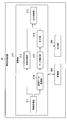
- FIG. 3 is a diagram illustrating a functional configuration example of the information processing apparatus 20 according to the embodiment of the present invention.
- the information processing apparatus 20 according to the embodiment of the present invention includes a control unit 210, a storage unit 280, and an output unit 290.
- the control unit 210 has a function of controlling the entire operation of the information processing apparatus 20.
- the storage unit 280 can store a program and data for operating the control unit 210. In addition, the storage unit 280 can temporarily store various data necessary in the course of the operation of the control unit 210.
- the output unit 290 has a function of outputting information (traffic volume, etc.) according to control by the control unit 210.
- the type of the output unit 290 is not particularly limited, and may be a display device, an audio output device, or a communication device that transmits information to the imaging device 10.
- the control unit 210 includes an image acquisition unit 211, a registration processing unit 212, an output control unit 213, a registration data acquisition unit 214, a data selection unit 215, and a measurement unit 216. Details of these functional units included in the control unit 210 will be described later.
- the functional configuration example of the information processing apparatus 20 according to the embodiment of the present invention has been described above.
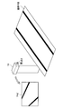
- FIG. 4 is a diagram illustrating an example of a captured image Img ′ captured by the imaging device 10 according to the embodiment of the present invention.
- the imaging device 10 and the road plane exist in real space.
- the imaging device 10 is installed in a state where the imaging direction is directed to the road plane.
- the captured image Img ′ captured by the imaging device 10 shows the boundary line of the lane provided on the road.
- the center of the lens of the imaging device 10 is set to the origin O.
- the captured image captured by the imaging device 10 is provided from the imaging device 10 to the information processing device 20.
- the captured image Img ′ captured by the imaging device 10 is acquired by the image acquisition unit 211.
- the registration processing unit 212 performs processing for registering a plurality of registered images and calibration data corresponding to each of the plurality of registered images in the storage unit 280 for each direction.
- a plurality of registered images are generated based on the captured image Img ′ will be described.
- FIG. 5 is a diagram showing parameters used by the registration processing unit 212.
- the registration processing unit 212 determines the size pix_dot of the captured image Img ′ per unit pixel of the image sensor based on the size of the image sensor that constitutes the image capturing unit 120 and the size of the captured image Img ′ provided to the control unit 210. Calculate as a parameter.
- the captured image Img ′ is generated based on the captured image Img captured on the imaging surface of the image sensor that is separated from the origin O by the focal length. Further, the captured image Img ′ provided to the control unit 210 can be used by the registration processing unit 212.
- the imaging device is a CCD (Charge Coupled Device)
- the CCD Charge Coupled Device
- the imaging element may be a CMOS (Complementary Metal Oxide Semiconductor) or the like.
- the registration processing unit 212 can calculate pix_dot by the following (Equation 1).
- the CCD size is represented by the length of the diagonal line of the CCD
- the CCD size is divided by the square root of the sum of squares in the vertical and horizontal directions of the captured image Img ′ as shown in (Equation 1). Is calculated by
- the calculation of the parameter pix_dot by such a method is only an example, and the parameter pix_dot may be calculated by another method.
- the vertical or horizontal length of the CCD may be used instead of the diagonal line of the CCD.
- the CCD size is easily acquired from the imaging unit 120, for example. Further, the size of the captured image Img ′ is acquired from the storage unit 140, for example. Therefore, the control unit 210 in the information processing apparatus 20 correlates the three-dimensional coordinates in the real space of the captured image Img captured on the imaging surface of the CCD and the two-dimensional coordinates of the captured image Img ′ based on these sizes. Can be grasped. That is, based on this correspondence, the control unit 210 in the information processing apparatus 20 grasps the three-dimensional coordinates in the real space of the captured image Img captured on the imaging surface of the CCD from the two-dimensional coordinates of the captured image Img ′. Can do.
- the road plane equation corresponding to the captured image Img ′ (hereinafter also referred to as “reference image”) can be calculated using the parameters calculated in this way.
- reference image the road plane formula corresponding to the reference image
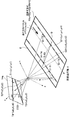
- FIG. 6 is a diagram for explaining the calculation of the road plane equation corresponding to the reference image.
- a traveling direction vector v that is a vector indicating the traveling direction of the vehicle is defined as (vx, vy, vz).
- a point (focal point) that is separated from the origin O by the focal length f is set on the y axis, and a plane that passes through this focal point and is perpendicular to the y axis is defined as an imaging surface. The description will be continued assuming that the captured image Img is captured on the imaging surface, but the setting of each coordinate axis is not limited to such an example.
- the two points through which the first straight line passes are T1 (x1, y1, z1) and T4 (x4, y4, z4), and the two points through which the second straight line passes are T2.
- T1 x1, y1, z1
- T4 x4, y4, z4
- T2 two points through which the second straight line passes
- T3 x3, y3, z3
- the coordinates of the intersections of the straight line connecting each of T1, T2, T3 and T4 and the origin O and the road plane are t1 ⁇ T1, t2 ⁇ T2, t3 ⁇ T3 and t4 ⁇ T4.
- the registration processing unit 212 can generate a road plane expression based on (Precondition 1) shown below.
- the registration processing unit 212 can derive the relational expressions shown in the following (Expression 2) and (Expression 3) based on the various data acquired as described above and (Condition 1).
- the registration processing unit 212 can derive the relational expression shown in the following (Formula 5) based on the various data acquired as described above and (Condition 3).
- the registration processing unit 212 can derive the relational expressions shown in the following (Expression 6) and (Expression 7) based on the various data acquired as described above and (Condition 4). .
- the distance from the origin O to Q1 (xr1, yr1, zr1) on the road plane is a multiple of the distance from the origin O to Q1 ′ (xs1, f, zs1) on the captured image Img. It is a value indicating whether or not
- the distance from the origin O to Q2 (xr2, yr2, zr2) on the road plane is a multiple of the distance from the origin O to Q2 ′ (xs2, f, zs2) on the captured image Img. It is a value indicating whether or not Therefore, the relational expression shown in the following (Formula 8) can be derived.
- the registration processing unit 212 can calculate the measured value Q_dis' of the distance between two points (Q1 and Q2) on the road plane from the relational expression shown in (Formula 8) by the following (Formula 9).
- the registration processing unit 212 can also calculate the road plane equation by another method. For example, if the distance between two parallel straight lines on the road plane is known, the road plane formula is calculated without using (Condition 2) by using the distance between the two parallel straight lines on the road plane. be able to.
- the registration processing unit 212 can also calculate the traveling direction vector v (vx, vy, vz). More specifically, the registration processing unit 212 can calculate the traveling direction vector v by calculating the direction of at least one of two parallel straight lines on the road plane. For example, the registration processing unit 212 may calculate the difference between the coordinates t2 ⁇ T2 and the coordinates t3 ⁇ T3 as the traveling direction vector v, or may calculate the difference between the coordinates t1 ⁇ T1 and the coordinates t4 ⁇ T4 as the traveling direction vector v. May be calculated as
- the registration processing unit 212 can calculate the road plane type and the traveling direction vector v by the method as described above. As illustrated in FIG. 6, the registration processing unit 212 may set a measurement range E. Then, the traffic volume can be measured based on the measurement range E. For example, the registration processing unit 212 may set the measurement range E based on the input operation, or may automatically set the measurement range E based on the traveling direction vector v (vx, vy, vz). . However, when the imaging range itself is the measurement range, the measurement range need not be set.
- the output control unit 213 may cause the output unit 290 to output various information calculated by the registration processing unit 212.
- the registration processing unit 212 can generate calibration data (road plane type and focal length) corresponding to the reference image by the method as described above. Further, the registration processing unit 212 corresponds to one or a plurality of images (hereinafter, also referred to as “shift images”) captured by changing the imaging direction with reference to the reference image and each of the one or more shift images. Generate calibration data.
- the registration processing unit 212 is information (hereinafter simply referred to as “the direction in which the reference image is captured) (an imaging direction), a plurality of registered images, and calibration data corresponding to each of the plurality of registered images. Is also registered in the storage unit 280.
- FIG. 7 is a diagram illustrating a registration example of correspondence information. Referring to FIG. 7, the deviation images Img11 to Img18 generated with reference to the reference image Img1 and the calibration data corresponding to each of the deviation images Img11 to Img18 and the direction D1 are associated with each other and registered in the storage unit 280. .
- the misaligned images Img21 to Img26 generated with reference to the reference image Img2 and the calibration data corresponding to the misaligned images Img21 to Img26 and the direction D2 are registered in the storage unit 280 in association with each other.
- the number of misaligned images generated by the registration processing unit 212 is not particularly limited.
- the method for generating the shifted image and the calibration data corresponding to the shifted image is not particularly limited.
- an example of generation of a calibration image corresponding to a shift image and a shift image by the registration processing unit 212 will be described.
- the three-dimensional coordinates of arbitrary five points are shown as p1 (x1, y1, z1) to p5 (x5, y5, z5).
- the registration processing unit 212 uses the two-dimensional coordinates P1 (X1, Y1) to P5 (X5, Y5) on the reference image corresponding to each of the arbitrary five points p1 to p5 as the focal length f, and Calculated by the formula.
- the registration processing unit 212 rotates each of the arbitrary points p1 (x1, y1, z1) to p5 (x5, y5, z5) p1 ′ (x1 ′, y1 ′, z1 ′).
- ... P5 ′ (x5 ′, y5 ′, z5 ′) is calculated by the following formula (10).
- ⁇ represents a roll rotation angle
- ⁇ represents a pitch rotation angle
- ⁇ represents a low rotation angle
- the registration processing unit 212 selects five points p1 ′ (x1 ′, y1 ′, z1 ′) to p5 ′.
- the two-dimensional coordinates P1 ′ (X1 ′, Y1 ′) to P5 ′ (X5 ′, Y5 ′) on the shifted images corresponding to (x5 ′, y5 ′, z5 ′) are set as the focal lengths corresponding to the shifted images.
- f + ⁇ f represents a focal distance deviation width, and may be appropriately designed according to an assumed focal distance deviation width.
- f + ⁇ f may correspond to an example of calibration data corresponding to a shifted image.
- the registration processing unit 212 selects any five points P1 (X1, Y1) to P5 (X5, Y5) in the reference image and five points P1 ′ (X1 ′, Y1 ′) to P5 ′ (X5 ′) in the shifted image. , Y5 ′) to calculate a planar projective transformation matrix. By doing so, the registration processing unit 212 can generate a shifted image by performing the planar projective transformation of the reference image using the calculated planar projective transformation matrix.
- FIG. 8 is a flowchart showing the flow of registration operation of correspondence information. Note that the flowchart shown in FIG. 8 only shows an example of the operation of registering correspondence information. Therefore, the correspondence information registration operation is not limited to the operation example shown by the flowchart of FIG.
- the image acquisition unit 211 acquires the reference image captured by the imaging device 10 and the direction of the imaging device 10 when the reference image is captured (step S11). Subsequently, the registration processing unit 212 generates calibration data corresponding to the reference image (step S12).
- the registration processing unit 212 generates a plurality of registered images and calibration data corresponding to each of the plurality of registered images based on the reference image and the calibration data corresponding to the reference image (step S13). ). Then, the registration processing unit 212 registers, in the storage unit 280, correspondence information between a plurality of registered images, calibration data corresponding to each of the plurality of registered images, and the direction of the imaging device 10 (step S14).
- the output control unit 213 may cause the output unit 290 to output various information calculated by the registration processing unit 212. Subsequently, when the registration operation is continued (“Yes” in step S15), the control unit 210 shifts the operation to step S11, but when the registration operation is not continued (“No” in step S15). End the operation.
- the flow of the correspondence information registration operation has been described above.
- the correspondence information can be registered in advance.
- the control unit 110 automatically adjusts the imaging direction to the direction selected by the selection operation by the user. Is possible. And the control part 110 starts imaging of the captured image used as the object of traffic volume measurement.
- the image acquisition unit 211 in the information processing apparatus 20 acquires this captured image.
- the registration data acquisition unit 214 acquires a registered image that matches or is similar to the captured image from a plurality of registered images registered in advance. In particular, the registration data acquisition unit 214 acquires a registered image that matches or is similar to the captured image from a plurality of registered images corresponding to the imaging direction. Then, the data selection unit 215 selects calibration data based on the registered image acquired by the registration data acquisition unit 214. For example, the data selection unit 215 may select calibration data associated with a registered image in advance.
- FIG. 9 is a diagram illustrating an example of selecting calibration data.
- a captured image Img-x that is a traffic measurement target is acquired by the image acquisition unit 211, and a plurality of misaligned images Img15 similar to Img-x correspond to the imaging direction D1 by the registered data acquisition unit 214.
- An example obtained from the registered images (reference image Img1, shift images Img11 to Img18) is shown.
- An example is shown in which the data selection unit 215 selects calibration data associated with the misaligned image Img15.
- the registered data acquisition unit 214 determines whether or not each of the plurality of registered images matches or is similar to the captured image, but the determination method is not particularly limited.
- the registration data acquisition unit 214 may extract a feature amount from each of the plurality of registered images and the captured image, and determine that the registered image and the captured image whose feature amount similarity exceeds a threshold match or are similar.
- the method for extracting the feature amount is not particularly limited.
- a line for example, a lane boundary of a road or a boundary between a wall and a road
- the method for calculating the similarity is not particularly limited.
- a cross correlation method may be used for calculating the similarity.
- the registered data acquisition unit 214 may acquire the registered image having the highest similarity with the captured image.
- the registered data acquisition unit 214 does not have to acquire a registered image when there is no registered image that matches or is similar to the captured image. In such a case, calibration data need not be selected, and traffic volume measurement need not be continued or started.
- the plurality of registered images that can be acquired by the registered data acquiring unit 214 may not be changed, or may be changed based on the acquisition result by the registered data acquiring unit 214.
- the registered image acquisition unit 214 acquires the shifted image Img15
- a new image is obtained as a registered image that can be acquired by the registered data acquiring unit 214 based on the shifted image Img15. May be.
- the measuring unit 216 measures the traffic volume from the captured image captured by the imaging device 10 using calibration data.
- the traffic measurement method is not particularly limited.
- FIG. 10 is a diagram illustrating an example of a method for measuring traffic volume using calibration data.
- the measurement unit 216 detects a predetermined detection position (for example, coordinates of a predetermined position of the vehicle on the vehicle travel axis X15) based on the vehicle region extracted from the captured image, and calculates the traffic volume based on the detection position. You may measure. Alternatively, the measurement unit 216 may measure the traffic volume by other methods.
- the timing for starting traffic measurement is not particularly limited.
- the measurement unit 216 automatically continues or starts measuring traffic because it is considered that effective calibration data can be acquired when a registered image that matches or is similar to the captured image is acquired. Also good.
- the timing which stops the measurement of traffic volume is not specifically limited.
- the measurement unit 216 may not be able to acquire effective calibration data when a registered image that matches or is similar to the captured image is not acquired. Good.
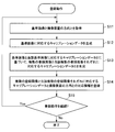
- FIG. 11 is a flowchart showing the flow of the traffic measurement operation.
- the flowchart shown in FIG. 11 only showed an example of the traffic measurement operation. Therefore, the traffic measurement operation is not limited to the operation example shown by the flowchart of FIG.
- the image acquisition unit 211 acquires the imaging direction of the imaging device 10 (step S21), and acquires the captured image captured by the imaging device 10 (step S22). Subsequently, the registration data acquisition unit 214 acquires a registered image that matches or is similar to the captured image from a plurality of registered images corresponding to the imaging direction acquired by the image acquisition unit 211 (step S23).
- the data selection unit 215 selects calibration data associated with the registered image acquired by the registration data acquisition unit 214 (step S24).
- the measuring unit 216 measures the traffic volume using the calibration data (step S25).
- the output control unit 213 may cause the output unit 290 to output the traffic volume measured by the measurement unit 216. Subsequently, when the measurement operation is continued (“Yes” in step S26), the control unit 210 shifts the operation to step S21, but when the measurement operation is not continued (“No” in step S26). End the operation.
- the traffic volume measurement operation has been described above.
- the image acquisition unit 211 that acquires a captured image captured by the imaging device 10 and a plurality of registered images that are registered in advance match or are similar to the captured image.
- a registration data acquisition unit 214 that acquires a registered image to be performed, and a data selection unit 215 that selects predetermined calibration data necessary for measuring the traffic volume from the captured image captured by the imaging device 10 based on the registered image.
- An information processing apparatus 20 is provided.
- the imaging device 10 When a predetermined selection operation is input, the imaging device 10 automatically adjusts the imaging direction to the direction selected by the selection operation, and the registration data acquisition unit 214 selects a registered image that matches or is similar to the captured image. Obtained from a plurality of registered images corresponding to the imaging direction.
- the information processing apparatus 20 may determine whether or not the imaging apparatus 10 has failed based on the acquisition frequency for each registered image by the registration data acquisition unit 214. For example, the information processing apparatus 20 determines whether or not the imaging apparatus 10 is out of order based on the frequency at which a predetermined registered image (for example, a shifted image) is acquired by the registered data acquisition unit 214 among a plurality of registered images. May be judged.
- a predetermined registered image for example, a shifted image
- the imaging device 10 is out of order when the frequency at which a predetermined registered image is acquired by the registered data acquisition unit 214 among a plurality of registered images exceeds a threshold value. You may judge. In such a case, the output control unit 213 may output that the imaging device 10 has failed. In addition, the output control unit 213 may output a registered image whose acquisition frequency exceeds a threshold value together with the fact that the imaging device 10 has failed or instead of the fact that the imaging device 10 has failed.
- the information processing apparatus 20 can also detect the period of vibration applied to the imaging apparatus 10 by analyzing the temporal change of the registered image acquired by the registered data acquisition unit 214.
- the vibration applied to the imaging apparatus 10 may be vibration applied to the imaging apparatus 10 due to an earthquake or the like.
- the output control unit 213 may output the period of vibration given to the imaging device 10.
- the type of reference image registered in advance and its calibration data are not particularly limited.
- a plurality of reference images having different imaging times and calibration data corresponding to them may be registered. If it does so, it becomes possible to strengthen tolerance to the change of the traffic volume by the weather, and the change of the traffic volume by the time.
- a plurality of reference images captured by changing the installation position of the imaging device 10 and calibration data corresponding to them may be registered. Then, it becomes possible to perform traffic volume measurement at a plurality of positions.
- the registration data acquisition unit 214 automatically generates a plurality of registration images.
- the registration data acquisition unit 214 may not automatically generate a plurality of registration images.
- a plurality of registered images may be captured by the user performing an imaging operation while manually shifting the imaging direction of the imaging device 10.
- Each block that configures the control unit 110 includes, for example, a CPU (Central Processing Unit), a RAM (Random Access Memory), and the program stored in the storage unit 140 is expanded and executed by the CPU. Thus, the function can be realized. Or each block which comprises the control part 110 may be comprised by the hardware for exclusive use, and may be comprised by the combination of several hardware.
- a CPU Central Processing Unit
- RAM Random Access Memory
- Each block configuring the control unit 210 includes, for example, a CPU (Central Processing Unit), a RAM (Random Access Memory), and the program stored in the storage unit 280 is expanded into the RAM by the CPU and executed. Thus, the function can be realized. Or each block which comprises the control part 210 may be comprised by the hardware for exclusive use, and may be comprised by the combination of several hardware.
- a CPU Central Processing Unit
- RAM Random Access Memory
Landscapes
- Physics & Mathematics (AREA)
- General Physics & Mathematics (AREA)
- Engineering & Computer Science (AREA)
- Multimedia (AREA)
- Signal Processing (AREA)
- Traffic Control Systems (AREA)
- Closed-Circuit Television Systems (AREA)
Abstract
【課題】自動的に合わせられた撮像方向に対応するキャリブレーションデータをより迅速に補正することが可能な技術を提供する。 【解決手段】あらかじめ登録された複数の登録画像から、撮像画像に一致または類似する登録画像を取得する登録データ取得部214と、撮像装置10によって撮像された撮像画像から交通量を計測するために必要な所定のキャリブレーションデータを、登録画像に基づいて選択するデータ選択部215と、を備え、撮像装置10は、所定の選択操作が入力されると、当該選択操作によって選択される方向に自動的に撮像方向を合わせ、登録データ取得部214は、撮像画像に一致または類似する登録画像を、撮像方向に対応する複数の登録データから取得する、情報処理装置20が提供される。
Description
本発明は、情報処理装置、情報処理方法およびプログラムに関するものである。
近年、撮像画像から走行車両の量(以下、「交通量」とも言う。)を計測する技術が開発されている。交通量を計測するに当たっては、撮像装置のキャリブレーションデータを生成する必要がある。ここで、キャリブレーションデータを生成する技術には様々な技術が知られている。例えば、撮像画像に映る車両の特定部位の軌跡と車両のフロントガラスの勾配とに基づいてキャリブレーションデータを生成する技術が開示されている(例えば、非特許文献1参照)。
一方、近年では、撮像装置として、パン・チルト・ズーム機能(以下、単に「PTZ機能」とも言う。)を有する撮像装置が利用される機会が増えてきている。PTZ機能を有する撮像装置には、あらかじめ1または複数の方向を設定しておくことが可能であり(以下、「プリセット」とも言う。)、ユーザによる選択操作がなされると、PTZ機能を有する撮像装置は、ユーザによる選択操作によって選択される方向に自動的に撮像方向を合わせることが可能である。そして、自動的に合わせられた撮像方向に従って撮像された撮像画像から交通量が計測される。
このようなPTZ機能を有する撮像装置が交通量の計測に用いられる場合、それぞれのプリセットされた方向に対応するキャリブレーションデータを生成して登録しておく動作(以下、「キャリブレーション」とも言う。)があらかじめ行われているとよい。かかるキャリブレーションが行われていれば、交通量の計測時点において自動的に合わせられた撮像方向に対応するキャリブレーションデータを取得すればよいため、キャリブレーションデータを生成する時間を低減することが可能である。
Neeraj K. Kanhere, Stanley T. Birchfield, Wayne A. Sarasua"Automatic Camera Calibration Using Pattern Detection for Vision-Based SpeedSensing" Transportation Research Board Annual Meeting, Washington, D.C.,January 2008
しかしながら、撮像装置のPTZ機能を制御する駆動機構の機械的な精度等により、プリセットされた撮像方向に撮像装置が向けられたとしても、キャリブレーションが行われた時点と交通量の計測時点とにおいて、撮像装置の設置位置は完全に一致しているとは限らない。したがって、自動的に合わせられた撮像方向に対応するキャリブレーションデータが事前に取得されたとしても、取得されたキャリブレーションデータの精度は十分ではない可能性がある。また、自動的に合わせられた撮像方向に従って撮像された撮像画像からキャリブレーションデータを生成し直せば、キャリブレーションデータを生成する時間を要してしまう。
そこで、本発明は、上記問題に鑑みてなされたものであり、本発明の目的とするところは、自動的に合わせられた撮像方向に対応するキャリブレーションデータをより迅速に補正することが可能な技術を提供することにある。
上記問題を解決するために、本発明のある観点によれば、撮像装置によって撮像された撮像画像を取得する画像取得部と、あらかじめ登録された複数の登録データから、前記撮像画像または前記撮像画像から得られる特徴量に一致または類似する登録データを取得する登録データ取得部と、前記撮像装置によって撮像された撮像画像から交通量を計測するために必要な所定のキャリブレーションデータを、前記登録データに基づいて選択するデータ選択部と、を備え、前記撮像装置は、所定の選択操作が入力されると、当該選択操作によって選択される方向に自動的に撮像方向を合わせ、前記登録データ取得部は、前記撮像画像または前記撮像画像から得られる特徴量に一致または類似する登録データを、前記撮像方向に対応する複数の登録データから取得する、情報処理装置が提供される。
前記データ選択部は、あらかじめ前記登録データに対応付けられたキャリブレーションデータを選択してよい。
前記撮像装置は、前記所定の選択操作によって、前記撮像方向として複数の方向の何れかを選択可能であり、前記情報処理装置は、前記複数の方向それぞれについて複数の登録データを記憶する記憶部を備えてよい。
前記登録データ取得部は、前記複数の登録データそれぞれと前記撮像画像または前記撮像画像から得られる特徴量との類似度を算出し、算出した類似度が閾値を超える登録データと前記撮像画像または前記撮像画像から得られる特徴量とが類似していると判断してよい。
前記情報処理装置は、前記撮像装置によって撮像された撮像画像から前記キャリブレーションデータを用いて交通量を計測する計測部を備えてよい。
前記計測部は、前記撮像画像または前記撮像画像から得られる特徴量に一致または類似する登録データが取得された場合には、前記交通量の計測を自動的に継続または開始してよい。
前記計測部は、前記撮像画像または前記撮像画像から得られる特徴量に一致または類似する登録データが取得されなかった場合には、前記交通量の計測を停止してよい。
前記複数の登録データそれぞれは、画像および当該画像から得られる特徴量の少なくとも何れか一方を含んでよい。
前記キャリブレーションデータは、前記撮像装置によって撮像された撮像画像に映る道路の平面式および前記撮像装置の焦点距離のうち少なくとも何れか一方を含んでよい。
前記情報処理装置は、前記複数の登録データと前記複数の登録データそれぞれに対応するキャリブレーションデータとを記憶部に登録する登録処理部を備えてよい。
前記登録処理部は、所定の基準データおよび前記基準データに対応するキャリブレーションデータに基づいて、前記複数の登録データと前記複数の登録データそれぞれに対応するキャリブレーションデータとを生成してよい。
また、本発明のある観点によれば、撮像装置によって撮像された撮像画像を取得するステップと、あらかじめ登録された複数の登録データから、前記撮像画像または前記撮像画像から得られる特徴量に一致または類似する登録データを取得するステップと、前記撮像装置によって撮像された撮像画像から交通量を計測するために必要な所定のキャリブレーションデータを、前記登録データに基づいて選択するステップと、を含み、前記撮像装置は、所定の選択操作が入力されると、当該選択操作によって選択される方向に自動的に撮像方向を合わせ、前記撮像画像または前記撮像画像から得られる特徴量に一致または類似する登録データを、前記撮像方向に対応する複数の登録データから取得するステップを含む、情報処理方法が提供される。
また、本発明のある観点によれば、コンピュータを、撮像装置によって撮像された撮像画像を取得する画像取得部と、あらかじめ登録された複数の登録データから、前記撮像画像または前記撮像画像から得られる特徴量に一致または類似する登録データを取得する登録データ取得部と、前記撮像装置によって撮像された撮像画像から交通量を計測するために必要な所定のキャリブレーションデータを、前記登録データに基づいて選択するデータ選択部と、を備え、前記撮像装置は、所定の選択操作が入力されると、当該選択操作によって選択される方向に自動的に撮像方向を合わせ、前記データ選択部は、前記撮像画像または前記撮像画像から得られる特徴量に一致または類似する登録データを、前記撮像方向に対応する複数の登録データから取得する、情報処理装置として機能させるためのプログラムが提供される。
以上説明したように本発明によれば、自動的に合わせられた撮像方向に対応するキャリブレーションデータをより迅速に補正することが可能である。
以下に添付図面を参照しながら、本発明の好適な実施の形態について詳細に説明する。なお、本明細書および図面において、実質的に同一の機能構成を有する構成要素については、同一の符号を付することにより重複説明を省略する。
また、本明細書および図面において、実質的に同一の機能構成を有する複数の構成要素を、同一の符号の後に異なるアルファベットまたは数字を付して区別する場合もある。ただし、実質的に同一の機能構成を有する複数の構成要素の各々を特に区別する必要がない場合、同一符号のみを付する。
[構成の説明]
まず、本発明の実施形態の構成を説明する。図1は、本発明の実施形態に係る交通量計測システム1の構成例を示す図である。図1に示すように、本発明の実施形態に係る交通量計測システム1は、撮像装置10および情報処理装置20を備える。撮像装置10と情報処理装置20との間は、有線または無線によって接続されている。
まず、本発明の実施形態の構成を説明する。図1は、本発明の実施形態に係る交通量計測システム1の構成例を示す図である。図1に示すように、本発明の実施形態に係る交通量計測システム1は、撮像装置10および情報処理装置20を備える。撮像装置10と情報処理装置20との間は、有線または無線によって接続されている。
図1に示すように、撮像装置10は、道路平面を撮像可能に設置されており、撮像した画像を情報処理装置20に提供することが可能である。図1に示した例では、道路平面上を車両Mが走行している。情報処理装置20は、撮像装置10から提供された撮像画像から交通量を計測する。
さらに、撮像装置10はPTZ機能を有している。すなわち、図1に示すように、パン(撮像方向の左右振り)機能、チルト(撮像方向の上下振り)機能およびズーム(撮像範囲の拡大縮小)機能を有している。撮像装置10には、あらかじめ1または複数の方向を設定しておくことが可能であり、ユーザによる選択操作がなされると、撮像装置10は、ユーザによる選択操作によって選択される方向に自動的に撮像方向を合わせることが可能である。
撮像装置10が交通量の計測に用いられる場合には、プリセットがあらかじめ行われているのがよい。プリセットがあらかじめ行われていれば、情報処理装置20は、交通量の計測時点において自動的に合わせられた撮像方向に対応するキャリブレーションデータを取得すればよい。そのため、キャリブレーションデータを生成する時間を低減することが可能である。
しかしながら、撮像装置10のPTZ機能を制御する駆動機構の機械的な精度等により、プリセットされた撮像方向に撮像装置10が向けられたとしても、キャリブレーションが行われた時点と交通量の計測時点とにおいて、撮像装置10の設置位置は完全に一致しているとは限らない。したがって、自動的に合わせられた撮像方向に対応するキャリブレーションデータが事前に取得されたとしても、取得されたキャリブレーションデータの精度は十分ではない可能性がある。また、交通量の計測時点において撮像装置10が何らかの理由(例えば、強風、振動、地震など)で揺れた場合にも、取得されたキャリブレーションデータの精度が低下してしまう可能性がある。
また、自動的に合わせられた撮像方向に従って撮像された撮像画像からキャリブレーションデータを生成し直せば、キャリブレーションデータを生成する時間を要してしまう。特に、上記した非特許文献1に記載された技術を用いてキャリブレーションデータを生成する場合には、撮像画像に車両が映るまでキャリブレーションデータを生成することができないため、キャリブレーションデータを生成するために多くの時間を費やしてしまう。
そこで、本明細書においては、自動的に合わせられた撮像方向に対応するキャリブレーションデータをより迅速に補正することが可能な技術を主に提案する。キャリブレーションデータが迅速に補正されれば、撮像装置10の揺れへの耐性も強くなる。なお、本明細書においては、キャリブレーションデータの例として、道路平面式および焦点距離を用いるが、キャリブレーションデータの種類は特に限定されない。例えば、キャリブレーションデータは、道路平面式および焦点距離のうち何れか一方を含んでいてもよい。以上、交通量計測システム1の構成例について説明した。
続いて、撮像装置10の機能構成例を説明する。図2は、本発明の実施形態に係る撮像装置10の機能構成例を示す図である。図2に示すように、本発明の実施形態に係る撮像装置10は、制御部110、撮像部120、操作部130、記憶部140および出力部150を備える。
制御部110は、撮像装置10の動作全体を制御する機能を有する。また、撮像部120は、実空間を撮像することにより撮像画像を取得する機能を有し、例えば、単眼カメラにより構成される。操作部130は、ユーザからの各種操作の入力を受け付ける機能を有する。
記憶部140は、制御部110を動作させるためのプログラムやデータを記憶することができる。また、記憶部140は、制御部110の動作の過程で必要となる各種データを一時的に記憶することもできる。出力部150は、制御部110による制御に従って出力を行う機能を有する。出力部150の種類は特に限定されず、表示装置であってもよいし、音声出力装置であってもよいし、情報処理装置20への情報送信を行う通信装置であってもよい。
なお、図2に示した例では、撮像部120、操作部130、記憶部140および出力部150は、撮像装置10の内部に存在するが、撮像部120、操作部130、記憶部140および出力部150の全部または一部は、撮像装置10の外部に備えられていてもよい。以上、本発明の実施形態に係る撮像装置10の機能構成例について説明した。
続いて、本発明の実施形態に係る情報処理装置20の機能構成について説明する。図3は、本発明の実施形態に係る情報処理装置20の機能構成例を示す図である。図3に示すように、本発明の実施形態に係る情報処理装置20は、制御部210、記憶部280および出力部290を備える。
制御部210は、情報処理装置20の動作全体を制御する機能を有する。記憶部280は、制御部210を動作させるためのプログラムやデータを記憶することができる。また、記憶部280は、制御部210の動作の過程で必要となる各種データを一時的に記憶することもできる。出力部290は、制御部210による制御に従って情報(交通量など)の出力を行う機能を有する。出力部290の種類は特に限定されず、表示装置であってもよいし、音声出力装置であってもよいし、撮像装置10への情報送信を行う通信装置であってもよい。
なお、図3に示した例では、記憶部280および出力部290は、情報処理装置20の内部に存在するが、記憶部280および出力部290の全部または一部は、情報処理装置20の外部に備えられていてもよい。また、制御部210は、画像取得部211と、登録処理部212と、出力制御部213と、登録データ取得部214と、データ選択部215と、計測部216とを備える。制御部210が備えるこれらの各機能部の詳細については、後に説明する。以上、本発明の実施形態に係る情報処理装置20の機能構成例について説明した。
[対応情報の登録]
続いて、本発明の実施形態の詳細を説明する。図4は、本発明の実施形態に係る撮像装置10によって撮像される撮像画像Img’の例を示す図である。図4に示すように、撮像装置10および道路平面が実空間に存在する。撮像装置10は、撮像方向が道路平面に向けられた状態で設置されている。撮像装置10により撮像された撮像画像Img’には道路に設けられたレーンの境界線が映っている。また、図4に示すように、撮像装置10のレンズの中心が原点Oに設定されている。撮像装置10によって撮像された撮像画像は、撮像装置10から情報処理装置20に提供される。
続いて、本発明の実施形態の詳細を説明する。図4は、本発明の実施形態に係る撮像装置10によって撮像される撮像画像Img’の例を示す図である。図4に示すように、撮像装置10および道路平面が実空間に存在する。撮像装置10は、撮像方向が道路平面に向けられた状態で設置されている。撮像装置10により撮像された撮像画像Img’には道路に設けられたレーンの境界線が映っている。また、図4に示すように、撮像装置10のレンズの中心が原点Oに設定されている。撮像装置10によって撮像された撮像画像は、撮像装置10から情報処理装置20に提供される。
続いて、情報処理装置20の機能詳細について説明する。まず、撮像装置10によって撮像された撮像画像Img’が画像取得部211によって取得される。そして、登録処理部212によって複数の登録画像と当該複数の登録画像それぞれに対応するキャリブレーションデータとを方向ごとに記憶部280に登録する処理が行われる。なお、本明細書においては、撮像画像Img’を基準として複数の登録画像を生成する例を説明する。
図5は、登録処理部212により使用されるパラメータを示す図である。登録処理部212は、撮像部120を構成する撮像素子のサイズと制御部210に提供される撮像画像Img’のサイズとに基づいて、撮像素子の単位pixel当たりの撮像画像Img’のサイズpix_dotをパラメータとして算出する。撮像画像Img’は、原点Oから焦点距離だけ離れた撮像素子の撮像面上に撮像された撮像画像Imgに基づいて生成される。また、制御部210に提供された撮像画像Img’は、登録処理部212によって利用され得る。
図5に示すように、ここでは、撮像素子がCCD(Charge Coupled Device)である場合を例として説明するが、CCDは撮像素子の一例に過ぎない。したがって、撮像素子はCMOS(Complementary Metal Oxide Semiconductor)等であってもよい。
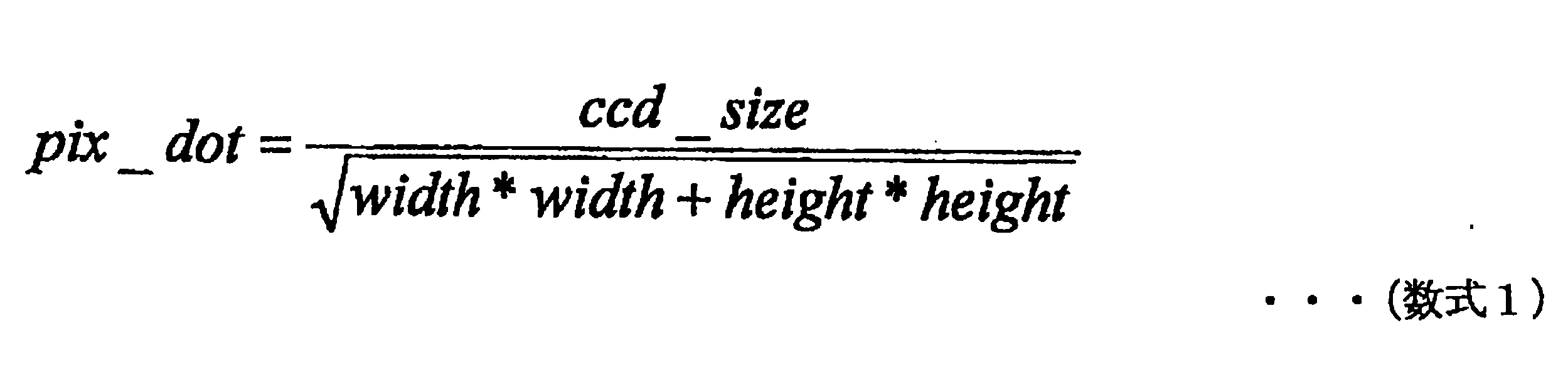
ここで、CCDサイズをccd_sizeとし、撮像画像Img’(横:width×縦:height)のサイズをimg_sizeとすると、登録処理部212は、以下の(数式1)によりpix_dotを算出することができる。一般的に、CCDサイズは、CCDの対角線の長さで表されるため、この(数式1)に示されるように、CCDサイズが撮像画像Img’の縦横の2乗和の平方根で除されることにより算出される。しかし、このような手法によるパラメータpix_dotの算出は一例に過ぎないため、他の手法によりパラメータpix_dotが算出されてもよい。例えば、CCDの対角線の代わりにCCDの縦または横の長さが用いられてもよい。
なお、CCDサイズは、例えば、撮像部120から容易に取得される。また、撮像画像Img’のサイズは、例えば、記憶部140から取得される。したがって、情報処理装置20における制御部210は、これらのサイズに基づいて、CCDの撮像面に撮像される撮像画像Imgの実空間における3次元座標と撮像画像Img’の2次元座標との対応関係を把握することができる。すなわち、情報処理装置20における制御部210は、この対応関係に基づいて、撮像画像Img’の2次元座標からCCDの撮像面に撮像される撮像画像Imgの実空間における3次元座標を把握することができる。
このように算出されたパラメータを用いて撮像画像Img’(以下、「基準画像」とも言う。)に対応する道路平面式が算出され得る。以下、図6を参照しながら、基準画像に対応する道路平面式の算出について説明する。図6は、基準画像に対応する道路平面式の算出について説明するための図である。
図6に示したように、原点Oを基準としたxyz座標系(実空間)を想定する。このxyz座標系において、道路平面式をR1x+R2x+R3z+R4=0とする。また、車両の進行方向を示すベクトルである進行方向ベクトルvを(vx,vy,vz)とする。なお、以下の説明では、図6に示したように、原点Oから焦点距離fだけ離れた点(焦点)をy軸上に設定し、この焦点を通りy軸に垂直な平面を撮像面とし、この撮像面上に撮像画像Imgが撮像されるものとして説明を続けるが、各座標軸の設定はこのような例に限定されない。
道路平面上には、平行な2直線があらかじめ描かれている。したがって、撮像画像Imgには、この平行な2直線が映されている。また、道路平面上には、既知の大きさQ_dis離れた2点Q1,Q2があらかじめ描かれている。撮像画像Imgには、2点Q1,Q2が、Q1’(xs1,f,zs1),Q2’(xs2,f,zs2)として映される。なお、図6に示した例では、Q1,Q2が道路平面上の平行な2直線の各々上の点として描かれているが、Q1,Q2は、道路平面上の点であれば、特に限定されない。
また、撮像画像Imgに映る2直線のうち、第1の直線が通る2点をT1(x1,y1,z1)およびT4(x4,y4,z4)とし、第2の直線が通る2点をT2(x2,y2,z2)およびT3(x3,y3,z3)とする。すると、図6に示すように、T1、T2、T3およびT4の各々と原点Oとを結ぶ直線と道路平面との交点の座標は、t1・T1、t2・T2、t3・T3およびt4・T4と表される。登録処理部212は、例えば、以下に示す(前提条件1)に基づいて、道路平面式を生成することができる。
(前提条件1)
(条件1)道路平面上の平行な2直線の方向ベクトルは同じである。
(条件2)撮像装置10のロールは0である。
(条件3)原点Oから道路平面までの距離を高さHとする。
(条件4)道路平面上にQ_dis離れたQ1およびQ2が存在する。
なお、上記ロールが0である状態とは、道路平面に対して垂直な方向に設置されている物体が撮像画像Img上においても縦方向に映るように物体が設置されている状態を意味する。
(条件1)道路平面上の平行な2直線の方向ベクトルは同じである。
(条件2)撮像装置10のロールは0である。
(条件3)原点Oから道路平面までの距離を高さHとする。
(条件4)道路平面上にQ_dis離れたQ1およびQ2が存在する。
なお、上記ロールが0である状態とは、道路平面に対して垂直な方向に設置されている物体が撮像画像Img上においても縦方向に映るように物体が設置されている状態を意味する。
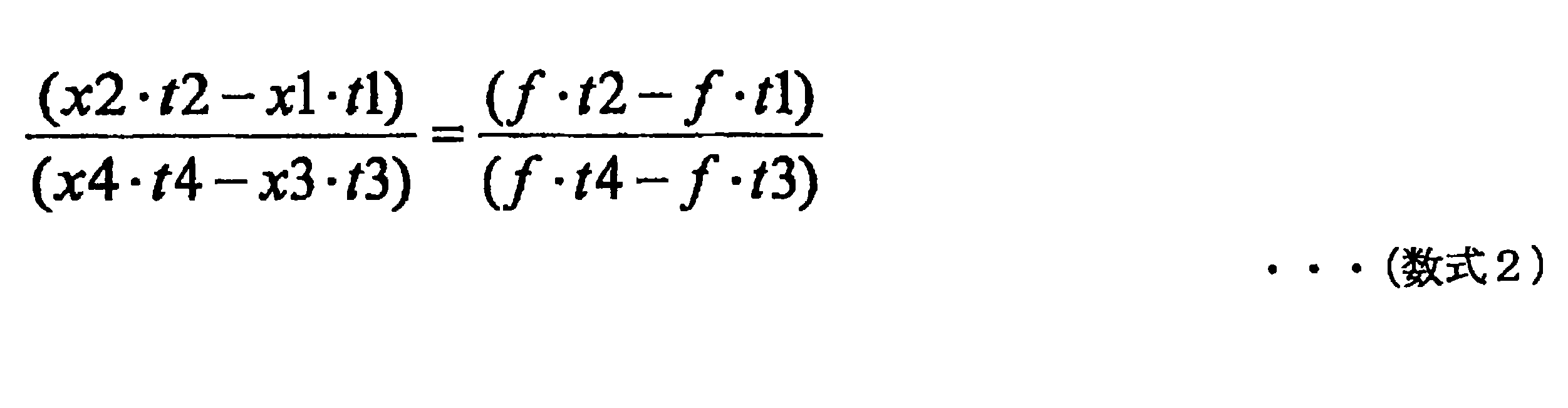
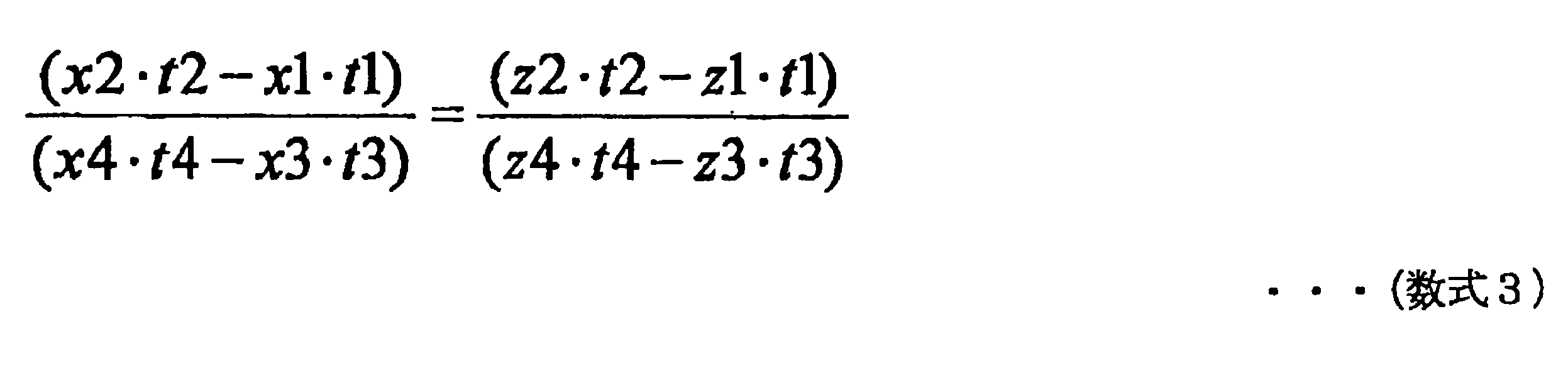
登録処理部212は、以上に示したように取得される各種データと(条件1)とに基づいて、以下の(数式2)および(数式3)に示される関係式を導き出すことができる。
また、登録処理部212は、以上に示したように取得される各種データと(条件2)とに基づいて、以下の(数式4)に示される関係式を導き出すことができる。なお、ロールが0の状態であれば、道路平面式と平行な軸方向(図6に示した例では、x軸方向)への道路平面に対する垂線の成分が0になるため、計算式が簡略化される(例えば、x軸方向への垂線の成分が0であれば、R1=0として計算できる)。

また、登録処理部212は、以上に示したように取得される各種データと(条件3)とに基づいて、以下の(数式5)に示される関係式を導き出すことができる。

また、登録処理部212は、以上に示したように取得される各種データと(条件4)とに基づいて、以下の(数式6)および(数式7)に示される関係式を導き出すことができる。

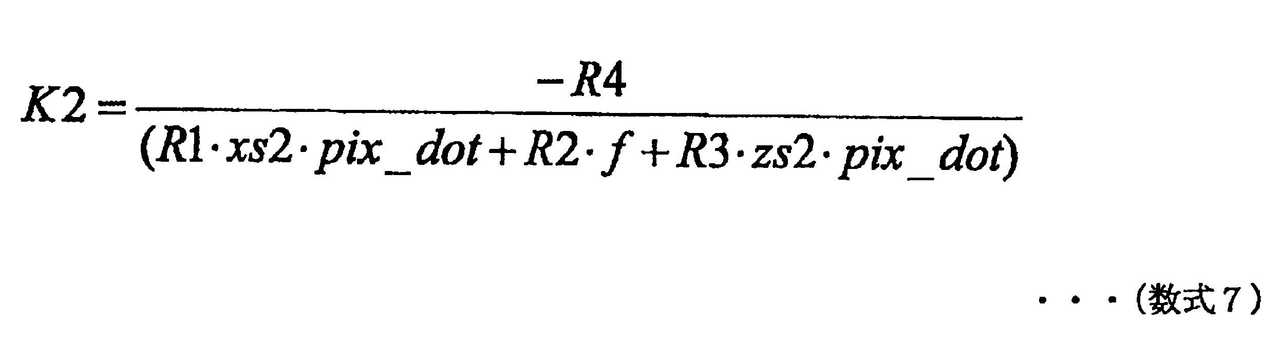
ここで、K1は、原点Oから道路平面上のQ1(xr1,yr1,zr1)までの距離が原点Oから撮像画像Img上のQ1’(xs1,f,zs1)までの距離の何倍になっているかを示す値である。同様に、K2は、原点Oから道路平面上のQ2(xr2,yr2,zr2)までの距離が原点Oから撮像画像Img上のQ2’(xs2,f,zs2)までの距離の何倍になっているかを示す値である。したがって、以下の(数式8)に示される関係式を導き出すことができる。

登録処理部212は、(数式8)に示される関係式から、道路平面上の2点(Q1およびQ2)の距離の測定値Q_dis’を、以下の(数式9)により算出することができる。

登録処理部212は、測定値Q_dis’と既知の大きさQ_disとの差分が最も小さくなる場合におけるR1、R2、R3およびR4を、(数式1)~(数式9)に基づいて算出することができる。このようにR1、R2、R3およびR4が算出されることにより、道路平面式R1x+R2x+R3z+R4=0が決定される。
以上に説明したような道路平面式の算出手法は、一例に過ぎない。したがって、登録処理部212は、他の手法により道路平面式を算出することも可能である。例えば、道路平面上の平行な2直線間の距離が既知であれば、この道路平面上の平行な2直線間の距離を用いることにより、(条件2)を使用しないで道路平面式を算出することができる。
また、登録処理部212は、進行方向ベクトルv(vx,vy,vz)を算出することもできる。より詳細には、登録処理部212は、道路平面上の平行な2直線のうちの少なくともいずれか一方の直線の方向を算出することにより、進行方向ベクトルvを算出することができる。例えば、登録処理部212は、座標t2・T2と座標t3・T3との差分を進行方向ベクトルvとして算出してもよいし、座標t1・T1と座標t4・T4との差分を進行方向ベクトルvとして算出してもよい。
以上に説明したような手法により、登録処理部212は、道路平面式および進行方向ベクトルvを算出することができる。また、図6に示すように、登録処理部212は、計測範囲Eを設定してもよい。そうすれば、計測範囲Eに基づいて交通量が計測され得る。例えば、登録処理部212は、入力操作に基づいて計測範囲Eを設定してもよいし、進行方向ベクトルv(vx,vy,vz)に基づいて自動的に計測範囲Eを設定してもよい。ただし、撮像範囲自体を計測範囲とする場合などには、計測範囲の設定は特になされなくてもよい。出力制御部213は、登録処理部212によって算出された各種情報を出力部290に出力させてもよい。
以上に示したような手法により、登録処理部212は、基準画像に対応するキャリブレーションデータ(道路平面式および焦点距離)を生成することが可能である。また、登録処理部212は、基準画像を基準として撮像方向を変更して撮像された1または複数の画像(以下、「ずれ画像」とも言う。)と当該1または複数のずれ画像それぞれに対応するキャリブレーションデータを生成する。
そして、登録処理部212は、基準画像を撮像したときの方向(撮像方向)と複数の登録画像と当該複数の登録画像それぞれに対応するキャリブレーションデータとが対応付けられた情報(以下、単に「対応情報」とも言う。)を記憶部280に登録する。図7は、対応情報の登録例を示す図である。図7を参照すると、基準画像Img1を基準として生成されたずれ画像Img11~Img18とずれ画像Img11~Img18それぞれに対応するキャリブレーションデータと方向D1とが対応付けられて記憶部280に登録されている。
また、図7を参照すると、基準画像Img2を基準として生成されたずれ画像Img21~Img26とずれ画像Img21~Img26それぞれに対応するキャリブレーションデータと方向D2とが対応付けられて記憶部280に登録されている。なお、登録処理部212によって生成されるずれ画像の数は特に限定されない。また、ずれ画像およびずれ画像に対応するキャリブレーションデータを生成する手法も特に限定されない。以下に、登録処理部212によるずれ画像およびずれ画像に対応するキャリブレーションデータの生成の一例を説明する。
まず、登録処理部212は、基準画像に対応する道路平面式R1x+R2y+R3z+R4=0によって示される道路平面上における任意の5点以上を求める。ここでは、任意の5点の3次元座標を、p1(x1,y1,z1)~p5(x5,y5,z5)として示す。続いて、登録処理部212は、任意の5点p1~p5それぞれに対応する基準画像上の2次元座標P1(X1,Y1)~P5(X5,Y5)を、焦点距離をfとして、以下の式によって算出する。
X=x×f/y
Y=z×f/y
Y=z×f/y
続いて、登録処理部212は、任意の5点p1(x1,y1,z1)~p5(x5,y5,z5)を回転させた後の各点p1’(x1’,y1’,z1’)~p5’(x5’,y5’,z5’)を、以下の数式(10)によって算出する。ただし、θはロール回転角、φはピッチ回転角、Ψはロー回転角を表しており、これらの角度は、想定されるずれ幅に応じて適宜に設計されてよい。

続いて、登録処理部212は、ベクトルp1’p2’とベクトルp1’p3’との外積によって、ずれ画像の道路平面式R1’x+R2’y+R3’z+R4’=0の係数であるR1’、R2’およびR3’を算出する。また、登録処理部212は、点p1’をずれ画像の道路平面式R1’x+R2’y+R3’z+R4’=0に代入すると、R4’を算出することができる。このようにして、ずれ画像の道路平面式がキャリブレーションデータの一例として算出され得る。
続いて、登録処理部212は、5点p1’(x1’,y1’,z1’)~p5’
(x5’,y5’,z5’)それぞれに対応するずれ画像上の2次元座標P1’(X1’,Y1’)~P5’(X5’,Y5’)を、ずれ画像に対応する焦点距離をf+Δfとして、以下の式によって算出する。ただし、Δfは焦点距離のずれ幅を示しており、想定される焦点距離のずれ幅に応じて適宜に設計されてよい。f+Δfは、ずれ画像に対応するキャリブレーションデータの一例に相当し得る。
(x5’,y5’,z5’)それぞれに対応するずれ画像上の2次元座標P1’(X1’,Y1’)~P5’(X5’,Y5’)を、ずれ画像に対応する焦点距離をf+Δfとして、以下の式によって算出する。ただし、Δfは焦点距離のずれ幅を示しており、想定される焦点距離のずれ幅に応じて適宜に設計されてよい。f+Δfは、ずれ画像に対応するキャリブレーションデータの一例に相当し得る。
X’=x’×(f+Δf)/y’
Y’=z’×(f+Δf)/y’
Y’=z’×(f+Δf)/y’
続いて、登録処理部212は、基準画像における任意の5点P1(X1,Y1)~P5(X5,Y5)とずれ画像における5点P1’(X1’,Y1’)~P5’(X5’,Y5’)とを用いて平面射影変換行列を算出する。そうすれば、登録処理部212は、算出した平面射影変換行列によって基準画像を平面射影変換すると、ずれ画像を生成することができる。
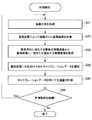
続いて、対応情報の登録動作の流れについて説明する。図8は、対応情報の登録動作の流れを示すフローチャートである。なお、図8に示したフローチャートは、対応情報の登録動作の一例を示したに過ぎない。したがって、対応情報の登録動作は、図8のフローチャートによって示される動作例に限定されない。
まず、画像取得部211は、撮像装置10によって撮像された基準画像と基準画像を撮像したときの撮像装置10の方向とを取得する(ステップS11)。続いて、登録処理部212は、基準画像に対応するキャリブレーションデータを生成する(ステップS12)。
続いて、登録処理部212は、基準画像と当該基準画像に対応するキャリブレーションデータとに基づいて、複数の登録画像と当該複数の登録画像それぞれに対応するキャリブレーションデータとを生成する(ステップS13)。そして、登録処理部212は、複数の登録画像と当該複数の登録画像それぞれに対応するキャリブレーションデータと撮像装置10の方向との対応情報を記憶部280に登録する(ステップS14)。
出力制御部213は、登録処理部212によって算出された各種情報を出力部290に出力させてもよい。続いて、制御部210は、登録動作を継続する場合には(ステップS15において「Yes」)、ステップS11に動作を移行させるが、登録動作を継続しない場合には(ステップS15において「No」)、動作を終了させる。以上、対応情報の登録動作の流れについて説明した。
[交通量の計測]
以上に説明したようにして、あらかじめ対応情報が登録され得る。実際に交通量の計測が行われる場合には、操作部130によってユーザによる選択操作が受け付けられると、制御部110は、ユーザによる選択操作によって選択される方向に自動的に撮像方向を合わせることが可能である。そして、制御部110は、交通量計測の対象となる撮像画像の撮像を開始する。情報処理装置20における画像取得部211は、この撮像画像を取得する。
以上に説明したようにして、あらかじめ対応情報が登録され得る。実際に交通量の計測が行われる場合には、操作部130によってユーザによる選択操作が受け付けられると、制御部110は、ユーザによる選択操作によって選択される方向に自動的に撮像方向を合わせることが可能である。そして、制御部110は、交通量計測の対象となる撮像画像の撮像を開始する。情報処理装置20における画像取得部211は、この撮像画像を取得する。
登録データ取得部214は、あらかじめ登録された複数の登録画像から撮像画像に一致または類似する登録画像を取得する。特に、登録データ取得部214は、撮像画像に一致または類似する登録画像を、撮像方向に対応する複数の登録画像から取得する。そして、データ選択部215は、登録データ取得部214によって取得された登録画像に基づいてキャリブレーションデータを選択する。例えば、データ選択部215は、あらかじめ登録画像に対応付けられたキャリブレーションデータを選択してもよい。
かかる構成によれば、自動的に合わせられた撮像方向に従って撮像された撮像画像からキャリブレーションデータを生成し直さなくても精度のよいキャリブレーションデータを取得することが可能となる。また、撮像画像に車両が映らなくてもキャリブレーションデータを生成することが可能である。したがって、自動的に合わせられた撮像方向に対応するキャリブレーションデータをより迅速に補正することが可能となる。
具体的な例を用いて説明する。図9は、キャリブレーションデータの選択例を示す図である。図9には、画像取得部211によって交通量計測の対象となる撮像画像Img-xが取得され、登録データ取得部214によってImg-xに類似するずれ画像Img15が、撮像方向D1に対応する複数の登録画像(基準画像Img1、ずれ画像Img11~Img18)から取得された例が示されている。そして、データ選択部215は、ずれ画像Img15に対応付けられたキャリブレーションデータを選択する例が示されている。
なお、登録データ取得部214は、複数の登録画像それぞれと撮像画像とが一致または類似するか否かを判定するが、その判定手法は特に限定されない。例えば、登録データ取得部214は、複数の登録画像それぞれと撮像画像から特徴量を抽出し、特徴量の類似度が閾値を超える登録画像と撮像画像とが一致または類似すると判定してよい。
また、特徴量を抽出する手法は特に限定されない。例えば、撮像画像に映るライン(例えば、道路のレーン境界や壁と道路との境界など)が特徴点とされてもよい。また、類似度の算出の手法は特に限定されない。例えば、類似度の算出には、相互相関法が用いられてもよい。
また、登録データ取得部214は、撮像画像に一致または類似する登録画像が複数存在した場合には、撮像画像との類似度が最も高い登録画像を取得するようにすればよい。一方、登録データ取得部214は、撮像画像に一致または類似する登録画像が存在しない場合には、登録画像を取得しなくてよい。かかる場合、キャリブレーションデータの選択も行わなくてよく、交通量の計測も継続または開始しなくてよい。
また、登録データ取得部214によって取得可能な複数の登録画像は変化しなくてもよいし、登録データ取得部214による取得結果に基づいて変化されてもよい。例えば、図9に示したように、登録データ取得部214によってずれ画像Img15が取得された場合には、ずれ画像Img15を基準として新たな画像が登録データ取得部214によって取得可能な登録画像とされてもよい。
計測部216は、撮像装置10によって撮像された撮像画像からキャリブレーションデータを用いて交通量を計測する。交通量の計測手法は特に限定されない。図10は、キャリブレーションデータを用いて交通量を計測する手法の例を示した図である。例えば、計測部216は、撮像画像から抽出される車両領域に基づいて所定の検出位置(例えば、車両走行軸X15における車両の所定位置の座標など)を検出し、検出位置に基づいて交通量を計測してもよい。あるいは、計測部216は、他の手法によって交通量を計測してもよい。
なお、交通量の計測を開始するタイミングは特に限定されない。例えば、計測部216は、撮像画像に一致または類似する登録画像が取得された場合には、有効なキャリブレーションデータが取得できると考えられるため、交通量の計測を自動的に継続または開始してもよい。また、交通量の計測を停止するタイミングは特に限定されない。例えば、計測部216は、撮像画像に一致または類似する登録画像が取得されなかった場合には、有効なキャリブレーションデータが取得できないと考えられるため、交通量の計測を自動的に停止してもよい。
続いて、交通量の計測動作の流れについて説明する。図11は、交通量の計測動作の流れを示すフローチャートである。なお、図11に示したフローチャートは、交通量の計測動作の一例を示したに過ぎない。したがって、交通量の計測動作は、図11のフローチャートによって示される動作例に限定されない。
まず、画像取得部211は、撮像装置10の撮像方向を取得し(ステップS21)、撮像装置10によって撮像された撮像画像を取得する(ステップS22)。続いて、登録データ取得部214は、画像取得部211によって取得された撮像方向に対応する複数の登録画像から撮像画像に一致または類似する登録画像を取得する(ステップS23)。
続いて、データ選択部215は、登録データ取得部214によって取得された登録画像に対応付けられたキャリブレーションデータを選択する(ステップS24)。計測部216は、キャリブレーションデータを用いて交通量を計測する(ステップS25)。
出力制御部213は、計測部216によって計測された交通量を出力部290に出力させてもよい。続いて、制御部210は、計測動作を継続する場合には(ステップS26において「Yes」)、ステップS21に動作を移行させるが、計測動作を継続しない場合には(ステップS26において「No」)、動作を終了させる。以上、交通量の計測動作について説明した。
[効果の説明]
以上に説明したように、本発明の実施形態によれば、撮像装置10によって撮像された撮像画像を取得する画像取得部211と、あらかじめ登録された複数の登録画像から、撮像画像に一致または類似する登録画像を取得する登録データ取得部214と、撮像装置10によって撮像された撮像画像から交通量を計測するために必要な所定のキャリブレーションデータを、登録画像に基づいて選択するデータ選択部215と、を備える、情報処理装置20が提供される。
以上に説明したように、本発明の実施形態によれば、撮像装置10によって撮像された撮像画像を取得する画像取得部211と、あらかじめ登録された複数の登録画像から、撮像画像に一致または類似する登録画像を取得する登録データ取得部214と、撮像装置10によって撮像された撮像画像から交通量を計測するために必要な所定のキャリブレーションデータを、登録画像に基づいて選択するデータ選択部215と、を備える、情報処理装置20が提供される。
撮像装置10は、所定の選択操作が入力されると、当該選択操作によって選択される方向に自動的に撮像方向を合わせ、登録データ取得部214は、撮像画像に一致または類似する登録画像を、撮像方向に対応する複数の登録画像から取得する。
かかる構成によれば、自動的に合わせられた撮像方向に従って撮像された撮像画像からキャリブレーションデータを生成し直さなくても精度のよいキャリブレーションデータを取得することが可能となる。また、撮像画像に車両が映らなくてもキャリブレーションデータを生成することが可能である。したがって、自動的に合わせられた撮像方向に対応するキャリブレーションデータをより迅速に補正することが可能となる。
[変形例の説明]
以上、添付図面を参照しながら本発明の好適な実施形態について詳細に説明したが、本発明はかかる例に限定されない。本発明の属する技術の分野における通常の知識を有する者であれば、請求の範囲に記載された技術的思想の範疇内において、各種の変更例または修正例に想到し得ることは明らかであり、これらについても、当然に本発明の技術的範囲に属するものと了解される。
以上、添付図面を参照しながら本発明の好適な実施形態について詳細に説明したが、本発明はかかる例に限定されない。本発明の属する技術の分野における通常の知識を有する者であれば、請求の範囲に記載された技術的思想の範疇内において、各種の変更例または修正例に想到し得ることは明らかであり、これらについても、当然に本発明の技術的範囲に属するものと了解される。
例えば、上記では、複数の登録画像があらかじめ登録される例を示したが、複数の登録画像の代わりに複数の登録画像それぞれから抽出された特徴量があらかじめ登録されていてもよい。複数の登録画像それぞれから抽出された特徴量があらかじめ登録されていれば、登録画像から特徴量を抽出するために要する時間を省略することが可能となるため、キャリブレーションデータをより高速に取得することが可能となる。
また、登録データ取得部214による登録画像ごとの取得頻度に偏りがある場合、撮像装置10が故障していることも考えられる。そこで、情報処理装置20は、登録データ取得部214による登録画像ごとの取得頻度に基づいて撮像装置10が故障しているか否かを判断してもよい。例えば、情報処理装置20は、複数の登録画像のうち、所定の登録画像(例えば、ずれ画像)が登録データ取得部214によって取得された頻度に基づいて、撮像装置10が故障しているか否かを判断してもよい。
より具体的には、情報処理装置20は、複数の登録画像のうち、所定の登録画像が登録データ取得部214によって取得される頻度が閾値を超えた場合に、撮像装置10が故障していると判断してもよい。かかる場合、出力制御部213は、撮像装置10が故障している旨を出力させてもよい。また、出力制御部213は、撮像装置10が故障している旨とともに、または撮像装置10が故障している旨の代わりに取得頻度が閾値を超えた登録画像を出力させてもよい。
また、撮像装置10に与えられる振動に従って登録データ取得部214によって取得される登録画像も変化すると考えられる。そこで、情報処理装置20は、登録データ取得部214によって取得された登録画像の時間変化を解析することによって、撮像装置10に与えられる振動の周期を検出することも可能である。撮像装置10に与えられる振動は、地震などによって撮像装置10に与えられる振動であってよい。出力制御部213は、撮像装置10に与えられる振動の周期を出力させてもよい。
また、あらかじめ登録される基準画像およびそのキャリブレーションデータの種類は特に限定されない。例えば、撮像時刻の異なる複数の基準画像およびそれらに対応するキャリブレーションデータが登録されていてもよい。そうすれば、天候による交通量の変化、時刻による交通量の変化への耐性をより強くすることが可能となる。また、例えば、撮像装置10の設置位置を変更して撮像した複数の基準画像およびそれらに対応するキャリブレーションデータが登録されていてもよい。そうすれば、複数の位置における交通量計測を行うことが可能となる。
また、上記では、登録データ取得部214が複数の登録画像を自動的に生成する例を説明したが、複数の登録画像は、登録データ取得部214によって自動的に生成されなくてもよい。例えば、ユーザが撮像装置10の撮像方向を手動によってずらしながら撮像操作を行うことによって、複数の登録画像が撮像されてもよい。
制御部110を構成する各ブロックは、例えば、CPU(Central Processing Unit)、RAM(Random Access Memory)などから構成され、記憶部140により記憶されているプログラムがCPUによりRAMに展開されて実行されることにより、その機能が実現され得る。あるいは、制御部110を構成する各ブロックは、専用のハードウェアにより構成されていてもよいし、複数のハードウェアの組み合わせにより構成されてもよい。
制御部210を構成する各ブロックは、例えば、CPU(Central Processing Unit)、RAM(Random Access Memory)などから構成され、記憶部280により記憶されているプログラムがCPUによりRAMに展開されて実行されることにより、その機能が実現され得る。あるいは、制御部210を構成する各ブロックは、専用のハードウェアにより構成されていてもよいし、複数のハードウェアの組み合わせにより構成されてもよい。
尚、本明細書において、フローチャートに記述されたステップは、記載された順序に沿って時系列的に行われる処理はもちろん、必ずしも時系列的に処理されなくとも、並列的に又は個別的に実行される処理をも含む。また時系列的に処理されるステップでも、場合によっては適宜順序を変更することが可能であることは言うまでもない。
1 交通量計測システム
10 撮像装置
110 制御部
120 撮像部
130 操作部
140 記憶部
150 出力部
20 情報処理装置
210 制御部
211 画像取得部
212 登録処理部
213 出力制御部
214 登録データ取得部
215 データ選択部
216 計測部
280 記憶部
290 出力部
10 撮像装置
110 制御部
120 撮像部
130 操作部
140 記憶部
150 出力部
20 情報処理装置
210 制御部
211 画像取得部
212 登録処理部
213 出力制御部
214 登録データ取得部
215 データ選択部
216 計測部
280 記憶部
290 出力部
Claims (13)
- 撮像装置によって撮像された撮像画像を取得する画像取得部と、
あらかじめ登録された複数の登録データから、前記撮像画像または前記撮像画像から得られる特徴量に一致または類似する登録データを取得する登録データ取得部と、
前記撮像装置によって撮像された撮像画像から交通量を計測するために必要な所定のキャリブレーションデータを、前記登録データに基づいて選択するデータ選択部と、
を備え、
前記撮像装置は、所定の選択操作が入力されると、当該選択操作によって選択される方向に自動的に撮像方向を合わせ、
前記登録データ取得部は、前記撮像画像または前記撮像画像から得られる特徴量に一致または類似する登録データを、前記撮像方向に対応する複数の登録データから取得する、
情報処理装置。 - 前記データ選択部は、あらかじめ前記登録データに対応付けられたキャリブレーションデータを選択する、
請求項1に記載の情報処理装置。 - 前記撮像装置は、前記所定の選択操作によって、前記撮像方向として複数の方向の何れかを選択可能であり、
前記情報処理装置は、前記複数の方向それぞれについて複数の登録データを記憶する記憶部を備える、
請求項1に記載の情報処理装置。 - 前記登録データ取得部は、前記複数の登録データそれぞれと前記撮像画像または前記撮像画像から得られる特徴量との類似度を算出し、算出した類似度が閾値を超える登録データと前記撮像画像または前記撮像画像から得られる特徴量とが類似していると判断する、
請求項1に記載の情報処理装置。 - 前記情報処理装置は、前記撮像装置によって撮像された撮像画像から前記キャリブレーションデータを用いて交通量を計測する計測部を備える、
請求項1に記載の情報処理装置。 - 前記計測部は、前記撮像画像または前記撮像画像から得られる特徴量に一致または類似する登録データが取得された場合には、前記交通量の計測を自動的に継続または開始する、
請求項5に記載の情報処理装置。 - 前記計測部は、前記撮像画像または前記撮像画像から得られる特徴量に一致または類似する登録データが取得されなかった場合には、前記交通量の計測を停止する、
請求項5に記載の情報処理装置。 - 前記複数の登録データそれぞれは、画像および当該画像から得られる特徴量の少なくとも何れか一方を含む、
請求項1に記載の情報処理装置。 - 前記キャリブレーションデータは、前記撮像装置によって撮像された撮像画像に映る道路の平面式および前記撮像装置の焦点距離のうち少なくとも何れか一方を含む、
請求項1に記載の情報処理装置。 - 前記情報処理装置は、前記複数の登録データと前記複数の登録データそれぞれに対応するキャリブレーションデータとを記憶部に登録する登録処理部を備える、
請求項1に記載の情報処理装置。 - 前記登録処理部は、所定の基準データおよび前記基準データに対応するキャリブレーションデータに基づいて、前記複数の登録データと前記複数の登録データそれぞれに対応するキャリブレーションデータとを生成する、
請求項10に記載の情報処理装置。 - 撮像装置によって撮像された撮像画像を取得するステップと、
あらかじめ登録された複数の登録データから、前記撮像画像または前記撮像画像から得られる特徴量に一致または類似する登録データを取得するステップと、
前記撮像装置によって撮像された撮像画像から交通量を計測するために必要な所定のキャリブレーションデータを、前記登録データに基づいて選択するステップと、
を含み、
前記撮像装置は、所定の選択操作が入力されると、当該選択操作によって選択される方向に自動的に撮像方向を合わせ、
前記撮像画像または前記撮像画像から得られる特徴量に一致または類似する登録データを、前記撮像方向に対応する複数の登録データから取得するステップを含む、
情報処理方法。 - コンピュータを、
撮像装置によって撮像された撮像画像を取得する画像取得部と、
あらかじめ登録された複数の登録データから、前記撮像画像または前記撮像画像から得られる特徴量に一致または類似する登録データを取得する登録データ取得部と、
前記撮像装置によって撮像された撮像画像から交通量を計測するために必要な所定のキャリブレーションデータを、前記登録データに基づいて選択するデータ選択部と、
を備え、
前記撮像装置は、所定の選択操作が入力されると、当該選択操作によって選択される方向に自動的に撮像方向を合わせ、
前記データ選択部は、前記撮像画像または前記撮像画像から得られる特徴量に一致または類似する登録データを、前記撮像方向に対応する複数の登録データから取得する、
情報処理装置として機能させるためのプログラム。
Applications Claiming Priority (2)
| Application Number | Priority Date | Filing Date | Title |
|---|---|---|---|
| JP2014-141203 | 2014-07-09 | ||
| JP2014141203A JP5783304B1 (ja) | 2014-07-09 | 2014-07-09 | 情報処理装置、情報処理方法およびプログラム |
Publications (1)
| Publication Number | Publication Date |
|---|---|
| WO2016006286A1 true WO2016006286A1 (ja) | 2016-01-14 |
Family
ID=54200741
Family Applications (1)
| Application Number | Title | Priority Date | Filing Date |
|---|---|---|---|
| PCT/JP2015/060164 Ceased WO2016006286A1 (ja) | 2014-07-09 | 2015-03-31 | 情報処理装置、情報処理方法およびプログラム |
Country Status (2)
| Country | Link |
|---|---|
| JP (1) | JP5783304B1 (ja) |
| WO (1) | WO2016006286A1 (ja) |
Families Citing this family (1)
| Publication number | Priority date | Publication date | Assignee | Title |
|---|---|---|---|---|
| JP2020201841A (ja) * | 2019-06-12 | 2020-12-17 | 富士通株式会社 | 画像処理プログラム、画像処理装置、及び画像処理方法 |
Citations (3)
| Publication number | Priority date | Publication date | Assignee | Title |
|---|---|---|---|---|
| US20100322476A1 (en) * | 2007-12-13 | 2010-12-23 | Neeraj Krantiveer Kanhere | Vision based real time traffic monitoring |
| JP2012198680A (ja) * | 2011-03-18 | 2012-10-18 | Toshiba Corp | 道路状況把握装置 |
| JP2014056536A (ja) * | 2012-09-14 | 2014-03-27 | Oki Electric Ind Co Ltd | 情報処理装置、情報処理方法、及びプログラム |
-
2014
- 2014-07-09 JP JP2014141203A patent/JP5783304B1/ja not_active Expired - Fee Related
-
2015
- 2015-03-31 WO PCT/JP2015/060164 patent/WO2016006286A1/ja not_active Ceased
Patent Citations (3)
| Publication number | Priority date | Publication date | Assignee | Title |
|---|---|---|---|---|
| US20100322476A1 (en) * | 2007-12-13 | 2010-12-23 | Neeraj Krantiveer Kanhere | Vision based real time traffic monitoring |
| JP2012198680A (ja) * | 2011-03-18 | 2012-10-18 | Toshiba Corp | 道路状況把握装置 |
| JP2014056536A (ja) * | 2012-09-14 | 2014-03-27 | Oki Electric Ind Co Ltd | 情報処理装置、情報処理方法、及びプログラム |
Also Published As
| Publication number | Publication date |
|---|---|
| JP2016018411A (ja) | 2016-02-01 |
| JP5783304B1 (ja) | 2015-09-24 |
Similar Documents
| Publication | Publication Date | Title |
|---|---|---|
| JP6891954B2 (ja) | 物体検知装置、物体検知方法、及びプログラム | |
| JP6326624B2 (ja) | キャリブレーション装置、キャリブレーション方法、キャリブレーション機能を備えたカメラ及びプログラム | |
| JP6222353B2 (ja) | 物標検出装置及び物標検出方法 | |
| JP6184447B2 (ja) | 推定装置及び推定プログラム | |
| JP6201148B2 (ja) | キャリブレーション装置、キャリブレーション方法、キャリブレーション機能を備えた移動体搭載用カメラ及びプログラム | |
| JP2008506953A5 (ja) | ||
| JP6544257B2 (ja) | 情報処理システム、情報処理方法及び情報処理プログラム | |
| CN107735826B (zh) | 信号机检测装置及信号机检测方法 | |
| JP6694234B2 (ja) | 距離測定装置 | |
| JP2015186085A (ja) | 移動量導出装置、及び、移動量導出方法 | |
| KR20180102080A (ko) | 차량 주변의 전방-뷰를 디스플레이하기 위한 방법 및 장치 그리고 각각의 차량 | |
| JP2017129942A (ja) | 情報処理装置、情報処理方法およびプログラム | |
| JP5369873B2 (ja) | 判定プログラムおよびキャリブレーション装置 | |
| JP6855233B2 (ja) | 障害物検出装置および障害物検出方法 | |
| JP2013186718A (ja) | 移動物体位置姿勢推定装置及び方法 | |
| JP5267100B2 (ja) | 運動推定装置及びプログラム | |
| JP5783304B1 (ja) | 情報処理装置、情報処理方法およびプログラム | |
| CN107330974A (zh) | 商品展示方法、装置及移动设备 | |
| JP2022002045A (ja) | 部分画像生成装置及び部分画像生成用コンピュータプログラム | |
| JP6407596B2 (ja) | 画像処理装置、及び、運転支援システム | |
| JP6571492B2 (ja) | 対応点探索方法、および距離測定装置 | |
| JP2014044730A (ja) | 画像処理装置 | |
| JP2018147241A (ja) | 画像処理装置、画像処理方法、及び画像処理プログラム | |
| KR101845612B1 (ko) | 투구 연습을 통한 3차원 정보 획득 시스템 및 카메라 파라미터 산출 방법 | |
| JP6604783B2 (ja) | 画像処理装置、撮像装置および画像処理プログラム |
Legal Events
| Date | Code | Title | Description |
|---|---|---|---|
| 121 | Ep: the epo has been informed by wipo that ep was designated in this application |
Ref document number: 15819772 Country of ref document: EP Kind code of ref document: A1 |
|
| NENP | Non-entry into the national phase |
Ref country code: DE |
|
| 122 | Ep: pct application non-entry in european phase |
Ref document number: 15819772 Country of ref document: EP Kind code of ref document: A1 |