WO2016002832A1 - レドームを備えるアンテナ装置 - Google Patents
レドームを備えるアンテナ装置 Download PDFInfo
- Publication number
- WO2016002832A1 WO2016002832A1 PCT/JP2015/068956 JP2015068956W WO2016002832A1 WO 2016002832 A1 WO2016002832 A1 WO 2016002832A1 JP 2015068956 W JP2015068956 W JP 2015068956W WO 2016002832 A1 WO2016002832 A1 WO 2016002832A1
- Authority
- WO
- WIPO (PCT)
- Prior art keywords
- antenna
- groove
- radome
- antenna device
- case
- Prior art date
- Legal status (The legal status is an assumption and is not a legal conclusion. Google has not performed a legal analysis and makes no representation as to the accuracy of the status listed.)
- Ceased
Links
Images

Classifications
-
- H—ELECTRICITY
- H01—ELECTRIC ELEMENTS
- H01Q—ANTENNAS, i.e. RADIO AERIALS
- H01Q1/00—Details of, or arrangements associated with, antennas
- H01Q1/42—Housings not intimately mechanically associated with radiating elements, e.g. radome
-
- H—ELECTRICITY
- H01—ELECTRIC ELEMENTS
- H01Q—ANTENNAS, i.e. RADIO AERIALS
- H01Q1/00—Details of, or arrangements associated with, antennas
- H01Q1/27—Adaptation for use in or on movable bodies
- H01Q1/32—Adaptation for use in or on road or rail vehicles
- H01Q1/3208—Adaptation for use in or on road or rail vehicles characterised by the application wherein the antenna is used
- H01Q1/3233—Adaptation for use in or on road or rail vehicles characterised by the application wherein the antenna is used particular used as part of a sensor or in a security system, e.g. for automotive radar, navigation systems
-
- H—ELECTRICITY
- H01—ELECTRIC ELEMENTS
- H01Q—ANTENNAS, i.e. RADIO AERIALS
- H01Q13/00—Waveguide horns or mouths; Slot antennas; Leaky-waveguide antennas; Equivalent structures causing radiation along the transmission path of a guided wave
- H01Q13/20—Non-resonant leaky-waveguide or transmission-line antennas; Equivalent structures causing radiation along the transmission path of a guided wave
- H01Q13/28—Non-resonant leaky-waveguide or transmission-line antennas; Equivalent structures causing radiation along the transmission path of a guided wave comprising elements constituting electric discontinuities and spaced in direction of wave propagation, e.g. dielectric elements or conductive elements forming artificial dielectric
-
- H—ELECTRICITY
- H01—ELECTRIC ELEMENTS
- H01Q—ANTENNAS, i.e. RADIO AERIALS
- H01Q9/00—Electrically-short antennas having dimensions not more than twice the operating wavelength and consisting of conductive active radiating elements
- H01Q9/04—Resonant antennas
- H01Q9/0407—Substantially flat resonant element parallel to ground plane, e.g. patch antenna
-
- H—ELECTRICITY
- H01—ELECTRIC ELEMENTS
- H01Q—ANTENNAS, i.e. RADIO AERIALS
- H01Q9/00—Electrically-short antennas having dimensions not more than twice the operating wavelength and consisting of conductive active radiating elements
- H01Q9/04—Resonant antennas
- H01Q9/0485—Dielectric resonator antennas
Definitions
- the present disclosure relates to an antenna device, and more particularly, to a technique for suppressing directivity disturbance as an antenna device.
- an antenna device having a radome for protecting the antenna body from the outside is known.
- the directivity as the antenna device may be disturbed.
- Japanese Patent Application Laid-Open No. 2006-140956 there is a technology for suppressing the disturbance of directivity as an antenna device by adjusting the thickness of the radome and the distance between the antenna body and the radome in an antenna device having a radome.
- a groove is provided in the antenna case to fix the radome to the antenna case.
- a rib provided on the radome may be engaged.
- Such an engaging portion causes a problem because an unnecessary wave that causes disturbance in the directivity of the antenna body is generated. This indication is made in view of the above-mentioned problem, and provides the art which controls disorder of directivity in an antenna device provided with a radome.
- an antenna device which includes an antenna, a case, a radome, and a groove.
- the antenna performs at least one of transmission and reception of electromagnetic waves having a predetermined frequency.
- the case has an antenna mounted on a mounting surface which is a predetermined surface.
- the radome is made of a material that transmits electromagnetic waves, and is mounted on the mounting surface of the case so as to cover the antenna.
- the groove is formed on the mounting surface of the case.
- the radome has a thickness obtained by multiplying a half of the wavelength of the electromagnetic wave propagating inside by m times (where m is a positive integer).
- the groove has a depth obtained by multiplying a half of the wavelength of the electromagnetic wave propagating through the groove by n times (where n is a positive integer) in a direction having a predetermined angle with respect to the normal direction of the opening surface of the antenna. It is formed to have.
- the depth of the groove is a value obtained by multiplying the half of the wavelength of the electromagnetic wave propagating through the groove by n
- the path length of the electromagnetic wave required for the reciprocation of the groove is It is a positive integer multiple of one wavelength.
- unnecessary waves in the groove are suppressed. Therefore, in the antenna device of the present disclosure, it is possible to suppress the disturbance of directivity as the antenna device with the radome.
- the case where electromagnetic waves are transmitted from the antenna via the radome has been described, but the same effect can be obtained when electromagnetic waves are received via the radome from the outside of the antenna device.
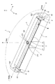
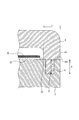
- the figure which shows the antenna apparatus of embodiment Sectional drawing which shows a groove part and a nail
- An antenna device 1 according to this embodiment shown in FIG. 1 is an antenna device used for a millimeter wave radar or the like for monitoring the periphery of a vehicle, for example.
- the millimeter wave radar recognizes a target existing around the vehicle by transmitting an electromagnetic wave having a predetermined frequency f0 (hereinafter referred to as a radar wave) and receiving a reflected wave of the radar wave from the target.
- the antenna device 1 includes an antenna unit 2, a case 3, and a radome 4.
- the antenna unit 2 includes a patch antenna 21, a conductor plate 22, and a dielectric substrate 23.
- the dielectric substrate 23 has a rectangular shape, the patch antenna 21 is formed on one surface of the dielectric substrate 23, and the other surface is mounted on the antenna mounting surface of the case 3.
- the surface of the dielectric substrate 23 on which the patch antenna 21 is formed is referred to as an antenna formation surface.
- the patch antenna 21 includes a radiating element 211 made of a conductor formed in a square shape, a microstrip line for feeding, and the like (not shown).
- a region where the patch antenna 21 (radiating element 211) is formed is referred to as an antenna opening surface. In the following, as shown in FIG.
- the center portion of the antenna portion 2 (the center portion of the patch antenna 21) is set as the origin, and the axis passing through the origin and parallel to the long side of the dielectric substrate 23 is the x axis
- An explanation will be given by appropriately using an xyz three-dimensional coordinate axis, where the axis passing through the origin and parallel to the short side of the dielectric substrate 23 is the y axis, and the axis passing through the origin and perpendicular to the plate surface of the dielectric substrate 23 is the z axis.
- the power feeding microstrip line is for feeding power to the patch antenna 21 (radiating element 211).
- the radiating element 211 is arranged so that one set of opposing sides is parallel to the x-axis direction and another set of opposing sides is parallel to the y-axis direction.
- the radiating element 211 has a side length of about ⁇ p / 2.
- the conductor plate 22 is a plate-like conductor formed on the antenna forming surface of the dielectric substrate 23.
- the conductor plate 22 is formed around the patch antenna 21 (radiating element 211) so as to be physically separated from the patch antenna 21 (radiating element 211).
- Patch antenna 21 operates with the x-axis direction as the main polarization direction.
- the patch antenna 21 is configured as an antenna that operates with the xz plane as a polarization plane (E plane) and can transmit and receive the polarization in the xz plane satisfactorily. That is, the directivity of the patch antenna 21 extends in the z-axis direction, which is the normal direction of the antenna opening surface, and as an example, has a target shape in the normal direction.
- the radome 4 is formed in an arch shape having a rectangular roof portion in which the x direction is the longitudinal direction and the y direction is the short direction.
- the radome 4 is formed in a shape that covers the antenna unit 2 by being attached to the case 3.
- the radome 4 is formed of a transmission material that is a material that transmits radar waves with low loss.
- the radome 4 has a thickness t that is m times the radar wave propagating inside the radome 4, that is, one half of the wavelength ⁇ g of the radar wave propagating in the transmitting material constituting the radome 4. It is formed to be a positive integer) value.
- the claw part 41 is formed in the surface 43 which contacts the case 3 in the both ends of the longitudinal direction of the radome 4 so that it may protrude from this surface.
- the surface of the radome 4 that contacts the case 3 is referred to as a radome side contact surface 43.
- claw part 41 is formed so that it may extend in a transversal direction. That is, the claw portion 41 is formed in a shape extending in the y direction that is a direction perpendicular to the xz plane that is the polarization plane (E plane) of the patch antenna 21. Furthermore, the nail
- the case 3 is formed in a substantially rectangular parallelepiped with the x direction as the long direction and the y direction as the short direction. Case 3 is formed of a conductor.
- the antenna unit 2 and the radome 4 are mounted on a mounting surface 32 that is a predetermined surface of the case 3.
- the groove part 31 is formed in the surface which contacts the radome 4 in the both ends of a longitudinal direction among the mounting surfaces 32 of the case 3.
- the surface of the mounting surface 32 on which the groove portion 31 is formed is referred to as a groove portion forming surface 322.
- the surface of the mounting surface 32 on which the patch antenna 21 is mounted is defined as the antenna installation surface 321, and the distance between the antenna installation surface 321 and the groove forming surface 322 in the normal direction of the opening surface of the patch antenna 21, that is, the z direction, is Are formed to be equal to or smaller than a predetermined interval.
- the predetermined interval may be, for example, the wavelength ⁇ 0 in free space corresponding to the radar wave frequency f0.
- the antenna installation surface 321 and the groove forming surface 322 are formed to be the same surface (mounting surface 32) so that the predetermined interval is zero.
- the groove 31 is formed to extend in the short direction of the case 3. That is, the groove 31 is formed in a shape extending in the y direction, which is a direction perpendicular to the xz plane that is the polarization plane of the patch antenna 21, on the mounting surface 32 (groove forming surface 322).
- the groove 31 is n times the wavelength of the radar propagating through the groove 31 in a direction having a predetermined angle with respect to the normal direction (z direction) of the opening surface of the patch antenna 21 (where n is It is formed to have a depth that is a positive integer).
- the normal direction of the opening surface of the patch antenna 21 and the normal direction of the mounting surface 32 of the case 3 are both equal to the z direction, and the groove portion 31 has a depth in the z direction. ing.
- the groove portion 31 is formed so as to engage the claw portion 41 included in the radome 4 in a state where the radome 4 is mounted on the mounting surface 32 of the case 3.
- the groove portion 31 is n times 1 of 2 of the wavelength ⁇ g of the radar wave propagating in the transmission material constituting the claw portion 41 engaged with the groove portion 31 in the normal direction (z direction) of the opening surface of the patch antenna 21. (Where n is a positive integer).
- the groove part 31 is formed so that the claw part 41 formed in the radome 4 may be engaged as described above.
- the radar wave R transmitted from the patch antenna 21 propagates through a first free space F ⁇ b> 1 that is a space between the patch antenna 21 and the radome 4.
- a part of the radar wave R that has passed through the first boundary surface L1 has a second boundary surface L2 that is a boundary surface between the radome 4 and the second free space F2 that is outside the antenna device 1.
- the reflected wave B is reflected, and the remainder is transmitted as a radar transmission wave T to the second free space F2.
- the second reflected wave B reflected by the second boundary surface L2 passes through the first boundary surface L1 and enters the first free space F1.
- the first reflected wave A by the first boundary surface L1 has a phase difference of ⁇ (rad) with respect to the radar wave R. This is because the refractive index of the radome 4 is larger than the refractive index of the first free space F1.
- the second reflected wave B by the second boundary surface L2 has the same phase as the radar wave R.
- the refractive index of the radome 4 is smaller than the refractive index of the second free space F2, so that no phase difference occurs during reflection.
- the path length in the state of reciprocating the radome 4 having the thickness t of ⁇ g / 2 is one wavelength ( ⁇ g)
- the phase difference between the first reflected wave A and the second reflected wave B is ⁇ (rad), that is, they are in antiphase, they act so as to cancel each other. That is, the composite reflected wave C in the first free space F1 is suppressed. In other words, the attenuation of the radar transmission wave T propagating to the second free space F2 is suppressed. Thereby, the disturbance of the directivity of the antenna apparatus 1 is suppressed.
- the radar wave S propagating through the radome 4 is transmitted through the second boundary surface L2 and propagates to the second free space F2, the radar wave propagating to the second free space F2 is This is a wave obtained by synthesizing the direct radar wave D propagating directly through the radome 4 and the radar wave E passing through the claw part 41 engaged with the groove 31.
- the phase of the radar wave E passing through the claw portion 41 is directly in phase with the radar wave D.
- the path length in the state of reciprocating the claw portion 41 engaged with the groove portion 31 having the depth d of ⁇ g / 2 is one wavelength ( ⁇ g), and no phase difference occurs directly with respect to the radar wave D. .
- claw part 41 (groove part 31) is suppressed, and attenuation
- the radome 4 is formed to have a thickness t that suppresses attenuation of radar waves propagating through the radome 4, and is attached to the case 3 by engaging the claw portion 41 with the groove portion 31. Since the case 3 is formed to a depth d that does not cause a phase difference caused by reciprocating the groove 31, unnecessary waves generated in the groove 31 are suppressed. Therefore, in the antenna device 1, the directivity disturbance as the antenna device 1 can be suppressed with the radome 4 provided.
- FIG. 5 is a diagram illustrating an example of directivity of the antenna device 1.
- the depth d of the groove 31 is set to one half of the wavelength of the radar wave propagating through the groove 31, the directivity is almost constant over a wide detection angle range, that is, the directivity. It can be confirmed that there is little disturbance.
- FIG. 7 An example of the directivity of the antenna device 9 as shown in FIG. 6 is shown in FIG. 7 as a comparative example.
- the antenna device 9 of the comparative example has a configuration in which the groove 3 is not provided in the case 3 as in this embodiment (a configuration in which the claw portion 41 is not provided), and the thickness t of the radome 4 is ⁇ g / 2 is formed. It can be confirmed that the antenna device 9 has almost constant directivity in the wide detection angle range (the directivity is less disturbed).
- the thickness t of the radome 4 and the depth d of the groove 31 are both one-half ( ⁇ g / 2) of the wavelength of the radar wave propagating through them, and therefore unwanted waves are generated. It is possible to suppress the disturbance of directivity of the antenna device 1.
- the radar wave is transmitted from the patch antenna 21 via the radome 4 .
- the same effect can be obtained when the radar wave is received from the outside of the antenna device 1 via the radome 4. Played.
- the groove 31 is formed so as to extend in a direction perpendicular to the polarization plane (xz plane) which is a predetermined plane including the normal direction (z direction) of the aperture plane of the patch antenna 21.
- production of the unnecessary wave in the groove part 31 can be effectively suppressed about the electromagnetic wave (E wave) in a polarization plane.
- E wave electromagnetic wave
- the [3C] radome 4 includes a claw portion 41 that is a convex portion that engages with the groove portion 31 provided in the case 3. Thereby, the radome 4 can be more stably fixed to the case 3.
- the antenna installation surface 321 and the groove forming surface 322 are configured to be the same surface (mounting surface 32). Thereby, especially in the range where the detection angle is large, the disturbance of the directivity of the patch antenna 21 can be suppressed.
- the antenna portion 2 and the patch antenna 21 correspond to an example of an antenna
- the claw portion 41 corresponds to an example of a convex portion.
- the groove 31 of the case 3 is formed so as to extend in the short direction (y direction) of the case 3, but is not limited thereto.
- a plurality of groove portions 31 may be formed at predetermined intervals in the short direction.
- the direction in which the groove 31 is formed and the direction in which the groove 31 is arranged at a predetermined interval are not limited to the short direction of the case 3 and may be any direction.
- it is desirable that the lateral direction of the case 3 is the direction perpendicular to the polarization plane (xz plane).
- the claw portion 41 is formed on the radome 4 so as to engage with the groove portion 31, but this is not restrictive.
- a configuration in which the claw portion 41 is not formed on the radome 4 may be employed.
- the depth d of the groove 31 may be n times the value of one half of the wavelength of the radar wave propagating in the adhesive instead of the transmitting material forming the claw portion 41.
- the square radiating element 211 of the patch antenna 21 is formed with a side length of about ⁇ p / 2, but the invention is not limited to this.
- the length of about ⁇ p / 2 is an example, and an optimal length may be set depending on various factors such as the shape and size of the case 3, for example.
- the patch antenna 21 functions as a transmission / reception antenna, but is not limited thereto.
- the patch antenna 21 may function as a transmission antenna or may function as a reception antenna.
Landscapes
- Engineering & Computer Science (AREA)
- Computer Security & Cryptography (AREA)
- Radar, Positioning & Navigation (AREA)
- Remote Sensing (AREA)
- Details Of Aerials (AREA)
- Support Of Aerials (AREA)
Abstract
アンテナ装置は、予め定められた周波数の電磁波の送信または受信のうち少なくとも一方を行うアンテナ(2、21)と、所定の面である搭載面(32)に前記アンテナを搭載するケース(3)と前記電磁波を透過させる材料で構成され、前記アンテナを覆うように前記搭載面に搭載されるレドーム(4)を有する。前記搭載面には溝部(31)が形成される。前記レドームは、内部を伝搬する前記電磁波の波長の2分の1をm倍(但しmは正の整数)した厚さを有する。前記溝部は、前記アンテナの開口面の法線方向に対して所定の角度を有する方向において、溝部を伝搬する前記電磁波の波長の2分の1をn倍(但しnは正の整数)した深さを有するように形成されている。
Description
本開示は、アンテナ装置に関し、詳しくはアンテナ装置としての指向性の乱れを抑制する技術に関する。
従来、アンテナ本体を外部から保護するためのレドームを備えるアンテナ装置が知られている。但し、レドームを備えることにより、アンテナ装置としての指向性に乱れが生じることがある。たとえば、特開2006-140956号公報では、レドームを備えるアンテナ装置において、レドームの厚さ、及びアンテナ本体とレドームとの間隔を調整することにより、アンテナ装置としての指向性の乱れを抑制する技術が記載されている。
アンテナ本体がアンテナケースに保持され、このアンテナ本体を覆うようにアンテナケースにレドームが設置される上記のような装置では、レドームをアンテナケースに固定するために、アンテナケースに溝を設け、この溝に、レドームに設けられたリブが掛合されるよう構成されていることがある。
このような掛合部では、アンテナ本体の指向性に乱れを生じさせる不要波が生じるため、問題となる。
本開示は、上記問題に鑑みてなされたものであり、レドームを備えるアンテナ装置において、指向性の乱れを抑制する技術を提供する。
本開示は、上記問題に鑑みてなされたものであり、レドームを備えるアンテナ装置において、指向性の乱れを抑制する技術を提供する。
本開示の一側面は、アンテナ装置であって、アンテナと、ケースと、レドームと、溝部とを備える。
アンテナは、予め定められた周波数の電磁波の送信または受信のうち少なくとも一方を行う。ケースは、所定の面である搭載面にアンテナを搭載する。レドームは、電磁波を透過させる材料で構成され、アンテナを覆うようにケースの搭載面に搭載される。溝部は、ケースにおける搭載面に形成される。
アンテナは、予め定められた周波数の電磁波の送信または受信のうち少なくとも一方を行う。ケースは、所定の面である搭載面にアンテナを搭載する。レドームは、電磁波を透過させる材料で構成され、アンテナを覆うようにケースの搭載面に搭載される。溝部は、ケースにおける搭載面に形成される。
ここで特に、レドームは、内部を伝搬する電磁波の波長の2分の1をm倍(但しmは正の整数)した厚さを有する。更に、溝部は、アンテナの開口面の法線方向に対して所定の角度を有する方向において、溝部を伝搬する電磁波の波長の2分の1をn倍(但しnは正の整数)した深さを有するように形成されている。
このようなアンテナ装置によれば、溝部の深さが該溝部を伝搬する電磁波の波長の2分の1をn倍した値であるため、溝部の往復に要した電磁波の経路長は、電磁波の1波長の正の整数倍となる。すなわち、溝部を往復することによる位相のずれが生じないため、溝部における不要波が抑制される。したがって、本開示のアンテナ装置では、レドームを備えた状態で、アンテナ装置としての指向性の乱れを抑制することができる。ここでは、アンテナからレドームを介して電磁波が送信される場合について説明したが、アンテナ装置外部からレドームを介して電磁波が受信される場合も同様の効果が奏される。
なお、特許請求の範囲に記載した括弧内の符号は、一つの態様として後述する実施形態に記載の具体的手段との対応関係を示すものであって、本開示の技術的範囲を限定するものではない。
添付図面において:
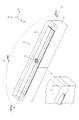
実施形態のアンテナ装置を示す図。
溝部及び爪部を示す断面図。
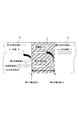
レドームを伝搬するレーダ波について説明する図。
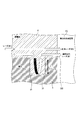
溝部を伝搬するレーダ波について説明する図。
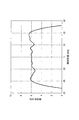
実施形態のアンテナ装置の指向性の一例を示す図。
比較例としてのアンテナ装置を示す図。
比較例としてのアンテナ装置の指向性の一例を示す図。
以下、本開示が適用された実施形態について、図面を用いて説明する。
[構成]
図1に示す本実施形態のアンテナ装置1は、例えば車両の周辺を監視するミリ波レーダ等に用いられるアンテナ装置である。ミリ波レーダは、予め定められた周波数f0の電磁波(以下、レーダ波という)を送信し、物標からのレーダ波の反射波を受信することで、車両の周囲に存在する物標を認識するものである。アンテナ装置1は、アンテナ部2と、ケース3と、レドーム4とを備える。
[構成]
図1に示す本実施形態のアンテナ装置1は、例えば車両の周辺を監視するミリ波レーダ等に用いられるアンテナ装置である。ミリ波レーダは、予め定められた周波数f0の電磁波(以下、レーダ波という)を送信し、物標からのレーダ波の反射波を受信することで、車両の周囲に存在する物標を認識するものである。アンテナ装置1は、アンテナ部2と、ケース3と、レドーム4とを備える。
アンテナ部2は、パッチアンテナ21と導体板22と誘電体基板23とを備える。誘電体基板23は長方形状であり、該誘電体基板23の一方の面にはパッチアンテナ21が形成され、他方の面はケース3のアンテナ搭載面に搭載されている。以下では、誘電体基板23の面のうち、パッチアンテナ21が形成されている面をアンテナ形成面という。
パッチアンテナ21は、正方形状に形成された導体からなる放射素子211、給電用のマイクロストリップライン等(図示せず)を備える。以下では、パッチアンテナ21(放射素子211)が形成されている領域をアンテナ開口面というものとする。また、以下では、図1に示すように、アンテナ部2の中心部(パッチアンテナ21の中心部)を原点として、その原点を通り且つ誘電体基板23の長辺に平行な軸をx軸、原点を通り且つ誘電体基板23の短辺に平行な軸をy軸、原点を通り且つ誘電体基板23の板面に垂直な軸をz軸とする、xyz三次元座標軸を適宜用いて説明する。
給電用のマイクロストリップラインは、パッチアンテナ21(放射素子211)への給電を行うためのものである。
放射素子211は、対向する一組の辺がx軸方向に平行となるよう、且つ対向するもう一組の辺がy軸方向に平行となるように配置されている。放射素子211は、一例として、一辺の長さが、約λp/2に形成されている。λpは、予め定められたレーダ波の周波数f0に対応した波長(ただし誘電体内波長)であり、自由空間波長をλ0、誘電体基板23の比誘電率をεpとすると、λp=λ0/√εpで表される。
放射素子211は、対向する一組の辺がx軸方向に平行となるよう、且つ対向するもう一組の辺がy軸方向に平行となるように配置されている。放射素子211は、一例として、一辺の長さが、約λp/2に形成されている。λpは、予め定められたレーダ波の周波数f0に対応した波長(ただし誘電体内波長)であり、自由空間波長をλ0、誘電体基板23の比誘電率をεpとすると、λp=λ0/√εpで表される。
導体板22は、誘電体基板23のアンテナ形成面に形成されている板状の導体である。導体板22は、パッチアンテナ21(放射素子211)の周囲に、パッチアンテナ21(放射素子211)とは物理的に離間するように形成されている。
パッチアンテナ21は、x軸方向を主偏波方向として作動する。パッチアンテナ21は、xz面を偏波面(E面)として作動し、このxz面の偏波を良好に送受信可能なアンテナとして構成されている。つまり、パッチアンテナ21の指向性は、アンテナ開口面の法線方向であるz軸方向に延びており、一例としてこの法線方向に対象な形状となっている。
レドーム4は、x方向を長手方向としy方向を短手方向とする長方形状の屋根部を備えるアーチ状に形成されている。レドーム4は、ケース3に取り付けられることにより、アンテナ部2を覆う形状に形成されている。レドーム4は、レーダ波を低損失で透過させる材料である透過材で形成されている。レドーム4は、その厚さtが、レドーム4の内部を伝搬するレーダ波、すなわちレドーム4を構成する透過材中を伝搬するレーダ波の波長λgの2分の1をm倍(但し、mは正の整数)した値となるように形成されている。本実施形態では、m=1としたときの値、すなわち、λg/2の厚さtを有するように、レドーム4が形成されている(t=λg/2)。ここで、透過材中を伝播するレーダ波の波長λgは、予め定められたレーダ波の周波数f0に対応した自由空間における波長をλ0とし、透過材の比誘電率をεrとすると、λg=λ0/√εrで表される値である。
レドーム4の長手方向の両端部における、ケース3と接触する面43には、この面から突出するように爪部41が形成されている。以下では、レドーム4においてケース3と接触する面をレドーム側接触面43という。爪部41は、短手方向に延びるように形成されている。すなわち、爪部41は、パッチアンテナ21の偏波面(E面)であるxz面に垂直な方向であるy方向に延びる形状に形成されている。さらに、爪部41は、後述するケース3に設けられた溝部31に掛合される形状に形成されている。一例として本実施形態では、爪部41は、その長さが溝部31の深さdと同様となるように形成されている。
ケース3は、x方向を長手方向としy方向を短手方向とする略直方体に形成されている。ケース3は、導体により形成されている。ケース3の所定の面である搭載面32には、アンテナ部2とレドーム4とが搭載されている。
ケース3の搭載面32のうち、長手方向の両端部におけるレドーム4と接触する面には、溝部31が形成されている。以下では、搭載面32のうち溝部31が形成されている面を溝部形成面322という。搭載面32のうちパッチアンテナ21が搭載されている面をアンテナ設置面321として、パッチアンテナ21の開口面の法線方向、すなわちz方向における、アンテナ設置面321と溝部形成面322との間隔は、所定の間隔以下となるように形成されている。所定の間隔は、例えば、レーダ波の周波数f0に対応した自由空間における波長λ0であってもよい。本実施形態では、所定の間隔が0となるように、すなわち、アンテナ設置面321と溝部形成面322とが同一の面(搭載面32)となるように形成されている。
溝部31は、ケース3の短手方向に延びるように形成されている。すなわち、溝部31は、搭載面32(溝部形成面322)において、パッチアンテナ21の偏波面であるxz面に垂直な方向であるy方向に延びる形状に形成されている。
溝部31は、パッチアンテナ21の開口面の法線方向(z方向)に対して所定の角度を有する方向において、溝部31を伝搬するレーダの波長の2分の1をn倍(但し、nは正の整数)した深さを有するように形成されている。本実施形態では、パッチアンテナ21の開口面の法線方向とケース3の搭載面32の法線方向とは等しく共にz方向となっており、溝部31はz方向に深さを有する形状となっている。
図2に示すように、溝部31は、ケース3の搭載面32にレドーム4が搭載された状態で、レドーム4が備える爪部41を掛合するように形成されている。溝部31は、パッチアンテナ21の開口面の法線方向(z方向)において、溝部31に掛合される爪部41を構成する透過材中を伝搬するレーダ波の波長λgの2の1をn倍(但し、nは正の整数)した値となるように形成されている。本実施形態では、n=1としたときの値、すなわち、λg/2の深さdを有するように溝部31が形成されている(d=λg/2)。
溝部31は、前述のようにレドーム4に形成された爪部41が掛合するように形成されている。このため、本実施形態では、爪部41は、その長さhがλg/2となるように形成されている(h=λg/2)。
[作用]
レーダ波がパッチアンテナ21からレドーム4を経てアンテナ装置1外部へ送信される場合を例にとって、アンテナ装置1の作用を説明する。
レーダ波がパッチアンテナ21からレドーム4を経てアンテナ装置1外部へ送信される場合を例にとって、アンテナ装置1の作用を説明する。
はじめに、レドーム4の作用について説明する。図3に示すように、パッチアンテナ21から送信されたレーダ波Rは、パッチアンテナ21とレドーム4との間の空間である第1の自由空間F1を伝搬する。
レーダ波Rの一部は、比誘電率εrが1(比誘電率εr=1)である第1の自由空間F1と、比誘電率εrが1より大きい(比誘電率εr>1)レドーム4との境界面である第1の境界面L1において、第1の反射波Aとして反射され、残りは第1の境界面L1を透過する。
第1の境界面L1を透過したレーダ波Rの一部は、レドーム4とアンテナ装置1の外部である第2の自由空間F2との境界面である第2の境界面L2において、第2の反射波Bとして反射され、残りはレーダ送信波Tとして第2の自由空間F2へ送信される。第2の境界面L2で反射された第2の反射波Bは、第1の境界面L1を透過し、第1の自由空間F1に入射される。
屈折率の小さい媒質から大きい媒質へ伝搬する電磁波は、媒質の境界面で反射される際にその反射波にπ(rad)の位相差が生じ、屈折率の大きい媒質から小さい媒質へ伝搬する電磁波は、媒質の境界面で反射される際に位相差が生じないこと、が周知である。屈折率は媒質の比誘電率の1/2乗に比例する値である。
ここで、第1の自由空間F1において、第1の境界面L1による第1の反射波Aは、レーダ波Rに対する位相差がπ(rad)である。レドーム4の屈折率は、第1の自由空間F1の屈折率より大きいためである。
一方、第1の自由空間F1において、第2の境界面L2による第2の反射波Bは、レーダ波Rと同位相となる。レドーム4の屈折率は第2の自由空間F2の屈折率より小さいため、反射の際に位相差が生じないからである。且つ、厚さtがλg/2であるレドーム4を往復した状態での経路長は1波長分(λg)となるため、レドーム4を往復する際にレーダ波Rに対する位相差が生じないからである。
よって、第1の反射波Aと第2の反射波Bとの位相差がπ(rad)である、すなわち逆位相であるため、これらは互いに打ち消し合うように作用する。すなわち、第1の自由空間F1における合成反射波Cが抑制される。換言すれば、第2の自由空間F2へ伝搬するレーダ送信波Tの減衰が抑制される。これにより、アンテナ装置1の指向性の乱れが抑制される。
次に、ケース3に形成された溝部31の作用について説明する。図4に示すように、レドーム4を伝搬するレーダ波Sが第2の境界面L2を透過して第2の自由空間F2へ伝搬する場合、第2の自由空間F2へ伝搬するレーダ波は、レドーム4を直接伝搬する直接レーダ波Dと、溝部31に掛合された爪部41を経由するレーダ波Eとを合成した波となる。
ここで爪部41を経由するレーダ波Eの位相は、直接レーダ波Dと同位相となる。深さdがλg/2である溝部31に掛合された爪部41を往復した状態での経路長は1波長分(λg)となり、直接レーダ波Dに対して位相差が生じないからである。これにより、爪部41(溝部31)において不要波が生じることが抑制され、直接レーダ波Dの減衰が抑制される。すなわち、アンテナ装置1の指向性の乱れが抑制される。
[効果]
以上詳述した実施形態によれば、以下の効果が得られる。
[3A]レドーム4は、レドーム4を伝搬するレーダ波の減衰を抑制する厚さtを有するように形成されており、爪部41が溝部31に掛合されることによってケース3に取り付けられる。ケース3は、溝部31を往復することによる位相差が生じないような深さdに形成されているため、溝部31において生じる不要波が抑制される。したがって、アンテナ装置1では、レドーム4を備えた状態で、アンテナ装置1としての指向性の乱れを抑制することができる。
以上詳述した実施形態によれば、以下の効果が得られる。
[3A]レドーム4は、レドーム4を伝搬するレーダ波の減衰を抑制する厚さtを有するように形成されており、爪部41が溝部31に掛合されることによってケース3に取り付けられる。ケース3は、溝部31を往復することによる位相差が生じないような深さdに形成されているため、溝部31において生じる不要波が抑制される。したがって、アンテナ装置1では、レドーム4を備えた状態で、アンテナ装置1としての指向性の乱れを抑制することができる。
ここで、図5は、アンテナ装置1の指向性の一例を示す図である。溝部31の深さdを溝部31を伝搬するレーダ波の波長の2分の1とした場合は、そうでない場合と比べて、広い検知角度範囲において指向性がほぼ一定であること、すなわち指向性に乱れが少ないことが確認できる。
なお、比較例として図6に示すようなアンテナ装置9の指向性の一例を図7に示す。比較例のアンテナ装置9は、ケース3に本実施形態のような溝部31を備えない構成(爪部41を備えない構成)であり、レドーム4の厚さtは本実施形態と同様にλg/2に形成されている。アンテナ装置9は、広い検知角度範囲において指向性がほぼ一定である(指向性に乱れが少ない)ことが確認できる。
つまり、図5及び図7から明らかであるように、レドーム4をケース3に取り付けるためにケース3に溝部31を備える場合、溝部31において不要波が生じるため、アンテナ装置の指向性に乱れが生じている。
本実施形態のアンテナ装置1では、レドーム4の厚さt及び溝部31の深さdが共に、これらを伝搬するレーダ波の波長の2分の1(λg/2)であるため、不要波を抑制することができ、アンテナ装置1の指向性の乱れを抑制することができる。
なお、本実施形態では、パッチアンテナ21からレドーム4を介してレーダ波が送信される場合について説明したが、アンテナ装置1外部からレドーム4を介してレーダ波が受信される場合も同様の効果が奏される。
[3B]パッチアンテナ21の開口面の法線方向(z方向)を含む所定の面である偏波面(xz面)に対して垂直となる方向に延びるように、溝部31が形成されている。これにより、偏波面における電波(E波)について、溝部31における不要波の発生を効果的に抑制することができる。特に、検知角度が大きい範囲における指向性の乱れを抑制することができる。
[3C]レドーム4は、ケース3に設けられた溝部31と掛合する凸部である爪部41を備える。これにより、ケース3にレドーム4をより安定して固定することができる。
[3D]アンテナ設置面321と溝部形成面322とが同一面(搭載面32)となるように構成されている。これにより、特に検知角度の大きい範囲において、パッチアンテナ21の指向性の乱れを抑制することができる。
なお、本実施形態では、アンテナ部2及びパッチアンテナ21がアンテナの一例に相当し、爪部41が凸部の一例に相当する。
[他の実施形態]
以上、本開示の実施形態について説明したが、本開示は、上記実施形態に限定されることなく、種々の形態を採り得ることは言うまでもない。
[他の実施形態]
以上、本開示の実施形態について説明したが、本開示は、上記実施形態に限定されることなく、種々の形態を採り得ることは言うまでもない。
[4A]上記実施形態では、ケース3の溝部31は、ケース3の短手方向(y方向)に延びるように形成されていたが、これに限るものではない。例えば、短手方向に、所定間隔をあけて、複数の溝部31が形成されていてもよい。また、溝部31が延びるように形成される方向、及び溝部31が所定間隔をあけて並ぶ方向は、ケース3の短手方向に限らず、任意の方向としてもよい。ただし、上記実施形態のように、ケース3の短手方向、すなわち、偏波面(xz面)に垂直な方向であることが望ましい。
[4B]上記実施形態では、溝部31と掛合するようにレドーム4に爪部41が形成されていたが、これに限るものではない。例えば、レドーム4に爪部41が形成されていない構成であってもよい。この場合、例えば溝部31に接着材等を充填し、レドーム4をケース3に固定することが考えられる。この場合、溝部31の深さdは、爪部41を形成する透過材に代えて接着剤中を伝搬するレーダ波の波長の2分の1の値のn倍であればよい。
[4C]上記実施形態では、パッチアンテナ21の正方形状の放射素子211は、一辺の長さが約λp/2に形成されていたが、これに限るものではない。この約λp/2という長さは一例であり、例えばケース3の形状やサイズ等の種々の要因によって最適な長さを設定してよい。
[4D]上記実施形態では、パッチアンテナ21は送受信アンテナとして機能するものであったが、これに限るものではない。パッチアンテナ21は、送信アンテナとして機能するものであってもよく、または受信アンテナとして機能するものであってもよい。
[4E]上記実施形態における1つの構成要素が有する機能を複数の構成要素として分散させたり、複数の構成要素が有する機能を1つの構成要素に統合したりしてもよい。また、上記実施形態の構成の少なくとも一部を、同様の機能を有する公知の構成に置き換えてもよい。また、上記実施形態の構成の一部を、課題を解決できる限りにおいて省略してもよい。また、上記実施形態の構成の少なくとも一部を、他の上記実施形態の構成に対して付加、置換等してもよい。なお、特許請求の範囲に記載の文言から特定される技術思想に含まれるあらゆる態様が本開示の実施形態である。
1…アンテナ装置 2…アンテナ部 3…ケース 4…レドーム 21…パッチアンテナ 31…溝部 32…搭載面 321…アンテナ設置面 322…溝部形成面 41…爪部 43…レドーム側接触面。
Claims (7)
- 予め定められた周波数の電磁波の送信または受信のうち少なくとも一方を行うアンテナ(2、21)と、
搭載面(32)を所定の面に備え、前記アンテナを前記搭載面に搭載するケース(3)と、
前記電磁波を透過させる材料で構成され、前記アンテナを覆うように前記搭載面に搭載されるレドーム(4)と、
前記搭載面に形成された溝部(31)と、
を備え、
前記レドームは、内部を伝搬する前記電磁波の波長の2分の1をm倍(但しmは正の整数)した厚さを有し、
前記溝部は、前記アンテナの開口面の法線方向に対して所定の角度を有する方向において、溝部を伝搬する前記電磁波の波長の2分の1をn倍(但しnは正の整数)した深さを有するように形成されていること
を特徴とするアンテナ装置。 - 請求項1に記載のアンテナ装置であって、
前記溝部は、前記アンテナの開口面の法線方向を含む所定の面である偏波面に対して垂直な方向に延びるように形成されていること
を特徴とするアンテナ装置。 - 請求項1に記載のアンテナ装置であって、
前記レドームは、前記溝部に掛合される凸部(41)を備えること
を特徴とするアンテナ装置。 - 請求項2に記載のアンテナ装置であって、
前記レドームは、前記溝部に掛合される凸部(41)を備えること
を特徴とするアンテナ装置。 - 請求項1に記載のアンテナ装置であって、
前記搭載面は、前記アンテナが搭載されるアンテナ設置面(321)と、前記溝部が形成される溝部形成面(322)を有し、前記アンテナの前記開口面の法線方向における、前記アンテナ設置面と前記溝部形成面との間隔が、所定の間隔以下であることを特徴とするアンテナ装置。 - 請求項2に記載のアンテナ装置であって、
前記搭載面は、前記アンテナが搭載されるアンテナ設置面(321)と、前記溝部が形成される溝部形成面(322)を有し、前記アンテナの前記開口面の法線方向における、前記アンテナ設置面と前記溝部形成面との間隔が、所定の間隔以下であることを特徴とするアンテナ装置。 - 請求項3に記載のアンテナ装置であって、
前記搭載面は、前記アンテナが搭載されるアンテナ設置面(321)と、前記溝部が形成される溝部形成面(322)を有し、前記アンテナの前記開口面の法線方向における、前記アンテナ設置面と前記溝部形成面との間隔が、所定の間隔以下であることを特徴とするアンテナ装置。
Priority Applications (1)
| Application Number | Priority Date | Filing Date | Title |
|---|---|---|---|
| US15/322,850 US10038236B2 (en) | 2014-07-01 | 2015-07-01 | Antenna apparatus provided with radome |
Applications Claiming Priority (2)
| Application Number | Priority Date | Filing Date | Title |
|---|---|---|---|
| JP2014-135988 | 2014-07-01 | ||
| JP2014135988A JP6235424B2 (ja) | 2014-07-01 | 2014-07-01 | アンテナ装置 |
Publications (1)
| Publication Number | Publication Date |
|---|---|
| WO2016002832A1 true WO2016002832A1 (ja) | 2016-01-07 |
Family
ID=55019362
Family Applications (1)
| Application Number | Title | Priority Date | Filing Date |
|---|---|---|---|
| PCT/JP2015/068956 Ceased WO2016002832A1 (ja) | 2014-07-01 | 2015-07-01 | レドームを備えるアンテナ装置 |
Country Status (3)
| Country | Link |
|---|---|
| US (1) | US10038236B2 (ja) |
| JP (1) | JP6235424B2 (ja) |
| WO (1) | WO2016002832A1 (ja) |
Cited By (2)
| Publication number | Priority date | Publication date | Assignee | Title |
|---|---|---|---|---|
| WO2020262071A1 (ja) * | 2019-06-28 | 2020-12-30 | 株式会社デンソー | レーダ装置 |
| WO2022186385A1 (ja) | 2021-03-04 | 2022-09-09 | 大日本印刷株式会社 | 周波数選択反射板および反射構造体 |
Families Citing this family (4)
| Publication number | Priority date | Publication date | Assignee | Title |
|---|---|---|---|---|
| US10389019B2 (en) * | 2016-12-17 | 2019-08-20 | Point Road Solutions, Llc | Methods and systems for wet radome attenuation mitigation in phased-array antennae applications and networked use of such applications |
| WO2021125047A1 (ja) | 2019-12-20 | 2021-06-24 | スタンレー電気株式会社 | 発光ユニット及びランプ装置 |
| CN117296201A (zh) * | 2021-05-19 | 2023-12-26 | 灏讯有限公司 | 用于汽车雷达应用的天线装置 |
| CN113721081B (zh) * | 2021-09-27 | 2024-03-15 | 国家无线电监测中心检测中心 | 一种天线罩的最佳厚度的测量方法和系统 |
Citations (3)
| Publication number | Priority date | Publication date | Assignee | Title |
|---|---|---|---|---|
| JP2007116217A (ja) * | 2005-10-18 | 2007-05-10 | Hitachi Ltd | ミリ波レーダ装置およびそれを用いたミリ波レーダシステム |
| JP2012215455A (ja) * | 2011-03-31 | 2012-11-08 | Furukawa Electric Co Ltd:The | 広覆域レーダ装置 |
| JP2014020846A (ja) * | 2012-07-13 | 2014-02-03 | Denso Corp | レーダ装置 |
Family Cites Families (8)
| Publication number | Priority date | Publication date | Assignee | Title |
|---|---|---|---|---|
| US2472089A (en) * | 1945-04-03 | 1949-06-07 | Linn S Brennan | Coil winder |
| US2896010A (en) * | 1956-07-05 | 1959-07-21 | Milton Herman | Automobile antenna |
| US3544848A (en) * | 1968-10-02 | 1970-12-01 | Motorola Inc | Housing for electronic equipment with rotatable circuit board means |
| JPS6114505U (ja) * | 1984-06-26 | 1986-01-28 | 三菱電機株式会社 | ホ−ンアンテナ装置 |
| US5648726A (en) * | 1995-04-21 | 1997-07-15 | Pacific Scientific Company | Remotely accessible electrical fault detection |
| JP4065268B2 (ja) | 2004-11-15 | 2008-03-19 | アンリツ株式会社 | 車載用アンテナ |
| US7889151B1 (en) * | 2007-11-08 | 2011-02-15 | The United States Of America As Represented By The Secretary Of The Navy | Passive wide-band low-elevation nulling antenna |
| WO2013090783A1 (en) * | 2011-12-14 | 2013-06-20 | Laird Technologies, Inc. | Multiband mimo antenna assemblies operable with lte frequencies |
-
2014
- 2014-07-01 JP JP2014135988A patent/JP6235424B2/ja active Active
-
2015
- 2015-07-01 US US15/322,850 patent/US10038236B2/en active Active
- 2015-07-01 WO PCT/JP2015/068956 patent/WO2016002832A1/ja not_active Ceased
Patent Citations (3)
| Publication number | Priority date | Publication date | Assignee | Title |
|---|---|---|---|---|
| JP2007116217A (ja) * | 2005-10-18 | 2007-05-10 | Hitachi Ltd | ミリ波レーダ装置およびそれを用いたミリ波レーダシステム |
| JP2012215455A (ja) * | 2011-03-31 | 2012-11-08 | Furukawa Electric Co Ltd:The | 広覆域レーダ装置 |
| JP2014020846A (ja) * | 2012-07-13 | 2014-02-03 | Denso Corp | レーダ装置 |
Cited By (3)
| Publication number | Priority date | Publication date | Assignee | Title |
|---|---|---|---|---|
| WO2020262071A1 (ja) * | 2019-06-28 | 2020-12-30 | 株式会社デンソー | レーダ装置 |
| CN114096878A (zh) * | 2019-06-28 | 2022-02-25 | 株式会社电装 | 雷达装置 |
| WO2022186385A1 (ja) | 2021-03-04 | 2022-09-09 | 大日本印刷株式会社 | 周波数選択反射板および反射構造体 |
Also Published As
| Publication number | Publication date |
|---|---|
| US10038236B2 (en) | 2018-07-31 |
| JP6235424B2 (ja) | 2017-11-22 |
| JP2016015575A (ja) | 2016-01-28 |
| US20170155190A1 (en) | 2017-06-01 |
Similar Documents
| Publication | Publication Date | Title |
|---|---|---|
| JP6235424B2 (ja) | アンテナ装置 | |
| CN106169652B (zh) | 天线装置、无线通信装置及雷达装置 | |
| EP2940907B1 (en) | Antenna system | |
| US9502760B2 (en) | Radar apparatus provided with radome | |
| CN104078766B (zh) | 天线设备和雷达设备 | |
| US8593369B2 (en) | Antenna assembly | |
| JP2016006411A (ja) | ミリ波用アンテナ及び車載用レーダ装置 | |
| US9445535B2 (en) | High-frequency module | |
| JPWO2008090846A1 (ja) | エンブレム | |
| KR20190058072A (ko) | 차량용 레이더 장치 | |
| JP7099861B2 (ja) | レーダ装置 | |
| US20240069155A1 (en) | Radar apparatus | |
| CN106249206B (zh) | 用于接收电磁波的天线设备和用于运行用于接收电磁波的天线设备的方法 | |
| JP2007235287A (ja) | 車載用電波レーダ装置 | |
| KR100446033B1 (ko) | 자동차윈드스크린의내측에평면안테나를장착하기위한안테나장치 | |
| US12300881B2 (en) | Radar device | |
| JP2012220418A (ja) | アンテナ装置およびレーダ装置 | |
| US9153866B2 (en) | Communication medium | |
| US20220278464A1 (en) | High-frequency device | |
| JP6160330B2 (ja) | レドーム | |
| KR20150055280A (ko) | 캐릭터 라인에 의해 발생되는 사이드 로브를 감쇄시키기 위한 구조 시스템 | |
| WO2016093235A1 (ja) | 反射波を打ち消し合う形状に形成されたレドームを備えた車載アンテナ装置及び車載レーダ装置 | |
| KR20100120847A (ko) | 다이버시티 효과를 적용한 마이크로파 탐지 안테나 |
Legal Events
| Date | Code | Title | Description |
|---|---|---|---|
| 121 | Ep: the epo has been informed by wipo that ep was designated in this application |
Ref document number: 15814738 Country of ref document: EP Kind code of ref document: A1 |
|
| WWE | Wipo information: entry into national phase |
Ref document number: 15322850 Country of ref document: US |
|
| NENP | Non-entry into the national phase |
Ref country code: DE |
|
| 122 | Ep: pct application non-entry in european phase |
Ref document number: 15814738 Country of ref document: EP Kind code of ref document: A1 |