WO2016002783A1 - コア片、及びリアクトル - Google Patents
コア片、及びリアクトル Download PDFInfo
- Publication number
- WO2016002783A1 WO2016002783A1 PCT/JP2015/068835 JP2015068835W WO2016002783A1 WO 2016002783 A1 WO2016002783 A1 WO 2016002783A1 JP 2015068835 W JP2015068835 W JP 2015068835W WO 2016002783 A1 WO2016002783 A1 WO 2016002783A1
- Authority
- WO
- WIPO (PCT)
- Prior art keywords
- resin
- core piece
- core
- reactor
- coil
- Prior art date
- Legal status (The legal status is an assumption and is not a legal conclusion. Google has not performed a legal analysis and makes no representation as to the accuracy of the status listed.)
- Ceased
Links
Images



Classifications
-
- H—ELECTRICITY
- H01—ELECTRIC ELEMENTS
- H01F—MAGNETS; INDUCTANCES; TRANSFORMERS; SELECTION OF MATERIALS FOR THEIR MAGNETIC PROPERTIES
- H01F27/00—Details of transformers or inductances, in general
- H01F27/24—Magnetic cores
-
- H—ELECTRICITY
- H01—ELECTRIC ELEMENTS
- H01F—MAGNETS; INDUCTANCES; TRANSFORMERS; SELECTION OF MATERIALS FOR THEIR MAGNETIC PROPERTIES
- H01F37/00—Fixed inductances not covered by group H01F17/00
Definitions
- the present invention relates to a reactor used for a core piece constituting a magnetic core provided in a magnetic component such as a reactor, a vehicle-mounted DC-DC converter mounted on a vehicle such as a hybrid vehicle, or a component of a power converter.
- the present invention relates to a core piece and a reactor that are excellent in bondability with a resin portion and also excellent in manufacturability.
- Patent Document 1 discloses a magnetic core formed in a ring shape by combining a coil formed by winding a winding in a spiral shape and a plurality of core pieces as a reactor used in a converter mounted on a vehicle such as a hybrid vehicle. The thing provided with is disclosed. Patent Document 1 discloses a resin that covers each core piece with an insulating coating layer (resin layer), covers a plurality of core pieces integrally with a resin layer, and covers an end face of the core piece arranged in the coil. The use of layers for gaps is disclosed.
- a core piece and a reactor that are excellent in bondability with a resin part and excellent in manufacturability are desired.
- ⁇ ⁇ ⁇ Coils for magnetic components such as reactors generate heat due to Joule heat when energized and do not generate heat when de-energized.
- the heat generation of the coil is large.
- the core piece disposed in the vicinity of the coil and the resin layer covering the core piece undergo thermal expansion and contraction due to the heat cycle caused by the coil.
- the core piece mainly composed of metal such as iron and the resin have different coefficients of thermal expansion, so that the resin layer may peel from the core piece due to thermal expansion and contraction. If the resin layer is peeled off, the function of the resin layer may not be sufficiently exhibited.
- the location where the resin layer is peeled from the core piece disposed in the coil may be a weak point of insulation with the coil, and the gap length provided between the core pieces may vary. Further, for example, when the resin layer is peeled off and the integration of the plurality of core pieces is insufficient, the resonance frequency before and after the peeling is changed, and there is a possibility that vibration and noise are increased as compared with those before the peeling.
- the present inventors make the bonding surface of the core piece with the resin portion uneven, specifically, forming a groove on the outer periphery of the core piece. Then, it was examined to increase the contact area with the resin part.
- the laser energy decreases from the groove opening toward the bottom, resulting in the groove 350 as shown in FIG.
- the cross-sectional shape can be U-shaped or V-shaped. That is, the inner space becomes narrower (the planar area becomes smaller) from the opening 350o of the groove 350 toward the bottom 350b, and the bottom 350b can be linear or dotted.
- the resin is not filled into every corner of the groove 350 depending on the type and viscosity of the resin, the resin filling condition, etc., and the effect of increasing the contact area with the resin portion by the groove 350 is sufficiently exhibited. There is a fear that it cannot be done.
- the resin may cover the opening 350 o with insufficient deaeration in the groove 350, and gas may remain in the groove 350. The gas is thermally expanded to push up the surrounding resin, and the unfilled portion of the resin in the groove 350 can be a starting point for peeling of the resin portion.
- a core piece according to one aspect of the present invention is a core piece constituting a magnetic core disposed inside and outside a coil formed by winding a winding, and a resin portion is bonded to at least a part of the outer periphery of the core piece.
- the region where the resin portion is joined includes a recess and a projection surrounding the periphery of the recess, and the recess has a planar shape that is similar to the opening and the opening. And a bottom portion.
- a reactor according to an aspect of the present invention includes a coil formed by winding a winding, a magnetic core including a plurality of core pieces including the core piece according to the aspect of the present invention, and an outer periphery of the plurality of core pieces. Among these, at least a resin portion joined to a region including the concave portion and the convex portion is provided.
- the above-mentioned core piece is excellent in bondability with the resin part and easily forms the resin part.
- Said reactor is excellent also in manufacturability besides being excellent in bondability with a resin part.
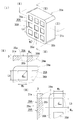
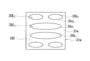
- FIG. It is explanatory drawing explaining the recessed part and convex part which the core piece of Embodiment 1 has, (I) is a schematic perspective view of a core piece, (II) includes a recessed part and a convex part about the core piece of (I). (II)-(II) A partial cross-sectional view and a partial plan view obtained by cutting the section along a cutting line.
- (III) is a section of the core piece of (I) including a recess and a projection (III)-(III) A partial sectional view and a partial plan view cut along a line are shown. It is explanatory drawing explaining an example (circular shape of the same magnitude
- FIG. It is explanatory drawing explaining an example (oval shape of the same magnitude
- FIG. It is explanatory drawing explaining an example (oval shape of a different magnitude
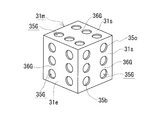
- FIG. It is explanatory drawing which shows the example which equips both the end surface and peripheral surface with a recessed part and a convex part about the core piece of Embodiment 2.
- FIG. It is a section explanatory view explaining a slot whose section shape is V shape.
- a core piece according to an aspect of the present invention is a core piece constituting a magnetic core disposed inside and outside a coil formed by winding a winding, and a resin is provided on at least a part of the outer periphery of the core piece.
- a region where the resin portion is bonded, and the region where the resin portion is bonded includes a concave portion and a convex portion surrounding the concave portion, and the concave portion has a shape similar to the opening portion and the opening portion.
- a flat bottom is a core piece constituting a magnetic core disposed inside and outside a coil formed by winding a winding, and a resin is provided on at least a part of the outer periphery of the core piece.
- a region where the resin portion is bonded, and the region where the resin portion is bonded includes a concave portion and a convex portion surrounding the concave portion, and the concave portion has a shape similar to the opening portion and the opening portion.
- a flat bottom is
- Similar and flat is as follows. A planar shape of the opening of the recessed portion is extracted along the peripheral edge forming the opening of the recessed portion, and an envelope circle including the extracted planar figure is taken. Along the diameter of the envelope circle, the depth of the recess is measured using a known measuring device such as a laser displacement meter, and the average is defined as the average depth of the recess. If the difference between each measured value on the diameter and the average depth is within 30% of the average depth, the recess is substantially uniform in depth and flat enough to be regarded as a flat bottom. It can be said that there is.
- the planar shape of the bottom is similar to the planar shape of the opening. Furthermore, it can be said that in such a recess, the planar area of the bottom sufficiently maintains the planar area of the opening (for example, 70% or more of the area of the opening is satisfied). Therefore, a case where the difference from the above average depth is within 30% of the average depth is defined as a similar shape and a planar shape. That is, in the above-described core piece, the case where the bottom of the concave portion has very fine irregularities is allowed.
- Said core piece is excellent in bondability with a resin part by providing a specific recessed part and a convex part in the area
- region where the resin part in said core piece is joined is uneven
- the said core piece is excellent in manufacturability of the core piece provided with a resin part because a recessed part is a specific shape, and contributes to the improvement of the manufacturability of a reactor by extension.
- the bottom of the concave portion is substantially flat, and the planar shape of the bottom and the planar shape of the opening are substantially equal. That is, when the recess is viewed in the depth direction, the planar area of the opening is generally maintained until reaching the bottom, and the inner space of the recess is substantially uniform in size from the opening to the bottom. Therefore, the above-described core piece having a specific recess is degassed and filled with resin when the resin portion is formed, as compared with the case where the groove 350 (FIG.
- an end surface orthogonal to the magnetic flux of the coil includes a plurality of the concave portions and the convex portions that divide the adjacent concave portions.
- the resin portion can be firmly joined to the end face.
- the resin part bonded to the end face can be used as a gap when the core piece of the above-described form is used for a magnetic component such as a reactor.
- variation in the gap length caused by the peeling of the resin part can be suppressed.
- the gap material can be omitted, the number of parts such as a reactor can be reduced. Therefore, the said form can contribute to maintenance of the gap length in a reactor etc. and improvement of manufacturability, such as a reactor.
- the core piece there may be mentioned a form in which the concave portion and the convex portion are provided on the circumferential surface parallel to the magnetic flux of the coil.
- the resin portion can be firmly joined to the peripheral surface. Therefore, when the core piece of the above form is used for a magnetic part such as a reactor, the resin part bonded to the peripheral surface ensures good insulation between the coil and the core piece for a long time, and the machine of the core piece Protection and protection from the environment.
- a reactor or the like includes a plurality of core pieces including the core piece of the above form and the resin part is integrally joined to the peripheral surface of the adjacent core piece, the resin part is firmly attached to the core piece of the above form. Therefore, the plurality of core pieces are firmly integrated by the resin portion.
- the adjacent core pieces are more firmly integrated by the resin portion.
- the core piece group integrated in this way can suppress deterioration in insulation performance and increase in vibration and noise due to peeling of the resin portion. Therefore, when used in a reactor or the like, the above configuration can contribute to ensuring insulation between the coil and the core piece and maintaining excellent vibration resistance over a long period of time.
- the core piece there may be mentioned a form that is a compacted body including metal particles and an insulating material interposed between the metal particles.
- a reactor according to one aspect of the present invention includes a plurality of core pieces including a coil formed by winding a winding and the core piece according to any one of (1) to (4) above.
- a magnetic core and a resin portion bonded to at least the region including the concave portion and the convex portion in the outer periphery of the plurality of core pieces are provided.
- the reactor includes a coil formed by winding a winding, a magnetic core including a plurality of core pieces, and a resin portion bonded to at least a part of the outer periphery of the plurality of core pieces,
- the region where the resin portion is joined includes a recess and a protrusion surrounding the periphery of the recess, and the recess includes an opening and a planar bottom that is similar to the opening.
- the reactor described above is excellent in bondability with the resin portion as described above by including the core piece that is excellent in bondability with the resin portion.
- the above-described reactor has the above-described core piece provided with a concave portion having a specific shape as a constituent element, so that it is easy to perform deaeration and resin filling at the time of forming the resin portion, and is excellent in manufacturability.
- one core piece including the concave portion and the convex portion is included in the plurality of core pieces, and at least the concave portion and the convex portion are formed on the outer periphery of the core piece.
- the core pieces There are a plurality of core pieces provided with the above-mentioned concave portions and convex portions, and a resin portion is joined to at least the concave and convex formation regions of the outer periphery of the plurality of core pieces.
- the form which is is mentioned.
- the latter includes a form in which both adjacent core pieces are provided with the above-described concave portion and convex portion, and the resin portion is joined over the adjacent core pieces.
- this embodiment is excellent in insulation and vibration resistance between the coil and the core piece over a long period of time.
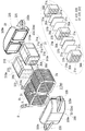
- FIG. 1 shows a state in which a part of the middle resin mold part 310m of one (front side) inner core part 310 is cut out.
- the reactor 1 is provided with the coil 2 formed by winding the coil
- the magnetic core 3 includes a plurality of columnar core pieces 31m, 32m, and the plurality of core pieces 31m,.
- the core piece 31m includes an end surface 31e disposed orthogonal to the axial direction of the coil 2 and a peripheral surface 31s disposed parallel to the axial direction of the coil 2. When the coil 2 is excited, the magnetic flux of the coil 2 passes so as to be orthogonal to the end face 31e of the core piece 31m and also passes parallel to the peripheral surface 31s.
- the resin part (middle resin mold part 310m (FIG. 2) here) is joined to at least a part of the outer periphery of the core piece 31m, and the region where the resin part is joined (here, the end face 31e of the core piece 31m).
- One of the features is that the concave portion 35A and the convex portion 36A are provided. This will be described in more detail below.
- the coil 2 includes a pair of cylindrical winding portions 2a and 2b formed by spirally winding a single continuous winding 2w as shown in FIGS. 1 and 2, and a winding 2w. And a connecting portion 2r that is formed from a part and connects the two winding portions 2a and 2b.
- Each winding part 2a, 2b is arranged in parallel (side by side) so that each axial direction is parallel.
- the winding 2w is a covered rectangular wire (so-called enameled wire) including a flat wire conductor (copper or the like) and an insulating coating (polyamideimide or the like) covering the outer periphery of the conductor, and the winding portion 2a. , 2b are edgewise coils.
- Both end portions of the winding 2w are drawn out from the winding portions 2a and 2b in an appropriate direction, and the terminal fittings 8 and 8 are connected to the conductor portions at the tips thereof.
- the coil 2 is electrically connected to an external device (not shown) such as a power source via the terminal fitting 8.
- the magnetic core 3 is provided with the part arrange
- the magnetic core 3 of this example is composed of a core part in which a part for constructing a magnetic path is covered with a resin, specifically, two inner core parts 310 and 310 and two outer core parts 320 and 320.
- the inner core component 310 includes a middle main body portion 31 that constructs a magnetic path, and a middle resin mold portion 310m.
- the outer core component 320 includes a side main body portion 32 that constructs a magnetic path, and a side resin mold portion 320m.
- the magnetic core 3 has a pair of outer core parts 320 and 320 assembled so as to connect a pair of side-by-side inner core parts 310 and 310, and the middle main body parts 31 and 31 and the side main body parts 32 and 32 are annularly arranged. When the coil 2 is excited, a closed magnetic circuit is formed.
- the middle body portion 31 is composed of a plurality of core pieces 31m made of a soft magnetic material and a material having a relative permeability smaller than that of the core piece 31m (for example, gap materials 31g made of nonmagnetic material such as alumina are alternately stacked to form a columnar shape (in this case, a rectangular parallelepiped shape with rounded corners).
- the core piece 31m and the gap material 31g are joined by an adhesive 370.
- a middle resin mold portion 310m is provided along the outer shape of the middle main body portion 31 so as to cover the entire outer periphery thereof.
- the core piece 31m is interposed between the core piece 32m adjacent to the core piece 31m and functions as a gap. That is, the reactor 1 of this example includes a plurality of gaps (gap material 31g and resin layer 372) made of different materials.
- the end surface 31e can be said to be a surface that forms a gap.
- the number of core pieces 31m and gap material 31g can be changed as appropriate.
- the adhesive 370 and the resin layer 372 constitute a resin portion 37 that is bonded to the outer periphery of the core piece 31m (here, the end surface 31e orthogonal to the magnetic flux of the coil 2).
- the side body part 32 is the core piece 32m comprised with the soft-magnetic material.
- the inner end surface 32e to which the pair of inner core components 310 and 310 are connected is a flat surface, and the upper surface and the lower surface have a dome shape whose cross-sectional area decreases from the inner end surface 32e outward ( Deformed trapezoidal shape).
- the inner end face 32e of the core piece 32m is also an end face orthogonal to the magnetic flux of the coil 2.
- Side resin mold part 320m is provided so that the outer periphery of side main-body part 32 may be covered along the external shape of side main-body part 32 except the area
- each of the core pieces 31m and 32m is a green compact formed substantially by metal particles and an insulating material interposed between the metal particles.
- the constituent resin of the middle resin mold part 310m and the side resin mold part 320m is polyphenylene sulfide (PPS) resin.
- PPS polyphenylene sulfide
- the above constituent resins include thermoplastic resins such as polytetrafluoroethylene (PTFE) resin, liquid crystal polymer (LCP), nylon 6, nylon 66, nylon 10T, nylon 9T, nylon 6T, and polybutylene terephthalate (PBT) resin. Can be mentioned.
- the green compact is typically formed from a raw material powder containing a metal powder such as iron or an iron alloy (Fe—Si alloy, Fe—Ni alloy, etc.) and a binder (resin etc.) or a lubricant as appropriate. Thereafter, it is obtained by performing a heat treatment for the purpose of removing distortions associated with molding.
- a coating powder obtained by subjecting a metal powder to an insulation treatment or a mixed powder obtained by mixing a metal powder and an insulating material as a raw material powder a compacted body in which an insulating material is interposed between metal particles can be obtained after molding. .
- a green compact formed of a coating powder in which metal particles are covered with an insulating coating is obtained.
- the reactor 1 can reduce the eddy current caused by the coil 2.
- Concave portion and convex portion A plurality of concave portions 35A and convex portions 36A surrounding each concave portion 35A are provided on both end surfaces 31e and 31e of the core piece 31m, which is arranged in the coil 2 and to which the resin portion 37 is joined. Prepare.
- the concave portion 35A and the convex portion 36A will be described with reference mainly to FIG.
- Each recess 35A has the same shape as shown in FIG. 3 (I), and is characterized by having a flat bottom 35b. Each recess 35A is characterized in that the planar shape of the bottom 35b is similar to the planar shape of the opening 35o.
- the planar shape of the opening 35o and the planar shape of the bottom 35b of each recess 35A are both rectangular. Then, one side (width Wo, FIG. 3 (I)) of the opening 35o and one side (width Wb, FIGS. 3 (II), (III)) of the bottom 35b are substantially equal, and the other side ( The length Lo (FIG. 3 (I)) and the other side of the bottom 35b (length Lb, FIGS. 3 (II) and (III)) are substantially equal. Therefore, the planar area of the opening 35o of the recess 35A and the planar area of the bottom 35b are substantially equal. That is, the bottom 35b substantially maintains the planar shape and size of the opening 35o.
- each recess 35A cross section taken along the cutting line (II)-(II) shown in FIG. 3 and a cross section in the length direction (cutting along (III)-(III) shown in FIG.
- Each of the vertical cross sections cut by the line is rectangular (cross section of FIG. 3 (II), cross section of (III)).
- the plurality of recesses 35A are aligned and arranged at a predetermined interval, and are uniformly formed over the entire end surface 31e of the core piece 31m. Specifically, the recesses 35A are arranged at equal intervals in both the vertical direction (vertical direction) and the horizontal direction (horizontal direction).
- the arrangement of the plurality of recesses 35A can be changed as appropriate. For example, it is possible to adopt a form (see FIG. 4 described later) in which a recess 35A for creating another row positioned above or below this row is disposed between adjacent recesses 35A, 35A that form a certain row. . Other arrangements are possible depending on the number of recesses 35A. The same applies to the later-described recesses 35B to 35G with respect to the arrangement of the plurality of recesses.
- a convex portion 36A exists so as to partition each concave portion 35A.
- the convex portion 36A is an unprocessed region that has not been processed when forming the plurality of concave portions 35A described above, and is formed along with the formation of the concave portion 35A.
- the convex portions 36A exist in a lattice shape in which the vertical and horizontal directions are orthogonal.
- the shape and size of the convex portion 36A (here, the width W 36 of the lattice) can be arbitrarily set according to the shape, size, number, and arrangement of the concave portion 35A.
- the shapes of other concave portions and convex portions will be specifically described.
- the end surface 31e of the core piece 31m has a plurality of recesses 35B (35C 1 , 35C 2 , 35D, 35E 1 , 35E 2 ) and surrounding recesses.
- convex portions 36B 36C, 36D, 36E to be partitioned.
- Each of the recesses 35B shown in FIG. 4 is a circular shape having the same diameter as the planar shape of the opening 35o.
- the bottom 35b of each recess 35B is formed by a plane substantially equal to the planar shape (circular shape) and size of the opening 35o.
- Such concave portions 35B are arranged at a predetermined interval.
- a recess 35B that forms another row positioned above or below this row is disposed between adjacent recesses 35B and 35B that form a row.
- the convex portion 36B defines these concave portions 35B.
- the recess 35B can make the planar shape of the opening 35o and the bottom 35b into a curved shape without corners.
- the planar shapes of the openings 35o 1 and 35o 2 are circular, and the sizes (diameters) of the openings 35o 1 and 35o 2 are different.
- the bottom portions 35b 1 and 35b 2 of the concave portions 35C 1 and 35C 2 are formed by a plane substantially equal to the planar shape (circular shape) and size of the opening portions 35o 1 and 35o 2 , and the bottom portions 35b 1 and 35b 2 are formed. Are different in size (diameter).
- Such large and small concave portions 35C 1 and 35C 2 are arranged at a predetermined interval.
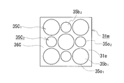
- a small circular recess 35C 2 is interposed between a large circular recess 35C 1 , 35C 1 that creates a row, and a large circular recess 35C 1 that creates another row located above or below this row. there are arranged in the position of the recess 35C 2 of the small circular of rows in the.
- a sequence recess 35B which is smaller recess 35C 2 between 35B interposed shown in FIG.
- the convex portion 36C defines the concave portions 35C 1 and 35C 2 .
- recesses 35C 1 of different sizes to one end surface 31e of, 35C 2 may comprise a.
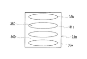
- Each of the recesses 35D shown in FIG. 6 has an elliptical shape in which the planar shape of the opening 35o has the same major axis and the same minor axis.
- the bottom 35b of each recess 35D is formed by a plane substantially equal to the planar shape (elliptical shape) and size of the opening 35o.
- Such recesses 35 ⁇ / b> D are arranged at a predetermined interval. In this example, they are arranged vertically.
- the convex portion 36D defines these concave portions 35D.
- the planar shapes of the openings 35o 1 and 35o 2 are elliptical, and the sizes (major axis and short axis) of the openings 35o 1 and 35o 2 are different.
- the bottom portions 35b 1 and 35b 2 of the concave portions 35E 1 and 35E 2 are each formed by a plane shape (elliptical shape) and a plane substantially equal to the size of the openings 35o 1 and 35o 2 , and the bottom portions 35b 1 and 35b 2.
- Such large and small concave portions 35E 1 and 35E 2 are arranged at a predetermined interval.
- the row formed by the small concave portions 35E 2 and 35E 2 arranged side by side and the row formed by the large concave portion 35E 1 are vertically arranged in random order.
- the convex portion 36E defines the concave portions 35E 1 and 35E 2 .
- the recesses 35E 1 and 35E 2 having different sizes can be provided on one end face 31e, or various arrangements can be made by combining large and small recesses.
- the recesses 35A to 35G shown in FIGS. 1 to 7 and FIG. 8 to be described later are merely examples.
- the planar shapes such as the opening 35o and the bottom 35b of the recess may be other shapes, for example, a polygonal shape such as a triangle or a pentagon, or an irregularly curved shape such as an oval.
- the number of the recessed parts with which one end surface 31e is equipped can be changed suitably, for example, can be only one.
- all the recesses have the same shape as shown in FIGS. 1, 4, and 6, and may include recesses having different planar shapes.
- a concave portion having a completely different planar shape such as a circular concave portion and a rectangular concave portion can be included.
- the depth D is the average depth measured along the diameter of the envelope circle for the planar shape of the opening 35o as described above.
- the size of the planar shape is measured based on a plane figure extracted along the circumference forming the opening 35o and the circumference forming the bottom 35b.
- the planar area may be calculated using the measured planar shape size.
- the maximum length dmax is the diameter of the envelope circle that extracts the planar shape of the bottom 35b as described above and encloses the extracted planar figure. For example, if the plane figure is a circle, the maximum length is a diameter, and if the plane figure is a quadrangle such as a square or a rectangle, the maximum length is a diagonal line.
- any resin can be easily filled as long as it is a recess that can be easily degassed or filled with resin.
- the depth D is, for example, about 50 ⁇ m or more and 100 ⁇ m or less.
- the maximum length dmax is, for example, 450 ⁇ m or more. Although it depends on the size of the core piece 31m, the maximum length dmax can be set to 1000 ⁇ m (1 mm) or more.
- each recess has a similar shape (an example in which the recesses 35C 1 and 35C 2 in FIG. 5 have the same contour and different plane areas, maximum lengths dmax, and the like), and have a recess having a different contour and size. (FIG. 7). For example, it can be set as the form provided with a deep recessed part and a shallow recessed part.
- Occupation ratio of recesses When one end surface 31e is viewed in plan view, the total area of the recesses 35A existing on the end surface 31e (including the case where there is one recess, corresponding to the total plane area of the opening 35o) The larger the is, the higher the bonding strength between the end face 31e and the resin part 37 can be.
- occupancy (total plane area of opening 35o / plane area of end face 31e) ⁇ 100 can be 10% or more, 15% or more, 20% or more, 25% or more, and further 50% or more. .
- Method for forming concave and convex portions For forming the concave portions 35A and the like, for example, laser processing such as laser light irradiation can be used.
- laser processing such as laser light irradiation
- the opening edge of the recess 35A may be slightly raised from the unprocessed region. This raised portion is considered to be formed when the constituent material of the core piece 31m is removed to the outside for forming the recess 35A during laser processing. It is expected that the contact area with the resin portion 37 can be further increased by the minute raised portion, and the resin portion 37 can be hooked depending on the shape of the raised portion. Further, when laser processing is performed, the bottom portion 35b may have very fine unevenness.
- the corner portion connecting the bottom surface 35b and the side surface of the concave portion 35A does not become an acute angle such as a right angle but may be rounded.
- the bottom portion 35b has a sufficiently large planar area, such a rounded corner portion is allowed.
- Irradiation conditions can be appropriately selected such that the size of the recess (depth D, planar area, maximum length dmax, etc.) has a desired value. In this example, laser processing is used.
- the metal particles are insulated, eddy current can be reduced.
- a concave portion is formed in such a green compact by laser processing or the like, a part of the insulating material can be removed. Even if a part of the insulating material is removed, an increase in eddy current caused by damage to the insulating material can be reduced as long as the insulation between adjacent metal particles is maintained or a small conductive loop is formed. Further, the insulating material remains on the convex portion 36A which is an unprocessed region where laser processing is not performed.
- the convex portion 36A exists so as to partition each concave portion 35A, the adjacent concave portions 35A and 35A are insulated by the insulating material of the convex portion 36A. Therefore, an eddy current does not flow between the adjacent recesses 35A and 35A, and the eddy current can be retained in the recess 35A even when the above-described conduction loop is formed by removing the insulating material. Therefore, by providing one end surface 31e as one end surface 31e (for example, a pressing surface formed by a die punch) in which an insulating material is interposed between metal particles, the end surface 31e is provided with a recess 35A, etc. At the time of excitation, even if the magnetic flux of the coil 2 passes through the end face 31e, generation of eddy current is small, and eddy current loss is expected to be very small.
- Other methods for forming recesses include cutting with a cutting tool. In the cutting process, the bottom 35d is expected to easily form a flat recess.
- each of the end faces 31e and 31e of the core piece 31m is formed with a plurality of concave portions 35A spaced apart at a predetermined interval, and the convex portions 36A are present by leaving unprocessed regions.
- the end surface 31e of the core piece 31m including the concave portion 35A and the convex portion 36A and the gap material 31g are joined by an adhesive 370 to form the middle main body portion 31.
- a sheet material is shown as the adhesive 370, but the adhesive 370 may be applied to one surface of the end surface 31e or the gap material 31g.
- the prepared middle main body parts 31 and 31 and separately prepared side main body parts 32 and 32 are used as cores, and the inner core parts 310 and 310 and the outer core parts 320 and 320 are manufactured by injection molding such as insert molding.
- a part (resin layer 372) of the middle resin mold part 310m is formed on each of the end faces 31e and 31e of the core pieces 31m and 31m located at each end part of the middle main body part 31, respectively.
- Adhesives 370 are joined to both end faces 31e of the core piece 31m that are joined and located in the middle of the middle main body 31.
- the inner core parts 310 and 310, the separately prepared coil 2 and the outer core parts 320 and 320 are assembled to form the annular magnetic core 3, and the coil 2 is supported by the magnetic core 3.
- the end surfaces 310e, 310e of the inner core components 310, 310 and the inner end surface of the outer core component 320 may be joined with an adhesive (not shown).
- the reactor 1 is obtained by the above process.
- the core piece 31m according to the first embodiment includes the recesses 35A (35B to 35E, etc.) and the projections 36A (36B to 36E, etc.) having a specific shape on at least a part of the outer periphery thereof.
- the resin part 37 can be firmly joined.
- the concave portion 35 ⁇ / b> A has a specific shape. Therefore, the core piece 31 m according to the first embodiment can contribute to the improvement of the manufacturability of the reactor 1 including the core piece 31 m and the resin portion 37.
- the reactor 1 of the first embodiment includes a core including a concave portion 35A (35B to 35E, etc.) and a convex portion 36A (36B to 36E, etc.) having a specific shape on at least a part of the outer periphery of the plurality of core pieces 31m, 32m.
- a core including a concave portion 35A (35B to 35E, etc.) and a convex portion 36A (36B to 36E, etc.) having a specific shape on at least a part of the outer periphery of the plurality of core pieces 31m, 32m.
- the core piece 31m has a large contact area between the end surface 31e of the core piece 31m and the resin portion 37 (here, the adhesive 370 and the resin layer 372) joined to the end surface 31e due to the plurality of concave portions 35A.
- the resin part 37 have high bonding strength and excellent bonding properties.
- the planar shape of the opening 35o and the arrangement of a plurality of recesses for example, can be rectangular (FIG. 1) or ellipse (FIGS. 6 and 7), or a combination of large and small recesses.
- FIG. 5 and 7 By arranging (FIGS. 5 and 7), separation of the resin portion 37 in a certain recess can be suppressed by another recess. That is, the reactor 1 can effectively increase the joining strength in an arbitrary shear direction between the core piece 31 m and the resin portion 37.
- the concave portion 35A and the like extends from the opening 35o to the bottom 35b, and generally maintains the size of the opening 35o, so that it is easy to deaerate and introduce resin. From this point, the constituent resin of the resin portion 37 can be easily filled, and the degassing time and filling time can be shortened. Further, even when various resins are used, it is expected that the resin can be easily and satisfactorily filled into the recesses 35A and the like.
- the planar shape of the opening 35o or the like is a simple shape with a small narrow area such as a circular shape or an elliptical shape, it is expected that degassing and resin filling can be performed better. Therefore, the manufacturability of the inner core component 310 can be further increased, and as a result, the manufacturability of the reactor 1 can be further increased.
- the reactor 1 includes a plurality of recesses 35A and the like on the end surface 31e orthogonal to the magnetic flux of the coil 2, as described above, eddy currents between adjacent recesses 35A and 35A can be suppressed by the intervention of the protrusions 36A and the like. . Therefore, the reactor 1 can reduce an increase in eddy current due to the presence of the recess 35A and the like, and is expected to have a low loss.
- the core piece 31m can contribute to the provision of the low-loss reactor 1.
- the core pieces 31m including the concave portions 35A and the convex portions 36A are arranged in the mold at a predetermined interval, and the adjacent core pieces 31m and 31m are arranged.
- the resin gap can be easily formed by filling the resin.
- the both end surfaces 31e and 31e of the core piece 31m are provided with the concave portions 35A and the convex portions 36A because the resin portion interposed between the core pieces 31m and 31m can be firmly joined.
- the resin portion interposed between the core pieces 31m and 31m also functions as an adhesive for joining the core pieces 31m and 31m in addition to the gap described above.
- a concave portion 35A and a convex portion 36A are provided on the curved outer peripheral surface connecting both the upper and lower surfaces and both surfaces of the core piece 32m.
- This form 1-3-1 is suitable for the case where each surface of the core piece 32m is covered with the side resin mold part 320m as described in the first embodiment.
- at least a part of the resin mold part 320m is a resin part bonded to at least a part of the outer periphery of the core piece 32m (here, the upper surface, the lower surface, and the curved outer peripheral surface).
- This form 1-3-2 is suitable when an adhesive is used as described above for joining the inner end face 32e and the end face 310e (FIG. 2) of the inner core component 310.
- the adhesive becomes a resin portion joined to a part of the outer periphery of the core piece 32m (here, the inner end face 32e orthogonal to the magnetic flux of the coil 2).
- the covering region of the side resin mold part 320m can be changed, and the entire outer periphery of the core piece 32m including the inner end face 32e can be covered with the resin mold part 320m.
- the upper and lower surfaces of the core piece 32m, a curved outer peripheral surface connecting both surfaces, and at least a part of the inner end surface 32e, preferably a recess 35A, a protrusion 36A, and the like can be provided.
- at least a part of the resin mold part 320m (for example, a flat resin layer covering the inner end face 32e) is formed on at least a part of the outer periphery of the core piece 32m (for example, the inner end face 32e). It becomes the joined resin part.
- both of the core pieces 31m and 32m included in the magnetic core 3 are provided with a resin portion on at least a part of the outer periphery thereof.
- both the core pieces 31m and 32m are provided with the concave portion 35A and the convex portion 36A, and the resin portion is firmly joined, so that the function of the resin portion (insulation ensuring with the coil 2 is ensured). , Maintenance of gap length, maintenance of integration, protection from the environment, mechanical protection, etc.).
- the core piece 31m is not provided with the concave portion 35A, the convex portion 36A, and the like, and may be provided with the concave portion 35A, the convex portion 36A, and the like only at least a part of the outer periphery of the core piece 32m.
- the core piece 32m is not covered with the coil 2, unlike the core piece 31m covered with the coil 2, there is a risk of contact with surrounding components.
- at least a part of the outer periphery of the core piece 32m is covered with the resin portion (side resin mold portion 320m), and the resin portion is firmly joined by the concave portion 35A, the convex portion 36A, etc.
- the core piece 32m can be well protected from the environment and mechanically protected.
- the reactor 1 is described in which the middle main body portion 31 in which the plurality of core pieces 31m and the gap material 31g are stacked is integrally covered with the middle resin mold portion 310m.
- it can be set as the reactor provided with two or more covering core pieces which formed the resin mold part for every 31 m of core pieces.
- Each coated core piece includes a concave portion 35A, a convex portion 36A, and the like on both end faces 31e and 31e of the core piece 31m, and a part of the resin mold portion (a flat resin layer) is joined.
- this reactor can omit the gap material 31g and can reduce the number of parts.
- the reactor 1 in which the magnetic core 3 includes four core parts has been described.
- a reactor including a U-shaped core part 31 and one side main body part 32 assembled in a U shape and integrally held in the resin mold part, and one outer core part can be used.
- Embodiment 2 In the first embodiment, the form in which the concave portions 35A and the convex portions 36A are provided on both end surfaces 31e and 31e of the core piece 31m provided in the middle main body portion 31 has been described.
- the core piece 31m of Embodiment 2 shown in FIG. 8 is a form provided with a recessed part and a convex part on the peripheral surface 31s parallel to the magnetic flux of the coil 2 (FIG. 2) in addition to the end face 31e.
- each recess 35G has a circular shape in which the planar shape of the opening 35o has the same diameter, and the bottom 35b is substantially equal to the planar shape of the opening 35o.
- the concave portions 35G are arranged vertically and horizontally with a predetermined interval. The size (depth D, maximum length dmax, planar area, etc.) of each recess 35G is also the same.
- the shape, size, the number of concave portions, the arrangement and the like of the concave portions 35G and the convex portions 36G provided on the end surface 31e and the peripheral surface 31s are equal, but the concave portions provided on the respective surfaces 31e and 31s satisfy these requirements.
- the end surface 31e includes a concave portion 35A and a convex portion 36A that are rectangular in a plan view shown in FIG. 1
- the peripheral surface 31s includes a concave portion 35G and a convex portion 36G that are circular in a plan view shown in FIG. can do.
- all four peripheral surfaces 31s to 31s are provided with concave portions 35G and convex portions 36G.
- at least one peripheral surface 31s may be provided with no concave portions and convex portions. .
- a resin part such as a middle resin mold part 310m (FIG. 2) or an adhesive 370 (FIG. 2) is joined to the entire circumference of the core piece 31m. Therefore, by providing the recesses 35G and the projections 36G on both the end surface 31e and the peripheral surface 31s of the core piece 31m, this reactor can improve the bonding strength with the resin part and ensure good resin filling properties. Both improvement of manufacturability can be achieved.
- this reactor has the resin mold part 310m firmly joined to both the end face 31e and the peripheral face 31s, and can further suppress peeling, and can firmly hold the state in which the plurality of core pieces 31m are integrated.
- this reactor is expected to be able to maintain the integration of the plurality of core pieces 31m over a long period of time and to further suppress an increase in vibration and noise.
- the core piece 31m of the second embodiment can contribute to the provision of a reactor that is excellent in bondability with the resin portion, is excellent in manufacturability, and has less vibration and noise.
- the reactor according to the third embodiment includes the concave portions 35A and the convex portions 36A on at least a part of the outer periphery of the core pieces 31m and 32m, thereby improving the bonding strength with the sealing resin and ensuring good filling properties of the resin. It is possible to achieve both the improvement of the manufacturability of the reactor.
- the core pieces 31m and 32m can contribute to providing a reactor that is excellent in bondability with the sealing resin and that can be easily filled with the sealing resin and has excellent manufacturability.
- the reactor 1 shown in FIG. 1 includes the following engaging portion, a mounting portion 325, and a partition portion configured by a middle resin mold portion 310m and a side resin mold portion 320m.
- at least one of the engaging portion, the attaching portion 325, and the partition portion can be omitted.
- the middle resin mold part 310m has a thin area in the vicinity of the end face 31e in the part covering the peripheral surface 31s of the middle main body part 31.
- the side resin mold part 320m includes two cylindrical parts provided so as to protrude from the inner end face of the outer core part 320. The thin region and the cylindrical portion function as an engaging portion.
- the side resin mold part 320m has a protruding piece protruding outward.
- a bolt hole 325 h is provided in the projecting piece, and this projecting piece is used for the attachment portion 325.
- the side resin mold part 320m protrudes from the inner end surface of the outer core part 320, and a plate piece provided between the two cylinder parts. Prepare.
- This board piece functions as a partition part, and ensures insulation of both winding parts 2a and 2b.
- reactors of the first to third embodiments and the modified examples described above can include the following members. At least one of these members can be omitted.
- a sensor (not shown) for measuring a physical quantity such as a reactor 1 such as a temperature sensor, a current sensor, a voltage sensor, or a magnetic flux sensor can be provided.
- a heat radiation plate (not shown) can be provided at any location on the outer peripheral surface of the coil 2.
- the installation surface (here, the lower surface) of the coil 2 is provided with a heat dissipation plate, the heat of the coil 2 can be well transmitted to the installation object such as the converter case through the heat dissipation plate, thereby improving the heat dissipation.
- a material having excellent thermal conductivity for example, a metal such as aluminum or an alloy thereof, a non-metal such as alumina, or the like can be used.
- the heat radiating plate can be fixed to the assembly of the coil 2 and the magnetic core 3 by, for example, a bonding layer described later.
- At least the installation surface (here, the lower surface) of the coil 2 can be provided with a bonding layer (not shown).
- the bonding layer By providing the bonding layer, the coil 2 can be firmly fixed to the heat sink when the installation target or the above heat sink is provided, the movement of the coil 2 is restricted, the heat dissipation is improved, the installation target or the heat sink Fixing stability can be achieved.
- Constituent material of the bonding layer contains an insulating resin, particularly ceramic filler, and has excellent heat dissipation (for example, thermal conductivity is 0.1 W / m ⁇ K or more, further 1 W / m ⁇ K or more, especially 2 W / M ⁇ K or more).
- the resin include thermosetting resins such as epoxy resin, silicone resin, and unsaturated polyester, and thermoplastic resins such as PPS resin and LCP.
- this invention is not limited to these illustrations, is shown by the claim, and it is intended that all the changes within the meaning and range equivalent to the claim are included.
- it can be set as the reactor provided with a coil with only one winding part.
- the core piece provided with the above-mentioned specific recessed part and convex part can be utilized for the component of the magnetic core of magnetic components other than a reactor.
- the core piece of the present invention can be suitably used for components of magnetic parts such as a reactor, a transformer, a motor, and a choke coil.
- the reactor of the present invention includes various on-vehicle converters (typically DC-DC converters) mounted on vehicles such as hybrid vehicles, plug-in hybrid vehicles, electric vehicles, and fuel cell vehicles, and converters for air conditioners. It can utilize suitably for the component of a converter and a power converter.
Landscapes
- Engineering & Computer Science (AREA)
- Power Engineering (AREA)
- Coils Or Transformers For Communication (AREA)
Abstract
樹脂部との接合性に優れる上に、製造性にも優れるコア片及びリアクトルを提供する。 巻線を巻回してなるコイルの内外に配置される磁性コアを構成するコア片であって、前記コア片の外周の少なくとも一部に樹脂部が接合される領域を有し、前記樹脂部が接合される領域は、凹部と、前記凹部の周囲を囲む凸部とを備え、前記凹部は、開口部と、前記開口部と相似形状である平面状の底部とを備えるコア片。巻線を巻回してなるコイルと、前記凹部及び前記凸部を備えるコア片を含む複数のコア片を備える磁性コアと、前記複数のコア片の外周のうち、少なくとも前記凹部及び前記凸部を備える領域に接合された樹脂部とを備えるリアクトル。
Description
本発明は、リアクトルなどの磁気部品に備える磁性コアを構成するコア片、ハイブリッド自動車などの車両に搭載される車載用DC-DCコンバータや電力変換装置の構成部品などに利用されるリアクトルに関する。特に、樹脂部との接合性に優れる上に、製造性にも優れるコア片及びリアクトルに関する。
電圧の昇圧動作や降圧動作を行う回路の部品の一つに、リアクトルがある。特許文献1は、ハイブリッド自動車などの車両に載置されるコンバータに利用されるリアクトルとして、巻線を螺旋状に巻回してなるコイルと、複数のコア片を組み合わせて環状に形成される磁性コアとを備えるものを開示している。また、特許文献1は、各コア片を絶縁被覆層(樹脂層)で覆ったり、複数のコア片を一体に樹脂層で覆ったりすること、コイル内に配置されるコア片の端面を覆う樹脂層をギャップに利用することを開示している。
樹脂部との接合性に優れる上に、製造性にも優れるコア片及びリアクトルが望まれている。
リアクトルなどの磁気部品に備えるコイルは、通電時にはジュール熱によって発熱し、非通電時には発熱しない。特に、車載用コンバータに利用されるリアクトルなどのように、通電電流値が大きい場合には、コイルの発熱が大きい。従って、コイル近傍に配置されるコア片やコア片を覆う樹脂層は、コイルに起因するヒートサイクルを受けて熱伸縮する。鉄などの金属を主体とするコア片と、樹脂とでは、熱膨張係数が異なるため、熱伸縮に起因して樹脂層がコア片から剥離する恐れがある。樹脂層が剥離することで、樹脂層の機能を十分に発揮できない恐れがある。例えば、コイル内に配置されるコア片について樹脂層が剥離した箇所は、コイルとの間の絶縁の弱点となる可能性や、コア片間に設けられるギャップ長が変動する可能性がある。また、例えば、樹脂層が剥離して複数のコア片の一体化が不十分になると、剥離前後の共振周波数が変化して、剥離前と比較して振動や騒音が大きくなる恐れがある。
そこで、本発明者らは、コア片と樹脂部との接合性を高めるために、コア片における樹脂部との接合面を凹凸形状にすること、具体的にはコア片の外周に溝を形成して樹脂部との接触面積を増大することを検討した。しかし、例えば、レーザ加工によって直線状の細い溝や点状の小さい溝などを形成した場合、レーザのエネルギーが溝の開口部から底部に向かうほど小さくなる結果、図9に示すように溝350の断面形状がU字状やV字状となり得る。即ち、溝350の開口部350oから底部350bに向かうにつれて内部空間が狭くなり(平面面積が小さくなり)、底部350bが線状又は点状になり得る。このような溝350では、樹脂の種類や粘度、樹脂の充填条件などによっては溝350内の隅々にまで樹脂が充填されず、溝350による樹脂部との接触面積の増大効果を十分に発揮できない恐れがある。接触面積を大きくするために溝350が深い場合には、樹脂の充填性に更に劣ると考えられる。また、V字状などの溝350では、溝350内の脱気が不十分なまま樹脂が開口部350oを覆って、溝350内に気体が留まる恐れがある。この気体が熱膨張して周囲の樹脂を押し上げるなどして、溝350における樹脂の未充填部分が樹脂部の剥離の起点になり得る。脱気時間や充填時間を長くしたり、樹脂の種類や粘度などを溝350の大きさなどに対応して調整や選択などしたりする場合には、製造時間の長大化や使用可能な樹脂の制限を招く。その結果、樹脂部を備えるコア片の製造性の低下、ひいてはリアクトルの製造性の低下を招く。
本発明は、上述の事情を鑑みてなされたものであり、その目的の一つは、樹脂部との接合性に優れる上に、樹脂部を形成し易いコア片を提供することにある。本発明の他の目的は、樹脂部との接合性に優れる上に、製造性にも優れるリアクトルを提供することにある。
本発明の一態様に係るコア片は、巻線を巻回してなるコイルの内外に配置される磁性コアを構成するコア片であって、前記コア片の外周の少なくとも一部に樹脂部が接合される領域を有し、前記樹脂部が接合される領域は、凹部と、前記凹部の周囲を囲む凸部とを備え、前記凹部は、開口部と、前記開口部と相似形状である平面状の底部とを備える。
本発明の一態様に係るリアクトルは、巻線を巻回してなるコイルと、上記本発明の一態様に係るコア片を含む複数のコア片を備える磁性コアと、前記複数のコア片の外周のうち、少なくとも前記凹部及び前記凸部を備える領域に接合された樹脂部とを備える。
上記のコア片は、樹脂部との接合性に優れる上に、樹脂部を形成し易い。上記のリアクトルは、樹脂部との接合性に優れる上に、製造性にも優れる。
[本発明の実施の形態の説明]
最初に、本発明の実施態様を列記して説明する。
(1) 本発明の一態様に係るコア片は、巻線を巻回してなるコイルの内外に配置される磁性コアを構成するコア片であって、上記コア片の外周の少なくとも一部に樹脂部が接合される領域を有し、上記樹脂部が接合される領域は、凹部と、上記凹部の周囲を囲む凸部とを備え、上記凹部は、開口部と、上記開口部と相似形状である平面状の底部とを備える。
最初に、本発明の実施態様を列記して説明する。
(1) 本発明の一態様に係るコア片は、巻線を巻回してなるコイルの内外に配置される磁性コアを構成するコア片であって、上記コア片の外周の少なくとも一部に樹脂部が接合される領域を有し、上記樹脂部が接合される領域は、凹部と、上記凹部の周囲を囲む凸部とを備え、上記凹部は、開口部と、上記開口部と相似形状である平面状の底部とを備える。
「相似形状で平面状」とは、以下とする。凹部の開口部をつくる周縁に沿って、凹部の開口部の平面形状を抽出し、抽出した平面図形を内包する包絡円をとる。この包絡円の直径に沿って、凹部の深さをレーザ変位計などの公知の測定装置を用いて測定し、その平均を凹部の平均深さとする。上記の直径上の各測定値と平均深さとの差が平均深さの30%以内であれば、この凹部は、深さが実質的に一様であり、底部が平面とみなせる程度に平坦であるといえる。また、上記包絡円における任意の直径について、上記平均深さが30%以内である場合、底部の平面形状は、開口部の平面形状に相似しているといえる。更に、このような凹部は、底部の平面面積が開口部の平面面積を十分に維持しているといえる(例えば、開口部の面積の70%以上を満たす)。そこで、上述の平均深さとの差が平均深さの30%以内である場合を相似形状で平面状とする。即ち、上記のコア片では、凹部の底部が非常に微細な凹凸を有している場合を許容する。
上記のコア片は、樹脂部が接合される領域に特定の凹部及び凸部を備えることで、樹脂部との接合性に優れる。
詳しくは、上記のコア片における樹脂部が接合される領域が凹部及び凸部によって凹凸形状になっているため、コア片と樹脂との接触面積が、凹部及び凸部が無い場合(特許文献1など)に比較して大きい。従って、上記のコア片は、樹脂部との接合強度の向上を図ることができる。
詳しくは、上記のコア片における樹脂部が接合される領域が凹部及び凸部によって凹凸形状になっているため、コア片と樹脂との接触面積が、凹部及び凸部が無い場合(特許文献1など)に比較して大きい。従って、上記のコア片は、樹脂部との接合強度の向上を図ることができる。
かつ、上記のコア片は、凹部が特定の形状であることで、樹脂部を備えるコア片の製造性に優れ、ひいてはリアクトルの製造性の向上に寄与する。
詳しくは、凹部の底部が実質的に平面で形成され、かつ、この底部の平面形状と開口部の平面形状とが実質的に等しい。即ち、凹部をその深さ方向にみたとき、開口部の平面面積が底部に至るまで概ね維持されて、凹部の内部空間が開口部から底部に至るまで概ね一様な大きさであるといえる。そのため、特定の凹部を備える上記のコア片は、断面形状がV字状などである溝350(図9)を備える場合と比較して、樹脂部を形成する際に脱気及び樹脂の充填を行い易く、脱気時間や樹脂の充填時間を短縮できると期待される。また、この特定の凹部であれば、任意の樹脂を容易に充填できると期待される。これらの点から、樹脂部の製造性に優れて、樹脂部を備えるコア片を製造し易い。
詳しくは、凹部の底部が実質的に平面で形成され、かつ、この底部の平面形状と開口部の平面形状とが実質的に等しい。即ち、凹部をその深さ方向にみたとき、開口部の平面面積が底部に至るまで概ね維持されて、凹部の内部空間が開口部から底部に至るまで概ね一様な大きさであるといえる。そのため、特定の凹部を備える上記のコア片は、断面形状がV字状などである溝350(図9)を備える場合と比較して、樹脂部を形成する際に脱気及び樹脂の充填を行い易く、脱気時間や樹脂の充填時間を短縮できると期待される。また、この特定の凹部であれば、任意の樹脂を容易に充填できると期待される。これらの点から、樹脂部の製造性に優れて、樹脂部を備えるコア片を製造し易い。
(2) 上記のコア片の一例として、上記コイルの磁束に直交する端面に、複数の上記凹部と、隣り合う上記凹部を区画する上記凸部とを備える形態が挙げられる。
上記形態は、上記端面に樹脂部を強固に接合できる。上記端面に接合された樹脂部は、上記形態のコア片をリアクトルなどの磁気部品に用いた場合にギャップとして利用できる。この場合に、ギャップとなる樹脂部がコア片に強固に接合されているため、樹脂部の剥離に起因するギャップ長の変動などを抑制できる。また、この場合、ギャップ材を省略できるため、リアクトルなどの部品点数を低減できる。従って、上記形態は、リアクトルなどにおけるギャップ長の維持、及びリアクトルなどの製造性の向上に寄与できる。
(3) 上記のコア片の一例として、上記コイルの磁束に平行する周面に、上記凹部及び上記凸部を備える形態が挙げられる。
上記形態は、上記周面に樹脂部を強固に接合できる。そのため、上記形態のコア片をリアクトルなどの磁気部品に用いた場合に、上記周面に接合された樹脂部によって、長期に亘り、コイルとコア片との間の良好な絶縁、コア片の機械的保護、環境からの保護などを図ることができる。リアクトルなどが上記形態のコア片を含む複数のコア片を備えており、樹脂部が隣り合うコア片の周面に一体に接合されている場合には、上記形態のコア片に樹脂部が強固に接合されるため、この樹脂部によって複数のコア片が強固に一体化される。樹脂部が接合された複数のコア片の全てに上記凹部及び凸部を備える場合には、隣り合うコア片が樹脂部によってより強固に一体化される。このように一体化されたコア片群は、樹脂部の剥離に起因する絶縁性能の劣化や振動・騒音の増大を抑制できる。従って、上記の形態は、リアクトルなどに用いられた場合に、長期に亘り、コイルとコア片との間の絶縁の確保、優れた耐振性の保持に寄与できる。
(4) 上記のコア片の一例として、金属粒子と上記金属粒子間に介在する絶縁材とを備える圧粉成形体である形態が挙げられる。
上記形態は、金属粒子間が絶縁材によって絶縁されるため、渦電流を低減できる。また、凹部がコア片におけるコイルの磁束に直交する端面に設けられている形態(上述の(2)の形態など)では、凹部に起因する渦電流の増大を低減できる。
(5) 本発明の一態様に係るリアクトルは、巻線を巻回してなるコイルと、上述の(1)~(4)のいずれか一つに記載のコア片を含む複数のコア片を備える磁性コアと、上記複数のコア片の外周のうち、少なくとも上記凹部及び上記凸部を備える領域に接合された樹脂部とを備える。換言すれば、このリアクトルは、巻線を巻回してなるコイルと、複数のコア片を備える磁性コアと、前記複数のコア片の外周の少なくとも一部に接合された樹脂部とを備え、前記樹脂部が接合された領域は、凹部と、前記凹部の周囲を囲む凸部とを備え、前記凹部は、開口部と、前記開口部と相似形状である平面状の底部とを備える。
上記のリアクトルは、樹脂部との接合性に優れる上記のコア片を備えることで、上述のように樹脂部との接合性に優れる。かつ、上記のリアクトルは、特定形状の凹部が設けられた上記のコア片を構成要素とすることで、樹脂部の形成時に脱気や樹脂の充填を行い易く、製造性に優れる。上記のリアクトルの具体的形態として、複数のコア片のうち、上記の凹部及び凸部を備えるコア片が一つであり、このコア片の外周のうち、少なくとも凹部及び凸部の形成領域に樹脂部が接合されている形態、上記の凹部及び凸部を備えるコア片が複数であり、これらの複数のコア片の外周のうち、少なくとも上記の凹部及び凸部の形成領域に樹脂部が接合されている形態が挙げられる。後者は、特に、隣り合うコア片の双方が上記の凹部及び凸部を備えており、樹脂部が、隣り合うコア片に亘って接合されている形態が挙げられる。この形態は、上述の(3)で説明したように、長期に亘り、コイルとコア片との間の絶縁性、耐振性に優れる。
[本発明の実施形態の詳細]
以下、図面を参照して、本発明の実施形態に係るコア片及びリアクトルを具体的に説明する。図中の同一符号は、同一名称物を示す。
以下、図面を参照して、本発明の実施形態に係るコア片及びリアクトルを具体的に説明する。図中の同一符号は、同一名称物を示す。
[実施形態1]
図1~図7を参照して、実施形態1のコア片31m及びコア片31mを備えるリアクトル1を説明する。図1~図7、後述する図8に示す凹部35A~35G、凸部36A~36Gは、分かり易いように誇張して示し、実際の大きさ(平面面積、幅Wo,Wb、長さLo,Lb、深さD、幅W36など)とは異なる場合がある。また、図2では、一方(手前側)の内側コア部品310のミドル樹脂モールド部310mの一部を切欠いた状態を示す。
図1~図7を参照して、実施形態1のコア片31m及びコア片31mを備えるリアクトル1を説明する。図1~図7、後述する図8に示す凹部35A~35G、凸部36A~36Gは、分かり易いように誇張して示し、実際の大きさ(平面面積、幅Wo,Wb、長さLo,Lb、深さD、幅W36など)とは異なる場合がある。また、図2では、一方(手前側)の内側コア部品310のミドル樹脂モールド部310mの一部を切欠いた状態を示す。
(リアクトル)
・全体構成
リアクトル1は、巻線2wを螺旋状に巻回してなるコイル2と、コイル2の内外に配置されて閉磁路を形成する磁性コア3とを備える。磁性コア3は、複数の柱状のコア片31m,32mを備え、コイル2内に複数のコア片31m,…が配置される。コア片31mは、コイル2の軸方向に直交に配置される端面31eと、コイル2の軸方向に平行に配置される周面31sとを備える。コイル2が励磁されると、コイル2の磁束は、コア片31mの端面31eに直交するように通過すると共に、周面31sに平行に通過する。コア片31mの外周の少なくとも一部に樹脂部(ここではミドル樹脂モールド部310m(図2))が接合される点、この樹脂部が接合される領域(ここではコア片31mの端面31e)に特定の凹部35A及び凸部36Aを備える点を特徴の一つとする。以下、より詳細に説明する。
・全体構成
リアクトル1は、巻線2wを螺旋状に巻回してなるコイル2と、コイル2の内外に配置されて閉磁路を形成する磁性コア3とを備える。磁性コア3は、複数の柱状のコア片31m,32mを備え、コイル2内に複数のコア片31m,…が配置される。コア片31mは、コイル2の軸方向に直交に配置される端面31eと、コイル2の軸方向に平行に配置される周面31sとを備える。コイル2が励磁されると、コイル2の磁束は、コア片31mの端面31eに直交するように通過すると共に、周面31sに平行に通過する。コア片31mの外周の少なくとも一部に樹脂部(ここではミドル樹脂モールド部310m(図2))が接合される点、この樹脂部が接合される領域(ここではコア片31mの端面31e)に特定の凹部35A及び凸部36Aを備える点を特徴の一つとする。以下、より詳細に説明する。
・コイル
コイル2は、図1,図2に示すように1本の連続する巻線2wを螺旋状に巻回して形成された一対の筒状の巻回部2a,2bと、巻線2wの一部から形成されて両巻回部2a,2bを接続する連結部2rとを備える。各巻回部2a,2bは、各軸方向が平行するように並列(横並び)されている。この例では、巻線2wは、平角線の導体(銅など)と、この導体の外周を覆う絶縁被覆(ポリアミドイミドなど)とを備える被覆平角線(いわゆるエナメル線)であり、巻回部2a,2bはエッジワイズコイルである。巻線2wの両端部はいずれも、巻回部2a,2bから適宜な方向に引き出されて、その先端の導体部分に端子金具8,8が接続される。コイル2は、端子金具8を介して電源などの外部装置(図示せず)に電気的に接続される。
コイル2は、図1,図2に示すように1本の連続する巻線2wを螺旋状に巻回して形成された一対の筒状の巻回部2a,2bと、巻線2wの一部から形成されて両巻回部2a,2bを接続する連結部2rとを備える。各巻回部2a,2bは、各軸方向が平行するように並列(横並び)されている。この例では、巻線2wは、平角線の導体(銅など)と、この導体の外周を覆う絶縁被覆(ポリアミドイミドなど)とを備える被覆平角線(いわゆるエナメル線)であり、巻回部2a,2bはエッジワイズコイルである。巻線2wの両端部はいずれも、巻回部2a,2bから適宜な方向に引き出されて、その先端の導体部分に端子金具8,8が接続される。コイル2は、端子金具8を介して電源などの外部装置(図示せず)に電気的に接続される。
・磁性コア
磁性コア3は、コイル2(巻回部2a,2b)内に配置される部分と、コイル2が実質的に配置されず、コイル2から突出した部分とを備える。この例の磁性コア3は、磁路を構築する部分が樹脂で覆われたコア部品、具体的には2個の内側コア部品310,310と2個の外側コア部品320,320とを構成要素とする。図2に示すように、内側コア部品310は、磁路を構築するミドル本体部31と、ミドル樹脂モールド部310mとを備える。外側コア部品320は、磁路を構築するサイド本体部32と、サイド樹脂モールド部320mとを備える。磁性コア3は、横並びされた一対の内側コア部品310,310を繋ぐように一対の外側コア部品320,320が組み付けられて、ミドル本体部31,31、サイド本体部32,32が環状に配置され、コイル2を励磁したときに閉磁路を形成する。
磁性コア3は、コイル2(巻回部2a,2b)内に配置される部分と、コイル2が実質的に配置されず、コイル2から突出した部分とを備える。この例の磁性コア3は、磁路を構築する部分が樹脂で覆われたコア部品、具体的には2個の内側コア部品310,310と2個の外側コア部品320,320とを構成要素とする。図2に示すように、内側コア部品310は、磁路を構築するミドル本体部31と、ミドル樹脂モールド部310mとを備える。外側コア部品320は、磁路を構築するサイド本体部32と、サイド樹脂モールド部320mとを備える。磁性コア3は、横並びされた一対の内側コア部品310,310を繋ぐように一対の外側コア部品320,320が組み付けられて、ミドル本体部31,31、サイド本体部32,32が環状に配置され、コイル2を励磁したときに閉磁路を形成する。
・・ミドル本体部
ミドル本体部31は、図2の破線円内に示すように、軟磁性材料によって構成された複数のコア片31m,…と、コア片31mよりも比透磁率が小さい材料(例えば、アルミナなどの非磁性材)からなるギャップ材31gとが交互に積層されて柱状(ここでは角部を丸めた直方体状)に形成されている。この例では、コア片31mとギャップ材31gとは接着剤370によって接合されている。このミドル本体部31の外形に沿って、その外周全体を覆うようにミドル樹脂モールド部310mが設けられている。樹脂モールド部310mの一部、具体的にはミドル本体部31の各端面(ここではコア片31mの端面31e,31e)を覆う平板状の樹脂層372は、ミドル本体部31のコア片31mと、このコア片31mに隣り合うサイド本体部32のコア片32mとの間に介在されて、ギャップとして機能する。即ち、この例のリアクトル1は、異なる材料から構成された複数のギャップ(ギャップ材31g及び樹脂層372)を備える。また、端面31eはギャップを形成する面といえる。コア片31m、ギャップ材31gの個数は適宜変更できる。
ミドル本体部31は、図2の破線円内に示すように、軟磁性材料によって構成された複数のコア片31m,…と、コア片31mよりも比透磁率が小さい材料(例えば、アルミナなどの非磁性材)からなるギャップ材31gとが交互に積層されて柱状(ここでは角部を丸めた直方体状)に形成されている。この例では、コア片31mとギャップ材31gとは接着剤370によって接合されている。このミドル本体部31の外形に沿って、その外周全体を覆うようにミドル樹脂モールド部310mが設けられている。樹脂モールド部310mの一部、具体的にはミドル本体部31の各端面(ここではコア片31mの端面31e,31e)を覆う平板状の樹脂層372は、ミドル本体部31のコア片31mと、このコア片31mに隣り合うサイド本体部32のコア片32mとの間に介在されて、ギャップとして機能する。即ち、この例のリアクトル1は、異なる材料から構成された複数のギャップ(ギャップ材31g及び樹脂層372)を備える。また、端面31eはギャップを形成する面といえる。コア片31m、ギャップ材31gの個数は適宜変更できる。
接着剤370及び樹脂層372は、コア片31mの外周(ここではコイル2の磁束に直交する端面31e)に接合される樹脂部37を構成する。
・・サイド本体部
サイド本体部32は、軟磁性材料によって構成されたコア片32mである。この例に示すコア片32mは、一対の内側コア部品310,310が接続される内端面32eが平面であり、上面及び下面が内端面32eから外方に向かって断面積が小さくなるドーム状(変形台形状)である。コア片32mの内端面32eも、コイル2の磁束に直交する端面である。内端面32eのうち、内側コア部品310,310が接続される領域を除いて、サイド本体部32の外形に沿ってサイド本体部32の外周を覆うようにサイド樹脂モールド部320mが設けられている。
サイド本体部32は、軟磁性材料によって構成されたコア片32mである。この例に示すコア片32mは、一対の内側コア部品310,310が接続される内端面32eが平面であり、上面及び下面が内端面32eから外方に向かって断面積が小さくなるドーム状(変形台形状)である。コア片32mの内端面32eも、コイル2の磁束に直交する端面である。内端面32eのうち、内側コア部品310,310が接続される領域を除いて、サイド本体部32の外形に沿ってサイド本体部32の外周を覆うようにサイド樹脂モールド部320mが設けられている。
・・材質
この例では、コア片31m,32mはいずれも、金属粒子と、金属粒子間に介在する絶縁材とによって実質的に構成される圧粉成形体である。ミドル樹脂モールド部310m,サイド樹脂モールド部320mの構成樹脂は、ポリフェニレンサルファイド(PPS)樹脂である。その他、上記構成樹脂は、ポリテトラフルオロエチレン(PTFE)樹脂、液晶ポリマー(LCP)、ナイロン6、ナイロン66、ナイロン10T、ナイロン9T、ナイロン6T、ポリブチレンテレフタレート(PBT)樹脂などの熱可塑性樹脂が挙げられる。
この例では、コア片31m,32mはいずれも、金属粒子と、金属粒子間に介在する絶縁材とによって実質的に構成される圧粉成形体である。ミドル樹脂モールド部310m,サイド樹脂モールド部320mの構成樹脂は、ポリフェニレンサルファイド(PPS)樹脂である。その他、上記構成樹脂は、ポリテトラフルオロエチレン(PTFE)樹脂、液晶ポリマー(LCP)、ナイロン6、ナイロン66、ナイロン10T、ナイロン9T、ナイロン6T、ポリブチレンテレフタレート(PBT)樹脂などの熱可塑性樹脂が挙げられる。
圧粉成形体は、代表的には、鉄や鉄合金(Fe-Si合金、Fe-Ni合金など)といった金属の粉末と、適宜バインダ(樹脂など)や潤滑剤とを含む原料粉末を成形した後、成形に伴う歪みの除去などを目的とした熱処理を施して得られる。金属粉末に絶縁処理を施した被覆粉末や、金属粉末と絶縁材とを混合した混合粉末を原料粉末に用いることで、成形後、金属粒子間に絶縁材が介在する圧粉成形体が得られる。代表的には、金属粒子が絶縁被覆で覆われた被覆粉末から構成される圧粉成形体が得られる。金属粒子間に絶縁材が介在する圧粉成形体は絶縁性に優れるため、このような圧粉成形体の一面をコア片31m,32mにおけるコイル2の磁束に直交に配置される面とすると、リアクトル1はコイル2に起因する渦電流を低減できる。
・・凹部及び凸部
コイル2内に配置され、樹脂部37が接合されるコア片31mの両端面31e,31eにそれぞれ、複数の凹部35Aと、各凹部35Aの周囲を囲む凸部36Aとを備える。以下、図3を主として参照して凹部35A及び凸部36Aを説明する。
コイル2内に配置され、樹脂部37が接合されるコア片31mの両端面31e,31eにそれぞれ、複数の凹部35Aと、各凹部35Aの周囲を囲む凸部36Aとを備える。以下、図3を主として参照して凹部35A及び凸部36Aを説明する。
・・・概要
各凹部35Aは、図3(I)に示すようにいずれも同一形状であり、平面状の底部35bを備える点を特徴の一つとする。また、各凹部35Aは、底部35bの平面形状が開口部35oの平面形状に相似する点を特徴の一つとする。
各凹部35Aは、図3(I)に示すようにいずれも同一形状であり、平面状の底部35bを備える点を特徴の一つとする。また、各凹部35Aは、底部35bの平面形状が開口部35oの平面形状に相似する点を特徴の一つとする。
この例では、各凹部35Aの開口部35oの平面形状及び底部35bの平面形状はいずれも長方形状である。そして、開口部35oの一辺(幅Wo、図3(I))と底部35bの一辺(幅Wb、図3(II),(III))とが実質的に等しく、開口部35oの他辺(長さLo、図3(I))と底部35bの他辺(長さLb、図3(II),(III))とが実質的に等しい。そのため、凹部35Aの開口部35oの平面面積と底部35bの平面面積とも実質的に等しい。即ち、底部35bは、開口部35oの平面形状及び大きさを実質的に維持する。また、凹部35Aの任意の箇所の深さDが実質的に等しい。そのため、各凹部35Aの幅方向の断面(図3に示す(II)-(II)切断線で切断した横断面)、及び長さ方向の断面(図3に示す(III)-(III)切断線で切断した縦断面)はいずれも、長方形状である(図3(II)の断面、(III)の断面)。
この例では、複数の凹部35Aは、所定の間隔をあけて整列配置されており、コア片31mの端面31eの全体に亘って万遍なく形成されている。具体的には、各凹部35Aは、上下方向(縦方向)及び左右方向(横方向)のいずれにも等間隔に離間されて配置されている。複数の凹部35Aの配置は適宜変更できる。例えば、ある横列をつくる隣り合う凹部35A,35Aの間に、この横列の上又は下に位置する別の横列をつくる凹部35Aが配置される形態(後述の図4参照)などとすることができる。凹部35Aの個数によってその他の配置もとり得る。複数の凹部の配置に関する点は、後述の凹部35B~35Gなどについても同様である。
各凹部35Aを区画するように凸部36Aが存在する。凸部36Aは、上述の複数の凹部35Aを形成するときに加工を施していない未処理領域であり、凹部35Aの形成に伴って形成される。この例では、複数の長方形状の凹部35Aが上述のように等間隔に離間して縦並び及び横並びされているため、凸部36Aは、縦横が直交した格子状に存在する。凸部36Aの形状、大きさ(ここでは格子の幅W36)は、凹部35Aの形状、大きさ、個数、配置などに応じて任意にとり得る。
・・・形状
図4~図7を参照して、その他の凹部及び凸部の形状を具体的に説明する。図4~図7に示す例はいずれも、コア片31mの端面31eに複数の凹部35B(35C1,35C2,35D,35E1,35E2)と、凹部の周囲を囲み、隣り合う凹部を区画する凸部36B(36C,36D,36E)とを備える。
図4~図7を参照して、その他の凹部及び凸部の形状を具体的に説明する。図4~図7に示す例はいずれも、コア片31mの端面31eに複数の凹部35B(35C1,35C2,35D,35E1,35E2)と、凹部の周囲を囲み、隣り合う凹部を区画する凸部36B(36C,36D,36E)とを備える。
図4に示す各凹部35Bはいずれも、開口部35oの平面形状が同一直径の円形状である。各凹部35Bの底部35bは、開口部35oの平面形状(円形状)及び大きさと実質的に等しい平面によって形成されている。このような凹部35Bが所定の間隔をあけて配列されている。この例では、ある横列をつくる隣り合う凹部35B,35Bの間に、この横列の上又は下に位置する別の横列をつくる凹部35Bが配置されている。凸部36Bは、これら凹部35Bを区画する。このように凹部35Bは、開口部35o及び底部35bの平面形状を角部の無い曲面形状とすることができる。
図5に示す各凹部35C1,35C2はいずれも、開口部35o1,35o2の平面形状が円形状であり、開口部35o1,35o2の大きさ(直径)が異なる。各凹部35C1,35C2の底部35b1,35b2は、開口部35o1,35o2の平面形状(円形状)及び大きさと実質的に等しい平面によって形成されており、底部35b1,35b2の大きさ(直径)が異なる。このような大小の凹部35C1,35C2が所定の間隔をあけて配列されている。この例では、ある横列をつくる大きな円形の凹部35C1,35C1の間に小さい円形の凹部35C2が介在し、この横列の上又は下に位置する別の横列をつくる大きな円形の凹部35C1が上記ある横列の小さい円形の凹部35C2の位置に並んでいる。端的に言うと、図4に示す凹部35B,35B間に小さい凹部35C2が介在した配列である。凸部36Cは、これら凹部35C1,35C2を区画する。このように一つの端面31eに大きさの異なる凹部35C1,35C2を備えることができる。
図6に示す各凹部35Dはいずれも、開口部35oの平面形状が同一長径及び同一短径の楕円状である。各凹部35Dの底部35bは、開口部35oの平面形状(楕円状)及び大きさと実質的に等しい平面によって形成されている。このような凹部35Dが所定の間隔をあけて配列されている。この例では、縦並びしている。凸部36Dは、これら凹部35Dを区画する。
図7に示す各凹部35E1,35E2は、開口部35o1,35o2の平面形状が楕円状であり、開口部35o1,35o2の大きさ(長径及び短径)が異なる。各凹部35E1,35E2の底部35b1,35b2は、開口部35o1,35o2の平面形状(楕円状)及び大きさと実質的に等しい平面によって形成されており、底部35b1,35b2の大きさ(長径及び短径)が異なる。このような大小の凹部35E1,35E2が所定の間隔をあけて配列されている。この例では、横並びした小さい凹部35E2,35E2がつくる列と、大きな凹部35E1がつくる列とが順不同に縦並びされている。凸部36Eは、これら凹部35E1,35E2を区画する。このように一つの端面31eに大きさの異なる凹部35E1,35E2を備えたり、大小の凹部を組み合わせて種々の配列としたりすることができる。例えば、上述の小さい凹部35E2がつくる列と、大きな凹部35E1がつくる列とが交互に縦並びした形態とすることもできる。
図1~図7、後述の図8に示す凹部35A~35Gは、例示である。凹部の開口部35o及び底部35bなどの平面形状はその他の形状、例えば、三角形や五角形などの多角形状、卵形といった異形の曲線形状などとすることができる。また、一つの端面31eに備える凹部の個数は適宜変更でき、例えば、一つのみとすることができる。複数の凹部を備える場合には、図1,図4,図6に示すように全ての凹部が同一形状である他、平面形状が異なる凹部を含むことができる。例えば、平面形状が円形状の凹部と長方形状の凹部というように全く異なる平面形状を有する凹部を含むことができる。
・・・凹部の大きさ
凹部35Aなどの深さD、開口部35o及び底部35bの平面形状の大きさ(例えば、平面形状が長方形状の場合には幅Wo,Wb、長さLo,Lb、平面形状が円形状の場合には直径、平面形状が楕円状の場合には長径、短径、その他、平面面積、最大長さdmax(図3(II),(III))など)は適宜選択できる。深さDは、上述のように開口部35oの平面形状についての包絡円の直径に沿って測定した平均深さとする。平面形状の大きさは、開口部35oをつくる周縁や底部35bをつくる周縁に沿って平面図形を抽出し、この平面図形に基づいて測定する。平面面積は、測定した平面形状の大きさを用いて算出するとよい。最大長さdmaxは、上述のように底部35bの平面形状を抽出し、抽出した平面図形を内包する包絡円の直径とする。例えば、平面図形が、円形であれば最大長さは直径、正方形や長方形などの四角形であれば、最大長さは対角線である。
凹部35Aなどの深さD、開口部35o及び底部35bの平面形状の大きさ(例えば、平面形状が長方形状の場合には幅Wo,Wb、長さLo,Lb、平面形状が円形状の場合には直径、平面形状が楕円状の場合には長径、短径、その他、平面面積、最大長さdmax(図3(II),(III))など)は適宜選択できる。深さDは、上述のように開口部35oの平面形状についての包絡円の直径に沿って測定した平均深さとする。平面形状の大きさは、開口部35oをつくる周縁や底部35bをつくる周縁に沿って平面図形を抽出し、この平面図形に基づいて測定する。平面面積は、測定した平面形状の大きさを用いて算出するとよい。最大長さdmaxは、上述のように底部35bの平面形状を抽出し、抽出した平面図形を内包する包絡円の直径とする。例えば、平面図形が、円形であれば最大長さは直径、正方形や長方形などの四角形であれば、最大長さは対角線である。
上記深さD、平面面積、最大長さdmaxなどはいずれも大きいほど、樹脂部37との接触面積が大きく、コア片31mと樹脂部37との接合強度を高められる。また、平面面積や最大長さdmaxなどが大きいほど、開口部35oから底部35bに至って一様で大きな大きさを有する凹部となることから、脱気や樹脂部37の構成樹脂の充填を行い易い。更に、平面面積や最大長さdmaxなどが大きいほど、上記深さDを浅くしても樹脂部37との接触面積を十分に大きく確保できる。深さDが浅ければ、上述の脱気や樹脂の充填をより行い易い。上述の脱気や樹脂の充填が行い易い凹部であれば、任意の樹脂を充填し易いと期待される。凹部が一つの場合には、最大長さdmaxが大きく、深さDが小さい(浅い)凹部を備え易い。深さDは、例えば、50μm以上100μm以下程度が挙げられる。最大長さdmaxは、例えば、450μm以上が挙げられる。コア片31mの大きさにもよるが、最大長さdmaxを1000μm(1mm)以上とすることができる。
図1~図4,図6に示す例では、一つの端面31eに存在する複数の凹部35Aなどの大きさ(深さD、幅Wo,Wb、長さLo,Lb、最大長さdmax、平面面積など)がいずれも等しい。複数の凹部を備える場合には、大きさが異なる凹部を備えることができる。この場合、各凹部が相似形状である形態(図5の凹部35C1,35C2では、輪郭が同じで、平面面積、最大長さdmaxなどが異なる例)、輪郭も大きさも異なる凹部を備える形態(図7)などとすることができる。例えば、深い凹部と浅い凹部とを備える形態とすることができる。
・・・凹部の占有率
一つの端面31eを平面視したときに、この端面31eに存在する凹部35Aの合計面積(凹部が一つの場合を含む。開口部35oの平面面積の合計に相当する)が大きいほど、端面31eと樹脂部37との接合強度を高められる。例えば、占有率=(開口部35oの平面面積の合計/端面31eの平面面積)×100が、10%以上、15%以上、20%以上、25%以上、更に50%以上とすることができる。
一つの端面31eを平面視したときに、この端面31eに存在する凹部35Aの合計面積(凹部が一つの場合を含む。開口部35oの平面面積の合計に相当する)が大きいほど、端面31eと樹脂部37との接合強度を高められる。例えば、占有率=(開口部35oの平面面積の合計/端面31eの平面面積)×100が、10%以上、15%以上、20%以上、25%以上、更に50%以上とすることができる。
・・・凹部及び凸部の形成方法
凹部35Aなどの形成には、例えば、レーザ光の照射といったレーザ加工を利用できる。レーザ加工を利用すると、図3(II),(III)に示すように、凹部35Aの開口縁は、未処理領域よりも僅かに盛り上がった部分が生じ得る。この盛り上がり部分は、レーザ加工時に、凹部35Aの形成のためにコア片31mの構成材料が外部に除かれる際に付着などしてできると考えられる。この微小な盛り上がり部分によって、樹脂部37との接触面積を更に増大できると共に、盛り上がり部分の形状によっては樹脂部37を掛止できると期待される。また、レーザ加工を行った場合、底部35bは、非常に微細な凹凸を有し得る。この微細な凹凸は、上述のように平均深さを測定した場合に、各測定点と平均深さとの差が平均深さの30%以内を満たす程度であるため、許容する。更に、レーザ加工を行った場合、凹部35Aの底面35bと側面とをつなぐ角部は、直角などの鋭角にならず、丸められた状態となり得る。しかし、底部35bは平面領域が十分に多いため、このような丸みのある角部を許容する。照射条件は、凹部の大きさ(深さD、平面面積、最大長さdmaxなど)が所望の値となるように適宜選択できる。この例ではレーザ加工を利用している。
凹部35Aなどの形成には、例えば、レーザ光の照射といったレーザ加工を利用できる。レーザ加工を利用すると、図3(II),(III)に示すように、凹部35Aの開口縁は、未処理領域よりも僅かに盛り上がった部分が生じ得る。この盛り上がり部分は、レーザ加工時に、凹部35Aの形成のためにコア片31mの構成材料が外部に除かれる際に付着などしてできると考えられる。この微小な盛り上がり部分によって、樹脂部37との接触面積を更に増大できると共に、盛り上がり部分の形状によっては樹脂部37を掛止できると期待される。また、レーザ加工を行った場合、底部35bは、非常に微細な凹凸を有し得る。この微細な凹凸は、上述のように平均深さを測定した場合に、各測定点と平均深さとの差が平均深さの30%以内を満たす程度であるため、許容する。更に、レーザ加工を行った場合、凹部35Aの底面35bと側面とをつなぐ角部は、直角などの鋭角にならず、丸められた状態となり得る。しかし、底部35bは平面領域が十分に多いため、このような丸みのある角部を許容する。照射条件は、凹部の大きさ(深さD、平面面積、最大長さdmaxなど)が所望の値となるように適宜選択できる。この例ではレーザ加工を利用している。
ここで、コア片に、金属粒子間に絶縁材が介在する圧粉成形体を利用すると、金属粒子間が絶縁されるため、渦電流を低減できる。このような圧粉成形体にレーザ加工などで凹部を形成すると、絶縁材の一部が除去され得る。絶縁材の一部が除去されても、隣り合う金属粒子間の絶縁が維持される程度や小さな導通ループができる程度であれば、絶縁材の損傷に起因する渦電流の増大を低減できる。また、レーザ加工を行っていない未処理領域である凸部36Aには絶縁材が残存する。凸部36Aが各凹部35Aを区画するように存在することで、隣り合う凹部35A,35A間が凸部36Aの絶縁材によって絶縁される。そのため、隣り合う凹部35A,35A間に渡って渦電流が流れることが無く、上述の絶縁材の除去による導通ループができた場合でも、凹部35A内に渦電流を留められる。従って、金属粒子間に絶縁材が介在する圧粉成形体の一面(例えば、金型のパンチが形成した押圧面)を端面31eとして、この端面31eに凹部35Aなどを備えることで、コイル2の励磁時、端面31eにコイル2の磁束が通過しても渦電流の発生が少なく、渦電流損が非常に小さいと期待される。
その他の凹部の形成方法として、切削工具による切削加工などが挙げられる。切削加工は、底部35dが平面状の凹部を形成し易いと期待される。
(リアクトルの製造方法)
図2を主に参照して、リアクトル1の製造方法の一例を説明する。
まず、コア片31mの各端面31e,31eにそれぞれ、複数の凹部35Aを所定の間隔で離間して形成すると共に、未処理領域を残すことで凸部36Aを存在させる。凹部35A及び凸部36Aを備えるコア片31mの端面31eとギャップ材31gとを接着剤370によって接合し、ミドル本体部31を形成する。図2では、接着剤370として、シート材を示すが、端面31e又はギャップ材31gの一面に接着剤370を塗布してもよい。
図2を主に参照して、リアクトル1の製造方法の一例を説明する。
まず、コア片31mの各端面31e,31eにそれぞれ、複数の凹部35Aを所定の間隔で離間して形成すると共に、未処理領域を残すことで凸部36Aを存在させる。凹部35A及び凸部36Aを備えるコア片31mの端面31eとギャップ材31gとを接着剤370によって接合し、ミドル本体部31を形成する。図2では、接着剤370として、シート材を示すが、端面31e又はギャップ材31gの一面に接着剤370を塗布してもよい。
用意したミドル本体部31,31、別途作製したサイド本体部32,32を中子とし、内側コア部品310,310、外側コア部品320,320をインサート成形などの射出成形によって製造する。得られた内側コア部品310をみると、ミドル本体部31の各端部に位置するコア片31m,31mの各端面31e,31eにそれぞれ、ミドル樹脂モールド部310mの一部(樹脂層372)が接合され、ミドル本体部31の中間に位置するコア片31mの両端面31eにそれぞれ、接着剤370が接合されている。
そして、内側コア部品310,310、別途作製したコイル2、外側コア部品320,320を組み付けて、環状の磁性コア3を形成すると共に、コイル2を磁性コア3によって支持する。各内側コア部品310,310の端面310e,310eと外側コア部品320の内端面(サイド本体部32の内端面32e)とを接着剤(図示せず)などで接合してもよい。上記の工程により、リアクトル1が得られる。
(作用効果)
実施形態1のコア片31mは、その外周の少なくとも一部に特定の形状の凹部35A(35B~35Eなど)及び凸部36A(36B~36Eなど)を備えることで、この凹部35A及び凸部36Aなどの形成領域に樹脂部37が接合された場合に樹脂部37を強固に接合できる。また、樹脂部37の形成にあたり、凹部35Aなどが特定の形状であるため、実施形態1のコア片31mは、コア片31mと樹脂部37とを備えるリアクトル1の製造性の向上に寄与できる。実施形態1のリアクトル1は、複数のコア片31m,32mのうち、その外周の少なくとも一部に特定の形状の凹部35A(35B~35Eなど)及び凸部36A(36B~36Eなど)を備えるコア片31mを構成要素とすることで、コア片31mと樹脂部37との強固な接合と、樹脂部37の構成樹脂の良好な充填性の確保によるリアクトル1の製造性の向上とを両立できる。
実施形態1のコア片31mは、その外周の少なくとも一部に特定の形状の凹部35A(35B~35Eなど)及び凸部36A(36B~36Eなど)を備えることで、この凹部35A及び凸部36Aなどの形成領域に樹脂部37が接合された場合に樹脂部37を強固に接合できる。また、樹脂部37の形成にあたり、凹部35Aなどが特定の形状であるため、実施形態1のコア片31mは、コア片31mと樹脂部37とを備えるリアクトル1の製造性の向上に寄与できる。実施形態1のリアクトル1は、複数のコア片31m,32mのうち、その外周の少なくとも一部に特定の形状の凹部35A(35B~35Eなど)及び凸部36A(36B~36Eなど)を備えるコア片31mを構成要素とすることで、コア片31mと樹脂部37との強固な接合と、樹脂部37の構成樹脂の良好な充填性の確保によるリアクトル1の製造性の向上とを両立できる。
詳しくは、複数の凹部35Aなどによって、コア片31mの端面31eと、端面31eに接合された樹脂部37(ここでは接着剤370及び樹脂層372)との接触面積が多い点から、コア片31mと樹脂部37との接合強度が高く、接合性に優れる。特に、開口部35oの平面形状や複数の凹部の配列などを工夫することで、例えば、平面形状を長方形状(図1)や楕円状(図6,図7)にしたり、大小の凹部を組み合わせて配列したり(図5,図7)することで、ある凹部における樹脂部37の剥離を、別の凹部によって抑制できる。即ち、リアクトル1は、コア片31mと樹脂部37とにおける任意のせん断方向の接合強度を効果的に高められる。
かつ、凹部35Aなどは、開口部35oから底部35bに至って、開口部35oの大きさを概ね維持しており、脱気や樹脂の導入が行い易い。この点から、樹脂部37の構成樹脂を容易に充填でき、脱気時間や充填時間を短縮できる。また、種々の樹脂を利用した場合でも、凹部35Aなどに容易にかつ良好に樹脂を充填できると期待される。凹部35Aの形状によっては、例えば、開口部35oなどの平面形状を円形状や楕円状などの狭い領域が少ない単純形状とすれば、脱気や樹脂の充填をより良好に行えると期待される。そのため、内側コア部品310の製造性をより高められ、ひいてはリアクトル1の製造性をより高められる。
その他、リアクトル1では、コイル2の磁束に直交する端面31eに複数の凹部35Aなどを備えるものの、上述のように凸部36Aなどの介在によって隣り合う凹部35A,35A間に渡る渦電流を抑制できる。そのため、リアクトル1は、凹部35Aなどの存在に起因する渦電流の増大を低減でき、低損失であると期待される。また、コア片31mは、低損失なリアクトル1の提供に寄与できる。
[変形例1-1]
実施形態1では、ミドル本体部31に備えるコア片31mの両端面31e,31eに凹部35A及び凸部36Aなどを備える形態を説明した。一方の端面31eに樹脂部37が接合されない場合には、他方の端面31eにのみ凹部35A及び凸部36Aなどなどを備えることができる。
実施形態1では、ミドル本体部31に備えるコア片31mの両端面31e,31eに凹部35A及び凸部36Aなどを備える形態を説明した。一方の端面31eに樹脂部37が接合されない場合には、他方の端面31eにのみ凹部35A及び凸部36Aなどなどを備えることができる。
[変形例1-2]
実施形態1では、ミドル本体部31に備えるコア片31mの端面31eに接合される樹脂部37が、接着剤370及びミドル樹脂モールド部310mの一部(樹脂層372)で構成される形態を説明した。ギャップ材31g及び接着剤370を省略して樹脂部が樹脂モールド部310mのみで構成される形態とすることができる。即ち、コア片31m,31m間のギャップ、コア片31m,32m間のギャップを全て樹脂モールド部310mの一部によって構成することができる。この場合、例えば、樹脂モールド部310mの形成にあたり、成形型に、凹部35A及び凸部36Aなどを備えるコア片31mを、所定の間隔をあけて配置して、隣り合うコア片31m,31m間に樹脂が充填されるようにすることで、樹脂ギャップを容易に形成できる。この場合に、コア片31mの両端面31e,31eに凹部35A及び凸部36Aなどを備えると、コア片31m,31m間に介在される樹脂部が強固に接合できて好ましい。また、この場合、コア片31m,31m間に介在される樹脂部は、上述のギャップに加えて、コア片31m,31m同士を接合する接着剤としても機能する。
実施形態1では、ミドル本体部31に備えるコア片31mの端面31eに接合される樹脂部37が、接着剤370及びミドル樹脂モールド部310mの一部(樹脂層372)で構成される形態を説明した。ギャップ材31g及び接着剤370を省略して樹脂部が樹脂モールド部310mのみで構成される形態とすることができる。即ち、コア片31m,31m間のギャップ、コア片31m,32m間のギャップを全て樹脂モールド部310mの一部によって構成することができる。この場合、例えば、樹脂モールド部310mの形成にあたり、成形型に、凹部35A及び凸部36Aなどを備えるコア片31mを、所定の間隔をあけて配置して、隣り合うコア片31m,31m間に樹脂が充填されるようにすることで、樹脂ギャップを容易に形成できる。この場合に、コア片31mの両端面31e,31eに凹部35A及び凸部36Aなどを備えると、コア片31m,31m間に介在される樹脂部が強固に接合できて好ましい。また、この場合、コア片31m,31m間に介在される樹脂部は、上述のギャップに加えて、コア片31m,31m同士を接合する接着剤としても機能する。
[変形例1-3]
実施形態1では、ミドル本体部31のコア片31mにのみ凹部35A及び凸部36Aなどを備える形態を説明した。更に、サイド本体部32のコア片32mの外周の少なくとも一部にも、凹部35A及び凸部36Aなどを備える形態とすることができる。
実施形態1では、ミドル本体部31のコア片31mにのみ凹部35A及び凸部36Aなどを備える形態を説明した。更に、サイド本体部32のコア片32mの外周の少なくとも一部にも、凹部35A及び凸部36Aなどを備える形態とすることができる。
例えば、コア片32mの上面及び下面、両面を繋ぐ湾曲した外周面に凹部35A及び凸部36Aなどを備える形態が挙げられる。この形態1-3-1は、実施形態1で説明したようにコア片32mにおける上記の各面がサイド樹脂モールド部320mで覆われる場合に適している。形態1-3-1では、樹脂モールド部320mの少なくとも一部は、コア片32mの外周の少なくとも一部(ここでは上面、下面、湾曲した外周面)に接合された樹脂部となる。
又は、コア片32mの内端面32eに凹部35A及び凸部36Aなどを備える形態が挙げられる。この形態1-3-2では、内端面32eと内側コア部品310の端面310e(図2)との接合に上述のように接着剤を用いる場合に適している。この場合、この接着剤が、コア片32mの外周の一部(ここではコイル2の磁束に直交する内端面32e)に接合された樹脂部となる。
又は、サイド樹脂モールド部320mの被覆領域を変更し、内端面32eを含むコア片32mの外周全体を樹脂モールド部320mによって覆うことができる。この場合にコア片32mの上面及び下面、両面を繋ぐ湾曲した外周面、及び内端面32eの少なくとも一部、好ましくは全部に凹部35A及び凸部36Aなどを備える形態とすることができる。この形態1-3-3では、樹脂モールド部320mの少なくとも一部(例えば、内端面32eを覆う平板状の樹脂層)が、コア片32mの外周の少なくとも一部(例えば、内端面32e)に接合された樹脂部となる。
変形例1-3で説明した形態はいずれも、磁性コア3に備えるコア片31m,32mのいずれもが、その外周の少なくとも一部に樹脂部を備えることになる。このような変形例1-3は、コア片31m,32mの双方が凹部35A及び凸部36Aなどを備えて、樹脂部が強固に接合されており、樹脂部の機能(コイル2との絶縁確保、ギャップ長の維持、一体化の維持、環境からの保護、機械的保護など)を良好に発揮できる。
その他、コア片31mには凹部35A及び凸部36Aなどを備えておらず、コア片32mの外周の少なくとも一部にのみ、凹部35A及び凸部36Aなどを備える形態とすることができる。ここで、コア片32mは、コイル2に覆われないため、コイル2に覆われるコア片31mとは異なり、周囲部品との接触などの恐れがある。しかし、コア片32mの外周の少なくとも一部が樹脂部(サイド樹脂モールド部320m)に覆われ、かつ、この樹脂部が凹部35A及び凸部36Aなどによって強固に接合されることで、長期に亘り、コア片32mに対する環境からの保護、機械的保護を良好に図ることができる。
[変形例1-4]
実施形態1では、複数のコア片31mとギャップ材31gとを積層したミドル本体部31をミドル樹脂モールド部310mで一体に覆ったリアクトル1を説明した。その他、コア片31mごとに樹脂モールド部を形成した被覆コア片を複数備えるリアクトルとすることができる。各被覆コア片はそれぞれ、コア片31mの両端面31e,31eに凹部35A及び凸部36Aなどを備え、樹脂モールド部の一部(平板状の樹脂層)が接合されている。そのため、これらの被覆コア片を組み付けた場合、隣り合う被覆コア片間には、各被覆コア片のコア片31mの一方の端面31eに接合された樹脂モールド部の一部、即ち二つの樹脂層が介在されて一つのギャップになる。従って、このリアクトルは、ギャップ材31gを省略でき、部品点数を低減できる。
実施形態1では、複数のコア片31mとギャップ材31gとを積層したミドル本体部31をミドル樹脂モールド部310mで一体に覆ったリアクトル1を説明した。その他、コア片31mごとに樹脂モールド部を形成した被覆コア片を複数備えるリアクトルとすることができる。各被覆コア片はそれぞれ、コア片31mの両端面31e,31eに凹部35A及び凸部36Aなどを備え、樹脂モールド部の一部(平板状の樹脂層)が接合されている。そのため、これらの被覆コア片を組み付けた場合、隣り合う被覆コア片間には、各被覆コア片のコア片31mの一方の端面31eに接合された樹脂モールド部の一部、即ち二つの樹脂層が介在されて一つのギャップになる。従って、このリアクトルは、ギャップ材31gを省略でき、部品点数を低減できる。
[変形例1-5]
実施形態1では、磁性コア3が4個のコア部品(内側コア部品310,310,外側コア部品320,320)を備えるリアクトル1を説明した。その他、一方のミドル本体部31と一方のサイド本体部32とがL状に組み付けられて樹脂モールド部に一体に保持されたL字コア部品を一組備えるリアクトル、2個のミドル本体部31,31と一方のサイド本体部32とがU状に組み付けられて樹脂モールド部に一体に保持されたU字コア部品と、1個の外側コア部品とを備えるリアクトルなどとすることができる。
実施形態1では、磁性コア3が4個のコア部品(内側コア部品310,310,外側コア部品320,320)を備えるリアクトル1を説明した。その他、一方のミドル本体部31と一方のサイド本体部32とがL状に組み付けられて樹脂モールド部に一体に保持されたL字コア部品を一組備えるリアクトル、2個のミドル本体部31,31と一方のサイド本体部32とがU状に組み付けられて樹脂モールド部に一体に保持されたU字コア部品と、1個の外側コア部品とを備えるリアクトルなどとすることができる。
[実施形態2]
実施形態1では、ミドル本体部31に備えるコア片31mの両端面31e,31eに凹部35A及び凸部36Aなどを備える形態を説明した。図8に示す実施形態2のコア片31mは、端面31eに加えて、更にコイル2(図2)の磁束に平行する周面31sにも凹部及び凸部を備える形態である。
実施形態1では、ミドル本体部31に備えるコア片31mの両端面31e,31eに凹部35A及び凸部36Aなどを備える形態を説明した。図8に示す実施形態2のコア片31mは、端面31eに加えて、更にコイル2(図2)の磁束に平行する周面31sにも凹部及び凸部を備える形態である。
図8に示すコア片31mは、端面31e及び周面31sの双方に、複数の凹部35Gと、これらの凹部35Gを区画する凸部36Gとを備える。この例では、各凹部35Gは、開口部35oの平面形状が同一直径を有する円形状であり、底部35bは、開口部35oの平面形状に実質的に等しい。各凹部35Gは、所定の間隔をあけて縦並び及び横並びに整列配置されている。各凹部35Gの大きさ(深さD、最大長さdmax、平面面積など)も同一としている。
この例では、端面31e及び周面31sに備える凹部35G及び凸部36Gの形状、大きさ、凹部の個数、配列などを等しくしているが、各面31e,31sに備える凹部についてこれらの要件の少なくとも一つを異ならせることができる。例えば、端面31eには図1に示す平面視長方形状の凹部35A及び凸部36Aを備え、周面31sには、図8に示す平面視円形状の凹部35G及び凸部36Gを備える形態などとすることができる。また、この例では、四つの周面31s~31sの全てに凹部35G及び凸部36Gを備える例を示すが、少なくとも一つの周面31sに凹部及び凸部を備えていない形態とすることができる。
実施形態2のコア片31mを備えるリアクトルは、コア片31mの全周にミドル樹脂モールド部310m(図2)又は接着剤370(図2)といった樹脂部が接合される。そのため、コア片31mの端面31e及び周面31sの双方に凹部35G及び凸部36Gを備えることで、このリアクトルは、樹脂部との接合強度の向上と、樹脂の良好な充填性の確保によるリアクトルの製造性の向上とを両立できる。特に、このリアクトルは、端面31e及び周面31sの双方に樹脂モールド部310mが強固に接合されて剥離を更に抑制し易く、複数のコア片31mが一体化された状態を強固に保持できる。そのため、このリアクトルは、複数のコア片31mの一体化を長期に亘り維持でき、振動・騒音の増大などをより抑制できると期待される。また、実施形態2のコア片31mは、樹脂部との接合性に優れる上に製造性にも優れ、振動や騒音も少ないリアクトルの提供に寄与できる。
[変形例2-1]
コア片31mの端面31eに樹脂部が接合されない場合には、周面31sの少なくとも一部にのみ凹部35A及び凸部36Aなどを備えることができる。
コア片31mの端面31eに樹脂部が接合されない場合には、周面31sの少なくとも一部にのみ凹部35A及び凸部36Aなどを備えることができる。
[実施形態3]
実施形態1,2では、コア片31m,32mが樹脂モールド部310m,320mによって覆われる形態を説明した。その他のリアクトルとして、樹脂モールド部310m,320mを省略し、コイル2と磁性コア3との組物を収納するケース(図示せず)と、ケース内に充填されて組物の外周を覆う封止樹脂(図示せず)とを備えることができる。この場合、封止樹脂の一部がコア片31mやコア片32mの外周の一部に接合される樹脂部となる。封止樹脂は、エポキシ樹脂やウレタン樹脂などの熱硬化性樹脂などが利用できる。
実施形態1,2では、コア片31m,32mが樹脂モールド部310m,320mによって覆われる形態を説明した。その他のリアクトルとして、樹脂モールド部310m,320mを省略し、コイル2と磁性コア3との組物を収納するケース(図示せず)と、ケース内に充填されて組物の外周を覆う封止樹脂(図示せず)とを備えることができる。この場合、封止樹脂の一部がコア片31mやコア片32mの外周の一部に接合される樹脂部となる。封止樹脂は、エポキシ樹脂やウレタン樹脂などの熱硬化性樹脂などが利用できる。
実施形態3のリアクトルは、コア片31m,32mの外周の少なくとも一部に凹部35A及び凸部36Aなどを備えることで、封止樹脂との接合強度の向上と、樹脂の良好な充填性の確保によるリアクトルの製造性の向上とを両立できる。また、コア片31m,32mは、封止樹脂との接合性に優れる上に封止樹脂を充填し易く製造性にも優れるリアクトルの提供に寄与できる。
[その他の構成など]
図1に示すリアクトル1では、ミドル樹脂モールド部310mやサイド樹脂モールド部320mで構成される以下の係合部、取付部325、仕切り部を備える。実施形態1,2、変形例のリアクトルでは、係合部、取付部325、及び仕切り部の少なくとも一つを省略できる。
図1に示すリアクトル1では、ミドル樹脂モールド部310mやサイド樹脂モールド部320mで構成される以下の係合部、取付部325、仕切り部を備える。実施形態1,2、変形例のリアクトルでは、係合部、取付部325、及び仕切り部の少なくとも一つを省略できる。
・内側コア部品310と外側コア部品320との係合部
この例では、ミドル樹脂モールド部310mは、ミドル本体部31の周面31sを覆う部分のうち、端面31e近傍に厚さが薄い領域を備える。サイド樹脂モールド部320mは、外側コア部品320の内端面から突出して設けられた2個の筒部を備える。上記薄い領域と筒部とが係合部として機能する。
この例では、ミドル樹脂モールド部310mは、ミドル本体部31の周面31sを覆う部分のうち、端面31e近傍に厚さが薄い領域を備える。サイド樹脂モールド部320mは、外側コア部品320の内端面から突出して設けられた2個の筒部を備える。上記薄い領域と筒部とが係合部として機能する。
・設置対象にリアクトル1を取り付ける取付部325(図1,図2)
この例では、サイド樹脂モールド部320mは、外方に突出する突片を有する。突片にはボルト孔325hが設けられており、この突片が取付部325に利用される。
この例では、サイド樹脂モールド部320mは、外方に突出する突片を有する。突片にはボルト孔325hが設けられており、この突片が取付部325に利用される。
・巻回部2a,2b間に介在される仕切り部
この例では、サイド樹脂モールド部320mは、外側コア部品320の内端面から突出し、かつ上記2個の筒部間に設けられた板片を備える。この板片が仕切り部として機能し、両巻回部2a,2b同士の絶縁を確保する。
この例では、サイド樹脂モールド部320mは、外側コア部品320の内端面から突出し、かつ上記2個の筒部間に設けられた板片を備える。この板片が仕切り部として機能し、両巻回部2a,2b同士の絶縁を確保する。
その他、上述の実施形態1~3や変形例のリアクトルは、以下の部材を備えることができる。これらの部材の少なくとも一つを省略することもできる。
・・センサ
温度センサ、電流センサ、電圧センサ、磁束センサなどのリアクトル1などの物理量を測定するセンサ(図示せず)を備えることができる。
温度センサ、電流センサ、電圧センサ、磁束センサなどのリアクトル1などの物理量を測定するセンサ(図示せず)を備えることができる。
・・放熱板
コイル2の外周面の任意の箇所に放熱板(図示せず)を備えることができる。例えば、コイル2の設置面(ここでは下面)に放熱板を備えると、コンバーターケースなどの設置対象にコイル2の熱を、放熱板を介して良好に伝えられて放熱性を高められる。放熱板の構成材料は、熱伝導性に優れるもの、例えばアルミニウムやその合金といった金属や、アルミナなどの非金属などを利用できる。放熱板をリアクトル1などの設置面(ここでは下面)全体に設けてもよい。放熱板は、例えば、後述の接合層によってコイル2と磁性コア3との組物に固定できる。
コイル2の外周面の任意の箇所に放熱板(図示せず)を備えることができる。例えば、コイル2の設置面(ここでは下面)に放熱板を備えると、コンバーターケースなどの設置対象にコイル2の熱を、放熱板を介して良好に伝えられて放熱性を高められる。放熱板の構成材料は、熱伝導性に優れるもの、例えばアルミニウムやその合金といった金属や、アルミナなどの非金属などを利用できる。放熱板をリアクトル1などの設置面(ここでは下面)全体に設けてもよい。放熱板は、例えば、後述の接合層によってコイル2と磁性コア3との組物に固定できる。
・・接合層
リアクトル1などの設置面(ここでは下面)のうち、少なくともコイル2の設置面(ここでは下面)に接合層(図示せず)を備えることができる。接合層を備えることで、設置対象又は上述の放熱板を備える場合には放熱板にコイル2を強固に固定でき、コイル2の動きの規制、放熱性の向上、設置対象又は上記放熱板への固定の安定性などを図ることができる。接合層の構成材料は、絶縁性樹脂、特にセラミックスフィラーなどを含有して放熱性に優れるもの(例えば、熱伝導率が0.1W/m・K以上、更に1W/m・K以上、特に2W/m・K以上)が好ましい。具体的な樹脂は、エポキシ樹脂、シリコーン樹脂、不飽和ポリエステルなどの熱硬化性樹脂や、PPS樹脂、LCPなどの熱可塑性樹脂が挙げられる。
リアクトル1などの設置面(ここでは下面)のうち、少なくともコイル2の設置面(ここでは下面)に接合層(図示せず)を備えることができる。接合層を備えることで、設置対象又は上述の放熱板を備える場合には放熱板にコイル2を強固に固定でき、コイル2の動きの規制、放熱性の向上、設置対象又は上記放熱板への固定の安定性などを図ることができる。接合層の構成材料は、絶縁性樹脂、特にセラミックスフィラーなどを含有して放熱性に優れるもの(例えば、熱伝導率が0.1W/m・K以上、更に1W/m・K以上、特に2W/m・K以上)が好ましい。具体的な樹脂は、エポキシ樹脂、シリコーン樹脂、不飽和ポリエステルなどの熱硬化性樹脂や、PPS樹脂、LCPなどの熱可塑性樹脂が挙げられる。
なお、本発明は、これらの例示に限定されるものではなく、特許請求の範囲によって示され、特許請求の範囲と均等の意味及び範囲内での全ての変更が含まれることが意図される。例えば、巻回部が一つのみのコイルを備えるリアクトルとすることができる。例えば、上述の特定の凹部及び凸部を備えるコア片をリアクトル以外の磁気部品の磁性コアの構成要素に利用できる。
本発明のコア片は、リアクトル、トランス、モータ、チョークコイルなどの磁気部品の構成要素に好適に利用できる。本発明のリアクトルは、ハイブリッド自動車、プラグインハイブリッド自動車、電気自動車、燃料電池自動車などの車両に搭載される車載用コンバータ(代表的にはDC-DCコンバータ)や、空調機のコンバータなどの種々のコンバータ、並びに電力変換装置の構成部品に好適に利用できる。
1 リアクトル
2 コイル 2a,2b 巻回部 2r 連結部 2w 巻線
3 磁性コア 310 内側コア部品 320 外側コア部品
310m ミドル樹脂モールド部 320m サイド樹脂モールド部
31 ミドル本体部 32 サイド本体部
31m,32m コア片 31g ギャップ材
31e,310e 端面 31s 周面 32e 内端面
35A,35B,35C1,35C2,35D,35E1,35E2,
35G 凹部
36A,36B,36C,36D,36E,36G 凸部
35o,35o1,35o2 開口部 35b,35b1,35b2 底部
37 樹脂部 370 接着剤 372 樹脂層
325 取付部 325h ボルト孔 8 端子金具
350 溝 350o 開口部 350b 底部
2 コイル 2a,2b 巻回部 2r 連結部 2w 巻線
3 磁性コア 310 内側コア部品 320 外側コア部品
310m ミドル樹脂モールド部 320m サイド樹脂モールド部
31 ミドル本体部 32 サイド本体部
31m,32m コア片 31g ギャップ材
31e,310e 端面 31s 周面 32e 内端面
35A,35B,35C1,35C2,35D,35E1,35E2,
35G 凹部
36A,36B,36C,36D,36E,36G 凸部
35o,35o1,35o2 開口部 35b,35b1,35b2 底部
37 樹脂部 370 接着剤 372 樹脂層
325 取付部 325h ボルト孔 8 端子金具
350 溝 350o 開口部 350b 底部
Claims (5)
- 巻線を巻回してなるコイルの内外に配置される磁性コアを構成するコア片であって、
前記コア片の外周の少なくとも一部に樹脂部が接合される領域を有し、
前記樹脂部が接合される領域は、凹部と、前記凹部の周囲を囲む凸部とを備え、
前記凹部は、開口部と、前記開口部と相似形状である平面状の底部とを備えるコア片。 - 前記コイルの磁束に直交する端面に、複数の前記凹部と、隣り合う前記凹部を区画する前記凸部とを備える請求項1に記載のコア片。
- 前記コイルの磁束に平行する周面に、前記凹部及び前記凸部を備える請求項1又は請求項2に記載のコア片。
- 金属粒子と前記金属粒子間に介在する絶縁材とを備える圧粉成形体である請求項1~請求項3のいずれか1項に記載のコア片。
- 巻線を巻回してなるコイルと、
請求項1~請求項4のいずれか1項に記載のコア片を含む複数のコア片を備える磁性コアと、
前記複数のコア片の外周のうち、少なくとも前記凹部及び前記凸部を備える領域に接合された樹脂部とを備えるリアクトル。
Applications Claiming Priority (2)
| Application Number | Priority Date | Filing Date | Title |
|---|---|---|---|
| JP2014-136323 | 2014-07-01 | ||
| JP2014136323A JP2016015389A (ja) | 2014-07-01 | 2014-07-01 | コア片、及びリアクトル |
Publications (1)
| Publication Number | Publication Date |
|---|---|
| WO2016002783A1 true WO2016002783A1 (ja) | 2016-01-07 |
Family
ID=55019315
Family Applications (1)
| Application Number | Title | Priority Date | Filing Date |
|---|---|---|---|
| PCT/JP2015/068835 Ceased WO2016002783A1 (ja) | 2014-07-01 | 2015-06-30 | コア片、及びリアクトル |
Country Status (2)
| Country | Link |
|---|---|
| JP (1) | JP2016015389A (ja) |
| WO (1) | WO2016002783A1 (ja) |
Families Citing this family (2)
| Publication number | Priority date | Publication date | Assignee | Title |
|---|---|---|---|---|
| JP6651879B2 (ja) | 2016-02-03 | 2020-02-19 | 株式会社オートネットワーク技術研究所 | リアクトル |
| JP2020043355A (ja) * | 2019-11-21 | 2020-03-19 | 株式会社オートネットワーク技術研究所 | リアクトル |
Citations (8)
| Publication number | Priority date | Publication date | Assignee | Title |
|---|---|---|---|---|
| JP2008028304A (ja) * | 2006-07-25 | 2008-02-07 | Sumitomo Electric Ind Ltd | リアクトル |
| JP2008117978A (ja) * | 2006-11-06 | 2008-05-22 | Toyota Motor Corp | リアクトルのスペーサおよびコアならびにリアクトル |
| JP2008160020A (ja) * | 2006-12-26 | 2008-07-10 | Toyota Motor Corp | リアクトルコアおよびリアクトル |
| JP2011199238A (ja) * | 2009-08-31 | 2011-10-06 | Sumitomo Electric Ind Ltd | リアクトル |
| JP2011253982A (ja) * | 2010-06-03 | 2011-12-15 | Toyota Motor Corp | リアクトル |
| JP2012028614A (ja) * | 2010-07-26 | 2012-02-09 | Denso Corp | リアクトル |
| JP2013211371A (ja) * | 2012-03-30 | 2013-10-10 | Toyota Motor Corp | リアクトル |
| WO2015099099A1 (ja) * | 2013-12-26 | 2015-07-02 | 株式会社オートネットワーク技術研究所 | リアクトル |
-
2014
- 2014-07-01 JP JP2014136323A patent/JP2016015389A/ja active Pending
-
2015
- 2015-06-30 WO PCT/JP2015/068835 patent/WO2016002783A1/ja not_active Ceased
Patent Citations (8)
| Publication number | Priority date | Publication date | Assignee | Title |
|---|---|---|---|---|
| JP2008028304A (ja) * | 2006-07-25 | 2008-02-07 | Sumitomo Electric Ind Ltd | リアクトル |
| JP2008117978A (ja) * | 2006-11-06 | 2008-05-22 | Toyota Motor Corp | リアクトルのスペーサおよびコアならびにリアクトル |
| JP2008160020A (ja) * | 2006-12-26 | 2008-07-10 | Toyota Motor Corp | リアクトルコアおよびリアクトル |
| JP2011199238A (ja) * | 2009-08-31 | 2011-10-06 | Sumitomo Electric Ind Ltd | リアクトル |
| JP2011253982A (ja) * | 2010-06-03 | 2011-12-15 | Toyota Motor Corp | リアクトル |
| JP2012028614A (ja) * | 2010-07-26 | 2012-02-09 | Denso Corp | リアクトル |
| JP2013211371A (ja) * | 2012-03-30 | 2013-10-10 | Toyota Motor Corp | リアクトル |
| WO2015099099A1 (ja) * | 2013-12-26 | 2015-07-02 | 株式会社オートネットワーク技術研究所 | リアクトル |
Also Published As
| Publication number | Publication date |
|---|---|
| JP2016015389A (ja) | 2016-01-28 |
Similar Documents
| Publication | Publication Date | Title |
|---|---|---|
| US8686820B2 (en) | Reactor | |
| JP6478065B2 (ja) | リアクトル、およびリアクトルの製造方法 | |
| JPWO2011089941A1 (ja) | リアクトル | |
| US11183329B2 (en) | Reactor and method for producing the same | |
| CN106463250B (zh) | 电抗器 | |
| JP6197736B2 (ja) | コア片及びリアクトル | |
| WO2016129487A1 (ja) | リアクトル用コア片、リアクトル用コア片の製造方法、およびリアクトル | |
| JP2016066686A (ja) | リアクトル | |
| CN112640015B (zh) | 电抗器 | |
| JP2018074127A (ja) | コイル構造体 | |
| JP6265031B2 (ja) | コア片及びリアクトル | |
| JP2013179186A (ja) | リアクトル、リアクトル用部品、コンバータ、及び電力変換装置 | |
| WO2016002783A1 (ja) | コア片、及びリアクトル | |
| JP6651879B2 (ja) | リアクトル | |
| CN112805797B (zh) | 电抗器 | |
| JP2019153772A (ja) | リアクトル | |
| JP7042400B2 (ja) | リアクトル | |
| WO2019171940A1 (ja) | リアクトル | |
| CN110447081A (zh) | 线圈及电抗器 |
Legal Events
| Date | Code | Title | Description |
|---|---|---|---|
| 121 | Ep: the epo has been informed by wipo that ep was designated in this application |
Ref document number: 15815273 Country of ref document: EP Kind code of ref document: A1 |
|
| NENP | Non-entry into the national phase |
Ref country code: DE |
|
| 122 | Ep: pct application non-entry in european phase |
Ref document number: 15815273 Country of ref document: EP Kind code of ref document: A1 |