WO2016002735A1 - ガスセンサ素子 - Google Patents
ガスセンサ素子 Download PDFInfo
- Publication number
- WO2016002735A1 WO2016002735A1 PCT/JP2015/068733 JP2015068733W WO2016002735A1 WO 2016002735 A1 WO2016002735 A1 WO 2016002735A1 JP 2015068733 W JP2015068733 W JP 2015068733W WO 2016002735 A1 WO2016002735 A1 WO 2016002735A1
- Authority
- WO
- WIPO (PCT)
- Prior art keywords
- heater
- sensor element
- gas sensor
- weight
- power consumption
- Prior art date
- Legal status (The legal status is an assumption and is not a legal conclusion. Google has not performed a legal analysis and makes no representation as to the accuracy of the status listed.)
- Ceased
Links
Images




Classifications
-
- G—PHYSICS
- G01—MEASURING; TESTING
- G01N—INVESTIGATING OR ANALYSING MATERIALS BY DETERMINING THEIR CHEMICAL OR PHYSICAL PROPERTIES
- G01N27/00—Investigating or analysing materials by the use of electric, electrochemical, or magnetic means
- G01N27/26—Investigating or analysing materials by the use of electric, electrochemical, or magnetic means by investigating electrochemical variables; by using electrolysis or electrophoresis
- G01N27/403—Cells and electrode assemblies
- G01N27/406—Cells and probes with solid electrolytes
- G01N27/407—Cells and probes with solid electrolytes for investigating or analysing gases
- G01N27/41—Oxygen pumping cells
Definitions
- This disclosure relates to a gas sensor element.
- Patent Document 1 discloses a bottomed cylindrical solid electrolyte body, a pair of electrodes provided on an outer peripheral surface and an inner peripheral surface of the solid electrolyte body, and a solid electrolyte body.
- a so-called cup-type O 2 sensor element including a porous layer laminated on the outer peripheral surface side is disclosed.
- the accuracy of air-fuel ratio control can be improved by providing an A / F sensor that detects the air-fuel ratio (A / F) downstream of the exhaust gas purification catalyst (rear environment). ing. Since the A / F sensor needs to be used at a high temperature, the A / F sensor is provided with a heater for heating the electrode. In such a rear environment, since the amount of water to the A / F sensor is likely to increase, in order to increase the reliability of the A / F sensor, the thickness of the porous layer provided on the outer periphery of the sensor element is increased. It is possible to do. However, when the porous layer is thickened, the heat capacity of the entire element increases and the power consumption of the heater increases.
- the output limit current varies depending on the oxygen concentration in the exhaust gas and the concentration of other gas components such as HC and NOX.
- the output limit current is changed. Therefore, when the thickness of the porous layer is excessively increased or decreased, the output limit current exceeds the appropriate range.
- the limit current exceeds an appropriate range, there is a problem that sufficient detection accuracy of the A / F cannot be obtained.
- the present disclosure has been made in view of such a background, and aims to provide a gas sensor element that requires less power consumption, is excellent in A / F detection accuracy, and has high reliability.
- a cup-shaped solid electrolyte body provided with an atmosphere chamber therein and closed at the front end side and opened at the base end side, and a measurement gas side wall surface facing the measurement gas of the solid electrolyte body
- a measurement electrode provided; a reference electrode provided on a reference gas side wall facing the atmospheric chamber; a porous layer made of a porous material laminated on the measured gas side wall in the solid electrolyte; and
- a heater that is disposed in the atmospheric chamber and that is in contact with the bottom of the atmospheric chamber and that generates heat when energized, wherein the axial length of the heating portion is A, and Assuming that the length in the axial direction is B, the weight of the porous layer satisfies the relationship of 0.07 ⁇ B / A ⁇ 1, and in the region from the position 2 mm from the heat generating portion to the proximal end side to the distal end side. Is 0.60 to 0.85 g Moni, the weight of the heater is in a gas sensor element, which
- the weight of the porous layer is 0.60 g to 0.85 g in the region from the position 2 mm from the heat generating portion to the proximal end side to the distal end side.
- the output limit current can be set to an appropriate range, so that the A / F detection accuracy is excellent.
- the heater weight is 0.19 g to 0.25 g, so that power consumption can be suppressed, and damage due to self-heating of the heater is prevented, resulting in excellent reliability.
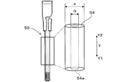
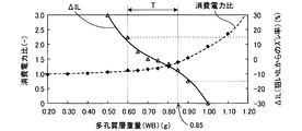
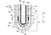
- FIG. 3 is a schematic diagram illustrating a configuration of a heater in the first embodiment. The figure showing the relationship between the weight of a porous layer in Example 1, power consumption ratio, and (DELTA) IL. The figure showing the relationship between the weight of a heater, generated stress, and power consumption ratio in Example 1. FIG. The figure showing the relationship between the outer diameter of a heater, the diameter of a hollow part, generated stress, and power consumption reduction rate in Example 1. FIG. Sectional drawing of the front end side of the gas sensor element in Example 2.
- FIG. 3 is a schematic diagram illustrating a configuration of a heater in the first embodiment. The figure showing the relationship between the weight of a porous layer in Example 1, power consumption ratio, and (DELTA) IL. The figure showing the relationship between the weight of a heater, generated stress, and power consumption ratio in Example 1.
- FIG. The figure showing the relationship between the outer diameter of a heater, the diameter of a hollow part, generated stress, and power consumption reduction rate in Example 1.
- the gas sensor element of the present disclosure can be used for air-fuel ratio control in an automobile internal combustion engine.
- the gas sensor element 1 of this example will be described with reference to FIGS.
- the gas sensor element 1 of this example is provided in a gas sensor 100 as shown in FIG.
- the gas sensor element 1 includes a solid electrolyte body 10, a measurement electrode 20, a reference electrode 30, a porous layer 40, and a heater 50.
- the solid electrolyte body 10 has an atmospheric chamber 11 inside, has a cup shape in which the distal end side Y1 is closed and the proximal end side Y2 is opened.
- the measurement electrode 20 is provided on the measured gas side wall surface 10 a facing the measured gas of the solid electrolyte body 10.
- the reference electrode 30 is provided on the reference gas side wall surface 10 b facing the atmospheric chamber 11 of the solid electrolyte body 10.
- the porous layer 40 is made of a porous material and is laminated on the measured gas side wall surface 10 a of the solid electrolyte body 10.
- the heater 50 is disposed in the atmosphere chamber 11 and is in contact with the bottom 11a of the atmosphere chamber 11, and has a heat generating portion 51 that generates heat when energized.
- the relationship of 0.07 ⁇ B / A ⁇ 1 is satisfied, where A is the length in the axial direction Y of the heat generating portion 51 and B is the length in the axial direction of the measuring electrode 20.
- the weight WB of the porous layer 40 is 0.60 g to 0.
- the weight WA of the heater 50 is 0.19 g to 0.25 g.
- the solid electrolyte body 10 is mainly composed of zirconia (ZrO 2 ). As shown in FIG. 2, the outer side surface of the solid electrolyte body 10 forms a measured gas side wall surface 10 a facing the measured gas, and the inner side surface of the solid electrolyte body 10 faces the reference gas side wall surface facing the atmospheric chamber 11. 10b.
- the measurement electrode 20 provided on the measured gas side wall surface 10a is formed on the entire circumference with a predetermined length in the axial direction Y at a position facing a heat generating portion 51 described later, and has a strip shape in the circumferential direction.
- the length B in the axial direction Y of the measurement electrode 20 can be set to 0.5 mm to 3.0 mm, for example.
- a signal lead portion (not shown) is formed on the outer surface of the solid electrolyte body 10 so as to extend from the measurement electrode 20 to the proximal end side Y2.
- the reference electrode 30 is formed on substantially the entire reference gas side wall surface 10 b of the solid electrolyte body 10.
- the bottom 11a of the atmospheric chamber 11 formed inside the cup-shaped solid electrolyte body 10 has a substantially hemispherical shape.
- the front end 53 of the heater 50 disposed in the atmospheric chamber 11 is in contact with the bottom 11 a of the atmospheric chamber 11.
- the heater 50 is a heater using a ceramic body such as alumina or silicon nitride, and includes a ceramic mandrel 54 and a ceramic sheet 55 wound around the mandrel 54.
- the mandrel 54 is formed in a cylindrical shape having a hollow portion 54 a extending in the axial direction Y. As shown in FIG.
- the ceramic sheet 55 is formed with a heat generating portion 51 made of a conductive paste containing tungsten and rhenium or molybdenum.
- the heat generating portion 51 is located on the distal end side Y1 of the mandrel 54.
- the heat generating part 51 is for heating the gas sensor element 1 to the activation temperature by generating heat by energization.
- the length A in the axial direction Y of the heat generating portion 51 can be set to, for example, 3.0 mm to 7.0 mm. Therefore, the length A in the axial direction Y of the heat generating portion 51 and the length B in the axial direction Y of the measurement electrode 20 satisfy the relationship of 0.07 ⁇ B / A ⁇ 1.
- the outer diameter of the mandrel 54 of the heater 50 is P and the diameter of the hollow portion 54a is Q
- P and Q satisfy the relationship 0.28 ⁇ Q / P ⁇ 0.6.
- the outer diameter P of the mandrel 54 can be 2.5 mm to 3.4 mm.
- the diameter Q of the hollow portion 54a can be set to 0.9 mm to 1.5 mm. The Q / P satisfies the above relationship.
- the porous layer 40 includes a diffusion resistance layer 41 laminated on the measured gas side wall surface 10 a of the solid electrolyte body 10, and a trap layer 42 laminated on the outer side of the diffusion resistance layer 41. And have.
- the diffusion resistance layer 41 is made of a gas-permeable alumina porous body, and the porosity and the like are set to a predetermined value so as to transmit the gas to be measured that is brought into contact with the measurement electrode 20.
- the trap layer 42 is made of a porous body that captures poisonous substances in the exhaust gas.
- the trap layer 42 has a porosity higher than that of the diffusion resistance layer 41, and is configured so as not to affect the diffusibility of the gas to be measured.
- the porous layer 40 is provided with a protective layer made of a porous material for ensuring water resistance between the diffusion resistance layer 41 and the trap layer 42. Further, a catalyst layer that purifies (combusts) H 2 and suppresses output deviation may be provided between the protective layer and the trap layer 42.
- the weight WB of the porous layer 40 in the region (tip region) S from the position 52 of 2 mm from the heat generating portion 51 to the proximal side Y2 to the distal side Y1 is set to 0.60 g to 0.85 g. it can. Further, the weight WA of the heater 50 in the tip region S can be 0.19 g to 0.25 g.
- the porous layer is thicker than the sensor element. Therefore, normally, the integrated power consumption in the A / F sensor element is larger than the integrated power consumption in the O 2 sensor element.
- the integrated power consumption ratio increases as the weight WB of the porous layer 40 increases.
- the rate of increase that is, the differential value of the curve indicating the integrated power consumption ratio
- the power consumption becomes excessive when the value exceeds 0.85 g.
- the change in the limit current output when the weight WB of the porous layer 40 in the tip region S was changed between 0.20 g and 1.10 g was verified.
- the current value obtained by measuring the weight WB of the porous layer 40 of the gas sensor element 1 in the atmosphere with the gas sensor element 1 having the reference weight as a predetermined reference weight is IL 0
- ⁇ IL represents a deviation from the target value
- ⁇ IL is an index of detection accuracy. If ⁇ IL exceeds ⁇ 15% which is an appropriate range, sufficient detection accuracy cannot be obtained, and ⁇ IL needs to be ⁇ 15% or less.
- ⁇ IL is ⁇ 15% or less.
- the weight WB of the porous layer 40 is 0.60 g to 0.85 g in the tip region S, the heat capacity of the gas sensor element 1 in the tip region S is excessively large. Therefore, an increase in power consumption of the heater 50 can be suppressed. Furthermore, since the weight WB of the porous layer 40 is within the above range, the output limit current can be set to an appropriate range, and thus the A / F detection accuracy is excellent.
- Power consumption ratio test 2 Regarding the gas sensor element 1 of this example, the power consumption when the weight WA of the heater 50 in the tip region S is changed between 0.10 g and 0.30 g, and the conventional cup-type O 2 sensor (power consumption ratio) The same power consumption as in Test 1 was compared. Specifically, as in the power consumption ratio test 1 described above, the integrated power consumption ratio in the gas sensor element 1 of this example was calculated. In order to achieve the effect of reducing power consumption, the cumulative power consumption ratio needs to be 1.0 or less. As shown in FIG. 5, when the weight WA of the heater 50 is 0.25 g or less, the integrated power consumption ratio in the gas sensor element 1 is 1.0 or less.
- the maximum stress generated by self-heating when the weight WA of the heater 50 in the tip region S was changed between 0.10 g and 0.30 g was verified. Specifically, by stress analysis simulation, the heater resistance of the heater 50 was set to 3 ⁇ , and the maximum stress generated in the heat generating part 51 when the heat generating part 51 reached 1000 ° C. by applying a voltage of 16 V to the heater 50 was calculated. . If the generated stress in the heater 50 exceeds 135 MPa, the heater 50 may be damaged by the generated stress. Therefore, the generated stress in the heater 50 needs to be 135 MPa or less. As shown in FIG. 5, when the weight WA of the heater 50 is 0.19 g or more, the generated stress in the heater 50 is shown to be 135 MPa or less.
- the weight WA of the heater 50 is 0.19 g to 0.25 g in the tip region S, power consumption can be suppressed and damage due to self-heating of the heater 50 is prevented. And excellent reliability.
- the maximum stress generated by self-heating when the diameter Q of the hollow portion 54a was changed with respect to the outer diameter P of the mandrel 54 of the heater 50 was verified.
- the heater resistance of the heater 50 is set to 3 ⁇ by the stress analysis simulation, and the heater 50 is heated to a temperature of 1000 ° C. by applying a voltage of 16V to the heater 50.
- the maximum stress generated at 50 was calculated. If the generated stress in the heater 50 exceeds 135 MPa, the heater 50 is damaged by the generated stress, and thus the generated stress in the heater 50 needs to be 135 MPa or less.
- the generated stress in the heater 50 is preferably 120 MPa or less. As shown in FIG. 6, it was shown that when Q / P is 0.6 or less, the generated stress in the heater 50 is 135 MPa or less. Furthermore, it was shown that when Q / P is 0.5 or less, the generated stress in the heater 50 is 120 MPa or less.
- P and Q must satisfy the range indicated by the arrow V in FIG. 6, that is, the relationship of 0.28 ⁇ Q / P ⁇ 0.6. confirmed. Furthermore, in order to further improve the reliability, it was confirmed that P and Q preferably satisfy the relationship of 0.28 ⁇ Q / P ⁇ 0.5.
- the outer diameter P of the heater 50 (the outer diameter of the mandrel 54) P and the inner diameter of the heater 50 (the diameter of the hollow portion 54a) Q are 0.28 ⁇ Q / P ⁇ 0.6. Since the relationship is satisfied, the gas sensor element 1 can suppress power consumption, and the heater 50 is prevented from being damaged due to self-heating, and thus has excellent reliability.
- the gas sensor element 1 can be incorporated in, for example, a rear gas sensor installed downstream of the catalyst filter in the exhaust system of the internal combustion engine. That is, the gas sensor 100 incorporating the gas sensor element 1 can be disposed on the downstream side of the catalyst filter that purifies the exhaust gas in the exhaust system of the automobile engine. In this case, a limit current depending on the oxygen concentration in the exhaust gas after passing through the catalyst filter is output. The air-fuel ratio in the air-fuel mixture supplied to the internal combustion engine can be calculated based on the obtained limit current and fed back to the engine control system.
- the gas sensor element 1 of the present invention is not limited to this, and can be used in various modes.
- the gas sensor element 1 that requires less power consumption, is excellent in A / F detection accuracy, and has high reliability.
- the gas sensor element 1 of this example includes an outer peripheral surface 50 a of the heater 50 and an inner peripheral surface of the atmospheric chamber 11 (that is, the reference electrode 30 laminated on the reference gas side wall surface 10 b of the solid electrolyte body 10). Between the two, a porous filling layer 60 filled with a porous material is formed.
- symbol is attached
- the porous filling layer 60 is made of the same kind of alumina (spinel) material as the forming material of the porous layer 40. Thereby, the heat generated from the heat generating portion 51 of the heater 50 is efficiently transmitted to the solid electrolyte body 10 through the porous filling layer 60, which contributes to reduction of power consumption. Note that the gas sensor element 1 of this example also provides the same operational effects as in the case of the first embodiment.
Landscapes
- Chemical & Material Sciences (AREA)
- Life Sciences & Earth Sciences (AREA)
- Health & Medical Sciences (AREA)
- Physics & Mathematics (AREA)
- Chemical Kinetics & Catalysis (AREA)
- Electrochemistry (AREA)
- Molecular Biology (AREA)
- Analytical Chemistry (AREA)
- Biochemistry (AREA)
- General Health & Medical Sciences (AREA)
- General Physics & Mathematics (AREA)
- Immunology (AREA)
- Pathology (AREA)
- Measuring Oxygen Concentration In Cells (AREA)
Abstract
消費電力が少なくて済むとともに、A/Fの検出精度に優れるガスセンサ素子を提供する。ガスセンサ素子1は、コップ型の固体電解質体10、測定電極20、基準電極30、及び多孔質層40を有する。そして、固体電解質体10の内側の大気室11には、その底部11aに接触するようにヒータ50が配設されている。ヒータ50の発熱部51の軸方向Yの長さをAとし、測定電極20の軸方向Yの長さをBとしたとき、0.07≦B/A≦1の関係を満たしている。そして、発熱部51より基端側Y2へ2mmの位置から先端側の領域Sにおいて、多孔質層40の重量WBが0.60g~0.85gであるとともに、ヒータ50の重量WAが0.19g~0.25gである。
Description
本開示は、ガスセンサ素子に関する。
本出願は、2014年6月30日にされた日本出願番号2014-133484号に基づくもので、ここにその記載内容を援用する。
従来、自動車等の内燃機関における空燃比制御のために、排ガス中の被測定ガス中の特定ガス濃度を検出するガスセンサが用いられている。このようなガスセンサに備えられている素子として、特許文献1には、有底円筒状の固体電解質体と固体電解質体の外周面及び内周面に設けられた一対の電極と、固体電解質体の外周面側に積層される多孔質層と、を備えるいわゆるコップ型のO2センサ素子が開示されている。
近年の低エミッション化の要請に応じて、排ガス浄化用触媒の下流(リア環境)に空燃比(A/F)を検出するA/Fセンサを設けることにより、空燃比制御の精度向上が図られている。A/Fセンサは高温下で使用する必要があるため、A/Fセンサには電極を加熱するヒータが備えられている。そして、かかるリア環境では、A/Fセンサに対する被水量が増加しやすいことから、当該A/Fセンサの信頼性を高めるためには、センサ素子の外周に設けられる多孔質層の厚さを大きくすることが考えられる。しかしながら、多孔質層を肉厚にすると素子全体の熱容量が増加して、ヒータの消費電力量が増加することとなる。これは燃費の低下を招く要因の一つとなるため、好ましくない。また、限界電流によりA/Fを検出するA/Fセンサでは、排ガス中の酸素濃度、HCやNOXなどの他のガス成分濃度によって、出力される限界電流が変化することから、多孔質層の厚さを変化させると、出力される限界電流が変化することとなる。したがって、多孔質層の厚さを過度に大きく又は小さくすると、出力される限界電流が適正な範囲を超えてしまう。そして、限界電流を検出してA/Fを検出するA/Fセンサでは、限界電流が適正な範囲を超えると、A/Fの十分な検出精度が得られないという問題が生じる。一方、ヒータの消費電力を低減するには、ヒータの重量を削減してその熱容量を低減させることが考えられる。しかし、ヒータの重量を過度に削減すれば、ヒータの発熱に応じて生じるヒータの応力が過度に上昇することによってヒータが破損するおそれがあることから、信頼性が低下するという問題がある。
本開示は、かかる背景に鑑みてなされたもので、消費電力が少なくて済むとともに、A/Fの検出精度に優れ、高い信頼性が得られるガスセンサ素子を提供しようとするものである。
本開示の一態様は、内部に大気室を設けると共に先端側が閉塞され、基端側が開口されたコップ型の固体電解質体と、該固体電解質体の被測定ガスと対面する被測定ガス側壁面に設けられた測定電極と、上記大気室と対面する基準ガス側壁面に設けられた基準電極と、上記固体電解質体における上記被測定ガス側壁面に積層された多孔質からなる多孔質層と、上記大気室に配設されて上記大気室の底部に接触しているとともに、通電により発熱する発熱部を有するヒータと、を備え、上記発熱部の軸方向の長さをAとし、上記測定電極の軸方向の長さをBとしたとき、0.07≦B/A≦1の関係を満たすとともに、上記発熱部より基端側へ2mmの位置から先端側の領域において、上記多孔質層の重量が0.60g~0.85gであるとともに、上記ヒータの重量が0.19g~0.25gであることを特徴とするガスセンサ素子にある。
上記ガスセンサ素子においては、発熱部より基端側へ2mmの位置から先端側の領域において、多孔質層の重量が0.60g~0.85gとなっている。これにより、当該領域における素子の熱容量が過度に大きくなることが防止されるため、ヒータの消費電力の増加を抑制することができる。さらに、多孔質層の重量が上記範囲内であるため、出力される限界電流を適正な範囲とすることができることから、A/Fの検出精度に優れる。また、当該領域において、ヒータの重量が0.19g~0.25gとなっていることから、消費電力を抑制できるとともに、ヒータの自己発熱による破損が防止されて信頼性に優れる。
以上のごとく、本開示によれば、消費電力が少なくて済むとともに、A/Fの検出精度に優れ、高い信頼性が得られるガスセンサ素子を提供することができる。
本開示のガスセンサ素子は、自動車の内燃機関における空燃比制御に使用することができる。
(実施例1)
本例のガスセンサ素子1につき、図1~図6を用いて説明する。
本例のガスセンサ素子1は、図1に示すように、ガスセンサ100に備えられている。
ガスセンサ素子1は、図2に示すように、固体電解質体10、測定電極20、基準電極30、多孔質層40、及びヒータ50を備える。
固体電解質体10は、内部に大気室11を有すると共に先端側Y1が閉塞され、基端側Y2が開口されたコップ型を成している。
測定電極20は、固体電解質体10の被測定ガスと対面する被測定ガス側壁面10aに設けられている。
基準電極30は、固体電解質体10の大気室11と対面する基準ガス側壁面10bに設けられている。
多孔質層40は、多孔質からなり、固体電解質体10における被測定ガス側壁面10aに積層されている。
ヒータ50は、大気室11に配設されて大気室11の底部11aに接触しているとともに、通電により発熱する発熱部51を有する。
そして、発熱部51の軸方向Yの長さをAとし、測定電極20の軸方向の長さをBとしたとき、0.07≦B/A≦1の関係を満たす。また、軸方向Yにおける発熱部51より基端側Y2へ2mmの位置52から先端側の領域(以下、「先端領域S」ともいう)において、多孔質層40の重量WBが0.60g~0.85gであるとともに、ヒータ50の重量WAが0.19g~0.25gである。なお、本開示において、数値範囲の指定に「~」を用いたとき、特に定義する場合を除き、境界の数値はその範囲に含まれる。
本例のガスセンサ素子1につき、図1~図6を用いて説明する。
本例のガスセンサ素子1は、図1に示すように、ガスセンサ100に備えられている。
ガスセンサ素子1は、図2に示すように、固体電解質体10、測定電極20、基準電極30、多孔質層40、及びヒータ50を備える。
固体電解質体10は、内部に大気室11を有すると共に先端側Y1が閉塞され、基端側Y2が開口されたコップ型を成している。
測定電極20は、固体電解質体10の被測定ガスと対面する被測定ガス側壁面10aに設けられている。
基準電極30は、固体電解質体10の大気室11と対面する基準ガス側壁面10bに設けられている。
多孔質層40は、多孔質からなり、固体電解質体10における被測定ガス側壁面10aに積層されている。
ヒータ50は、大気室11に配設されて大気室11の底部11aに接触しているとともに、通電により発熱する発熱部51を有する。
そして、発熱部51の軸方向Yの長さをAとし、測定電極20の軸方向の長さをBとしたとき、0.07≦B/A≦1の関係を満たす。また、軸方向Yにおける発熱部51より基端側Y2へ2mmの位置52から先端側の領域(以下、「先端領域S」ともいう)において、多孔質層40の重量WBが0.60g~0.85gであるとともに、ヒータ50の重量WAが0.19g~0.25gである。なお、本開示において、数値範囲の指定に「~」を用いたとき、特に定義する場合を除き、境界の数値はその範囲に含まれる。
以下、本例のガスセンサ素子1について、詳述する。
固体電解質体10は、ジルコニア(ZrO2)を主成分としてなる。図2に示すように、固体電解質体10の外側面は被測定ガスと対面する被測定ガス側壁面10aをなしており、固体電解質体10の内側面は大気室11と対面する基準ガス側壁面10bをなしている。被測定ガス側壁面10aに設けられる測定電極20は後述の発熱部51に対向する位置において軸方向Yに所定の長さで全周に形成されており、周方向に帯状をなしている。測定電極20の軸方向Yにおける長さBは、例えば、0.5mm~3.0mmとすることができる。そして、測定電極20から基端側Y2へ延びるように、固体電解質体10の外側面に信号リード部(図示せず)が形成されている。一方、基準電極30は、固体電解質体10の基準ガス側壁面10bの略全面に形成されている。
固体電解質体10は、ジルコニア(ZrO2)を主成分としてなる。図2に示すように、固体電解質体10の外側面は被測定ガスと対面する被測定ガス側壁面10aをなしており、固体電解質体10の内側面は大気室11と対面する基準ガス側壁面10bをなしている。被測定ガス側壁面10aに設けられる測定電極20は後述の発熱部51に対向する位置において軸方向Yに所定の長さで全周に形成されており、周方向に帯状をなしている。測定電極20の軸方向Yにおける長さBは、例えば、0.5mm~3.0mmとすることができる。そして、測定電極20から基端側Y2へ延びるように、固体電解質体10の外側面に信号リード部(図示せず)が形成されている。一方、基準電極30は、固体電解質体10の基準ガス側壁面10bの略全面に形成されている。
コップ型の固体電解質体10の内側に形成される大気室11の底部11aは、略半球面状となっている。大気室11に配置されるヒータ50は、その先端53が大気室11の底部11aに接触している。ヒータ50は、アルミナ、窒化ケイ素等の磁器体を用いたヒータであって、セラミック製の心棒54と、心棒54の周囲に巻回されたセラミックシート55とを有する。心棒54は、図3に示すように、軸方向Yに延びる中空部54aを有する円筒状に形成されている。図2に示すように、セラミックシート55には、タングステンとレニウムもしくは、モリブデンを含有する導電性ペーストよりなる発熱部51が形成されている。発熱部51は心棒54の先端側Y1に位置している。発熱部51は、通電によって発熱することにより、ガスセンサ素子1を活性温度まで加熱するためのものである。発熱部51の軸方向Yの長さAは、例えば、3.0mm~7.0mmとすることができる。したがって、発熱部51の軸方向Yの長さAと、測定電極20の軸方向Yの長さBとは、0.07≦B/A≦1の関係を満たしている。
図3に示すように、ヒータ50の心棒54の外径をPとし、中空部54aの径をQとしたとき、PとQは0.28<Q/P≦0.6の関係を満たしている。例えば、心棒54の外径Pは2.5mm~3.4mmとすることができる。また、中空部54aの径Qは0.9mm~1.5mmとすることができる。そして、当該Q/Pは上記関係を満たしている。
図2に示すように、多孔質層40は、固体電解質体10の被測定ガス側壁面10aに積層されてなる拡散抵抗層41と、拡散抵抗層41のさらに外側に積層されてなるトラップ層42とを有する。拡散抵抗層41はガス透過性のアルミナ多孔体からなり、測定電極20に接触させる被測定ガスを透過するように気孔率等が所定の値に設定されている。トラップ層42は排ガス中の被毒物を捕獲する多孔質体からなる。トラップ層42は拡散抵抗層41の気孔率よりも高い気孔率を有しており、被測定ガスの拡散性に影響を及ぼさないように構成されている。
なお、図示しないが多孔質層40には、拡散抵抗層41とトラップ層42との間に、耐被水性を確保するための多孔質体からなる保護層が備えられている。また、保護層とトラップ層42との間に、H2を浄化(燃焼)させて、出力ズレを抑制する触媒層を備えていてもよい。
ガスセンサ素子1において、発熱部51より基端側Y2へ2mmの位置52から先端側Y1の領域(先端領域)Sにおける多孔質層40の重量WBは、0.60g~0.85gとすることができる。また、先端領域Sにおけるヒータ50の重量WAは、0.19g~0.25gとすることができる。
(消費電力比試験1)
本例のガスセンサ素子1について、先端領域Sにおける多孔質層40の重量WBを0.20g~1.10gの間で変更したときの消費電力と、従来品であるコップ型のO2センサ素子(株式会社デンソー社製、型番150200-3000)の消費電力とを比較した。具体的には、走行モードLA#4における積算消費電力について、上記従来品における積算消費電力を1として、本例のガスセンサ素子1における積算消費電力比を算出した。A/Fセンサ素子は、限界電流を検出させるために被測定ガスの拡散を制限する所定の厚さの拡散抵抗層を多孔質層として備えていることから、当該拡散抵抗層を要しないO2センサ素子に比べて、多孔質層が厚くなる。そのため、通常、A/Fセンサ素子における積算消費電力は、O2センサ素子における積算消費電力に比べて多くなる。図4に示すように、多孔質層40の重量WBが増加するのにしたがって、上記積算消費電力比は増加している。そして、多孔質層40の重量WBが0.85gを超えるとその増加率(すなわち、積算消費電力比を示す曲線の微分値)が急激に上昇していることから、多孔質層40の重量WBが0.85gを超えると、消費電力が過剰となることが示された。
本例のガスセンサ素子1について、先端領域Sにおける多孔質層40の重量WBを0.20g~1.10gの間で変更したときの消費電力と、従来品であるコップ型のO2センサ素子(株式会社デンソー社製、型番150200-3000)の消費電力とを比較した。具体的には、走行モードLA#4における積算消費電力について、上記従来品における積算消費電力を1として、本例のガスセンサ素子1における積算消費電力比を算出した。A/Fセンサ素子は、限界電流を検出させるために被測定ガスの拡散を制限する所定の厚さの拡散抵抗層を多孔質層として備えていることから、当該拡散抵抗層を要しないO2センサ素子に比べて、多孔質層が厚くなる。そのため、通常、A/Fセンサ素子における積算消費電力は、O2センサ素子における積算消費電力に比べて多くなる。図4に示すように、多孔質層40の重量WBが増加するのにしたがって、上記積算消費電力比は増加している。そして、多孔質層40の重量WBが0.85gを超えるとその増加率(すなわち、積算消費電力比を示す曲線の微分値)が急激に上昇していることから、多孔質層40の重量WBが0.85gを超えると、消費電力が過剰となることが示された。
(限界電流試験)
本例のガスセンサ素子1において、先端領域Sにおける多孔質層40の重量WBを0.20g~1.10gの間で変更したときの出力される限界電流の変化について検証をした。具体的には、ガスセンサ素子1の多孔質層40の重量WBを所定の基準重量として当該基準重量のガスセンサ素子1により大気中で測定して得られた電流値をIL0とし、多孔質層40の重量WBを上述の如く変化させて大気中で測定して得られた電流値をIL1として、両者の変化率ΔIL(%)=(IL1-IL0)/IL0×100を算出した。すなわち、ΔILは、狙い値からのズレを表すものであって、ΔILは検出精度の指標となる。そして、ΔILが適正な範囲である±15%を超えると、十分な検出精度が得られないことから、ΔILは±15%以下であることを要する。図4に示すように、本例のガスセンサ素子1においては、多孔質層40の重量WBが0.60g以上0.90g以下であれば、ΔILが±15%以下となることが示された。
本例のガスセンサ素子1において、先端領域Sにおける多孔質層40の重量WBを0.20g~1.10gの間で変更したときの出力される限界電流の変化について検証をした。具体的には、ガスセンサ素子1の多孔質層40の重量WBを所定の基準重量として当該基準重量のガスセンサ素子1により大気中で測定して得られた電流値をIL0とし、多孔質層40の重量WBを上述の如く変化させて大気中で測定して得られた電流値をIL1として、両者の変化率ΔIL(%)=(IL1-IL0)/IL0×100を算出した。すなわち、ΔILは、狙い値からのズレを表すものであって、ΔILは検出精度の指標となる。そして、ΔILが適正な範囲である±15%を超えると、十分な検出精度が得られないことから、ΔILは±15%以下であることを要する。図4に示すように、本例のガスセンサ素子1においては、多孔質層40の重量WBが0.60g以上0.90g以下であれば、ΔILが±15%以下となることが示された。
以上の消費電力比試験1及び限界電流試験の結果から、多孔質層40の重量WBは図4において矢印Tで示す範囲、すなわち、0.60g~0.85gであることを要することが確認された。
本例のガスセンサ素子1によれば、先端領域Sにおいて、多孔質層40の重量WBが0.60g~0.85gとなっていることから、先端領域Sにおけるガスセンサ素子1の熱容量が過度に大きくなることが防止されるため、ヒータ50の消費電力の増加を抑制することができる。さらに、多孔質層40の重量WBが上記範囲内であるため、出力される限界電流を適正な範囲とすることができることから、A/Fの検出精度に優れる。
(消費電力比試験2)
本例のガスセンサ素子1について、先端領域Sにおけるヒータ50の重量WAを0.10g~0.30gの間で変更したときの消費電力と、従来品であるコップ型のO2センサ(消費電力比試験1の場合と同一もの)の消費電力とを比較した。具体的には、上述の消費電力比試験1と同様に、本例のガスセンサ素子1における積算消費電力比を算出した。消費電力の低減効果を奏するには、当該積算消費電力比は1.0以下であることを要する。図5に示すように、ヒータ50の重量WAが0.25g以下であれば、ガスセンサ素子1における積算消費電力比が1.0以下となることが示された。
本例のガスセンサ素子1について、先端領域Sにおけるヒータ50の重量WAを0.10g~0.30gの間で変更したときの消費電力と、従来品であるコップ型のO2センサ(消費電力比試験1の場合と同一もの)の消費電力とを比較した。具体的には、上述の消費電力比試験1と同様に、本例のガスセンサ素子1における積算消費電力比を算出した。消費電力の低減効果を奏するには、当該積算消費電力比は1.0以下であることを要する。図5に示すように、ヒータ50の重量WAが0.25g以下であれば、ガスセンサ素子1における積算消費電力比が1.0以下となることが示された。
(発生応力試験1)
本例のガスセンサ素子1について、先端領域Sにおけるヒータ50の重量WAを0.10g~0.30gの間で変更したときの自己発熱による最大発生応力を検証した。具体的は、応力解析シミュレーションにより、ヒータ50のヒータ抵抗を3Ωとし、かかるヒータ50に16Vの電圧を印加して発熱部51が1000℃に到達したときの発熱部51の最大発生応力を算出した。ヒータ50における発生応力が135MPaを超えると、ヒータ50は当該発生応力により破損するおそれがあるため、ヒータ50における発生応力は135MPa以下であることを要する。図5に示すように、ヒータ50の重量WAが0.19g以上であれば、ヒータ50における発生応力は135MPa以下となることが示された。
本例のガスセンサ素子1について、先端領域Sにおけるヒータ50の重量WAを0.10g~0.30gの間で変更したときの自己発熱による最大発生応力を検証した。具体的は、応力解析シミュレーションにより、ヒータ50のヒータ抵抗を3Ωとし、かかるヒータ50に16Vの電圧を印加して発熱部51が1000℃に到達したときの発熱部51の最大発生応力を算出した。ヒータ50における発生応力が135MPaを超えると、ヒータ50は当該発生応力により破損するおそれがあるため、ヒータ50における発生応力は135MPa以下であることを要する。図5に示すように、ヒータ50の重量WAが0.19g以上であれば、ヒータ50における発生応力は135MPa以下となることが示された。
以上の消費電力比試験2及び発生応力試験1の結果から、ヒータ50の重量WAは図5において矢印Uで示す範囲、すなわち、0.19g~0.25gであることを要することが確認された。
本例のガスセンサ素子1では、先端領域Sにおいて、ヒータ50の重量WAが0.19g~0.25gとなっていることから、消費電力を抑制できるとともに、ヒータ50の自己発熱による破損が防止されて信頼性に優れる。
(消費電力低減試験)
本例のガスセンサ素子1について、ヒータ50の心棒54の外径Pに対して中空部54aの径Qを変更させたときの消費電力の低減率について試験を行った。具体的には、Q/P=0であるとき、すなわち、中空部54aが形成されていない状態の消費電力量V0を基準として、当該Q/Pを0~0.63まで変化させたときのガスセンサ素子1の消費電力量V1を測定し、(V0-V1)/V0×100により消費電力低減率(%)を算出した。当該消費電力の低減効果が確実に発揮されるために、消費電力低減率は1.0%以上であることを要する。図6に示すように、ガスセンサ素子1における消費電力低減率は、Q/Pが0.28より大きれば消費電力低減率が1.0%よりも大きくなることが示された。
本例のガスセンサ素子1について、ヒータ50の心棒54の外径Pに対して中空部54aの径Qを変更させたときの消費電力の低減率について試験を行った。具体的には、Q/P=0であるとき、すなわち、中空部54aが形成されていない状態の消費電力量V0を基準として、当該Q/Pを0~0.63まで変化させたときのガスセンサ素子1の消費電力量V1を測定し、(V0-V1)/V0×100により消費電力低減率(%)を算出した。当該消費電力の低減効果が確実に発揮されるために、消費電力低減率は1.0%以上であることを要する。図6に示すように、ガスセンサ素子1における消費電力低減率は、Q/Pが0.28より大きれば消費電力低減率が1.0%よりも大きくなることが示された。
(発生応力試験2)
本例のガスセンサ素子1について、ヒータ50の心棒54の外径Pに対して中空部54aの径Qを変更させたときの自己発熱による最大発生応力を検証した。具体的には、発生応力試験1と同様に、応力解析シミュレーションにより、ヒータ50のヒータ抵抗を3Ωとし、かかるヒータ50に16Vの電圧を印加して発熱部51が1000℃に到達したときのヒータ50における最大発生応力を算出した。ヒータ50における発生応力が135MPaを超えると、ヒータ50は当該発生応力により破損するため、ヒータ50における発生応力は135MPa以下であることを要する。さらに信頼性を一層向上させるためには、ヒータ50における発生応力は120MPa以下であることが好ましい。図6に示すように、Q/Pが0.6以下であれば、ヒータ50における発生応力は135MPa以下となることが示された。さらに、Q/Pが0.5以下であれば、ヒータ50における発生応力は120MPa以下となることが示された。
本例のガスセンサ素子1について、ヒータ50の心棒54の外径Pに対して中空部54aの径Qを変更させたときの自己発熱による最大発生応力を検証した。具体的には、発生応力試験1と同様に、応力解析シミュレーションにより、ヒータ50のヒータ抵抗を3Ωとし、かかるヒータ50に16Vの電圧を印加して発熱部51が1000℃に到達したときのヒータ50における最大発生応力を算出した。ヒータ50における発生応力が135MPaを超えると、ヒータ50は当該発生応力により破損するため、ヒータ50における発生応力は135MPa以下であることを要する。さらに信頼性を一層向上させるためには、ヒータ50における発生応力は120MPa以下であることが好ましい。図6に示すように、Q/Pが0.6以下であれば、ヒータ50における発生応力は135MPa以下となることが示された。さらに、Q/Pが0.5以下であれば、ヒータ50における発生応力は120MPa以下となることが示された。
以上の消費電力低減試験及び発生応力試験2の結果から、P及びQは図6において矢印Vで示す範囲、すなわち、0.28<Q/P≦0.6の関係を満たすことを要することが確認された。さらに、信頼性を一層向上させるためには、P及びQが0.28<Q/P≦0.5の関係を満たすことが好ましいことが確認された。
本例のガスセンサ素子1は、ヒータ50の外径(心棒54の外径)Pと、ヒータ50の内径(中空部54aの径)Qとが、0.28<Q/P≦0.6の関係を満たしているため、ガスセンサ素子1は消費電力を抑制できるとともに、ヒータ50の自己発熱による破損が防止されて信頼性に優れる。
なお、ガスセンサ素子1は、例えば、内燃機関の排気系における触媒フィルタよりも下流側に設置されるリア用ガスセンサに内蔵されるものとすることができる。すなわち、ガスセンサ素子1を内蔵したガスセンサ100は、自動車エンジンの排気系において、排ガスを浄化する触媒フィルタの下流側に配置されるものとすることができる。この場合、触媒フィルタを通過した後の排ガス中の酸素濃度に依存した限界電流を出力する。そして、得られた限界電流に基づいて、内燃機関に供給された混合気における空燃比を算出して、エンジン制御システムにフィードバックするよう構成することができる。ただし、本発明のガスセンサ素子1は、これに限定されるものではなく、種々の態様にて使用することができる。
以上のごとく、本例によれば、消費電力が少なくて済むとともに、A/Fの検出精度に優れ、高い信頼性が得られるガスセンサ素子1を提供することができる。
(実施例2)
本例のガスセンサ素子1は、図7に示すように、ヒータ50の外周面50aと大気室11の内周面(すなわち、固体電解質体10の基準ガス側壁面10bに積層された基準電極30)との間には、多孔質が充填されてなる多孔質充填層60が形成されている。なお、実施例1の場合と同一の構成要素には、同一の符号を付してその説明を省略する。
本例のガスセンサ素子1は、図7に示すように、ヒータ50の外周面50aと大気室11の内周面(すなわち、固体電解質体10の基準ガス側壁面10bに積層された基準電極30)との間には、多孔質が充填されてなる多孔質充填層60が形成されている。なお、実施例1の場合と同一の構成要素には、同一の符号を付してその説明を省略する。
多孔質充填層60は、多孔質層40の形成材料と同種のアルミナ(スピネル)材料からなる。これにより、多孔質充填層60を介して、ヒータ50の発熱部51から生じた熱が固体電解質体10へ効率的に伝達されることから消費電力の低減に寄与する。なお、本例のガスセンサ素子1によっても、実施例1の場合と同等の作用効果を奏する。
1 ガスセンサ素子
10 固体電解質体
10a 被測定ガス側壁面
10b 基準ガス側壁面
11 大気室
20 測定電極
30 基準電極
40 多孔質層
50 ヒータ
51 発熱部
60 多孔質充填層
10 固体電解質体
10a 被測定ガス側壁面
10b 基準ガス側壁面
11 大気室
20 測定電極
30 基準電極
40 多孔質層
50 ヒータ
51 発熱部
60 多孔質充填層
Claims (3)
- 内部に大気室(11)を設けると共に先端側(Y1)が閉塞され、基端側(Y2)が開口されたコップ型の固体電解質体(10)と、
該固体電解質体(10)の被測定ガスと対面する被測定ガス側壁面(10a)に設けられた測定電極(20)と、
上記大気室(11)と対面する基準ガス側壁面(10b)に設けられた基準電極(30)と、
上記固体電解質体(10)における上記被測定ガス側壁面(10a)に積層された多孔質からなる多孔質層(40)と、
上記大気室(11)に配設されて上記大気室(11)の底部(11a)に接触しているとともに、通電により発熱する発熱部(51)を有するヒータ(50)と、を備え、
上記発熱部(51)の軸方向(Y)の長さをAとし、上記測定電極(20)の軸方向(Y)の長さをBとしたとき、0.07≦B/A≦1の関係を満たすとともに、
上記発熱部(51)より基端側(Y2)へ2mmの位置から先端側(Y1)の領域(S)において、上記多孔質層(40)の重量(WB)が0.60g~0.85gであるとともに、上記ヒータ(50)の重量(WA)が0.19g~0.25gであることを特徴とするガスセンサ素子(1)。 - 上記ヒータ(50)は中空の筒状に形成されており、上記ヒータ(50)の外径をPとし、上記ヒータ(50)の内径をQとしたとき、0.28<Q/P≦0.6の関係を満たすことを特徴とする請求項1に記載のガスセンサ素子(1)。
- 上記ヒータ(50)の外周面(50a)と上記大気室(11)の内周面との間には、多孔質が充填されてなる多孔質充填層(60)が形成されていることを特徴とする請求項1又は2に記載のガスセンサ素子(1)。
Applications Claiming Priority (2)
| Application Number | Priority Date | Filing Date | Title |
|---|---|---|---|
| JP2014133484A JP6476607B2 (ja) | 2014-06-30 | 2014-06-30 | ガスセンサ素子 |
| JP2014-133484 | 2014-06-30 |
Publications (1)
| Publication Number | Publication Date |
|---|---|
| WO2016002735A1 true WO2016002735A1 (ja) | 2016-01-07 |
Family
ID=55019267
Family Applications (1)
| Application Number | Title | Priority Date | Filing Date |
|---|---|---|---|
| PCT/JP2015/068733 Ceased WO2016002735A1 (ja) | 2014-06-30 | 2015-06-29 | ガスセンサ素子 |
Country Status (2)
| Country | Link |
|---|---|
| JP (1) | JP6476607B2 (ja) |
| WO (1) | WO2016002735A1 (ja) |
Families Citing this family (2)
| Publication number | Priority date | Publication date | Assignee | Title |
|---|---|---|---|---|
| JP6740922B2 (ja) | 2017-02-02 | 2020-08-19 | 株式会社デンソー | ガスセンサ |
| JP6740921B2 (ja) | 2017-02-02 | 2020-08-19 | 株式会社デンソー | ガスセンサ |
Citations (8)
| Publication number | Priority date | Publication date | Assignee | Title |
|---|---|---|---|---|
| JPS57192856A (en) * | 1981-05-25 | 1982-11-27 | Ngk Insulators Ltd | Oxygen concentration detector |
| JPH08271474A (ja) * | 1995-02-01 | 1996-10-18 | Nippondenso Co Ltd | 酸素濃度検出器 |
| JPH09203718A (ja) * | 1996-01-25 | 1997-08-05 | Denso Corp | ヒータ付空燃比センサの組付方法 |
| JP2001257059A (ja) * | 2000-03-13 | 2001-09-21 | Ibiden Co Ltd | セラミックヒーター |
| JP2002031618A (ja) * | 2000-05-12 | 2002-01-31 | Denso Corp | ガスセンサ |
| JP2003294695A (ja) * | 2002-03-29 | 2003-10-15 | Hitachi Unisia Automotive Ltd | 空燃比検出装置 |
| JP2012093377A (ja) * | 2007-02-05 | 2012-05-17 | Ngk Spark Plug Co Ltd | ガスセンサとその製造方法 |
| JP2015111099A (ja) * | 2013-11-06 | 2015-06-18 | 日本特殊陶業株式会社 | ヒータ及びガスセンサ |
-
2014
- 2014-06-30 JP JP2014133484A patent/JP6476607B2/ja active Active
-
2015
- 2015-06-29 WO PCT/JP2015/068733 patent/WO2016002735A1/ja not_active Ceased
Patent Citations (8)
| Publication number | Priority date | Publication date | Assignee | Title |
|---|---|---|---|---|
| JPS57192856A (en) * | 1981-05-25 | 1982-11-27 | Ngk Insulators Ltd | Oxygen concentration detector |
| JPH08271474A (ja) * | 1995-02-01 | 1996-10-18 | Nippondenso Co Ltd | 酸素濃度検出器 |
| JPH09203718A (ja) * | 1996-01-25 | 1997-08-05 | Denso Corp | ヒータ付空燃比センサの組付方法 |
| JP2001257059A (ja) * | 2000-03-13 | 2001-09-21 | Ibiden Co Ltd | セラミックヒーター |
| JP2002031618A (ja) * | 2000-05-12 | 2002-01-31 | Denso Corp | ガスセンサ |
| JP2003294695A (ja) * | 2002-03-29 | 2003-10-15 | Hitachi Unisia Automotive Ltd | 空燃比検出装置 |
| JP2012093377A (ja) * | 2007-02-05 | 2012-05-17 | Ngk Spark Plug Co Ltd | ガスセンサとその製造方法 |
| JP2015111099A (ja) * | 2013-11-06 | 2015-06-18 | 日本特殊陶業株式会社 | ヒータ及びガスセンサ |
Also Published As
| Publication number | Publication date |
|---|---|
| JP2016011885A (ja) | 2016-01-21 |
| JP6476607B2 (ja) | 2019-03-06 |
Similar Documents
| Publication | Publication Date | Title |
|---|---|---|
| JP5416686B2 (ja) | マルチガスセンサ | |
| JP5134399B2 (ja) | ガスセンサ及びガスセンサ制御装置 | |
| JP4981187B2 (ja) | NOxセンサの製造方法 | |
| CN111295583A (zh) | 气体传感器 | |
| JP5033017B2 (ja) | アンモニアガスセンサ | |
| JP6350326B2 (ja) | ガスセンサ | |
| JP5281988B2 (ja) | アンモニアガスセンサ | |
| JP2011047756A (ja) | アンモニアガスセンサ | |
| JP6233207B2 (ja) | ガスセンサ | |
| JP6476607B2 (ja) | ガスセンサ素子 | |
| CN105765377B (zh) | 氧传感器元件 | |
| CN108431589A (zh) | 用于检测测量气体空间中的测量气体的至少一种特性的传感器元件 | |
| JP7311992B2 (ja) | ガスセンサ及びセンサ素子 | |
| JP7229204B2 (ja) | センサ素子、ガスセンサ及びガスセンサユニット | |
| JP5977414B2 (ja) | ガスセンサ素子及びガスセンサ | |
| JP6480228B2 (ja) | ガスセンサ | |
| JP6943575B2 (ja) | ガスセンサ | |
| JP2009229352A (ja) | 酸素センサ | |
| JP6204252B2 (ja) | アンモニアガスセンサ | |
| JP2018185234A5 (ja) | ||
| JP6702342B2 (ja) | ガスセンサ | |
| JP2004239688A (ja) | 空燃比検出装置 | |
| JP2013053940A (ja) | アンモニアガスセンサ | |
| JP2019174147A (ja) | アンモニアセンサ素子、及びガスセンサ | |
| JP2005195368A (ja) | 酸素濃度検出制御装置 |
Legal Events
| Date | Code | Title | Description |
|---|---|---|---|
| 121 | Ep: the epo has been informed by wipo that ep was designated in this application |
Ref document number: 15815510 Country of ref document: EP Kind code of ref document: A1 |
|
| NENP | Non-entry into the national phase |
Ref country code: DE |
|
| 122 | Ep: pct application non-entry in european phase |
Ref document number: 15815510 Country of ref document: EP Kind code of ref document: A1 |