WO2016002685A1 - 車両制動装置 - Google Patents
車両制動装置 Download PDFInfo
- Publication number
- WO2016002685A1 WO2016002685A1 PCT/JP2015/068611 JP2015068611W WO2016002685A1 WO 2016002685 A1 WO2016002685 A1 WO 2016002685A1 JP 2015068611 W JP2015068611 W JP 2015068611W WO 2016002685 A1 WO2016002685 A1 WO 2016002685A1
- Authority
- WO
- WIPO (PCT)
- Prior art keywords
- vehicle
- speed
- braking
- force
- braking force
- Prior art date
- Legal status (The legal status is an assumption and is not a legal conclusion. Google has not performed a legal analysis and makes no representation as to the accuracy of the status listed.)
- Ceased
Links
Images



Classifications
-
- B—PERFORMING OPERATIONS; TRANSPORTING
- B60—VEHICLES IN GENERAL
- B60T—VEHICLE BRAKE CONTROL SYSTEMS OR PARTS THEREOF; BRAKE CONTROL SYSTEMS OR PARTS THEREOF, IN GENERAL; ARRANGEMENT OF BRAKING ELEMENTS ON VEHICLES IN GENERAL; PORTABLE DEVICES FOR PREVENTING UNWANTED MOVEMENT OF VEHICLES; VEHICLE MODIFICATIONS TO FACILITATE COOLING OF BRAKES
- B60T8/00—Arrangements for adjusting wheel-braking force to meet varying vehicular or ground-surface conditions, e.g. limiting or varying distribution of braking force
- B60T8/32—Arrangements for adjusting wheel-braking force to meet varying vehicular or ground-surface conditions, e.g. limiting or varying distribution of braking force responsive to a speed condition, e.g. acceleration or deceleration
- B60T8/58—Arrangements for adjusting wheel-braking force to meet varying vehicular or ground-surface conditions, e.g. limiting or varying distribution of braking force responsive to a speed condition, e.g. acceleration or deceleration responsive to speed and another condition or to plural speed conditions
-
- B—PERFORMING OPERATIONS; TRANSPORTING
- B60—VEHICLES IN GENERAL
- B60T—VEHICLE BRAKE CONTROL SYSTEMS OR PARTS THEREOF; BRAKE CONTROL SYSTEMS OR PARTS THEREOF, IN GENERAL; ARRANGEMENT OF BRAKING ELEMENTS ON VEHICLES IN GENERAL; PORTABLE DEVICES FOR PREVENTING UNWANTED MOVEMENT OF VEHICLES; VEHICLE MODIFICATIONS TO FACILITATE COOLING OF BRAKES
- B60T1/00—Arrangements of braking elements, i.e. of those parts where braking effect occurs specially for vehicles
- B60T1/02—Arrangements of braking elements, i.e. of those parts where braking effect occurs specially for vehicles acting by retarding wheels
- B60T1/10—Arrangements of braking elements, i.e. of those parts where braking effect occurs specially for vehicles acting by retarding wheels by utilising wheel movement for accumulating energy, e.g. driving air compressors
-
- B—PERFORMING OPERATIONS; TRANSPORTING
- B60—VEHICLES IN GENERAL
- B60T—VEHICLE BRAKE CONTROL SYSTEMS OR PARTS THEREOF; BRAKE CONTROL SYSTEMS OR PARTS THEREOF, IN GENERAL; ARRANGEMENT OF BRAKING ELEMENTS ON VEHICLES IN GENERAL; PORTABLE DEVICES FOR PREVENTING UNWANTED MOVEMENT OF VEHICLES; VEHICLE MODIFICATIONS TO FACILITATE COOLING OF BRAKES
- B60T11/00—Transmitting braking action from initiating means to ultimate brake actuator without power assistance or drive or where such assistance or drive is irrelevant
- B60T11/10—Transmitting braking action from initiating means to ultimate brake actuator without power assistance or drive or where such assistance or drive is irrelevant transmitting by fluid means, e.g. hydraulic
- B60T11/16—Master control, e.g. master cylinders
- B60T11/18—Connection thereof to initiating means
-
- B—PERFORMING OPERATIONS; TRANSPORTING
- B60—VEHICLES IN GENERAL
- B60T—VEHICLE BRAKE CONTROL SYSTEMS OR PARTS THEREOF; BRAKE CONTROL SYSTEMS OR PARTS THEREOF, IN GENERAL; ARRANGEMENT OF BRAKING ELEMENTS ON VEHICLES IN GENERAL; PORTABLE DEVICES FOR PREVENTING UNWANTED MOVEMENT OF VEHICLES; VEHICLE MODIFICATIONS TO FACILITATE COOLING OF BRAKES
- B60T7/00—Brake-action initiating means
- B60T7/02—Brake-action initiating means for personal initiation
- B60T7/04—Brake-action initiating means for personal initiation foot actuated
- B60T7/042—Brake-action initiating means for personal initiation foot actuated by electrical means, e.g. using travel or force sensors
-
- B—PERFORMING OPERATIONS; TRANSPORTING
- B60—VEHICLES IN GENERAL
- B60T—VEHICLE BRAKE CONTROL SYSTEMS OR PARTS THEREOF; BRAKE CONTROL SYSTEMS OR PARTS THEREOF, IN GENERAL; ARRANGEMENT OF BRAKING ELEMENTS ON VEHICLES IN GENERAL; PORTABLE DEVICES FOR PREVENTING UNWANTED MOVEMENT OF VEHICLES; VEHICLE MODIFICATIONS TO FACILITATE COOLING OF BRAKES
- B60T7/00—Brake-action initiating means
- B60T7/12—Brake-action initiating means for automatic initiation; for initiation not subject to will of driver or passenger
-
- B—PERFORMING OPERATIONS; TRANSPORTING
- B60—VEHICLES IN GENERAL
- B60T—VEHICLE BRAKE CONTROL SYSTEMS OR PARTS THEREOF; BRAKE CONTROL SYSTEMS OR PARTS THEREOF, IN GENERAL; ARRANGEMENT OF BRAKING ELEMENTS ON VEHICLES IN GENERAL; PORTABLE DEVICES FOR PREVENTING UNWANTED MOVEMENT OF VEHICLES; VEHICLE MODIFICATIONS TO FACILITATE COOLING OF BRAKES
- B60T8/00—Arrangements for adjusting wheel-braking force to meet varying vehicular or ground-surface conditions, e.g. limiting or varying distribution of braking force
- B60T8/17—Using electrical or electronic regulation means to control braking
- B60T8/175—Brake regulation specially adapted to prevent excessive wheel spin during vehicle acceleration, e.g. for traction control
-
- B—PERFORMING OPERATIONS; TRANSPORTING
- B60—VEHICLES IN GENERAL
- B60W—CONJOINT CONTROL OF VEHICLE SUB-UNITS OF DIFFERENT TYPE OR DIFFERENT FUNCTION; CONTROL SYSTEMS SPECIALLY ADAPTED FOR HYBRID VEHICLES; ROAD VEHICLE DRIVE CONTROL SYSTEMS FOR PURPOSES NOT RELATED TO THE CONTROL OF A PARTICULAR SUB-UNIT
- B60W10/00—Conjoint control of vehicle sub-units of different type or different function
- B60W10/04—Conjoint control of vehicle sub-units of different type or different function including control of propulsion units
-
- B—PERFORMING OPERATIONS; TRANSPORTING
- B60—VEHICLES IN GENERAL
- B60W—CONJOINT CONTROL OF VEHICLE SUB-UNITS OF DIFFERENT TYPE OR DIFFERENT FUNCTION; CONTROL SYSTEMS SPECIALLY ADAPTED FOR HYBRID VEHICLES; ROAD VEHICLE DRIVE CONTROL SYSTEMS FOR PURPOSES NOT RELATED TO THE CONTROL OF A PARTICULAR SUB-UNIT
- B60W10/00—Conjoint control of vehicle sub-units of different type or different function
- B60W10/18—Conjoint control of vehicle sub-units of different type or different function including control of braking systems
-
- B—PERFORMING OPERATIONS; TRANSPORTING
- B60—VEHICLES IN GENERAL
- B60W—CONJOINT CONTROL OF VEHICLE SUB-UNITS OF DIFFERENT TYPE OR DIFFERENT FUNCTION; CONTROL SYSTEMS SPECIALLY ADAPTED FOR HYBRID VEHICLES; ROAD VEHICLE DRIVE CONTROL SYSTEMS FOR PURPOSES NOT RELATED TO THE CONTROL OF A PARTICULAR SUB-UNIT
- B60W30/00—Purposes of road vehicle drive control systems not related to the control of a particular sub-unit, e.g. of systems using conjoint control of vehicle sub-units
- B60W30/02—Control of vehicle driving stability
-
- B—PERFORMING OPERATIONS; TRANSPORTING
- B60—VEHICLES IN GENERAL
- B60W—CONJOINT CONTROL OF VEHICLE SUB-UNITS OF DIFFERENT TYPE OR DIFFERENT FUNCTION; CONTROL SYSTEMS SPECIALLY ADAPTED FOR HYBRID VEHICLES; ROAD VEHICLE DRIVE CONTROL SYSTEMS FOR PURPOSES NOT RELATED TO THE CONTROL OF A PARTICULAR SUB-UNIT
- B60W40/00—Estimation or calculation of non-directly measurable driving parameters for road vehicle drive control systems not related to the control of a particular sub unit, e.g. by using mathematical models
- B60W40/02—Estimation or calculation of non-directly measurable driving parameters for road vehicle drive control systems not related to the control of a particular sub unit, e.g. by using mathematical models related to ambient conditions
- B60W40/06—Road conditions
- B60W40/068—Road friction coefficient
-
- B—PERFORMING OPERATIONS; TRANSPORTING
- B60—VEHICLES IN GENERAL
- B60W—CONJOINT CONTROL OF VEHICLE SUB-UNITS OF DIFFERENT TYPE OR DIFFERENT FUNCTION; CONTROL SYSTEMS SPECIALLY ADAPTED FOR HYBRID VEHICLES; ROAD VEHICLE DRIVE CONTROL SYSTEMS FOR PURPOSES NOT RELATED TO THE CONTROL OF A PARTICULAR SUB-UNIT
- B60W40/00—Estimation or calculation of non-directly measurable driving parameters for road vehicle drive control systems not related to the control of a particular sub unit, e.g. by using mathematical models
- B60W40/10—Estimation or calculation of non-directly measurable driving parameters for road vehicle drive control systems not related to the control of a particular sub unit, e.g. by using mathematical models related to vehicle motion
- B60W40/107—Longitudinal acceleration
-
- B—PERFORMING OPERATIONS; TRANSPORTING
- B60—VEHICLES IN GENERAL
- B60T—VEHICLE BRAKE CONTROL SYSTEMS OR PARTS THEREOF; BRAKE CONTROL SYSTEMS OR PARTS THEREOF, IN GENERAL; ARRANGEMENT OF BRAKING ELEMENTS ON VEHICLES IN GENERAL; PORTABLE DEVICES FOR PREVENTING UNWANTED MOVEMENT OF VEHICLES; VEHICLE MODIFICATIONS TO FACILITATE COOLING OF BRAKES
- B60T2210/00—Detection or estimation of road or environment conditions; Detection or estimation of road shapes
- B60T2210/10—Detection or estimation of road conditions
- B60T2210/12—Friction
- B60T2210/124—Roads with different friction levels
-
- B—PERFORMING OPERATIONS; TRANSPORTING
- B60—VEHICLES IN GENERAL
- B60T—VEHICLE BRAKE CONTROL SYSTEMS OR PARTS THEREOF; BRAKE CONTROL SYSTEMS OR PARTS THEREOF, IN GENERAL; ARRANGEMENT OF BRAKING ELEMENTS ON VEHICLES IN GENERAL; PORTABLE DEVICES FOR PREVENTING UNWANTED MOVEMENT OF VEHICLES; VEHICLE MODIFICATIONS TO FACILITATE COOLING OF BRAKES
- B60T2210/00—Detection or estimation of road or environment conditions; Detection or estimation of road shapes
- B60T2210/10—Detection or estimation of road conditions
- B60T2210/16—Off-road driving conditions
-
- B—PERFORMING OPERATIONS; TRANSPORTING
- B60—VEHICLES IN GENERAL
- B60T—VEHICLE BRAKE CONTROL SYSTEMS OR PARTS THEREOF; BRAKE CONTROL SYSTEMS OR PARTS THEREOF, IN GENERAL; ARRANGEMENT OF BRAKING ELEMENTS ON VEHICLES IN GENERAL; PORTABLE DEVICES FOR PREVENTING UNWANTED MOVEMENT OF VEHICLES; VEHICLE MODIFICATIONS TO FACILITATE COOLING OF BRAKES
- B60T2220/00—Monitoring, detecting driver behaviour; Signalling thereof; Counteracting thereof
- B60T2220/04—Pedal travel sensor, stroke sensor; Sensing brake request
-
- B—PERFORMING OPERATIONS; TRANSPORTING
- B60—VEHICLES IN GENERAL
- B60T—VEHICLE BRAKE CONTROL SYSTEMS OR PARTS THEREOF; BRAKE CONTROL SYSTEMS OR PARTS THEREOF, IN GENERAL; ARRANGEMENT OF BRAKING ELEMENTS ON VEHICLES IN GENERAL; PORTABLE DEVICES FOR PREVENTING UNWANTED MOVEMENT OF VEHICLES; VEHICLE MODIFICATIONS TO FACILITATE COOLING OF BRAKES
- B60T2250/00—Monitoring, detecting, estimating vehicle conditions
- B60T2250/04—Vehicle reference speed; Vehicle body speed
Definitions
- Embodiments of the present invention relate to a vehicle braking device.
- Crawl control is a technology that supports the driver's driving operation on road surfaces that require delicate speed adjustments such as rocky roads, snowy roads, and steep slopes.
- crawl control in order to run at a low speed (for example, 1 to 5 km / h) set by the driver, it is possible to minimize the idling of the wheel by optimally controlling the engine and the brake. Yes.
- Patent Document 1 is not a technique related to automatic speed control (crawl control) at a low speed.
- the present invention has been made in view of the above, and proposes a vehicle braking device that realizes vehicle speed control according to the road surface.
- the vehicle braking device of the embodiment is based on the driving force of the vehicle and the acceleration of the vehicle between the wheel of the vehicle and the road surface on which the wheel contacts the ground.
- the acquisition unit further acquires the speed of the vehicle, and the control unit further starts control for applying a braking force to the wheel, When the vehicle speed exceeds the first speed, a braking force is applied to the wheels.
- control unit further starts the control for applying a braking force to the wheels, and then when the speed of the vehicle exceeds a first speed, The actuator that applies the braking force to the wheel is instructed to apply the braking force at the maximum value that can be set to the wheel.
- control unit may further calculate the actual braking force calculated according to the vehicle speed and acceleration when the vehicle speed exceeds the first speed. The larger one of the adjustment amount based on the difference from the braking force output to the vehicle and the adjustment amount based on the acceleration of the vehicle is reduced from the driving force of the vehicle.
- control unit further sets the minimum value of the traveling resistance acquired by the acquisition unit in an arbitrary time zone as the reference value.
- control unit further serves as a reference for applying a braking force when the vehicle stops and the driver does not perform braking control of the vehicle. Control to reduce the speed of.
- FIG. 1 is a block diagram illustrating an overall configuration of a vehicle according to an embodiment.
- FIG. 2 is a block diagram illustrating a configuration generated according to a control program executed by the brake ECU according to the embodiment.
- FIG. 3 is a diagram illustrating a preliminary braking force map stored in the preliminary braking force map storage unit of the embodiment.
- FIG. 4 is a diagram illustrating the timing of control performed while the vehicle of the embodiment is traveling.
- FIG. 5 is a diagram illustrating the timing of control performed while the vehicle of the embodiment is traveling.
- FIG. 6 is a flowchart illustrating a procedure of braking control in the vehicle according to the embodiment.
- FIG. 7 is a flowchart illustrating a procedure of braking control in the vehicle according to the embodiment.
- FIG. 8 is a flowchart illustrating a procedure for setting a reference value of the running resistance in the vehicle according to the embodiment.
- the vehicle braking device is applied to the brake ECU.
- the embodiment described below does not limit the application destination of the vehicle braking device to the brake ECU, and applies braking force to the wheels. Any device for providing may be used.
- FIG. 1 is a block diagram showing the overall configuration of the vehicle of this embodiment.
- the vehicle 1 includes all (four in the present embodiment) wheels (the left front wheel FL, the right front wheel FR, the left rear wheel RL, and the right rear wheel RR).
- the present invention is not limited to a four-wheel drive vehicle, but can be applied to various vehicles.
- the vehicle 1 is provided with an engine 11 that generates a driving force in accordance with control from the engine ECU 10. Further, the vehicle 1 includes a main transmission 2a connected to the output shaft of the engine 11, and a sub-transmission 2b disposed on the downstream side (that is, the wheel side) of the main transmission 2a on the torque transmission path. And are provided.
- the range (speed stage) of the sub-transmission 2b is such that the transmission ratio of the torque to the wheels FR, FL, RR, RL differs depending on the operation (accelerator pedal, not shown) by the driver or the control from the engine ECU 10. Enables switching to the stage.
- the configuration of the transmission 2 is a combination of the main transmission 2a and the auxiliary transmission 2b, but any configuration may be used.
- a center differential 18 is provided downstream of the auxiliary transmission 2b on the transmission path, and torque generated by the engine 11 is transmitted through the center differential 18 to the front wheels FR, FL and the rear wheels RR. , RL are transmitted as driving forces to the RL side.
- a front differential 6 is provided on the front wheels FR and FL side of the center differential 18. The front differential 6 transmits the driving force transmitted from the center differential 18 via the front wheel shaft 4 to the front wheels FR and FL, respectively.
- a rear differential 8 is provided on the rear wheels RR and RL side of the center differential 18.
- the rear differential 8 transmits the driving force transmitted from the center differential 18 through the rear wheel shaft 5 to the rear wheels RL and RR.
- the torque generated by the engine 11 is transmitted to the wheels FR, FL, RR, RL, so that the wheels FR, FL, RR, RL rotate and the vehicle 1 travels.
- the engine ECU 10 has a CPU, a ROM, a RAM, and the like (not shown).
- the engine ECU 10 receives an accelerator operation amount by the driver from an accelerator operation amount sensor (not shown). Then, the engine ECU 10 controls the engine 11 based on the accelerator operation amount and the like.
- the vehicle 1 includes a master cylinder (also referred to as M / C) 14 that generates a brake fluid pressure corresponding to the operation state of the brake pedal 13 by the driver, and an M / C that detects the brake pressure generated in the M / C 14.
- C pressure sensor 22 is provided.
- the brake actuator 15 applies a braking force according to the brake pressure to each wheel FR, FL, RR, RL.
- the brake actuator 15 supplies brake fluid to wheel cylinders (also referred to as W / C) 16FL, 16FR, 16RL, and 16RR provided for each of the wheels FR, FL, RR, and RL according to the brake pressure.
- W / C wheel cylinders
- a braking force is applied to each wheel FR, FL, RR, RL due to the friction between the brake pad and the disk generated thereby.
- the brake actuator 15 can individually adjust the braking force for each wheel FR, FL, RR, RL.
- the brake actuator 15 can apply a braking force to each wheel FR, FL, RR, RL according to control from the brake ECU 50 regardless of whether the driver operates the brake pedal 13 or not.
- wheel speed sensors 20FL, 20FR, 20RL, and 20RR for detecting the wheel speeds of the wheels FR, FL, RR, and RL are electrically connected to the brake ECU 50.
- the brake ECU 50 is also electrically connected to an M / C pressure sensor 22 for detecting the amount of operation of the brake pedal 13 by the driver.
- the brake ECU 50 is electrically connected to an acceleration sensor 25 for detecting acceleration in the front-rear direction of the vehicle 1, acceleration in the left-right direction of the vehicle 1, and acceleration in the yaw direction of the vehicle 1.
- the acceleration in the front-rear direction detected by the acceleration sensor 25 is a positive value when the vehicle 1 travels horizontally, the vehicle 1 accelerates in the front-rear direction, and is negative when the vehicle 1 decelerates in the front-rear direction. It becomes the value of.
- the brake ECU 50 has a digital computer including a CPU, a ROM, a RAM, and the like.
- the ROM stores a control program executed by the CPU, various maps, and the like.
- the RAM stores various information (such as vehicle speed) that can be rewritten as appropriate.
- the brake ECU 50 of the present embodiment the CRAWL switch 23, the target speed setting switch 24, and the brake switch 21 are electrically connected.
- the brake ECU 50 controls the brake actuator 15 according to signals transmitted from the CRAWL switch 23 and the target speed setting switch 24.
- the brake ECU 50 performs speed limit control such as crawl control in accordance with the operation performed by the CRAWL switch 23. At this time, the brake ECU 50 performs speed limit control so that the vehicle body speed of the vehicle 1 becomes the speed set by the target speed setting switch 24. For example, the brake ECU 50 sets a larger value for the target braking force as the actual speed is larger than the speed set by the target speed setting switch 24 from the vehicle body speed of the vehicle 1. Then, the brake ECU 50 controls the brake actuator 15 so that the braking force according to the target braking force is applied to each wheel FR, FL, RR, RL.
- speed limit control such as crawl control in accordance with the operation performed by the CRAWL switch 23.
- the brake ECU 50 performs speed limit control so that the vehicle body speed of the vehicle 1 becomes the speed set by the target speed setting switch 24.
- the brake ECU 50 sets a larger value for the target braking force as the actual speed is larger than the speed set by the target speed setting switch 24 from the vehicle body speed of the vehicle 1.
- the engine ECU 10 and the brake ECU 50 are connected by a LAN 12. Thereby, transmission / reception of information is enabled between engine ECU10 and brake ECU50.
- the driving force control by the engine ECU 10 and the braking force control by the brake ECU 50 can be linked.
- the present embodiment realizes braking control according to the road surface condition.
- the road surface condition is recognized according to the traveling resistance force, and the braking control is performed according to the situation.
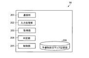
- FIG. 2 is a block diagram showing a configuration generated in accordance with a control program executed by a CPU (not shown) of the brake ECU 50.
- the brake ECU 50 implements a communication unit 201, an input processing unit 202, an acquisition unit 203, a determination unit 204, and a control unit 205 by executing a control program.
- a preliminary braking force map storage unit 206 is stored in a ROM (not shown) inside the brake ECU 50.
- the communication unit 201 transmits and receives information to and from the engine ECU 10 via the LAN 12. For example, the communication unit 201 receives information indicating the driving force output from the engine 11 from the engine ECU 10. Further, the communication unit 201 transmits a request for controlling the engine 11 to the engine ECU 10.
- the input processing unit 202 performs input processing on various information related to the vehicle 1.
- input information for example, a signal indicating the operation status of the CRAWL switch 23, a speed set by the target speed setting switch 24, wheel speeds of the wheel speed sensors 20FL, 20FR, 20RL, and 20RR, and acceleration by the acceleration sensor 25 are input. To process.
- the input processing unit 202 also calculates information necessary for the acquisition unit 203 and the determination unit 204 from the input processed information.
- the acquisition unit 203 When the vehicle 1 having wheels travels, the acquisition unit 203, based on the driving force of the vehicle 1 and the acceleration of the vehicle 1, the wheels FL, FR, RL, RR of the vehicle 1 and the wheels FL, The running resistance force generated between the road surface where FR, RL, and RR are grounded is acquired.
- the traveling resistance force of the present embodiment is a resistance force generated by friction between the wheels FL, FR, RL, RR of the vehicle 1 and the road surface.
- working resistance force is mentioned later, it does not restrict
- the determination unit 204 determines whether or not there is a step based on the running resistance and the amount of change (per time) in the running resistance.
- the step difference is determined in consideration of not only the magnitude of the running resistance but also the amount of change in the running resistance. That is, when the wheels FR, FL, RR, and RL of the vehicle 1 come into contact with the step on the road surface, the traveling resistance rapidly changes due to the step. Such a rapid change in driving resistance rarely occurs on a road surface such as a desert. For this reason, in this embodiment, the detection accuracy of the step can be improved by considering the amount of change in the running resistance in addition to the running resistance.
- the determination unit 204 of the present embodiment sets the traveling resistance acquired by the acquisition unit 203 at any time as a reference value, and then the difference between the traveling resistance acquired after the arbitrary time and the reference value Exceeds the difference threshold, and when the differential value (change amount per time) of the running resistance exceeds the differentiation threshold, it is determined that a step has occurred on the road surface.
- the control unit 205 controls the brake actuator 15 to apply a braking force to the vehicle 1.
- the control unit 205 of the present embodiment calculates a feedback braking force and / or a feedback driving force based on a deviation between the vehicle body speed and the target speed for each predetermined control cycle in order to bring the vehicle body speed close to the target speed. These braking forces and / or driving forces are applied to the wheels FR, FL, RR, RL.
- the control unit 205 starts control for applying a braking force to the vehicle 1 with respect to the brake actuator 15. At that time, preliminary braking control for operating the brake actuator 15 is performed. In other words, in a state where no braking force is applied, it takes time until the braking force is actually applied after the brake ECU 50 gives an instruction to apply the braking force to the wheels FR, FL, RR, RL. Cost. Therefore, in the present embodiment, in order to travel at the speed set by the crawl control, the control is for applying the braking force to the wheels of the vehicle 1 to the extent that the braking force is not substantially applied. Defines a braking force that does not cause trouble as a preliminary braking force.
- the control unit 205 starts to apply the preliminary braking force. After the preliminary braking force is applied in this way, the brake ECU 50 steeply applies a substantial braking force to the vehicle 1 so as not to give the driver a sense of jumping over the vehicle 1 after climbing the step. Can be granted.
- the control unit 205 of the present embodiment determines the preliminary braking force to be applied by operating the brake actuator 15 with reference to the preliminary braking force map storage unit 206.
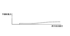
- FIG. 3 is a diagram illustrating a preliminary braking force map stored in the preliminary braking force map storage unit 206.
- the traveling resistance difference shown in the example shown in FIG. 3 is the difference between the current traveling resistance force and the reference value of the traveling resistance force.
- the preliminary braking force is determined based on the running resistance difference. As shown in FIG. 3, the preliminary braking force is set so as to increase as the running resistance difference increases (as the current running resistance increases as compared with the reference value).
- control unit 205 operates the brake actuator 15 so that the determined preliminary braking force (substantially no braking force is applied) is generated on the wheels FR, FL, RR, and RL.
- FIG. 4 is a diagram illustrating the timing of control performed while the vehicle 1 is traveling.
- crawl control has already been executed.
- Drawing 4 shows target speed TDV of crawl control.
- (1) in FIG. 4 shows the vehicle speed V0 of the vehicle 1.
- (5) in FIG. 4 shows the braking force B0 applied to the wheels FL, FR, RL, and RR of the vehicle 1.
- the driver depresses the brake pedal 13 from time t11 to time t13.
- the vehicle body speed V0 of the vehicle 1 decreases from the speed V11 to the speed '0' during the time t11 to t12.
- a braking reference speed TBVad serving as a reference for starting the application of the braking force is shown.
- the control unit 205 of the brake ECU 50 sets the braking reference speed TBVad. Control to gradually decrease to '0'.
- the control unit 205 performs control to increase the driving force so that the target speed TDV is reached according to the crawl control.
- the target driving force TDF in (2) of FIG. 4 is set as a driving force set as a target by the control unit 205.
- vehicles 1 start a run at time t15.
- the brake ECU 50 performs control to increase the braking reference speed TBVad.
- the control unit 205 applies the target control for applying the braking force.
- Control to increase the power TBF is performed.
- the target braking force TBF is a value set as a target by the brake ECU 50 to control the brake actuator 15 and apply braking force to the wheels FR, FL, RR, and RL.
- the brake actuator 15 applies the braking force B0 so as to follow the target braking force TBF. Then, after the time t16 has elapsed, the vehicle body speed V0 becomes lower than the braking reference speed TBVad, so that the control unit 205 performs control to decrease the target braking force TBF. As a result, the braking force B0 applied by the brake actuator 15 decreases.
- (2) in FIG. 4 shows driving force and the like.
- the gradient resistance force Fslope generated by the road gradient is shown.
- the gradient resistance force Fslope is positive, it is an uphill, and when it is negative, it is a downhill.
- (2) in FIG. 4 indicates the acceleration resistance force Fgx generated by the acceleration of the vehicle 1.
- the acceleration resistance force Fgx takes a negative value while the braking control of the vehicle 1 is performed between times t11 and t12. Further, after time t15, the acceleration resistance force Fgx increases steeply as the vehicle 1 starts to travel, but gradually decreases because the braking force B0 is applied as shown in FIG. 4 (5). I will do it.
- a running resistance force Freg generated between the wheels FR, FL, RR, and RL of the vehicle 1 and the road surface on which the wheels FR, FL, RR, and RL are grounded.
- the running resistance force Freg is equal to or greater than the value F11.
- the engine ECU 10 (the brake pedal 13 of the brake pedal 13) according to the instruction based on the crawl control transmitted from the communication unit 201 of the brake ECU 50. Control is performed to increase the target driving force TDF from time t13 when the depression is released.
- the target driving force TDF is a driving force set as a target by the engine ECU 10 to drive the engine 11.
- the driving force that is actually output from the engine 11 is also substantially equal to the target driving force TDF.
- the driving force is transmitted to the wheels FR, FL, RR, RL due to the increase of the target driving force TDF, and the running resistance force Freg also increases from time t14. Then, after the vehicle 1 starts to travel at time t15, the traveling resistance force Freg also decreases toward the value F11.
- the control unit 205 increases the target braking force TBF, and the communication unit 201 instructs the engine ECU 10, and the engine ECU 10 uses the conventional driving force Ffb (hereinafter referred to as a driving force Ffb based on feedback based on a speed deviation). , Also referred to as feedback driving force Ffb).
- the feedback driving force Ffb of the present embodiment is a driving adjusted from the previous feedback driving force Ffb based on the difference between the target speed and the actual speed, the difference between the target acceleration and the actual acceleration, and the like. Power.
- the determination unit 204 determines whether or not the road surface is a step, a difference between the traveling resistance and the reference value ((4) in FIG. 4), and a differential value of the traveling resistance (FIG. 4 (3)).
- the running resistance force (reference value 401) at time t14 is set as a reference value for calculating the difference in running resistance. Then, during the period from time t14 to time t16, the difference between the running resistance force Freg and the reference value 401 is calculated, and it is determined whether or not there is a step based on the difference.
- the running resistance force (reference value 402) at time t16 is set as a reference value for calculating the difference in running resistance.
- a difference between the running resistance force Freg and the reference value 402 is calculated, and it is determined whether or not there is a step based on the difference.
- the lowest running resistance force is set as a reference value within a predetermined period, but the reference value may be a value to be compared with the running resistance force, and the lowest running resistance is set. It is not limited to setting the force to the reference value.
- (3) in FIG. 4 shows the differential value DRF of the running resistance force.
- the determination unit 204 of the present embodiment determines whether or not the differential value DRF of the running resistance exceeds the threshold value KDR. In the example shown in (3), it can be confirmed that the differential value DRF of the running resistance exceeds the threshold value KDR within the period of time t14 to t15.
- FIG. 4 shows a difference (hereinafter also referred to as a running resistance difference) Fdiff between the running resistance force and the reference value.
- the determination unit 204 calculates the traveling resistance difference Fdiff by subtracting a set reference value (for example, the reference values 401 and 402) from the calculated traveling resistance force. Then, it is determined whether or not the running resistance difference Fdiff exceeds the threshold value Kdiff. In the example shown in (4), it can be confirmed that there is no period when the running resistance difference Fdiff exceeds the threshold value Kdiff.
- the determination unit 204 determines that there is a step when the differential value DRF exceeds the threshold value KDR and the running resistance difference Fdiff exceeds the threshold value Kdiff. In the example illustrated in FIG. 4, since there is no period in which the running resistance difference Fdiff exceeds the threshold value Kdiff, the determination unit 204 determines that there is no step, and the control unit 205 preliminarily brakes when the step occurs. Is not granted.
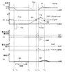
- FIG. 5 is a diagram illustrating the timing of control performed while the vehicle 1 is traveling.
- crawl control has already been executed.
- the crawl control target speed TDV, the vehicle body speed V0 of the vehicle 1, and the braking reference speed TBVad are set.
- the braking force B0 applied to the vehicle 1, the target braking force TBF, and the feedback braking force Bfb are set as in FIG.
- the feedback braking force Bfb is a braking force adjusted from the previous feedback braking force Bfb based on the difference between the target speed and the actual speed, the difference between the target acceleration and the actual acceleration, and the like.
- the braking force B0 does not increase during the period from time t21 to time t22 when the vehicle body speed V0 is decreasing. It can be confirmed that it is not based on the depression of the pedal 13.
- the control unit 205 of the brake ECU 50 performs control to decrease the braking reference speed TBVad.
- the gradient resistance force Fslope, the acceleration resistance force Fgx, the travel resistance force Freg, the target driving force TDF, and the feedback driving force Ffb are shown.
- the communication unit 201 of the brake ECU 50 causes the engine ECU 10 to have a speed set by crawl control.
- a request to increase the driving force is made.
- engine ECU10 raises target drive force TDF after time t22 vicinity.
- the traveling resistance force Freg also increases.
- (3) in FIG. 5 shows the differential value DRF of the running resistance force.
- the determination unit 204 of the present embodiment determines whether or not the differential value DRF of the running resistance exceeds the threshold value KDR. In the example shown in (3), it can be confirmed that the differential value DRF of the running resistance exceeds the threshold value KDR within the period of time t22 to t24.
- the determination unit 204 calculates the running resistance difference Fdiff by subtracting a set reference value (for example, the reference values 501, 502, and 503) from the calculated running resistance. Then, it is determined whether or not the running resistance difference Fdiff exceeds the threshold value Kdiff. In the example shown in (4), it can be confirmed that the running resistance difference Fdiff exceeds the threshold value Kdiff between time t23 and time t25.
- a set reference value for example, the reference values 501, 502, and 503
- the determination unit 204 of the present embodiment has a step difference between the time t23 and the time t24 because the running resistance differential value DRF exceeds the threshold KDR and the running resistance difference Fdiff exceeds the threshold Kdiff. judge. Then, as shown in (5) of FIG. 5, the control unit 205 performs control to apply the preliminary braking force based on the preliminary braking force map storage unit 206 between times t23 and t24.
- the vehicle body speed V0> the braking reference speed TBVad is satisfied at time t24. Since it is determined that there is a step by time t24, the control unit 205 of the present embodiment assumes that the step has been overcome when the vehicle body speed V0> the braking reference speed TBVad. A command to lower the torque of the engine 11 is given to the ECU 10, and the control unit 205 performs control to apply a braking force to the wheels FR, FL, RR, and RL.
- the control unit 205 applies braking force to the wheels FR, FL, RR, and RL with respect to the target braking force TBF when the vehicle body speed V0> the braking reference speed TBVad.
- the control unit 205 instructs the brake actuator 15 to apply the braking force at the maximum value.
- the braking force B0 increases with the target braking force TBF as a target. Therefore, in this embodiment, the braking response can be improved.
- the setting method of the target braking force TBF is not limited to the maximum value setting.
- the braking force TBF may be set so as to follow the feedback braking force Bfb.
- the engine ECU 10 performs adjustment to reduce the driving force from the feedback driving force Ffb by the difference between the feedback braking force Bfb and the actual braking force B0 in accordance with an instruction from the communication unit 201 of the brake ECU 50.
- the feedback amount is the greater of the adjustment amount based on the difference between the feedback braking force Bfb and the actual braking force B0, or the adjustment amount based on the difference between the vehicle body acceleration and the braking reference acceleration. Adjustment to lower the driving force from the driving force Ffb was performed.
- the detection accuracy of the road surface condition can be improved.
- 6 and 7 are flowcharts showing the above-described control procedure in the vehicle 1 of the present embodiment.
- the input processing unit 202 inputs various information related to the vehicle 1 from a sensor or the like (step S601).
- Examples of information to be input include wheel speeds for each wheel detected by the wheel speed sensors 20FL, 20FR, 20RL, and 20RR, acceleration detected by the acceleration sensor 25, torque force of the engine 11, and gear ratio of the main transmission 2a.
- the vehicle body acceleration is calculated based on the vehicle body speed calculated this time, the previously calculated vehicle body speed, and the calculation period of the vehicle body speed.
- the input processing unit 202 calculates a driving target speed and a driving target acceleration based on the speed set by the target speed setting switch 24 (step S604).
- the target speed is set so as to gradually change from the speed before setting to the speed after setting by applying a filter.
- the target acceleration is calculated based on the target speed calculated this time, the previously calculated target speed, and the target speed calculation cycle.
- step S605 when the input processing unit 202 determines that the vehicle body speed V0 is not 0, the previous feedback braking force is not 0, or the brake pressure by the brake pedal 13 is not 0 (step S605: No), the input processing unit 202 is The braking reference speed is calculated by a method different from that in step S606 (step S607).
- the maximum braking reference speed TBVmax is a speed corresponding to the crawl control target speed, and indicates a maximum speed set as a threshold (reference) for applying a braking force in order to maintain the target speed.
- the second predetermined value Kup is a constant set according to the embodiment.
- the input processing unit 202 calculates a braking reference acceleration from the braking reference speed (step S608).
- the braking reference acceleration is calculated based on the braking reference speed calculated this time, the previously calculated braking reference speed, and the calculation period of the braking reference speed.
- the input processing unit 202 calculates the gradient of the road surface on which the vehicle 1 is traveling and the gradient force (step S609).
- the input processing unit 202 of this embodiment calculates the gradient acceleration by subtracting the vehicle body acceleration calculated in step S603 from the acceleration detected by the acceleration sensor 25. Further, the input processing unit 202 calculates the gradient force by multiplying the acceleration of the gradient by the vehicle body load.
- the input processing unit 202 calculates the driving force, the braking force, and the actual acceleration force that are currently output from the vehicle 1 (step S610).
- the input processing unit 202 of the present embodiment includes the gear ratio of the main transmission 2a, the gear ratio of the sub-transmission 2b, the torque ratio of the transmission 2, the transmission efficiency of the transmission 2, and the torque of the engine 11. After multiplying by the final gear ratio, the driving force transmitted to the wheels FR, FL, RR, RL is calculated by dividing by the tire diameter.
- the input processing unit 202 of the present embodiment multiplies the wheel pressure, the cylinder area, the rotor effective diameter, and the brake factor, and then divides by the tire diameter, so that the wheels FR, FL, RR, The individual braking force of RL is calculated. And the input process part 202 calculates the braking force of a vehicle body by adding the braking force for every wheel for all four wheels. Further, the input processing unit 202 calculates the actual acceleration force by multiplying the acceleration of the vehicle body by the vehicle body load. Note that the parameters used for these calculations are the parameters input in step S601 and the parameters previously stored in the ROM (not shown).
- the acquisition unit 203 determines whether the vehicle body speed V0 is “0” (step S611). When it is determined that the vehicle body speed V0 is “0” (step S611: Yes), the acquisition unit 203 calculates a running resistance force generated between the wheels FR, FL, RR, RL and the road surface (step S612). .
- the acquisition unit 203 calculates a running resistance force generated between the wheels FR, FL, RR, RL and the road surface (step S612).
- the larger one of the value obtained by subtracting the actual acceleration force and the braking force from the currently output driving force and the previous traveling resistance force is set as the traveling resistance force (this time)
- Running resistance force MAX ((driving force ⁇ actual acceleration force ⁇ braking force), previous running resistance force)). Further, when the running resistance force is calculated, a filtering process may be performed to suppress the fluctuation range.
- the acquisition unit 203 performs a setting process for the reference value of the running resistance (step S614).
- a specific method for setting the reference value will be described later.
- the acquisition part 203 calculates the differential value of driving resistance (step S615).
- the differential value of the traveling resistance is calculated based on the currently calculated traveling resistance, the previously calculated traveling resistance, and the calculation cycle of the traveling resistance.
- the acquisition unit 203 calculates a running resistance difference that is a difference between the running resistance force and the reference value (step S616).
- the determination unit 204 determines whether or not (differential value of running resistance> differential threshold KDR) and (running resistance difference> difference threshold Kdiff) are satisfied (step S617).
- the differential value of the running resistance> the threshold value KDR for differentiation it is possible to prevent the situation where the road surface is gradually changed to a road surface having a high running resistance such as a desert from being erroneously determined as a step.
- the traveling resistance difference> the difference threshold Kdiff it is possible to prevent erroneous determination as a step when the vehicle starts on a road surface having a high traveling resistance such as a desert.
- an appropriate value is set as the differentiation threshold KDR or the difference threshold Kdiff according to the embodiment.
- step S617 when the determination unit 204 determines that both (differential value of running resistance> differential threshold KDR) and (running resistance difference> difference threshold Kdiff) are satisfied (step S617: Yes), the control unit 205 Based on the preliminary braking force map storage unit 206, the preliminary braking force corresponding to the running resistance difference is calculated (step S619).
- control unit 205 determines whether or not both the previous vehicle body speed ⁇ the braking reference speed TBVad and the current vehicle body speed> the braking reference speed TBVad are satisfied (step S620). For example, when the vehicle 1 starts traveling between the previous time and the current time, the previous vehicle speed ⁇ the braking reference speed TBVad and the current vehicle speed> the braking reference speed TBVad are both satisfied.
- step S620 determines that at least one of the previous vehicle speed ⁇ the braking reference speed TBVad or the current vehicle speed> the braking reference speed TBVad is not satisfied (step S620: No).
- step S620 determines that at least one of the previous vehicle speed ⁇ the braking reference speed TBVad or the current vehicle speed> the braking reference speed TBVad is not satisfied (step S620: No)
- the process proceeds to step S623. .
- step S620 Yes
- the control unit 205 determines that both the previous vehicle body speed ⁇ the braking reference speed TBVad and the current vehicle body speed> the braking reference speed TBVad are satisfied (step S620: Yes)
- the running resistance difference and the previous feedback are determined.
- the larger one of the braking forces is set as the feedback braking force (step S621).
- the first flag is a flag for setting the braking force
- the second flag is a flag for setting the driving force of the engine 11.
- the preliminary braking force is used as the braking force.
- a settable maximum value is set (step S624), and the process proceeds to step S628.
- step S625 Yes
- the smaller one of the previous feedback braking force and the vehicle body braking force MIN (previous feedback braking force) , Vehicle system power)
- MIN previously feedback braking force
- Vehicle system power Vehicle system power
- the control unit 205 determines that the second flag is not ON (step S628: No)
- the first adjustment driving force is set to 0 (step S630), and the process proceeds to step S633.
- the first adjustment driving force MAX (MIN ((driving force ⁇ gradient force), (vehicle acceleration ⁇ braking) Reference acceleration) ⁇ vehicle load)
- the previous first adjustment driving force ⁇ the third predetermined value Kdw2, 0) are set (step S629).
- the adjustment driving force is a parameter used when adjusting the feedback driving force to calculate the target driving force.
- the third predetermined value Kdw2 is a constant set in accordance with the embodiment.
- the control unit 205 calculates a feedback braking force (step S633).
- the control unit 205 controls the MAX (the (provisional) feedback braking force calculated in step S626 or the previous feedback braking force (if not calculated in step S626) + (vehicle speed ⁇ braking).
- the feedback braking force is calculated from (reference speed) ⁇ fourth predetermined value + (vehicle body acceleration ⁇ braking reference acceleration) ⁇ fifth predetermined value), 0).
- the feedback braking force is a value obtained by adjusting the (temporary) feedback control force or the previous feedback control force based on the vehicle body speed and the vehicle body acceleration.
- the fourth predetermined value and the fifth predetermined value are constants set according to the embodiment.
- the feedback braking force is calculated based on the vehicle body speed and the vehicle body acceleration.
- the present invention is not limited to using both, and either the vehicle body speed or the vehicle body acceleration may be used. .
- control unit 205 calculates a target braking force from MAX (feedback braking force, preliminary braking force) (step S634).
- MAX feedback braking force, preliminary braking force
- control unit 205 calculates a feedback driving force (step S635).
- the control unit 205 sets MAX (previous feedback driving force + (vehicle body speed ⁇ braking reference speed) ⁇ sixth predetermined value + (vehicle body acceleration ⁇ braking reference acceleration) ⁇ seventh predetermined value), 0 ) To calculate the feedback driving force.
- the sixth predetermined value and the seventh predetermined value are constants set according to the embodiment.
- the feedback driving force is a value adjusted to the previous feedback driving force based on the vehicle body speed and the vehicle body acceleration.
- the control unit 205 calculates a target driving force from the feedback driving force-MAX (first adjustment driving force, second adjustment driving force) (step S637).
- the feedback driving force is calculated in the process of step S635.
- the feedback drive force is adjusted based on the first adjustment drive force or the second adjustment drive force.
- the first adjustment driving force is calculated so as not to give the driver a feeling of jumping based on the difference between the vehicle body acceleration and the braking reference acceleration when it is determined that the step has been overcome (in step S620).
- the adjustment value of the driving force is an adjustment value based on the feedback braking force calculated based on the speed and acceleration of the vehicle and the braking force actually output. This is an adjustment value for lowering the torque.
- step S637 the larger one of the first adjustment driving force and the second adjustment driving force is subtracted from the feedback driving force to calculate the target driving force.
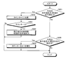
- FIG. 8 is a flowchart showing a procedure of the above-described processing in the vehicle 1 of the present embodiment.
- the initial value of the counter is 0.
- the acquisition unit 203 determines whether or not the current running resistance is greater than the previous running resistance (step S801). If it is determined that the current running resistance> the previous running resistance is satisfied (step S801: Yes), “1” is added to the counter (step S802).
- step S803: Yes the previous traveling resistance is set as the reference value of the traveling resistance (step S804), and the process ends.
- step S801 if it is determined that the current running resistance> previous running resistance is not satisfied (step S801: No), it is determined whether the current running resistance ⁇ previous running resistance is satisfied. (Step S805). If it is determined that the current running resistance ⁇ the previous running resistance is not satisfied (step S805: No), the process is terminated.
- step S805 if it is determined that the current running resistance ⁇ the previous running resistance is satisfied (step S805: Yes), the acquisition unit 203 initializes the counter with “0” (step S806), and ends the process.
- the reference value of the running resistance force is set according to the process shown in FIG.
- the acquisition unit 203 sets the travel resistance acquired before the increase as the reference value at the timing when the travel resistance increases from the state where the travel resistance decreases or does not change.
- the minimum value of the traveling resistance force in an arbitrary time zone is set as the reference value. This facilitates comparison with the subsequent running resistance.
- the minimum value of the traveling resistance force in an arbitrary time zone is set as the reference value by the above-described processing procedure will be described.
- the reference value is not limited to the minimum value, and traveling Any value can be used as a reference when comparing the resistance.
- the road surface level difference is determined based on the running resistance and the amount of change in the running resistance. Therefore, even if it is road surface conditions, such as a desert, the detection accuracy of a level
- the brake ECU 50 of the present embodiment by applying a preliminary braking force when it is determined that the step is a step, the braking force can be applied immediately after overcoming the step, so that Thus, it is possible to prevent the vehicle 1 from giving a feeling of popping out. Thereby, a comfortable ride feeling can be provided to the driver. Moreover, since the acceleration after the vehicle 1 gets over a level
Landscapes
- Engineering & Computer Science (AREA)
- Transportation (AREA)
- Mechanical Engineering (AREA)
- Chemical & Material Sciences (AREA)
- Combustion & Propulsion (AREA)
- Automation & Control Theory (AREA)
- Physics & Mathematics (AREA)
- Mathematical Physics (AREA)
- Regulating Braking Force (AREA)
- Control Of Driving Devices And Active Controlling Of Vehicle (AREA)
Abstract
車両制動装置は、例えば、車輪を有する車両が走行する際に、当該車両の駆動力と当該車両の加速度とに基づいて、当該車両の車輪と当該車輪が接地する路面との間で生じる走行抵抗力を取得する取得部と、走行抵抗力と予め定められた値との差分が第1の閾値を超えるとともに、当該走行抵抗力の微分値が第2の閾値を超えた場合に、当該車両の車輪に制動力を付与するための制御を開始する制御部と、を備える。
Description
本発明の実施形態は、車両制動装置に関する。
車両がオフロード走行時の安全性、利便性を向上させるための技術が提案されている。例えば、このような技術として、クロールコントロール(Crawl Control)技術がある。クロールコントロールは、岩石路、雪道、急勾配の坂道などの微妙な速度調整を必要とする路面で、ドライバーの運転操作をサポートするための技術である。
クロールコントロールにおいては、運転者により設定された低速度(例えば1~5km/h)で走行するために、エンジンとブレーキを最適に制御することにより、車輪の空転を出来る限り小さくすることを可能としている。
ところで、オフロード走行では、障害物等によって生じた段差を乗り越えるために、高い駆動力が必要となる。しかしながら、高い駆動力を出力して段差を乗り越えた後、車両が必要以上に加速してしまい、飛び出し感を与える状況が生じていた。このために、段差の乗り上げ後における制動応答性を向上させるために、段差の乗り上げと判定された場合には、実質的に制動力が付与されない程度に制動手段を作動(予備制動力を付与)させる技術がある。
しかしながら、従来技術においては、トルクに応じた速度が検出されない場合に、段差と判断しているが、トルクの変化量に応じた速度が検出されない状況は、段差以外に、砂漠等の走行抵抗力が高い路面などを走行している場合など他の状況も考えられる。このように、段差以外で予備制動力が付与されると、燃費の低下が生じうる。さらには、特許文献1は、低速における自動速度制御(クロールコントロール)に関する技術でもない。
本発明は、上記に鑑みてなされたものであって、路面に応じた車両の速度制御を実現する車両制動装置を提案する。
実施形態の車両制動装置は、例えば、車輪を有する車両が走行する際に、当該車両の駆動力と当該車両の加速度とに基づいて、当該車両の車輪と当該車輪が接地する路面との間で生じる走行抵抗力を取得する取得部と、走行抵抗力と予め定められた値との差分が第1の閾値を超えるとともに、当該走行抵抗力の微分値が第2の閾値を超えた場合に、当該車両の車輪に制動力を付与するための制御を開始する制御部と、を備える。
また、上述した車両制御装置では、例えば、前記取得部は、さらに、前記車両の速度を取得し、前記制御部は、さらに、前記車輪に制動力を付与するための制御を開始した後、前記車両の速度が第1の速度を超えた場合に、前記車輪に制動力を付与する。
また、上述した車両制動装置では、例えば、前記制御部は、さらに、前記車輪に制動力を付与するための制御を開始した後、前記車両の速度が第1の速度を超えた場合に、前記車輪に制動力を付与するアクチュエータに対して、前記車輪に設定可能な最大値で制動力を付与するように指示する。
また、上述した車両制動装置では、例えば、前記制御部は、さらに、前記車両の速度が前記第1の速度を超えた場合に、前記車両の速度及び加速度に応じて算出された制動力と実際に出力された制動力との差分に基づいた調整量、及び前記車両の加速度に基づいた調整量のうちいずれか大きい値を、前記車両の駆動力から低減させる。
また、上述した車両制動装置では、例えば、前記制御部は、さらに、任意の時間帯で前記取得部により取得された走行抵抗力の最低値を、前記基準値として設定する。
また、上述した車両制動装置では、例えば、前記制御部は、さらに、当該車両が停止し、運転者が前記車両の制動制御を行っていない場合に、制動力を付与する基準となる前記第1の速度を減少させる制御を行う。
以下に示す実施形態では、車両制動装置をブレーキECUに適用した例について説明するが、以下に示す実施形態は、車両制動装置の適用先をブレーキECUに制限するものではなく、車輪に制動力を付与するための装置であれば良い。
図1は、本実施形態の車両の全体的な構成を示したブロック図である。図1に示されるように、本実施形態は、車両1が、複数(本実施形態では4つ)ある車輪(左前輪FL、右前輪FR、左後輪RL、及び右後輪RR)の全てが駆動輪として機能する、いわゆる四輪駆動車である例について説明するが、四輪駆動車に制限するものではなく、様々な車両に適用可能とする。
本実施形態の車両1には、エンジンECU10からの制御に従って駆動力を発生するエンジン11が設けられている。さらに、車両1には、エンジン11の出力軸に接続された主変速機2aと、トルクの伝達経路上において主変速機2aよりも下流側(即ち、車輪側)に配置される副変速機2bとが設けられている。副変速機2bのレンジ(変速段)は、運転者による(図示しないアクセルペダル等)操作や、エンジンECU10からの制御に従って、車輪FR,FL,RR,RL側へのトルクの伝達比率が異なる変速段への切替えを可能とする。なお、本実施形態では、変速機2の構成を、主変速機2a及び副変速機2bを組み合わせたものとするが、どのような構成でも良い。
また、上記伝達経路上において副変速機2bよりも下流側には、センタディファレンシャル18が設けられており、エンジン11で発生したトルクは、センタディファレンシャル18を介して前輪FR,FL側及び後輪RR,RL側に駆動力としてそれぞれ伝達される。また、センタディファレンシャル18よりも前輪FR,FL側には、フロントディファレンシャル6が設けられている。そして、フロントディファレンシャル6は、前輪側のシャフト4を介してセンタディファレンシャル18から伝達された駆動力を、前輪FR,FLにそれぞれ伝達する。
また、センタディファレンシャル18よりも後輪RR,RL側には、リアディファレンシャル8が設けられている。そして、リアディファレンシャル8は、後輪側のシャフト5を介してセンタディファレンシャル18から伝達された駆動力を、後輪RL,RRにそれぞれ伝達する。このようにエンジン11で発生したトルクが各車輪FR,FL,RR,RLに伝達されることで、各車輪FR,FL,RR,RLがそれぞれ回転して車両1が走行する。
エンジンECU10は、図示しないCPU、ROM及びRAMなどを有する。エンジンECU10は、運転者によるアクセルの操作量を、図示しないアクセル操作量センサから受信する。そして、エンジンECU10は、アクセル操作量などに基づいて、エンジン11を制御する。
車両1には、運転者によるブレーキペダル13の操作状況に応じたブレーキ液圧を発生するマスタシリンダ(M/Cとも称す)14と、当該M/C14で生じているブレーキ圧を検出するM/C圧センサ22と、が設けられている。
ブレーキアクチュエータ15は、ブレーキ圧に応じた制動力を、各車輪FR,FL,RR,RLに付与する。具体的には、ブレーキアクチュエータ15は、ブレーキ圧に応じて、車輪FR,FL,RR,RL毎に設けられたホイールシリンダ(W/Cとも称す)16FL、16FR、16RL、16RRにブレーキ液を供給する制御を行う。これにより生じるブレーキパッドとディスクとの間の摩擦により、各車輪FR,FL,RR,RLに制動力が付与される。また、ブレーキアクチュエータ15は、各車輪FR,FL,RR,RLに対する制動力を個別に調整可能とする。
ブレーキアクチュエータ15は、運転者がブレーキペダル13を操作するか否かにかかわらず、ブレーキECU50からの制御に従って、各車輪FR,FL,RR,RLに対して制動力を付与できる。
次に、ブレーキアクチュエータ15を制御可能なブレーキECU50について説明する。ブレーキECU50には、ブレーキスイッチ21に加え、各車輪FR,FL,RR,RLの車輪速度を検出するための車輪速度センサ20FL、20FR、20RL、20RRが電気的に接続されている。また、ブレーキECU50には、運転者によるブレーキペダル13の操作量を検出するためのM/C圧センサ22とも電気的に接続されている。また、ブレーキECU50には、車両1の前後方向における加速度、車両1の左右方向における加速度、及び車両1のヨー方向の加速度を検出するための加速度センサ25が電気的に接続されている。
加速度センサ25が検出する前後方向の加速度は、車両1の走行する路面が水平である場合、前後方向に車両1が加速する場合に正の値となり、前後方向に車両1が減速する場合に負の値となる。
ブレーキECU50は、CPU、ROM及びRAMなどで構成されるデジタルコンピュータを有している。ROMには、CPUに実行される制御プログラム及び各種マップなどが記憶されている。また、RAMには、適宜書き換えられる各種情報(車体速度など)が記憶される。
さらに、本実施形態のブレーキECU50は、CRAWLスイッチ23と、目標速度設定スイッチ24と、ブレーキスイッチ21と、が電気的に接続されている。そして、ブレーキECU50は、CRAWLスイッチ23、及び目標速度設定スイッチ24から送信される信号に従って、ブレーキアクチュエータ15を制御する。
例えば、ブレーキECU50は、CRAWLスイッチ23で行われた操作に従って、クロールコントロールなどの速度制限制御を行う。この際に、ブレーキECU50は、車両1の車体速度が、目標速度設定スイッチ24で設定された速度になるように速度制限制御を行う。例えば、ブレーキECU50は、車両1の車体速度から目標速度設定スイッチ24で設定された速度と比べて実際の速度が大きいほど、目標とする制動力に大きな値を設定する。そして、ブレーキECU50は、目標とする制動力に応じた制動力が各車輪FR、FL、RR、RLに付与されるようにブレーキアクチュエータ15を制御する。
本実施形態では、エンジンECU10とブレーキECU50との間をLAN12で接続している。これにより、エンジンECU10と、ブレーキECU50と、の間で情報の送受信を可能とする。例えば、クロールコントロールに従って車両1の速度制御する際、エンジンECU10による駆動力制御と、ブレーキECU50による制動力制御と、の連携が可能となる。
例えば、クロールコントロールで、運転者に設定された低速度で走行する際に、エンジンECU10とブレーキECU50との間で速度、駆動力、及び制動力に関する情報を送受信することで、微妙な速度調整を実現できる。
ところで、従来のように、トルクに対応する速度が出力されない場合は、段差がないにもかかわらず、段差がある場合と同様の制動制御が行われていたが、燃費等を考慮すると好ましくない。そこで、本実施形態は、路面の状況に応じた制動制御を実現する。本実施形態では、走行抵抗力に応じて、路面の状況を認識し、当該状況に従って制動制御を行うこととした。
図2は、ブレーキECU50の(図示しない)CPUで実行される制御プログラムに従って生成される構成を示したブロック図である。図2に示されるように、ブレーキECU50は、制御プログラムを実行することで、通信部201と、入力処理部202と、取得部203と、判定部204と、制御部205と、を実現する。また、ブレーキECU50の内部の(図示しない)ROMに、予備制動力マップ記憶部206が格納されている。
通信部201は、LAN12を介して、エンジンECU10との間で情報の送受信を行う。例えば、通信部201は、エンジンECU10から、エンジン11が出力している駆動力を示す情報を受信する。さらに、通信部201は、エンジン11を制御するための要求を、エンジンECU10に対して送信する。
入力処理部202は、車両1に関する様々な情報を入力処理する。入力する情報としては、例えば、CRAWLスイッチ23の操作状況を示す信号、目標速度設定スイッチ24で設定された速度、車輪速度センサ20FL、20FR、20RL、20RRの車輪速度、加速度センサ25による加速度を入力処理する。
さらに、入力処理部202は、入力処理された情報から、取得部203や判定部204で必要な情報の算出等も行う。
取得部203は、車輪を有する車両1が走行する際に、当該車両1の駆動力と当該車両1の加速度とに基づいて、当該車両1の車輪FL、FR、RL、RRと当該車輪FL、FR、RL、RRが接地する路面との間で生じる走行抵抗力を取得する。本実施形態の走行抵抗力は、車両1の車輪FL、FR、RL、RRと路面との間の摩擦で生じる抵抗力とする。なお、走行抵抗力の算出手法は後述するが、後述する手法に制限するものではなく、どのような手法を用いても良い。
判定部204が、走行抵抗力と、走行抵抗力の(時間あたりの)変化量と、に基づいて、段差であるか否かを判定する。本実施形態では、走行抵抗力の大きさのみならず、走行抵抗力の変化量を考慮して、段差判定を行うこととした。つまり、車両1の車輪FR、FL、RR、RLが、路面の段差と接触した場合、当該段差により走行抵抗力が急激に変化する。このような急激な走行抵抗力の変化は、砂漠などの路面では生じることは少ない。このため、本実施形態では、走行抵抗力に加えて、走行抵抗の変化量を考慮することで、段差の検出精度を向上させることができる。
本実施形態の判定部204は、任意の時に取得部203により取得された走行抵抗力を基準値として設定した上で、当該任意の時以降に取得された走行抵抗力と当該基準値との差分が当該差分用の閾値を超えるとともに、当該走行抵抗力の微分値(時間あたりの変化量)が当該微分用の閾値を超えた場合に、路面に段差が生じたと判定する。
制御部205は、ブレーキアクチュエータ15に対して、車両1に制動力を付与するための制御を行う。本実施形態の制御部205は、車体速度を目標速度に近づけるために、所定の制御周期毎に車体速度と目標速度との偏差に基づいて、フィードバック制動力、及び/又はフィードバック駆動力を演算し、これらの制動力、及び/又は駆動力を、車輪FR、FL、RR、RLに付与する。
例えば、判定部204により、路面に段差が生じたと判定された場合に、制御部205が、ブレーキアクチュエータ15に対して、当該車両1に制動力を付与するための制御を開始する。その際に、ブレーキアクチュエータ15を作動させる、予備制動制御を行う。つまり、制動力をまったく付与していない状態だと、ブレーキECU50が車輪FR、FL、RR、RLに対して制動力を付与する指示を出してから、実際に制動力が付与されるまで時間を要する。そこで、本実施形態では、実質的に制動力が付与されない程度、換言すれば、車両1の車輪に制動力を付与するための制御であって、クロールコントロールで設定された速度で走行するためには支障が生じない程度の制動力を予備制動力と定義する。そして、判定部204により、段差が生じたと判断された場合に、制御部205が、予備制動力の付与を開始する。このように予備制動力を付与された後であれば、段差を乗りあげた後、運転者に車両1の飛び越し感を与えないように、ブレーキECU50が、車両1に実質的な制動力を急峻に付与することが可能となる。
本実施形態の制御部205は、ブレーキアクチュエータ15を作動させて付与する予備制動力を、予備制動力マップ記憶部206を参照して決定する。図3は、予備制動力マップ記憶部206に記憶されている予備制動力マップを例示した図である。図3に示される例に示された走行抵抗差分は、現在の走行抵抗力と走行抵抗力の基準値との差分とする。そして、当該走行抵抗差分に基づいて、予備制動力を決定する。図3に示されるように、走行抵抗差分が大きくなるほど(現在の走行抵抗力が基準値と比べて大きくなるほど)、予備制動力が大きくなるように設定される。
そして、制御部205は、車輪FR、FL、RR、RLに、決定された(実質的に制動力が付与されない程度の)予備制動力が生じるように、ブレーキアクチュエータ15を作動させる。
次に、車両1が走行中に行われる制御について説明する。図4は、車両1が走行中に行われる制御のタイミングを例示した図である。図4に示される例では、既にクロールコントロールが実行されているものとする。そして、図4の(1)に、クロールコントロールの目標速度TDVが示されている。
図4の(1)では、車両1の車体速度V0として示している。一方、図4の(5)では、車両1の車輪FL、FR、RL、RRに掛けられた制動力B0を示している。(5)の制動力B0に示されるように、時刻t11~t13の間、運転者によるブレーキペダル13の踏み込みが行われている。これにより、(1)で示されるように、時刻t11~t12の間に、車両1の車体速度V0が、速度V11から速度‘0’まで減少している。
なお、図4の(1)では、クロールコントロールにおいて、制動力の付与を開始する基準となる制動基準速度TBVadを示している。車体速度V0がクロールコントロールの目標速度TDVに従っている場合、ブレーキECU50は、制動基準速度TBVadを、目標速度TDVより少し速い速度に設定する(例えば、目標速度TDVがV11の場合、制動基準速度TBVad=V12(V12>V11)と設定する)。そして、車体速度V0=0になった(車両1が停止していると判定された)後、ブレーキペダル13の踏み込みが解除された際に、ブレーキECU50の制御部205は、制動基準速度TBVadを‘0’まで徐々に減少させる制御を行う。
図4の(1)に示す例では、運転者は、時刻t13にブレーキペダル13の踏み込みが解除された後、制御部205は、クロールコントロールに従って目標速度TDVになるように駆動力が増加させる制御を行う(図4の(2)の目標駆動力TDFが、制御部205により目標として設定された駆動力とする)。これにより、図4の(1)に示されるように、時刻t15で車両1が走行を開始する。車両1の走行が開始され、車体速度V0が増加開始した時、ブレーキECU50は、制動基準速度TBVadを増加させる制御を行う。
なお、時刻t15~t16までの間は、車体速度V0が、制動基準速度TBVadより高いため、図4の(5)に示されるように、制御部205が、制動力を付与するための目標制動力TBFを増加させる制御を行う。なお、目標制動力TBFは、ブレーキECU50が、ブレーキアクチュエータ15を制御して、車輪FR、FL、RR、RLに制動力を付与するために目標として設定した値とする。
これにより、ブレーキアクチュエータ15は、目標制動力TBFに追従するように、制動力B0を付与する。そして、時刻t16経過後、車体速度V0が、制動基準速度TBVadより低くなるため、制御部205が、目標制動力TBFを減少させる制御を行う。これにより、ブレーキアクチュエータ15が付与する制動力B0が減少する。
図4の(2)は、駆動力等を示している。(2)では、路面の勾配で生じる勾配抵抗力Fslopeで示している。勾配抵抗力Fslopeが、正の場合に上り坂であり、負の場合に下り坂となる。
また、図4の(2)は、車両1の加速度で生じる加速抵抗力Fgxで示している。加速抵抗力Fgxは、時刻t11~t12の間の車両1の制動制御が行われている間に、負の値となる。さらに、加速抵抗力Fgxは、時刻t15以降、車両1の走行が開始するために急峻に増加するが、図4の(5)に示されるように制動力B0が付与されるため、徐々に低下していく。
また、車両1の車輪FR、FL、RR、RLと、当該車輪FR、FL、RR、RLが接地する路面と、の間で生じる走行抵抗力Fregとして示している。図4の(2)で示す例では、路面が砂漠等であるため、走行抵抗力Fregは値F11以上となる。
そして、図4の(2)に示されるように、時刻t13でブレーキペダルを離した後、ブレーキECU50の通信部201から送信されるクロールコントロールに基づく指示に従って、エンジンECU10は、(ブレーキペダル13の踏み込みが解除された)時刻t13から目標駆動力TDFを増加させる制御を行う。なお、目標駆動力TDFは、エンジンECU10が、エンジン11を駆動させるために目標として設定した駆動力とする。そして、実際にエンジン11で出力する駆動力も、当該目標駆動力TDFとほぼ一致するものとする。
目標駆動力TDFの増加により駆動力が車輪FR、FL、RR、RLに伝達され、時刻t14から走行抵抗力Fregも増加していく。そして、時刻t15の車両1の走行開始した後、走行抵抗力Fregも、値F11に向けて減少していく。
なお、本実施形態では、時刻t15以降、(1)に示されるように車体速度V0が、制動力を付与する基準となる制動基準速度TBVadを上回っている。このため、制御部205は、目標制動力TBFを上昇させると共に、通信部201が、エンジンECU10に指示し、エンジンECU10が、目標駆動力TDFを、従来の速度偏差によるフィードバックによる駆動力Ffb(以後、フィードバック駆動力Ffbとも称す)より小さくなるよう制御する。本実施形態のフィードバック駆動力Ffbは、前回のフィードバック駆動力Ffbから、目標とする速度と実際の速度との差、及び目標とする加速度と実際の加速度との差等に基づいて調整された駆動力とする。
本実施形態のブレーキECU50において、判定部204は路面が段差であるか否かの判定を、走行抵抗力と基準値との差分(図4の(4))、及び走行抵抗の微分値(図4の(3))に基づいて行う。図4に示す例では、走行抵抗の差分を算出するための基準値として、時刻t14の走行抵抗力(基準値401)を設定する。そして時刻t14~t16までの間は、走行抵抗力Fregと、基準値401との差分を算出し、当該差分に基づいて、段差か否かの判定を行う。
その後、走行抵抗の差分を算出するための基準値として、時刻t16の走行抵抗力(基準値402)を設定する。そして時刻t16以降は、走行抵抗力Fregと、基準値402との差分を算出し、当該差分に基づいて、段差か否かの判定を行う。なお、本実施形態は、予め定められた期間内のうち、最も低い走行抵抗力を基準値として設定するが、基準値は走行抵抗力の比較対象となる値であればよく、最も低い走行抵抗力を基準値に設定することに制限するものではない。
図4の(3)は、走行抵抗力の微分値DRFを示している。本実施形態の判定部204は、走行抵抗力の微分値DRFが、閾値KDRを超えるか否かを判定する。(3)に示される例では、時刻t14~t15の期間内で、走行抵抗力の微分値DRFが、閾値KDRを超えていることを確認できる。
図4の(4)は、走行抵抗力と基準値との差分(以下、走行抵抗差分とも称す)Fdiffを示している。本実施形態では、判定部204が、算出された走行抵抗力から、設定された基準値(例えば基準値401、402)を減算することで、走行抵抗差分Fdiffを算出する。そして、走行抵抗差分Fdiffが、閾値Kdiffを超えているか否かを判定する。(4)に示される例では、走行抵抗差分Fdiffが、閾値Kdiffを超えた期間がないことを確認できる。
本実施形態では、判定部204は、微分値DRFが閾値KDRを超えた上で、走行抵抗差分Fdiffが閾値Kdiffを超えた場合に、段差があると判断する。図4に示す例では、走行抵抗差分Fdiffが、閾値Kdiffを超えた期間がないため、判定部204は、段差がないと判定し、制御部205は、段差が生じたことに伴う予備制動力の付与を行わない。
図5は、車両1が走行中に行われる制御のタイミングを例示した図である。図5に示される例では、既にクロールコントロールが実行されているものとする。そして、図5の(1)では、図4と同様に、クロールコントロールの目標速度TDV、車両1の車体速度V0、及び制動基準速度TBVadとする。
図5の(1)に示されるように、時刻t21で車体速度V0が減少し始め、時刻t22で車体速度V0=‘0’となる。
なお、図5の(5)では、図4と同様に、車両1に掛けられた制動力B0、目標制動力TBF、及びフィードバック制動力Bfbとする。フィードバック制動力Bfbは、前回のフィードバック制動力Bfbから、目標とする速度と実際の速度との差、及び目標とする加速度と実際の加速度との差等に基づいて調整された制動力とする。
図5の(5)に示されるように、車体速度V0が減少している時刻t21~時刻t22の期間内では、制動力B0は上昇していないため、車体1の停止が、運転者のブレーキペダル13の踏み込みに基づいたものでないことが確認できる。
そして、図5の(1)に示されるように、車体速度V0が減少し、車両1が停止していると判定され、且つ運転者がブレーキペダル13を踏み込んでいないと判定される場合に、ブレーキECU50の制御部205は、制動基準速度TBVadを減少させる制御を行う。
図5の(2)では、図4と同様に、勾配抵抗力Fslope、加速抵抗力Fgx、走行抵抗力Freg、目標駆動力TDF、フィードバック駆動力Ffbとして示している。図5の(2)に示されるように、車体速度V0が“0”になる時刻t22近傍で、ブレーキECU50の通信部201は、エンジンECU10に対して、クロールコントロールで設定された速度になるように、駆動力を上昇させる要求を行う。これにより、時刻t22近傍以降、エンジンECU10が、目標駆動力TDFを上昇させる。この目標駆動力TDFの上昇に従って、走行抵抗力Fregも上昇する。
図5の(3)は、走行抵抗力の微分値DRFを示している。本実施形態の判定部204は、走行抵抗力の微分値DRFが、閾値KDRを超えるか否かを判定する。(3)に示される例では、時刻t22~t24の期間内で、走行抵抗力の微分値DRFが、閾値KDRを超えていることを確認できる。
図5の(4)は、走行抵抗力と基準値との間の走行抵抗差分Fdiffを示している。本実施形態では、判定部204が、算出された走行抵抗力から、設定された基準値(例えば基準値501、502、503)を減算することで、走行抵抗差分Fdiffを算出する。そして、走行抵抗差分Fdiffが、閾値Kdiffを超えているか否かを判定する。(4)に示される例では、時刻t23~時刻t25の間、走行抵抗差分Fdiffが、閾値Kdiffを超えていることを確認できる。
そこで、本実施形態の判定部204は、時刻t23~時刻t24の間、走行抵抗力の微分値DRFが閾値KDRを超えると共に、走行抵抗差分Fdiffが閾値Kdiffを超えているため、段差があると判定する。そして、図5の(5)に示されるように、制御部205は、時刻t23~t24の間に、予備制動力マップ記憶部206に基づいて、予備制動力を付与する制御を行う。
図5の(1)に示す例では、時刻t24に車体速度V0>制動基準速度TBVadとなる。時刻t24までに段差があると判定しているため、本実施形態の制御部205は、車体速度V0>制動基準速度TBVadとなった時点で、段差を乗り越えたものとして、通信部201が、エンジンECU10に対してエンジン11のトルクを下げる命令を行うと共に、制御部205が、車輪FR、FL、RR、RLに制動力を付与する制御を行う。
図5の(5)に示されるように、制御部205は、車体速度V0>制動基準速度TBVadとなった時点で、目標制動力TBFに対して、車輪FR、FL、RR、RLに制動力として設定可能な最大値を設定する。これにより、制御部205は、ブレーキアクチュエータ15に対して、当該最大値で制動力を付与するように指示することになる。これにより、制動力B0は、目標制動力TBFを目標に上昇していく。従って、本実施形態では、制動応答性を向上させることができる。なお、本実施形態では、目標制動力TBFの設定手法を最大値の設定に制限するものではなく、例えば、フィードバック制動力Bfbに追従するように制動力TBFを設定しても良い。
しかしながら、フィードバック制動力Bfbと、実際の制動力B0との差が大きいと、車両1の走行で、運転者に飛び出し感を与える可能性がある。そこで、本実施形態のエンジンECU10は、ブレーキECU50の通信部201からの指示に従って、フィードバック制動力Bfbと実際の制動力B0との差分だけ、フィードバック駆動力Ffbから駆動力を下げる調整を行う。
図5に示す例では、時刻t24~t25の期間で、フィードバック制動力Bfbと実際の制動力B0との差分だけ、フィードバック駆動力Ffbから駆動力を下げる調整を行ったが、このような調整手法に制限するものではなく、車体加速度と制動基準加速度との違いに基づいて駆動力を下げる調整を行っても良い。
本実施形態では、フィードバック制動力Bfbと実際の制動力B0との差分に基づいた調整量と、車体加速度と制動基準加速度との違いに基づいた調整量と、のうちいずれか大きい方で、フィードバック駆動力Ffbから駆動力を下げる調整を行うこととした。
図5に示す例では、“フィードバック制動力Bfbと実際の制動力B0との差分に基づいた調整量”>“車体加速度と制動基準加速度との違いに基づいた調整量”となったため、図5の(2)の時刻t24~t25の期間で示される駆動力制御が行われたものとする。このように調整量が大きい方に基づいて、駆動力を下げる制御を行うことで、車両1の飛び出し感を抑止できる。これにより、車両1の状況に適した速度、及び加速度制御が可能となる。
本実施形態では、上述した処理を行うことで、走行抵抗力と基準値との差分と、走行抵抗力の変化量と、に基づいて、路面が段差であるか否かを判定することで、路面状況の検出精度を向上させることができる。
次に、本実施形態の車両1における制動制御について説明する。図6、図7は、本実施形態の車両1における上述した制御の手順を示すフローチャートである。
まず、入力処理部202は、センサ等から、車両1に関する様々な情報を入力処理する(ステップS601)。入力処理される情報としては、例えば、車輪速度センサ20FL、20FR、20RL、20RRが検出した車輪毎の車輪速度、加速度センサ25が検出した加速度、エンジン11のトルク力、主変速機2aのギア比、副変速機2bのギア比、変速機2のトルク比、変速機2の伝達効率、M/C圧センサ22が検出したブレーキペダル13によるブレーキ圧、副変速機2bのギアの位置(H4、L4)、CRAWLスイッチ23の操作状況、目標速度設定スイッチ24で設定された速度などとする。
そして、入力処理部202は、入力処理した情報のうち、副変速機2bのギアの位置=L4、及びCRAWLスイッチ23=ONであるか否かを判定する(ステップS602)。入力処理部202は、副変速機2bのギアの位置≠L4、又はCRAWLスイッチ23≠ONと判定した場合(ステップS602:No)、クロールコントロールを行なわず、通常の制御を行うものとして終了する。
一方、副変速機2bのギアの位置=L4、及びCRAWLスイッチ23=ONであると判定した場合(ステップS602:Yes)、クロールコントロールを開始し、入力処理部202は、車輪速度センサ20FL、20FR、20RL、20RRが検出した車輪毎の車輪速度に基づいて、車体速度と車体加速度とを算出する(ステップS603)。本実施形態では、車輪毎の車輪速度に基づいて車体速度を算出した後、今回算出された車体速度と前回算出された車体速度と車体速度の演算周期と、に基づいて車体加速度を算出する。
次に、入力処理部202は、目標速度設定スイッチ24で設定された速度に基づいて、駆動用の目標速度と、駆動用の目標加速度と、を算出する(ステップS604)。なお、目標速度設定スイッチ24で設定された速度が切り替えられた場合に、フィルタを掛けることで、設定前の速度から設定後の速度まで徐々に変化するように目標速度を設定する。本実施形態では、目標速度を算出した後、今回算出された目標速度と前回算出された目標速度と目標速度の演算周期と、に基づいて目標加速度を算出する。
そして、入力処理部202は、車体速度V0=0、前回のフィードバック制動力=0、及びブレーキペダル13によるブレーキ圧=0(換言すれば、ブレーキペダル13が踏み込まれていない)であるか否かを判定する(ステップS605)。入力処理部202が、車体速度V0=0、前回のフィードバック制動力=0、及びブレーキペダル13によるブレーキ圧=0であると判定した場合(ステップS605:Yes)、入力処理部202は、制動基準速度の算出を行う(ステップS606)。ステップS606においては、入力処理部202は、前回算出された制動基準速度から第1の所定値Kdwを減算した値と、‘0’と、のうちいずれか大きい値を、今回の制動基準速度として設定する(制動基準速度=MAX(前回の制動基準速度―Kdw,0))。なお、第1の所定値Kdwは実施の態様に応じて設定される定数とする。
一方、入力処理部202が、車体速度V0≠0、前回のフィードバック制動力≠0、又はブレーキペダル13によるブレーキ圧≠0であると判定した場合(ステップS605:No)、入力処理部202は、ステップS606と異なる手法で制動基準速度の算出を行う(ステップS607)。ステップS607においては、入力処理部202は、前回算出された制動基準速度に第2の所定値Kupを加算した値と、最大制動基準速度TBVmaxと、のうちいずれか小さい値を、今回の制動基準速度として設定する(制動基準速度=MIN(前回の制動基準速度―Kup,TBVmax))。なお、最大制動基準速度TBVmaxは、クロールコントロールの目標速度に対応する速度であって、当該目標速度を維持するために、制動力を掛ける閾値(基準)として設定される最大速度を示している。また、第2の所定値Kupは実施の態様に応じて設定される定数とする。
次に、入力処理部202は、制動基準速度から制動基準加速度を算出する(ステップS608)。本実施形態では、今回算出された制動基準速度と前回算出された制動基準速度と制動基準速度の演算周期と、に基づいて制動基準加速度を算出する。
また、入力処理部202は、車両1が走行している路面の勾配、及び勾配力を算出する(ステップS609)。本実施形態の入力処理部202は、加速度センサ25が検出した加速度から、ステップS603により算出された車体加速度を減算して、勾配の加速度を算出する。さらに、入力処理部202は、勾配の加速度に、車体荷重を乗算して、勾配力を算出する。
さらに、入力処理部202は、現在の車両1が出力している駆動力、制動力、及び実加速力を算出する(ステップS610)。本実施形態の入力処理部202は、エンジン11のトルクに、主変速機2aのギア比と、副変速機2bのギア比と、変速機2のトルク比と、変速機2の伝達効率と、ファイナルギア比と、を乗算した上で、タイヤ径で除算することで、車輪FR、FL、RR、RLに伝達される駆動力を算出する。そして、本実施形態の入力処理部202は、ホイール圧と、シリンダ面積と、ロータ有効径と、ブレーキファクタと、を乗算した上で、タイヤ径で除算することで、車輪FR、FL、RR、RLの個別の制動力を算出する。そして、入力処理部202は、車輪毎の制動力を四輪分すべて加算することで、車体の制動力を算出する。さらに、入力処理部202は、車体の加速度に車体荷重を乗算して、実加速力を算出する。なお、これら算出に用いるパラメータは、ステップS601で入力処理したパラメータと、予め(図示しない)ROMに格納されていたパラメータとする。
そして、取得部203が、車体速度V0が“0”であるか否かを判定する(ステップS611)。車体速度V0が“0”であると判定した場合(ステップS611:Yes)、取得部203が、車輪FR、FL、RR、RLと路面との間で生じる走行抵抗力を算出する(ステップS612)。取得部203の算出手法としては、現在出力されている駆動力から実加速力及び制動力を減算した値と、前回の走行抵抗力と、のうちいずれか大きい値を走行抵抗力とする(今回の走行抵抗力=MAX((駆動力-実加速力-制動力)、前回の走行抵抗力))。また、走行抵抗力を算出する際に、変動幅を抑えるためにフィルタリング処理を施しても良い。
一方、車体速度V0が“0”でないと判定した場合(ステップS611:No)、取得部203が、走行抵抗力を算出する(ステップS613)。取得部203の算出手法としては、駆動力から実加速力及び制動力を減算した値と、“0”と、のうちいずれか大きい値を走行抵抗力とする(今回の走行抵抗力=MAX((駆動力-実加速力-制動力)、0))。また、走行抵抗力を算出する際に、変動幅を抑えるためにフィルタリング処理を施しても良い。
次に、取得部203は、走行抵抗力の基準値の設定処理を行う(ステップS614)。なお、基準値の設定処理の具体的な手法については後述する。
そして、取得部203は、走行抵抗力の微分値を算出する(ステップS615)。本実施形態では、今回算出された走行抵抗力と前回算出された走行抵抗力と走行抵抗力の演算周期と、に基づいて走行抵抗力の微分値を算出する。
次に、取得部203は、走行抵抗力と基準値との差分である走行抵抗差分を算出する(ステップS616)。
そして、判定部204は、(走行抵抗力の微分値>微分用閾値KDR)、及び(走行抵抗差分>差分用閾値Kdiff)を満たすか否かを判定する(ステップS617)。走行抵抗力の微分値>微分用閾値KDRの判定を行うことで、路面が砂漠等の走行抵抗力が高い路面に徐々に変わった状況を、段差と誤判定するのを防止できる。そして、走行抵抗差分>差分用閾値Kdiffの判定を行うことで、砂漠等の走行抵抗力が高い路面にて発進したときに段差と誤判定するのを防止できる。なお、微分用閾値KDR、又は差分用閾値Kdiffは、実施の態様に応じて適切な値が設定されるものとする。
そして、判定部204が、走行抵抗力の微分値>微分用閾値KDR、及び走行抵抗差分>差分用閾値Kdiffの少なくとも一方を満たしていないと判定した場合(ステップS617:No)、制御部205が、予備制動力=0に設定する(ステップS618)。換言すれば、走行抵抗力の微分値>微分用閾値KDR、及び走行抵抗差分>差分用閾値Kdiffの少なくとも一方を満たしていない場合、路面が段差ではないものとみなし、予備制動を行う必要はないものとして処理する。
一方、判定部204が、(走行抵抗力の微分値>微分用閾値KDR)、及び(走行抵抗差分>差分用閾値Kdiff)を共に満たすと判定した場合(ステップS617:Yes)、制御部205が、予備制動力マップ記憶部206に基づいて、走行抵抗差分に対応する予備制動力を算出する(ステップS619)。
そして、制御部205が、前回の車体速度≦制動基準速度TBVad、及び今回の車体速度>制動基準速度TBVadを共に満たしているか否かを判定する(ステップS620)。例えば、前回から今回の間に車両1が走行を開始した場合に、前回の車体速度≦制動基準速度TBVad、及び今回の車体速度>制動基準速度TBVadを共に満たすことになる。
そして、制御部205が、前回の車体速度≦制動基準速度TBVad、又は今回の車体速度>制動基準速度TBVadの少なくとも一方を満たしていないと判定した場合(ステップS620:No)、ステップS623に遷移する。
一方、制御部205が、前回の車体速度≦制動基準速度TBVad、及び今回の車体速度>制動基準速度TBVadを共に満たしていると判定した場合(ステップS620:Yes)、走行抵抗差分及び前回のフィードバック制動力のうちいずれか大きい方をフィードバック制動力として設定する(ステップS621)。さらに、制御部205が、第1のフラグ=ON、及び第2のフラグ=ONに設定する(ステップS622)。第1のフラグは、制動力を設定するためのフラグであり、第2のフラグは、エンジン11の駆動力を設定するためのフラグとする。
そして、制御部205が、第1のフラグ=ON、制動力<前回のフィードバック制動力、及び車体加速度>制動基準加速度を共に満たすか否かを判定する(ステップS623)。制御部205が、第1のフラグ=ON、制動力<前回のフィードバック制動力、及び車体加速度>制動基準加速度を共に満たすと判定した場合(ステップS623:Yes)、予備制動力に、制動力として設定可能な最大値を設定して(ステップS624)、ステップS628に遷移する。なお、ステップS624では、第1のフラグ=ONの条件を満たしているため、車両1の走行が開始した後の、実際の制動力を設定するためのパラメータ一種として、予備制動力を用いている。
一方、制御部205が、第1のフラグ=ON、又は制動力<前回のフィードバック制動力、又は車体加速度>制動基準加速度の少なくとも一方を満していないと判定した場合(ステップS623:No)、第1フラグ=ONか否かを判定する(ステップS625)。第1フラグ≠ONと判定した場合(ステップS625:No)、今回車両1の走行の開始等が生じていないものとして、ステップS628に遷移する。
一方、制御部205は、第1フラグ=ONと判定した場合(ステップS625:Yes)、前回のフィードバック制動力、及び車体の制動力のうちいずれか小さい方の値(MIN(前回のフィードバック制動力、車体制動力))を、今回の(仮の)フィードバック制動力として設定する(ステップS626)。なお、前回のフィードバック制動力は、前回にステップS633で算出された値とする。そして、制御部205は、第1のフラグ=OFFを設定する(ステップS627)。
そして、制御部205が、第2のフラグ=ONであるか否かを判定する(ステップS628)。制御部205が、第2のフラグ≠ONと判定した場合(ステップS628:No)、第1の調整駆動力=0と設定して(ステップS630)、ステップS633に遷移する。
一方、制御部205が、第2のフラグ=ONであると判定した場合(ステップS628:Yes)、第1の調整駆動力=MAX(MIN((駆動力-勾配力)、(車体加速度-制動基準加速度)×車体荷重)、前回の第1の調整駆動力-第3の所定値Kdw2、0)と設定する(ステップS629)。なお、調整駆動力は、フィードバック駆動力を調整して、目標駆動力を算出する際に用いるパラメータとする。なお、第3の所定値Kdw2は実施の態様に応じて設定される定数とする。
さらに、制御部205は、第1の調整駆動力=0か否かを判定する(ステップS631)。第1の調整駆動力≠0と判定した場合(ステップS631:No)、ステップS633に遷移する。一方、第1の調整駆動力=0を満たすと判定した場合(ステップS631:Yes)、第2のフラグ=OFFを設定して(ステップS632)、ステップS633に遷移する。
そして、制御部205は、フィードバック制動力を算出する(ステップS633)。本実施形態では、制御部205は、MAX((ステップS626で算出された(仮の)フィードバック制動力又は(ステップS626で算出していない場合には)前回のフィードバック制動力+(車体速度-制動基準速度)×第4の所定値+(車体加速度―制動基準加速度)×第5の所定値)、0)から、フィードバック制動力を算出する。このように、フィードバック制動力は、(仮の)フィードバック制御力又は前回のフィードバック制御力を、車体速度及び車体加速度に基づいて調整した値とする。なお、第4の所定値及び第5の所定値は、実施の態様に応じて設定される定数とする。なお、本実施形態では、フィードバック制動力を算出する際に、車体速度及び車体加速度に基づいて算出したが、両方用いることに制限するものではなく、車体速度及び車体加速度のうちいずれか一方でも良い。
さらに、制御部205は、MAX(フィードバック制動力、予備制動力)から、目標制動力を算出する(ステップS634)。ところで、車両1が走行を開始して、ステップS623の条件を満たした場合、ステップS634によって、図5の(5)の時刻t24~t25の間のような、(フィードバック制動力より大きい)最大値が目標制動力として設定される。
さらに、制御部205は、フィードバック駆動力を算出する(ステップS635)。本実施形態では、制御部205は、MAX(前回のフィードバック駆動力+(車体速度-制動基準速度)×第6の所定値+(車体加速度―制動基準加速度)×第7の所定値)、0)から、フィードバック駆動力を算出する。なお、第6の所定値及び第7の所定値は、実施の態様に応じて設定される定数とする。本実施形態では、フィードバック駆動力を、前回のフィードバック駆動力に車体速度及び車体加速度に基づいて調整した値とする。
次に、制御部205は、第2の調整駆動力=MAX(MIN(フィードバック制動力-車体制動力)、(フィードバック駆動力-勾配力))、0)と設定する(ステップS636)。
そして、制御部205は、フィードバック駆動力―MAX(第1の調整駆動力、第2の調整駆動力)から、目標駆動力を算出する(ステップS637)。本実施形態ではステップS635の処理でフィードバック駆動力を算出するが、このようなフィードバック駆動力では、段差を乗り上げた等、駆動力を急峻に変動させる必要がある場合には、調整幅が少ない場合がある。そこで、ステップS637では、第1の調整駆動力、又は第2の調整駆動力に基づいて、フィードバック駆動力を調整する。
第1の調整駆動力は、(ステップS620で)段差を乗り越えたと判定された場合に、車体加速度と制動基準加速度と差に基づいて、運転者に飛び越し感を与えないようにするために算出された駆動力の調整値である。一方、第2の調整駆動力は、車両の速度及び加速度に基づいて算出されたフィードバック制動力と実際に出力された制動力に基づいた調整値であり、制動力の掛け遅れ分だけエンジン11のトルクを下げるための調整値である。そして、ステップS637では、第1の調整駆動力及び第2の調整駆動力のうちいずれか大きい方を、フィードバック駆動力から減算して、目標駆動力を算出することとした。これにより、車両1の駆動力を押さえられるため、段差を乗り越した後に、運転者に飛び出し感を与えるのを抑止すると共に、制動が遅れた場合でも加速が生じるのを抑止できる。
次に、本実施形態の車両1における、図6のステップS614で示した走行抵抗力の基準値の設定処理について説明する。図8は、本実施形態の車両1における上述した処理の手順を示すフローチャートである。なお、カウンターの初期値は0とする。
まず、取得部203は、今回の走行抵抗力>前回の走行抵抗力となるか否かを判定する(ステップS801)。今回の走行抵抗力>前回の走行抵抗力を満たすと判定した場合(ステップS801:Yes)、カウンターに‘1’加算する(ステップS802)。
そして、取得部203は、カウンター=1であるか否かを判定する(ステップS803)。取得部203は、カウンター≠1と判定した場合(ステップS803:No)、処理を終了する。
一方、取得部203は、カウンター=1と判定した場合(ステップS803:Yes)、走行抵抗力の基準値に、前回の走行抵抗力を設定し(ステップS804)、処理を終了する。
また、ステップS801において、今回の走行抵抗力>前回の走行抵抗力を満たさないと判定した場合(ステップS801:No)、今回の走行抵抗力<前回の走行抵抗力を満たすか否かを判定する(ステップS805)。今回の走行抵抗力<前回の走行抵抗力を満たさないと判定した場合(ステップS805:No)、処理を終了する。
一方、取得部203は、今回の走行抵抗力<前回の走行抵抗力を満たすと判定した場合(ステップS805:Yes)、カウンターを‘0’で初期化し(ステップS806)、処理を終了する。
本実施形態では、図8に示す処理に従って、走行抵抗力の基準値を設定することとした。これにより、取得部203は、走行抵抗力が下がる又は変化しない状態から、走行抵抗力が上昇したタイミングで、上昇前に取得した走行抵抗力を基準値として設定する。これにより、基準値として、任意の時間帯の走行抵抗力の最低値が設定される。これにより、以降の走行抵抗力との比較が容易となる。なお、本実施形態では、上述した処理手順により任意の時間帯における走行抵抗力の最低値を、基準値に設定する例について説明するが、基準値を当該最低値に制限するものではなく、走行抵抗力を比較する際に基準となる値であれば良い。
本実施形態のブレーキECU50においては、走行抵抗力と、走行抵抗力の変化量と、に基づいて、路面の段差判定を行うこととした。これにより、砂漠などの路面状態等であっても、段差の検出精度を向上させることができる。このような段差の検出精度を向上させることで、砂漠等の、段差の乗り上げ等が生ずる状況でない場合に、予備制動力を付与することを抑止できる。これにより、効率的な駆動制御、及び制動制御を実現できる。これにより、本実施形態では、路面状況に応じた車両の速度制御を実現できる。
また、本実施形態のブレーキECU50においては、段差と判定された場合に予備制動力を付与しておくことで、段差を乗り越した後にすぐに制動力を付与することができるため、運転者に対して車両1の飛び出し感を与えることを抑止できる。これにより、運転者に対して、快適な乗り心地感を提供できる。また、車両1が段差を乗り越えた後の加速を抑止できるため、安全性を向上させることができる。さらには、段差以外で予備制動力が付与されるのを抑止することで、燃費の低下を抑止できる。
本発明のいくつかの実施形態を説明したが、これらの実施形態は、例として提示したものであり、発明の範囲を限定することは意図していない。これら新規な実施形態は、その他の様々な形態で実施されることが可能であり、発明の要旨を逸脱しない範囲で、種々の省略、置き換え、変更を行うことができる。これら実施形態やその変形は、発明の範囲や要旨に含まれるとともに、請求の範囲に記載された発明とその均等の範囲に含まれる。
FL,FR,RL,RR…車輪、2…変速機、2a…主変速機、2b…副変速機、4…輪側のシャフト、5…後輪側のシャフト、6…フロントディファレンシャル、8…リアディファレンシャル、10…エンジンECU、11…エンジン、13…ブレーキペダル、14…マスタシリンダ、15…ブレーキアクチュエータ、16FL,16FR,16RL,16RR…ホイールシリンダ、18…センタディファレンシャル、20FL,20FR,20RL,20RR…車輪速度センサ、21…ブレーキスイッチ、22…M/C圧センサ、23…CRAWLスイッチ、24…目標速度設定スイッチ、25…加速度センサ、50…ブレーキECU、201…通信部、202…入力処理部、203…取得部、204…判定部、205…制御部、206…予備制動力マップ記憶部。
Claims (6)
- 車輪を有する車両が走行する際に、当該車両の駆動力と当該車両の加速度とに基づいて、当該車両の車輪と当該車輪が接地する路面との間で生じる走行抵抗力を取得する取得部と、
前記走行抵抗力と予め定められた値との差分が第1の閾値を超えるとともに、当該走行抵抗力の微分値が第2の閾値を超えた場合に、当該車両の車輪に制動力を付与するための制御を開始する制御部と、
を備える車両制動装置。 - 前記取得部は、さらに、前記車両の速度を取得し、
前記制御部は、さらに、前記走行抵抗力と前記予め定められた値との差分が前記第1の閾値を超えるとともに、前記走行抵抗力の微分値が前記第2の閾値を超えたため、前記車輪に制動力を付与するための制御であって、前記車両が走行するためには支障が生じない程度の予備的な制動制御を開始した後、前記車両の速度が第1の速度を超えた場合に、前記予備的な制動と比べて大きい制動力を、前記車輪に付与する、
請求項1に記載の車両制動装置。 - 前記制御部は、さらに、前記車両の速度が前記第1の速度を超えた場合に、前記車両の速度及び加速度に応じて算出された制動力と実際に出力された制動力との差分に基づいた調整量を、前記車輪の駆動力から低減させる、
請求項2に記載の車両制動装置。 - 前記制御部は、さらに、前記車両の速度が前記第1の速度を超えた場合に、前記車両の速度及び加速度に応じて算出された制動力と実際に出力された制動力との差分に基づいた調整量、及び前記車両の加速度に基づいた調整量のうちいずれか大きい値を、前記車輪の駆動力から低減させる、
請求項2に記載の車両制動装置。 - 前記制御部は、さらに、任意の時間帯で前記取得部により取得された走行抵抗力の最低値を、前記予め定められた値として設定する、
請求項1乃至4のいずれか一つに記載の車両制動装置。 - 前記制御部は、さらに、当該車両が停止し、運転者が前記車両の制動制御を行っていない場合に、制動力を付与する基準となる前記第1の速度を減少させる制御を行う、
請求項2乃至5のいずれか一つに記載の車両制動装置。
Priority Applications (1)
| Application Number | Priority Date | Filing Date | Title |
|---|---|---|---|
| US15/312,074 US10124781B2 (en) | 2014-06-30 | 2015-06-29 | Vehicle brake device |
Applications Claiming Priority (2)
| Application Number | Priority Date | Filing Date | Title |
|---|---|---|---|
| JP2014135365A JP6156270B2 (ja) | 2014-06-30 | 2014-06-30 | 車両制動装置 |
| JP2014-135365 | 2014-06-30 |
Publications (1)
| Publication Number | Publication Date |
|---|---|
| WO2016002685A1 true WO2016002685A1 (ja) | 2016-01-07 |
Family
ID=55019221
Family Applications (1)
| Application Number | Title | Priority Date | Filing Date |
|---|---|---|---|
| PCT/JP2015/068611 Ceased WO2016002685A1 (ja) | 2014-06-30 | 2015-06-29 | 車両制動装置 |
Country Status (3)
| Country | Link |
|---|---|
| US (1) | US10124781B2 (ja) |
| JP (1) | JP6156270B2 (ja) |
| WO (1) | WO2016002685A1 (ja) |
Cited By (1)
| Publication number | Priority date | Publication date | Assignee | Title |
|---|---|---|---|---|
| US20220153271A1 (en) * | 2019-03-29 | 2022-05-19 | Advics Co., Ltd. | Vehicle control device |
Families Citing this family (3)
| Publication number | Priority date | Publication date | Assignee | Title |
|---|---|---|---|---|
| JP6981196B2 (ja) | 2017-11-17 | 2021-12-15 | 株式会社アドヴィックス | 車両の走行支援装置 |
| GB2599104B (en) * | 2020-09-23 | 2023-04-12 | Jaguar Land Rover Ltd | Creep torque control system for a vehicle |
| US20260084541A1 (en) * | 2024-09-25 | 2026-03-26 | GM Global Technology Operations LLC | Blended vehicle brake systems and control logic with friction brake burnish learning and compensation |
Citations (3)
| Publication number | Priority date | Publication date | Assignee | Title |
|---|---|---|---|---|
| JP2009275591A (ja) * | 2008-05-14 | 2009-11-26 | Toyota Motor Corp | 車両の制御装置 |
| JP2010105496A (ja) * | 2008-10-29 | 2010-05-13 | Hino Motors Ltd | 自動制動制御装置、衝突判定方法および車両ならびにプログラム |
| JP2011255792A (ja) * | 2010-06-09 | 2011-12-22 | Nissan Motor Co Ltd | 車両の制御装置 |
Family Cites Families (3)
| Publication number | Priority date | Publication date | Assignee | Title |
|---|---|---|---|---|
| JP2007030581A (ja) | 2005-07-25 | 2007-02-08 | Toyota Motor Corp | 車両制動装置およびオーバーラン予防方法 |
| JP5109101B2 (ja) * | 2009-09-17 | 2012-12-26 | 日立オートモティブシステムズ株式会社 | 車両制御装置 |
| GB2507622B (en) * | 2012-08-16 | 2015-01-21 | Jaguar Land Rover Ltd | Vehicle speed control system |
-
2014
- 2014-06-30 JP JP2014135365A patent/JP6156270B2/ja active Active
-
2015
- 2015-06-29 US US15/312,074 patent/US10124781B2/en active Active
- 2015-06-29 WO PCT/JP2015/068611 patent/WO2016002685A1/ja not_active Ceased
Patent Citations (3)
| Publication number | Priority date | Publication date | Assignee | Title |
|---|---|---|---|---|
| JP2009275591A (ja) * | 2008-05-14 | 2009-11-26 | Toyota Motor Corp | 車両の制御装置 |
| JP2010105496A (ja) * | 2008-10-29 | 2010-05-13 | Hino Motors Ltd | 自動制動制御装置、衝突判定方法および車両ならびにプログラム |
| JP2011255792A (ja) * | 2010-06-09 | 2011-12-22 | Nissan Motor Co Ltd | 車両の制御装置 |
Cited By (2)
| Publication number | Priority date | Publication date | Assignee | Title |
|---|---|---|---|---|
| US20220153271A1 (en) * | 2019-03-29 | 2022-05-19 | Advics Co., Ltd. | Vehicle control device |
| US11878690B2 (en) * | 2019-03-29 | 2024-01-23 | Advics Co., Ltd. | Vehicle control device |
Also Published As
| Publication number | Publication date |
|---|---|
| JP2016013720A (ja) | 2016-01-28 |
| US10124781B2 (en) | 2018-11-13 |
| US20170101082A1 (en) | 2017-04-13 |
| JP6156270B2 (ja) | 2017-07-05 |
Similar Documents
| Publication | Publication Date | Title |
|---|---|---|
| US8694208B2 (en) | Vehicle behavior control apparatus | |
| JP5879143B2 (ja) | 車両運動制御装置及び車両運動制御方法 | |
| KR101697809B1 (ko) | 브레이킹 및 드라이빙 동작들로 드라이빙 역학에 영향을 미치는 방법 및 브레이킹 시스템 | |
| JP5999047B2 (ja) | 車両制御装置 | |
| US11161499B2 (en) | Vehicle driving assistance device | |
| US20110066342A1 (en) | Vehicle Control Apparatus | |
| JP6213020B2 (ja) | 車両制御装置 | |
| CN100372712C (zh) | 车辆转向控制装置和方法 | |
| US20160250929A1 (en) | Vehicle traction control apparatus | |
| US11541853B2 (en) | Vehicle braking control device | |
| JP6156270B2 (ja) | 車両制動装置 | |
| JP6788546B2 (ja) | 車両用制動システム | |
| JP2018167703A (ja) | 四輪駆動車両の制御装置 | |
| JP2018154143A (ja) | 四輪駆動車両の制御装置 | |
| US20170240145A1 (en) | Braking-driving force control system and braking-driving force control method | |
| JP2015030314A (ja) | 車両制御装置 | |
| KR102416764B1 (ko) | 주행 방식의 분석을 이용한 abs 제어모드의 변경 방법 | |
| JP6135406B2 (ja) | 車両制御装置 | |
| JP2005219580A (ja) | 車両の挙動制御装置 | |
| JP2020037375A (ja) | 車両制御装置、車両制御方法、及び車両制御システム | |
| JP6225563B2 (ja) | 車両制御装置 | |
| JP5316171B2 (ja) | 車両用制動力制御装置 | |
| JP6248477B2 (ja) | 車両制御装置 | |
| JP6277669B2 (ja) | 車両制御装置 | |
| JP5672176B2 (ja) | 車両用減速度制御装置、車両用減速度制御方法 |
Legal Events
| Date | Code | Title | Description |
|---|---|---|---|
| 121 | Ep: the epo has been informed by wipo that ep was designated in this application |
Ref document number: 15815577 Country of ref document: EP Kind code of ref document: A1 |
|
| WWE | Wipo information: entry into national phase |
Ref document number: 15312074 Country of ref document: US |
|
| NENP | Non-entry into the national phase |
Ref country code: DE |
|
| 122 | Ep: pct application non-entry in european phase |
Ref document number: 15815577 Country of ref document: EP Kind code of ref document: A1 |