WO2016002665A1 - Optical film and method for manufacturing same - Google Patents
Optical film and method for manufacturing same Download PDFInfo
- Publication number
- WO2016002665A1 WO2016002665A1 PCT/JP2015/068546 JP2015068546W WO2016002665A1 WO 2016002665 A1 WO2016002665 A1 WO 2016002665A1 JP 2015068546 W JP2015068546 W JP 2015068546W WO 2016002665 A1 WO2016002665 A1 WO 2016002665A1
- Authority
- WO
- WIPO (PCT)
- Prior art keywords
- resin
- layer
- film
- stretching
- optical film
- Prior art date
Links
- 0 C*c1c(C)cc(C2(CCCCC2)c(cc2C)ccc2OC)cc1 Chemical compound C*c1c(C)cc(C2(CCCCC2)c(cc2C)ccc2OC)cc1 0.000 description 3
Images
Classifications
-
- B—PERFORMING OPERATIONS; TRANSPORTING
- B29—WORKING OF PLASTICS; WORKING OF SUBSTANCES IN A PLASTIC STATE IN GENERAL
- B29C—SHAPING OR JOINING OF PLASTICS; SHAPING OF MATERIAL IN A PLASTIC STATE, NOT OTHERWISE PROVIDED FOR; AFTER-TREATMENT OF THE SHAPED PRODUCTS, e.g. REPAIRING
- B29C48/00—Extrusion moulding, i.e. expressing the moulding material through a die or nozzle which imparts the desired form; Apparatus therefor
- B29C48/03—Extrusion moulding, i.e. expressing the moulding material through a die or nozzle which imparts the desired form; Apparatus therefor characterised by the shape of the extruded material at extrusion
- B29C48/07—Flat, e.g. panels
- B29C48/08—Flat, e.g. panels flexible, e.g. films
-
- B—PERFORMING OPERATIONS; TRANSPORTING
- B32—LAYERED PRODUCTS
- B32B—LAYERED PRODUCTS, i.e. PRODUCTS BUILT-UP OF STRATA OF FLAT OR NON-FLAT, e.g. CELLULAR OR HONEYCOMB, FORM
- B32B27/00—Layered products comprising a layer of synthetic resin
- B32B27/36—Layered products comprising a layer of synthetic resin comprising polyesters
-
- B—PERFORMING OPERATIONS; TRANSPORTING
- B29—WORKING OF PLASTICS; WORKING OF SUBSTANCES IN A PLASTIC STATE IN GENERAL
- B29C—SHAPING OR JOINING OF PLASTICS; SHAPING OF MATERIAL IN A PLASTIC STATE, NOT OTHERWISE PROVIDED FOR; AFTER-TREATMENT OF THE SHAPED PRODUCTS, e.g. REPAIRING
- B29C48/00—Extrusion moulding, i.e. expressing the moulding material through a die or nozzle which imparts the desired form; Apparatus therefor
- B29C48/25—Component parts, details or accessories; Auxiliary operations
- B29C48/30—Extrusion nozzles or dies
- B29C48/305—Extrusion nozzles or dies having a wide opening, e.g. for forming sheets
-
- C—CHEMISTRY; METALLURGY
- C08—ORGANIC MACROMOLECULAR COMPOUNDS; THEIR PREPARATION OR CHEMICAL WORKING-UP; COMPOSITIONS BASED THEREON
- C08J—WORKING-UP; GENERAL PROCESSES OF COMPOUNDING; AFTER-TREATMENT NOT COVERED BY SUBCLASSES C08B, C08C, C08F, C08G or C08H
- C08J5/00—Manufacture of articles or shaped materials containing macromolecular substances
- C08J5/18—Manufacture of films or sheets
-
- G—PHYSICS
- G02—OPTICS
- G02B—OPTICAL ELEMENTS, SYSTEMS OR APPARATUS
- G02B5/00—Optical elements other than lenses
- G02B5/30—Polarising elements
-
- C—CHEMISTRY; METALLURGY
- C08—ORGANIC MACROMOLECULAR COMPOUNDS; THEIR PREPARATION OR CHEMICAL WORKING-UP; COMPOSITIONS BASED THEREON
- C08G—MACROMOLECULAR COMPOUNDS OBTAINED OTHERWISE THAN BY REACTIONS ONLY INVOLVING UNSATURATED CARBON-TO-CARBON BONDS
- C08G64/00—Macromolecular compounds obtained by reactions forming a carbonic ester link in the main chain of the macromolecule
Definitions
- the present invention relates to an optical film and a method for producing the same.
- Polycarbonate resins containing polycarbonate are widely used as raw materials for optical disks and films because of their high transparency and toughness (Patent Documents 1 and 2). Moreover, when a film is manufactured with a polycarbonate resin, the film can easily exhibit birefringence by stretching, and thus can be used as a retardation film.
- a melt extrusion method When a film is produced using a polycarbonate resin, a melt extrusion method may be used.
- optical defects such as fish eyes tend to occur more than when another method such as an injection molding method is used.
- the fish eye refers to foreign matters that can be generated inside the film.
- Such an optical defect may occur not only in a single-layer film having only a layer made of polycarbonate resin, but also in a multilayer film having another layer in addition to a layer made of polycarbonate resin.
- Such optical defects are particularly likely to occur when the thickness of the layer made of polycarbonate resin is as thin as 10 ⁇ m or less.
- the present invention was devised in view of the above problems, and includes a layer (A) having a thickness of 10 ⁇ m or less made of a resin (a) containing polycarbonate, and suppresses the occurrence of optical defects in the layer (A). It is an object of the present invention to provide an optical film that can be produced, and a method for producing the optical film.
- the present inventor used the resin (a) containing a polycarbonate having an amount of phenolic hydroxyl group of 0.005 mol or less with respect to 1 mol of the main chain carbonate unit of the polycarbonate.
- the inventors have found that generation of optical defects in the layer (A) made of the resin (a) can be suppressed, and completed the present invention. That is, the present invention is as follows.
- a layer (A) comprising a resin (a) containing polycarbonate,
- the thickness of the layer (A) is 10 ⁇ m or less
- the optical film whose quantity of the phenolic hydroxyl group contained in the said polycarbonate is 0.005 mol or less with respect to 1 mol of main chain carbonate units of the said polycarbonate.
- an optical film comprising a layer (A) made of a resin (a) containing polycarbonate and having a thickness of 10 ⁇ m or less and capable of suppressing the occurrence of optical defects in the layer (A); and the optical film Can be provided.
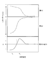
- FIG. 1 shows the temperature dependence of retardation ⁇ when the pre-stretched film is stretched, and the temperature dependence of retardation ⁇ when the layers (A) and (B) of the pre-stretched film are stretched. It is a figure which shows an example.
- intrinsic birefringence being positive means that the refractive index in the stretching direction is larger than the refractive index in the direction perpendicular thereto unless otherwise noted.
- negative intrinsic birefringence means that the refractive index in the stretching direction is smaller than the refractive index in the direction perpendicular to the stretching direction unless otherwise specified.
- the value of intrinsic birefringence can be calculated from the dielectric constant distribution.
- retardation is a value represented by “(nx ⁇ ny) ⁇ d” unless otherwise specified.
- the plane orientation coefficient is a value represented by “(nx + ny) / 2 ⁇ nz” unless otherwise specified.
- the birefringence is a value represented by “nx ⁇ ny” unless otherwise specified.
- the Nz coefficient is a value represented by “(nx ⁇ nz) / (nx ⁇ ny)” unless otherwise specified.
- nx represents a refractive index in a direction (in-plane direction) perpendicular to the thickness direction and giving the maximum refractive index.
- ny represents the refractive index in the in-plane direction and perpendicular to the nx direction.
- nz represents the refractive index in the thickness direction.
- d represents the thickness. Unless otherwise noted, the measurement wavelength of these refractive indices nx, ny and nz is 532 nm.
- the slow axis of the film or layer represents the in-plane slow axis unless otherwise specified.
- the “polarizing plate” includes not only a rigid member but also a flexible member such as a resin film.
- the direction of the component is “parallel”, “vertical” or “orthogonal”, unless otherwise specified, it is within a range not impairing the effect of the present invention, for example, usually ⁇ 5 °, preferably ⁇ 2 °, Preferably, an error within a range of ⁇ 1 ° may be included.
- the MD direction is the film flow direction in the production line, and usually coincides with the longitudinal direction and the longitudinal direction of the long film.
- the TD direction is a direction parallel to the film surface and perpendicular to the MD direction, and usually coincides with the width direction and the lateral direction of a long film.
- the “long” means one having a length of 5 times or more with respect to the width, preferably 10 times or more, and specifically wound in a roll shape. It has a length that can be stored or transported.
- the optical film of the present invention includes a layer (A) made of a resin (a) containing polycarbonate. Moreover, the optical film of this invention may be equipped with layers other than a layer (A). For example, when performing viewing angle compensation of a polarizing plate using the optical film of the present invention, the optical film of the present invention includes a layer (B) made of a resin (b) different from the resin (a). Is preferred.
- the resin (a) forming the layer (A) contains polycarbonate.
- Polycarbonate is a polymer having a carbonate unit, and is excellent in retardation development, low temperature stretchability, and adhesion to other layers.
- the carbonate unit is a structural unit containing a carbonate bond (—O—C ( ⁇ O) —O—), and examples thereof include a structural unit of the following formula (I).
- R 0 represents a divalent hydrocarbon group.
- R 1 to R 8 each independently represents a hydrogen atom, a halogen atom, an alkyl group, a cycloalkyl group, or an aryl group.
- the alkyl group, cycloalkyl group, and aryl group may be substituted or unsubstituted.
- the alkyl group usually has 1 to 10 carbon atoms
- the cycloalkyl group usually has 1 to 10 carbon atoms
- the aryl group usually has 1 to 10 carbon atoms.
- R 1 to R 8 are the same as those in the formula (I).
- R 9 represents a hydrogen atom, an alkyl group or an aryl group.
- the number of carbon atoms of the alkyl group is usually 1 to 9
- the number of carbon atoms of the aryl group is usually 1 to 9.
- Z is a residue capable of forming a saturated or unsaturated hydrocarbon ring having 4 to 11 carbon atoms together with the carbon atom to which it is bonded.
- the hydrocarbon ring is preferably a saturated hydrocarbon ring having 6 carbon atoms.
- R 1 to R 8 are the same as those in the formula (I).
- carbonate units preferred examples include the following.
- polycarbonate one containing one type of carbonate unit may be used, or one containing two or more types of carbonate units combined at an arbitrary ratio may be used.
- the polycarbonate may contain an arbitrary structural unit in addition to the carbonate unit.
- the proportion of the carbonate unit is preferably 55% by weight or more, more preferably 70% by weight or more, and particularly preferably 90% by weight or more from the viewpoint of effectively exhibiting the advantages of the polycarbonate.
- suitable polycarbonates include bisphenol A polycarbonate, branched bisphenol A polycarbonate, o, o, o ′, o′-tetramethylbisphenol A polycarbonate, and the like. Moreover, a polycarbonate may be used individually by 1 type and may be used combining two or more types by arbitrary ratios.
- the amount of the phenolic hydroxyl group contained in the polycarbonate is usually 0.005 mol or less, preferably 0.003 mol or less, more preferably 0.002 mol or less with respect to 1 mol of the main chain carbonate unit of the polycarbonate. Ideally 0 mol.
- the phenolic hydroxyl group represents a hydroxyl group directly bonded to the benzene ring.
- the main chain carbonate unit represents a carbonate unit contained in the main chain of the polycarbonate.
- the thickness of the layer (A) is as thin as 10 ⁇ m or less, the occurrence of optical defects in the layer (A) can be suppressed.
- the present invention is not limited by the following inference.
- the resin (a) is formed into a film by a melt extrusion method
- the resin (a) is in a molten state.
- the resin (a) is at a high temperature not lower than the glass transition temperature.
- the melt extrusion method generally takes a longer time for the resin (a) to remain in a molten state at a high temperature than other methods such as an injection molding method.
- the phenolic hydroxyl groups may react to increase the molecular weight, thereby causing the polycarbonate to gel.
- the physical properties of the resin (a) change, and the generated gel becomes a fish eye, which may contribute to optical defects.
- gelation is unlikely to occur, and it is assumed that optical defects caused by this gelation can be prevented.
- the amount of the phenolic hydroxyl group contained in the polycarbonate relative to 1 mol of the main chain carbonate unit of the polycarbonate can be measured by 1 H-NMR.
- the resin (a) may contain an optional component other than polycarbonate as long as the effects of the present invention are not significantly impaired.
- the resin (a) may contain a polymer other than polycarbonate, a compounding agent, and the like.
- polymers other than polycarbonate that can be contained in the resin (a) include acrylic polymers such as polymethyl methacrylate; olefin polymers such as polyethylene and polypropylene; polyesters such as polyethylene terephthalate and polybutylene terephthalate; polyphenylene sulfide and the like.
- the amount of the polymer other than polycarbonate is small in the resin (a) from the viewpoint of effectively utilizing the advantages of the polycarbonate.
- the amount of the polymer other than polycarbonate is preferably 10 parts by weight or less, more preferably 5 parts by weight or less, and still more preferably 3 parts by weight or less with respect to 100 parts by weight of polycarbonate.
- compounding agents that can be contained in the resin (a) include lubricants; layered crystal compounds; inorganic fine particles; stabilizers such as antioxidants, heat stabilizers, light stabilizers, weathering stabilizers, ultraviolet absorbers; Agents, plasticizers, coloring agents such as dyes and pigments, antistatic agents, and the like.
- a lubricant and an ultraviolet absorber are preferable because they can improve the flexibility and weather resistance of the optical film.
- a compounding agent may be used individually by 1 type, and may be used combining two or more types by arbitrary ratios.
- the lubricant examples include inorganic particles such as silicon dioxide, titanium dioxide, magnesium oxide, calcium carbonate, magnesium carbonate, barium sulfate, strontium sulfate; polymethyl acrylate, polymethyl methacrylate, polyacrylonitrile, polystyrene, cellulose acetate, cellulose acetate pro Organic particles such as pionate can be mentioned. Among these, organic particles are preferable as the lubricant.
- ultraviolet absorbers examples include oxybenzophenone compounds, benzotriazole compounds, salicylic acid ester compounds, benzophenone ultraviolet absorbers, benzotriazole ultraviolet absorbers, acrylonitrile ultraviolet absorbers, triazine compounds, nickel complex compounds. And inorganic powders.
- UV absorbers include 2,2′-methylenebis (4- (1,1,3,3-tetramethylbutyl) -6- (2H-benzotriazol-2-yl) phenol), 2- (2′-hydroxy-3′-tert-butyl-5′-methylphenyl) -5-chlorobenzotriazole, 2,4-di-tert-butyl-6- (5-chlorobenzotriazol-2-yl) ) Phenol, 2,2′-dihydroxy-4,4′-dimethoxybenzophenone, 2,2 ′, 4,4′-tetrahydroxybenzophenone and the like. Particularly preferred are 2,2′-methylenebis ( 4- (1,1,3,3-tetramethylbutyl) -6- (2H-benzotriazol-2-yl) phenol).
- the amount of the compounding agent can be appropriately determined as long as the effects of the present invention are not significantly impaired.
- the amount of the compounding agent may be within a range where the total light transmittance in terms of 1 mm thickness of the optical film can be maintained at 80% or more.
- the glass transition temperature Tg (a) of the resin (a) is usually 147 ° C. or higher, preferably 150 ° C. or higher.
- the glass transition temperature Tg (a) is usually 147 ° C. or higher, preferably 150 ° C. or higher.
- the elongation at break of the resin (a) at the glass transition temperature Tg (b) of the resin (b) is preferably 50% or more, and 80% or more. More preferably. Although there is no restriction
- the elongation at break can be determined by using a test piece of test piece type 1B described in JIS K 7127 at a pulling speed of 100 mm / min.
- the optical film of the present invention can suppress the occurrence of optical defects in the layer (A). Therefore, the number of optical defects in the layer (A) is small. Specifically, the number of optical defects in the layer (A) per unit area is usually 0.1 / m 2 or less, preferably 0.06 / m 2 or less, more preferably 0.03 / m 2. 2 or less, ideally zero.
- the thickness of the layer (A) is 10 ⁇ m or less.
- the thickness of the layer (A) is so thin, conventionally, optical defects such as fish eyes were easily generated in the layer (A). However, in the optical film of the present invention, such optical defects are not generated. Can be suppressed.
- the lower limit of the thickness of the layer (A) is usually 0.2 ⁇ m or more, preferably 0.5 ⁇ m or more, more preferably 1.0 ⁇ m or more.
- the layer (A) can have birefringence.
- the birefringence value is preferably 0.002 or more, more preferably 0.004 or more.
- the variation in the slow axis of the layer (A) is small.
- the variation of the slow axis of the layer (A) is preferably within ⁇ 1 °, more preferably within ⁇ 0.5 °, particularly preferably within ⁇ 0.3 °, ideally Zero.
- the Nz coefficient of the layer (A) is preferably 10 or less, more preferably 5 or less. By setting the Nz coefficient of the layer (A) within the above range, it is easy to reduce the variation of the slow axis of the layer (A).
- the lower limit value of the Nz coefficient of the layer (A) can be 1 or more, but is usually 1.5 or more from the viewpoint of industrial production.
- the plane orientation coefficient of the layer (A) is preferably larger than 0.025, more preferably 0.026 or more, preferably 0.035 or less, more preferably 0.030 or less.
- the optical film of the present invention may have only one layer (A) or two or more layers.
- the optical film of the present invention may be a multilayer film having the first layer (A), the layer (B), and the second layer (A) in this order.
- the layer (A) is preferably on the outermost surface of the optical film of the present invention.
- an optical defect can be caused by a depression or protrusion on the surface of the layer (A)
- the depression or protrusion is a layer covering the surface of the layer (A). It may be buried to prevent the appearance of optical defects.
- the layer (A) is on the outermost surface, the depressions or protrusions are not filled with another layer, so conventionally it has been particularly difficult to prevent the occurrence of optical defects.
- the generation of the depressions and protrusions can be suppressed, the generation of optical defects can be effectively suppressed even when the layer (A) is on the outermost surface.
- the resin (b) is preferably a thermoplastic resin.
- the polymer contained in the resin (b) include a styrene or a homopolymer of a styrene derivative, and a polystyrene polymer including a copolymer of styrene or a styrene derivative and an arbitrary monomer; a polyacrylonitrile polymer.
- styrene or a styrene derivative acrylonitrile, maleic anhydride, methyl methacrylate, and butadiene are mentioned as a preferable thing, for example.
- these polymers may be used individually by 1 type, and may be used combining two or more types by arbitrary ratios.
- a polymer having at least one of a styrene unit and a methyl methacrylate unit is preferable.
- the styrene unit is a structural unit having a structure formed by polymerizing styrene.
- the methyl methacrylate unit is a structural unit having a structure formed by polymerizing methyl methacrylate.
- a polystyrene polymer is particularly preferable from the viewpoint of high retardation development.
- the amount of the structural unit having a structure formed by polymerizing maleic anhydride is preferably 5 parts by weight or more, more preferably 10 parts by weight or more, particularly preferably 100 parts by weight of the polystyrene polymer. Is 15 parts by weight or more, preferably 30 parts by weight or less, more preferably 28 parts by weight or less, and particularly preferably 26 parts by weight or less.
- the resin (b) may contain an optional component other than the polymer as long as the effects of the present invention are not significantly impaired.
- the resin (b) may contain a compounding agent or the like.
- Examples of the compounding agent that can be contained in the resin (b) include those in the same range as those described as the compounding agent that the resin (a) can contain. Moreover, these may be used individually by 1 type and may be used combining two or more types by arbitrary ratios.
- the amount of the compounding agent can be appropriately determined as long as the effects of the present invention are not significantly impaired. For example, the amount of the compounding agent may be within a range where the total light transmittance in terms of 1 mm thickness of the optical film can be maintained at 80% or more.
- the glass transition temperature Tg (b) of the resin (b) is usually 80 ° C. or higher, preferably 90 ° C. or higher, more preferably 100 ° C. or higher, still more preferably 110 ° C. or higher, and particularly preferably 120 ° C. or higher. Since the glass transition temperature Tg (b) is thus high, the relaxation of the orientation of the resin (b) can be reduced. Moreover, although there is no restriction
- the glass transition temperature Tg (b) of the resin (b) is equal to the glass transition temperature Tg (a) of the resin (a). Even if the difference Tg (a) ⁇ Tg (b) from the glass transition temperature Tg (b) of the resin (b) is set to satisfy the relationship of “Tg (a) ⁇ Tg (b)> 20 ° C.” Good. More specifically, Tg (a) -Tg (b) may be preferably greater than 20 ° C, more preferably greater than 22 ° C. Thereby, when it is desired to develop retardation in the optical film of the present invention by stretching, the temperature dependency of the development of retardation can be increased during stretching.
- the molecular chains contained in the layer (A) and the layer (B) can be largely oriented by stretching. Therefore, the thickness of the optical film after stretching can be reduced.
- the upper limit of the temperature difference Tg (a) ⁇ Tg (b) is preferably 50 ° C. or less, more preferably 40 ° C. or less, and particularly preferably 30 ° C. or less. Thereby, it is easy to improve the flatness of the optical film.
- the breaking elongation of the resin (b) at the glass transition temperature Tg (a) of the resin (a) is preferably 50% or more, and more preferably 80% or more. Although there is no restriction
- the thickness of the layer (B) is usually 10 ⁇ m or more, preferably 15 ⁇ m or more, more preferably 20 ⁇ m or more, and usually 100 ⁇ m or less, preferably 60 ⁇ m or less, more preferably 40 ⁇ m or less.
- the layer (B) can have birefringence.
- the birefringence value is preferably 0.004 or more, more preferably 0.005 or more, preferably 0.010 or less, more preferably 0.008 or less. is there.
- the birefringence of the layer (B) is not less than the lower limit of the above range, the thickness of the optical film is reduced when the optical film satisfies the relationship of 0.92 ⁇ R 40 /Re ⁇ 1.08. Is possible.
- the Nz coefficient of the layer (B) is preferably ⁇ 0.30 or more, more preferably ⁇ 0.25 or more. By setting the Nz coefficient of the layer (B) in the above range, when the optical film satisfies the relationship of 0.92 ⁇ R 40 /Re ⁇ 1.08, it is possible to reduce the thickness of the optical film. .
- the upper limit may be 0 or less, but is usually ⁇ 0.10 or less from the viewpoint of industrial production.
- the plane orientation coefficient of the layer (B) is preferably ⁇ 0.002 or less, more preferably ⁇ 0.003 or less.
- the optical film of the present invention may have only one layer (B) or two or more layers.
- the optical film of the present invention may further include an arbitrary layer in addition to the layer (A) and the layer (B).
- the optional layer include a mat layer capable of improving the slipperiness of the film, a hard coat layer such as an impact-resistant polymethacrylate resin layer, an antireflection layer, and an antifouling layer.
- optical film of the present invention can have desired optical properties depending on the application.
- the optical film may be an optically isotropic film having substantially no retardation.
- the optical film may be a film having optical anisotropy having a retardation of a desired size.
- the optical film of the present invention when used as a viewing angle compensation film in an image display device, the optical film preferably satisfies 0.92 ⁇ R 40 /Re ⁇ 1.08.
- Re represents retardation at an incident angle of 0 ° of the optical film.
- R 40 represents retardation at an incident angle of 40 ° of the optical film.
- the total light transmittance of the optical film of the present invention is preferably 85% or more.
- the light transmittance can be measured using a spectrophotometer (manufactured by JASCO Corporation, ultraviolet-visible near-infrared spectrophotometer “V-570”) in accordance with JIS K0115.
- the haze of the optical film of the present invention is preferably 5% or less, more preferably 3% or less, and particularly preferably 1% or less.
- the clarity of the display image of the display device including the optical film can be improved.
- the haze can be measured at five locations using “turbidity meter NDH-300A” manufactured by Nippon Denshoku Industries Co., Ltd. in accordance with JIS K7361-1997, and the average value obtained therefrom can be adopted.
- ⁇ YI is preferably 5 or less, and more preferably 3 or less. When this ⁇ YI is in the above range, there is no coloring and the visibility is good.
- the lower limit is ideally zero.
- ⁇ YI can be measured using “Spectral Color Difference Meter SE2000” manufactured by Nippon Denshoku Industries Co., Ltd. according to ASTM E313. The same measurement is performed five times, and the arithmetic average value is obtained.
- the optical film of the present invention preferably has a JIS pencil hardness of H or higher.
- This JIS pencil hardness can be adjusted by the type of resin and the thickness of the resin layer.
- the JIS pencil hardness is determined by tilting a pencil of various hardnesses by 45 °, applying a load of 500 g weight from above, scratching the film surface, and starting scratching. That's it.
- the optical film of the present invention may shrink in the longitudinal direction and the transverse direction by heat treatment at a temperature of 60 ° C., a humidity of 90% RH, and 100 hours.
- the shrinkage rate is preferably 0.5% or less, more preferably 0.3% or less.
- the dimension in the width direction of the optical film of the present invention is preferably 500 mm or more, more preferably 1000 mm or more, and preferably 2000 mm or less.
- the optical film of the present invention can be produced by a melt extrusion method.
- the melt extrusion method is an excellent production method from the viewpoints of production efficiency and that a volatile component such as a solvent does not remain in the film.
- a coextrusion method can be used in the melt extrusion method.
- the coextrusion method include a coextrusion T-die method, a coextrusion inflation method, and a coextrusion lamination method.
- the coextrusion T-die method is preferable.
- the coextrusion T-die method includes a feed block method and a multi-manifold method, and the multi-manifold method is particularly preferable in that variation in thickness can be reduced.
- the method for producing an optical film of the present invention includes a step of heating and melting the resin (a), and a step of extruding the molten resin (a) from a die into a film. Furthermore, when manufacturing an optical film provided with a layer (B), the manufacturing method of an optical film includes the process of heating and fuse
- the melting temperature of the resin (a) is preferably Tg (a) + 80 ° C. or higher, more preferably Tg (a) + 100 ° C. or higher, preferably Tg (a) + 180 ° C.
- it is more preferably Tg (a) + 150 ° C. or less.
- the residence time from when the resin (a) is melted until it is discharged from the die is preferably 5 hours or less, more preferably 3 hours or less, and particularly preferably 2 hours or less.
- a film-like molten resin extruded from an opening of a die is usually brought into close contact with a cooling roll (including a cooling drum).
- a cooling roll including a cooling drum
- the method for bringing the resin into close contact with the cooling roll include an air knife method, a vacuum box method, and an electrostatic contact method.
- the number of cooling rolls is not particularly limited, but is usually 2 or more.
- examples of the arrangement method of the cooling roll include, but are not particularly limited to, a linear type, a Z type, and an L type.
- the way of passing the resin extruded from the opening of the die through the cooling roll is not particularly limited.
- the degree of adhesion of the extruded film-like resin to the cooling roll varies depending on the temperature of the cooling roll. Increasing the temperature of the cooling roll tends to improve adhesion. Moreover, by not making the temperature of a cooling roll too high, peeling from the cooling roll of film-form resin can be made easy, and the winding of resin to a cooling roll can be prevented. From this point of view, the temperature of the cooling roll is preferably (Tg ′ + 30 ° C.) or less, more preferably (Tg ′ ⁇ ), where Tg ′ is the glass transition temperature of the resin extruded from the die and contacting the drum. 5 ° C.) to (Tg′ ⁇ 45 ° C.). Thereby, malfunctions, such as a slip and a crack, can be prevented.
- the residual solvent contained in the resin as a raw material is reduced; (2) before the film is formed
- the resin may be pre-dried.
- the preliminary drying is performed using, for example, a hot air dryer or the like in the form of pellets or the like.
- the drying temperature is preferably 100 ° C. or more, and the drying time is preferably 2 hours or more.
- the optical film of the present invention is obtained by the melt extrusion method.
- the optical film obtained in this way does not develop a large retardation. Therefore, for example, in order to express a desired retardation, the obtained optical film may be stretched. Therefore, in the following, an example of producing an optical film having the layer (A) and the layer (B) and satisfying 0.92 ⁇ R 40 /Re ⁇ 1.08 will be described.
- stretching process in a manufacturing method is demonstrated.
- an optical film before being subjected to stretching treatment may be appropriately referred to as “film before stretching” and an optical film that has been subjected to stretching treatment as “stretched film”.
- the film before stretching in the example shown here is a film including a layer (A) made of the resin (a) and a layer (B) made of the resin (b).
- This pre-stretched film satisfies the following requirement P in order to obtain a film satisfying 0.92 ⁇ R 40 /Re ⁇ 1.08 as a stretched film.
- Requirement P When the uniaxial stretching direction is the X axis, the direction perpendicular to the uniaxial stretching direction in the film plane is the Y axis, and the film thickness direction is the Z axis, the phase of the XZ polarized light with respect to the YZ polarized light is Delayed when uniaxially stretched in the X-axis direction at temperature T1, The process proceeds when uniaxial stretching is performed in the X-axis direction at a temperature T2 different from the temperature T1.
- XZ polarized light refers to linearly polarized light that is incident perpendicularly to the film surface and has an electric vector vibration plane in the XZ plane.
- YZ polarized light refers to linearly polarized light that is incident perpendicularly to the film surface and the vibration plane of the electric vector is on the YZ plane.
- the pre-stretch film is an isotropic (that is, has no anisotropy) raw film, so if one of the in-plane directions is taken as the X-axis, any other direction can be satisfied.
- the requirement P can also be satisfied when is the X axis.
- the phase of XZ polarized light is usually delayed from that of YZ polarized light.
- the phase of XZ polarized light usually proceeds with respect to that of YZ polarized light.
- the pre-stretch film satisfying the above requirement P is a film using these properties, and the slow axis or fast axis appears depending on the stretch temperature.
- the temperature dependence of the expression of such retardation can be adjusted, for example, by adjusting the relationship such as the photoelastic coefficient of the resin contained in the pre-stretched film and the thickness ratio of each layer.
- the retardation ⁇ that can be expressed in the entire pre-stretched film when the pre-stretched film is stretched is synthesized from the retardation ⁇ that is expressed in each resin layer included in the pre-stretched film.
- Temperature T1 of the requirements P is a temperature either temperature T H or T L
- the temperature T2 is the other of the temperature of different temperatures T H or T L is the temperature T1.
- the temperature satisfying the requirement P is preferably (Tg 1 ⁇ 10 ° C.) to (Tg h + 10 ° C.) because the birefringence can be easily adjusted. That is, the temperatures T1 and T2 are preferably included in the temperature range of (Tg 1 ⁇ 10 ° C.) to (Tg h + 10 ° C.).
- the temperature Tg l in the resin contained in the film before stretching, most glass transition temperature means a glass transition temperature of the resin having low.
- the temperature Tg h and, among the resin contained in the film before stretching, most glass transition temperature means a glass transition temperature of the high resin.
- FIG. 1 shows the temperature dependence of retardation ⁇ when the pre-stretched film is stretched, and the temperature dependence of retardation ⁇ when the layers (A) and (B) of the pre-stretched film are stretched. It is a figure which shows an example. In the example shown in FIG. 1, the glass transition temperature of the resin (a) is high, and the glass transition temperature of the resin (b) is low.
- the negative retardation ⁇ expressed in the layer (B) is larger than the positive retardation ⁇ expressed in the layer (A). Overall, a negative retardation ⁇ is developed.
- the negative retardation ⁇ expressed in the layer (B) is smaller than the positive retardation ⁇ expressed in the layer (A), so that the positive retardation ⁇ is expressed as a whole. To do. Therefore, by combining such stretching at different temperatures Ta and Tb, a retardation ⁇ generated by stretching at each temperature is synthesized, and a stretched film having a desired retardation ⁇ and thus exhibiting desired optical properties. Can be realized stably.
- the resin contained in the pre-stretch film is a resin that can cause a difference between the refractive index in the X-axis direction and the refractive index in the Y-axis direction in each layer by stretching in one direction (that is, uniaxial stretching).
- a pre-stretched film satisfying the above requirement P can be obtained.
- a resin having a large degree of orientation developed by stretching is used, a large retardation ⁇ can be expressed even if the layer thickness is reduced.
- the specific thickness of the layer constituting the pre-stretched film can be set according to the optical properties of the stretched film to be manufactured so as to satisfy the requirement P described above.
- the ratio TA / TB of the total thickness TA of the layer (A) and the total thickness TB of the layer (B) is preferably 1/20 or more, more preferably 1/15 or more, preferably 1/4 or less, more preferably 1/5 or less.
- a stretching process for stretching the pre-stretching film is performed.
- each layer included in the pre-stretching film is also stretched, and the stretched layers exhibit predetermined optical characteristics.
- the film before stretching is subjected to a uniaxial stretching process in one direction at one of the temperatures T1 and T2, and a direction orthogonal to the direction in which the uniaxial stretching process is performed in the first stretching process, And a second stretching step in which a uniaxial stretching process is performed at the other temperature of T1 and T2.
- the film before stretching is uniaxially stretched in one direction at one of the temperatures T1 and T2.
- the phase of the XZ polarized light with respect to the YZ polarized light is delayed in the pre-stretched film that satisfies the requirement P.
- the uniaxial stretching is performed at the temperature T2
- the phase of the XZ polarized light with respect to the YZ polarized light advances.
- the temperature T1 is preferably higher than Tg (b), more preferably higher than Tg (b) + 5 ° C, preferably lower than Tg (a) + 40 ° C, and lower than Tg (a) + 20 ° C. Is more preferable.
- the optical characteristics of the layer (B) can be stably kept within a desired range.
- the optical characteristic of a layer (A) can be stably stored in a desired range.
- the stretching ratio in the first stretching step is preferably 2 times or more, more preferably 3 times or more, preferably 4 times or less, more preferably 3.5 times or less.
- the uniaxial stretching process can be performed by a known method.
- a method of uniaxially stretching in the MD direction using a difference in peripheral speed between rolls; a method of uniaxially stretching in the TD direction using a tenter, and the like can be mentioned.
- Examples of the method of uniaxially stretching in the MD direction include an IR heating method between rolls, a float method, and the like. Of these, the float method is preferable because a stretched film having high optical uniformity can be obtained.
- a tenter method can be mentioned as a method of uniaxially stretching in the TD direction.
- a temperature difference may be created in the TD direction of the film in the stretching zone.
- a method of adjusting the opening degree of the hot air nozzle in the TD direction or controlling the heating by arranging the IR heaters in the TD direction can be used.
- a 2nd extending process is performed.
- the film subjected to the uniaxial stretching process in one direction in the first stretching process is subjected to a uniaxial stretching process in a direction orthogonal to the direction in which the uniaxial stretching process is performed in the first stretching process.
- the uniaxial stretching process in the second stretching step is performed at a temperature different from the stretching temperature in the first stretching step among the temperatures T1 and T2. In the second stretching step, it is preferable to perform a uniaxial stretching process at a temperature T2.
- the temperature T2 is usually a temperature lower than the temperature T1.
- the specific temperature T2 is preferably higher than Tg (b) ⁇ 20 ° C., more preferably higher than Tg (b) ⁇ 10 ° C., preferably lower than Tg (b) + 5 ° C., and Tg (b b) is preferably lower.
- Tg (b b) is preferably lower.
- the difference between the temperature T1 and the temperature T2 is usually 10 ° C. or higher, preferably 20 ° C. or higher.
- desired optical characteristics can be stably expressed in the stretched film.
- 100 degrees C or less is preferable from a viewpoint of industrial productivity.
- the stretching ratio in the second stretching step is preferably smaller than the stretching ratio in the first stretching step.
- the state of molecular orientation in the stretched film obtained tends to be more strongly influenced in the second stretching step than in the first stretching step. Therefore, adjustment of the optical characteristic of a stretched film is easy, so that the draw ratio of a 2nd extending process is small.
- the stretching ratio in the specific second stretching step is preferably 1.1 times or more, preferably 2 times or less, more preferably 1.5 times or less, and particularly preferably 1.3 times or less.
- the stretching ratio is high in both the first stretching step and the second stretching step.
- the product of the draw ratio in the first draw step and the draw ratio in the second draw step is preferably 3.6 or more, more preferably 3.8 or more, and even more preferably 4.0 or more. is there.
- the upper limit of the product of the draw ratio in the first draw step and the draw ratio in the second draw step is preferably 6.0 or less from the viewpoint of facilitating adjustment of optical properties in the draw step.
- the same method as that which can be adopted in the uniaxial stretching process in the first stretching process can be applied to the uniaxial stretching process in the second stretching process.
- the combination of the stretching directions in the first stretching process and the second stretching process is arbitrary.
- the film may be stretched in the MD direction in the first stretching process and stretched in the TD direction in the second stretching process.
- the film may be stretched in the TD direction in the first stretching process and stretched in the MD direction in the second stretching process.
- the film may be stretched in an oblique direction in the first stretching process, and may be stretched in an oblique direction orthogonal to the second stretching process.
- the oblique direction represents a direction that is neither parallel nor perpendicular to the width direction of the film.
- the method for producing an optical film of the present invention may include a step of heat-treating the film at a predetermined temperature after the first stretching step or after the second stretching step.
- the temperature of the heat treatment is preferably Tg (b) -30 ° C. or more, more preferably Tg (b) -20 ° C. or more, preferably Tg (b) or less, more preferably Tg (b) ⁇ 5 ° C. or less. is there.
- the method for producing an optical film of the present invention may include a step (preheating step) of preheating the pre-stretching film before the stretching step.
- the heating means include an oven-type heating device, a radiation heating device, or immersion in a liquid. Of these, an oven-type heating device is preferable.
- the heating temperature in this step is preferably a stretching temperature of ⁇ 40 ° C. or more, more preferably a stretching temperature of ⁇ 30 ° C. or more, preferably a stretching temperature of + 20 ° C. or less, more preferably a stretching temperature of + 15 ° C. or less.
- the stretching temperature means a set temperature of the heating device.
- the method for producing an optical film of the present invention may further include a step of further providing an arbitrary layer on the surface of the film obtained as described above.
- optical film of the present invention is arbitrary.
- the optical film of the present invention can be used for, for example, a viewing angle compensation film, a polarizing plate protective film, and the like.
- Example 1 [Example 1] [1. Production and evaluation of stretched film) A polycarbonate resin (“Iupilon S3000” manufactured by Mitsubishi Engineering Plastics, glass transition temperature 149 ° C.) was prepared as the resin (a). The amount of the phenolic hydroxyl group of the polycarbonate contained in this polycarbonate resin is 0.0016 mol with respect to 1 mol of the main chain carbonate unit of the polycarbonate. Further, a styrene / maleic anhydride copolymer resin (“Dialark D332” manufactured by Nova Chemicals, glass transition temperature 128 ° C) was prepared as the resin (b).
- a polycarbonate resin (“Iupilon S3000” manufactured by Mitsubishi Engineering Plastics, glass transition temperature 149 ° C.) was prepared as the resin (a). The amount of the phenolic hydroxyl group of the polycarbonate contained in this polycarbonate resin is 0.0016 mol with respect to 1 mol of the main chain carbonate unit of the polycarbonate. Further, a st
- a film forming apparatus for coextrusion molding of two types and two layers (layer (A) / layer (B)) was prepared. This film forming apparatus is provided with a single screw extruder for each of the layer (A) and the layer (B).
- the resin (a) was supplied to a single screw extruder for the layer (A) of the film forming apparatus and melted at 270 ° C.
- the molten resin (a) was supplied to the manifold for the layer (A) of the multi-manifold die through 20 4.4 inch leaf disk filters having a filtration accuracy of 5 ⁇ m.
- the resin (b) was supplied to a uniaxial stretching machine for the layer (B) of the film forming apparatus and melted at 260 ° C.
- the molten resin (b) was supplied to the manifold for the layer (B) of the multi-manifold die through 50 12 inch leaf disk filters having a filtration accuracy of 5 ⁇ m.
- the resin (a) and the resin (b) were simultaneously extruded from the multi-manifold die and formed into a film shape. At this time, the extrusion rate of the resin (a) was 20 kg / hour, and the extrusion rate of the resin (b) was 200 kg / hour. This obtained the elongate multilayer film provided with the layer (A) which consists of resin (a) with a thickness of 20 micrometers, and the layer (B) which consists of resin (b) with a thickness of 200 micrometers.
- the above multilayer film was stretched in the width direction at a stretching temperature of 160 ° C. and a stretching ratio of 3.0 times using a transverse stretching machine to obtain an intermediate film. Thereafter, this intermediate film was stretched in the longitudinal direction using a longitudinal stretching machine at a stretching temperature of 125 ° C. and a stretching ratio of 1.3 times to obtain a stretched film.
- the layer (A) of the obtained stretched film had a thickness of 7 ⁇ m, and the layer (B) had a thickness of 67 ⁇ m.
- the surface of the stretched film thus obtained was washed with pure water. Thereafter, the stretched film was sandwiched between two polarizing plates to produce a sample sheet having a polarizing plate / stretched film / polarizing plate in this order. At this time, the polarizing plates were arranged in crossed Nicols so that the polarization transmission axes of the polarizing plates were perpendicular to each other.
- the sample sheet was illuminated with a backlight, and the side opposite to the backlight of the data sheet was observed to count the number of bright spots. Since the bright spots are caused by optical defects, a stretched film having a smaller number of bright spots is used as a high-quality optical film with fewer optical defects.
- a coloring resin was prepared by adding 1% by weight of a pigment (“Kayaset Red ECG” manufactured by Nippon Kayaku Co., Ltd.) to the polycarbonate resin prepared as the resin (a). This colored resin was filled from the single screw extruder for the layer (A) of the film forming apparatus to the multi-manifold die. Thereafter, the polycarbonate resin containing no dye was put into a single screw extruder for the layer (A) and extruded at an extrusion speed of 20 kg / hour. The time from the start of extrusion until the dye concentration of the resin discharged from the multi-manifold die became 1 ppm or less was measured, and this was defined as the longest residence time.
- a pigment Korean ECG manufactured by Nippon Kayaku Co., Ltd.
- Example 2 The kind of polycarbonate resin used as the resin (a) was changed to “Taflon A1900” (glass transition temperature 149 ° C.) manufactured by Idemitsu Kosan Co., Ltd.
- the amount of the phenolic hydroxyl group of the polycarbonate contained in the polycarbonate resin used in Example 2 is 0.0029 mol with respect to 1 mol of the main chain carbonate unit of the polycarbonate. Except for the above, the production and evaluation of a stretched film and the measurement of the longest residence time of the polycarbonate resin were performed in the same manner as in Example 1.
Abstract
An optical film provided with a layer (A) comprising a resin (a) including polycarbonate, the thickness of the layer (A) being 10 µm or less, and the amount of phenolic hydroxyl groups included in the polycarbonate being 0.005 mol or less per 1 mol of main-chain carbonate units of the polycarbonate.
Description
本発明は、光学フィルム及びその製造方法に関する。
The present invention relates to an optical film and a method for producing the same.
ポリカーボネートを含むポリカーボネート樹脂は、透明性が高く、強靭であることから、光学用のディスク及びフィルムの原料として、広く使用されている(特許文献1及び2)。また、ポリカーボネート樹脂でフィルムを製造した場合、そのフィルムは延伸によって容易に複屈折を発現しうるので、位相差フィルムとして使用することができる。
Polycarbonate resins containing polycarbonate are widely used as raw materials for optical disks and films because of their high transparency and toughness (Patent Documents 1 and 2). Moreover, when a film is manufactured with a polycarbonate resin, the film can easily exhibit birefringence by stretching, and thus can be used as a retardation film.
ポリカーボネート樹脂を用いてフィルムを製造する場合、溶融押出法が用いられることがある。しかし、溶融押出法を用いた場合には、例えば射出成型法等の別の方法を用いた場合に比べ、フィッシュアイ等の光学欠陥が多く生じる傾向があった。ここでフィッシュアイとは、フィルムの内部に生じうる異物のことをいう。このような光学欠陥は、ポリカーボネート樹脂からなる層のみを備える単層構造のフィルムだけでなく、ポリカーボネート樹脂からなる層に加えて別の層を備える複層構造のフィルムでも生じうる。また、このような光学欠陥は、ポリカーボネート樹脂からなる層の厚さが10μm以下と薄い場合に、特に生じやすい。
When a film is produced using a polycarbonate resin, a melt extrusion method may be used. However, when the melt extrusion method is used, optical defects such as fish eyes tend to occur more than when another method such as an injection molding method is used. Here, the fish eye refers to foreign matters that can be generated inside the film. Such an optical defect may occur not only in a single-layer film having only a layer made of polycarbonate resin, but also in a multilayer film having another layer in addition to a layer made of polycarbonate resin. Such optical defects are particularly likely to occur when the thickness of the layer made of polycarbonate resin is as thin as 10 μm or less.
本発明は前記の課題に鑑みて創案されたもので、ポリカーボネートを含む樹脂(a)からなる厚み10μm以下の層(A)を備え、且つ、前記の層(A)において光学欠陥の発生を抑制できる光学フィルム;並びに、その光学フィルムの製造方法;を提供することを目的とする。
The present invention was devised in view of the above problems, and includes a layer (A) having a thickness of 10 μm or less made of a resin (a) containing polycarbonate, and suppresses the occurrence of optical defects in the layer (A). It is an object of the present invention to provide an optical film that can be produced, and a method for producing the optical film.
本発明者は、上述した課題を解決するべく鋭意検討した結果、ポリカーボネートの主鎖カーボネート単位1molに対するフェノール性水酸基の量が0.005mol以下であるポリカーボネートを含む樹脂(a)を用いることにより、当該樹脂(a)からなる層(A)の光学欠陥の発生を抑制できることを見出し、本発明を完成させた。
すなわち、本発明は以下の通りである。 As a result of intensive studies to solve the above-mentioned problems, the present inventor used the resin (a) containing a polycarbonate having an amount of phenolic hydroxyl group of 0.005 mol or less with respect to 1 mol of the main chain carbonate unit of the polycarbonate. The inventors have found that generation of optical defects in the layer (A) made of the resin (a) can be suppressed, and completed the present invention.
That is, the present invention is as follows.
〔1〕 ポリカーボネートを含む樹脂(a)からなる層(A)を備え、
前記層(A)の厚さが、10μm以下であり、
前記ポリカーボネートに含まれるフェノール性水酸基の量が、前記ポリカーボネートの主鎖カーボネート単位1molに対して、0.005mol以下である、光学フィルム。
〔2〕 前記層(A)が、複屈折を有し
前記層(A)の遅相軸のばらつきが、±1°以内である、〔1〕記載の光学フィルム。
〔3〕 スチレン単位及びメチルメタクリレート単位の少なくとも一方を有する重合体を含む樹脂(b)からなる層(B)を備える、〔1〕又は〔2〕記載の光学フィルム。
〔4〕 〔1〕~〔3〕のいずれか一項に記載の光学フィルムの製造方法であって、
前記樹脂(a)を、前記樹脂(a)のガラス転移温度Tg(a)+80℃以上の温度で溶融する工程と、
溶融した前記樹脂(a)を、ダイスからフィルム状に押出成形する工程とを含み、
前記樹脂(a)が溶融してから、前記ダイスから吐出されるまでの滞留時間が、5時間以下である、光学フィルムの製造方法。 [1] A layer (A) comprising a resin (a) containing polycarbonate,
The thickness of the layer (A) is 10 μm or less,
The optical film whose quantity of the phenolic hydroxyl group contained in the said polycarbonate is 0.005 mol or less with respect to 1 mol of main chain carbonate units of the said polycarbonate.
[2] The optical film according to [1], wherein the layer (A) has birefringence, and the variation of the slow axis of the layer (A) is within ± 1 °.
[3] The optical film according to [1] or [2], comprising a layer (B) comprising a resin (b) containing a polymer having at least one of a styrene unit and a methyl methacrylate unit.
[4] The method for producing an optical film according to any one of [1] to [3],
Melting the resin (a) at a temperature of the glass transition temperature Tg (a) + 80 ° C. of the resin (a);
A step of extruding the molten resin (a) from a die into a film,
The manufacturing method of the optical film whose residence time after the said resin (a) fuse | melts until it discharges from the said die | dye is 5 hours or less.
本発明によれば、ポリカーボネートを含む樹脂(a)からなる厚み10μm以下の層(A)を備え、且つ、前記の層(A)において光学欠陥の発生を抑制できる光学フィルム;並びに、その光学フィルムの製造方法を提供できる。
According to the present invention, an optical film comprising a layer (A) made of a resin (a) containing polycarbonate and having a thickness of 10 μm or less and capable of suppressing the occurrence of optical defects in the layer (A); and the optical film Can be provided.
以下、例示物及び実施形態を挙げて本発明について詳細に説明する。ただし、本発明は以下に挙げる例示物及び実施形態に限定されるものではなく、本発明の請求の範囲及びその均等の範囲を逸脱しない範囲において任意に変更して実施しうる。
Hereinafter, the present invention will be described in detail with reference to examples and embodiments. However, the present invention is not limited to the following examples and embodiments, and can be implemented with any modifications without departing from the scope of the claims and the equivalents thereof.
以下の説明において、固有複屈折が正であるとは、別に断らない限り、延伸方向の屈折率がそれに直交する方向の屈折率よりも大きくなることを意味する。また、固有複屈折が負であるとは、別に断らない限り、延伸方向の屈折率がそれに直交する方向の屈折率よりも小さくなることを意味する。固有複屈折の値は誘電率分布から計算することができる。
In the following description, the intrinsic birefringence being positive means that the refractive index in the stretching direction is larger than the refractive index in the direction perpendicular thereto unless otherwise noted. Further, negative intrinsic birefringence means that the refractive index in the stretching direction is smaller than the refractive index in the direction perpendicular to the stretching direction unless otherwise specified. The value of intrinsic birefringence can be calculated from the dielectric constant distribution.
また、以下の説明において、レターデーションとは、別に断らない限り、「(nx-ny)×d」で表される値である。さらに、面配向係数は、別に断らない限り、「(nx+ny)/2-nz」で表される値である。また、複屈折は、別に断らない限り、「nx-ny」で表される値である。さらに、Nz係数は、別に断らない限り、「(nx-nz)/(nx-ny)」で表される値である。ここで、nxは、厚み方向に垂直な方向(面内方向)であって最大の屈折率を与える方向の屈折率を表す。nyは、前記面内方向であってnxの方向に垂直な方向の屈折率を表す。nzは、厚み方向の屈折率を表す。dは、厚みを表す。別に断らない限り、これらの屈折率nx、ny及びnzの測定波長は、532nmである。
In the following description, retardation is a value represented by “(nx−ny) × d” unless otherwise specified. Further, the plane orientation coefficient is a value represented by “(nx + ny) / 2−nz” unless otherwise specified. The birefringence is a value represented by “nx−ny” unless otherwise specified. Further, the Nz coefficient is a value represented by “(nx−nz) / (nx−ny)” unless otherwise specified. Here, nx represents a refractive index in a direction (in-plane direction) perpendicular to the thickness direction and giving the maximum refractive index. ny represents the refractive index in the in-plane direction and perpendicular to the nx direction. nz represents the refractive index in the thickness direction. d represents the thickness. Unless otherwise noted, the measurement wavelength of these refractive indices nx, ny and nz is 532 nm.
また、フィルム又は層の遅相軸とは、別に断らない限り、面内の遅相軸を表す。
Also, the slow axis of the film or layer represents the in-plane slow axis unless otherwise specified.
また、「偏光板」とは、剛直な部材だけでなく、例えば樹脂製のフィルムのように可撓性を有する部材も含む。
The “polarizing plate” includes not only a rigid member but also a flexible member such as a resin film.
また、構成要素の方向が「平行」、「垂直」又は「直交」とは、別に断らない限り、本発明の効果を損ねない範囲内、例えば、通常±5°、好ましくは±2°、より好ましくは±1°の範囲内での誤差を含んでいてもよい。
Further, unless the direction of the component is “parallel”, “vertical” or “orthogonal”, unless otherwise specified, it is within a range not impairing the effect of the present invention, for example, usually ± 5 °, preferably ± 2 °, Preferably, an error within a range of ± 1 ° may be included.
また、MD方向(machine direction)は、製造ラインにおけるフィルムの流れ方向であり、通常は長尺のフィルムの長手方向及び縦方向に一致する。さらに、TD方向(traverse direction)は、フィルム面に平行な方向であって、MD方向に垂直な方向であり、通常は長尺のフィルムの幅方向及び横方向に一致する。また、「長尺」とは、幅に対して、5倍以上の長さを有するものをいい、好ましくは10倍若しくはそれ以上の長さを有し、具体的にはロール状に巻き取られて保管又は運搬される程度の長さを有するものをいう。
Also, the MD direction (machine direction) is the film flow direction in the production line, and usually coincides with the longitudinal direction and the longitudinal direction of the long film. Further, the TD direction (traverse direction) is a direction parallel to the film surface and perpendicular to the MD direction, and usually coincides with the width direction and the lateral direction of a long film. Further, the “long” means one having a length of 5 times or more with respect to the width, preferably 10 times or more, and specifically wound in a roll shape. It has a length that can be stored or transported.
[1.概要]
本発明の光学フィルムは、ポリカーボネートを含む樹脂(a)からなる層(A)を備える。また、本発明の光学フィルムは、層(A)以外の層を備えていてもよい。例えば、本発明の光学フィルムを用いて、偏光板の視野角補償を行う場合には、本発明の光学フィルムは、樹脂(a)とは異なる樹脂(b)からなる層(B)を備えることが好ましい。 [1. Overview]
The optical film of the present invention includes a layer (A) made of a resin (a) containing polycarbonate. Moreover, the optical film of this invention may be equipped with layers other than a layer (A). For example, when performing viewing angle compensation of a polarizing plate using the optical film of the present invention, the optical film of the present invention includes a layer (B) made of a resin (b) different from the resin (a). Is preferred.
[2.層(A)]
層(A)を形成する樹脂(a)は、ポリカーボネートを含む。ポリカーボネートは、カーボネート単位を有する重合体であり、レターデーションの発現性、低温での延伸性、および他層との接着性に優れる。ここで、カーボネート単位とは、カーボネート結合(-O-C(=O)-O-)を含む構造単位であり、例えば、下記式(I)の構造単位が挙げられる。 [2. Layer (A)]
The resin (a) forming the layer (A) contains polycarbonate. Polycarbonate is a polymer having a carbonate unit, and is excellent in retardation development, low temperature stretchability, and adhesion to other layers. Here, the carbonate unit is a structural unit containing a carbonate bond (—O—C (═O) —O—), and examples thereof include a structural unit of the following formula (I).

式(I)において、R0は、2価の炭化水素基を示す。
また、式(I)において、R1~R8は、それぞれ独立に、水素原子、ハロゲン原子、アルキル基、シクロアルキル基、またはアリール基を示す。また、アルキル基、シクロアルキル基及びアリール基は、置換されていてもよく、無置換でもよい。さらに、アルキル基の炭素原子数は、通常1~10であり、シクロアルキル基の炭素原子数は、通常1~10であり、アリール基の炭素原子数は、通常1~10である。 In the formula (I), R 0 represents a divalent hydrocarbon group.
In the formula (I), R 1 to R 8 each independently represents a hydrogen atom, a halogen atom, an alkyl group, a cycloalkyl group, or an aryl group. The alkyl group, cycloalkyl group, and aryl group may be substituted or unsubstituted. Further, the alkyl group usually has 1 to 10 carbon atoms, the cycloalkyl group usually has 1 to 10 carbon atoms, and the aryl group usually has 1 to 10 carbon atoms.
式(I)で表されるポリカーボネート単位のうちでも、下記式(II)で表されるカーボネート単位、及び、下記式(III)で表されるカーボネート単位が好ましい。
Among the polycarbonate units represented by the formula (I), carbonate units represented by the following formula (II) and carbonate units represented by the following formula (III) are preferable.

式(II)において、R1~R8は、式(I)と同様のものを表す。
式(II)において、R9は、水素原子、または、アルキル基若しくはアリール基を示す。ここで、アルキル基の炭素原子数は、通常1~9であり、アリール基の炭素原子数は、通常1~9である。
式(II)において、Zは、それが結合している炭素原子と一緒になって、炭素原子数4~11の飽和若しくは不飽和の炭化水素環を形成しうる残基である。中でも、前記炭化水素環としては、炭素原子数が6の飽和炭化水素環であることが好ましい。 In the formula (II), R 1 to R 8 are the same as those in the formula (I).
In the formula (II), R 9 represents a hydrogen atom, an alkyl group or an aryl group. Here, the number of carbon atoms of the alkyl group is usually 1 to 9, and the number of carbon atoms of the aryl group is usually 1 to 9.
In the formula (II), Z is a residue capable of forming a saturated or unsaturated hydrocarbon ring having 4 to 11 carbon atoms together with the carbon atom to which it is bonded. Among these, the hydrocarbon ring is preferably a saturated hydrocarbon ring having 6 carbon atoms.

式(III)において、R1~R8は、式(I)と同様のものを表す。
In the formula (III), R 1 to R 8 are the same as those in the formula (I).
前記のカーボネート単位のうち、好ましいものの例を挙げると、下記のものが挙げられる。
Among the carbonate units, preferred examples include the following.

ポリカーボネートとしては、1種類のカーボネート単位を含むものを用いてもよく、2種類以上のカーボネート単位を任意の比率で組み合わせて含むものを用いてもよい。
As the polycarbonate, one containing one type of carbonate unit may be used, or one containing two or more types of carbonate units combined at an arbitrary ratio may be used.
また、ポリカーボネートは、前記のカーボネート単位以外に、任意の構造単位を含んでいてもよい。ただし、ポリカーボネートにおいて、カーボネート単位の割合は、前記のポリカーボネートの利点を有効に発揮させる観点から、好ましくは55重量%以上、さらに好ましくは70重量%以上、特に好ましくは90重量%以上である。
Further, the polycarbonate may contain an arbitrary structural unit in addition to the carbonate unit. However, in the polycarbonate, the proportion of the carbonate unit is preferably 55% by weight or more, more preferably 70% by weight or more, and particularly preferably 90% by weight or more from the viewpoint of effectively exhibiting the advantages of the polycarbonate.
好適なポリカーボネートの例を挙げると、ビスフェノールAポリカーボネート、分岐ビスフェノールAポリカーボネート、o,o,o’,o’-テトラメチルビスフェノールAポリカーボネートなどが挙げられる。
また、ポリカーボネートは、1種類を単独で用いてもよく、2種類以上を任意の比率で組み合わせて用いてもよい。 Examples of suitable polycarbonates include bisphenol A polycarbonate, branched bisphenol A polycarbonate, o, o, o ′, o′-tetramethylbisphenol A polycarbonate, and the like.
Moreover, a polycarbonate may be used individually by 1 type and may be used combining two or more types by arbitrary ratios.
ただし、樹脂(a)において、ポリカーボネートに含まれるフェノール性水酸基の量は、ポリカーボネートの主鎖カーボネート単位1molに対して、通常0.005mol以下、好ましくは0.003mol以下、より好ましくは0.002mol以下であり、理想的には0molである。ここで、フェノール性水酸基とは、ベンゼン環に直接に結合している水酸基を表す。また、主鎖カーボネート単位とは、ポリカーボネートの主鎖に含まれるカーボネート単位を表す。前記のようにフェノール性水酸基の量が少ないポリカーボネートを用いることにより、層(A)の厚みが10μm以下と薄くても、その層(A)において光学欠陥の発生を抑制することができる。
However, in the resin (a), the amount of the phenolic hydroxyl group contained in the polycarbonate is usually 0.005 mol or less, preferably 0.003 mol or less, more preferably 0.002 mol or less with respect to 1 mol of the main chain carbonate unit of the polycarbonate. Ideally 0 mol. Here, the phenolic hydroxyl group represents a hydroxyl group directly bonded to the benzene ring. The main chain carbonate unit represents a carbonate unit contained in the main chain of the polycarbonate. By using a polycarbonate having a small amount of phenolic hydroxyl group as described above, even if the thickness of the layer (A) is as thin as 10 μm or less, the occurrence of optical defects in the layer (A) can be suppressed.
前記のようにフェノール性水酸基の量が少ないポリカーボネートを含む樹脂(a)を用いることにより光学欠陥の発生を抑制できる理由は必ずしも定かではないが、本発明者の検討によれば、以下のように推察される。ただし、本発明は、以下の推察によって制限されるものでは無い。
溶融押出法によって樹脂(a)をフィルム状に成形する際、樹脂(a)は溶融状態となっている。この溶融状態では、樹脂(a)はガラス転移温度以上の高温になっている。また、特に溶融押出法では、射出成型法等の他の方法よりも、一般に、樹脂(a)が高温の溶融状態となって滞留している時間が長い。そのため、樹脂(a)に含まれるポリカーボネートが多くのフェノール性水酸基を有すると、当該フェノール性水酸基が反応し、高分子量化することにより、ポリカーボネートがゲル化することがある。ゲル化が生じると、樹脂(a)の物性が変化して、発生したゲルがフィッシュアイとなり光学欠陥を発生させる一因となりうる。
これに対し、フェノール性水酸基が少ないポリカーボネートを用いた溶融押出法では、ゲル化が生じ難いので、このゲル化を原因とした光学欠陥を防止できているものと推察される。 The reason why the occurrence of optical defects can be suppressed by using the resin (a) containing a polycarbonate having a small amount of phenolic hydroxyl group as described above is not necessarily clear, but according to the study of the present inventor, as follows: Inferred. However, the present invention is not limited by the following inference.
When the resin (a) is formed into a film by a melt extrusion method, the resin (a) is in a molten state. In this molten state, the resin (a) is at a high temperature not lower than the glass transition temperature. In particular, the melt extrusion method generally takes a longer time for the resin (a) to remain in a molten state at a high temperature than other methods such as an injection molding method. Therefore, if the polycarbonate contained in the resin (a) has many phenolic hydroxyl groups, the phenolic hydroxyl groups may react to increase the molecular weight, thereby causing the polycarbonate to gel. When gelation occurs, the physical properties of the resin (a) change, and the generated gel becomes a fish eye, which may contribute to optical defects.
On the other hand, in the melt extrusion method using a polycarbonate having a small amount of phenolic hydroxyl groups, gelation is unlikely to occur, and it is assumed that optical defects caused by this gelation can be prevented.
ポリカーボネートに含まれるフェノール性水酸基の、前記ポリカーボネートの主鎖カーボネート単位1molに対する量は、1H-NMRによって測定しうる。
The amount of the phenolic hydroxyl group contained in the polycarbonate relative to 1 mol of the main chain carbonate unit of the polycarbonate can be measured by 1 H-NMR.
ポリカーボネートにおいてフェノール性水酸基の量を前記の範囲に収める方法に制限は無く、例えば、ポリカーボネートの製造後に、フェノール性水酸基を適切な保護基によって保護する方法が挙げられる。
There is no limitation on the method of keeping the amount of the phenolic hydroxyl group in the polycarbonate within the above range, and examples thereof include a method of protecting the phenolic hydroxyl group with an appropriate protecting group after the production of the polycarbonate.
また、樹脂(a)は、本発明の効果を著しく損なわない限り、ポリカーボネート以外に任意の成分を含んでいてもよい。例えば、樹脂(a)は、ポリカーボネート以外の重合体、配合剤等を含んでいてもよい。
Further, the resin (a) may contain an optional component other than polycarbonate as long as the effects of the present invention are not significantly impaired. For example, the resin (a) may contain a polymer other than polycarbonate, a compounding agent, and the like.
樹脂(a)が含みうるポリカーボネート以外の重合体の例を挙げると、ポリメチルメタクリレート等のアクリル重合体;ポリエチレン、ポリプロピレン等のオレフィン重合体;ポリエチレンテレフタレート、ポリブチレンテレフタレート等のポリエステル;ポリフェニレンサルファイド等のポリアリーレンサルファイド;ポリビニルアルコール;セルロースエステル;ポリエーテルスルホン;ポリスルホン;ポリアリルサルホン;ポリ塩化ビニル;ノルボルネン重合体;棒状液晶ポリマーなどが挙げられる。また、これらは、1種類を単独で用いてもよく、2種類以上を任意の比率で組み合わせて用いてもよい。
Examples of polymers other than polycarbonate that can be contained in the resin (a) include acrylic polymers such as polymethyl methacrylate; olefin polymers such as polyethylene and polypropylene; polyesters such as polyethylene terephthalate and polybutylene terephthalate; polyphenylene sulfide and the like. Polyarylene sulfide; Polyvinyl alcohol; Cellulose ester; Polyether sulfone; Polysulfone; Polyallyl sulfone; Polyvinyl chloride; Norbornene polymer; Moreover, these may be used individually by 1 type and may be used combining two or more types by arbitrary ratios.
ただし、ポリカーボネートが有する利点を有効に活用する観点から、樹脂(a)においてポリカーボネート以外の重合体の量は少ないことが好ましい。具体的には、ポリカーボネート以外の重合体の量は、ポリカーボネート100重量部に対して、10重量部以下が好ましく、5重量部以下がより好ましく、3重量部以下が更に好ましい。中でも、ポリカーボネート以外の重合体は含まないことが特に好ましい。
However, it is preferable that the amount of the polymer other than polycarbonate is small in the resin (a) from the viewpoint of effectively utilizing the advantages of the polycarbonate. Specifically, the amount of the polymer other than polycarbonate is preferably 10 parts by weight or less, more preferably 5 parts by weight or less, and still more preferably 3 parts by weight or less with respect to 100 parts by weight of polycarbonate. Among these, it is particularly preferable that no polymer other than polycarbonate is contained.
樹脂(a)が含みうる配合剤の例を挙げると、滑剤;層状結晶化合物;無機微粒子;酸化防止剤、熱安定剤、光安定剤、耐候安定剤、紫外線吸収剤等の安定剤;赤外線吸収剤;可塑剤;染料や顔料等の着色剤;帯電防止剤;などが挙げられる。中でも、滑剤及び紫外線吸収剤は、光学フィルムの可撓性及び耐候性を向上させることができるので、好ましい。配合剤は、1種類を単独で用いてもよく、2種類以上を任意の比率で組み合わせて用いてもよい。
Examples of compounding agents that can be contained in the resin (a) include lubricants; layered crystal compounds; inorganic fine particles; stabilizers such as antioxidants, heat stabilizers, light stabilizers, weathering stabilizers, ultraviolet absorbers; Agents, plasticizers, coloring agents such as dyes and pigments, antistatic agents, and the like. Among these, a lubricant and an ultraviolet absorber are preferable because they can improve the flexibility and weather resistance of the optical film. A compounding agent may be used individually by 1 type, and may be used combining two or more types by arbitrary ratios.
滑剤としては、例えば、二酸化ケイ素、二酸化チタン、酸化マグネシウム、炭酸カルシウム、炭酸マグネシウム、硫酸バリウム、硫酸ストロンチウム等の無機粒子;ポリメチルアクリレート、ポリメチルメタクリレート、ポリアクリロニトリル、ポリスチレン、セルロースアセテート、セルロースアセテートプロピオネート等の有機粒子などが挙げられる。中でも、滑剤としては有機粒子が好ましい。
Examples of the lubricant include inorganic particles such as silicon dioxide, titanium dioxide, magnesium oxide, calcium carbonate, magnesium carbonate, barium sulfate, strontium sulfate; polymethyl acrylate, polymethyl methacrylate, polyacrylonitrile, polystyrene, cellulose acetate, cellulose acetate pro Organic particles such as pionate can be mentioned. Among these, organic particles are preferable as the lubricant.
紫外線吸収剤としては、例えば、オキシベンゾフェノン系化合物、ベンゾトリアゾール系化合物、サリチル酸エステル系化合物、ベンゾフェノン系紫外線吸収剤、ベンゾトリアゾール系紫外線吸収剤、アクリロニトリル系紫外線吸収剤、トリアジン系化合物、ニッケル錯塩系化合物、無機粉体などが挙げられる。好適な紫外線吸収剤の具体例を挙げると、2,2’-メチレンビス(4-(1,1,3,3-テトラメチルブチル)-6-(2H-ベンゾトリアゾール-2-イル)フェノール)、2-(2’-ヒドロキシ-3’-tert-ブチル-5’-メチルフェニル)-5-クロロベンゾトリアゾール、2,4-ジ-tert-ブチル-6-(5-クロロベンゾトリアゾール-2-イル)フェノール、2,2’-ジヒドロキシ-4,4’-ジメトキシベンゾフェノン、2,2’,4,4’-テトラヒドロキシベンゾフェノンなどが挙げられ、特に好適なものとしては、2,2’-メチレンビス(4-(1,1,3,3-テトラメチルブチル)-6-(2H-ベンゾトリアゾール-2-イル)フェノール)が挙げられる。
Examples of ultraviolet absorbers include oxybenzophenone compounds, benzotriazole compounds, salicylic acid ester compounds, benzophenone ultraviolet absorbers, benzotriazole ultraviolet absorbers, acrylonitrile ultraviolet absorbers, triazine compounds, nickel complex compounds. And inorganic powders. Specific examples of suitable UV absorbers include 2,2′-methylenebis (4- (1,1,3,3-tetramethylbutyl) -6- (2H-benzotriazol-2-yl) phenol), 2- (2′-hydroxy-3′-tert-butyl-5′-methylphenyl) -5-chlorobenzotriazole, 2,4-di-tert-butyl-6- (5-chlorobenzotriazol-2-yl) ) Phenol, 2,2′-dihydroxy-4,4′-dimethoxybenzophenone, 2,2 ′, 4,4′-tetrahydroxybenzophenone and the like. Particularly preferred are 2,2′-methylenebis ( 4- (1,1,3,3-tetramethylbutyl) -6- (2H-benzotriazol-2-yl) phenol).
配合剤の量は、本発明の効果を著しく損なわない範囲で適切に定めうる。例えば、配合剤の量は、光学フィルムの1mm厚換算での全光線透過率が80%以上を維持できる範囲としうる。
The amount of the compounding agent can be appropriately determined as long as the effects of the present invention are not significantly impaired. For example, the amount of the compounding agent may be within a range where the total light transmittance in terms of 1 mm thickness of the optical film can be maintained at 80% or more.
樹脂(a)のガラス転移温度Tg(a)は、通常147℃以上、好ましくは150℃以上である。ガラス転移温度Tg(a)をこのように高くすることにより、樹脂(a)に含まれる分子鎖を延伸によって大きく配向させることが可能となり、光学フィルムの厚みを薄くすることができる。また、樹脂(a)の配向緩和を低減することができる。また、樹脂(a)のガラス転移温度Tg(a)の上限は、通常は200℃以下である。
The glass transition temperature Tg (a) of the resin (a) is usually 147 ° C. or higher, preferably 150 ° C. or higher. By increasing the glass transition temperature Tg (a) in this way, the molecular chain contained in the resin (a) can be largely oriented by stretching, and the thickness of the optical film can be reduced. Moreover, the orientational relaxation of the resin (a) can be reduced. Moreover, the upper limit of the glass transition temperature Tg (a) of the resin (a) is usually 200 ° C. or lower.
本発明の光学フィルムが層(B)を備える場合、樹脂(b)のガラス転移温度Tg(b)における樹脂(a)の破断伸度は、50%以上であることが好ましく、80%以上であることがより好ましい。樹脂(a)の破断伸度の上限に特に制限は無いが、通常は200%以下である。破断伸度がこの範囲にあることで、光学フィルムに安定して延伸処理を施すことができる。
ここで、破断伸度は、JIS K 7127記載の試験片タイプ1Bの試験片を用いて、引っ張り速度100mm/分によって求めうる。 When the optical film of the present invention includes the layer (B), the elongation at break of the resin (a) at the glass transition temperature Tg (b) of the resin (b) is preferably 50% or more, and 80% or more. More preferably. Although there is no restriction | limiting in particular in the upper limit of the breaking elongation of resin (a), Usually, it is 200% or less. When the breaking elongation is within this range, the optical film can be stably stretched.
Here, the elongation at break can be determined by using a test piece of test piece type 1B described in JIS K 7127 at a pulling speed of 100 mm / min.
本発明の光学フィルムは、層(A)において、光学欠陥の発生を抑制できる。そのため、層(A)の光学欠陥の個数は、少ない。具体的には、単位面積当たりの層(A)における光学欠陥の個数は、通常0.1個/m2以下、好ましくは0.06個/m2以下、より好ましくは0.03個/m2以下であり、理想的にはゼロである。
The optical film of the present invention can suppress the occurrence of optical defects in the layer (A). Therefore, the number of optical defects in the layer (A) is small. Specifically, the number of optical defects in the layer (A) per unit area is usually 0.1 / m 2 or less, preferably 0.06 / m 2 or less, more preferably 0.03 / m 2. 2 or less, ideally zero.
また、本発明において層(A)の厚みは、10μm以下である。層(A)の厚みがこのように薄い場合、従来は、層(A)においてフィッシュアイ等の光学欠陥が発生し易かったが、本発明の光学フィルムにおいては、このような光学欠陥の発生を抑制することができる。また、層(A)の厚みの下限は、通常0.2μm以上、好ましくは0.5μm以上、より好ましくは1.0μm以上である。
In the present invention, the thickness of the layer (A) is 10 μm or less. When the thickness of the layer (A) is so thin, conventionally, optical defects such as fish eyes were easily generated in the layer (A). However, in the optical film of the present invention, such optical defects are not generated. Can be suppressed. Further, the lower limit of the thickness of the layer (A) is usually 0.2 μm or more, preferably 0.5 μm or more, more preferably 1.0 μm or more.
また、層(A)は、複屈折を有しうる。層(A)が複屈折を有する場合、その複屈折の値は、好ましくは0.002以上、より好ましくは0.004以上である。層(A)の複屈折を前記範囲にすることにより、層(A)の遅相軸のばらつきを小さくすることができる。また、層(A)の複屈折の上限は、工業生産上の観点から、通常0.020以下である。
Also, the layer (A) can have birefringence. When the layer (A) has birefringence, the birefringence value is preferably 0.002 or more, more preferably 0.004 or more. By setting the birefringence of the layer (A) within the above range, variations in the slow axis of the layer (A) can be reduced. Moreover, the upper limit of the birefringence of a layer (A) is 0.020 or less normally from a viewpoint on industrial production.
また、層(A)が複屈折を有するとき、層(A)の遅相軸のばらつきは小さいことが好ましい。具体的には、層(A)の遅相軸のばらつきは、好ましくは±1°以内、より好ましくは±0.5°以内、特に好ましくは±0.3°以内であり、理想的にはゼロである。遅相軸のばらつきを上記範囲にすることにより、本発明の光学フィルムを液晶表示装置に適用したときに、色むら及び色ぬけのない良好な表示を実現できる。
Further, when the layer (A) has birefringence, it is preferable that the variation in the slow axis of the layer (A) is small. Specifically, the variation of the slow axis of the layer (A) is preferably within ± 1 °, more preferably within ± 0.5 °, particularly preferably within ± 0.3 °, ideally Zero. By setting the variation of the slow axis in the above range, when the optical film of the present invention is applied to a liquid crystal display device, it is possible to realize a good display without color unevenness and color loss.
さらに、層(A)のNz係数は、好ましくは10以下、より好ましくは5以下である。層(A)のNz係数を前記範囲にすることにより、層(A)の遅相軸のバラツキを小さくし易い。また、層(A)のNz係数の下限値は、1以上にしうるが、工業生産上の観点から通常1.5以上である。
Furthermore, the Nz coefficient of the layer (A) is preferably 10 or less, more preferably 5 or less. By setting the Nz coefficient of the layer (A) within the above range, it is easy to reduce the variation of the slow axis of the layer (A). The lower limit value of the Nz coefficient of the layer (A) can be 1 or more, but is usually 1.5 or more from the viewpoint of industrial production.
また、層(A)の面配向係数は、好ましくは0.025より大きく、より好ましくは0.026以上であり、好ましくは0.035以下、より好ましくは0.030以下である。層(A)の面配向係数を前記範囲の下限値以上にすることにより、光学フィルムが0.92≦R40/Re≦1.08の関係を満たす場合に、その光学フィルムの厚みを薄くすることができる。また、上限値以下にすることにより、光学フィルムを安定して製造することが可能である。
The plane orientation coefficient of the layer (A) is preferably larger than 0.025, more preferably 0.026 or more, preferably 0.035 or less, more preferably 0.030 or less. By making the plane orientation coefficient of the layer (A) at least the lower limit of the above range, the thickness of the optical film is reduced when the optical film satisfies the relationship of 0.92 ≦ R 40 /Re≦1.08. be able to. Moreover, it is possible to manufacture an optical film stably by making it below an upper limit.
本発明の光学フィルムは、層(A)を、1層だけ備えていてもよく、2層以上備えていてもよい。例えば、本発明の光学フィルムは、第一の層(A)、層(B)及び第二の層(A)をこの順に備える複層構造のフィルムであってもよい。
The optical film of the present invention may have only one layer (A) or two or more layers. For example, the optical film of the present invention may be a multilayer film having the first layer (A), the layer (B), and the second layer (A) in this order.
さらに、層(A)は、本発明の光学フィルムの最表面にあることが好ましい。光学欠陥が層(A)の表面の窪み又は突起によって生じうる場合、層(A)の表面を覆う層が設けられていると、前記の窪み又は突起が層(A)の表面を覆う層で埋められて、光学欠陥の発現を防止できることがある。しかし、層(A)が最表面にあると、窪み又は突起は別の層で埋められないので、従来は、光学欠陥の発現を防止することが特に困難であった。これに対し、本発明の光学フィルムでは、前記の窪み及び突起の発生自体を抑制できるので、層(A)が最表面にあっても光学欠陥の発生を効果的に抑制できる。
Furthermore, the layer (A) is preferably on the outermost surface of the optical film of the present invention. When an optical defect can be caused by a depression or protrusion on the surface of the layer (A), if a layer covering the surface of the layer (A) is provided, the depression or protrusion is a layer covering the surface of the layer (A). It may be buried to prevent the appearance of optical defects. However, when the layer (A) is on the outermost surface, the depressions or protrusions are not filled with another layer, so conventionally it has been particularly difficult to prevent the occurrence of optical defects. On the other hand, in the optical film of the present invention, since the generation of the depressions and protrusions can be suppressed, the generation of optical defects can be effectively suppressed even when the layer (A) is on the outermost surface.
[3.層(B)]
前記の樹脂(b)は、熱可塑性樹脂であることが好ましい。樹脂(b)に含まれる重合体の例を挙げると、スチレン又はスチレン誘導体の単独重合体、並びに、スチレン又はスチレン誘導体と任意のモノマーとの共重合体を含むポリスチレン系重合体;ポリアクリロニトリル重合体;ポリメチルメタクリレート重合体;あるいはこれらの多元共重合ポリマーなどが挙げられる。また、スチレン又はスチレン誘導体に共重合させる任意のモノマーとしては、例えば、アクリロニトリル、無水マレイン酸、メチルメタクリレート、及びブタジエンが好ましいものとして挙げられる。また、これらの重合体は、1種類を単独で用いてもよく、2種類以上を任意の比率で組み合わせて用いてもよい。これらの中でも、スチレン単位及びメチルメタクリレート単位の少なくとも一方を有する重合体が好ましい。ここで、スチレン単位とは、スチレンを重合して形成される構造を有する構造単位である。また、メチルメタクリレート単位とは、メチルメタクリレートを重合して形成される構造を有する構造単位である。更にその中でも、レターデーションの発現性が高いという観点から、ポリスチレン系重合体が特に好ましい。 [3. Layer (B)]
The resin (b) is preferably a thermoplastic resin. Examples of the polymer contained in the resin (b) include a styrene or a homopolymer of a styrene derivative, and a polystyrene polymer including a copolymer of styrene or a styrene derivative and an arbitrary monomer; a polyacrylonitrile polymer. A polymethyl methacrylate polymer; or a multi-component copolymer thereof. Moreover, as an arbitrary monomer copolymerized to styrene or a styrene derivative, acrylonitrile, maleic anhydride, methyl methacrylate, and butadiene are mentioned as a preferable thing, for example. Moreover, these polymers may be used individually by 1 type, and may be used combining two or more types by arbitrary ratios. Among these, a polymer having at least one of a styrene unit and a methyl methacrylate unit is preferable. Here, the styrene unit is a structural unit having a structure formed by polymerizing styrene. The methyl methacrylate unit is a structural unit having a structure formed by polymerizing methyl methacrylate. Among them, a polystyrene polymer is particularly preferable from the viewpoint of high retardation development.
さらにその中でも、耐熱性が高いという点で、スチレン又はスチレン誘導体と無水マレイン酸との共重合体がより好ましく、スチレン-無水マレイン酸共重合体が特に好ましい。この場合、ポリスチレン系重合体100重量部に対して、無水マレイン酸を重合して形成される構造を有する構造単位の量は、好ましくは5重量部以上、より好ましくは10重量部以上、特に好ましくは15重量部以上であり、好ましくは30重量部以下、より好ましくは28重量部以下、特に好ましくは26重量部以下である。
Among them, from the viewpoint of high heat resistance, a copolymer of styrene or a styrene derivative and maleic anhydride is more preferable, and a styrene-maleic anhydride copolymer is particularly preferable. In this case, the amount of the structural unit having a structure formed by polymerizing maleic anhydride is preferably 5 parts by weight or more, more preferably 10 parts by weight or more, particularly preferably 100 parts by weight of the polystyrene polymer. Is 15 parts by weight or more, preferably 30 parts by weight or less, more preferably 28 parts by weight or less, and particularly preferably 26 parts by weight or less.
また、樹脂(b)は、本発明の効果を著しく損なわない限り、重合体以外に任意の成分を含んでいてもよい。例えば、樹脂(b)は、配合剤等を含んでいてもよい。
The resin (b) may contain an optional component other than the polymer as long as the effects of the present invention are not significantly impaired. For example, the resin (b) may contain a compounding agent or the like.
樹脂(b)が含みうる配合剤の例としては、樹脂(a)が含みうる配合剤として説明したものと同様の範囲のものが挙げられる。また、これらは、1種類を単独で用いてもよく、2種類以上を任意の比率で組み合わせて用いてもよい。
配合剤の量は、本発明の効果を著しく損なわない範囲で適切に定めうる。例えば、配合剤の量は、光学フィルムの1mm厚換算での全光線透過率が80%以上を維持できる範囲としうる。 Examples of the compounding agent that can be contained in the resin (b) include those in the same range as those described as the compounding agent that the resin (a) can contain. Moreover, these may be used individually by 1 type and may be used combining two or more types by arbitrary ratios.
The amount of the compounding agent can be appropriately determined as long as the effects of the present invention are not significantly impaired. For example, the amount of the compounding agent may be within a range where the total light transmittance in terms of 1 mm thickness of the optical film can be maintained at 80% or more.
樹脂(b)のガラス転移温度Tg(b)は、通常80℃以上、好ましくは90℃以上、より好ましくは100℃以上、更に好ましくは110℃以上、特に好ましくは120℃以上である。ガラス転移温度Tg(b)がこのように高いことにより、樹脂(b)の配向緩和を低減することができる。また、樹脂(b)のガラス転移温度Tg(b)の上限に特に制限は無いが、通常は200℃以下である。
The glass transition temperature Tg (b) of the resin (b) is usually 80 ° C. or higher, preferably 90 ° C. or higher, more preferably 100 ° C. or higher, still more preferably 110 ° C. or higher, and particularly preferably 120 ° C. or higher. Since the glass transition temperature Tg (b) is thus high, the relaxation of the orientation of the resin (b) can be reduced. Moreover, although there is no restriction | limiting in particular in the upper limit of the glass transition temperature Tg (b) of resin (b), Usually, it is 200 degrees C or less.
また、光学フィルムが0.92≦R40/Re≦1.08の関係を満たす場合、樹脂(b)のガラス転移温度Tg(b)は、樹脂(a)のガラス転移温度Tg(a)と樹脂(b)のガラス転移温度Tg(b)との差Tg(a)-Tg(b)が、「Tg(a)-Tg(b)>20℃」の関係を満たすように設定してもよい。より詳細には、Tg(a)-Tg(b)を、好ましくは20℃より大きくしてもよく、より好ましくは22℃より大きくしてもよい。これにより、本発明の光学フィルムに延伸によってレターデーションを発現させたい場合に、延伸時においてレターデーションの発現の温度依存性を大きくできる。また、層(A)及び層(B)に含まれる分子鎖を延伸によって大きく配向させることが可能となる。そのため、延伸後の光学フィルムの厚みを薄くできる。また、温度差Tg(a)-Tg(b)の上限は、好ましくは50℃以下、より好ましくは40℃以下、特に好ましくは30℃以下である。これにより、光学フィルムの平面性を良好にし易い。
When the optical film satisfies the relationship of 0.92 ≦ R 40 /Re≦1.08, the glass transition temperature Tg (b) of the resin (b) is equal to the glass transition temperature Tg (a) of the resin (a). Even if the difference Tg (a) −Tg (b) from the glass transition temperature Tg (b) of the resin (b) is set to satisfy the relationship of “Tg (a) −Tg (b)> 20 ° C.” Good. More specifically, Tg (a) -Tg (b) may be preferably greater than 20 ° C, more preferably greater than 22 ° C. Thereby, when it is desired to develop retardation in the optical film of the present invention by stretching, the temperature dependency of the development of retardation can be increased during stretching. Further, the molecular chains contained in the layer (A) and the layer (B) can be largely oriented by stretching. Therefore, the thickness of the optical film after stretching can be reduced. Further, the upper limit of the temperature difference Tg (a) −Tg (b) is preferably 50 ° C. or less, more preferably 40 ° C. or less, and particularly preferably 30 ° C. or less. Thereby, it is easy to improve the flatness of the optical film.
樹脂(a)のガラス転移温度Tg(a)における樹脂(b)の破断伸度は、50%以上であることが好ましく、80%以上であることがより好ましい。樹脂(b)の破断伸度の上限に特に制限は無いが、通常は200%以下である。破断伸度がこの範囲にあれば、光学フィルムに安定して延伸処理を施すことができる。
The breaking elongation of the resin (b) at the glass transition temperature Tg (a) of the resin (a) is preferably 50% or more, and more preferably 80% or more. Although there is no restriction | limiting in particular in the upper limit of the breaking elongation of resin (b), Usually, it is 200% or less. If the elongation at break is within this range, the optical film can be stably stretched.
層(B)の厚みは、通常10μm以上、好ましくは15μm以上、より好ましくは20μm以上であり、通常100μm以下、好ましくは60μm以下、より好ましくは40μm以下である。層(B)の厚みを前記範囲の下限値以上にすることにより、フィルム全体の強度を高くし、ハンドリングを容易にできる。また、上限値以下にすることにより、フィルム全体を薄くし、延いてはフィルムが使用されるディスプレイを薄くすることができる。
The thickness of the layer (B) is usually 10 μm or more, preferably 15 μm or more, more preferably 20 μm or more, and usually 100 μm or less, preferably 60 μm or less, more preferably 40 μm or less. By setting the thickness of the layer (B) to be equal to or greater than the lower limit of the above range, the strength of the entire film can be increased and handling can be facilitated. Moreover, by making it below an upper limit, the whole film can be made thin, and the display in which a film is used can be made thin.
また、層(B)は、複屈折を有しうる。層(B)が複屈折を有する場合、その複屈折の値は、好ましくは0.004以上、より好ましくは0.005以上であり、好ましくは0.010以下、より好ましくは0.008以下である。層(B)の複屈折を前記範囲の下限値以上にすることにより、光学フィルムが0.92≦R40/Re≦1.08の関係を満たす場合に、その光学フィルムの厚みを薄くすることが可能である。また、上限値以下にすることにより、光学フィルムを安定して製造することが可能である。
The layer (B) can have birefringence. When the layer (B) has birefringence, the birefringence value is preferably 0.004 or more, more preferably 0.005 or more, preferably 0.010 or less, more preferably 0.008 or less. is there. When the birefringence of the layer (B) is not less than the lower limit of the above range, the thickness of the optical film is reduced when the optical film satisfies the relationship of 0.92 ≦ R 40 /Re≦1.08. Is possible. Moreover, it is possible to manufacture an optical film stably by making it below an upper limit.
層(B)のNz係数は、好ましくは-0.30以上、より好ましくは-0.25以上である。層(B)のNz係数を前記範囲にすることにより、光学フィルムが0.92≦R40/Re≦1.08の関係を満たす場合に、その光学フィルムの厚みを薄くすることが可能である。また、上限値は、0以下でもよいが、工業生産上の観点から、通常-0.10以下である。
The Nz coefficient of the layer (B) is preferably −0.30 or more, more preferably −0.25 or more. By setting the Nz coefficient of the layer (B) in the above range, when the optical film satisfies the relationship of 0.92 ≦ R 40 /Re≦1.08, it is possible to reduce the thickness of the optical film. . The upper limit may be 0 or less, but is usually −0.10 or less from the viewpoint of industrial production.
層(B)の面配向係数は、好ましくは-0.002以下、より好ましくは-0.003以下である。層(B)の面配向係数を前記範囲にすることにより、光学フィルムが0.92≦R40/Re≦1.08の関係を満たす場合に、その光学フィルムの厚みを薄くすることが可能である。また、下限値は、工業生産上の観点から、通常-0.008以上である。
The plane orientation coefficient of the layer (B) is preferably −0.002 or less, more preferably −0.003 or less. By setting the plane orientation coefficient of the layer (B) within the above range, when the optical film satisfies the relationship of 0.92 ≦ R 40 /Re≦1.08, it is possible to reduce the thickness of the optical film. is there. Further, the lower limit is usually −0.008 or more from the viewpoint of industrial production.
本発明の光学フィルムは、層(B)を、1層だけ備えていてもよく、2層以上備えていてもよい。
The optical film of the present invention may have only one layer (B) or two or more layers.
[4.任意の層]
本発明の光学フィルムは、前記の層(A)及び層(B)に加えて、更に任意の層を備えていてもよい。任意の層としては、例えば、フィルムの滑り性を良くできるマット層、耐衝撃性ポリメタクリレート樹脂層等のハードコート層、反射防止層、防汚層等が挙げられる。 [4. Any layer]
The optical film of the present invention may further include an arbitrary layer in addition to the layer (A) and the layer (B). Examples of the optional layer include a mat layer capable of improving the slipperiness of the film, a hard coat layer such as an impact-resistant polymethacrylate resin layer, an antireflection layer, and an antifouling layer.
[5.光学フィルムの物性等]
本発明の光学フィルムは、用途に応じた所望の光学特性を有しうる。例えば、光学フィルムは、実質的にレターデーションを有さない、光学的に等方なフィルムであってもよい。また、例えば、光学フィルムは、所望の大きさのレターデーションを有する、光学的な異方性を備えたフィルムであってもよい。 [5. Physical properties of optical film]
The optical film of the present invention can have desired optical properties depending on the application. For example, the optical film may be an optically isotropic film having substantially no retardation. Further, for example, the optical film may be a film having optical anisotropy having a retardation of a desired size.
中でも、本発明の光学フィルムを画像表示装置において視野角補償フィルムとして用いる場合、光学フィルムは0.92≦R40/Re≦1.08を満たすことが好ましい。ここで、Reとは、光学フィルムの入射角0°におけるレターデーションを表す。また、R40とは、光学フィルムの入射角40°におけるレターデーションを表す。0.92≦R40/Re≦1.08という関係を満たすことにより、本発明の光学フィルムは、良好な視野角補償性能を実現できるので、観察角度による表示装置の色調の変化を小さくすることができる(特開2013-137394号公報参照)。
In particular, when the optical film of the present invention is used as a viewing angle compensation film in an image display device, the optical film preferably satisfies 0.92 ≦ R 40 /Re≦1.08. Here, Re represents retardation at an incident angle of 0 ° of the optical film. R 40 represents retardation at an incident angle of 40 ° of the optical film. By satisfying the relationship of 0.92 ≦ R 40 /Re≦1.08, the optical film of the present invention can realize good viewing angle compensation performance, so that the change in color tone of the display device due to the observation angle can be reduced. (See JP 2013-137394 A).
本発明の光学フィルムの全光線透過率は、85%以上であることが好ましい。前記光線透過率は、JIS K0115に準拠して、分光光度計(日本分光社製、紫外可視近赤外分光光度計「V-570」)を用いて測定しうる。
The total light transmittance of the optical film of the present invention is preferably 85% or more. The light transmittance can be measured using a spectrophotometer (manufactured by JASCO Corporation, ultraviolet-visible near-infrared spectrophotometer “V-570”) in accordance with JIS K0115.
本発明の光学フィルムのヘイズは、好ましくは5%以下、より好ましくは3%以下、特に好ましくは1%以下である。ヘイズを低い値とすることにより、光学フィルムを備える表示装置の表示画像の鮮明性を高めることができる。ここで、ヘイズは、JIS K7361-1997に準拠して、日本電色工業社製「濁度計 NDH-300A」を用いて、5箇所測定し、それから求めた平均値を採用しうる。
The haze of the optical film of the present invention is preferably 5% or less, more preferably 3% or less, and particularly preferably 1% or less. By setting the haze to a low value, the clarity of the display image of the display device including the optical film can be improved. Here, the haze can be measured at five locations using “turbidity meter NDH-300A” manufactured by Nippon Denshoku Industries Co., Ltd. in accordance with JIS K7361-1997, and the average value obtained therefrom can be adopted.
本発明の光学フィルムは、ΔYIが、5以下であることが好ましく、3以下であることがより好ましい。このΔYIが上記範囲にあると、着色がなく視認性が良好となる。また下限は、理想的にはゼロである。ΔYIは、ASTM E313に準拠して、日本電色工業社製「分光色差計 SE2000」を用いて測定しうる。同様の測定を五回行い、その算術平均値にして求める。
In the optical film of the present invention, ΔYI is preferably 5 or less, and more preferably 3 or less. When this ΔYI is in the above range, there is no coloring and the visibility is good. The lower limit is ideally zero. ΔYI can be measured using “Spectral Color Difference Meter SE2000” manufactured by Nippon Denshoku Industries Co., Ltd. according to ASTM E313. The same measurement is performed five times, and the arithmetic average value is obtained.
本発明の光学フィルムは、JIS鉛筆硬度でHまたはそれ以上の硬さを有することが好ましい。このJIS鉛筆硬度は、樹脂の種類及び樹脂層の厚みにより調整しうる。ここで、JIS鉛筆硬度は、JIS K5600-5-4に準拠して、各種硬度の鉛筆を45°傾けて、上から500g重の荷重を掛けてフィルム表面を引っ掻き、傷が付きはじめる鉛筆の硬さである。
The optical film of the present invention preferably has a JIS pencil hardness of H or higher. This JIS pencil hardness can be adjusted by the type of resin and the thickness of the resin layer. Here, in accordance with JIS K5600-5-4, the JIS pencil hardness is determined by tilting a pencil of various hardnesses by 45 °, applying a load of 500 g weight from above, scratching the film surface, and starting scratching. That's it.
本発明の光学フィルムは、温度60℃、湿度90%RH、100時間の熱処理によって、縦方向および横方向において収縮するものであってもよい。ただし、その収縮率は、好ましくは0.5%以下、より好ましくは0.3%以下である。収縮率をこのように小さくすることにより、高温及び高湿環境下で光学フィルムを使用する際に、収縮応力によって光学フィルムの変形が生じて表示装置から剥離する現象を、防止できる。
The optical film of the present invention may shrink in the longitudinal direction and the transverse direction by heat treatment at a temperature of 60 ° C., a humidity of 90% RH, and 100 hours. However, the shrinkage rate is preferably 0.5% or less, more preferably 0.3% or less. By reducing the shrinkage rate in this way, it is possible to prevent a phenomenon in which the optical film is deformed by the shrinkage stress and peeled off from the display device when the optical film is used in a high temperature and high humidity environment.
本発明の光学フィルムの幅方向の寸法は、好ましくは500mm以上、より好ましくは1000mm以上であり、好ましくは2000mm以下である。
The dimension in the width direction of the optical film of the present invention is preferably 500 mm or more, more preferably 1000 mm or more, and preferably 2000 mm or less.
[6.光学フィルムの製造方法]
本発明の光学フィルムは、溶融押出法により製造しうる。溶融押出法は、製造効率、及び、フィルム中に溶剤などの揮発性成分を残留させないという観点から、優れた製造方法である。 [6. Manufacturing method of optical film]
The optical film of the present invention can be produced by a melt extrusion method. The melt extrusion method is an excellent production method from the viewpoints of production efficiency and that a volatile component such as a solvent does not remain in the film.
また、2層以上の層を備える光学フィルムを製造する場合、例えば、溶融押出法の中でも、共押出法を用いうる。共押出法としては、例えば、共押出Tダイ法、共押出インフレーション法、共押出ラミネーション法等が挙げられる。中でも、共押出Tダイ法が好ましい。共押出Tダイ法には、フィードブロック方式及びマルチマニホールド方式があり、厚みのばらつきを少なくできる点で、マルチマニホールド方式が特に好ましい。
Further, when an optical film having two or more layers is produced, for example, a coextrusion method can be used in the melt extrusion method. Examples of the coextrusion method include a coextrusion T-die method, a coextrusion inflation method, and a coextrusion lamination method. Of these, the coextrusion T-die method is preferable. The coextrusion T-die method includes a feed block method and a multi-manifold method, and the multi-manifold method is particularly preferable in that variation in thickness can be reduced.
溶融押出法では、一般に、原料となる樹脂を溶融させる工程と、溶融した樹脂をダイスからフィルム状に押出成形する工程とを行う。したがって、本発明の光学フィルムの製造方法は、樹脂(a)を加熱して溶融する工程と、溶融した樹脂(a)をダイスからフィルム状に押出成形する工程とを含む。さらに、層(B)を備える光学フィルムを製造する場合、光学フィルムの製造方法は、樹脂(b)を加熱して溶融する工程を含み、且つ、溶融した樹脂(a)をダイスからフィルム状に押出成形する工程において、樹脂(a)と同時に樹脂(b)もダイスからフィルム状に押出成形する。
In the melt extrusion method, generally, a process of melting a resin as a raw material and a process of extruding the melted resin from a die into a film are performed. Therefore, the method for producing an optical film of the present invention includes a step of heating and melting the resin (a), and a step of extruding the molten resin (a) from a die into a film. Furthermore, when manufacturing an optical film provided with a layer (B), the manufacturing method of an optical film includes the process of heating and fuse | melting resin (b), And the molten resin (a) is made into a film form from a die | dye. In the extrusion molding step, the resin (b) is also extruded from the die into a film at the same time as the resin (a).
樹脂(a)を溶融する工程において、樹脂(a)の溶融温度は、好ましくはTg(a)+80℃以上、より好ましくはTg(a)+100℃以上であり、好ましくはTg(a)+180℃以下、より好ましくはTg(a)+150℃以下である。樹脂(a)の溶融温度を前記範囲の下限値以上とすることにより、樹脂(a)の流動性を十分に高めることができる。また、上限値以下とすることにより、樹脂(a)の劣化を防止することができる。また、このような高温においても、樹脂(a)に含まれるポリカーボネートが有するフェノール性水酸基の量が少ないので、樹脂(a)のゲル化は生じ難い。
In the step of melting the resin (a), the melting temperature of the resin (a) is preferably Tg (a) + 80 ° C. or higher, more preferably Tg (a) + 100 ° C. or higher, preferably Tg (a) + 180 ° C. Hereinafter, it is more preferably Tg (a) + 150 ° C. or less. By setting the melting temperature of the resin (a) to be equal to or higher than the lower limit of the above range, the fluidity of the resin (a) can be sufficiently enhanced. Moreover, deterioration of resin (a) can be prevented by setting it as an upper limit or less. Further, even at such a high temperature, since the amount of the phenolic hydroxyl group contained in the polycarbonate contained in the resin (a) is small, the resin (a) is hardly gelled.
光学フィルムの製造方法において、樹脂(a)が溶融してから、ダイスから吐出されるまでの滞留時間は、好ましくは5時間以下、より好ましくは3時間以下、特に好ましくは2時間以下である。樹脂(a)の滞留時間を前記のように短くすることで、樹脂(a)のゲル化を更に生じ難くできるので、層(A)における光学欠陥の発生を更に効果的に抑制できる。
In the method for producing an optical film, the residence time from when the resin (a) is melted until it is discharged from the die is preferably 5 hours or less, more preferably 3 hours or less, and particularly preferably 2 hours or less. By shortening the residence time of the resin (a) as described above, the gelation of the resin (a) can be made more difficult to occur, so that the generation of optical defects in the layer (A) can be more effectively suppressed.
溶融押出法では、通常、ダイの開口部から押し出されたフィルム状の溶融した樹脂を冷却ロール(冷却ドラムを含む。)に密着させる。樹脂を冷却ロールに密着させる方法としては、例えば、エアナイフ方式、バキュームボックス方式、静電密着方式などが挙げられる。
冷却ロールの数は特に制限されないが、通常は2本以上である。また、冷却ロールの配置方法としては、例えば、直線型、Z型、L型などが挙げられるが特に制限されない。また、ダイの開口部から押出された樹脂の冷却ロールへの通し方も特に制限されない。 In the melt extrusion method, a film-like molten resin extruded from an opening of a die is usually brought into close contact with a cooling roll (including a cooling drum). Examples of the method for bringing the resin into close contact with the cooling roll include an air knife method, a vacuum box method, and an electrostatic contact method.
The number of cooling rolls is not particularly limited, but is usually 2 or more. In addition, examples of the arrangement method of the cooling roll include, but are not particularly limited to, a linear type, a Z type, and an L type. Further, the way of passing the resin extruded from the opening of the die through the cooling roll is not particularly limited.
通常は、冷却ロールの温度により、押出されたフィルム状の樹脂の冷却ロールへの密着具合が変化する。冷却ロールの温度を上げると、密着が良好になる傾向がある。また、冷却ロールの温度を過度に高くしないことにより、フィルム状の樹脂の冷却ロールからの剥離を容易にして、冷却ロールへの樹脂の巻き付きを防止することができる。このような観点から、冷却ロールの温度は、ダイから押し出されてドラムに接触する層の樹脂のガラス転移温度をTg’として、好ましくは(Tg’+30℃)以下、さらに好ましくは(Tg’-5℃)~(Tg’-45℃)の範囲にする。これにより、滑り及びキズなどの不具合を防止することができる。
Normally, the degree of adhesion of the extruded film-like resin to the cooling roll varies depending on the temperature of the cooling roll. Increasing the temperature of the cooling roll tends to improve adhesion. Moreover, by not making the temperature of a cooling roll too high, peeling from the cooling roll of film-form resin can be made easy, and the winding of resin to a cooling roll can be prevented. From this point of view, the temperature of the cooling roll is preferably (Tg ′ + 30 ° C.) or less, more preferably (Tg ′ −−), where Tg ′ is the glass transition temperature of the resin extruded from the die and contacting the drum. 5 ° C.) to (Tg′−45 ° C.). Thereby, malfunctions, such as a slip and a crack, can be prevented.
また、溶融押出法においては、得られる光学フィルム中の残留溶剤の含有量を少なくするために、(1)原料となる樹脂に含まれる残留溶剤を少なくしたり;(2)フィルムを成形する前に樹脂を予備乾燥したりしてもよい。予備乾燥は、例えば樹脂をペレットなどの形態にして、熱風乾燥機などを用いて行われる。乾燥温度は100℃以上が好ましく、乾燥時間は2時間以上が好ましい。予備乾燥を行うことにより、得られる光学フィルム中の残留溶剤を低減させる事ができ、さらに押し出されたフィルム状の樹脂の発泡を防ぐことができる。
In the melt extrusion method, in order to reduce the content of the residual solvent in the obtained optical film, (1) the residual solvent contained in the resin as a raw material is reduced; (2) before the film is formed The resin may be pre-dried. The preliminary drying is performed using, for example, a hot air dryer or the like in the form of pellets or the like. The drying temperature is preferably 100 ° C. or more, and the drying time is preferably 2 hours or more. By performing preliminary drying, the residual solvent in the obtained optical film can be reduced, and foaming of the extruded film-like resin can be prevented.
前記の溶融押出法によって、本発明の光学フィルムが得られる。通常、こうして得られた光学フィルムには大きなレターデーションは発現していない。そのため、例えば、所望のレターデーションを発現させるために、得られた光学フィルムに延伸処理を施してもよい。そこで、以下、層(A)及び層(B)を備え、且つ、0.92≦R40/Re≦1.08を満たす光学フィルムを製造する場合を例に挙げて、本発明の光学フィルムの製造方法における延伸処理を説明する。また、以下の説明においては、適宜、延伸処理を施される前の光学フィルムを「延伸前フィルム」、延伸処理を施された光学フィルムを「延伸フィルム」と呼び分けることがある。
The optical film of the present invention is obtained by the melt extrusion method. Usually, the optical film obtained in this way does not develop a large retardation. Therefore, for example, in order to express a desired retardation, the obtained optical film may be stretched. Therefore, in the following, an example of producing an optical film having the layer (A) and the layer (B) and satisfying 0.92 ≦ R 40 /Re≦1.08 will be described. The extending | stretching process in a manufacturing method is demonstrated. In the following description, an optical film before being subjected to stretching treatment may be appropriately referred to as “film before stretching” and an optical film that has been subjected to stretching treatment as “stretched film”.
ここで示す例における延伸前フィルムは、樹脂(a)からなる層(A)及び樹脂(b)からなる層(B)を備えるフィルムである。この延伸前フィルムは、延伸フィルムとして0.92≦R40/Re≦1.08を満たすフィルムを得るために、下記の要件Pを満たす。
The film before stretching in the example shown here is a film including a layer (A) made of the resin (a) and a layer (B) made of the resin (b). This pre-stretched film satisfies the following requirement P in order to obtain a film satisfying 0.92 ≦ R 40 /Re≦1.08 as a stretched film.
要件P:一軸延伸方向をX軸、前記一軸延伸方向に対してフィルム面内で直交する方向をY軸、及びフィルム厚み方向をZ軸としたときに、XZ偏光のYZ偏光に対する位相が、
温度T1でX軸方向に一軸延伸したときには遅れ、
温度T1とは異なる温度T2でX軸方向に一軸延伸したときには進む。
ここで、「XZ偏光」とは、フィルム面に垂直に入射しかつ電気ベクトルの振動面がXZ面にある直線偏光を表す。また、「YZ偏光」とは、フィルム面に垂直に入射しかつ電気ベクトルの振動面がYZ面にある直線偏光を表す。 Requirement P: When the uniaxial stretching direction is the X axis, the direction perpendicular to the uniaxial stretching direction in the film plane is the Y axis, and the film thickness direction is the Z axis, the phase of the XZ polarized light with respect to the YZ polarized light is
Delayed when uniaxially stretched in the X-axis direction at temperature T1,
The process proceeds when uniaxial stretching is performed in the X-axis direction at a temperature T2 different from the temperature T1.
Here, “XZ polarized light” refers to linearly polarized light that is incident perpendicularly to the film surface and has an electric vector vibration plane in the XZ plane. “YZ polarized light” refers to linearly polarized light that is incident perpendicularly to the film surface and the vibration plane of the electric vector is on the YZ plane.
前記の要件Pは、延伸前フィルムの面内の様々な方向のうち、少なくとも一の方向をX軸とした場合に満たすようにする。通常、延伸前フィルムは、等方な(即ち、異方性を有しない)原反フィルムであるので、面内の一の方向をX軸としたときに要件Pを満たせば、他のどの方向をX軸としたときも要件Pを満たすことができる。
The above requirement P is satisfied when at least one of the various directions in the plane of the film before stretching is taken as the X axis. Usually, the pre-stretch film is an isotropic (that is, has no anisotropy) raw film, so if one of the in-plane directions is taken as the X-axis, any other direction can be satisfied. The requirement P can also be satisfied when is the X axis.
一軸延伸によってX軸に面内遅相軸が現れるフィルムでは、通常、XZ偏光はYZ偏光に対して位相が遅れる。逆に、一軸延伸によってX軸に進相軸が現れるフィルムでは、通常、XZ偏光はYZ偏光に対して位相が進む。前記の要件Pを満たす延伸前フィルムは、これらの性質を利用したフィルムであり、遅相軸又は進相軸の現れ方が延伸温度に依存するフィルムである。このようなレターデーションの発現の温度依存性は、例えば、延伸前フィルムに含まれる樹脂の光弾性係数並びに各層の厚み比などの関係を調整することで調整できる。
In a film in which an in-plane slow axis appears on the X axis by uniaxial stretching, the phase of XZ polarized light is usually delayed from that of YZ polarized light. On the other hand, in a film in which a fast axis appears on the X axis by uniaxial stretching, the phase of XZ polarized light usually proceeds with respect to that of YZ polarized light. The pre-stretch film satisfying the above requirement P is a film using these properties, and the slow axis or fast axis appears depending on the stretch temperature. The temperature dependence of the expression of such retardation can be adjusted, for example, by adjusting the relationship such as the photoelastic coefficient of the resin contained in the pre-stretched film and the thickness ratio of each layer.
ここで、延伸方向を基準としたレターデーションΔを例に挙げて、延伸前フィルムが満たすべき条件を説明する。延伸方向を基準としたレターデーションΔを、延伸方向であるX軸方向の屈折率nXと、面内で延伸方向に直交する方向であるY軸方向の屈折率nYとの差(=nX-nY)に、厚みdを乗じて求められる値と定義する。この際、延伸前フィルムを延伸した時に当該延伸前フィルム全体に発現しうるレターデーションΔは、その延伸前フィルムに含まれる各樹脂層に発現するレターデーションΔから合成される。そこで、例えば、延伸前フィルムを延伸した時に発現するレターデーションΔの符号が、高い温度T1における延伸と低い温度T2における延伸とで逆になるようにするために、下記の条件(i)及び(ii)を満たすように、延伸前フィルムに含まれる樹脂層の厚みを調整することが好ましい。
(i)低い温度TLにおける延伸で、ガラス転移温度の高い樹脂が発現するレターデーションΔの絶対値が、ガラス転移温度の低い樹脂が発現するレターデーションΔの絶対値よりも、小さくなる。
(ii)高い温度THにおける延伸で、ガラス転移温度の低い樹脂が発現するレターデーションΔの絶対値が、ガラス転移温度の高い樹脂が発現するレターデーションΔの絶対値よりも、小さくなる。 Here, taking the retardation Δ based on the stretching direction as an example, the conditions to be satisfied by the film before stretching will be described. The retardation Δ with respect to the stretching direction is the difference between the refractive index nX in the X-axis direction that is the stretching direction and the refractive index nY in the Y-axis direction that is the direction orthogonal to the stretching direction in the plane (= nX−nY ) And the thickness d. In this case, the retardation Δ that can be expressed in the entire pre-stretched film when the pre-stretched film is stretched is synthesized from the retardation Δ that is expressed in each resin layer included in the pre-stretched film. Therefore, for example, in order to reverse the sign of retardation Δ expressed when the pre-stretched film is stretched between stretching at a high temperature T1 and stretching at a low temperature T2, the following conditions (i) and ( It is preferable to adjust the thickness of the resin layer contained in the pre-stretch film so as to satisfy ii).
(I) By stretching at a low temperature T L, the absolute value of retardation Δ expressed by a resin having a high glass transition temperature becomes smaller than the absolute value of retardation Δ expressed by a resin having a low glass transition temperature.
(Ii) By stretching at a high temperature T H, the absolute value of retardation Δ expressed by a resin having a low glass transition temperature is smaller than the absolute value of retardation Δ expressed by a resin having a high glass transition temperature.
要件Pに係る温度T1は、温度TH又はTLのいずれか一方の温度であり、温度T2は、温度T1とは異なる温度TH又はTLのいずれか他方の温度である。また、前記の要件Pを満たす温度は、(Tgl-10℃)~(Tgh+10℃)にあることが、複屈折の発現性を調整しやすいので、好ましい。すなわち、温度T1及びT2は、(Tgl-10℃)~(Tgh+10℃)の温度範囲に含まれることが好ましい。ここで、温度Tglとは、延伸前フィルムに含まれる樹脂の中で、最もガラス転移温度が低い樹脂のガラス転移温度を意味する。また、温度Tghとは、延伸前フィルムに含まれる樹脂の中で、最もガラス転移温度が高い樹脂のガラス転移温度を意味する。
Temperature T1 of the requirements P is a temperature either temperature T H or T L, the temperature T2 is the other of the temperature of different temperatures T H or T L is the temperature T1. The temperature satisfying the requirement P is preferably (Tg 1 −10 ° C.) to (Tg h + 10 ° C.) because the birefringence can be easily adjusted. That is, the temperatures T1 and T2 are preferably included in the temperature range of (Tg 1 −10 ° C.) to (Tg h + 10 ° C.). Here, the temperature Tg l, in the resin contained in the film before stretching, most glass transition temperature means a glass transition temperature of the resin having low. The temperature Tg h and, among the resin contained in the film before stretching, most glass transition temperature means a glass transition temperature of the high resin.
要件Pを満たす延伸前フィルムを延伸した場合のレターデーションΔの発現について、図面を参照して具体的に説明する。図1は、延伸前フィルムを延伸したときのレターデーションΔの温度依存性と、その延伸前フィルムが備える層(A)及び層(B)がそれぞれ延伸されたときのレターデーションΔの温度依存性との一例を示す図である。この図1に示す例においては、樹脂(a)のガラス転移温度が高く、樹脂(b)のガラス転移温度が低い。
The expression of retardation Δ when a pre-stretch film satisfying the requirement P is stretched will be specifically described with reference to the drawings. FIG. 1 shows the temperature dependence of retardation Δ when the pre-stretched film is stretched, and the temperature dependence of retardation Δ when the layers (A) and (B) of the pre-stretched film are stretched. It is a figure which shows an example. In the example shown in FIG. 1, the glass transition temperature of the resin (a) is high, and the glass transition temperature of the resin (b) is low.
図1に示すような延伸前フィルムでは、低い温度Tbにおける延伸では層(A)において発現するプラスのレターデーションΔに比べ層(B)において発現するマイナスのレターデーションΔの方が大きいので、フィルム全体としてはマイナスのレターデーションΔを発現する。一方、高い温度Taにおける延伸では層(A)において発現するプラスのレターデーションΔに比べ層(B)において発現するマイナスのレターデーションΔの方が小さいので、全体としてはプラスのレターデーションΔを発現する。したがって、このような異なる温度Ta及びTbの延伸を組み合わせることにより、各温度での延伸で生じるレターデーションΔを合成して、所望のレターデーションΔを有し、ひいては所望の光学特性を示す延伸フィルムを安定して実現できる。
In the film before stretching as shown in FIG. 1, in the stretching at a low temperature Tb, the negative retardation Δ expressed in the layer (B) is larger than the positive retardation Δ expressed in the layer (A). Overall, a negative retardation Δ is developed. On the other hand, in the stretching at a high temperature Ta, the negative retardation Δ expressed in the layer (B) is smaller than the positive retardation Δ expressed in the layer (A), so that the positive retardation Δ is expressed as a whole. To do. Therefore, by combining such stretching at different temperatures Ta and Tb, a retardation Δ generated by stretching at each temperature is synthesized, and a stretched film having a desired retardation Δ and thus exhibiting desired optical properties. Can be realized stably.
このように、前記の延伸前フィルムに含まれる樹脂として、一方向への延伸(即ち、一軸延伸)によって各層にX軸方向の屈折率とY軸方向の屈折率との差を生じ得る樹脂の組み合わせを選択し、さらに延伸条件を考慮して各層の厚みの総和を調整することで、前記の要件Pを満たす延伸前フィルムを得ることができる。この際、樹脂として、延伸により発現する配向の程度が大きいものを用いると、層の厚みを薄くしても、大きなレターデーションΔを発現させることが可能である。
As described above, the resin contained in the pre-stretch film is a resin that can cause a difference between the refractive index in the X-axis direction and the refractive index in the Y-axis direction in each layer by stretching in one direction (that is, uniaxial stretching). By selecting a combination and further adjusting the total thickness of each layer in consideration of the stretching conditions, a pre-stretched film satisfying the above requirement P can be obtained. At this time, if a resin having a large degree of orientation developed by stretching is used, a large retardation Δ can be expressed even if the layer thickness is reduced.
延伸前フィルムを構成する層の具体的な厚みは、上述した要件Pを満たすべく、製造したい延伸フィルムの光学特性に応じて設定しうる。この際、層(A)の厚みの総和TAと、層(B)の厚みの総和TBとの比TA/TBは、好ましくは1/20以上、より好ましくは1/15以上であり、好ましくは1/4以下、より好ましくは1/5以下である。これにより、レターデーション発現の温度依存性を大きくできる。
The specific thickness of the layer constituting the pre-stretched film can be set according to the optical properties of the stretched film to be manufactured so as to satisfy the requirement P described above. At this time, the ratio TA / TB of the total thickness TA of the layer (A) and the total thickness TB of the layer (B) is preferably 1/20 or more, more preferably 1/15 or more, preferably 1/4 or less, more preferably 1/5 or less. Thereby, the temperature dependence of retardation expression can be increased.
前記のような延伸前フィルムを製造した後で、この延伸前フィルムを延伸する延伸工程を行う。この延伸工程において延伸前フィルムが延伸されると、その延伸前フィルムに含まれる各層も延伸され、延伸された各層には所定の光学特性が発現する。
延伸工程は、延伸前フィルムを、温度T1及びT2の一方の温度で一方向に一軸延伸処理を行う第一延伸工程と、第一延伸工程で一軸延伸処理を行った方向と直交する方向に、温度T1及びT2の他方の温度で一軸延伸処理を行う第二延伸工程とを含む。 After the pre-stretching film as described above is manufactured, a stretching process for stretching the pre-stretching film is performed. When the pre-stretching film is stretched in this stretching step, each layer included in the pre-stretching film is also stretched, and the stretched layers exhibit predetermined optical characteristics.
In the stretching process, the film before stretching is subjected to a uniaxial stretching process in one direction at one of the temperatures T1 and T2, and a direction orthogonal to the direction in which the uniaxial stretching process is performed in the first stretching process, And a second stretching step in which a uniaxial stretching process is performed at the other temperature of T1 and T2.
第一延伸工程では、延伸前フィルムに温度T1及びT2のいずれか一方の温度で一方向に一軸延伸処理を行う。温度T1で延伸すると、要件Pを満たす延伸前フィルムにおいては、XZ偏光のYZ偏光に対する位相が遅れる。一方、温度T2で一軸延伸したときには、XZ偏光のYZ偏光に対する位相が進む。中でも、第一延伸工程においては、温度T1で一軸延伸処理を行うことが好ましい。
In the first stretching step, the film before stretching is uniaxially stretched in one direction at one of the temperatures T1 and T2. When the film is stretched at the temperature T1, the phase of the XZ polarized light with respect to the YZ polarized light is delayed in the pre-stretched film that satisfies the requirement P. On the other hand, when the uniaxial stretching is performed at the temperature T2, the phase of the XZ polarized light with respect to the YZ polarized light advances. Among these, in the first stretching step, it is preferable to perform a uniaxial stretching process at a temperature T1.
温度T1は、Tg(b)より高いことが好ましく、Tg(b)+5℃より高いことがより好ましく、また、Tg(a)+40℃より低いことが好ましく、Tg(a)+20℃より低いことがより好ましい。温度T1を前記範囲の下限よりも高くすることにより、層(B)の光学特性を所望の範囲に安定して収めることができる。また、温度T1を前記範囲の上限よりも低くすることにより、層(A)の光学特性を所望の範囲に安定して収めることができる。
The temperature T1 is preferably higher than Tg (b), more preferably higher than Tg (b) + 5 ° C, preferably lower than Tg (a) + 40 ° C, and lower than Tg (a) + 20 ° C. Is more preferable. By making the temperature T1 higher than the lower limit of the above range, the optical characteristics of the layer (B) can be stably kept within a desired range. Moreover, by making temperature T1 lower than the upper limit of the said range, the optical characteristic of a layer (A) can be stably stored in a desired range.
第一延伸工程での延伸倍率は、好ましくは2倍以上、より好ましくは3倍以上であり、好ましくは4倍以下、より好ましくは3.5倍以下である。第一延伸工程での延伸倍率を前記範囲の下限値以上にすることにより、層に含まれる分子を大きく配向させることができるので、薄い厚みで所望の光学特性を発現させることができる。また、上限値以下にすることにより、延伸を安定して行うことができる。
The stretching ratio in the first stretching step is preferably 2 times or more, more preferably 3 times or more, preferably 4 times or less, more preferably 3.5 times or less. By setting the draw ratio in the first drawing step to be equal to or higher than the lower limit value of the above range, the molecules contained in the layer can be largely oriented, so that desired optical characteristics can be expressed with a thin thickness. Moreover, extending | stretching can be stably performed by setting it as below an upper limit.
一軸延伸処理は、公知の方法で行いうる。例えば、ロール間の周速の差を利用してMD方向に一軸延伸する方法;テンターを用いてTD方向に一軸延伸する方法等が挙げられる。MD方向に一軸延伸する方法としては、例えば、ロール間でのIR加熱方式、フロート方式等が挙げられる。中でも光学的な均一性が高い延伸フィルムが得られる点から、フロート方式が好適である。一方、TD方向に一軸延伸する方法としては、テンター法が挙げられる。
The uniaxial stretching process can be performed by a known method. For example, a method of uniaxially stretching in the MD direction using a difference in peripheral speed between rolls; a method of uniaxially stretching in the TD direction using a tenter, and the like can be mentioned. Examples of the method of uniaxially stretching in the MD direction include an IR heating method between rolls, a float method, and the like. Of these, the float method is preferable because a stretched film having high optical uniformity can be obtained. On the other hand, as a method of uniaxially stretching in the TD direction, a tenter method can be mentioned.
一軸延伸処理では、延伸ムラ及び厚みムラを小さくするために、延伸ゾーンにおいてフィルムのTD方向に温度差がつくようにしてもよい。延伸ゾーンにおいてTD方向に温度差をつけるには、例えば、温風ノズルの開度をTD方向で調整したり、IRヒーターをTD方向に並べて加熱制御したりするなどの手法を用いうる。
In the uniaxial stretching treatment, in order to reduce stretching unevenness and thickness unevenness, a temperature difference may be created in the TD direction of the film in the stretching zone. In order to give a temperature difference in the TD direction in the stretching zone, for example, a method of adjusting the opening degree of the hot air nozzle in the TD direction or controlling the heating by arranging the IR heaters in the TD direction can be used.
第一延伸工程を行なった後で、第二延伸工程を行う。第二延伸工程では、第一延伸工程で一方向に一軸延伸処理を施したフィルムに、第一延伸工程で一軸延伸処理を行った方向と直交する方向に一軸延伸処理を行う。
また、第二延伸工程での一軸延伸処理は、温度T1及びT2のうち、第一延伸工程での延伸温度とは異なる温度で行なう。この第二延伸工程においては、温度T2で一軸延伸処理を行うことが好ましい。 After performing a 1st extending process, a 2nd extending process is performed. In the second stretching step, the film subjected to the uniaxial stretching process in one direction in the first stretching process is subjected to a uniaxial stretching process in a direction orthogonal to the direction in which the uniaxial stretching process is performed in the first stretching process.
The uniaxial stretching process in the second stretching step is performed at a temperature different from the stretching temperature in the first stretching step among the temperatures T1 and T2. In the second stretching step, it is preferable to perform a uniaxial stretching process at a temperature T2.
温度T2は、通常は温度T1より低い温度である。具体的な温度T2は、Tg(b)-20℃より高いことが好ましく、Tg(b)-10℃より高いことがより好ましく、また、Tg(b)+5℃より低いことが好ましく、Tg(b)より低いことが好ましい。温度T2を前記範囲の下限よりも高くすることにより、延伸時にフィルムが破断したり白濁したりすることを防止できる。また、温度T2を前記範囲の上限よりも低くすることにより、層(B)において所望の光学特性を安定して発現させることができる。
The temperature T2 is usually a temperature lower than the temperature T1. The specific temperature T2 is preferably higher than Tg (b) −20 ° C., more preferably higher than Tg (b) −10 ° C., preferably lower than Tg (b) + 5 ° C., and Tg (b b) is preferably lower. By making temperature T2 higher than the lower limit of the above range, it is possible to prevent the film from being broken or clouded during stretching. Moreover, by making temperature T2 lower than the upper limit of the said range, a desired optical characteristic can be stably expressed in a layer (B).
温度T1と温度T2との差は、通常10℃以上、好ましくは20℃以上である。温度T1と温度T2との差を前記のように大きくすることで、延伸フィルムに所望の光学特性を安定して発現させることができる。また、温度T1と温度T2との差の上限に制限は無いが、工業生産性の観点からは100℃以下が好ましい。
The difference between the temperature T1 and the temperature T2 is usually 10 ° C. or higher, preferably 20 ° C. or higher. By increasing the difference between the temperature T1 and the temperature T2 as described above, desired optical characteristics can be stably expressed in the stretched film. Moreover, although there is no restriction | limiting in the upper limit of the difference of temperature T1 and temperature T2, 100 degrees C or less is preferable from a viewpoint of industrial productivity.
第二延伸工程での延伸倍率は、第一延伸工程での延伸倍率よりも小さいことが好ましい。逐次延伸工程においては、得られる延伸フィルムにおける分子配向の状態は第一延伸工程よりも第二延伸工程の方が強く影響する傾向がある。そのため、第二延伸工程の延伸倍率が小さいほど、延伸フィルムの光学特性の調整が容易である。具体的な第二延伸工程での延伸倍率は、好ましくは1.1倍以上であり、好ましくは2倍以下、より好ましくは1.5倍以下、特に好ましくは1.3倍以下である。
The stretching ratio in the second stretching step is preferably smaller than the stretching ratio in the first stretching step. In the successive stretching step, the state of molecular orientation in the stretched film obtained tends to be more strongly influenced in the second stretching step than in the first stretching step. Therefore, adjustment of the optical characteristic of a stretched film is easy, so that the draw ratio of a 2nd extending process is small. The stretching ratio in the specific second stretching step is preferably 1.1 times or more, preferably 2 times or less, more preferably 1.5 times or less, and particularly preferably 1.3 times or less.
また、高い面配向係数を得る観点から、第一延伸工程及び第二延伸工程のいずれにおいても、延伸倍率が高いことが好ましい。具体的には、第一延伸工程での延伸倍率と第二延伸工程での延伸倍率との積が、好ましくは3.6以上、より好ましくは3.8以上、さらに好ましくは4.0以上である。第一延伸工程での延伸倍率と第二延伸工程での延伸倍率との積の上限は、延伸工程における光学特性の調整を容易にする観点から、好ましくは6.0以下である。
Further, from the viewpoint of obtaining a high plane orientation coefficient, it is preferable that the stretching ratio is high in both the first stretching step and the second stretching step. Specifically, the product of the draw ratio in the first draw step and the draw ratio in the second draw step is preferably 3.6 or more, more preferably 3.8 or more, and even more preferably 4.0 or more. is there. The upper limit of the product of the draw ratio in the first draw step and the draw ratio in the second draw step is preferably 6.0 or less from the viewpoint of facilitating adjustment of optical properties in the draw step.
第二延伸工程での一軸延伸処理は、第一延伸工程での一軸延伸処理で採用しうる方法と同様の方法が適用できる。
The same method as that which can be adopted in the uniaxial stretching process in the first stretching process can be applied to the uniaxial stretching process in the second stretching process.
第一延伸工程及び第二延伸工程における延伸方向の組み合わせは、任意である。例えば、第一延伸工程でMD方向に延伸し、第二延伸工程でTD方向に延伸してもよい。また、例えば、第一延伸工程でTD方向に延伸し、第二延伸工程でMD方向に延伸してもよい。さらに、例えば、第一延伸工程で斜め方向に延伸し、第二延伸工程でそれに直交する斜め方向に延伸してもよい。ここで斜め方向とは、フィルムの幅方向に平行でもなく垂直でもない方向を表す。中でも、第一延伸工程でTD方向に延伸し、第二延伸工程でMD方向に延伸することが好ましい。延伸倍率が小さい第二延伸工程での延伸をMD方向に行うようにすることで、得られる延伸フィルムの全幅にわたって遅相軸等の光軸のバラツキを小さくできる。
The combination of the stretching directions in the first stretching process and the second stretching process is arbitrary. For example, the film may be stretched in the MD direction in the first stretching process and stretched in the TD direction in the second stretching process. Further, for example, the film may be stretched in the TD direction in the first stretching process and stretched in the MD direction in the second stretching process. Further, for example, the film may be stretched in an oblique direction in the first stretching process, and may be stretched in an oblique direction orthogonal to the second stretching process. Here, the oblique direction represents a direction that is neither parallel nor perpendicular to the width direction of the film. Especially, it is preferable to extend | stretch in a TD direction at a 1st extending | stretching process, and to extend | stretch to MD direction at a 2nd extending | stretching process. By performing the stretching in the second stretching step with a small stretching ratio in the MD direction, variations in the optical axis such as the slow axis can be reduced over the entire width of the stretched film obtained.
上述した延伸工程により、層(A)及び層(B)に含まれる分子が配向するので、所望の光学特性が発現する。これにより、本例では、0.92≦R40/Re≦1.08を満たす光学フィルムが得られる。
Since the molecules contained in the layer (A) and the layer (B) are oriented by the stretching step described above, desired optical characteristics are exhibited. Thereby, in this example, an optical film satisfying 0.92 ≦ R 40 /Re≦1.08 is obtained.
また、本発明の光学フィルムの製造方法では、上述した以外にも任意の工程を含んでいてもよい。
例えば、本発明の光学フィルムの製造方法は、第一延伸工程の後又は第二延伸工程の後に、フィルムに所定の温度で熱処理を行なう工程を含んでいてもよい。熱処理の温度は、好ましくはTg(b)-30℃以上、より好ましくはTg(b)-20℃以上であり、好ましくはTg(b)以下、より好ましくはTg(b)-5℃以下である。このような熱処理を行うことにより、延伸により配向した分子鎖の状態を固定することができる。そのため、配向緩和を抑制できるので、各層の光学特性の経時的な変化を抑制できる。 Moreover, in the manufacturing method of the optical film of this invention, you may include arbitrary processes other than having mentioned above.
For example, the method for producing an optical film of the present invention may include a step of heat-treating the film at a predetermined temperature after the first stretching step or after the second stretching step. The temperature of the heat treatment is preferably Tg (b) -30 ° C. or more, more preferably Tg (b) -20 ° C. or more, preferably Tg (b) or less, more preferably Tg (b) −5 ° C. or less. is there. By performing such heat treatment, the state of the molecular chain oriented by stretching can be fixed. Therefore, since the relaxation of orientation can be suppressed, it is possible to suppress changes over time in the optical characteristics of each layer.
また、例えば、本発明の光学フィルムの製造方法は、延伸工程の前に延伸前フィルムを予め加熱する工程(予熱工程)を含んでいてもよい。加熱手段としては、例えば、オーブン型加熱装置、ラジエーション加熱装置、又は液体中に浸すことなどが挙げられる。中でもオーブン型加熱装置が好ましい。この工程における加熱温度は、好ましくは延伸温度-40℃以上、より好ましくは延伸温度-30℃以上であり、好ましくは延伸温度+20℃以下、より好ましくは延伸温度+15℃以下である。ここで延伸温度とは、加熱装置の設定温度を意味する。
For example, the method for producing an optical film of the present invention may include a step (preheating step) of preheating the pre-stretching film before the stretching step. Examples of the heating means include an oven-type heating device, a radiation heating device, or immersion in a liquid. Of these, an oven-type heating device is preferable. The heating temperature in this step is preferably a stretching temperature of −40 ° C. or more, more preferably a stretching temperature of −30 ° C. or more, preferably a stretching temperature of + 20 ° C. or less, more preferably a stretching temperature of + 15 ° C. or less. Here, the stretching temperature means a set temperature of the heating device.
また、例えば、本発明の光学フィルムの製造方法は、前記のようにして得られたフィルムの表面に、更に任意の層を設ける工程を含んでいてもよい。
For example, the method for producing an optical film of the present invention may further include a step of further providing an arbitrary layer on the surface of the film obtained as described above.
[7.光学フィルムの用途]
本発明の光学フィルムの用途は任意である。本発明の光学フィルムは、例えば、視野角補償フィルム、偏光板保護フィルムなどに用いうる。 [7. Application of optical film]
The use of the optical film of the present invention is arbitrary. The optical film of the present invention can be used for, for example, a viewing angle compensation film, a polarizing plate protective film, and the like.
以下、実施例を示して本発明について具体的に説明する。ただし、本発明は以下に示す実施例に限定されるものではなく、本発明の請求の範囲及びその均等の範囲を逸脱しない範囲において任意に変更して実施しうる。
以下の説明において、量を表す「%」及び「部」は、別に断らない限り、重量基準である。また、以下に説明する操作は、別に断らない限り、常温及び常圧の条件において行った。 Hereinafter, the present invention will be specifically described with reference to examples. However, the present invention is not limited to the following examples, and can be implemented with any modifications without departing from the scope of the claims of the present invention and the equivalents thereof.
In the following description, “%” and “parts” representing amounts are based on weight unless otherwise specified. In addition, the operations described below were performed under normal temperature and normal pressure conditions unless otherwise specified.
[実施例1]
〔1.延伸フィルムの製造及び評価〕
樹脂(a)としてポリカーボネート樹脂(三菱エンジニアリングプラスチックス社製「ユーピロンS3000」、ガラス転移温度149℃)を用意した。このポリカーボネート樹脂に含まれるポリカーボネートのフェノール性水酸基の量は、ポリカーボネートの主鎖カーボネート単位1molに対して、0.0016molである。
また、樹脂(b)としてスチレン・無水マレイン酸共重合体樹脂(ノバケミカルズ社製「ダイラークD332」、ガラス転移温度128℃)を用意した。 [Example 1]
[1. Production and evaluation of stretched film)
A polycarbonate resin (“Iupilon S3000” manufactured by Mitsubishi Engineering Plastics, glass transition temperature 149 ° C.) was prepared as the resin (a). The amount of the phenolic hydroxyl group of the polycarbonate contained in this polycarbonate resin is 0.0016 mol with respect to 1 mol of the main chain carbonate unit of the polycarbonate.
Further, a styrene / maleic anhydride copolymer resin ("Dialark D332" manufactured by Nova Chemicals, glass transition temperature 128 ° C) was prepared as the resin (b).
二種二層(層(A)/層(B))の共押出成形用のフィルム成形装置を準備した。このフィルム成形装置には、層(A)及び層(B)それぞれのための一軸押出機が設けられている。
A film forming apparatus for coextrusion molding of two types and two layers (layer (A) / layer (B)) was prepared. This film forming apparatus is provided with a single screw extruder for each of the layer (A) and the layer (B).
フィルム成形装置の層(A)のための一軸押出機に、前記の樹脂(a)を供給して、270℃で溶融させた。溶融した樹脂(a)は、濾過精度5μmの4.4インチリーフディスクフィルター20枚を通して、マルチマニホールドダイの層(A)用のマニホールドに供給した。
The resin (a) was supplied to a single screw extruder for the layer (A) of the film forming apparatus and melted at 270 ° C. The molten resin (a) was supplied to the manifold for the layer (A) of the multi-manifold die through 20 4.4 inch leaf disk filters having a filtration accuracy of 5 μm.
また、フィルム成形装置の層(B)のための一軸延伸機に、前記の樹脂(b)を供給して、260℃で溶融させた。溶融した樹脂(b)を、濾過精度5μmの12インチリーフディスクフィルター50枚を通して、マルチマニホールドダイの層(B)用のマニホールドに供給した。
Also, the resin (b) was supplied to a uniaxial stretching machine for the layer (B) of the film forming apparatus and melted at 260 ° C. The molten resin (b) was supplied to the manifold for the layer (B) of the multi-manifold die through 50 12 inch leaf disk filters having a filtration accuracy of 5 μm.
前記のマルチマニホールドダイから、樹脂(a)及び樹脂(b)を同時に押し出して、フィルム状に成形した。この際、樹脂(a)の押出速度は20kg/時間、樹脂(b)の押出速度は200kg/時間とした。これにより、厚み20μmの樹脂(a)からなる層(A)と、厚み200μmの樹脂(b)からなる層(B)とを備える長尺の複層フィルムを得た。
The resin (a) and the resin (b) were simultaneously extruded from the multi-manifold die and formed into a film shape. At this time, the extrusion rate of the resin (a) was 20 kg / hour, and the extrusion rate of the resin (b) was 200 kg / hour. This obtained the elongate multilayer film provided with the layer (A) which consists of resin (a) with a thickness of 20 micrometers, and the layer (B) which consists of resin (b) with a thickness of 200 micrometers.
前記の複層フィルムを、横延伸機を用いて、延伸温度160℃、延伸倍率3.0倍で、幅方向に延伸して、中間フィルムを得た。その後、この中間フィルムを、縦延伸機を用いて、延伸温度125℃、延伸倍率1.3倍で長手方向に延伸し、延伸フィルムを得た。得られた延伸フィルムの層(A)の厚みは7μm、層(B)の厚みは67μmであった。
The above multilayer film was stretched in the width direction at a stretching temperature of 160 ° C. and a stretching ratio of 3.0 times using a transverse stretching machine to obtain an intermediate film. Thereafter, this intermediate film was stretched in the longitudinal direction using a longitudinal stretching machine at a stretching temperature of 125 ° C. and a stretching ratio of 1.3 times to obtain a stretched film. The layer (A) of the obtained stretched film had a thickness of 7 μm, and the layer (B) had a thickness of 67 μm.
こうして得られた延伸フィルムの表面を純水で洗浄した。その後、延伸フィルムを2枚の偏光板の間に挟み込み、偏光板/延伸フィルム/偏光板をこの順に有する試料シートを製造した。このとき、偏向板の配置をクロスニコルにして、偏光板の偏光透過軸が互いに垂直になるようにした。
The surface of the stretched film thus obtained was washed with pure water. Thereafter, the stretched film was sandwiched between two polarizing plates to produce a sample sheet having a polarizing plate / stretched film / polarizing plate in this order. At this time, the polarizing plates were arranged in crossed Nicols so that the polarization transmission axes of the polarizing plates were perpendicular to each other.
前記の試料シートをバックライトで照らし、資料シートのバックライトとは反対側を観察して、輝点の数を数えた。前記の輝点は光学欠陥を原因として生じるものであるので、輝点の数が少ない延伸フィルムほど、光学欠陥の少ない高品質の光学フィルムとして用いられる。
The sample sheet was illuminated with a backlight, and the side opposite to the backlight of the data sheet was observed to count the number of bright spots. Since the bright spots are caused by optical defects, a stretched film having a smaller number of bright spots is used as a high-quality optical film with fewer optical defects.
〔2.ポリカーボネート樹脂の最長滞留時間の測定〕
樹脂(a)として用意した前記のポリカーボネート樹脂に、色素(日本化薬株式会社製「カヤセットレッドECG」)を1重量%添加して、着色樹脂を用意した。この着色樹脂を、前記のフィルム成形装置の層(A)のための一軸押出機からマルチマニホールドダイまで充填した。その後、色素を含まない前記のポリカーボネート樹脂を層(A)のための一軸押出機に投入し、押出速度20kg/時間で押し出した。押出開始から、マルチマニホールドダイから吐出される樹脂の色素濃度が1ppm以下になるまでの時間を測定し、これを最長滞留時間とした。 [2. (Measurement of the longest residence time of polycarbonate resin)
A coloring resin was prepared by adding 1% by weight of a pigment (“Kayaset Red ECG” manufactured by Nippon Kayaku Co., Ltd.) to the polycarbonate resin prepared as the resin (a). This colored resin was filled from the single screw extruder for the layer (A) of the film forming apparatus to the multi-manifold die. Thereafter, the polycarbonate resin containing no dye was put into a single screw extruder for the layer (A) and extruded at an extrusion speed of 20 kg / hour. The time from the start of extrusion until the dye concentration of the resin discharged from the multi-manifold die became 1 ppm or less was measured, and this was defined as the longest residence time.
[実施例2]
樹脂(a)として用いるポリカーボネート樹脂の種類を、出光興産社製「タフロンA1900」(ガラス転移温度149℃)に変更した。実施例2で用いたこのポリカーボネート樹脂に含まれるポリカーボネートのフェノール性水酸基の量は、ポリカーボネートの主鎖カーボネート単位1molに対して、0.0029molである。
以上の事項以外は実施例1と同様にして、延伸フィルムの製造及び評価、並びに、ポリカーボネート樹脂の最長滞留時間の測定を行った。 [Example 2]
The kind of polycarbonate resin used as the resin (a) was changed to “Taflon A1900” (glass transition temperature 149 ° C.) manufactured by Idemitsu Kosan Co., Ltd. The amount of the phenolic hydroxyl group of the polycarbonate contained in the polycarbonate resin used in Example 2 is 0.0029 mol with respect to 1 mol of the main chain carbonate unit of the polycarbonate.
Except for the above, the production and evaluation of a stretched film and the measurement of the longest residence time of the polycarbonate resin were performed in the same manner as in Example 1.
[比較例1]
樹脂(a)として用いるポリカーボネート樹脂の種類を変更した。比較例1で用いたポリカーボネート樹脂のガラス転移温度は144℃である。また、比較例1で用いたポリカーボネート樹脂に含まれるポリカーボネートのフェノール性水酸基の量は、ポリカーボネートの主鎖カーボネート単位1molに対して、0.0065molである。
以上の事項以外は実施例1と同様にして、延伸フィルムの製造及び評価、並びに、ポリカーボネート樹脂の最長滞留時間の測定を行った。 [Comparative Example 1]
The kind of polycarbonate resin used as resin (a) was changed. The glass transition temperature of the polycarbonate resin used in Comparative Example 1 is 144 ° C. Moreover, the amount of the phenolic hydroxyl group of the polycarbonate contained in the polycarbonate resin used in Comparative Example 1 is 0.0065 mol with respect to 1 mol of the main chain carbonate unit of the polycarbonate.
Except for the above, the production and evaluation of a stretched film and the measurement of the longest residence time of the polycarbonate resin were performed in the same manner as in Example 1.
[比較例2]
樹脂(a)として用いるポリカーボネート樹脂の種類を変更した。比較例2で用いたポリカーボネート樹脂のガラス転移温度は147℃である。また、比較例2で用いたポリカーボネート樹脂に含まれるポリカーボネートのフェノール性水酸基の量は、ポリカーボネートの主鎖カーボネート単位1molに対して、0.011molである。
以上の事項以外は実施例1と同様にして、延伸フィルムの製造及び評価、並びに、ポリカーボネート樹脂の最長滞留時間の測定を行った。 [Comparative Example 2]
The kind of polycarbonate resin used as resin (a) was changed. The glass transition temperature of the polycarbonate resin used in Comparative Example 2 is 147 ° C. The amount of the phenolic hydroxyl group of the polycarbonate contained in the polycarbonate resin used in Comparative Example 2 is 0.011 mol with respect to 1 mol of the main chain carbonate unit of the polycarbonate.
Except for the above, the production and evaluation of a stretched film and the measurement of the longest residence time of the polycarbonate resin were performed in the same manner as in Example 1.
[結果]
実施例及び比較例の結果を、下記の表に示す。下記の表において、OH量とは、ポリカーボネート樹脂に含まれるポリカーボネートのフェノール性水酸基の、ポリカーボネートの主鎖カーボネート単位1molに対する量を示す。 [result]
The results of Examples and Comparative Examples are shown in the following table. In the following table, the OH amount indicates the amount of the phenolic hydroxyl group of the polycarbonate contained in the polycarbonate resin with respect to 1 mol of the main chain carbonate unit of the polycarbonate.

[検討]
表1から分かるように、実施例においては比較例よりも輝点の個数が少ないことから、光学欠陥の発生が抑制されていることが分かる。したがって、これらの実施例の結果から、本発明により、ポリカーボネート樹脂からなる層(A)の厚みが10μm以下と薄い場合でも、層(A)における光学欠陥の発生を抑制できることが確認された。 [Consideration]
As can be seen from Table 1, since the number of bright spots is smaller in the example than in the comparative example, it can be seen that the occurrence of optical defects is suppressed. Therefore, from the results of these examples, it was confirmed that the present invention can suppress the occurrence of optical defects in the layer (A) even when the thickness of the layer (A) made of polycarbonate resin is as thin as 10 μm or less.
Claims (4)
- ポリカーボネートを含む樹脂(a)からなる層(A)を備え、
前記層(A)の厚さが、10μm以下であり、
前記ポリカーボネートに含まれるフェノール性水酸基の量が、前記ポリカーボネートの主鎖カーボネート単位1molに対して、0.005mol以下である、光学フィルム。 A layer (A) comprising a resin (a) containing polycarbonate;
The thickness of the layer (A) is 10 μm or less,
The optical film whose quantity of the phenolic hydroxyl group contained in the said polycarbonate is 0.005 mol or less with respect to 1 mol of main chain carbonate units of the said polycarbonate. - 前記層(A)が、複屈折を有し
前記層(A)の遅相軸のばらつきが、±1°以内である、請求項1記載の光学フィルム。 The optical film according to claim 1, wherein the layer (A) has birefringence, and the variation of the slow axis of the layer (A) is within ± 1 °. - スチレン単位及びメチルメタクリレート単位の少なくとも一方を有する重合体を含む樹脂(b)からなる層(B)を備える、請求項1又は2記載の光学フィルム。 The optical film of Claim 1 or 2 provided with the layer (B) which consists of resin (b) containing the polymer which has at least one of a styrene unit and a methylmethacrylate unit.
- 請求項1~3のいずれか一項に記載の光学フィルムの製造方法であって、
前記樹脂(a)を、前記樹脂(a)のガラス転移温度Tg(a)+80℃以上の温度で溶融する工程と、
溶融した前記樹脂(a)を、ダイスからフィルム状に押出成形する工程とを含み、
前記樹脂(a)が溶融してから、前記ダイスから吐出されるまでの滞留時間が、5時間以下である、光学フィルムの製造方法。 A method for producing an optical film according to any one of claims 1 to 3,
Melting the resin (a) at a temperature of the glass transition temperature Tg (a) + 80 ° C. of the resin (a);
A step of extruding the molten resin (a) from a die into a film,
The manufacturing method of the optical film whose residence time after the said resin (a) fuse | melts until it discharges from the said die | dye is 5 hours or less.
Priority Applications (1)
| Application Number | Priority Date | Filing Date | Title |
|---|---|---|---|
| JP2016531336A JPWO2016002665A1 (en) | 2014-06-30 | 2015-06-26 | Optical film and manufacturing method thereof |
Applications Claiming Priority (2)
| Application Number | Priority Date | Filing Date | Title |
|---|---|---|---|
| JP2014-133996 | 2014-06-30 | ||
| JP2014133996 | 2014-06-30 |
Publications (1)
| Publication Number | Publication Date |
|---|---|
| WO2016002665A1 true WO2016002665A1 (en) | 2016-01-07 |
Family
ID=55019201
Family Applications (1)
| Application Number | Title | Priority Date | Filing Date |
|---|---|---|---|
| PCT/JP2015/068546 WO2016002665A1 (en) | 2014-06-30 | 2015-06-26 | Optical film and method for manufacturing same |
Country Status (3)
| Country | Link |
|---|---|
| JP (1) | JPWO2016002665A1 (en) |
| TW (1) | TW201605624A (en) |
| WO (1) | WO2016002665A1 (en) |
Cited By (2)
| Publication number | Priority date | Publication date | Assignee | Title |
|---|---|---|---|---|
| WO2018135433A1 (en) * | 2017-01-20 | 2018-07-26 | 住友化学株式会社 | Optical film and production method for optical film |
| JP2018119133A (en) * | 2017-01-20 | 2018-08-02 | 住友化学株式会社 | Optical film and production method for optical film |
Citations (8)
| Publication number | Priority date | Publication date | Assignee | Title |
|---|---|---|---|---|
| JPS6187725A (en) * | 1984-09-14 | 1986-05-06 | ゼネラル・エレクトリツク・カンパニイ | Aromatic polymer having novel terminal group |
| JP2002059472A (en) * | 2000-08-22 | 2002-02-26 | Sumitomo Bakelite Co Ltd | Polymer sheet, manufacturing method therefor and liquid crystal display device |
| JP2005060628A (en) * | 2003-08-20 | 2005-03-10 | Teijin Chem Ltd | Polycarbonate resin having excellent reflow resistance |
| JP2011039343A (en) * | 2009-08-13 | 2011-02-24 | Nippon Zeon Co Ltd | Method for manufacturing retardation plate, retardation plate and polarizing plate |
| JP2011039338A (en) * | 2009-08-13 | 2011-02-24 | Nippon Zeon Co Ltd | Method for manufacturing retardation plate, retardation plate and liquid crystal display device |
| WO2012117897A1 (en) * | 2011-02-28 | 2012-09-07 | 日本ゼオン株式会社 | Multilayered film and method of manufacturing multilayered film |
| JP2013200408A (en) * | 2012-03-23 | 2013-10-03 | Nippon Zeon Co Ltd | Retardation plate and manufacturing method of the same |
| JP2014108555A (en) * | 2012-11-30 | 2014-06-12 | Kaneka Corp | Method for manufacturing optical film |
-
2015
- 2015-06-26 WO PCT/JP2015/068546 patent/WO2016002665A1/en active Application Filing
- 2015-06-26 JP JP2016531336A patent/JPWO2016002665A1/en active Pending
- 2015-06-29 TW TW104120900A patent/TW201605624A/en unknown
Patent Citations (8)
| Publication number | Priority date | Publication date | Assignee | Title |
|---|---|---|---|---|
| JPS6187725A (en) * | 1984-09-14 | 1986-05-06 | ゼネラル・エレクトリツク・カンパニイ | Aromatic polymer having novel terminal group |
| JP2002059472A (en) * | 2000-08-22 | 2002-02-26 | Sumitomo Bakelite Co Ltd | Polymer sheet, manufacturing method therefor and liquid crystal display device |
| JP2005060628A (en) * | 2003-08-20 | 2005-03-10 | Teijin Chem Ltd | Polycarbonate resin having excellent reflow resistance |
| JP2011039343A (en) * | 2009-08-13 | 2011-02-24 | Nippon Zeon Co Ltd | Method for manufacturing retardation plate, retardation plate and polarizing plate |
| JP2011039338A (en) * | 2009-08-13 | 2011-02-24 | Nippon Zeon Co Ltd | Method for manufacturing retardation plate, retardation plate and liquid crystal display device |
| WO2012117897A1 (en) * | 2011-02-28 | 2012-09-07 | 日本ゼオン株式会社 | Multilayered film and method of manufacturing multilayered film |
| JP2013200408A (en) * | 2012-03-23 | 2013-10-03 | Nippon Zeon Co Ltd | Retardation plate and manufacturing method of the same |
| JP2014108555A (en) * | 2012-11-30 | 2014-06-12 | Kaneka Corp | Method for manufacturing optical film |
Cited By (5)
| Publication number | Priority date | Publication date | Assignee | Title |
|---|---|---|---|---|
| WO2018135433A1 (en) * | 2017-01-20 | 2018-07-26 | 住友化学株式会社 | Optical film and production method for optical film |
| JP2018119133A (en) * | 2017-01-20 | 2018-08-02 | 住友化学株式会社 | Optical film and production method for optical film |
| KR20190109453A (en) * | 2017-01-20 | 2019-09-25 | 스미또모 가가꾸 가부시키가이샤 | Optical film and manufacturing method of the optical film |
| KR102461806B1 (en) | 2017-01-20 | 2022-11-01 | 스미또모 가가꾸 가부시키가이샤 | Optical film and method of manufacturing optical film |
| JP7249732B2 (en) | 2017-01-20 | 2023-03-31 | 住友化学株式会社 | Optical film and method for producing optical film |
Also Published As
| Publication number | Publication date |
|---|---|
| TW201605624A (en) | 2016-02-16 |
| JPWO2016002665A1 (en) | 2017-04-27 |
Similar Documents
| Publication | Publication Date | Title |
|---|---|---|
| JP5104373B2 (en) | Production method of retardation plate | |
| JP5585747B1 (en) | Laminated retardation film and method for producing the same | |
| JP5104374B2 (en) | Production method of retardation plate | |
| JP5104439B2 (en) | Retardation plate | |
| JP5263069B2 (en) | Retardation plate manufacturing method, retardation plate, and liquid crystal display device | |
| JP4998648B2 (en) | Retardation plate manufacturing method, retardation plate, and liquid crystal display device | |
| WO2015072486A1 (en) | Method for producing retardation film | |
| JP2011039343A (en) | Method for manufacturing retardation plate, retardation plate and polarizing plate | |
| WO2016002665A1 (en) | Optical film and method for manufacturing same | |
| JP6131620B2 (en) | Laminated retardation film and method for producing laminated retardation film | |
| WO2013133102A1 (en) | Retarder manufacturing method | |
| JP5541273B2 (en) | Production method of retardation plate | |
| JP5282821B2 (en) | Production method of retardation plate | |
| JP2013200408A (en) | Retardation plate and manufacturing method of the same | |
| JP5240103B2 (en) | Laminated retardation plate, retardation plate manufacturing film, and manufacturing method of laminated retardation plate using the same | |
| JP5906879B2 (en) | Production method of retardation plate | |
| JP6251959B2 (en) | Method for producing retardation film | |
| WO2022145172A1 (en) | Multilayer film and production method therefor | |
| WO2022145171A1 (en) | Multilayer film, optical film, and manufacturing method | |
| JP2013011725A (en) | Bi-layered film and manufacturing method for the same |
Legal Events
| Date | Code | Title | Description |
|---|---|---|---|
| 121 | Ep: the epo has been informed by wipo that ep was designated in this application |
Ref document number: 15815971 Country of ref document: EP Kind code of ref document: A1 |
|
| ENP | Entry into the national phase |
Ref document number: 2016531336 Country of ref document: JP Kind code of ref document: A |
|
| NENP | Non-entry into the national phase |
Ref country code: DE |
|
| 122 | Ep: pct application non-entry in european phase |
Ref document number: 15815971 Country of ref document: EP Kind code of ref document: A1 |