WO2016002629A1 - Scapula incision device - Google Patents
Scapula incision device Download PDFInfo
- Publication number
- WO2016002629A1 WO2016002629A1 PCT/JP2015/068359 JP2015068359W WO2016002629A1 WO 2016002629 A1 WO2016002629 A1 WO 2016002629A1 JP 2015068359 W JP2015068359 W JP 2015068359W WO 2016002629 A1 WO2016002629 A1 WO 2016002629A1
- Authority
- WO
- WIPO (PCT)
- Prior art keywords
- peeling member
- scapula
- fixing jig
- carcass
- meat
- Prior art date
Links
Images


Classifications
-
- A—HUMAN NECESSITIES
- A22—BUTCHERING; MEAT TREATMENT; PROCESSING POULTRY OR FISH
- A22C—PROCESSING MEAT, POULTRY, OR FISH
- A22C21/00—Processing poultry
- A22C21/0069—Deboning poultry or parts of poultry
-
- A—HUMAN NECESSITIES
- A22—BUTCHERING; MEAT TREATMENT; PROCESSING POULTRY OR FISH
- A22C—PROCESSING MEAT, POULTRY, OR FISH
- A22C21/00—Processing poultry
- A22C21/0023—Dividing poultry
- A22C21/003—Filleting poultry, i.e. extracting, cutting or shaping poultry fillets
-
- A—HUMAN NECESSITIES
- A22—BUTCHERING; MEAT TREATMENT; PROCESSING POULTRY OR FISH
- A22C—PROCESSING MEAT, POULTRY, OR FISH
- A22C21/00—Processing poultry
- A22C21/0069—Deboning poultry or parts of poultry
- A22C21/0076—Deboning poultry legs and drumsticks
-
- A—HUMAN NECESSITIES
- A22—BUTCHERING; MEAT TREATMENT; PROCESSING POULTRY OR FISH
- A22C—PROCESSING MEAT, POULTRY, OR FISH
- A22C21/00—Processing poultry
-
- A—HUMAN NECESSITIES
- A22—BUTCHERING; MEAT TREATMENT; PROCESSING POULTRY OR FISH
- A22C—PROCESSING MEAT, POULTRY, OR FISH
- A22C21/00—Processing poultry
- A22C21/0023—Dividing poultry
-
- A—HUMAN NECESSITIES
- A22—BUTCHERING; MEAT TREATMENT; PROCESSING POULTRY OR FISH
- A22C—PROCESSING MEAT, POULTRY, OR FISH
- A22C21/00—Processing poultry
- A22C21/0046—Support devices
-
- A—HUMAN NECESSITIES
- A22—BUTCHERING; MEAT TREATMENT; PROCESSING POULTRY OR FISH
- A22C—PROCESSING MEAT, POULTRY, OR FISH
- A22C21/00—Processing poultry
- A22C21/0053—Transferring or conveying devices for poultry
-
- A—HUMAN NECESSITIES
- A22—BUTCHERING; MEAT TREATMENT; PROCESSING POULTRY OR FISH
- A22C—PROCESSING MEAT, POULTRY, OR FISH
- A22C21/00—Processing poultry
- A22C21/0069—Deboning poultry or parts of poultry
- A22C21/0084—Deboning poultry wings
-
- B—PERFORMING OPERATIONS; TRANSPORTING
- B26—HAND CUTTING TOOLS; CUTTING; SEVERING
- B26D—CUTTING; DETAILS COMMON TO MACHINES FOR PERFORATING, PUNCHING, CUTTING-OUT, STAMPING-OUT OR SEVERING
- B26D3/00—Cutting work characterised by the nature of the cut made; Apparatus therefor
-
- B—PERFORMING OPERATIONS; TRANSPORTING
- B26—HAND CUTTING TOOLS; CUTTING; SEVERING
- B26D—CUTTING; DETAILS COMMON TO MACHINES FOR PERFORATING, PUNCHING, CUTTING-OUT, STAMPING-OUT OR SEVERING
- B26D3/00—Cutting work characterised by the nature of the cut made; Apparatus therefor
- B26D3/24—Cutting work characterised by the nature of the cut made; Apparatus therefor to obtain segments other than slices, e.g. cutting pies
-
- B—PERFORMING OPERATIONS; TRANSPORTING
- B26—HAND CUTTING TOOLS; CUTTING; SEVERING
- B26D—CUTTING; DETAILS COMMON TO MACHINES FOR PERFORATING, PUNCHING, CUTTING-OUT, STAMPING-OUT OR SEVERING
- B26D7/00—Details of apparatus for cutting, cutting-out, stamping-out, punching, perforating, or severing by means other than cutting
- B26D7/01—Means for holding or positioning work
- B26D7/02—Means for holding or positioning work with clamping means
-
- G—PHYSICS
- G01—MEASURING; TESTING
- G01B—MEASURING LENGTH, THICKNESS OR SIMILAR LINEAR DIMENSIONS; MEASURING ANGLES; MEASURING AREAS; MEASURING IRREGULARITIES OF SURFACES OR CONTOURS
- G01B5/00—Measuring arrangements characterised by the use of mechanical techniques
- G01B5/20—Measuring arrangements characterised by the use of mechanical techniques for measuring contours or curvatures
-
- B—PERFORMING OPERATIONS; TRANSPORTING
- B26—HAND CUTTING TOOLS; CUTTING; SEVERING
- B26D—CUTTING; DETAILS COMMON TO MACHINES FOR PERFORATING, PUNCHING, CUTTING-OUT, STAMPING-OUT OR SEVERING
- B26D2210/00—Machines or methods used for cutting special materials
- B26D2210/02—Machines or methods used for cutting special materials for cutting food products, e.g. food slicers
Definitions
- the disassembling and deboning treatment includes the step of separating a breastplate with wings from a skeletal part called "gala”. And, as a pretreatment of this separation process, there is a scapula muscle insertion process of separating a meat portion from a scapula of a poultry carcass.
- Patent Document 1 discloses means for performing a scapula musculoskeletization process using a cutting blade attached to a 4-axis control robot arm.
- the feeding bird carcass is conveyed while being fixed to a fixing jig referred to as a carrier, and the peeling member fixed facing the conveying path of the fixing jig is a scapula muscle inserting process
- a second peeling member provided above the conveyance path on the conveyance direction upstream side of the fixing jig of the first peeling member; A second driving device for moving the second peeling member in the vertical direction, The second driving device is operated to lower the second peeling member in accordance with the timing when the food bird carcass fixed to the fixing jig comes to the meat separating position below the second peeling member. And separating the meat attached to the clavicle of the feedbird carcass.
- the meat attached to the clavicle is separated from the clavicle before the scapula meat separation step, the meat separation of the scapula is facilitated.
- the upper half of the fixing jig 20 has a conical shape and is erected vertically with respect to the chain conveyor 12, but is configured to be tiltable as needed during conveyance.
- the chain conveyor 12 forms a transfer path of the fixing jig 20, and the fixing jig 20 is transferred along the transfer path.
- FIG. 6 shows a control system of the present embodiment.
- the control device 74 controls the motor 16 to control the transport speed of the fixing jig 20.
- the measurement signal of the angle measurement sensor 72 is input to the external shape calculation unit 76 of the control device 74.
- the outer shape calculation unit 76 calculates the contact position with the work w from the axial length of the contact bar 66 and the angle with respect to the reference line of the contact bar 66 in contact with the work w using polar coordinates.
- An external shape (profile) is obtained by including the positional information of the fixing jig 20 input from the encoder 18 in this calculated value.
- a display unit (not shown) for displaying the outer shape of the workpiece w obtained in this manner is provided in the creasing unit 22.
- the display unit has a display 78 for displaying the outer shape of the workpiece w.
- FIG. 9 shows a control system of the musing unit 22 (22B).
- the controller 74 controls the servomotors 86 and 88 provided in the moving unit 84 based on the external shape profile of the work w displayed on the display 78, and the first support block 80 and the second support block 82. Adjust the interval with
Abstract
Description
脚部が分離され、かつ中抜きされて上半身だけとなった食鳥屠体上半身の自動解体・脱骨処理は、脱骨処理の全工程で正しい食鳥屠体の姿勢を保持するため、「固定冶具」と呼ばれる円錐形の固定冶具に載置固定した状態で、食鳥屠体を複数の処理部に順々に搬送し、解体・脱骨処理を行っている。 In general, a dismantling process step of dismantling a poultry carcass consisting of poultry such as chickens and separating meat and bone parts comprises removing the carcass of a carcass and removing blood from the carcass etc. It is pretreated and then dismantled and deboned. Since this work efficiency is poor when manually dismantling and removing bones, automation is in progress. The applicant has for many years been involved in the development of an automatic deboning technique for chicken carcasses.
Automatic dismantling and deboning treatment of the upper part of the upper part of the food birds with legs separated and hollowed out to maintain the correct posture of the food carcass in all steps of the deboning process In a state of being mounted and fixed on a conical fixing jig called a fixing jig, the food chicken carcass is transported to a plurality of processing units in order to perform dismantling and deboning processing.
特許文献1には、4軸制御のロボットアームに装着された切断刃を用いて、肩甲骨筋入れ工程を行う手段が開示されている。
また、特許文献2には、食鳥屠体をキャリアと称される固定冶具に固定した状態で搬送し、この固定冶具の搬送経路に面して固定された剥離部材で、肩甲骨筋入れ工程を行う手段が開示されている。 The disassembling and deboning treatment includes the step of separating a breastplate with wings from a skeletal part called "gala". And, as a pretreatment of this separation process, there is a scapula muscle insertion process of separating a meat portion from a scapula of a poultry carcass.
Patent Document 1 discloses means for performing a scapula musculoskeletization process using a cutting blade attached to a 4-axis control robot arm.
In addition, in Patent Document 2, the feeding bird carcass is conveyed while being fixed to a fixing jig referred to as a carrier, and the peeling member fixed facing the conveying path of the fixing jig is a scapula muscle inserting process A means for doing
また、特許文献2に開示された手段は、スクレーパが固定されているため、食鳥屠体を搬送経路に沿って移動させると、スクレーパが肩甲骨が結合されている肩関節部にぶつかり、肩関節部を破壊するおそれがある。そのため、肩甲骨に付着した肉の分離のみを行うことができない。また、破壊された肩関節部の骨片が骨部から分離した肉部に混入し、正肉としての価値を低下させるおそれがある。 The means disclosed in the patent document 1 is expensive because it uses an expensive robot arm, and the processing time is long because the cutting blade is moved along a complicated cutting path, processing of a large number of poultry carcasses There is a problem in that the processing efficiency is reduced.
In addition, in the means disclosed in Patent Document 2, since the scraper is fixed, when the food chicken carcass is moved along the transport route, the scraper collides with the shoulder joint portion to which the scapula is joined, and the shoulder There is a risk of destroying the joints. Therefore, only the separation of the meat attached to the scapula can not be performed. In addition, broken bone fragments of the shoulder joint part may be mixed into the meat part separated from the bone part, which may reduce the value as a pure meat.
食鳥屠体の肩甲骨と該肩甲骨に付着した肉部とを分離する肩甲骨筋入れ装置であって、
脚部が分離され中抜きされた食鳥屠体を載置固定するための固定冶具と、
前記固定冶具の搬送経路を形成し、前記固定冶具を該搬送経路に沿って搬送するためのコンベアと、
前記搬送経路の上方に上下動可能に設けられた第1の剥離部材と、
前記第1の剥離部材を上下方向へ移動させるための第1の駆動装置と、
前記固定冶具に固定された前記食鳥屠体が前記第1の剥離部材下方の肉分離位置に来たタイミングに合わせて、前記第1の駆動装置を作動させて前記第1の剥離部材を下降させ前記食鳥屠体の肩甲骨表面に沿わせ、前記第1の剥離部材を移動させ、
前記食鳥屠体の肩甲骨表面に沿わせ前記第1の剥離部材を移動させ、
前記肩甲骨から該肩甲骨に付着した肉部を分離する。 (1) A shoulder blade musing device according to at least one embodiment of the present invention,
A scapula musk insertion device for separating a scapula of a poultry carcass and a meat attached to the scapula, comprising:
A fixing jig for mounting and fixing the cut-out food bird carcass separated in the legs;
A conveyor for forming a transport path of the fixing jig and for transporting the fixing jig along the transport path;
A first peeling member provided vertically movable above the transfer path;
A first drive device for moving the first peeling member in the vertical direction;
The first driving device is operated to lower the first peeling member in accordance with the timing when the food bird carcass fixed to the fixing jig comes to the meat separating position below the first peeling member. Moving the first exfoliation member along the scapula surface of the food bird carcass,
Moving the first peeling member along the scapula surface of the food bird carcass;
The meat attached to the scapula is separated from the scapula.
また、上記構成(1)により肩甲骨の筋入れ作業の自動化が可能となり、これによって、処理効率を向上できる。 In the above configuration (1), the first exfoliation member is lowered toward the surface of the scapula according to the timing when the poultry carcass is at the meat separation position below the first exfoliation member, so that the shoulder joint is cut off Meat separation of the scapula is possible while avoiding the
In addition, the above configuration (1) makes it possible to automate the work of putting on the scapula, thereby improving the processing efficiency.
前記第1の剥離部材は、前記搬送経路に沿い前記固定冶具の中心を通る中心線を挟んで該中心線の両側に配置された一対のスクレーパ部材で構成され、
前記一対のスクレーパ部材は前記食鳥屠体の搬送方向下流側に向けてスクレーパ部材間の間隔が徐々に狭まる向きに配置されている。
上記構成(1)によれば、上記一対のスクレーパ部材を食鳥屠体の肩甲骨の位置及び向きに合わせて配置できるため、筋入れ時、肩甲骨の表面に確実に倣わせることができる。これによって、分離された肉部の歩留まりを向上できる。 (2) In some embodiments, in the configuration (1),
The first peeling member includes a pair of scraper members disposed on both sides of a center line passing the center of the fixing jig along the transport path.
The pair of scraper members are disposed in a direction in which the distance between the scraper members is gradually narrowed toward the downstream side of the direction of conveyance of the poultry carcass.
According to the above configuration (1), the pair of scraper members can be arranged in accordance with the position and direction of the scapula of the food bird carcass, so that the surface of the scapula can be reliably copied at the time of scoring . This can improve the yield of the separated meat portion.
前記第1の剥離部材の前記固定冶具の搬送方向上流側で前記搬送経路の上方に設けられた第2の剥離部材と、
前記第2の剥離部材を上下方向へ移動させるための第2の駆動装置と、を備え、
前記固定冶具に固定された前記食鳥屠体が前記第2の剥離部材下方の肉分離位置に来たタイミングに合わせて、前記第2の駆動装置を作動させて前記第2の剥離部材を下降させ前記食鳥屠体の鎖骨に付着した肉部を分離する。
上記構成(3)によれば、肩甲骨肉分離工程の前で鎖骨に付着した肉部を鎖骨から分離するので、肩甲骨の肉分離が容易になる。 (3) In some embodiments, in the configuration (1) or (2),
A second peeling member provided above the conveyance path on the conveyance direction upstream side of the fixing jig of the first peeling member;
A second driving device for moving the second peeling member in the vertical direction,
The second driving device is operated to lower the second peeling member in accordance with the timing when the food bird carcass fixed to the fixing jig comes to the meat separating position below the second peeling member. And separating the meat attached to the clavicle of the feedbird carcass.
According to the above configuration (3), since the meat attached to the clavicle is separated from the clavicle before the scapula meat separation step, the meat separation of the scapula is facilitated.
前記コンベアの基準点からの搬送距離を検出するための搬送距離検出部と、
前記搬送距離検出部で検出した検出値から前記第1の剥離部材及び前記第2の剥離部材の下降タイミングを決定し、前記第1の駆動装置及び前記第2の駆動装置を作動させて前記第1の剥離部材及び前記第2の剥離部材を下降させるための制御装置と、で構成されている同期装置を備える。
上記構成(4)によれば、上記搬送距離検出部によりコンベアの基準点(例えば始端)からの各固定冶具の移動距離を検出できるため、この検出値に基づいて第1の剥離部材及び第2の剥離部材の下降タイミングを正確に決定できる。これによって、肩甲骨及び鎖骨の肉分離を確実に行うことができる。 (4) In some embodiments, in any of the above configurations (1) to (3),
A transport distance detection unit for detecting a transport distance from a reference point of the conveyor;
The descent timing of the first peeling member and the second peeling member is determined from the detection value detected by the conveyance distance detection unit, and the first driving device and the second driving device are operated to operate the first driving device and the second driving device. And a control device configured to lower the first peeling member and the second peeling member.
According to the above configuration (4), since the moving distance of each fixing jig from the reference point (for example, the starting end) of the conveyor can be detected by the conveyance distance detecting unit, the first peeling member and the second peeling member are The lowering timing of the peeling member can be accurately determined. This ensures that the scapula and clavicle meat can be separated.
前記第2の剥離部材より前記固定冶具の搬送方向上流側の前記搬送経路に設けられた接触子と、
前記接触子が前記食鳥屠体の肩部表面に倣うように前記接触子を弾性的に支持するための弾性支持部と、
前記接触子が前記食鳥屠体に接触したときの前記接触子の位置情報が入力され、前記位置情報から前記食鳥屠体の外形形状を演算するための外形演算部と、を有する外形計測部をさらに備え、
前記制御装置は、前記搬送距離検出部で検出した検出値及び前記外形計測部で求めた前記食鳥屠体の外形形状から前記第1の剥離部材及び前記第2の剥離部材の下降タイミングを決定するものである。 (5) In some embodiments, in the configuration (4),
A contact provided on the transport path on the upstream side in the transport direction of the fixing jig from the second peeling member;
An elastic support for resiliently supporting the contacts such that the contacts follow the shoulder surface of the carcass of the food bird;
Measurement of position of the contactor when the contactor comes in contact with the feedbird carcass, and an outer shape measurement unit for calculating an outer shape of the feedbird carcass from the position information Further equipped with
The control device determines the descent timing of the first peeling member and the second peeling member from the detection value detected by the conveyance distance detection unit and the outer shape of the food bird carcass obtained by the outer shape measurement unit. It is
前記第1の剥離部材及び前記第2の剥離部材は、単一の支持台に上下動可能に支持されている。
上記構成(6)によれば、第1の剥離部材及び第2の剥離部材を単一の支持台で支持できるため、第1の剥離部材及び第2の剥離部材の支持部を低コスト化できると共に、第1の剥離部材及び第2の剥離部材は一緒に動くため、これら剥離部材の制御が容易になる。そのため、同期装置及び制御装置を簡易かつ低コスト化できる。 (6) In some embodiments, in any of the above configurations (3) to (5),
The first peeling member and the second peeling member are vertically movably supported by a single support.
According to the configuration (6), since the first peeling member and the second peeling member can be supported by a single support base, the cost of the supporting portion of the first peeling member and the second peeling member can be reduced. In addition, since the first peeling member and the second peeling member move together, control of these peeling members is facilitated. Therefore, the synchronization device and the control device can be simplified and reduced in cost.
前記第1の剥離部材を上下動可能に支持するための第1の支持台と、
前記第2の剥離部材を上下動可能に支持するための第2の支持台と、
前記第1の支持台と前記第2の支持台との間隔を前記固定冶具の搬送方向で可変とするための移動部と、をさらに備えている。
前記構成(7)によれば、固定冶具の搬送速度や搬送方向の間隔、さらには、食鳥屠体の外形形状に応じて、上記第1の支持台と上記第2の支持台との搬送方向間隔を変えることで、筋入れのハンドリングが容易になる。 (7) In some embodiments, in any of the above configurations (3) to (5),
A first support for supporting the first peeling member so as to move up and down;
A second support for supporting the second peeling member so as to move up and down;
And a moving unit configured to make the distance between the first support and the second support variable in the conveyance direction of the fixing jig.
According to the configuration (7), the transportation between the first support and the second support is performed according to the transport speed of the fixing jig, the interval in the transport direction, and the outer shape of the poultry carcass. Varying the directional spacing facilitates the handling of the creasing.
前記弾性支持部は、前記第1の剥離部材と前記第1の剥離部材を支持する支持部材との間に介設されたエアシリンダで構成されている。
前記構成(8)によれば、第1の剥離部材から食鳥屠体に付加される弾性力の調整が、筋入れ装置の稼動中でも可能になるため、搬送中の食鳥屠体の大きさ(個体差)に応じて適正な弾性力を発揮できる。 (8) In some embodiments, in any of the above configurations (1) to (7),
The elastic support portion is constituted by an air cylinder interposed between the first peeling member and a supporting member for supporting the first peeling member.
According to the configuration (8), since the adjustment of the elastic force applied from the first peeling member to the poultry carcass is possible even during operation of the creasing apparatus, the size of the poultry carcass being transported According to (individual difference), it is possible to exert appropriate elastic force.
前記弾性支持部は、前記第1の剥離部材と前記第1の剥離部材を支持する支持部材との間に介設されたバネ部材で構成されている。
前記構成(9)によれば、弾性支持部を簡易かつ低コスト化できる。 (9) In some embodiments, in any of the above configurations (1) to (7),
The elastic support portion is constituted by a spring member interposed between the first peeling member and a supporting member for supporting the first peeling member.
According to the above configuration (9), the elastic support can be simplified and reduced in cost.
例えば、「ある方向に」、「ある方向に沿って」、「平行」、「直交」、「中心」、「同心」或いは「同軸」等の相対的或いは絶対的な配置を表す表現は、厳密にそのような配置を表すのみならず、公差、若しくは、同じ機能が得られる程度の角度や距離をもって相対的に変位している状態も表すものとする。
例えば、「同一」、「等しい」及び「均質」等の物事が等しい状態であることを表す表現は、厳密に等しい状態を表すのみならず、公差、若しくは、同じ機能が得られる程度の差が存在している状態も表すものとする。
例えば、四角形状や円筒形状等の形状を表す表現は、幾何学的に厳密な意味での四角形状や円筒形状等の形状を表すのみならず、同じ効果が得られる範囲で、凹凸部や面取り部等を含む形状も表すものとする。
一方、一つの構成要素を「備える」、「具える」、「具備する」、「含む」、又は「有する」という表現は、他の構成要素の存在を除外する排他的な表現ではない。 Hereinafter, some embodiments of the present invention will be described with reference to the accompanying drawings. However, the dimensions, materials, shapes, relative arrangements and the like of the components described as the embodiments or shown in the drawings are not intended to limit the scope of the present invention to these, but are merely illustrative examples.
For example, a representation representing a relative or absolute arrangement such as “in a direction”, “along a direction”, “parallel”, “orthogonal”, “center”, “concentric” or “coaxial” is strictly Not only does it represent such an arrangement, but also represents a state of relative displacement with an angle or distance that allows the same function to be obtained.
For example, expressions that indicate that things such as "identical", "equal" and "homogeneous" are equal states not only represent strictly equal states, but also have tolerances or differences with which the same function can be obtained. It also represents the existing state.
For example, expressions representing shapes such as quadrilateral shapes and cylindrical shapes not only represent shapes such as rectangular shapes and cylindrical shapes in a geometrically strict sense, but also uneven portions and chamfers within the range where the same effect can be obtained. The shape including a part etc. shall also be expressed.
On the other hand, the expressions "comprising", "having", "having", "including" or "having" one component are not exclusive expressions excluding the presence of other components.
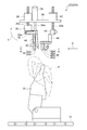
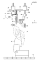
チェーンコンベア12には、「コーン」と呼ばれる複数の固定冶具20が等間隔に装着される。図示した実施形態では、固定冶具20の上半分は円錐形を有し、チェーンコンベア12に対して垂直方向に立設されるが、搬送途中で必要に応じ傾斜可能に構成される。
チェーンコンベア12は固定冶具20の搬送経路を形成し、固定冶具20はこの搬送経路に沿って搬送される。 A shoulder blade musing device according to some embodiments of the present invention will be described with reference to FIGS. The scapula
A plurality of fixing
The
例示的な実施形態では、チェーンコンベア12の基準点からの固定冶具20の搬送距離を検出するための搬送距離検出部を備えている。
上記搬送距離検出部は、例えば、モータ16に設けられモータ16の累計回転数を検出するエンコーダ18で構成される。エンコーダ18でモータ16の累計回転数を計測することで、例えばモータ位置を基準点としてモータ位置からの各固定冶具20の移動量(搬送距離)を検出できる。 Poultry animals whose legs were separated in the pre-treatment process and hollowed out to become only the upper body, for example, chicken carcass (hereinafter referred to as "work") w is a worker at the beginning of the
In the exemplary embodiment, the conveyance distance detection unit for detecting the conveyance distance of the fixing
The conveyance distance detection unit is constituted by, for example, an
筋入れ部22は、チェーンコンベア12の上方に上下動可能に設けられた第1の剥離部材24と、第1の剥離部材24を上下方向へ移動させるための駆動装置(第1の駆動装置)とを備えている。
上記駆動装置は、例えば、図2に示すように、支持台28に支持されたサーボモータ26で構成される。サーボモータ26は、支持台36を上下に貫通するネジ軸26aを回転させる。ネジ軸26aには、ネジ軸26aの回転によってネジ軸26a上を摺動する可動ブロック30が設けられる。ブラケット32は、一端が軸32aを介して可動ブロック30に回動可能に装着され、他端から第1の剥離部材24が垂下される。 In some embodiments, as shown in FIGS. 2, 8 and 10, creases 22 (22 A, 22 B, 22 C) are provided above the
The grooved
The drive device is constituted of, for example, a
上記弾性支持部は、図2及び図8に示す筋入れ部22(22A、22B)では、支持台28に固定されたエアシリンダ34で構成され、エアシリンダ34のピストンロッド34aは下方に向けて支持台28を貫通し、第1の剥離部材24が固定された側のブラケット32の端部に結合されている。
上記弾性支持部は、図10に示す筋入れ部22(22C)では、支持台28とブラケット32との間に介装されたコイルバネ36で構成されている。
また、筋入れ部22は、固定冶具20に固定されたワークwが第1の剥離部材下方の肉分離位置に来たタイミングに合わせて、サーボモータ26を作動させて第1の剥離部材24を下降させワークwの肩甲骨表面に沿わせ第1の剥離部材24を移動させるように構成されている。例示的な実施形態では、第1の剥離部材24にかかる動作を可能にする同期装置を備える。
かかる構成により、上記肉分離位置に来たワークwの肩甲骨に付着した肉部を分離する。 In the exemplary configuration, the creased
The elastic support portion is composed of the
The elastic support portion is constituted by a
In addition, the creasing
According to this configuration, the meat portion attached to the scapula of the work w that has come to the above-described meat separation position is separated.
かかる形状のスクレーパ部材24a及び24bが下降した時、ワークwの肩甲骨の表面に接触し、肩甲骨の表面に付着した肉部を肩甲骨から歩留まり良く分離できる。 In the exemplary embodiment, the first peeling
When the
また、固定冶具20に固定されたワークwが第2の剥離部材下方の肉分離位置に来たタイミングに合わせて、サーボモータ42を作動させて第2の剥離部材40を下降させる同期装置を備える。
かかる構成により、上記肉分離位置に来たワークwに対して第2の剥離部材40を下降させ、鎖骨に付着した肉部を分離する。
上記同期装置は、例えば、図2に示すように、支持台28に支持されたサーボモータ42で構成される。 In the exemplary embodiment, the
In addition, a synchronization device is provided that operates the
With this configuration, the
The synchronization device is constituted by, for example, a
図2及び図3に図示した実施形態では、第2の剥離部材40は、スクレーパ部材40a、40b、40c及び40dで構成されている。搬送方向上流側に配置された一対のスクレーパ部材40a及び40bは、中心線Cに対し平行でかつ対称に配置され、搬送方向下流側に配置された一対のスクレーパ部材40c及び40dは、中心線Cに対し直角でかつ対称に配置されている。
上記構成のスクレーパ部材40a~40dによって、ワークwの鎖骨の両外側にスクレーパ部材40a~40dが入り込み、鎖骨に付着した肉部を分離できる。 In the illustrated embodiment, as shown in FIG. 2, the
In the embodiment illustrated in FIGS. 2 and 3, the second stripping
The
上記同期装置は、エンコーダ18で検出した検出値から、制御装置52によって第1の剥離部材24の下降タイミングを決定し、サーボモータ26を作動させ、第1の剥離部材24を下降させる。筋入れ部22(22A、22B)では、第1の剥離部材24と同時にエアシリンダ34を作動させ、ブラケット32を水平に保ったまま下降させる。これによって、第1の剥離部材24を構成するスクレーパ部材24a及び24bを垂直方向のまま下降できる。
また、上記同期装置は、エンコーダ18で検出した検出値から、制御装置52で第2の剥離部材40の下降タイミングを決定し、サーボモータ42を作動させて第2の剥離部材40を下降させる。 In the exemplary embodiment, as shown in FIG. 4, the synchronization device is an encoder for detecting the movement amount (conveying distance) of each fixing
The synchronization device determines the lowering timing of the first peeling
Further, the synchronization device determines the lowering timing of the
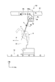
外形計測部60は、搬送経路上方に設けられた接触子66と、接触子66がワークwの肩部表面に倣うように接触子66を弾性的に支持するための弾性支持部と、接触子66がワークwに接触したときの接触子66の位置情報が入力される外形演算部76とを備えている。外形演算部76は制御装置74に内蔵され、入力された接触子66の位置情報からワークwの外形形状を演算する。
制御装置74は、エンコーダ18で検出した検出値及び外形計測部60で求めたワークwの外形形状から第2の剥離部材24又は第2の剥離部材40の下降タイミングを決定する。 In the exemplary embodiment, as shown in FIGS. 5 and 6, an outer
The outer
The control device 74 determines the lowering timing of the
計測ブロック62には、上記弾性支持部としてエアシリンダ68が設けられ、エアシリンダ68のピストンロッド68aはアーム70を介して支軸64に接続されている。接触バー66の他端は、固定冶具20の搬送経路上を接近してくるワークwの肩部sに接触するように位置決めされている。接触バー66がワークwの肩部sに接触した時、エアシリンダ68の付勢力(弾性力)が接触バー66に付加され、これによって、接触バー66は肩部sの表面を倣うことができる。支軸64には支軸64の回転角度を計測する角度計測センサ72が設けられている。 In the illustrated embodiment, as shown in FIG. 5, the
The
こうして求めたワークwの外形形状を表示する表示部(不図示)が筋入れ部22に設けられる。該表示部はワークwの外形形状を表示するディスプレイ78を有している。 FIG. 6 shows a control system of the present embodiment. In FIG. 6, the control device 74 controls the
A display unit (not shown) for displaying the outer shape of the workpiece w obtained in this manner is provided in the
エンコーダ18、外形計測部60及び制御装置74で、第1の剥離部材24及び第2の剥離部材40の下降タイミングを決定する同期装置を構成している。
この実施形態では、エンコーダ18から制御装置74に入力される各固定冶具20の位置情報に加えて、ディスプレイ78に表示される外形形状プロファイルに基づいて、第1の剥離部材24及び第2の剥離部材40の下降タイミングを決定する。 The display of the display 78 is shown in FIG. In FIG. 7, the line A is the outer shape of the shoulder s of the workpiece w measured by the
The
In this embodiment, in addition to the positional information of each fixing
この実施形態では、サーボモータ86及び88を稼動させ、ネジ軸86a及び88aを回転させることで、第1の支持ブロック80と第2の支持ブロック82との搬送方向の間隔を可変とすることができる。 The grooved portion 22 (22B) shown in FIG. 8 supports the
In this embodiment, the distance between the
第1の支持ブロック80の底壁を構成する支持板80aには、図2に示す筋入れ部22(22A)と同様に、サーボモータ26及びエアシリンダ34が固定されると共に、ネジ軸26a及びピストンロッド34aには、可動ブロック30、ブラケット32及び第1の剥離部材24が装着されている。
また、第2の支持ブロック82の底壁を構成する支持板82aには、サーボモータ42が固定されると共に、ネジ軸42aには、図2に示す筋入れ部22(22A)と同様に、可動ブロック44及びL型ブロック46を介して第2の剥離部材40が装着されている。 In the exemplary configuration illustrated in FIG. 8, the moving
The
Further, the
例示的な実施形態では、上記弾性支持部は、図10に示す筋入れ部22(22C)のように、支持台28とブラケット32との間に介設されたコイルバネ36で構成される。 In the exemplary embodiment, the elastic support portion that elastically supports the first peeling
In the exemplary embodiment, the elastic support portion is constituted by a
また、第1の剥離部材24は上記弾性支持部によって弾性的に支持されるため、ワークwから第1の剥離部材24に一定以上の反力が加わると、第1の剥離部材24は搬送方向下流側(矢印b方向)へ逃げることができる。そのため、第1の剥離部材24によってワークwに過剰の力が付加されず、ワークwの骨部などの破壊を防止できると共に、第1の剥離部材24をワークwの表面に沿って倣わせることができ、これによって、分離後の肉部の歩留まりを向上できる。
また、筋入れ部22によって肩筋入れ工程を自動化できるため、処理効率を向上できる。 According to some embodiments, the first peeling
In addition, since the first peeling
In addition, since the shoulder putting process can be automated by the putting-in
また、第1の剥離部材24の搬送方向上流側に第2の剥離部材40を備えているので、肩甲骨肉分離工程の前で鎖骨に付着した肉部を鎖骨から分離でき、これによって、肩甲骨の肉分離が容易になる。
また、エンコーダ18でチェーンコンベア12の基準点からの各固定冶具20の搬送距離を検出し、その位置情報に基づいて、第1の剥離部材24及び第2の剥離部材40の下降タイミングを決定するので、肩甲骨及び鎖骨の肉分離を確実に行うことができる。 Further, the first peeling
Further, since the
Further, the transport distance of each fixing
さらに、接触子66はワークwの肩部表面に倣うように弾性的に支持されるので、ワークwの肩部表面に確実に倣わせることができる。 Further, according to the exemplary embodiment, as shown in FIG. 5 and FIG. 6, in addition to the position information of the
Furthermore, since the
また、図8及び図9に示す筋入れ部22(22C)では、第2の剥離部材24及び第2の剥離部材40は、夫々別個の第1の支持台80及び第2の支持台82に支持され、第1の支持台80と第2の支持台82とは、移動部84によって搬送方向の間隔を調整可能であるので、固定冶具20の搬送速度や搬送方向の間隔、さらには、各ワークの大きさ及び外形形状に合わせて筋入れしやすい最適な間隔に調整できる。 Further, in the grooved portion 22 (22B) shown in FIG. 2, the first peeling
Further, in the creased portion 22 (22C) shown in FIG. 8 and FIG. 9, the
また、図10に示す筋入れ部22(22C)では、第2の剥離部材24はコイルバネ36で弾性的に支持されるので、弾性支持部を簡易かつ低コスト化できる。 Further, in the creased portion 22 (22A) shown in FIG. 2, since the
Further, in the creased portion 22 (22C) shown in FIG. 10, since the
12 チェーンコンベア
14 駆動スプロケット
16 モータ
18 エンコーダ(搬送距離検出部)
20 固定冶具
22(22A、22B、22C) 筋入れ部
24 第1の剥離部材
24a、24b スクレーパ部材
26、42、86,88 サーボモータ
26a、42a、86a、88a ネジ軸
28 支持台
30、44 可動ブロック
32 ブラケット
34 エアシリンダ(弾性支持部)
34a ピストンロッド
36 コイルバネ(弾性支持部)
40 第2の剥離部材
40a、40b、40c、40d スクレーパ部材
46 L型ブロック
48 補強棒
50 鎬
52,74 制御装置
60 外形計測部
61 支持フレーム
62 計測ブロック
64 支軸
66 接触バー(接触子)
70 アーム
72 角度計測センサ
76 外形演算部
78 ディスプレイ
80 第1の支持ブロック
80a 支持板
82 第2の支持ブロック
82a 支持板
84 移動部
90、92 軸受
C 中心線
s 肩部
w ワーク(食鳥屠体) 10 scapula
40
70
Claims (9)
- 食鳥屠体の肩甲骨と該肩甲骨に付着した肉部とを分離する肩甲骨筋入れ装置であって、
脚部が分離され中抜きされた食鳥屠体を載置固定するための固定冶具と、
前記固定冶具の搬送経路を形成し、前記固定冶具を該搬送経路に沿って搬送するコンベアと、
前記搬送経路の上方に上下動可能に設けられた第1の剥離部材と、
前記第1の剥離部材を上下方向へ移動させるための第1の駆動装置とを備え、
前記固定冶具に固定された前記食鳥屠体が前記第1の剥離部材下方の肉分離位置に来たタイミングに合わせて、前記第1の駆動装置を作動させて前記第1の剥離部材を下降させ前記食鳥屠体の肩甲骨表面に沿わせ前記第1の剥離部材を移動させ、
前記肩甲骨から該肩甲骨に付着した肉部を分離することを特徴とする肩甲骨筋入れ装置。 A scapula musk insertion device for separating a scapula of a poultry carcass and a meat attached to the scapula, comprising:
A fixing jig for mounting and fixing the cut-out food bird carcass separated in the legs;
A conveyor which forms a transport path of the fixing jig and transports the fixing jig along the transport path;
A first peeling member provided vertically movable above the transfer path;
A first drive device for moving the first peeling member in the vertical direction;
The first driving device is operated to lower the first peeling member in accordance with the timing when the food bird carcass fixed to the fixing jig comes to the meat separating position below the first peeling member. Moving the first exfoliation member along the scapula surface of the food bird carcass;
A scapula muscle inserting device characterized by separating the meat attached to the scapula from the scapula. - 前記第1の剥離部材は、前記搬送経路に沿い前記固定冶具の中心を通る中心線を挟んで該中心線の両側に配置された一対のスクレーパ部材で構成され、
前記一対のスクレーパ部材は前記食鳥屠体の搬送方向下流側に向けてスクレーパ部材間の間隔が徐々に狭まる向きに配置されていることを特徴とする請求項1に記載の肩甲骨筋入れ装置。 The first peeling member includes a pair of scraper members disposed on both sides of a center line passing the center of the fixing jig along the transport path.
The shoulder blade musing device according to claim 1, wherein the pair of scraper members are disposed in a direction in which the distance between the scraper members is gradually narrowed toward the downstream side of the feeding direction of the chicken carcass. . - 前記第1の剥離部材の前記固定冶具の搬送方向上流側で前記搬送経路の上方に設けられた第2の剥離部材と、
前記第2の剥離部材を上下方向へ移動させるための第2の駆動装置と、を備え、
前記固定冶具に固定された前記食鳥屠体が前記第2の剥離部材下方の肉分離位置に来たタイミングに合わせて、前記第2の駆動装置を作動させて前記第2の剥離部材を下降させ前記食鳥屠体の鎖骨に付着した肉部を分離することを特徴とする請求項1又は2に記載の肩甲骨筋入れ装置。 A second peeling member provided above the conveyance path on the conveyance direction upstream side of the fixing jig of the first peeling member;
A second driving device for moving the second peeling member in the vertical direction,
The second driving device is operated to lower the second peeling member in accordance with the timing when the food bird carcass fixed to the fixing jig comes to the meat separating position below the second peeling member. The scapula muscle inserting device according to claim 1 or 2, characterized in that the meat portion attached to the clavicle of the feedbird carcass is separated. - 前記コンベアの基準点からの前記固定冶具の搬送距離を検出するための搬送距離検出部と、
前記搬送距離検出部で検出した検出値から前記第1の剥離部材及び前記第2の剥離部材の下降タイミングを決定し、前記第1の駆動装置及び前記第2の駆動装置を作動させて前記第1の剥離部材及び前記第2の剥離部材を下降させるための制御装置と、で構成されている同期装置を備えることを特徴とする請求項1乃至3の何れか1項に記載の肩甲骨筋入れ装置。 A transport distance detection unit for detecting a transport distance of the fixing jig from a reference point of the conveyor;
The descent timing of the first peeling member and the second peeling member is determined from the detection value detected by the conveyance distance detection unit, and the first driving device and the second driving device are operated to operate the first driving device and the second driving device. The scapula muscle according to any one of claims 1 to 3, further comprising: a synchronization device configured of: the first peeling member and a control device for lowering the second peeling member. Insertion device. - 前記第2の剥離部材より前記固定冶具の搬送方向上流側の前記搬送経路に設けられた接触子と、
前記接触子が前記食鳥屠体の肩部表面に倣うように前記接触子を弾性的に支持するための弾性支持部と、
前記接触子が前記食鳥屠体に接触したときの前記接触子の位置情報が入力され、前記位置情報から前記食鳥屠体の外形形状を演算するための外形演算部と、を有する外形計測部をさらに備え、
前記制御装置は、前記搬送距離検出部で検出した検出値及び前記外形計測部で求めた前記食鳥屠体の外形形状から前記第1の剥離部材及び前記第2の剥離部材の下降タイミングを決定するものであることを特徴とする請求項4に記載の肩甲骨筋入れ装置。 A contact provided on the transport path on the upstream side in the transport direction of the fixing jig from the second peeling member;
An elastic support for resiliently supporting the contacts such that the contacts follow the shoulder surface of the carcass of the food bird;
Measurement of position of the contactor when the contactor comes in contact with the feedbird carcass, and an outer shape measurement unit for calculating an outer shape of the feedbird carcass from the position information Further equipped with
The control device determines the descent timing of the first peeling member and the second peeling member from the detection value detected by the conveyance distance detection unit and the outer shape of the food bird carcass obtained by the outer shape measurement unit. The shoulder blade musing device according to claim 4, characterized in that: - 前記第1の剥離部材及び前記第2の剥離部材は、単一の支持台に上下動可能に支持されていることを特徴とする請求項3乃至5の何れか1項に記載の肩甲骨筋入れ装置。 The scapula muscle according to any one of claims 3 to 5, wherein the first peeling member and the second peeling member are vertically movably supported by a single support base. Insertion device.
- 前記第1の剥離部材を上下動可能に支持するための第1の支持台と、
前記第2の剥離部材を上下動可能に支持するための第2の支持台と、
前記第1の支持台と前記第2の支持台との間隔を前記固定冶具の搬送方向で可変とするための移動部と、をさらに備えていることを特徴とする請求項3乃至5の何れか1項に記載の肩甲骨筋入れ装置。 A first support for supporting the first peeling member so as to move up and down;
A second support for supporting the second peeling member so as to move up and down;
The moving part for making the space | interval of a said 1st support stand and a said 2nd support stand variable in the conveyance direction of the said fixing jig is further provided, Any one of the Claims 3 thru | or 5 characterized by the above-mentioned. The scapula muscular insertion device according to any one of the preceding claims. - 前記弾性支持部は、前記第1の剥離部材と前記第1の剥離部材を支持する支持部材との間に介設されたエアシリンダで構成されていることを特徴とする請求項1乃至7の何れか1項に記載の肩甲骨筋入れ装置。 The said elastic support part is comprised by the air cylinder interposed between the said 1st peeling member and the supporting member which supports the said 1st peeling member, The 1st to 7th characterized by the above-mentioned. The scapula muscle inserting device according to any one of the above.
- 前記弾性支持部は、前記第1の剥離部材と前記第1の剥離部材を支持する支持部材との間に介設されたバネ部材で構成されていることを特徴とする請求項1乃至7の何れか1項に記載の肩甲骨筋入れ装置。 The elastic support portion is constituted by a spring member interposed between the first peeling member and a supporting member for supporting the first peeling member. The scapula muscle inserting device according to any one of the above.
Priority Applications (13)
| Application Number | Priority Date | Filing Date | Title |
|---|---|---|---|
| BR112016029770-9A BR112016029770B1 (en) | 2014-06-30 | 2015-06-25 | APPARATUS TO PERFORM SKIPLE INCISION |
| ES15814418.8T ES2689478T3 (en) | 2014-06-30 | 2015-06-25 | Scapula incision apparatus |
| DK15814418.8T DK3162213T3 (en) | 2014-06-30 | 2015-06-25 | SHOULDER CUTTING DEVICE |
| JP2016531318A JP6216056B2 (en) | 2014-06-30 | 2015-06-25 | Shoulder blade insertion device |
| US15/322,728 US9706782B2 (en) | 2014-06-30 | 2015-06-25 | Shoulder-blade incision-making apparatus |
| MYPI2016704825A MY188560A (en) | 2014-06-30 | 2015-06-25 | Shoulder-blade incision-making apparatus |
| KR1020177002392A KR101852733B1 (en) | 2014-06-30 | 2015-06-25 | Scapula incision device |
| MX2016016819A MX2016016819A (en) | 2014-06-30 | 2015-06-25 | Scapula incision device. |
| CA2953893A CA2953893C (en) | 2014-06-30 | 2015-06-25 | Shoulder-blade incision-making apparatus |
| AU2015285485A AU2015285485B2 (en) | 2014-06-30 | 2015-06-25 | Scapula incision device |
| PL15814418T PL3162213T3 (en) | 2014-06-30 | 2015-06-25 | Scapula incision device |
| EP15814418.8A EP3162213B1 (en) | 2014-06-30 | 2015-06-25 | Scapula incision device |
| PH12016502486A PH12016502486B1 (en) | 2014-06-30 | 2016-12-13 | Shoulder-blade incision-making apparatus |
Applications Claiming Priority (6)
| Application Number | Priority Date | Filing Date | Title |
|---|---|---|---|
| JP2014-134088 | 2014-06-30 | ||
| JP2014-134086 | 2014-06-30 | ||
| JP2014134086 | 2014-06-30 | ||
| JP2014134087 | 2014-06-30 | ||
| JP2014-134087 | 2014-06-30 | ||
| JP2014134088 | 2014-06-30 |
Publications (1)
| Publication Number | Publication Date |
|---|---|
| WO2016002629A1 true WO2016002629A1 (en) | 2016-01-07 |
Family
ID=55019169
Family Applications (3)
| Application Number | Title | Priority Date | Filing Date |
|---|---|---|---|
| PCT/JP2015/068359 WO2016002629A1 (en) | 2014-06-30 | 2015-06-25 | Scapula incision device |
| PCT/JP2015/068360 WO2016002630A1 (en) | 2014-06-30 | 2015-06-25 | Chicken carcass contour measurement device, contour measurement method, and chicken carcass deboning device |
| PCT/JP2015/068358 WO2016002628A1 (en) | 2014-06-30 | 2015-06-25 | Chicken-tenderloin extraction device |
Family Applications After (2)
| Application Number | Title | Priority Date | Filing Date |
|---|---|---|---|
| PCT/JP2015/068360 WO2016002630A1 (en) | 2014-06-30 | 2015-06-25 | Chicken carcass contour measurement device, contour measurement method, and chicken carcass deboning device |
| PCT/JP2015/068358 WO2016002628A1 (en) | 2014-06-30 | 2015-06-25 | Chicken-tenderloin extraction device |
Country Status (15)
| Country | Link |
|---|---|
| US (3) | US9700060B2 (en) |
| EP (3) | EP3162213B1 (en) |
| JP (3) | JP6262344B2 (en) |
| KR (3) | KR101896854B1 (en) |
| AU (3) | AU2015285484B2 (en) |
| CA (3) | CA2954039C (en) |
| CL (3) | CL2016003265A1 (en) |
| DK (1) | DK3162213T3 (en) |
| ES (1) | ES2689478T3 (en) |
| HU (1) | HUE039817T2 (en) |
| MX (3) | MX2016016819A (en) |
| MY (3) | MY188560A (en) |
| PH (3) | PH12016502486B1 (en) |
| PL (1) | PL3162213T3 (en) |
| WO (3) | WO2016002629A1 (en) |
Cited By (1)
| Publication number | Priority date | Publication date | Assignee | Title |
|---|---|---|---|---|
| WO2024029343A1 (en) * | 2022-08-03 | 2024-02-08 | 株式会社前川製作所 | Poultry processing device |
Families Citing this family (21)
| Publication number | Priority date | Publication date | Assignee | Title |
|---|---|---|---|---|
| NL2016700B1 (en) * | 2016-04-29 | 2017-11-16 | Marel Stork Poultry Proc Bv | System and method for measuring a shoulder joint position of a carcass part of slaughtered poultry. |
| JP6735055B2 (en) * | 2016-09-28 | 2020-08-05 | プライフーズ株式会社 | Poultry carcass chicken fillet mechanism |
| JP6735054B2 (en) * | 2016-09-28 | 2020-08-05 | プライフーズ株式会社 | Poultry carcass chicken fillet device |
| NL2019364B1 (en) * | 2017-07-28 | 2019-02-19 | Meyn Food Processing Tech Bv | Scapula harvester for operating on a poultry carcass |
| HUE063485T2 (en) * | 2017-10-06 | 2024-01-28 | Maekawa Seisakusho Kk | Clamp device for leg meat on the bone, loading device for leg meat on the bone, and method for clamping leg meat on the bone |
| JP6946169B2 (en) * | 2017-12-25 | 2021-10-06 | 株式会社前川製作所 | Cartilage cutting device and cartilage cutting method for bone-in meat |
| CN108184972B (en) * | 2018-03-01 | 2020-05-12 | 岳西神农氏农业科技有限公司 | Chicken claw shank joint cutting device |
| CN108262777A (en) * | 2018-03-02 | 2018-07-10 | 刘书雄 | A kind of Chinese medicine cuts medicine device |
| CN109329360B (en) * | 2018-09-26 | 2021-06-25 | 北海智联投资有限公司 | Auxiliary device for opening roasted chicken |
| CN109349327B (en) * | 2018-09-27 | 2021-07-02 | 北海智联投资有限公司 | Device for automatically opening chicken belly skin and opening chicken belly skin |
| US11202452B2 (en) | 2019-04-08 | 2021-12-21 | Provisor Technologies, Inc. | Apparatus and method for cutting meat products into blocks of meat |
| DE102019119665B3 (en) * | 2019-07-19 | 2020-06-25 | Nordischer Maschinenbau Rud. Baader Gmbh + Co. Kg | Device for measuring the shoulder joint position of continuously transported poultry bodies, arrangement for filleting poultry bodies and corresponding methods |
| KR102121205B1 (en) * | 2019-10-22 | 2020-06-10 | 김만섭 | Wishbone Separator to separate wishbone from poultry |
| KR102121204B1 (en) * | 2019-10-22 | 2020-06-10 | 김만섭 | Wishbone Separator with Penetration to Separate Wishbone from Poultry |
| JP2021177710A (en) * | 2020-05-12 | 2021-11-18 | 株式会社前川製作所 | Workpiece measuring device and streaking system |
| EP4149269A1 (en) | 2020-05-15 | 2023-03-22 | Nordischer Maschinenbau Rud. Baader GmbH + Co. KG | Transport device for transporting eviscerated poultry carcasses or parts thereof, and device and method for attaching and processing the poultry carcasses or parts thereof |
| CN111887285A (en) * | 2020-07-28 | 2020-11-06 | 从海彬 | Chicken leg boning equipment |
| CN112088924B (en) * | 2020-09-11 | 2022-02-25 | 衢州学院 | Chicken claw surface automatic cutting device |
| US20220167635A1 (en) * | 2020-11-27 | 2022-06-02 | Ace, Llc | Automated Chicken Deboner System and Method |
| US11751578B2 (en) | 2021-12-31 | 2023-09-12 | Ocean Research Center Of Zhoushan, Zhejiang University | Intelligent methods and devices for cutting squid white slices |
| WO2023237912A1 (en) * | 2022-06-08 | 2023-12-14 | Tmec Indústria E Comércio De Equipamentos Industriais Ltda-Me | Automated system and method for the hanging of live birds to slaughter |
Citations (2)
| Publication number | Priority date | Publication date | Assignee | Title |
|---|---|---|---|---|
| JPH11266780A (en) * | 1998-01-21 | 1999-10-05 | Mayekawa Mfg Co Ltd | Automatic bone removal treatment of upper half of chicken body and device therefor |
| JP2011125317A (en) * | 2009-12-21 | 2011-06-30 | Prifoods Co Ltd | Apparatus for making cut in poultry carcass |
Family Cites Families (33)
| Publication number | Priority date | Publication date | Assignee | Title |
|---|---|---|---|---|
| DE3736401C1 (en) * | 1987-10-28 | 1989-03-02 | Nordischer Maschinenbau | Device for skinning poultry carcasses |
| ES2035375T3 (en) * | 1989-01-28 | 1993-04-16 | Nordischer Maschinenbau Rud. Baader Gmbh + Co Kg | PROCEDURE FOR MECHANICAL OBTAINING OF MEAT FROM BIRDS OF BIRDS AND DEVICE FOR CONDUCTING THE PROCEDURE. |
| DE3939340C1 (en) * | 1989-11-29 | 1991-06-06 | Nordischer Maschinenbau Rud. Baader Gmbh + Co Kg, 2400 Luebeck, De | |
| NL9200037A (en) | 1992-01-10 | 1993-08-02 | Stork Pmt | METHOD AND APPARATUS FOR FILLING THE HULL OF A GENDER BIRD |
| NL9200733A (en) * | 1992-04-22 | 1993-11-16 | Passchier Bob | APPARATUS AND METHODS FOR REMOVING AND / OR REMOVING MEAT AND SIMILAR FROM ANIMAL HEADS. |
| NL9201426A (en) * | 1992-04-23 | 1993-11-16 | Stork Protecon Bv | METHOD AND APPARATUS FOR PREPARING A PIG HEAD FOR MACHINE BONUS. |
| US5314374A (en) | 1993-06-14 | 1994-05-24 | Jay Koch | Apparatus for removing tenders from a poultry carcass |
| US5368520A (en) * | 1994-01-18 | 1994-11-29 | Koch; Jay | Apparatus and method for separating wings and attached breasts from poultry carcasses |
| US5573454A (en) * | 1994-06-17 | 1996-11-12 | Devro-Teepak, Inc. | Method and apparatus for aligning labels on shirred food casings |
| NL9401198A (en) * | 1994-07-21 | 1996-03-01 | Stork Pmt | Method and device for filleting the hull of slaughtered poultry. |
| NL1000935C2 (en) * | 1995-08-04 | 1997-02-06 | Stork Pmt | Apparatus and method for processing a slaughtered animal. |
| US5954574A (en) | 1997-08-12 | 1999-09-21 | Verrijp; Bastiaan | Wing remover |
| US6322437B1 (en) * | 1997-10-17 | 2001-11-27 | Nordischer Maschinenbau Rud. Baader Gmbh + Co Kg | Method for stripping the muscle meat from fish and device for carrying out this method |
| US6042469A (en) * | 1998-04-06 | 2000-03-28 | Wagner; Rory | Air clamp |
| DE19848498A1 (en) | 1998-10-21 | 2000-05-04 | Nordischer Maschinenbau | Filleting device |
| JP4222878B2 (en) | 2002-05-31 | 2009-02-12 | 株式会社栗本鐵工所 | High-temperature corrosion-resistant material for air heating pipe of gasification melting furnace |
| WO2004052106A1 (en) | 2002-12-11 | 2004-06-24 | Mayekawa Mfg.Co.,Ltd. | Automatic bone removal processing equipment for upper half of chicken meat slaughtered body |
| GB2421676B (en) * | 2004-12-30 | 2010-03-24 | Fmc Technologies | Portioning apparatus and method |
| WO2006077673A1 (en) * | 2005-01-20 | 2006-07-27 | Mayekawa Mfg. Co., Ltd | Device for removing fin from fish body |
| NL1029227C2 (en) * | 2005-06-10 | 2006-12-12 | Meyn Food Proc Technology Bv | Method and device for harvesting an inner fillet of poultry. |
| CA2552168A1 (en) * | 2005-07-18 | 2007-01-18 | Groupe Grb Inc. | Artificial vision inspection method and system |
| DE102005047752B3 (en) * | 2005-09-28 | 2006-10-05 | Nordischer Maschinenbau Rud. Baader Gmbh + Co Kg | Trimming machine for fish fillets has conveyor which continuously feeds fillets to trimming head and camera which detects position of each fillet and controls head so that it automatically trims its surface |
| BRPI0622404B1 (en) | 2005-12-09 | 2015-11-24 | Stork Pmt | device and method for processing a part of the carcass of the slaughtered bird |
| DE102006021526B3 (en) * | 2006-05-06 | 2007-09-20 | Nordischer Maschinenbau Rud. Baader Gmbh + Co. Kg | Tool for gutting of salmon species opened in abdominal cavity, formed as suction element for entrails and as a combination tool, where the suction element is assigned an element for clamping and/or squeezing the entrails to be removed |
| DE102006040454B3 (en) * | 2006-08-25 | 2007-12-06 | Nordischer Maschinenbau Rud. Baader Gmbh + Co. Kg | Processing good e.g. poultry body, holding device, has supporting unit to support parts of goods such that measuring points are freely accessible in goods, where parts of goods protrude over device in transport direction of holding device |
| DE102007050857A1 (en) * | 2007-10-24 | 2009-04-30 | Weber Maschinenbau Gmbh Breidenbach | Fat pad measuring device |
| JP5455710B2 (en) * | 2010-02-27 | 2014-03-26 | プライフーズ株式会社 | A poultry carcass shoulder joint position detector |
| NL2004662C2 (en) * | 2010-05-04 | 2011-11-08 | Meyn Food Proc Technology Bv | A method for filleting poultry or poultry parts and a filleting system for such poultry or poultry parts. |
| DE102011010110A1 (en) * | 2011-02-02 | 2012-08-02 | Weber Maschinenbau Gmbh Breidenbach | Apparatus and method for removing a surface layer of food products |
| JP5818518B2 (en) | 2011-06-06 | 2015-11-18 | 株式会社前川製作所 | Method and apparatus for separating winged breast |
| JP5623352B2 (en) | 2011-07-13 | 2014-11-12 | 株式会社前川製作所 | Method and apparatus for separating the thoracic skeleton |
| WO2013136995A1 (en) * | 2012-03-13 | 2013-09-19 | 株式会社前川製作所 | Scapula removal device and method for meat on the bone, and deboning system for meat on the bone equipped with said device |
| WO2013136993A1 (en) * | 2012-03-13 | 2013-09-19 | 株式会社前川製作所 | Conveyance device and method for meat on the bone, and deboning system for meat on the bone provided with said device |
-
2015
- 2015-06-25 EP EP15814418.8A patent/EP3162213B1/en active Active
- 2015-06-25 JP JP2016531317A patent/JP6262344B2/en active Active
- 2015-06-25 DK DK15814418.8T patent/DK3162213T3/en active
- 2015-06-25 PL PL15814418T patent/PL3162213T3/en unknown
- 2015-06-25 WO PCT/JP2015/068359 patent/WO2016002629A1/en active Application Filing
- 2015-06-25 EP EP15815135.7A patent/EP3162215A4/en not_active Withdrawn
- 2015-06-25 MY MYPI2016704825A patent/MY188560A/en unknown
- 2015-06-25 JP JP2016531319A patent/JP6216057B2/en active Active
- 2015-06-25 HU HUE15814418A patent/HUE039817T2/en unknown
- 2015-06-25 AU AU2015285484A patent/AU2015285484B2/en not_active Ceased
- 2015-06-25 CA CA2954039A patent/CA2954039C/en active Active
- 2015-06-25 US US15/323,094 patent/US9700060B2/en active Active
- 2015-06-25 ES ES15814418.8T patent/ES2689478T3/en active Active
- 2015-06-25 KR KR1020177002390A patent/KR101896854B1/en active IP Right Grant
- 2015-06-25 JP JP2016531318A patent/JP6216056B2/en active Active
- 2015-06-25 MY MYPI2016704826A patent/MY189012A/en unknown
- 2015-06-25 MX MX2016016819A patent/MX2016016819A/en active IP Right Grant
- 2015-06-25 WO PCT/JP2015/068360 patent/WO2016002630A1/en active Application Filing
- 2015-06-25 KR KR1020177002392A patent/KR101852733B1/en active IP Right Grant
- 2015-06-25 EP EP15814808.0A patent/EP3162214A4/en not_active Withdrawn
- 2015-06-25 MX MX2016016570A patent/MX2016016570A/en unknown
- 2015-06-25 AU AU2015285486A patent/AU2015285486B2/en not_active Ceased
- 2015-06-25 MY MYPI2016704841A patent/MY175780A/en unknown
- 2015-06-25 US US15/322,730 patent/US9687007B2/en active Active
- 2015-06-25 WO PCT/JP2015/068358 patent/WO2016002628A1/en active Application Filing
- 2015-06-25 AU AU2015285485A patent/AU2015285485B2/en not_active Ceased
- 2015-06-25 US US15/322,728 patent/US9706782B2/en active Active
- 2015-06-25 CA CA2953893A patent/CA2953893C/en active Active
- 2015-06-25 MX MX2016016681A patent/MX2016016681A/en unknown
- 2015-06-25 KR KR1020177002393A patent/KR101852734B1/en active IP Right Grant
- 2015-06-25 CA CA2953896A patent/CA2953896C/en active Active
-
2016
- 2016-12-13 PH PH12016502486A patent/PH12016502486B1/en unknown
- 2016-12-13 PH PH12016502487A patent/PH12016502487A1/en unknown
- 2016-12-13 PH PH12016502488A patent/PH12016502488B1/en unknown
- 2016-12-20 CL CL2016003265A patent/CL2016003265A1/en unknown
- 2016-12-20 CL CL2016003267A patent/CL2016003267A1/en unknown
- 2016-12-20 CL CL2016003266A patent/CL2016003266A1/en unknown
Patent Citations (2)
| Publication number | Priority date | Publication date | Assignee | Title |
|---|---|---|---|---|
| JPH11266780A (en) * | 1998-01-21 | 1999-10-05 | Mayekawa Mfg Co Ltd | Automatic bone removal treatment of upper half of chicken body and device therefor |
| JP2011125317A (en) * | 2009-12-21 | 2011-06-30 | Prifoods Co Ltd | Apparatus for making cut in poultry carcass |
Non-Patent Citations (1)
| Title |
|---|
| See also references of EP3162213A4 * |
Cited By (1)
| Publication number | Priority date | Publication date | Assignee | Title |
|---|---|---|---|---|
| WO2024029343A1 (en) * | 2022-08-03 | 2024-02-08 | 株式会社前川製作所 | Poultry processing device |
Also Published As
Similar Documents
| Publication | Publication Date | Title |
|---|---|---|
| WO2016002629A1 (en) | Scapula incision device | |
| WO2016002631A1 (en) | Shoulder incision device and shoulder incision method | |
| JP6081019B2 (en) | Deboning apparatus and deboning method for meat with bone | |
| TWI680718B (en) | Device for measuring full length of bone with meat and method for measuring full length of bone with meat | |
| KR102331415B1 (en) | Boneless leg meat processing system and manufacturing method of separated meat | |
| JP7018454B2 (en) | Bone meat squeezing device and bone squeezing method | |
| BR112016029770B1 (en) | APPARATUS TO PERFORM SKIPLE INCISION |
Legal Events
| Date | Code | Title | Description |
|---|---|---|---|
| 121 | Ep: the epo has been informed by wipo that ep was designated in this application |
Ref document number: 15814418 Country of ref document: EP Kind code of ref document: A1 |
|
| ENP | Entry into the national phase |
Ref document number: 2016531318 Country of ref document: JP Kind code of ref document: A |
|
| WWE | Wipo information: entry into national phase |
Ref document number: 12016502486 Country of ref document: PH |
|
| WWE | Wipo information: entry into national phase |
Ref document number: MX/A/2016/016819 Country of ref document: MX |
|
| ENP | Entry into the national phase |
Ref document number: 2953893 Country of ref document: CA |
|
| WWE | Wipo information: entry into national phase |
Ref document number: 15322728 Country of ref document: US |
|
| NENP | Non-entry into the national phase |
Ref country code: DE |
|
| REG | Reference to national code |
Ref country code: BR Ref legal event code: B01A Ref document number: 112016029770 Country of ref document: BR |
|
| ENP | Entry into the national phase |
Ref document number: 2015285485 Country of ref document: AU Date of ref document: 20150625 Kind code of ref document: A |
|
| ENP | Entry into the national phase |
Ref document number: 20177002392 Country of ref document: KR Kind code of ref document: A |
|
| REEP | Request for entry into the european phase |
Ref document number: 2015814418 Country of ref document: EP |
|
| WWE | Wipo information: entry into national phase |
Ref document number: 2015814418 Country of ref document: EP |
|
| ENP | Entry into the national phase |
Ref document number: 112016029770 Country of ref document: BR Kind code of ref document: A2 Effective date: 20161219 |