WO2016002149A1 - 光通信方法およびシステム - Google Patents
光通信方法およびシステム Download PDFInfo
- Publication number
- WO2016002149A1 WO2016002149A1 PCT/JP2015/003018 JP2015003018W WO2016002149A1 WO 2016002149 A1 WO2016002149 A1 WO 2016002149A1 JP 2015003018 W JP2015003018 W JP 2015003018W WO 2016002149 A1 WO2016002149 A1 WO 2016002149A1
- Authority
- WO
- WIPO (PCT)
- Prior art keywords
- photon
- polarizer
- photon pair
- correlated
- shutter
- Prior art date
Links
Images
Classifications
-
- H—ELECTRICITY
- H04—ELECTRIC COMMUNICATION TECHNIQUE
- H04B—TRANSMISSION
- H04B10/00—Transmission systems employing electromagnetic waves other than radio-waves, e.g. infrared, visible or ultraviolet light, or employing corpuscular radiation, e.g. quantum communication
- H04B10/80—Optical aspects relating to the use of optical transmission for specific applications, not provided for in groups H04B10/03 - H04B10/70, e.g. optical power feeding or optical transmission through water
- H04B10/85—Protection from unauthorised access, e.g. eavesdrop protection
-
- H—ELECTRICITY
- H04—ELECTRIC COMMUNICATION TECHNIQUE
- H04B—TRANSMISSION
- H04B10/00—Transmission systems employing electromagnetic waves other than radio-waves, e.g. infrared, visible or ultraviolet light, or employing corpuscular radiation, e.g. quantum communication
- H04B10/50—Transmitters
- H04B10/516—Details of coding or modulation
- H04B10/532—Polarisation modulation
-
- H—ELECTRICITY
- H04—ELECTRIC COMMUNICATION TECHNIQUE
- H04B—TRANSMISSION
- H04B10/00—Transmission systems employing electromagnetic waves other than radio-waves, e.g. infrared, visible or ultraviolet light, or employing corpuscular radiation, e.g. quantum communication
- H04B10/70—Photonic quantum communication
-
- H—ELECTRICITY
- H04—ELECTRIC COMMUNICATION TECHNIQUE
- H04L—TRANSMISSION OF DIGITAL INFORMATION, e.g. TELEGRAPHIC COMMUNICATION
- H04L9/00—Cryptographic mechanisms or cryptographic arrangements for secret or secure communications; Network security protocols
- H04L9/08—Key distribution or management, e.g. generation, sharing or updating, of cryptographic keys or passwords
- H04L9/0816—Key establishment, i.e. cryptographic processes or cryptographic protocols whereby a shared secret becomes available to two or more parties, for subsequent use
- H04L9/0852—Quantum cryptography
Definitions
- the present invention relates to an optical communication method and system for transmitting and receiving information using photons.
- Non-Patent Documents 1 and 2 In recent years, research and experiments have been conducted on quantum cryptography communication using quantum mechanics principles (Non-Patent Documents 1 and 2).
- Conventional quantum cryptography communication has been studied on the premise that quantum photon superposed photons exist in the communication path. When superposed photons are observed by an eavesdropper, they transition from a superposed state to a unique state having definitive information. Due to such an effect, the eavesdropper cannot reproduce the original superposition state, and thus it is impossible to eavesdrop without affecting the transmitted / received information. For this reason, the original sender / receiver can detect the presence / absence of eavesdropping to ensure safety.
- Non-Patent Document 3 discloses an optical communication method as quantum cryptography communication.
- a transmitter performs phase modulation according to information to be transmitted to a photon, and transmits the photon to a receiver.
- the phase used by the sender cannot be known, so that a photon subjected to the same phase modulation cannot be retransmitted to the receiver.
- the mismatch (error) between the information transmitted by the sender and the information received by the receiver increases, so that the presence of an eavesdropper can be detected.
- the eavesdropper can measure the photons transmitted and received through the communication path.
- information for example, an encryption key
- it is possible to cope with eavesdropping by discarding information (for example, an encryption key) related to photons that may be illegally measured when the presence of an eavesdropper is detected. It cannot be denied that the photon gives some information to the eavesdropper. Therefore, it is more desirable to make it difficult for the eavesdropper to measure the photons themselves.
- the present invention has been made in view of the above-described problems, and an object thereof is to provide an optical communication method and system that is more difficult to wiretap than in the past.
- a first aspect of the present invention is an optical communication system, which is provided on one optical path of a correlated photon pair and a photon pair generating unit that generates a correlated photon pair, and is oriented based on transmitted information.
- a changeable polarizer, a shutter provided between the photon pair generation unit and the polarizer on the one optical path of the correlated photon pair, and capable of blocking the one of the correlated photon pairs; and the correlation And a photon detector provided on the other optical path of the photon pair.
- an optical communication method wherein the orientation of a polarizer is set based on transmitted information, and correlation is performed by a photon pair generation unit after the orientation of the polarizer is set. Generating a photon pair; blocking one of the correlated photon pairs by a shutter after the correlated photon pair is generated; and detecting a correlated photon pair by the detector after the correlated photon pair is generated. Detecting the other, wherein the shutter and the polarizer are disposed on the one optical path of the correlated photon pair, and the detector is disposed on the other optical path of the correlated photon pair. It is arranged.
- 1 is a schematic configuration diagram of an optical communication system according to an embodiment of the present invention. It is a figure which shows the flowchart of the optical communication method which concerns on one Embodiment of this invention. It is a figure which shows the typical plot of the result measured by the optical communication method which concerns on one Embodiment of this invention. It is a figure which shows the typical plot of the result measured by the optical communication method which concerns on one Embodiment of this invention. 1 is a schematic configuration diagram of an optical communication system according to an embodiment of the present invention. It is a figure which shows the flowchart of the optical communication method which concerns on one Embodiment of this invention.
- FIG. 1 is a schematic configuration diagram of an optical communication system 100 according to the present embodiment.
- the optical communication system 100 includes a receiver 110 and a transmitter 120, and the receiver 110 and the transmitter 120 are connected by a communication path 130 that is an information transmission path.
- the communication path 130 is a free space, but at least a part of the communication path 130 may be an optical waveguide such as an optical fiber or PLC.
- the names of the receiver 110 and the transmitter 120 are defined based on the direction of information transmission, and are opposite to the direction of photon transmission, as will be described later. That is, the transmission direction of information is from the transmitter 120 to the receiver 110, but the transmission direction of photons is from the receiver 110 to the transmitter 120.
- a photon source 111 that outputs photons according to control by the reception control unit 119, and a photon pair generation unit 112 that generates a correlated photon pair when a photon enters from the photon source 111 are provided.
- One of the photon pairs is a photon p, and the other is a photon s.
- the photon p and the photon s have a correlation so as to have polarizations orthogonal to each other. That is, when the photon p is longitudinally polarized, the photon s is transversely polarized or vice versa.
- a BBO crystal ( ⁇ -BaB 2 O 4 crystal) that generates a correlated photon pair by parametric down-conversion is used, but any photon pair that generates a correlated photon pair is used. Substances or devices may be used.
- Two QWPs 113a and 113b (1/4 wavelength plates) and a double slit plate 114 are provided in the emission direction of the photons s by the photon pair generator 112, that is, on the optical path of the photons s.
- the double slit plate 114 has two parallel slits.
- the first QWP 113a is arranged so that the photon s passing through it is incident on one of the two slits
- the second QWP 113b is arranged so that the photon s passing through it is incident on the other of the two slits. Placed in.
- the QWPs 113a and 113b When linearly polarized photons s are incident at an inclination of ⁇ 45 ° or 45 ° with respect to the fast axes of the QWPs 113a and 113b (the polarization of the photons s at this time is assumed to be obliquely polarized), the QWPs 113a and 113b Is converted into circularly polarized light and output.
- the QWP 113a, 113b when the linearly polarized photon s is incident with an inclination of 0 ° or 90 ° with respect to the high-speed axis of the QWP 113a, 113b (the polarization of the photon s at this time is set as vertical polarization or horizontal polarization), the QWP 113a, 113b outputs the photon s as linearly polarized light. Furthermore, the directions when the QWPs 113a and 113b convert the photons s into circularly polarized light are opposite to each other.
- the first QWP 113a converts photons s to right circularly polarized light
- the second QWP 113b converts photons s to left circularly polarized light (or vice versa).
- the slit plate 115 and the reception detector 116 are provided at the point where the photon s passes through the double slit plate 114, that is, on the optical path of the photon s.
- the slit plate 115 has a slit that restricts the photons s to be input to the reception detector 116 from a predetermined direction.
- the reception detector 116 outputs a predetermined signal to the reception control unit 119 when detecting the photon s.
- an APD active photodiode
- the reception detector 116 is connected to a drive unit 117 that moves the reception detector 116 in a direction perpendicular to the emission direction of the photon s (the optical path of the photon s) by the photon pair generation unit 112.
- the drive unit 117 is an arbitrary drive unit such as a motor or an actuator.
- a shutter 118 is provided in the emission direction of the photon p by the photon pair generation unit 112, that is, on the optical path of the photon p.
- the shutter 118 can be switched between a state in which the photon p is opened to pass through the communication path 130 and a state in which the shutter 118 is closed so as to block the photon p from the communication path 130 according to control by the reception control unit 119. It is.
- any device that can be switched between open and closed mechanically or electromagnetically may be used.
- a reception control unit 119 is connected to the photon source 111, the reception detector 116 and the shutter 118.
- the reception control unit 119 electrically controls each member, communicates with the transmitter 120 via the synchronization transmission path 140, records the measured data, and inputs / outputs to / from the user.
- the reception control unit 119 includes an arbitrary computer or an electric circuit.
- a polarizer 121 (polarizing plate) is provided in the incident direction of the photon p from the receiver 110, that is, on the optical path of the photon p.
- the polarizer 121 is between a first state in which a photon having polarized light in a predetermined direction passes completely and a second state inclined from the first state by + 45 ° or ⁇ 45 ° with respect to the transmission direction of the photon. Switching is possible.
- longitudinally polarized light or laterally polarized light is used as the polarized light in the predetermined direction.
- the polarizer 121 in the first state passes the vertically or horizontally polarized photon, and the polarizer 121 in the second state is obliquely polarized light. Let the photons pass through.
- the polarizer 121 is switched between the first state and the second state according to control by the transmission control unit 122.
- a slit plate 123 and a transmission detector 124 are provided at a point where the photon p passes through the polarizer 121.
- the slit plate 123 has a slit that restricts the photon p to be input to the transmission detector 124 from a predetermined direction.
- the transmission detector 124 outputs a predetermined signal to the transmission control unit 122 when detecting the photon p.
- information is transmitted from the transmitter 120 to the receiver 110 depending on the orientation of the polarizer 121, and therefore the transmission detector 124 is not necessarily required for information transmission.
- the transmission detector 124 receives photons from the receiver 110 to align the optical axis of the communication path 130 between the transmitter 120 and the receiver 110 or between the transmitter 120 and the receiver 110. It is used to measure the distance.
- a transmission control unit 122 is connected to the polarizer 121 and the transmission detector 124.
- the transmission control unit 122 electrically controls each member, communicates with the receiver 110 via the synchronization transmission path 140, records the measured data, and inputs / outputs to / from the user.
- the transmission control unit 122 includes an arbitrary computer or an electric circuit.
- the receiver 110 and the transmitter 120 are connected by a synchronization transmission line 140.
- the synchronization transmission path 140 may be an arbitrary communication path such as an optical fiber communication path or a wireless communication path.
- the transmission control unit 122 synchronizes transmission / reception timing by transmitting a synchronization signal to the reception control unit 119 via the synchronization transmission path 140.
- Transmission / reception timing synchronization is performed by an arbitrary synchronization method using a signal indicating a transmission time, a periodic signal, or the like.
- the correlated photon pair has a state
- This state is expressed by equation (1).
- y> that have passed through a device for aligning polarized light are polarized light inclined by + 45 ° or ⁇ 45 ° as represented by the equation (2). It was supposed to be a superposition of.
- ⁇ > indicates the direction of the polarizer (the polarizer 121 in the optical communication system 100),
- the presence of the polarizer directs the nonlocal potential
- ⁇ > follows the Maxwell equation and propagates from the polarizer at the speed of light.
- ⁇ > reaches a BBO crystal (a photon pair generating unit 112 in the optical communication system 100) that generates a photon pair, the BBO crystal is directed to this oriented delocalized potential
- ⁇ > reaches the BBO crystal from the polarizer that exists in the direction in which the photons are emitted from the BBO crystal.
- ⁇ 1 > is reached, so that the BBO crystal can generate the photon p only with the horizontal polarization
- the other photon s of the correlated photon pair becomes longitudinally polarized light
- the polarizer when the polarizer is oriented vertically, the delocalized potential
- the polarization of photons that can be generated by the BBO crystal is constrained by the orientation of the polarizer that exists in the direction in which the photons are emitted from the BBO crystal. Note that longitudinally polarized light or laterally polarized light has been described here.
- the correlated photon pair generated by the BBO crystal if one is longitudinally polarized light
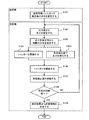
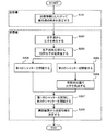
- FIG. 2 is a diagram illustrating a flowchart of an optical communication method using the optical communication system 100.
- the transmission control unit 122 sets the orientation of the polarizer 121 based on the transmitted information (step S101).
- the polarizer 121 is set to the first state in which the vertically or horizontally polarized photons are completely passed, and “0” is transmitted as the second information.
- the polarizer 121 is moved from the first state to the second state inclined by + 45 ° or ⁇ 45 ° with respect to the photon transmission direction.
- the direction of polarized light passing through in the first state may be set to other than longitudinally polarized light or laterally polarized light, and “0” and “1” as transmitted information may be reversed.
- the receiver 110 may be configured by appropriately changing the definition of the relationship between the polarization direction and the transmitted information.
- the reception control unit 119 generates photons from the photon source 111 (step S102).
- the timing for generating a photon from the photon source 111 is set so that the photon from the photon source 111 reaches the photon pair generating unit 112 after the nonlocal potential from the polarizer 121 reaches the photon pair generating unit 112. .
- the time when the orientation of the polarizer 121 is set is t 1
- the time required for the nonlocal potential from the polarizer 121 to reach the photon pair generation unit 112 is a
- the photon from the photon source 111 is
- the time required to reach the photon pair generating unit 112 is b
- the time t 2 for generating photons from the photon source 111 is expressed by equation (6).
- the times a and b can be calculated from the distance between the members.
- the time t 1 when the orientation of the polarizer 121 is set is determined based on the synchronization signal received from the transmission control unit 122 via the synchronization transmission path 140.
- the photon pair generation unit 112 When receiving a photon from the photon source 111, the photon pair generation unit 112 generates photons p and s which are correlated photon pairs (step S103). At this time, since the nonlocal potential from the polarizer 121 has already reached the photon pair generation unit 112, the polarization directions of the photons p and s are determined by the nonlocal potential. Specifically, when the polarizer 121 is in the first state in which the vertically or horizontally polarized photons are completely passed, the photon p from the photon pair generation unit 112 to the polarizer 121 is vertically or horizontally polarized light. And the other photon s is also longitudinally polarized light or transversely polarized light.
- the photon p directed from the photon pair generator 112 to the polarizer 121 is It is obliquely polarized light, and the other photon s is also obliquely polarized light.
- the reception control unit 119 closes the shutter 118 (step S104).
- the timing of closing the shutter 118 is after the photon p and s are generated in the photon pair generation unit 112 and before the photon p reaches the shutter 118.
- c be the time required for the photon pair generation unit 112 to generate photons p and s
- d be the time required for the photon p from the photon pair generation unit 112 to reach the shutter 118.
- time t 3 when closing the shutter 118 is expressed by equation (7). Since the photon moves at the speed of light, the times c and d can be calculated from the distance between the members.
- the reception detector 116 detects the photons s that have passed through the QWPs 113a and 113b and the double slit plate 114, and records the presence or absence of detection in the reception control unit 119 (step S105). Thereafter, the reception control unit 119 opens the shutter 118 (step S106).
- steps S102 to S106 are repeated a predetermined number of times at each measurement location while the reception detector 116 is moved by a predetermined distance by the drive unit 117 without changing the direction of the polarizer 121 (step S107) (step S107).
- steps S102 to S107 are executed 50 times (total 1000 times) at 20 locations.
- the reception control unit 119 determines the transmitted information by plotting the number of detected photons for each measurement location (step S109). Specifically, when interference is observed in the plot, the photon s before entering the QWPs 113a and 113b is longitudinally polarized light or laterally polarized light, so the other photon p is also longitudinally polarized light or laterally polarized light. . Therefore, it can be seen that the polarizer 121 on the optical path of the photon p is in the first state in which the vertically or horizontally polarized photon is completely passed, so the reception control unit 119 receives the information transmitted from the transmitter 120 as the first state. “1”, which is information of 1, is determined.
- the reception control unit 119 transmits the information transmitted from the transmitter 120. Is determined as “0” as the second information.
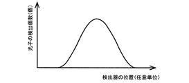
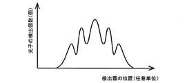
- FIG. 3A and 3B are diagrams showing schematic plots of results measured by the reception detector 116.
- FIG. 3A when the plot is a mountain shape having a single vertex, since no interference occurs, the photon s before entering the QWPs 113a and 113b is obliquely polarized light.
- FIG. 3B when the plot has a wave shape having a plurality of vertices, interference occurs, and thus the photons s before entering the QWPs 113a and 113b are longitudinally polarized light or laterally polarized light. .
- These determinations may be performed by the reception control unit 119 or a user.
- a non-local potential that cannot be observed is transmitted from the transmitter 120 to the receiver 110, and the polarization of photons that can be generated from the photon pair generator 112 is constrained by the non-local potential.
- the receiver 110 and the transmitter 120 of the optical communication system 100 are arranged at positions where photons can be transmitted and received. However, before the photons are actually emitted from the receiver 110 to the transmitter 120, the photons are blocked by the shutter 118. To do. For this reason, an eavesdropper cannot read information by stealing photons transmitted and received. Furthermore, since observable photons do not pass through the transmission path of information from the transmitter 120 to the receiver 110, it is difficult for an eavesdropper to know the transmission path itself.
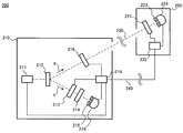
- FIG. 4 is a schematic configuration diagram of an optical communication system 200 according to the present embodiment.
- the optical communication system 200 includes a receiver 210 and a transmitter 220, and the receiver 210 and the transmitter 220 are connected by a communication path 230 that is an information transmission path.
- the communication path 230 is a free space, but at least a part of the communication path 230 may be an optical waveguide such as an optical fiber or PLC.
- a photon source 211 that outputs photons according to control by the reception control unit 219, and a photon pair generation unit 212 that generates a correlated photon pair when a photon enters from the photon source 211 are provided.
- One of the photon pairs is a photon p, and the other is a photon s.
- the photon p and the photon s have a correlation so as to have polarizations orthogonal to each other. That is, when the photon p is longitudinally polarized, the photon s is transversely polarized or vice versa.
- a BBO crystal ⁇ -BaB 2 O 4 crystal
- Substances or devices may be used.
- a second shutter 213 and a second polarizer 214 are provided in the emission direction of photons s by the photon pair generator 212, that is, on the optical path of the photons s.
- the second shutter 213 is opened to pass the photon s through the second polarizer 214 and closed to block the photon s from the second polarizer 214 according to control by the reception control unit 219. It is possible to switch between these states.
- any device that can be switched between open and closed mechanically or electromagnetically may be used.
- the second polarizer 214 passes a photon having a polarization in a predetermined direction and does not pass a photon having a polarization other than the predetermined direction.
- the second polarizer 214 since the horizontally polarized light is used as the polarized light in the predetermined direction, the second polarizer 214 passes when the photon s is horizontally polarized light, and passes through other polarized light, that is, vertically polarized light or obliquely polarized light. Do not pass.
- a slit plate 215 and a reception detector 216 are provided at a point where the photon s passes through the second polarizer 214.
- the slit plate 215 has a slit that restricts the photons s to be input to the reception detector 216 from a predetermined direction.
- the reception detector 216 outputs a predetermined signal to the reception control unit 219 when detecting the photon s.
- an APD active photodiode
- any device capable of detecting photons may be used.
- a first shutter 218 is provided in the emission direction of photons p by the photon pair generator 212, that is, on the optical path of the photons p.
- the first shutter 218 is between a state where the first shutter 218 is opened so as to pass the photon p through the communication path 230 and a state where the first shutter 218 is closed so as to block the photon p from the communication path 230.
- any device that can be switched between open and closed mechanically or electromagnetically may be used.
- a reception control unit 219 is connected to the photon source 211, the reception detector 216, the first shutter 218, and the second shutter 213.
- the reception control unit 219 electrically controls each member, communicates with the transmitter 220 via the synchronization transmission path 240, records the measured data, and inputs / outputs to / from the user.
- the reception control unit 219 includes an arbitrary computer or an electric circuit.
- a first polarizer 221 (polarizing plate) is provided in the incident direction of the photon p from the receiver 210, that is, on the optical path of the photon p.
- the first polarizer 221 has a first state in which a photon having polarized light in a predetermined direction passes completely, and a predetermined angle (for example, + 90 ° or ⁇ 90 °) with respect to the transmission direction of the photon from the first state. Switching between the tilted second state is possible.
- the polarizer 121 in the first state passes the vertically polarized photon, and the polarizer 121 in the second state passes the horizontally polarized photon.
- the first polarizer 221 is switched between the first state and the second state according to control by the transmission control unit 222.
- a slit plate 223 and a transmission detector 224 are provided at the point where the photon p passes through the first polarizer 221.
- the slit plate 223 has a slit that restricts the photon p to be input to the transmission detector 224 from a predetermined direction.
- the transmission detector 224 outputs a predetermined signal to the transmission control unit 222 when detecting the photon p.
- information is transmitted from the transmitter 220 to the receiver 210 according to the orientation of the first polarizer 221 as in the first embodiment. Therefore, the transmission detector 224 is not necessarily used for information transmission. Not necessary.
- the transmission detector 224 receives the photons from the receiver 210 to align the optical axis of the communication path 230 between the transmitter 220 and the receiver 210 or between the transmitter 220 and the receiver 210. It is used to measure the distance.
- a transmission control unit 222 is connected to the first polarizer 221 and the transmission detector 224.
- the transmission control unit 222 electrically controls each member, communicates with the receiver 210 via the synchronization transmission path 240, records the measured data, and inputs / outputs to / from the user.
- the transmission control unit 222 includes an arbitrary computer or an electric circuit.
- the receiver 210 and the transmitter 220 are connected by a synchronization transmission path 240.
- the synchronization transmission path 240 may be an arbitrary communication path such as an optical fiber communication path or a wireless communication path.
- the transmission control unit 222 synchronizes transmission / reception timing by transmitting a synchronization signal to the reception control unit 219 via the synchronization transmission path 240.
- Transmission / reception timing synchronization is performed by an arbitrary synchronization method using a signal indicating a transmission time, a periodic signal, or the like.
- FIG. 5 is a diagram showing a flowchart of an optical communication method using the optical communication system 200.
- the transmission control unit 222 changes the direction of the first polarizer 221 based on the transmitted information.
- Set (step S201) In this embodiment, when “1” is transmitted as the first information, the first polarizer 221 is set to the first state in which the vertically polarized photons are completely passed, and “0” is transmitted as the second information. In this case, the first polarizer 221 is set to the second state inclined from the first state by a predetermined angle (for example, + 90 ° or ⁇ 90 °).
- the direction of polarized light passing in the first state may be set to other than vertically polarized light, and “0” and “1” as transmitted information may be reversed.
- the receiver 210 may be configured by appropriately changing the definition of the relationship between the polarization direction and the transmitted information.
- the reception control unit 219 generates photons from the photon source 211 (step S202).
- the timing for generating a photon from the photon source 211 is such that the photon from the photon source 211 reaches the photon pair generating unit 212 after the delocalized potential from the first polarizer 221 reaches the photon pair generating unit 212.
- the timing can be calculated by Expression (6) as in the first embodiment.
- the photon pair generation unit 212 Upon receiving a photon from the photon source 211, the photon pair generation unit 212 generates photons p and s which are correlated photon pairs (step S203). At this time, since the delocalization potential from the first polarizer 221 has already reached the photon pair generation unit 212, the polarization directions of the photons p and s are determined by the delocalization potential. Specifically, when the first polarizer 221 is in the first state in which the vertically polarized photons are completely passed, the photon p heading from the photon pair generation unit 212 to the first polarizer 221 is vertically polarized. And the other photon s is transversely polarized.
- the photon pair generating unit When the first polarizer 221 is in the second state where the first polarizer 221 is tilted from the first state by a predetermined angle (in this case, + 90 ° or ⁇ 90 °) and passes the horizontally polarized light, the photon pair generating unit The photon p heading from 212 to the first polarizer 221 is laterally polarized, and the other photon s is vertically polarized.
- a predetermined angle in this case, + 90 ° or ⁇ 90 °
- the reception control unit 219 closes the first shutter 218 (step S204).
- the timing for closing the first shutter 218 is after photons p and s are generated in the photon pair generation unit 212 and before the photon p reaches the first shutter 218.
- the timing can be calculated by Expression (7) as in the first embodiment.
- the reception control unit 219 opens the second shutter 213 (step S205).
- the timing for opening the second shutter 213 is after the photon pair generation unit 212 generates photons p and s, but before the photon s reaches the second shutter 213.
- the time required for the photon s from the photon pair generation unit 212 to reach the second shutter 213 is represented by e.
- the time t 4 when opening the second shutter 213 is expressed by equation (8). Since the photon moves at the speed of light, the time e can be calculated from the distance between the members.
- the reception detector 216 detects the photon s that has passed through the second polarizer 214, and records the presence or absence of detection in the reception control unit 219 (step S206). Thereafter, the reception control unit 219 opens the first shutter 218 and closes the second shutter 213 (step S207).
- the reception control unit 219 determines the transmitted information using the result measured by the reception detector 216 (step S208). Specifically, when the photon is detected by the reception detector 216, the photon s before entering the second polarizer 214 is laterally polarized, so the other photon p is longitudinally polarized. Therefore, since it can be seen that the first polarizer 221 on the optical path of the photon p is in the first state in which the vertically polarized photon is completely passed, the reception control unit 219 receives the information transmitted from the transmitter 220 as the first state. “1”, which is information of 1, is determined.
- the reception control unit 219 is transmitted from the transmitter 220.
- the information is determined to be the second information “0”.
- optical communication system 200 in addition to the effects achieved by the first embodiment, it is possible to transmit one piece of information by only one transmission, so that the transmission speed can be further improved. It is.
- the present invention has been described using the terms of longitudinally polarized light, laterally polarized light, and obliquely polarized light as the polarization of photons, but the present invention is not limited to a specific direction of polarized light. In the practice of the present invention, polarized light in other directions may be used based on the symmetry of the polarized light. When using polarized light in other directions, the description in this specification may be read as appropriate.
Abstract
本発明は、従来よりも盗聴が困難な光通信方法およびシステムを提供する。本発明の一実施形態に係る光通信システム100は、相関光子対を発生させる光子対発生部112と、相関光子対の一方の光路上に設けられ、送信される情報に基づいて向きが変更可能な偏光子121と、相関光子対の一方の光路上において光子対発生部と偏光子との間に設けられ、相関光子対の一方を遮断可能なシャッター118と、相関光子対の他方の光路上に設けられた光子検出器116と、を備える。
Description
本発明は、光子を用いて情報の送受信を行う光通信方法およびシステムに関する。
近年、量子力学原理を応用した量子暗号通信について、研究および実験がなされている(非特許文献1、2)。従来の量子暗号通信は、通信経路に量子力学的な重ね合わせ状態の光子が存在することを前提として検討が行われている。重ね合わせ状態の光子は、盗聴者により観測されると、重ね合わせ状態から決定的な情報を持った固有状態へ遷移する。このような効果により、盗聴者は元の重ね合わせ状態を再現できないため、送受信される情報に影響を与えずに盗聴を行うことは不可能である。そのため、本来の送受信者は盗聴の有無を検知できることが安全性の担保となっている。
例えば、非特許文献3には、量子暗号通信としての光通信方法が開示されている。非特許文献3に記載の光通信方法では、送信者は光子に対して送信したい情報に応じた位相変調を行い、受信者に該光子を送信する。盗聴者が送信経路に介在して該光子を測定したとしても、送信者が用いた位相を知り得ないため、同じ位相変調を施した光子を受信者に再送信することはできない。その結果、送信者が送信した情報と受信者が受信した情報との間の不一致(エラー)が増加するため、盗聴者の存在を検知することが可能である。
H. Takesue et al., "Differential phase shift quantum key distribution experiment over 105 km fibre", New Journal of Physics, 2005, Vol. 7, 232
後藤仁, "量子暗号通信の仕組みと開発動向", 日本銀行金融研究所, 金融研究, 2009, 第28巻第3号, pp. 107-150
K. Inoue, "Quantum Key Distribution Technologies", IEEE Journal of Selected Topics in Quantum Electronics, 2006, Vol. 12 (4), pp. 888-896
M. Morimoto, "Resolution of Single Photon and Electron Interference Enigma", http://vixra.org/abs/1312.0097, 2013
上述した従来の光通信方法では、事後的に盗聴者の存在を検知可能であるとはいえ、盗聴者は通信経路で送受信される光子を測定すること自体は可能である。従来の光通信方法では、盗聴者の存在が検知された場合に不正に測定されたおそれのある光子に係る情報(例えば、暗号鍵)を廃棄すること等により盗聴に対処することはできるが、該光子が盗聴者に何らかの情報を与えてしまうことは否定できない。そのため、盗聴者による光子の測定自体を困難にすることがより望ましい。
本発明は、上述の問題に鑑みて行われたものであって、従来よりも盗聴が困難な光通信方法およびシステムを提供することを目的とする。
本発明の第1の態様は、光通信システムであって、相関光子対を発生させる光子対発生部と、前記相関光子対の一方の光路上に設けられ、送信される情報に基づいて向きが変更可能な偏光子と、前記相関光子対の前記一方の光路上において前記光子対発生部と前記偏光子との間に設けられ、前記相関光子対の前記一方を遮断可能なシャッターと、前記相関光子対の他方の光路上に設けられた光子検出器と、を備えることを特徴とする。
本発明の第2の態様は、光通信方法であって、送信される情報に基づいて偏光子の向きを設定することと、前記偏光子の向きが設定された後に、光子対発生部により相関光子対を発生することと、前記相関光子対が発生された後に、シャッターにより前記相関光子対の一方を遮断することと、前記相関光子対が発生された後に、検出器により前記相関光子対の他方を検出することと、を備え、前記相関光子対の前記一方の光路上に、前記シャッターおよび前記偏光子が配置されており、前記相関光子対の前記他方の光路上に、前記検出器が配置されていることを特徴とする。
本発明に係る光通信方法およびシステムによれば、偏光子の向きによって情報を送信し、シャッターによって相関光子対の一方を遮断するため、光子を読み取って盗聴を行うことが困難である。
以下、図面を参照して、本発明の実施の形態を説明するが、本発明は本実施形態に限定されるものではない。なお、以下で説明する図面で、同機能を有するものは同一符号を付け、その繰り返しの説明は省略することもある。
(第1の実施形態)
図1は、本実施形態に係る光通信システム100の概略構成図である。光通信システム100は、受信機110と送信機120とを備え、受信機110と送信機120との間は情報の伝達経路である通信路130により結ばれている。本実施形態において通信路130は自由空間であるが、通信路130の少なくとも一部は光ファイバやPLC等の光導波路でもよい。なお、受信機110および送信機120の名称は情報の送信の方向に基づいて定義されており、後述するように光子の送信の方向とは逆である。すなわち、情報の送信方向は送信機120から受信機110の方向であるが、光子の送信方向は受信機110から送信機120の方向である。
図1は、本実施形態に係る光通信システム100の概略構成図である。光通信システム100は、受信機110と送信機120とを備え、受信機110と送信機120との間は情報の伝達経路である通信路130により結ばれている。本実施形態において通信路130は自由空間であるが、通信路130の少なくとも一部は光ファイバやPLC等の光導波路でもよい。なお、受信機110および送信機120の名称は情報の送信の方向に基づいて定義されており、後述するように光子の送信の方向とは逆である。すなわち、情報の送信方向は送信機120から受信機110の方向であるが、光子の送信方向は受信機110から送信機120の方向である。
受信機110内には、受信制御部119による制御にしたがって光子を出力する光子源111と、光子源111から光子が入射されることによって相関光子対を発生させる光子対発生部112とが設けられる。該光子対のうち一方を光子pとし、他方を光子sとする。光子pと光子sとは互いに直交する偏光を有するように相関がある。すなわち、光子pが縦偏光のときは光子sは横偏光となり、又はその逆となる。本実施形態では光子対発生部112として、パラメトリック下方変換により互いに相関がある光子対を発生させるBBO結晶(β-BaB2O4結晶)を用いるが、互いに相関がある光子対を発生させる任意の物質又は装置を用いてよい。
光子対発生部112による光子sの出射方向、すなわち光子sの光路上には、2つのQWP113a、113b(1/4波長板)と、二重スリット板114とが設けられる。二重スリット板114は平行な2本のスリットを有する。第1のQWP113aは、それを通過した光子sが2本のスリットの一方に入射するように配置され、第2のQWP113bは、それを通過した光子sが2本のスリットの他方に入射するように配置される。
直線偏光の光子sがQWP113a、113bの高速軸に対して-45°又は45°の傾きで入射する場合(このときの光子sの偏光を斜め偏光とする)には、QWP113a、113bは光子sを円偏光に変換して出力する。一方、直線偏光の光子sがQWP113a、113bの高速軸に対して0°又は90°の傾きで入射する場合(このときの光子sの偏光を縦偏光又は横偏光とする)には、QWP113a、113bは光子sを直線偏光のまま出力する。さらに、QWP113a、113bが光子sを円偏光に変換する際の方向は、互いに逆である。具体的には、第1のQWP113aは光子sを右円偏光に変換し、第2のQWP113bは光子sを左円偏光に変換する(又はこの逆)。このような構成により、縦偏光又は横偏光の光子sがQWP113a、113bに入射する場合には二重スリット板114を通った後に干渉が発生し、斜め偏光の光子sがQWP113a、113bに入射する場合には二重スリット板114を通った後に干渉が発生しない。
光子sが二重スリット板114を通過する先、すなわち光子sの光路上には、スリット板115と、受信検出器116とが設けられる。スリット板115は、光子sが所定の方向から受信検出器116に入力されるように制限するスリットを有する。
受信検出器116は、光子sを検出すると受信制御部119に所定の信号を出力する。本実施形態では受信検出器116として、APD(アバランシェフォトダイオード)を用いるが、光子を検出可能な任意の装置を用いてよい。受信検出器116には、光子対発生部112による光子sの出射方向(光子sの光路)に対して垂直方向に受信検出器116を移動させる駆動部117が接続される。駆動部117は、モータやアクチュエータ等の任意の駆動部である。受信検出器116を駆動部117により移動させながら光子sの検出を繰り返すことによって、受信検出器116の各位置における光子sの検出数を取得することができる。
光子対発生部112による光子pの出射方向、すなわち光子pの光路上には、シャッター118が設けられる。シャッター118は、受信制御部119による制御にしたがって、光子pを通信路130に通すように開放された状態と、光子pを通信路130から遮断するように閉鎖された状態との間で切り替え可能である。シャッター118としては、機械的又は電磁的に開放と閉鎖とが切り替えられる任意の装置を用いてよい。
光子源111、受信検出器116およびシャッター118には、受信制御部119が接続される。受信制御部119は、各部材を電気的に制御し、送信機120と同期用伝送路140を介して通信し、測定されたデータの記録を行い、またユーザに対して入出力を行う。受信制御部119は、任意のコンピュータ又は電気回路を含む。
送信機120内において、受信機110からの光子pの入射方向、すなわち光子pの光路上には、偏光子121(偏光板)が設けられる。偏光子121は、所定の向きの偏光を有する光子を完全に通す第1の状態と、該第1の状態から光子の透過方向に関して+45°又は-45°傾いた第2の状態との間で切り替え可能である。本実施形態では該所定の向きの偏光として縦偏光又は横偏光を用いるため、第1の状態の偏光子121は縦偏光又は横偏光の光子を通し、第2の状態の偏光子121は斜め偏光の光子を通す。偏光子121は、送信制御部122による制御にしたがって、第1の状態と第2の状態との間で切り替えられる。
光子pが偏光子121を通過する先には、スリット板123と、送信検出器124とが設けられる。スリット板123は、光子pが所定の方向から送信検出器124に入力されるように制限するスリットを有する。送信検出器124は、光子pを検出すると送信制御部122に所定の信号を出力する。なお、後述するように本実施形態では偏光子121の向きによって送信機120から受信機110に情報を送信するため、情報送信のためには送信検出器124は必ずしも必要でない。送信検出器124は、受信機110からの光子を受信することによって、送信機120と受信機110との間で通信路130の光軸を合わせるため、又は送信機120と受信機110との間の距離を測定するために用いられる。
偏光子121および送信検出器124には、送信制御部122が接続される。送信制御部122は、各部材を電気的に制御し、受信機110と同期用伝送路140を介して通信し、測定されたデータの記録を行い、またユーザに対して入出力を行う。送信制御部122は、任意のコンピュータ又は電気回路を含む。
受信機110と送信機120とは、同期用伝送路140によって接続されている。同期用伝送路140は、光ファイバ通信路、無線通信路等、任意の通信路でよい。送信制御部122は、同期用伝送路140を介して受信制御部119に同期信号を送信することによって、送受信タイミングの同期を行う。送受信タイミングの同期は、送信時刻を示す信号や周期的な信号等を用いて、任意の同期方式により行われる。
ここで本発明の原理の説明を行う。従来、BBO結晶(光子対発生部)により発生される相関光子対(エンタングル光子対)において、一方の光子sが縦偏光|y>であれば他方の光子pは横偏向|x>、若しくはその逆であり、これらの偏光方向は観測するまで決定されず、これらの重ね合わせ状態である、と考えられてきた。すなわち、相関光子対は、光子sが縦偏光|y>で光子pが横偏向|x>である状態|y>s|x>pと、光子sが横偏光|x>で光子pが縦偏光|y>である状態|x>s|y>pとの重ね合わせ状態であると考えられてきた。この状態は式(1)で表される。
しかし、このような考え方では時間が逆転したようなパラドックスが発生し、原因と結果が入れ替わる等の特殊な状況が発生してしまう。それに対して、以下に述べるような非局在ポテンシャルの存在を認めると、従来の考え方を用いることなく説明が可能である。
すなわち、従来、偏光子(ポラライザ)等の偏光を揃えるデバイスを通った横偏光|x>および縦偏光|y>は、式(2)で表されるように+45°又は-45°傾いた偏光の重ね合わせであるとされていた。

ここで、|+>はx軸に対して+45°の偏光、|->はx軸に対して-45°の偏光を示す。古典的な電磁場ではこれは正しいが、単一光子のように分けられない光子にまで、この表式を用いることはパラドックスに繋がる。このような極少数の光子を取り扱う場合には、重ね合わせと考えるのではなく、空間中に普遍的に存在する非局在ポテンシャルを用いることによって上手く説明することができる。この場合に、式(2)に非局在ポテンシャル|ζ>を加えた式(3)が正しい表式と考える必要がある。

よって、非局在ポテンシャル|ζ>は式(4)により表される。

ここで、非局在ポテンシャル|ζ>の添え字は偏光子(光通信システム100における偏光子121)の向きを示しており、|ζ1>は横向き、|ζ2>は縦向きを示す。このように、偏光子が存在することによって、非局在ポテンシャル|ζ>が方向付けされる。すなわち、偏光子が横向きであれば非局在ポテンシャル|ζ1>となり、偏光子が縦向きであれば非局在ポテンシャル|ζ2>となる。
この非局在ポテンシャル|ζ>はMaxwell方程式に従うので、光速で偏光子から伝搬する。この伝搬した非局在ポテンシャル|ζ>が光子対を発生させるBBO結晶(光通信システム100における光子対発生部112)に到達すると、BBO結晶は、この方向付けられた非局在ポテンシャル|ζ>によって、発生可能な光子の偏光を決定づけられてしまう。
具体的には、BBO結晶が光子を発生する前に、BBO結晶から光子が出射される方向に存在する偏光子からBBO結晶に非局在ポテンシャル|ζ>が到達する。偏光子が横向きの場合には、非局在ポテンシャル|ζ1>が到達するため、BBO結晶は偏光子に向かう方向に横偏光|x>でしか光子pを発生できない。このとき相関光子対のうち他方の光子sは縦偏光|y>となる。一方、偏光子が縦向きの場合には、非局在ポテンシャル|ζ2>が到達するため、BBO結晶は偏光子に向かう方向に縦偏光|y>でしか光子pを発生できない。このとき相関光子対のうち他方の光子sは横偏光|x>となる。このように、BBO結晶から光子が出射される方向に存在する偏光子の向きによって、BBO結晶が発生可能な光子の偏光は拘束される。なお、ここでは縦偏光又は横偏光について説明したが、縦偏光又は横偏光から+45°又は-45°傾けた斜め偏光についても、同様に偏光子の向きによってBBO結晶が発生可能な光子の偏光は拘束される。
すなわち、BBO結晶では完全に相関のある光子対が始めから発生されているのであり、従来の考え方のように観測されるまで相関光子対が重ね合わせの状態にあるのではない。しかしながら、非局在ポテンシャルそのものは観測できないので、このような方向付けを感知することができない為に、光子対には不思議な相関があると従来考えられてきたのである。
非局在ポテンシャルは、確率振幅が<ζ1|ζ1>=0、<ζ2|ζ2>=0であることから、観測できないことがわかる。これは、式(4)をそのまま掛け合わせて、式(5)の関係を用いることによって容易に導かれる。

以上をまとめると、BBO結晶によって発生される相関光子対においては、一方が縦偏光|y>であれば他方は横偏向|x>(又はその逆)という完全な相関があるが、これは観測する又は観測しないに関わらず、光子対が発生されたときに決定されており、従来の考え方のように相関光子対が重ね合わせ状態にあるわけではない。この決定は、方向付けられた非局在ポテンシャル|ζ>が光子対発生前にBBO結晶に到達することによって為されている。
図2は、光通信システム100を用いる光通信方法のフローチャートを示す図である。まず、シャッター118が開放された状態で、送信制御部122は、送信される情報に基づいて偏光子121の向きを設定する(ステップS101)。本実施形態では、第1の情報として「1」を送信する場合には偏光子121を縦偏光又は横偏光の光子を完全に通す第1の状態にし、第2の情報として「0」を送信する場合には偏光子121を該第1の状態から光子の透過方向に関して+45°又は-45°傾いた第2の状態にする。第1の状態で通す偏光の向きを縦偏光又は横偏光以外に設定してもよく、また送信される情報としての「0」と「1」は逆でもよい。これらの場合には偏光の向きと送信される情報との関係の定義を適宜変更して受信機110を構成すればよい。
次に、受信制御部119は、光子源111から光子を発生させる(ステップS102)。光子源111から光子を発生させるタイミングは、偏光子121からの非局在ポテンシャルが光子対発生部112に到達した後に、光子源111からの光子が光子対発生部112に到達するように設定する。具体的には、偏光子121の向きが設定された時刻をt1、偏光子121からの非局在ポテンシャルが光子対発生部112に到達するのに要する時間をa、光子源111からの光子が光子対発生部112に到達するのに要する時間をbとすると、光子源111から光子を発生させる時刻t2は式(6)のように表される。
非局在ポテンシャルおよび光子は光速で運動するため、時間a、bは各部材間の距離から算出できる。偏光子121の向きが設定された時刻t1は、送信制御部122から同期用伝送路140を介して受信した同期信号に基づいて決定される。
光子対発生部112は、光子源111から光子を受けると、相関光子対である光子p、sを発生させる(ステップS103)。この時点で、偏光子121からの非局在ポテンシャルが既に光子対発生部112に到達しているため、該非局在ポテンシャルによって光子p、sの偏光方向が決定されている。具体的には、偏光子121が縦偏光又は横偏光の光子を完全に通す第1の状態である場合には、光子対発生部112から偏光子121へ向かう光子pは縦偏光又は横偏光であり、他方の光子sも縦偏光又は横偏光である。それに対して、偏光子121が第1の状態から+45°又は-45°傾けられて斜め偏光を通す第2の状態である場合には、光子対発生部112から偏光子121へ向かう光子pは斜め偏光であり、他方の光子sも斜め偏光である。
次に、受信制御部119は、シャッター118を閉鎖する(ステップS104)。シャッター118を閉鎖するタイミングは、光子対発生部112において光子p、sが発生された後であって、光子pがシャッター118に到達する前である。具体的には、光子対発生部112において光子p、sが発生されるのに要する時間をc、光子対発生部112からの光子pがシャッター118に到達するのに要する時間をdとすると、シャッター118を閉鎖する時刻t3は式(7)のように表される。光子は光速で運動するため、時間c、dは各部材間の距離から算出できる。
ステップS104と並行して、受信検出器116は、QWP113a、113bおよび二重スリット板114を通過した光子sを検出し、検出の有無を受信制御部119に記録する(ステップS105)。その後、受信制御部119は、シャッター118を開放する(ステップS106)。
本実施形態では測定結果における干渉の発生有無により送信情報(偏光子121の方向)を決定するため、検出を複数の測定箇所で、かつ各測定箇所で複数回行う必要がある。そのため、偏光子121の方向を変更せずに、駆動部117により受信検出器116を所定の距離ずつ移動させながら(ステップS107)、各測定箇所でステップS102~ステップS106を所定の回数繰り返す(ステップS108)。例えば、20箇所において50回ずつ(合計1000回)、ステップS102~ステップS107を実行する。
最後に、受信制御部119は、各測定箇所について測定された光子検出数をプロットすることによって、送信された情報を決定する(ステップS109)。具体的には、該プロットにおいて干渉の発生が認められる場合には、QWP113a、113bに入射する前の光子sは縦偏光又は横偏光であるため、他方の光子pも縦偏光又は横偏光である。したがって、光子pの光路上にある偏光子121が縦偏光又は横偏光の光子を完全に通す第1の状態であることがわかるため、受信制御部119は送信機120から送信された情報を第1の情報である「1」と決定する。一方、該プロットにおいて干渉の発生が認められない場合には、QWP113a、113bに入射する前の光子sは斜め偏光であるため、他方の光子pも斜め偏光である。したがって、光子pの光路上にある偏光子121が第1の状態から+45°又は-45°傾いた第2の状態であることがわかるため、受信制御部119は送信機120から送信された情報を第2の情報である「0」と決定する。
図3Aおよび3Bは、受信検出器116により測定される結果の模式的なプロットを示す図である。図3Aに示すように、プロットが単一の頂点を有する山型である場合には、干渉が発生していないため、QWP113a、113bに入射する前の光子sは斜め偏光である。一方、図3Bに示すように、プロットが複数の頂点を有する波型である場合には、干渉が発生しているため、QWP113a、113bに入射する前の光子sは縦偏光又は横偏光である。これらの判定は受信制御部119が行ってもよく、ユーザが行ってもよい。
本実施形態に係る光通信システム100は、観測できない非局在ポテンシャルが送信機120から受信機110に送信され、該非局在ポテンシャルにより光子対発生部112から発生し得る光子の偏光が拘束されることを利用して情報の伝達を行う。光通信システム100の受信機110および送信機120は、光子を送受信可能な位置に配置されているが、実際に光子が受信機110から送信機120に出射される前にシャッター118によって光子を遮断する。そのため、盗聴者は送受信される光子を盗んで情報を読み取ることはできない。さらに、送信機120から受信機110への情報の伝達経路には観測可能な光子が通らないため、盗聴者が該伝達経路を知ること自体も困難である。
(第2の実施形態)
第1の実施形態に係る光通信システム100では、干渉の有無を利用して統計的に情報を決定するため、1つの情報(「1」又は「0」)に対して複数回の送信が必要であった。それに対して、本実施形態では、1つの情報に対して1回の送信によって情報を決定することができる。
第1の実施形態に係る光通信システム100では、干渉の有無を利用して統計的に情報を決定するため、1つの情報(「1」又は「0」)に対して複数回の送信が必要であった。それに対して、本実施形態では、1つの情報に対して1回の送信によって情報を決定することができる。
図4は、本実施形態に係る光通信システム200の概略構成図である。光通信システム200は、受信機210と送信機220とを備え、受信機210と送信機220との間は情報の伝達経路である通信路230により結ばれている。本実施形態において通信路230は自由空間であるが、通信路230の少なくとも一部は光ファイバやPLC等の光導波路でもよい。
受信機210内には、受信制御部219による制御にしたがって光子を出力する光子源211と、光子源211から光子が入射されることによって相関光子対を発生させる光子対発生部212とが設けられる。該光子対のうち一方を光子pとし、他方を光子sとする。光子pと光子sとは互いに直交する偏光を有するように相関がある。すなわち、光子pが縦偏光のときは光子sは横偏光となり、又はその逆となる。本実施形態では光子対発生部212として、パラメトリック下方変換により互いに相関がある光子対を発生させるBBO結晶(β-BaB2O4結晶)を用いるが、互いに相関がある光子対を発生させる任意の物質又は装置を用いてよい。
光子対発生部212による光子sの出射方向、すなわち光子sの光路上には、第2のシャッター213と、第2の偏光子214(偏光板)とが設けられる。第2のシャッター213は、受信制御部219による制御にしたがって、光子sを第2の偏光子214に通すように開放された状態と、光子sを第2の偏光子214から遮断するように閉鎖された状態との間で切り替え可能である。第2のシャッター213としては、機械的又は電磁的に開放と閉鎖とが切り替えられる任意の装置を用いてよい。
第2の偏光子214は、所定の向きの偏光を有する光子を通し、該所定の向き以外の偏光を有する光子を通さない。本実施形態においては該所定の向きの偏光として横偏光を用いるため、第2の偏光子214は、光子sが横偏光の場合は通し、それ以外の偏光、すなわち縦偏光又は斜め偏光の場合は通さない。
光子sが第2の偏光子214を通過する先には、スリット板215と、受信検出器216とが設けられる。スリット板215は、光子sが所定の方向から受信検出器216に入力されるように制限するスリットを有する。
受信検出器216は、光子sを検出すると受信制御部219に所定の信号を出力する。本実施形態では受信検出器216として、APD(アバランシェフォトダイオード)を用いるが、光子を検出可能な任意の装置を用いてよい。
光子対発生部212による光子pの出射方向、すなわち光子pの光路上には、第1のシャッター218が設けられる。第1のシャッター218は、受信制御部219による制御にしたがって、光子pを通信路230に通すように開放された状態と、光子pを通信路230から遮断するように閉鎖された状態との間で切り替え可能である。第1のシャッター218としては、機械的又は電磁的に開放と閉鎖とが切り替えられる任意の装置を用いてよい。
光子源211、受信検出器216、第1のシャッター218および第2のシャッター213には、受信制御部219が接続される。受信制御部219は、各部材を電気的に制御し、送信機220と同期用伝送路240を介して通信し、測定されたデータの記録を行い、またユーザに対して入出力を行う。受信制御部219は、任意のコンピュータ又は電気回路を含む。
送信機220内において、受信機210からの光子pの入射方向、すなわち光子pの光路上には、第1の偏光子221(偏光板)が設けられる。第1の偏光子221は、所定の向きの偏光を有する光子を完全に通す第1の状態と、該第1の状態から光子の透過方向に関して所定の角度(例えば、+90°又は-90°)傾いた第2の状態との間で切り替え可能である。本実施形態では該所定の向きの偏光として縦偏光を用いるため、第1の状態の偏光子121は縦偏光の光子を通し、第2の状態の偏光子121は横偏光の光子を通す。第1の偏光子221は、送信制御部222による制御にしたがって、第1の状態と第2の状態との間で切り替えられる。
光子pが第1の偏光子221を通過する先には、スリット板223と、送信検出器224とが設けられる。スリット板223は、光子pが所定の方向から送信検出器224に入力されるように制限するスリットを有する。送信検出器224は、光子pを検出すると送信制御部222に所定の信号を出力する。なお、本実施形態では、第1の実施形態と同様に第1の偏光子221の向きによって送信機220から受信機210に情報を送信するため、情報送信のためには送信検出器224は必ずしも必要でない。送信検出器224は、受信機210からの光子を受信することによって、送信機220と受信機210との間で通信路230の光軸を合わせるため、又は送信機220と受信機210との間の距離を測定するために用いられる。
第1の偏光子221および送信検出器224には、送信制御部222が接続される。送信制御部222は、各部材を電気的に制御し、受信機210と同期用伝送路240を介して通信し、測定されたデータの記録を行い、またユーザに対して入出力を行う。送信制御部222は、任意のコンピュータ又は電気回路を含む。
受信機210と送信機220とは、同期用伝送路240によって接続されている。同期用伝送路240は、光ファイバ通信路、無線通信路等、任意の通信路でよい。送信制御部222は、同期用伝送路240を介して受信制御部219に同期信号を送信することによって、送受信タイミングの同期を行う。送受信タイミングの同期は、送信時刻を示す信号や周期的な信号等を用いて、任意の同期方式により行われる。
図5は、光通信システム200を用いる光通信方法のフローチャートを示す図である。まず、第2のシャッター213が閉鎖された状態であり、かつ第1のシャッター218が開放された状態で、送信制御部222は、送信される情報に基づいて第1の偏光子221の向きを設定する(ステップS201)。本実施形態では、第1の情報として「1」を送信する場合には第1の偏光子221を縦偏光の光子を完全に通す第1の状態にし、第2の情報として「0」を送信する場合には第1の偏光子221を該第1の状態から所定の角度(例えば+90°又は-90°)傾けた第2の状態にする。第1の状態で通す偏光の向きを縦偏光以外に設定してもよく、また送信される情報としての「0」と「1」は逆でもよい。これらの場合には偏光の向きと送信される情報との関係の定義を適宜変更して受信機210を構成すればよい。
次に、受信制御部219は、光子源211から光子を発生させる(ステップS202)。光子源211から光子を発生させるタイミングは、第1の偏光子221からの非局在ポテンシャルが光子対発生部212に到達した後に、光子源211からの光子が光子対発生部212に到達するように設定する。該タイミングは、第1の実施形態と同様に式(6)により算出できる。
光子対発生部212は、光子源211から光子を受けると、相関光子対である光子p、sを発生させる(ステップS203)。この時点で、第1の偏光子221からの非局在ポテンシャルが既に光子対発生部212に到達しているため、該非局在ポテンシャルによって光子p、sの偏光方向が決定されている。具体的には、第1の偏光子221が縦偏光の光子を完全に通す第1の状態である場合には、光子対発生部212から第1の偏光子221へ向かう光子pは縦偏光であり、他方の光子sは横偏光である。それに対して、第1の偏光子221が第1の状態から所定の角度(ここでは+90°又は-90°)傾けられて横偏光を通す第2の状態である場合には、光子対発生部212から第1の偏光子221へ向かう光子pは横偏光であり、他方の光子sは縦偏光である。
次に、受信制御部219は、第1のシャッター218を閉鎖する(ステップS204)。第1のシャッター218を閉鎖するタイミングは、光子対発生部212において光子p、sが発生された後であって、光子pが第1のシャッター218に到達する前である。該タイミングは、第1の実施形態と同様に式(7)により算出できる。
ステップS204と並行して、受信制御部219は、第2のシャッター213を開放する(ステップS205)。第2のシャッター213を開放するタイミングは、光子対発生部212において光子p、sが発生された後であって、光子sが第2のシャッター213に到達する前である。具体的には、式(6)、(7)で用いたt2、b、cに加え、光子対発生部212からの光子sが第2のシャッター213に到達するのに要する時間をeとすると、第2のシャッター213を開放する時刻t4は式(8)のように表される。光子は光速で運動するため、時間eは各部材間の距離から算出できる。
受信検出器216は、第2の偏光子214を通過した光子sを検出し、検出の有無を受信制御部219に記録する(ステップS206)。その後、受信制御部219は、第1のシャッター218を開放するするとともに、第2のシャッター213を閉鎖する(ステップS207)。
最後に、受信制御部219は、受信検出器216により測定された結果を用いて、送信された情報を決定する(ステップS208)。具体的には、受信検出器216で光子が検出される場合には、第2の偏光子214に入射する前の光子sは横偏光であるため、他方の光子pは縦偏光である。したがって、光子pの光路上にある第1の偏光子221が縦偏光の光子を完全に通す第1の状態であることがわかるため、受信制御部219は送信機220から送信された情報を第1の情報である「1」と決定する。一方、受信検出器216で光子が検出されない場合には、第2の偏光子214に入射する前の光子sは横偏光ではないため、他方の光子pは横偏光である。したがって、光子pの光路上にある第1の偏光子221が第1の状態から所定の角度傾けられた第2の状態であることがわかるため、受信制御部219は送信機220から送信された情報を第2の情報である「0」と決定する。
本実施形態に係る光通信システム200によれば、第1の実施形態が奏する効果に加え、1回のみの送信によって1つの情報を送信することができるため、送信速度をより向上させることが可能である。
本発明は、上述の実施形態に限定されることなく、本発明の趣旨を逸脱しない範囲において適宜変更可能である。
本明細書では、光子の偏光として縦偏光、横偏光および斜め偏光の語を用いて本発明の説明を行ったが、本発明は偏光の具体的な向きに限定されるものではない。本発明の実施においては、偏光の対称性に基づいて、その他の向きの偏光を用いてもよい。該その他の向きの偏光を用いる場合には、本明細書の記載を適宜読み替えればよい。
Claims (8)
- 相関光子対を発生させる光子対発生部と、
前記相関光子対の一方の光路上に設けられ、送信される情報に基づいて向きが変更可能な偏光子と、
前記相関光子対の前記一方の光路上において前記光子対発生部と前記偏光子との間に設けられ、前記相関光子対の前記一方を遮断可能なシャッターと、
前記相関光子対の他方の光路上に設けられた光子検出器と、
を備えることを特徴とする光通信システム。 - 前記光子対発生部は、前記情報に基づいて前記偏光子の向きが変更された後に、前記相関光子対を発生させるように構成されていることを特徴とする請求項1に記載の光通信システム。
- 前記シャッターは、前記相関光子対が発生された後であって、前記相関光子対の前記一方が前記シャッターに到達する前に、前記相関光子対の前記一方を遮断するように構成されていることを特徴とする請求項1又は2に記載の光通信システム。
- 前記偏光子を有する送信機と、
前記光子対発生部と、前記シャッターと、前記光子検出器とを有する受信機と、
を備えることを特徴とする、請求項1乃至3のいずれか1項に記載の光通信システム。 - 前記シャッターは、前記相関光子対の前記一方が前記受信機の外に出る前に、前記相関光子対の前記一方を遮断するように構成されていることを特徴とする、請求項4に記載の光通信システム。
- 前記相関光子対の前記他方の光路上において前記光子対発生部と前記光子検出器との間に設けられた1/4波長板および二重スリット板と、
前記相関光子対の前記他方が前記1/4波長板および前記二重スリット板を通過する際に発生する干渉の有無に基づいて、前記情報を決定する制御部と、
をさらに備えることを特徴とする、請求項1乃至5のいずれか1項に記載の光通信システム。 - 前記相関光子対の前記他方の光路上において前記光子対発生部と前記光子検出器との間に設けられた第2の偏光子と、
前記相関光子対の前記他方が前記第2の偏光子を通過するか否かに基づいて、前記情報を決定する制御部と、
をさらに備えることを特徴とする、請求項1乃至5のいずれか1項に記載の光通信システム。 - 送信される情報に基づいて偏光子の向きを設定することと、
前記偏光子の向きが設定された後に、光子対発生部により相関光子対を発生することと、
前記相関光子対が発生された後に、シャッターにより前記相関光子対の一方を遮断することと、
前記相関光子対が発生された後に、検出器により前記相関光子対の他方を検出することと、
を備え、
前記相関光子対の前記一方の光路上に、前記シャッターおよび前記偏光子が配置されており、
前記相関光子対の前記他方の光路上に、前記検出器が配置されていることを特徴とする光通信方法。
Priority Applications (1)
| Application Number | Priority Date | Filing Date | Title |
|---|---|---|---|
| US15/393,355 US9935721B2 (en) | 2014-07-02 | 2016-12-29 | Optical communication method and optical communication system |
Applications Claiming Priority (2)
| Application Number | Priority Date | Filing Date | Title |
|---|---|---|---|
| JP2014136718A JP5959577B2 (ja) | 2014-07-02 | 2014-07-02 | 光通信方法およびシステム |
| JP2014-136718 | 2014-07-02 |
Related Child Applications (1)
| Application Number | Title | Priority Date | Filing Date |
|---|---|---|---|
| US15/393,355 Continuation US9935721B2 (en) | 2014-07-02 | 2016-12-29 | Optical communication method and optical communication system |
Publications (1)
| Publication Number | Publication Date |
|---|---|
| WO2016002149A1 true WO2016002149A1 (ja) | 2016-01-07 |
Family
ID=55018730
Family Applications (1)
| Application Number | Title | Priority Date | Filing Date |
|---|---|---|---|
| PCT/JP2015/003018 WO2016002149A1 (ja) | 2014-07-02 | 2015-06-17 | 光通信方法およびシステム |
Country Status (3)
| Country | Link |
|---|---|
| US (1) | US9935721B2 (ja) |
| JP (1) | JP5959577B2 (ja) |
| WO (1) | WO2016002149A1 (ja) |
Cited By (1)
| Publication number | Priority date | Publication date | Assignee | Title |
|---|---|---|---|---|
| CN109274420A (zh) * | 2018-11-16 | 2019-01-25 | 西安电子科技大学 | 一种用于星地下行链路的纠缠光子对传输率估计方法 |
Families Citing this family (2)
| Publication number | Priority date | Publication date | Assignee | Title |
|---|---|---|---|---|
| KR102150232B1 (ko) * | 2020-04-22 | 2020-08-31 | 이우진 | 광학 암호통신 시스템의 광학 암호통신 방법 |
| KR102150233B1 (ko) * | 2020-04-22 | 2020-08-31 | 이우진 | 광학 암호통신 시스템의 광학 암호통신 방법 |
Citations (4)
| Publication number | Priority date | Publication date | Assignee | Title |
|---|---|---|---|---|
| JP2001339387A (ja) * | 2000-05-29 | 2001-12-07 | Akio Motoyoshi | 量子通信方法及び装置 |
| WO2005112335A1 (ja) * | 2004-05-17 | 2005-11-24 | Mitsubishi Denki Kabushiki Kaisha | 量子暗号通信装置 |
| US20100166187A1 (en) * | 2006-09-11 | 2010-07-01 | Alexei Trifonov | Qkd using high-altitude paltforms |
| JP2011217344A (ja) * | 2009-10-29 | 2011-10-27 | Hit Design:Kk | 量子通信装置,量子通信方法および量子情報処理方法 |
Family Cites Families (4)
| Publication number | Priority date | Publication date | Assignee | Title |
|---|---|---|---|---|
| US6314189B1 (en) * | 1997-10-02 | 2001-11-06 | Akio Motoyoshi | Method and apparatus for quantum communication |
| JP2001217344A (ja) * | 2000-02-04 | 2001-08-10 | Nec Corp | 半導体装置およびその製造方法 |
| JP4095536B2 (ja) * | 2003-10-30 | 2008-06-04 | 株式会社東芝 | 秘密鍵配布方法および秘密鍵配布装置 |
| EP1988649A1 (en) * | 2007-05-04 | 2008-11-05 | Nokia Siemens Networks Oy | Methods, systems, apparatuses and related computer program product for allocation of communication resources |
-
2014
- 2014-07-02 JP JP2014136718A patent/JP5959577B2/ja active Active
-
2015
- 2015-06-17 WO PCT/JP2015/003018 patent/WO2016002149A1/ja active Application Filing
-
2016
- 2016-12-29 US US15/393,355 patent/US9935721B2/en active Active
Patent Citations (4)
| Publication number | Priority date | Publication date | Assignee | Title |
|---|---|---|---|---|
| JP2001339387A (ja) * | 2000-05-29 | 2001-12-07 | Akio Motoyoshi | 量子通信方法及び装置 |
| WO2005112335A1 (ja) * | 2004-05-17 | 2005-11-24 | Mitsubishi Denki Kabushiki Kaisha | 量子暗号通信装置 |
| US20100166187A1 (en) * | 2006-09-11 | 2010-07-01 | Alexei Trifonov | Qkd using high-altitude paltforms |
| JP2011217344A (ja) * | 2009-10-29 | 2011-10-27 | Hit Design:Kk | 量子通信装置,量子通信方法および量子情報処理方法 |
Non-Patent Citations (1)
| Title |
|---|
| MASAHITO MORIMOTO: "Resolution of Single Photon and Electron Interference Enigma", VIXRA.ORG E-PRINT ARCHIVE, vol. 1312.009, December 2013 (2013-12-01), XP055249997, Retrieved from the Internet <URL:http://rxiv.org/pdf/1312.0097v1.pdf> [retrieved on 20150827] * |
Cited By (2)
| Publication number | Priority date | Publication date | Assignee | Title |
|---|---|---|---|---|
| CN109274420A (zh) * | 2018-11-16 | 2019-01-25 | 西安电子科技大学 | 一种用于星地下行链路的纠缠光子对传输率估计方法 |
| CN109274420B (zh) * | 2018-11-16 | 2020-05-05 | 西安电子科技大学 | 一种用于星地下行链路的纠缠光子对传输率估计方法 |
Also Published As
| Publication number | Publication date |
|---|---|
| US9935721B2 (en) | 2018-04-03 |
| JP2016015620A (ja) | 2016-01-28 |
| US20170111121A1 (en) | 2017-04-20 |
| JP5959577B2 (ja) | 2016-08-02 |
Similar Documents
| Publication | Publication Date | Title |
|---|---|---|
| US11411723B2 (en) | Apparatus and method for quantum enhanced physical layer security | |
| US10848303B2 (en) | Methods and apparatuses for authentication in quantum key distribution and/or quantum data communication | |
| US10862677B2 (en) | Dual rail compensation in phase encoded communication | |
| WO2009145392A1 (en) | System and method for quantum cryptography | |
| Pljonkin | Vulnerability of the synchronization process in the quantum key distribution system | |
| WO2007055683A2 (en) | Differential phase shift keying quantum key distribution | |
| WO2016002149A1 (ja) | 光通信方法およびシステム | |
| JP2017046044A (ja) | サニャックループ型非対称マッハ・ツェンダ干渉計及び量子鍵配送用受信装置 | |
| Lee et al. | Asymmetric delay attack on an entanglement-based bidirectional clock synchronization protocol | |
| JP2008514119A (ja) | Wdmネットワーク用のデュアルゲートqkdシステム | |
| Glejm et al. | Quantum key distribution in an optical fiber at distances of up to 200 km and a bit rate of 180 bit/s | |
| JP2008160368A (ja) | 偏光コーディング−位相コーディング間変換装置及びこれを用いた量子通信システム | |
| Pavičić | In quantum direct communication an undetectable eavesdropper can always tell Ψ from Φ Bell states in the message mode | |
| US20120269345A1 (en) | Integrated circuit (ic) card | |
| Klimov et al. | Two-parameter single-pass plug and play quantum cryptography without adjustment of states in the quantum channel | |
| Makarov | Quantum cryptography and quantum cryptanalysis | |
| WO2023277781A1 (en) | Encoder, decoder, systems and methods for d-dimensional frequency-encoded quantum communication and information processing | |
| JP4763166B2 (ja) | 光信号伝送装置及び光信号伝送装置の光信号伝送方法 | |
| Traina et al. | Review on recent groundbreaking experiments on quantum communication with orthogonal states | |
| Rumyantsev et al. | Modeling of quantum key distribution system for secure information transfer | |
| JP2013201523A (ja) | 量子暗号鍵配付システム、量子暗号鍵受信装置 | |
| Vybornyi et al. | Backflash light as a security vulnerability in quantum key distribution systems | |
| Trifonov et al. | Practical quantum cryptography | |
| JP2009147432A (ja) | 量子暗号送信器および量子暗号装置 | |
| Inoue et al. | Differential-phase-shift quantum key distribution utilizing decoy pulses |
Legal Events
| Date | Code | Title | Description |
|---|---|---|---|
| 121 | Ep: the epo has been informed by wipo that ep was designated in this application |
Ref document number: 15814948 Country of ref document: EP Kind code of ref document: A1 |
|
| NENP | Non-entry into the national phase |
Ref country code: DE |
|
| 122 | Ep: pct application non-entry in european phase |
Ref document number: 15814948 Country of ref document: EP Kind code of ref document: A1 |