WO2016002078A1 - ハイブリッド車両の制御装置 - Google Patents
ハイブリッド車両の制御装置 Download PDFInfo
- Publication number
- WO2016002078A1 WO2016002078A1 PCT/JP2014/067954 JP2014067954W WO2016002078A1 WO 2016002078 A1 WO2016002078 A1 WO 2016002078A1 JP 2014067954 W JP2014067954 W JP 2014067954W WO 2016002078 A1 WO2016002078 A1 WO 2016002078A1
- Authority
- WO
- WIPO (PCT)
- Prior art keywords
- torque
- output
- control
- hybrid vehicle
- shift
- Prior art date
- Legal status (The legal status is an assumption and is not a legal conclusion. Google has not performed a legal analysis and makes no representation as to the accuracy of the status listed.)
- Ceased
Links
Images





Classifications
-
- B—PERFORMING OPERATIONS; TRANSPORTING
- B60—VEHICLES IN GENERAL
- B60K—ARRANGEMENT OR MOUNTING OF PROPULSION UNITS OR OF TRANSMISSIONS IN VEHICLES; ARRANGEMENT OR MOUNTING OF PLURAL DIVERSE PRIME-MOVERS IN VEHICLES; AUXILIARY DRIVES FOR VEHICLES; INSTRUMENTATION OR DASHBOARDS FOR VEHICLES; ARRANGEMENTS IN CONNECTION WITH COOLING, AIR INTAKE, GAS EXHAUST OR FUEL SUPPLY OF PROPULSION UNITS IN VEHICLES
- B60K6/00—Arrangement or mounting of plural diverse prime-movers for mutual or common propulsion, e.g. hybrid propulsion systems comprising electric motors and internal combustion engines
- B60K6/20—Arrangement or mounting of plural diverse prime-movers for mutual or common propulsion, e.g. hybrid propulsion systems comprising electric motors and internal combustion engines the prime-movers consisting of electric motors and internal combustion engines, e.g. HEVs
- B60K6/42—Arrangement or mounting of plural diverse prime-movers for mutual or common propulsion, e.g. hybrid propulsion systems comprising electric motors and internal combustion engines the prime-movers consisting of electric motors and internal combustion engines, e.g. HEVs characterised by the architecture of the hybrid electric vehicle
- B60K6/48—Parallel type
-
- B—PERFORMING OPERATIONS; TRANSPORTING
- B60—VEHICLES IN GENERAL
- B60K—ARRANGEMENT OR MOUNTING OF PROPULSION UNITS OR OF TRANSMISSIONS IN VEHICLES; ARRANGEMENT OR MOUNTING OF PLURAL DIVERSE PRIME-MOVERS IN VEHICLES; AUXILIARY DRIVES FOR VEHICLES; INSTRUMENTATION OR DASHBOARDS FOR VEHICLES; ARRANGEMENTS IN CONNECTION WITH COOLING, AIR INTAKE, GAS EXHAUST OR FUEL SUPPLY OF PROPULSION UNITS IN VEHICLES
- B60K6/00—Arrangement or mounting of plural diverse prime-movers for mutual or common propulsion, e.g. hybrid propulsion systems comprising electric motors and internal combustion engines
- B60K6/20—Arrangement or mounting of plural diverse prime-movers for mutual or common propulsion, e.g. hybrid propulsion systems comprising electric motors and internal combustion engines the prime-movers consisting of electric motors and internal combustion engines, e.g. HEVs
- B60K6/50—Architecture of the driveline characterised by arrangement or kind of transmission units
- B60K6/54—Transmission for changing ratio
- B60K6/547—Transmission for changing ratio the transmission being a stepped gearing
-
- B—PERFORMING OPERATIONS; TRANSPORTING
- B60—VEHICLES IN GENERAL
- B60W—CONJOINT CONTROL OF VEHICLE SUB-UNITS OF DIFFERENT TYPE OR DIFFERENT FUNCTION; CONTROL SYSTEMS SPECIALLY ADAPTED FOR HYBRID VEHICLES; ROAD VEHICLE DRIVE CONTROL SYSTEMS FOR PURPOSES NOT RELATED TO THE CONTROL OF A PARTICULAR SUB-UNIT
- B60W10/00—Conjoint control of vehicle sub-units of different type or different function
- B60W10/02—Conjoint control of vehicle sub-units of different type or different function including control of driveline clutches
-
- B—PERFORMING OPERATIONS; TRANSPORTING
- B60—VEHICLES IN GENERAL
- B60W—CONJOINT CONTROL OF VEHICLE SUB-UNITS OF DIFFERENT TYPE OR DIFFERENT FUNCTION; CONTROL SYSTEMS SPECIALLY ADAPTED FOR HYBRID VEHICLES; ROAD VEHICLE DRIVE CONTROL SYSTEMS FOR PURPOSES NOT RELATED TO THE CONTROL OF A PARTICULAR SUB-UNIT
- B60W10/00—Conjoint control of vehicle sub-units of different type or different function
- B60W10/04—Conjoint control of vehicle sub-units of different type or different function including control of propulsion units
- B60W10/06—Conjoint control of vehicle sub-units of different type or different function including control of propulsion units including control of combustion engines
-
- B—PERFORMING OPERATIONS; TRANSPORTING
- B60—VEHICLES IN GENERAL
- B60W—CONJOINT CONTROL OF VEHICLE SUB-UNITS OF DIFFERENT TYPE OR DIFFERENT FUNCTION; CONTROL SYSTEMS SPECIALLY ADAPTED FOR HYBRID VEHICLES; ROAD VEHICLE DRIVE CONTROL SYSTEMS FOR PURPOSES NOT RELATED TO THE CONTROL OF A PARTICULAR SUB-UNIT
- B60W10/00—Conjoint control of vehicle sub-units of different type or different function
- B60W10/04—Conjoint control of vehicle sub-units of different type or different function including control of propulsion units
- B60W10/08—Conjoint control of vehicle sub-units of different type or different function including control of propulsion units including control of electric propulsion units, e.g. motors or generators
-
- B—PERFORMING OPERATIONS; TRANSPORTING
- B60—VEHICLES IN GENERAL
- B60W—CONJOINT CONTROL OF VEHICLE SUB-UNITS OF DIFFERENT TYPE OR DIFFERENT FUNCTION; CONTROL SYSTEMS SPECIALLY ADAPTED FOR HYBRID VEHICLES; ROAD VEHICLE DRIVE CONTROL SYSTEMS FOR PURPOSES NOT RELATED TO THE CONTROL OF A PARTICULAR SUB-UNIT
- B60W10/00—Conjoint control of vehicle sub-units of different type or different function
- B60W10/10—Conjoint control of vehicle sub-units of different type or different function including control of change-speed gearings
-
- B—PERFORMING OPERATIONS; TRANSPORTING
- B60—VEHICLES IN GENERAL
- B60W—CONJOINT CONTROL OF VEHICLE SUB-UNITS OF DIFFERENT TYPE OR DIFFERENT FUNCTION; CONTROL SYSTEMS SPECIALLY ADAPTED FOR HYBRID VEHICLES; ROAD VEHICLE DRIVE CONTROL SYSTEMS FOR PURPOSES NOT RELATED TO THE CONTROL OF A PARTICULAR SUB-UNIT
- B60W20/00—Control systems specially adapted for hybrid vehicles
-
- Y—GENERAL TAGGING OF NEW TECHNOLOGICAL DEVELOPMENTS; GENERAL TAGGING OF CROSS-SECTIONAL TECHNOLOGIES SPANNING OVER SEVERAL SECTIONS OF THE IPC; TECHNICAL SUBJECTS COVERED BY FORMER USPC CROSS-REFERENCE ART COLLECTIONS [XRACs] AND DIGESTS
- Y02—TECHNOLOGIES OR APPLICATIONS FOR MITIGATION OR ADAPTATION AGAINST CLIMATE CHANGE
- Y02T—CLIMATE CHANGE MITIGATION TECHNOLOGIES RELATED TO TRANSPORTATION
- Y02T10/00—Road transport of goods or passengers
- Y02T10/60—Other road transportation technologies with climate change mitigation effect
- Y02T10/62—Hybrid vehicles
Definitions
- the present invention relates to a hybrid vehicle control apparatus that controls output torque of two drive sources in accordance with a shift of a transmission in a hybrid vehicle having two drive sources as power sources such as an engine and an electric motor.
- a hybrid vehicle that transmits a compensation torque from an electric motor to a driving wheel when the clutch is released and torque transmission from the engine to the driving wheel is cut to perform a shift (for example, a patent) Reference 1).
- an electric motor is provided so that torque can be transmitted to the drive wheels even when the clutch is released. Then, during the shift in which the clutch is disengaged and the torque transmission from the engine to the driving wheel is cut off, the torque is compensated by the electric motor for the driving wheel and the torque transmission between the engine and the driving wheel is cut off. Torque loss is suppressed.
- the compensation torque a torque equivalent to the engine torque during the shift is compensated so that the output torque does not change before and after the shift, and the output equivalent to the output torque from the engine as an electric motor is provided. What can obtain torque is required. In this case, the cost and size of the apparatus are increased.
- the electric motor is downsized and uses an engine whose output is lower than the engine output, the torque fluctuation before and after the shift increases.
- the present invention has been made paying attention to the above problems, and controls a hybrid vehicle capable of suppressing torque fluctuations before and after shifting even if the maximum output of the second drive source is less than the maximum output of the first drive source.
- An object is to provide an apparatus.
- the present invention provides: Control means for performing compensation control to compensate for torque loss of the first drive source with output torque of the second drive source during release of the clutch interposed in the power transmission system of the first drive source and the drive wheel;
- the control means performs pre-shift output reduction control for reducing the output torque of at least one of both drive sources from the normal output torque according to the driving state before starting the compensation control.
- a control device for a hybrid vehicle is provided.
- the clutch is disengaged, the transmission of torque from the first drive source to the driving wheels is cut off, the shifting is performed, and compensation control is performed while the clutch is released to perform the second drive Transmits the compensation torque from the power source to the drive wheels.
- output reduction control before shifting is performed in which the output torque of at least one of the two drive sources is reduced from the normal output torque corresponding to the driving state. For this reason, even if the maximum output of the second drive source is lower than the maximum output of the first drive source, it is possible to suppress torque fluctuation before and after the shift as compared with the case where the output reduction control before the shift is not performed. .
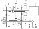
- FIG. 1 is an overall view showing a schematic structure of a hybrid vehicle control device of Embodiment 1 and a drive system of the hybrid vehicle. It is a skeleton figure of the automatic transmission applied to the control apparatus of the said hybrid vehicle, It is a figure explaining the torque summing mode and the torque compensation mode.
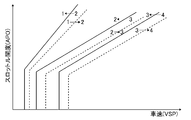
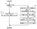
- 4 is a shift map of the automatic transmission. 4 is a flowchart showing a flow of torque control processing at the time of gear shifting in the hybrid vehicle control device of the first embodiment.
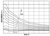
- 3 is a vehicle target drive torque map used in the hybrid vehicle control apparatus of the first embodiment.
- 3 is a pre-shift motor torque map used in the hybrid vehicle control apparatus of the first embodiment.
- FIG. 6 is a torque fluctuation diagram showing an operation example when the battery SOC is relatively low in the hybrid vehicle control apparatus of the first embodiment.
- 5 is a time chart showing an operation example at the time of shifting when the battery SOC is relatively small in the control device for a hybrid vehicle of the first embodiment.
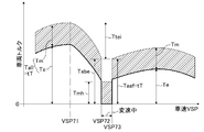
- FIG. 6 is a torque fluctuation diagram showing an operation example at the time of shifting when the battery SOC is relatively large in the control device for a hybrid vehicle of the first embodiment.
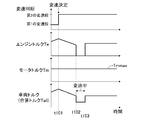
- 6 is a time chart showing an operation example at the time of shifting when the battery SOC is relatively large in the control device for a hybrid vehicle of the first embodiment.
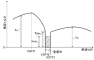
- FIG. 3 is a torque fluctuation diagram of a comparative example with the hybrid vehicle control device of the first embodiment.
- FIG. 3 is a torque fluctuation diagram of a comparative example with the hybrid vehicle control device of the first embodiment.
- FIG. 11 is a torque fluctuation diagram showing an example of operation during shifting of the control device for a hybrid vehicle in the second embodiment.
- FIG. 10 is a torque fluctuation diagram illustrating an operation example during a shift of the hybrid vehicle control device of the third embodiment.
- FIG. 10 is a torque fluctuation diagram showing an example of operation of the hybrid vehicle control apparatus according to Embodiment 4 during shifting.
- FIG. 10 is a torque fluctuation diagram illustrating an example of an operation at the time of shifting of a control device for a hybrid vehicle of a fifth embodiment.
- FIG. 10 is a torque fluctuation diagram showing an operation example at the time of shifting of a modification of the control device for a hybrid vehicle of the fifth embodiment. It is the schematic which shows the other drive transmission system which can apply this invention.
- FIG. 1 is an overall view showing a schematic structure of a control device for a hybrid vehicle and a drive system thereof according to a first embodiment.
- the hybrid vehicle includes an engine 10 corresponding to a first drive source and an electric motor 20 corresponding to a second drive source as drive sources.
- An automatic transmission 30 is interposed in the drive transmission path between the engine 10 and the drive wheels W.
- the automatic transmission 30 includes a main input shaft 31 to which the engine 10 is connected, and a main output shaft 32 that outputs torque to the drive wheels W. Further, the main input shaft 31 is provided with a first sub input shaft 31 a and a second sub input shaft 31 b that can run idle with respect to the main input shaft 31 in parallel with the main input shaft 31. Similarly, a first sub output shaft 32 a, a second sub output shaft 32 b, and a third sub output shaft 32 c that can idle and rotate with respect to the main output shaft 32 are also parallel to the main output shaft 32. Is provided. A plurality of drive gear sets 33, 34, 35, and 36 having different gear ratios are provided between the input shafts 31, 31a, and 31b and the output shafts 32, 32a, 32b, and 32c.
- each of the engagement clutches 37 to 39 uses a dog clutch that does not have a synchronization mechanism, and the hub moves to three positions in the axial direction to switch the engagement state. That is, at the center position of the hub at three positions, the hub does not engage with each of the adjacent sub input shafts 31a and 31b, each of the sub output shafts 32a to 32c, and any of the splines provided on the case, and torque transmission is not possible. Disconnected neutral state.
- the hub When moving from the neutral state in either the forward or reverse axial direction (left and right in the figure), the hub is provided on each of the sub input shafts 31a and 31b, each of the sub output shafts 32a to 32c, and the case. Torque is transmitted by engaging with any of the splines. At the time of shifting the automatic transmission 30, one of the engagement clutches 37 to 39 is released, and the driving force of the engine 10 is not transmitted from the main output shaft 32 to the driving wheels W, and switching from releasing to fastening is performed. The clutch is engaged in synchronism with the input and output rotations of the clutch to change the speed.
- each engagement clutch 37 to 39 is switched by moving the hub by the actuators 37a, 38a, 39a, respectively.
- These actuators 37 a, 38 a, 39 a are driven by hydraulic pressure or electric power, and the drive is controlled by the transmission controller 40.
- the shift controller 40 is configured by an electronic control unit (ECU) that includes a microcomputer.
- the automatic transmission 30 can form a torque addition mode and a torque compensation mode as torque transmission modes to the drive wheels W formed based on switching by the clutches 37 to 39.
- the torque summation mode is a mode in which output torques of the engine 10 and the electric motor 20 can be summed and transmitted to the drive wheels W.
- the torque summing mode can be formed by engaging the first engagement clutch 37 and the third engagement clutch 39 in the right direction in the drawing.
- the engine torque Te which is the output torque of the engine 10 indicated by the solid line in the figure
- the motor torque Tm which is the output torque of the electric motor 20 indicated by the dotted line in the figure
- the torque addition mode only the engine torque Te can be output to the drive wheels W if the output torque of the electric motor 20 is set to zero.
- one of the engagement clutches 37 to 39 is released so that the engine torque Te is not transmitted to the main output shaft 32.
- the motor torque Tm is transmitted via the main output shaft 32. Is transmitted to the drive wheels W.
- it can be formed by switching the first engagement clutch 37 from the engagement state of both engagement clutches 37 and 39 shown in FIG. 2 to the neutral state.
- the motor torque Tm of the electric motor 20 can be transmitted to the drive wheels W when the clutch that interrupts the torque transmission of the engine 10 is released or engaged.
- the switching of the torque transmission mode is performed in accordance with the shift control by the shift controller 40.
- the shift control executed by the shift controller 40 is a well-known control, and is set in advance based on the vehicle speed VSP detected by the vehicle speed sensor 61 and the throttle opening APO detected by the throttle opening sensor 62.
- the gear position is determined by the shift map.
- FIG. 3 shows an example of the shift map.
- the drive torque controller 50 controls the output torque of the engine 10 and the electric motor 20.
- this output torque control during normal travel (during non-shifting), the output torque of the engine 10 and the electric motor 20 is obtained so that the vehicle target drive torque tT is obtained as the normal output torque according to the driving state.
- the vehicle target drive torque tT is calculated based on a preset target drive torque map based on the throttle opening APO and the vehicle speed VSP, as is well known.
- FIG. 5 shows an example of the vehicle target drive torque map.
- the vehicle target drive torque is set lower than the low vehicle speed at a relatively high vehicle speed, and the large throttle opening is performed at a relatively small throttle opening. Set lower than the degree.
- the drive torque controller 50 is configured by an electronic control unit (ECU) including a microcomputer.
- ECU electronice control unit
- a signal from the sensor group 60 including the vehicle speed sensor 61 and the throttle opening sensor 62 is directly input to the controllers 40 and 50 or indirectly via a CAN communication line (not shown).
- FIG. 4 is a flowchart showing the process flow of the torque control during shifting by the drive torque controller 50.
- the torque control at the time of shifting shown in this flowchart is started when the shift controller 40 determines that an upshift is to be performed, and the combined torque before the shift before the upshift and the compensation torque during the release of the clutch. Is a process of calculating and outputting.
- the upshift is determined when the operating point determined by the vehicle speed VSP and the throttle opening APO crosses the shift line indicated by the dotted line in FIG. 3 from left to right.
- output reduction control before shifting is performed to reduce the combined torque before shifting corresponding to the output torque at the normal time in accordance with an operation state to be described later.
- the shift determination timing for starting the torque control at the time of shift is such that the shift line is earlier than the conventional shift determination timing at which the pre-shift output reduction control is not executed. Is set.
- the shift torque control may be started by predicting the shift execution at a timing earlier than the shift determination timing by the normally used shift line by the time for outputting the pre-shift combined torque.
- step S1 which proceeds first after the shift is determined, it is determined whether or not a shift is being performed.
- the process proceeds to step S2 during a shift in which the automatic transmission 30 is performing a shift.
- any one or two of the engagement clutches 37 to 39 are released (neutral state) and the output torque of the engine 10 is not transmitted to the drive wheels W in the automatic transmission 30. It means the period from the shift stage before shifting to the shift stage after shifting.
- the automatic transmission 30 replaces the clutch different from the clutch being released.
- step S2 the engine torque Te is set to 0, and the compensation control is performed to set the motor torque Tm to a preset compensation torque Tmh.
- the compensation torque Tmh is the maximum torque of the electric motor 20. That is, in the first embodiment, during the shift where the engine torque Te is not transmitted to the drive wheel W (during clutch release), the supplementary torque Tmh is transmitted from the electric motor 20 to the drive wheel W, so that torque loss during the shift is eliminated. Suppressed.
- step S1 when the gear is not being shifted, that is, in step S3 that is before the gear shift and before the start of the compensation control, the vehicle target drive torque tT is calculated or read, and the procedure proceeds to the next step S4.
- the vehicle target drive torque tT is calculated based on a preset target drive torque map based on the throttle opening APO and the vehicle speed VSP as described above.
- step S4 after calculating the total torque decrease amount Ttei before shifting, the process proceeds to step S5. That is, in the first embodiment, during traveling, the output torque of the engine 10 and the electric motor 20 is set so that the total torque Tall obtained by adding the engine torque Te and the motor torque Tm becomes the vehicle target drive torque tT. I have control.
- the torque change before and after the shift is suppressed by executing the output decrease control before the shift that reduces the total torque Tall according to the driving state. Yes.
- the total torque decrease amount Ttei before the shift is obtained by setting the pre-shift total torque Tabe to the post-shift total torque Taaf that is lower than the vehicle target drive torque tT, as shown in FIGS. Is set to match.
- step S5 following step S4 in which the total torque reduction amount Ttei is calculated, the pre-shift motor torque Tmbe is calculated based on the pre-shift motor torque map shown in FIG. 6, and the process proceeds to the next step S6. Further, in step S6, based on the pre-shift motor torque, the pre-shift engine torque Tebe for achieving the total torque reduction amount Ttei is calculated.
- a reduction amount of the motor torque Tm is determined based on the battery SOC, and the engine torque Te is reduced by an insufficiency of the total torque reduction amount Ttei due to the reduction amount of the motor torque Tm. I am doing so.
- the battery SOC is a value corresponding to the charge amount of a battery not shown.
- the pre-shift motor torque Tmbe shown in the pre-shift motor torque map of FIG. 6 is the maximum motor torque Tmmax when the battery SOC is higher than the high set value SOChi.
- the pre-shift motor torque Tmbe is set to zero.
- the pre-shift motor torque Tmbe increases as the battery SOC increases between 0 and the maximum motor torque Tmmax according to the battery SOC.
- the vertical axis represents the vehicle torque and the horizontal axis represents the vehicle speed, and shows the torque change accompanying the increase in the vehicle speed at the time of the upshift due to acceleration.
- the acceleration performance is inferior to that in which acceleration is performed with the vehicle torque obtained by adding the motor torque Tm to the engine torque Te.
- the compensation torque (motor torque) Tmh In order to suppress the torque fluctuation before and after the shift, it is preferable to increase the compensation torque (motor torque) Tmh.
- a relatively large electric motor is required, resulting in an increase in cost and weight. .
- FIG. 12 is an example in which the output torque corresponding to the required torque is obtained by the combined torque of the engine torque Te and the motor torque Tm before and after the shift. In this case, Excellent acceleration. However, since the motor torque Tm is added before the start of the compensation control, even if a large torque motor is used, there is a difference by the engine torque Te between before the shift and during the shift. The torque fluctuation becomes larger. As described above, in the comparative examples shown in FIGS. 11 and 12, it is difficult to suppress the torque fluctuation before and after the shift while securing the high acceleration performance by using the motor torque Tm for the acceleration without wasting it.
- FIG. 7 In the example of operation shown in FIG. 7, as the vehicle speed VSP increases, a shift-up shift is performed from the first gear to the second gear.
- the shift start vehicle speed VSP72 and the shift end vehicle speed are shown.
- the automatic transmission 30 is shifted with the VSP 73. From the vehicle speed VSP72 at the start of shifting to the vehicle speed VSP73 at the end of shifting is during the release (shifting) of any of the engagement clutches 37 to 39, the drive transmission between the engine 10 and the drive wheels W is cut off.
- the total torque Tall which is the sum of both torques of the motor torque Tm, is output. Therefore, compared with the output of only engine torque Te, high acceleration performance can be obtained.
- the first gear position is such that the first engagement clutch 37 and the third engagement clutch 39 are engaged in the right direction, and the second engagement clutch 38 is engaged. It can be formed in a neutral state.
- the second shift stage can be formed from the first shift stage by bringing the first engagement clutch 37 into the neutral state and engaging the second engagement clutch 38 in the right direction in the drawing.
- the total torque Tall at both speeds is output so as to coincide with the vehicle target drive torque tT.
- the maximum motor torque Tmmax is output as the motor torque Tm, and the motor torque Tm is efficiently generated. Used for acceleration.
- the compensation control for outputting the compensation torque Tmh by the motor torque Tm is executed based on the flow of the processing from step S1 to S2.
- the first engagement clutch 37 is set to the neutral state
- the third engagement clutch 39 is engaged to the right side
- the automatic transmission 30 is set to the torque compensation mode.
- the motor torque Tm is transmitted to the drive wheel W while shifting the transmission of the engine torque Te to the drive wheel W.
- the total torque Tall transmitted to the drive wheels W is set to the normal output torque.
- Pre-shift output reduction control is performed to reduce the total torque Tall according to a certain vehicle target drive torque tT.
- the total torque Tall is set to the vehicle target drive torque (normal time) between the shifting start vehicle speed VSP72 starting from the shifting determination vehicle speed VSP71, which is the vehicle speed when the shifting is determined in FIG. Output torque) tT.
- the total torque decrease amount Ttei at this time is based on the calculation in step S4 of FIG.
- the pre-shift total torque Tab that is the total torque Tall of the shift start vehicle speed VSP72 is made to coincide with the post-shift total torque Taaf that is the total torque Tall after the shift.
- the total torque decrease amount Ttei is calculated.
- the total torque reduction amount Ttei can be achieved by reducing either or both of the motor torque Tm and the engine torque Te.
- the motor torque Tm is reduced to 0, and the engine torque is further reduced. Te is lowered. That is, when the battery SOC is lower than the low set value SOClo based on the process in step S5 in FIG. 4, the electric power is preserved, so that the pre-shift motor torque Tmbe is set to 0 as shown in FIG. . Therefore, in the subsequent step S6, the pre-shift engine torque Teve that can obtain the pre-shift total torque Tab after setting the pre-shift motor torque Tmbe to 0 is determined.
- FIG. 8 is a time chart showing each torque output state during the operation of FIG. As shown in this figure, when the total torque Tall corresponding to the vehicle target driving torque (normal output torque) tT is decreased to the total torque before shifting Tabe, the motor torque Tm is decreased from the time t81, The engine torque Te is decreased from time t82.
- the compensation torque Tmh is a maximum motor torque Tmmax that is the maximum torque of the electric motor 20.
- the motor torque Tm is the maximum motor torque Tmmax. To maintain.
- the first embodiment can suppress changes in vehicle torque before, during, and after shifting.
- high acceleration performance can be obtained by adding the maximum motor torque Tmmax to the total torque Tall before and after the shift.
- FIGS. 9 and 10 show operations when the battery SOC is sufficiently secured.
- the motor torque Tm is maintained at the maximum motor torque Tmmax before, during, and after the shift. Therefore, the driving force of the electric motor 20 can be used effectively.
- the pre-shift total torque Tabe is achieved by reducing the engine torque Te by the total torque decrease amount Ttei.
- the pre-shift total torque Tabe is reduced from the shift determination vehicle speed VSP71, and the pre-shift total torque Tab at the shift start vehicle speed VSP72 matches the post-shift total torque Taaf.
- the output reduction control before shifting is executed. In this case, the control target is only the engine torque Te, and control becomes easy.
- the hybrid vehicle control apparatus of the first embodiment includes an automatic transmission 30 interposed in a drive transmission system of an engine 10 and a drive wheel W as a first drive source, A first engagement clutch 37 to a third engagement clutch 39, which are interposed in a power transmission system between the engine 10 and the drive wheels W and are released during shifting of the automatic transmission 30; An electric motor 20 as a second drive source provided so that torque can be transmitted to the drive wheel W during disengagement of any of the first engagement clutch 37 to the third engagement clutch 39; A drive torque controller 50 as control means for performing compensation control to compensate for torque loss of the engine 10 with the output torque of the electric motor 20 during release of the clutch; With Before starting the compensation control, the drive torque controller 50 reduces the output torque of at least one of the engine 10 and the electric motor 20 from the normal output torque (vehicle target drive torque tT) according to the driving state.
- the output reduction control before shifting is performed. Therefore, even when the maximum motor torque Tmmax of the electric motor 20 is lower than the maximum output of the engine 10, torque fluctuations before and after compensation control are compared with those in which output reduction control before shifting is not performed. Can be suppressed.
- the control device for the hybrid vehicle of the first embodiment is The second drive source is an electric motor 20 driven by electric power, Before starting the compensation control, the drive torque controller 50 outputs a combined torque Tall that is a combination of the engine torque Te that is the output torque of the engine 10 and the motor torque Tm that is the output torque of the electric motor 20.
- the ratio of the engine torque reduction amount as the first drive source and the motor torque reduction amount during the output reduction control before shifting is determined based on the battery SOC. Therefore, when the battery SOC decreases, the battery charge amount can be preserved by decreasing the motor torque Tm.
- the reduction of the motor torque Tm is suppressed to effectively use the battery power, and the total torque Tall is reduced before the shift by the decrease of the engine torque Te.
- the torque fluctuation after the shift can be suppressed.
- the motor torque Tm can be effectively used without being wasted, and the acceleration performance is improved compared to the case where the engine torque Te alone is used. It is possible to make it. Then, in the case where the combined torque Tall is output and the acceleration performance is ensured in this way, the effect of suppressing the torque fluctuation before and after the shift of 1) is obtained by performing the output reduction process before the shift.
- the difference between the output torque before the start of compensation control and the compensation torque Tmh is greater than that when only the engine torque Te is output before shifting. The torque fluctuation due to this difference can be suppressed.
- the control device for the hybrid vehicle in the first embodiment The drive torque controller 50 is characterized in that when the output torque is reduced by the pre-shift output reduction control, the drive torque controller 50 reduces the post-shift combined torque Taaf, which is the output torque after the shift. Therefore, it is possible to suppress a torque step between before and after the shift.
- the control device for the hybrid vehicle in the first embodiment determines a normal output torque according to the driving state based on the vehicle target drive torque tT
- the drive torque controller 50 is characterized in that the pre-shift total torque Tab when the total torque Tall is decreased by the pre-shift output decrease control is lower than the vehicle target drive torque tT. Therefore, reliable acceleration performance can be obtained by determining the total torque Tall based on the vehicle target drive torque tT. Further, the total torque Tall can be reliably reduced by reducing the pre-shifting total torque Tab below the normal output torque based on the vehicle target drive torque tT.
- the control device for the hybrid vehicle in the first embodiment The clutches capable of cutting off the torque transmission from the engine 10 to the drive wheels W are provided in the automatic transmission 30, and the respective engagement clutches 37 as meshing clutches for changing gears that transmit torque at the time of shifting gears. It is characterized by -39. That is, in the automatic transmission 30, when the engagement clutches 37 to 39 that do not have the synchronization mechanism are replaced, it is necessary to completely interrupt the torque transmission from the engine 10 to the drive wheels W, and the torque transmission is not performed. The time for cutting also becomes longer compared to the one having a synchro mechanism. Therefore, as described in 1) to 4), it is more effective and important to transmit the compensation torque Tmh to the driving wheel W during the shift (during clutch release) to suppress the torque loss.
- the hybrid vehicle control apparatus is a modification of the first embodiment, and is different from the first embodiment in the amount of decrease in the total torque Tall in step S4, that is, the method for determining the pre-shift total torque Tabe.
- the second embodiment is an example in which the pre-shift total torque Tab during the pre-shift output reduction control is decreased until it becomes equal to the compensation torque Tmh, that is, the maximum motor torque Tmmax, as shown in FIG.
- the amount of decrease for obtaining the pre-shift total torque Tabe first calculates the pre-shift motor torque Tmbe (step S5), and then before the shift. An engine torque Tebe is calculated. In this case, the amount of decrease is calculated according to the battery SOC. Therefore, in the second embodiment, the torque change is eliminated before the start of the compensation control before the shift and during the compensation control during the release of the clutch, and the torque fluctuation during the shift can be further suppressed.
- the above-described hybrid vehicle control apparatus of the second embodiment has the following effects 2-1) in addition to the effects 1), 2), 4) and 5) described above.
- the hybrid vehicle control device of the second embodiment is The drive torque controller 50 is configured to reduce the pre-shift total torque Tab to a maximum motor torque Tmmax, which is a supplement torque Tmh that is a drive torque that can be supplemented by the electric motor 20, during the output reduction control before the shift. . Therefore, as described above, the torque change is eliminated before and during the shift, and the torque fluctuation during the shift can be suppressed.
- the compensation torque Tmh is lower than the maximum motor torque Tmmax, the compensation torque Tmh is lowered until it matches the compensation torque Tmh during the output reduction control before shifting.
- the control device for a hybrid vehicle in the third embodiment is an example in which the total torque Tall is reduced only by the output reduction of the motor torque Tm during the output reduction control before shifting.
- the total torque Tall is always reduced only by reducing the output of the motor torque Tm.
- the motor torque Tm is reduced. Is reduced to 0.
- the pre-shift motor torque Tmbe 0 is performed. Note that the total torque Tall before the execution of the pre-shift output reduction control is the vehicle target drive torque tT, as in the first embodiment.
- the hybrid vehicle control device of Embodiment 3 has the following effects in addition to the effects 1), 4) and 5).
- the control device for the hybrid vehicle of the first embodiment is When the driving torque controller 50 outputs the total torque Tall that is the sum of the output torque of the engine 10 and the output torque of the electric motor 20 before the compensation control is started, the output by the output reduction control before shifting is output. The torque is reduced by reducing the output torque (motor torque Tm) of the electric motor 20 as the second drive source. Therefore, as compared with the case where the engine torque Te is controlled, the control is easy and high control responsiveness can be obtained.
- the control device for the hybrid vehicle in the second embodiment is The drive torque controller 50 reduces the motor torque Tm to 0 during the output reduction control before shifting. Therefore, the control becomes easier, and the shift shock can be reduced by suppressing the difference between the pre-shift total torque Tabe and the compensation torque Tmh.
- the hybrid vehicle control device of the fourth embodiment described above has the effects 1), 4), 5), and 3-1).
- the hybrid vehicle control apparatus is an example in which the total torque Tall is reduced only by the output reduction of the engine torque Te during the output reduction control before shifting. That is, instead of steps S5 and S6 described in the first embodiment, the pre-shift engine torque Tebe is obtained according to the total torque reduction amount Ttei.
- the pre-shift total torque Tab may be the vehicle target drive torque after the shift as in the first embodiment, the supplementary torque Tmh as in the second embodiment, or the other reduction amount. You may set so that.
- the maximum motor torque Tmmax is always output as the motor torque Tm including the compensation torque Tmh.
- the motor torque Tm to be added to the engine torque Te may be a value that can be output according to the battery SOC regardless of before, during, and after the shift.
- the control device for a hybrid vehicle of the fifth embodiment has the following effects in addition to the effects 1), 4) and 5).
- the control device for the hybrid vehicle of the fifth embodiment is:
- the drive torque controller 50 is characterized in that the output torque (total torque Tall) is reduced by the output reduction of the engine 10 as the first drive source by the pre-shift output reduction control. Therefore, the torque control associated with the shift can be performed only by controlling the engine 10, so that the control is easy.
- the vehicle target drive torque tT is set to the engine as shown in FIG. It can also be applied to those that output only with torque. That is, in the modification of the fifth embodiment shown in FIG. 17, the vehicle target drive torque tT is output only by the engine torque Te. Further, the compensation torque Tmh is the maximum motor torque Tmmax, and the electric motor 20 has a maximum motor torque Tmmax that is lower than the engine torque Te.
- the engine before shifting is performed so that the combined torque Tall is decreased from the value corresponding to the vehicle target driving torque tT by the output decreasing control before shifting, similarly to the fifth embodiment, before the start of the compensation torque control.
- compensation control is executed. Therefore, even in the modification of the fifth embodiment, the effects 1), 4), 5), and 5-1) described above are exhibited.
- an engine is used as the first drive source of the hybrid vehicle and an electric motor is used as the second drive source.
- specific drive sources and combinations thereof are not limited thereto.
- the two drive sources may be an engine, a combination of engines, an electric motor, or a combination of electric motors.
- the skeleton diagram of FIG. 1 is shown as an example of the transmission applied to the control device for the hybrid vehicle.
- the transmission applied to the present invention is not limited to this. That is, during transmission, torque transmission from the first drive source to the drive wheel is cut off, and the compensation torque is supplied to the drive wheel side from the cut portion by torque transmission from a second drive source different from the first drive source.
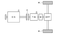
- the present invention can be applied to a single clutch type transmission similar to that described in Patent Document 1. That is, the hybrid vehicle shown in FIG. 18 has a clutch C that can cut off torque transmission between the engine E / G and the transmission T / M, and between the transmission T / M and the drive wheels W.
- the transmission T / M is an automated manual transmission.
- the present invention can also be applied to a hybrid vehicle having such a configuration, and during transmission T / M shift, the clutch C is released to cut off torque transmission from the engine E / G to the drive wheels W. . Also in this case, with respect to the torque control of the engine E / G and the motor M, the torque control at the time of shifting shown in the above-described embodiment can be used. Further, it is also possible to apply a two-system clutch at odd-numbered stages and even-numbered stages to a hybrid vehicle having a so-called dual clutch type automatic transmission.
- the output of the total torque is always shown as the total mode, but there may be a gear stage that does not output the total torque depending on the gear stage.
- the total torque before the shift is not decreased, but the torque decrease before the shift similar to the embodiment may be executed according to the difference between the torque before the shift and the compensation torque during the shift.
- the torque process at the time of shift shown in FIG. 4 is always performed.
- the present invention is not limited to this. In short, since it is desired to suppress torque loss at the time of shifting, whether or not this torque loss can occur may be added to the determination.
- this control may be executed only in a predetermined acceleration state based on a change in throttle opening. In other words, this control may not be executed at the time of an upshift in an acceleration state (including a deceleration state) below a predetermined value such as coasting.
- the supplementary torque is described based on the example in which the maximum motor torque is used.
- the present invention is not limited to this. That is, when the battery SOC exceeds a predetermined amount according to the battery SOC, the maximum motor torque is set. On the other hand, when the battery SOC is equal to or less than the predetermined amount, a value lower than the maximum motor torque is set according to the battery SOC. Good. In that case, the total pre-shift torque in the second embodiment is a value corresponding to the compensation torque.
Landscapes
- Engineering & Computer Science (AREA)
- Chemical & Material Sciences (AREA)
- Combustion & Propulsion (AREA)
- Transportation (AREA)
- Mechanical Engineering (AREA)
- Automation & Control Theory (AREA)
- Electric Propulsion And Braking For Vehicles (AREA)
- Hybrid Electric Vehicles (AREA)
Abstract
第2駆動源の最大出力を第1駆動源による最大出力よりも抑えても変速前後のトルク変動を抑えることが可能なハイブリッド車両の制御装置を提供する。 このため、自動変速機(30)の変速に際し、各係合クラッチ(37~39)のいずれかを解放してエンジン(10)から駆動輪(W)へのトルク伝達を切断した変速中に、電動モータ(20)の出力トルクを補填トルク(Tmh)として駆動輪Wに伝達する補填制御を行う駆動トルクコントローラ(50)を備え、駆動トルクコントローラ(50)は、補填制御を開始する前に、エンジン(10)、電動モータ(20)の少なくとも一方の出力トルクを、運転状態に応じた通常時の出力トルクとしての車両目標駆動トルク(tT)応じた合算トルク(Tall)から低下させる変速前出力低下制御を行うことを特徴とするハイブリッド車両の制御装置とした。
Description
本発明は、エンジン、電動モータなど動力源として2つの駆動源を備えたハイブリッド車両において、変速機の変速に伴って2つの駆動源の出力トルクの制御を行うハイブリッド車両の制御装置に関する。
従来、ハイブリッド車両において、クラッチを解放してエンジンから駆動輪へのトルク伝達を切断して変速を行う際に、電動モータから駆動輪に補填トルクを伝達するものが知られている(例えば、特許文献1参照)。
この従来技術では、クラッチを解放した状態でも駆動輪にトルク伝達可能に電動モータを設けている。そして、クラッチを解放してエンジンから駆動輪へのトルク伝達を切断した変速中に、駆動輪に対して電動モータによりトルクを補填し、エンジンと駆動輪との間のトルク伝達を切断することによるトルク抜けを抑制している。
この従来技術では、クラッチを解放した状態でも駆動輪にトルク伝達可能に電動モータを設けている。そして、クラッチを解放してエンジンから駆動輪へのトルク伝達を切断した変速中に、駆動輪に対して電動モータによりトルクを補填し、エンジンと駆動輪との間のトルク伝達を切断することによるトルク抜けを抑制している。
しかしながら、上述の従来技術では、補填トルクとして、変速前後で出力トルクに変化が生じないように変速中のエンジントルクと同等のトルクを補填しており、電動モータとしてエンジンによる出力トルクと同等の出力トルクを得ることが可能なものが必要である。この場合、装置の高コスト化、大型化を招く。
一方、電動モータを小型化してエンジン出力に対して低出力のものを用いた場合、変速前後のトルク変動が大きくなる。
一方、電動モータを小型化してエンジン出力に対して低出力のものを用いた場合、変速前後のトルク変動が大きくなる。
本発明は、上記問題に着目してなされたもので、第2駆動源の最大出力を第1駆動源による最大出力よりも抑えても変速前後のトルク変動を抑えることが可能なハイブリッド車両の制御装置を提供することを目的とする。
上記目的を達成するため、本発明は、
第1駆動源と駆動輪との動力伝達系に介在したクラッチの解放中に第1駆動源のトルク抜けを第2駆動源の出力トルクで補填する補填制御を行う制御手段を備え、
前記制御手段は、前記補填制御を開始する前に、両駆動源の少なくとも一方の出力トルクを、運転状態に応じた通常時の出力トルクから低下させる変速前出力低下制御を行うことを特徴とするハイブリッド車両の制御装置とした。
第1駆動源と駆動輪との動力伝達系に介在したクラッチの解放中に第1駆動源のトルク抜けを第2駆動源の出力トルクで補填する補填制御を行う制御手段を備え、
前記制御手段は、前記補填制御を開始する前に、両駆動源の少なくとも一方の出力トルクを、運転状態に応じた通常時の出力トルクから低下させる変速前出力低下制御を行うことを特徴とするハイブリッド車両の制御装置とした。
本発明のハイブリッド車両の制御装置では、変速時には、クラッチを解放して第1駆動源から駆動輪へのトルク伝達を切断して変速を行い、このクラッチ解放中に補填制御を行って第2駆動源による補填トルクを駆動輪に伝達する。
そして、この補填制御を開始する前に、両駆動源の少なくとも一方の出力トルクを、運転状態に応じた通常時の出力トルクから低下させる変速前出力低下制御を行う。
このため、第2駆動源の最大出力が第1駆動源による最大出力よりも低くても、変速前出力低下制御を行わないものと比較して、変速前後のトルク変動を抑えることが可能となる。
そして、この補填制御を開始する前に、両駆動源の少なくとも一方の出力トルクを、運転状態に応じた通常時の出力トルクから低下させる変速前出力低下制御を行う。
このため、第2駆動源の最大出力が第1駆動源による最大出力よりも低くても、変速前出力低下制御を行わないものと比較して、変速前後のトルク変動を抑えることが可能となる。
以下、本発明のハイブリッド車両の制御装置を実現する最良の形態を、図面に示す実施の形態に基づいて説明する。
(実施の形態1)
図1は、実施の形態1のハイブリッド車両の制御装置およびその駆動系の概略構造を示す全体図である。
前記ハイブリッド車両は、駆動源として第1駆動源に相当するエンジン10と、第2駆動源に相当する電動モータ20と、を備えている。
そして、エンジン10と駆動輪Wとの駆動伝達経路に、自動変速機30が介在されている。
(実施の形態1)
図1は、実施の形態1のハイブリッド車両の制御装置およびその駆動系の概略構造を示す全体図である。
前記ハイブリッド車両は、駆動源として第1駆動源に相当するエンジン10と、第2駆動源に相当する電動モータ20と、を備えている。
そして、エンジン10と駆動輪Wとの駆動伝達経路に、自動変速機30が介在されている。
自動変速機30は、エンジン10が接続された主入力軸31と、駆動輪Wにトルクを出力する主出力軸32と、を備えている。また、主入力軸31には、主入力軸31に対して空走回転可能な第1副入力軸31aおよび第2副入力軸31bが、主入力軸31に並列に設けられている。同様に、主出力軸32にも、主出力軸32に対して空走回転可能な第1副出力軸32a、第2副出力軸32b、第3副出力軸32cが、主出力軸32に並列に設けられている。
そして、各入力軸31,31a,31bと各出力軸32,32a,32b,32cとの間に、変速比の異なる複数のドライブギヤ組33,34,35,36が設けられている。
そして、各入力軸31,31a,31bと各出力軸32,32a,32b,32cとの間に、変速比の異なる複数のドライブギヤ組33,34,35,36が設けられている。
さらに、自動変速機30の主入力軸31、主出力軸32には、第1係合クラッチ37、第2係合クラッチ38、第3係合クラッチ39が設けられている。各係合クラッチ37~39は、本実施の形態1では、シンクロ機構を持たないドグクラッチを用いており、ハブが軸方向の3位置に移動して係合状態を切り替える。すなわち、ハブを3位置の中央位置では、ハブは、隣り合う各副入力軸31a,31b、各副出力軸32a~32c、ケースに、それぞれ設けられたスプラインのいずれとも係合せず、トルク伝達が切断されたニュートラル状態となる。そして、このニュートラル状態から軸方向の正逆のいずれかの方向(図において左右方向)に移動すると、ハブは、各副入力軸31a,31b、各副出力軸32a~32c、ケースに、それぞれ設けられたスプラインのいずれかと係合してトルク伝達を行う。
なお、自動変速機30の変速時には、各係合クラッチ37~39のいずれかを解放して、エンジン10の駆動力が主出力軸32から駆動輪Wへ伝達されない状態として、解放から締結へ切り替えるクラッチの入出力回転同期させて締結し変速を行う。
なお、自動変速機30の変速時には、各係合クラッチ37~39のいずれかを解放して、エンジン10の駆動力が主出力軸32から駆動輪Wへ伝達されない状態として、解放から締結へ切り替えるクラッチの入出力回転同期させて締結し変速を行う。
各係合クラッチ37~39の係合状態の切り替えは、それぞれ、アクチュエータ37a,38a,39aによりハブを移動させることにより行われる。これらのアクチュエータ37a,38a,39aは、油圧あるいは電動により駆動するもので、その駆動は変速コントローラ40により制御される。なお、変速コントローラ40は、マイクロコンピュータを備えた電子制御ユニット(ECU)により構成されている。
また、自動変速機30は、各クラッチ37~39による切り替えに基づいて形成される駆動輪Wへのトルク伝達モードとして、トルク合算モードとトルク補填モードとを形成可能となっている。
トルク合算モードは、エンジン10と電動モータ20との出力トルクを合算して駆動輪Wに伝達可能なモードである。
このトルク合算モードは、例えば、図2に示すように、第1係合クラッチ37および第3係合クラッチ39を図において右方向に係合させて形成することができる。この場合、図において実線により示すエンジン10の出力トルクであるエンジントルクTeと、図において点線により示す電動モータ20の出力トルクであるモータトルクTmを合算して、主出力軸32から駆動輪Wへ出力可能である。なお、トルク合算モードでは、電動モータ20の出力トルクを0とすれば、エンジントルクTeのみを駆動輪Wへ出力可能である。
トルク合算モードは、エンジン10と電動モータ20との出力トルクを合算して駆動輪Wに伝達可能なモードである。
このトルク合算モードは、例えば、図2に示すように、第1係合クラッチ37および第3係合クラッチ39を図において右方向に係合させて形成することができる。この場合、図において実線により示すエンジン10の出力トルクであるエンジントルクTeと、図において点線により示す電動モータ20の出力トルクであるモータトルクTmを合算して、主出力軸32から駆動輪Wへ出力可能である。なお、トルク合算モードでは、電動モータ20の出力トルクを0とすれば、エンジントルクTeのみを駆動輪Wへ出力可能である。
トルク補填モードは、各係合クラッチ37~39のいずれかを解放してエンジントルクTeが主出力軸32に伝達されない状態とし、このクラッチ解放中に、モータトルクTmを、主出力軸32を介して駆動輪Wに伝達するモードである。例えば、図2に示す両係合クラッチ37,39の係合状態から第1係合クラッチ37をニュートラル状態に切り替えることで形成することができる。
このように、電動モータ20のモータトルクTmは、エンジン10のトルク伝達を遮断するクラッチの解放時、締結時のいずれの場合でも、駆動輪Wへ伝達可能となっている。
このように、電動モータ20のモータトルクTmは、エンジン10のトルク伝達を遮断するクラッチの解放時、締結時のいずれの場合でも、駆動輪Wへ伝達可能となっている。
上記のトルク伝達モードの切り替えは、変速コントローラ40により変速制御に伴って成される。
なお、変速コントローラ40により実行される変速制御は、周知の制御であり、車速センサ61が検出する車速VSPと、スロットル開度センサ62が検出するスロットル開度APOとに基づいて、予め設定された変速マップにより変速段を決定する。なお、図3に変速マップの一例を示す。
なお、変速コントローラ40により実行される変速制御は、周知の制御であり、車速センサ61が検出する車速VSPと、スロットル開度センサ62が検出するスロットル開度APOとに基づいて、予め設定された変速マップにより変速段を決定する。なお、図3に変速マップの一例を示す。
駆動トルクコントローラ50は、エンジン10および電動モータ20の出力トルクを制御する。この出力トルクの制御において、通常の走行時(非変速時)は、運転状態に応じた通常時の出力トルクとしての車両目標駆動トルクtTが得られるように、エンジン10および電動モータ20の出力トルクを制御する。
ここで、車両目標駆動トルクtTは、周知のように、スロットル開度APOと車速VSPとに基づいて、予め設定された目標駆動トルクマップに基づいて算出する。図5に、車両目標駆動トルクマップの一例を示しており、車両目標駆動トルクは、相対的に高車速では低車速に比べて低く設定し、かつ、相対的に小スロットル開度では大スロットル開度に比べて低く設定する。
なお、駆動トルクコントローラ50は、マイクロコンピュータを備えた電子制御ユニット(ECU)により構成されている。また、車速センサ61およびスロットル開度センサ62を含むセンサ群60からの信号は、各コントローラ40,50に直接、あるいは、図示を省略したCAN通信線などを介して間接的に入力される。
ここで、車両目標駆動トルクtTは、周知のように、スロットル開度APOと車速VSPとに基づいて、予め設定された目標駆動トルクマップに基づいて算出する。図5に、車両目標駆動トルクマップの一例を示しており、車両目標駆動トルクは、相対的に高車速では低車速に比べて低く設定し、かつ、相対的に小スロットル開度では大スロットル開度に比べて低く設定する。
なお、駆動トルクコントローラ50は、マイクロコンピュータを備えた電子制御ユニット(ECU)により構成されている。また、車速センサ61およびスロットル開度センサ62を含むセンサ群60からの信号は、各コントローラ40,50に直接、あるいは、図示を省略したCAN通信線などを介して間接的に入力される。
また、駆動トルクコントローラ50は、変速に伴い、後述する補填制御および変速前出力低下制御を含む変速時トルク制御を実行する。
図4は、駆動トルクコントローラ50による変速時トルク制御の処理の流れを示すフローチャートである。
このフローチャートに示す変速時トルク制御は、変速コントローラ40がアップシフト変速を行うことを決定することにより開始されるもので、アップシフト変速を行う前の変速前合算トルクとクラッチ解放中の補填トルクとを演算して出力する処理である。
図4は、駆動トルクコントローラ50による変速時トルク制御の処理の流れを示すフローチャートである。
このフローチャートに示す変速時トルク制御は、変速コントローラ40がアップシフト変速を行うことを決定することにより開始されるもので、アップシフト変速を行う前の変速前合算トルクとクラッチ解放中の補填トルクとを演算して出力する処理である。
なお、アップシフト変速は、車速VSPおよびスロットル開度APOにより決定される動作点が、図3において点線により示す変速線を左から右に横切ることにより決定される。ここで、本実施の形態1では、変速時に補填制御を開始する前に、後述する運転状態に応じて通常時の出力トルクに相当する変速前合算トルクを低下させる変速前出力低下制御を行う。このため、本実施の形態1における、変速時トルク制御を開始するための上記の変速決定タイミングは、変速前出力低下制御を実行しない従来からの変速決定タイミングよりも早いタイミングとなるように変速線を設定している。あるいは、通常用いる変速線による変速決定タイミングよりも、変速前合算トルクの出力を行う時間だけ、早いタイミングで、変速実行を予測したことにより変速時トルク制御を開始するようにしてもよい。
以下、変速時トルク処理について説明する。
変速決定後に最初に進むステップS1では、変速中か否か判定し、自動変速機30において変速を行っている変速中はステップS2に進み、変速中でない場合、すなわち、変速前はステップS3に進む。なお、変速中とは、自動変速機30において、各係合クラッチ37~39のいずれか1つまたは2つを解放(ニュートラル状態)してエンジン10の出力トルクが駆動輪Wに伝達されない状態として、変速前の変速段から変速後の変速段に切り替えるまでの間をいう。この変速中であって各係合クラッチ37~39においてトルク伝達切断のためのクラッチ解放中に、自動変速機30では、解放中のクラッチとは異なるクラッチの架け替えを行う。
変速決定後に最初に進むステップS1では、変速中か否か判定し、自動変速機30において変速を行っている変速中はステップS2に進み、変速中でない場合、すなわち、変速前はステップS3に進む。なお、変速中とは、自動変速機30において、各係合クラッチ37~39のいずれか1つまたは2つを解放(ニュートラル状態)してエンジン10の出力トルクが駆動輪Wに伝達されない状態として、変速前の変速段から変速後の変速段に切り替えるまでの間をいう。この変速中であって各係合クラッチ37~39においてトルク伝達切断のためのクラッチ解放中に、自動変速機30では、解放中のクラッチとは異なるクラッチの架け替えを行う。
変速中に進むステップS2では、エンジントルクTeを0とするとともに、モータトルクTmを、予め設定された補填トルクTmhとする補填制御を実行する。なお、本実施の形態1では、補填トルクTmhは、電動モータ20の最大トルクとしている。
すなわち、本実施の形態1では、エンジントルクTeが駆動輪Wに伝達されない変速中(クラッチ解放中)に、電動モータ20から駆動輪Wに補填トルクTmhを伝達して、変速中のトルク抜けを抑制している。
すなわち、本実施の形態1では、エンジントルクTeが駆動輪Wに伝達されない変速中(クラッチ解放中)に、電動モータ20から駆動輪Wに補填トルクTmhを伝達して、変速中のトルク抜けを抑制している。
ステップS1において、変速中でない場合、すなわち、変速前であって補填制御の開始前に進むステップS3では、車両目標駆動トルクtTを算出するかあるいは読み込み、次のステップS4に進む。なお、この車両目標駆動トルクtTは、前述のように、スロットル開度APOと車速VSPとに基づいて、予め設定された目標駆動トルクマップに基づいて算出する。
ステップS3に続くステップS4では、変速前の合算トルク低下量Tteiを算出した後、ステップS5に進む。
すなわち、本実施の形態1では、走行中は、エンジントルクTeとモータトルクTmとを合算した合算トルクTallが、車両目標駆動トルクtTとなるように、エンジン10と電動モータ20との出力トルクを制御している。
すなわち、本実施の形態1では、走行中は、エンジントルクTeとモータトルクTmとを合算した合算トルクTallが、車両目標駆動トルクtTとなるように、エンジン10と電動モータ20との出力トルクを制御している。
それに対して、本実施の形態1では、補填制御を開始する前に、運転状態に応じた合算トルクTallを低下させる変速前出力低下制御を実行することにより、変速前後のトルク変化を抑制している。そして、本実施の形態1では、この変速前の合算トルク低下量Tteiは、図7、図9に示すように、変速前合算トルクTabeを、車両目標駆動トルクtTよりも低い変速後合算トルクTaafに一致させるように設定している。
合算トルク低下量Tteiを算出したステップS4に続くステップS5では、変速前モータトルクTmbeを、図6に示す変速前モータトルクマップに基づいて算出し、次のステップS6に進む。また、ステップS6では、変速前モータトルクに基づいて、合算トルク低下量Tteiを達成するための変速前エンジントルクTebeを算出する。
すなわち、合算トルク低下量Tteiを達成するには、モータトルクTmとエンジントルクTeとの、いずれか一方、あるいは両方を低下させて達成することができる。そこで、本実施の形態1では、まず、バッテリSOCに基づいてモータトルクTmの低下量を決定し、このモータトルクTmの低下量による合算トルク低下量Tteiの不足分だけ、エンジントルクTeを低下させるようにしている。なお、バッテリSOCは、図外のバッテリの充電量に相当する値である。
ここで、図6の変速前モータトルクマップに示す変速前モータトルクTmbeは、バッテリSOCが高設定値SOChiよりも高い場合には、最大モータトルクTmmaxとする。一方、バッテリSOCが、補填トルクTmhの出力を補償する低設定値SOCloよりも低い場合には、変速前モータトルクTmbeを0とする。そして、バッテリSOCが、低設定値SOCloと高設定値SOChiとの間では、バッテリSOCに応じて、変速前モータトルクTmbeを、0と最大モータトルクTmmaxとの間で、バッテリSOCが高くなるほど大きく設定する。
なお、ステップS5,S6において算出された変速前モータトルクTmbe、変速前エンジントルクTebeに基づいてモータトルクTmおよびエンジントルクTeが制御される。
なお、ステップS5,S6において算出された変速前モータトルクTmbe、変速前エンジントルクTebeに基づいてモータトルクTmおよびエンジントルクTeが制御される。
(実施の形態1の作用)
実施の形態1の作用を説明する前に、変速前合算トルクを低下させる変速前出力低下制御を実行しない比較例の動作例を図11、図12に基づいて説明する。
図11は、変速前後では、エンジントルクTeのみを運転状態に応じた通常時の出力トルク(車両目標駆動トルクtT)として駆動輪に伝達し、変速中は、モータトルクTmのみを補填トルクTmhとして駆動輪に伝達するようにした動作例を示している。
実施の形態1の作用を説明する前に、変速前合算トルクを低下させる変速前出力低下制御を実行しない比較例の動作例を図11、図12に基づいて説明する。
図11は、変速前後では、エンジントルクTeのみを運転状態に応じた通常時の出力トルク(車両目標駆動トルクtT)として駆動輪に伝達し、変速中は、モータトルクTmのみを補填トルクTmhとして駆動輪に伝達するようにした動作例を示している。
この図11では、縦軸に車両トルクを、横軸に車速をとって、加速によるシフトアップ変速時の車速上昇に伴うトルク変化を示している。
この場合、変速前後で、エンジントルクTeのみで加速を行うため、エンジントルクTeにモータトルクTmを合算した車両トルクにより加速を行うものと比較して、加速性に劣る。
また、変速前後のトルク変動を抑えるには、補填トルク(モータトルク)Tmhを大きくするのが好ましいが、その場合、電動モータとして相対的に大型のものが必要となり、コスト増、重量増を招く。しかも、補填トルクの出力のためだけに大型の電動モータを設けるのは、不経済である。
この場合、変速前後で、エンジントルクTeのみで加速を行うため、エンジントルクTeにモータトルクTmを合算した車両トルクにより加速を行うものと比較して、加速性に劣る。
また、変速前後のトルク変動を抑えるには、補填トルク(モータトルク)Tmhを大きくするのが好ましいが、その場合、電動モータとして相対的に大型のものが必要となり、コスト増、重量増を招く。しかも、補填トルクの出力のためだけに大型の電動モータを設けるのは、不経済である。
一方、図12は、変速前後で、エンジントルクTeとモータトルクTmとの合算トルクにより要求トルクに応じた出力トルクを得るようにした例であり、この場合、図11に示したものよりも、加速性に優れる。しかしながら、補填制御の開始前からモータトルクTmを上乗せしているため、仮にモータとして大トルクのものを用いたとしても、変速前と変速中とでは、エンジントルクTe分だけ差が生じ、変速時のトルク変動が大きくなる。
以上のように、図11、図12に示す比較例では、モータトルクTmを無駄にすることなく加速にも使用して高い加速性能を確保しつつ、変速前後のトルク変動を抑えることは難しい。
以上のように、図11、図12に示す比較例では、モータトルクTmを無駄にすることなく加速にも使用して高い加速性能を確保しつつ、変速前後のトルク変動を抑えることは難しい。
次に、図7~図10に基づいて、車両の加速に伴って、シフトアップ変速する際の本実施の形態1におけるトルク伝達状態および駆動輪Wに伝達されるトルク(車両トルク)の変化について説明する。なお、図7、図8は、バッテリSOCが相対的に少ない場合の動作例であり、図9、図10は、バッテリSOCが相対的に多い場合の動作例である。
まず、図7に基づいて説明する。
図7に示す動作例では、車速VSPが上昇するのに伴って、第1の変速段から第2の変速段にシフトアップ変速を行っており、図において変速開始時車速VSP72と変速終了時車速VSP73との間で、自動変速機30の変速を行っている。この変速開始時車速VSP72から変速終了時車速VSP73までが、各係合クラッチ37~39のいずれかの解放中(変速中)であり、エンジン10と駆動輪Wとの駆動伝達を切断する。
図7に示す動作例では、車速VSPが上昇するのに伴って、第1の変速段から第2の変速段にシフトアップ変速を行っており、図において変速開始時車速VSP72と変速終了時車速VSP73との間で、自動変速機30の変速を行っている。この変速開始時車速VSP72から変速終了時車速VSP73までが、各係合クラッチ37~39のいずれかの解放中(変速中)であり、エンジン10と駆動輪Wとの駆動伝達を切断する。
この場合、変速開始時車速VSP72よりも低車速側(変速前の第1の変速段)と変速終了時車速VSP73よりも高車速側(変速後の第2の変速段)とで、エンジントルクTeとモータトルクTmとの両トルクを合算した合算トルクTallを出力している。したがって、エンジントルクTeのみの出力と比較して、高い加速性能を得ることができる。なお、この第1の変速段は、例えば、図2に一例を示したように、第1係合クラッチ37および第3係合クラッチ39を右方向に係合させ、第2係合クラッチ38をニュートラル状態とすることで形成することができる。また、第2の変速段は、第1の変速段から、第1係合クラッチ37をニュートラル状態とし、第2係合クラッチ38を図において右方向に係合させることで形成することができる。
両変速段における合算トルクTallは、車両目標駆動トルクtTに一致するように出力しており、図7の例では、モータトルクTmとして、最大モータトルクTmmaxを出力し、モータトルクTmを効率的に加速に用いている。
両変速段における合算トルクTallは、車両目標駆動トルクtTに一致するように出力しており、図7の例では、モータトルクTmとして、最大モータトルクTmmaxを出力し、モータトルクTmを効率的に加速に用いている。
一方、変速開始時車速VSP72~変速終了時車速VSP73の間の変速中は、ステップS1→S2の処理の流れに基づいて、モータトルクTmによる補填トルクTmhを出力する補填制御を実行する。この場合、図2により示したように、第1係合クラッチ37はニュートラル状態とし、第3係合クラッチ39を右側に係合させた状態とし、自動変速機30をトルク補填モードとする。これにより、駆動輪Wに対してエンジントルクTeの伝達を断って変速を行いながら、駆動輪WへモータトルクTmを伝達する。
上述のような変速時の駆動トルク制御において、本実施の形態1では、変速を決定してから補填制御を開始する前に、駆動輪Wに伝達する合算トルクTallを、通常時の出力トルクである車両目標駆動トルクtTに応じた合算トルクTallから低下させる変速前出力低下制御を行う。
この変速前出力低下制御により、図7の変速を決定したときの車速である変速決定時車速VSP71から変速を開始する変速開始時車速VSP72の間で、合算トルクTallを車両目標駆動トルク(通常時の出力トルク)tTよりも低下させる。
この際の合算トルク低下量Tteiは、図4のステップS4の演算に基づくものである。そして、本実施の形態1では、図7に示すように変速開始時車速VSP72の合算トルクTallである変速前合算トルクTabeが、変速後の合算トルクTallである変速後合算トルクTaafに一致するよう、合算トルク低下量Tteiを算出する。
この際の合算トルク低下量Tteiは、図4のステップS4の演算に基づくものである。そして、本実施の形態1では、図7に示すように変速開始時車速VSP72の合算トルクTallである変速前合算トルクTabeが、変速後の合算トルクTallである変速後合算トルクTaafに一致するよう、合算トルク低下量Tteiを算出する。
この合算トルク低下量Tteiは、モータトルクTmとエンジントルクTeのいずれか一方あるいは両方を低減することで達成できるが、図7に示す例では、モータトルクTmを0まで低下させ、さらに、エンジントルクTeを低下させている。
すなわち、図4のステップS5の処理に基づいて、バッテリSOCが、低設定値SOCloよりも低い場合、電力を温存するため、図6に示すように、変速前モータトルクTmbeは、0に設定する。したがって、続くステップS6では、変速前モータトルクTmbeを0とした上で変速前合算トルクTabeを得ることができる変速前エンジントルクTebeを決定する。
すなわち、図4のステップS5の処理に基づいて、バッテリSOCが、低設定値SOCloよりも低い場合、電力を温存するため、図6に示すように、変速前モータトルクTmbeは、0に設定する。したがって、続くステップS6では、変速前モータトルクTmbeを0とした上で変速前合算トルクTabeを得ることができる変速前エンジントルクTebeを決定する。
図8は、図7の動作時の各トルク出力状態を示すタイムチャートである。この図に示すように、車両目標駆動トルク(通常時の出力トルク)tTに応じた合算トルクTallから変速前合算トルクTabeに低下させるのにあたり、t81の時点からモータトルクTmを低下させ、さらに、t82の時点からエンジントルクTeを低下させる。
そして、変速中であって補填制御実行中であるt83~t84の時点では、エンジントルクTe=0にする一方で、モータトルクTmを用いた補填トルクTmhを駆動輪Wに伝達し、変速中のエンジントルク伝達の切断によるトルク抜けを抑えている。この補填トルクTmhは、電動モータ20の最大トルクである最大モータトルクTmmaxとする。
その後、変速終了時点(t84)からエンジントルクTeを車両目標駆動トルクtTに応じて立ち上げて、合算トルクTall=tTとしており、この合算トルクTallを得るためにモータトルクTmは、最大モータトルクTmmaxに維持している。
以上の処理に基づいて、本実施の形態1では、変速前、変速中、変速後の車両トルク変化を抑えることができる。
また、変速前後の合算トルクTallには、最大モータトルクTmmaxを加算して、高い加速性能を得ることができる。
また、変速前後の合算トルクTallには、最大モータトルクTmmaxを加算して、高い加速性能を得ることができる。
次に、図9、図10の動作について説明する。
前述のように、図9、図10は、バッテリSOCが十分に確保されている場合の動作である。この場合、図10に示すように、モータトルクTmは、変速前、変速中、変速後に亘って最大モータトルクTmmaxに保持したままとする。
したがって、電動モータ20の駆動力を有効に利用することができる。
この場合、変速前合算トルクTabeは、エンジントルクTeを合算トルク低下量Tteiだけ低下させることにより達成する。なお、図9において、図7の動作例と同様に、変速決定時車速VSP71から変速前合算トルクTabeを低下させ、変速開始時車速VSP72において変速前合算トルクTabeを、変速後合算トルクTaafに一致させる変速前出力低下制御を実行する。
この場合、制御対象がエンジントルクTeのみであり、制御が容易となる。
前述のように、図9、図10は、バッテリSOCが十分に確保されている場合の動作である。この場合、図10に示すように、モータトルクTmは、変速前、変速中、変速後に亘って最大モータトルクTmmaxに保持したままとする。
したがって、電動モータ20の駆動力を有効に利用することができる。
この場合、変速前合算トルクTabeは、エンジントルクTeを合算トルク低下量Tteiだけ低下させることにより達成する。なお、図9において、図7の動作例と同様に、変速決定時車速VSP71から変速前合算トルクTabeを低下させ、変速開始時車速VSP72において変速前合算トルクTabeを、変速後合算トルクTaafに一致させる変速前出力低下制御を実行する。
この場合、制御対象がエンジントルクTeのみであり、制御が容易となる。
(実施の形態1の効果)
以下に、実施の形態1のハイブリッド車両の制御装置の効果を列挙する。
1)実施の形態1のハイブリッド車両の制御装置は
第1駆動源としてのエンジン10と駆動輪Wとの駆動伝達系に介在された自動変速機30と、
前記エンジン10と駆動輪Wとの動力伝達系に介在され、前記自動変速機30の変速中に解放するクラッチとしての第1係合クラッチ37~第3係合クラッチ39と、
前記第1係合クラッチ37~第3係合クラッチ39のいずれかの解放中に前記駆動輪Wへトルク伝達可能に設けられた第2駆動源としての電動モータ20と、
前記クラッチの解放中に前記エンジン10のトルク抜けを前記電動モータ20の出力トルクで補填する補填制御を行う制御手段としての駆動トルクコントローラ50と、
を備え、
前記駆動トルクコントローラ50は、前記補填制御を開始する前に、エンジン10と電動モータ20との少なくとも一方の出力トルクを、運転状態に応じた通常時の出力トルク(車両目標駆動トルクtT)から低下させる変速前出力低下制御を行うことを特徴とする。
したがって、電動モータ20の最大モータトルクTmmaxがエンジン10の最大出力よりも低い場合であっても、変速前出力低下制御を行わないものと比較して、補填制御前と補填制御時とのトルク変動を抑えることが可能となる。
以下に、実施の形態1のハイブリッド車両の制御装置の効果を列挙する。
1)実施の形態1のハイブリッド車両の制御装置は
第1駆動源としてのエンジン10と駆動輪Wとの駆動伝達系に介在された自動変速機30と、
前記エンジン10と駆動輪Wとの動力伝達系に介在され、前記自動変速機30の変速中に解放するクラッチとしての第1係合クラッチ37~第3係合クラッチ39と、
前記第1係合クラッチ37~第3係合クラッチ39のいずれかの解放中に前記駆動輪Wへトルク伝達可能に設けられた第2駆動源としての電動モータ20と、
前記クラッチの解放中に前記エンジン10のトルク抜けを前記電動モータ20の出力トルクで補填する補填制御を行う制御手段としての駆動トルクコントローラ50と、
を備え、
前記駆動トルクコントローラ50は、前記補填制御を開始する前に、エンジン10と電動モータ20との少なくとも一方の出力トルクを、運転状態に応じた通常時の出力トルク(車両目標駆動トルクtT)から低下させる変速前出力低下制御を行うことを特徴とする。
したがって、電動モータ20の最大モータトルクTmmaxがエンジン10の最大出力よりも低い場合であっても、変速前出力低下制御を行わないものと比較して、補填制御前と補填制御時とのトルク変動を抑えることが可能となる。
2)実施の形態1のハイブリッド車両の制御装置は、
前記第2駆動源は、電力により駆動する電動モータ20であり、
前記駆動トルクコントローラ50は、前記補填制御を開始する前に、前記エンジン10の出力トルクであるエンジントルクTeと前記電動モータ20の出力トルクであるモータトルクTmとを合わせた合算トルクTallを出力している場合に、前記変速前出力低下制御時の前記第1駆動源としてのエンジントルク低下量とモータトルク低下量との割合をバッテリSOCに基づいて決定することを特徴とする。
したがって、バッテリSOCが低下した場合は、モータトルクTmを低下させることにより、バッテリ充電量を温存可能である。
一方、バッテリSOCが確保されている場合は、モータトルクTmの低下を抑制してバッテリ電力の有効利用を図りつつ、エンジントルクTeの低下により変速前に合算トルクTallを低下させて、変速前、変速中、変速後のトルク変動を抑えることができる。
加えて、車両目標駆動トルクtTを得るのにあたり合算トルクTallを出力するようにしたため、モータトルクTmを無駄にすることなく有効利用でき、エンジントルクTeのみで加速を行うよりも、加速性能を向上させることが可能である。そして、このように合算トルクTallを出力して加速性能を確保したものにおいて、変速前出力低下処理を行うことで、上記1)の変速前後のトルク変動を抑えることができる効果が得られる。
すなわち、補填制御開始前に合算トルクTallを出力する場合、変速前にエンジントルクTeのみの出力するものと比較して、補填制御開始前の出力トルクと補填トルクTmhとの差がより大きくなるが、この差によるトルク変動を抑えることができる。
前記第2駆動源は、電力により駆動する電動モータ20であり、
前記駆動トルクコントローラ50は、前記補填制御を開始する前に、前記エンジン10の出力トルクであるエンジントルクTeと前記電動モータ20の出力トルクであるモータトルクTmとを合わせた合算トルクTallを出力している場合に、前記変速前出力低下制御時の前記第1駆動源としてのエンジントルク低下量とモータトルク低下量との割合をバッテリSOCに基づいて決定することを特徴とする。
したがって、バッテリSOCが低下した場合は、モータトルクTmを低下させることにより、バッテリ充電量を温存可能である。
一方、バッテリSOCが確保されている場合は、モータトルクTmの低下を抑制してバッテリ電力の有効利用を図りつつ、エンジントルクTeの低下により変速前に合算トルクTallを低下させて、変速前、変速中、変速後のトルク変動を抑えることができる。
加えて、車両目標駆動トルクtTを得るのにあたり合算トルクTallを出力するようにしたため、モータトルクTmを無駄にすることなく有効利用でき、エンジントルクTeのみで加速を行うよりも、加速性能を向上させることが可能である。そして、このように合算トルクTallを出力して加速性能を確保したものにおいて、変速前出力低下処理を行うことで、上記1)の変速前後のトルク変動を抑えることができる効果が得られる。
すなわち、補填制御開始前に合算トルクTallを出力する場合、変速前にエンジントルクTeのみの出力するものと比較して、補填制御開始前の出力トルクと補填トルクTmhとの差がより大きくなるが、この差によるトルク変動を抑えることができる。
3)実施の形態1のハイブリッド車両の制御装置は、
駆動トルクコントローラ50は、前記変速前出力低下制御による出力トルクの低下時に、変速後の出力トルクである変速後合算トルクTaafまで低下させることを特徴とする。
したがって、変速前と変速後とでトルク段差が生じるのを抑えることができる。
駆動トルクコントローラ50は、前記変速前出力低下制御による出力トルクの低下時に、変速後の出力トルクである変速後合算トルクTaafまで低下させることを特徴とする。
したがって、変速前と変速後とでトルク段差が生じるのを抑えることができる。
4)実施の形態1のハイブリッド車両の制御装置は、
前記合算トルクTallは、前記運転状態に応じた通常時の出力トルクを車両目標駆動トルクtTに基づいて決定し、
駆動トルクコントローラ50は、前記変速前出力低下制御時による合算トルクTallの低下時の変速前合算トルクTabeは、車両目標駆動トルクtTよりも低下させることを特徴とする。
したがって、合算トルクTallを車両目標駆動トルクtTに基づいて決定することで、確実な加速性能を得ることができる。また、変速前合算トルクTabeを車両目標駆動トルクtTに基づく通常時の出力トルクよりも低下させることにより、確実に合算トルクTallを低下させることができる。
前記合算トルクTallは、前記運転状態に応じた通常時の出力トルクを車両目標駆動トルクtTに基づいて決定し、
駆動トルクコントローラ50は、前記変速前出力低下制御時による合算トルクTallの低下時の変速前合算トルクTabeは、車両目標駆動トルクtTよりも低下させることを特徴とする。
したがって、合算トルクTallを車両目標駆動トルクtTに基づいて決定することで、確実な加速性能を得ることができる。また、変速前合算トルクTabeを車両目標駆動トルクtTに基づく通常時の出力トルクよりも低下させることにより、確実に合算トルクTallを低下させることができる。
5)実施の形態1のハイブリッド車両の制御装置は、
エンジン10から駆動輪Wへのトルク伝達を切断可能なクラッチは、自動変速機30に設けられて、変速段の切り替え時にトルク伝達を行うギヤの架け替えを行う噛合クラッチとしての各係合クラッチ37~39であることを特徴とする。
すなわち、自動変速機30では、シンクロ機構を有しない各係合クラッチ37~39の架け替えを行う場合、エンジン10から駆動輪Wへのトルク伝達を完全に遮断する必要が生じるとともに、トルク伝達を切断する時間も、シンクロ機構を有したものと比較して長くなる。
したがって、上記1)~4)のように、変速中(クラッチ解放中)に、補填トルクTmhを駆動輪Wに伝達して、トルク抜けを抑制することが、より有効であり重要となる。
エンジン10から駆動輪Wへのトルク伝達を切断可能なクラッチは、自動変速機30に設けられて、変速段の切り替え時にトルク伝達を行うギヤの架け替えを行う噛合クラッチとしての各係合クラッチ37~39であることを特徴とする。
すなわち、自動変速機30では、シンクロ機構を有しない各係合クラッチ37~39の架け替えを行う場合、エンジン10から駆動輪Wへのトルク伝達を完全に遮断する必要が生じるとともに、トルク伝達を切断する時間も、シンクロ機構を有したものと比較して長くなる。
したがって、上記1)~4)のように、変速中(クラッチ解放中)に、補填トルクTmhを駆動輪Wに伝達して、トルク抜けを抑制することが、より有効であり重要となる。
(他の実施の形態)
次に、他の実施の形態のハイブリッド車両の制御装置について説明する。
なお、他の実施の形態を説明するのにあたり、実施の形態1と共通する構成には実施の形態1と同じ符号を付して説明を省略し、実施の形態1との相違点のみ説明する。
次に、他の実施の形態のハイブリッド車両の制御装置について説明する。
なお、他の実施の形態を説明するのにあたり、実施の形態1と共通する構成には実施の形態1と同じ符号を付して説明を省略し、実施の形態1との相違点のみ説明する。
(実施の形態2)
実施の形態2のハイブリッド車両の制御装置は、実施の形態1の変形例であり、ステップS4における合算トルクTallの低下量、すなわち、変速前合算トルクTabeの求め方が実施の形態1と異なる。
実施の形態2では、変速前出力低下制御時の変速前合算トルクTabeを、図13に示すように、補填トルクTmh、すなわち、最大モータトルクTmmaxと等しくなるまで低下させるようにした例である。この実施の形態2にあっても、実施の形態1と同様に、変速前合算トルクTabeを得るための低下量は、まず、変速前モータトルクTmbeを演算し(ステップS5)、その後、変速前エンジントルクTebeを算出する。また、この場合、バッテリSOCに応じて、各低下量を演算する。
したがって、実施の形態2では、変速前の補填制御開始前とクラッチ解放中の補填制御中とでトルク変化がなくなり、変速時のトルク変動を、より抑えることが可能となる。
実施の形態2のハイブリッド車両の制御装置は、実施の形態1の変形例であり、ステップS4における合算トルクTallの低下量、すなわち、変速前合算トルクTabeの求め方が実施の形態1と異なる。
実施の形態2では、変速前出力低下制御時の変速前合算トルクTabeを、図13に示すように、補填トルクTmh、すなわち、最大モータトルクTmmaxと等しくなるまで低下させるようにした例である。この実施の形態2にあっても、実施の形態1と同様に、変速前合算トルクTabeを得るための低下量は、まず、変速前モータトルクTmbeを演算し(ステップS5)、その後、変速前エンジントルクTebeを算出する。また、この場合、バッテリSOCに応じて、各低下量を演算する。
したがって、実施の形態2では、変速前の補填制御開始前とクラッチ解放中の補填制御中とでトルク変化がなくなり、変速時のトルク変動を、より抑えることが可能となる。
以上説明した実施の形態2のハイブリッド車両の制御装置は、上述した1)2)4)5)の効果に加え、下記2-1)の効果を奏する。
2-1)実施の形態2のハイブリッド車両の制御装置は、
駆動トルクコントローラ50は、変速前出力低下制御時に、変速前合算トルクTabeを、電動モータ20により補填可能な駆動トルクである補填トルクTmhであって、最大モータトルクTmmaxまで低下させることを特徴とする。
したがって、上記のように変速前と変速中とでトルク変化がなくなり、変速時のトルク変動を抑えることが可能となる。なお、補填トルクTmhが、最大モータトルクTmmaxよりも低い場合には、変速前出力低下制御時に、この補填トルクTmhに一致するまで低下させる。
2-1)実施の形態2のハイブリッド車両の制御装置は、
駆動トルクコントローラ50は、変速前出力低下制御時に、変速前合算トルクTabeを、電動モータ20により補填可能な駆動トルクである補填トルクTmhであって、最大モータトルクTmmaxまで低下させることを特徴とする。
したがって、上記のように変速前と変速中とでトルク変化がなくなり、変速時のトルク変動を抑えることが可能となる。なお、補填トルクTmhが、最大モータトルクTmmaxよりも低い場合には、変速前出力低下制御時に、この補填トルクTmhに一致するまで低下させる。
(実施の形態3)
実施の形態3のハイブリッド車両の制御装置は、変速前出力低下制御時の合算トルクTallの低減を、モータトルクTmの出力低下のみにより行うようにした例である。
図14に示すように、実施の形態3では、変速前出力低下制御時には、常に、合算トルクTallの低減を、モータトルクTmの出力低下のみにより行うようにし、加えて、この際にモータトルクTmを0まで低下させるようにしている。すなわち、実施の形態1のステップS4~S6の処理に代わり、変速前モータトルクTmbe=0とする処理を行う。
なお、変速前出力低下制御の実行前の時点の合算トルクTallは、実施の形態1と同様に、車両目標駆動トルクtTとする。
実施の形態3のハイブリッド車両の制御装置は、変速前出力低下制御時の合算トルクTallの低減を、モータトルクTmの出力低下のみにより行うようにした例である。
図14に示すように、実施の形態3では、変速前出力低下制御時には、常に、合算トルクTallの低減を、モータトルクTmの出力低下のみにより行うようにし、加えて、この際にモータトルクTmを0まで低下させるようにしている。すなわち、実施の形態1のステップS4~S6の処理に代わり、変速前モータトルクTmbe=0とする処理を行う。
なお、変速前出力低下制御の実行前の時点の合算トルクTallは、実施の形態1と同様に、車両目標駆動トルクtTとする。
したがって、実施の形態3のハイブリッド車両の制御装置は、上記1)4)5)の効果に加え、以下に列挙する効果を奏する。
3-1)実施の形態1のハイブリッド車両の制御装置は、
前記駆動トルクコントローラ50は、前記補填制御の開始前に、エンジン10の出力トルクと電動モータ20の出力トルクとを合わせた合算トルクTallを出力している場合に、前記変速前出力低下制御による出力トルク低下を、前記第2駆動源としての電動モータ20の出力トルク(モータトルクTm)低下により行うことを特徴とする。
したがって、エンジントルクTeの制御を行う場合と比較して、制御が容易であるとともに、高い制御応答性を得ることができる。
3-1)実施の形態1のハイブリッド車両の制御装置は、
前記駆動トルクコントローラ50は、前記補填制御の開始前に、エンジン10の出力トルクと電動モータ20の出力トルクとを合わせた合算トルクTallを出力している場合に、前記変速前出力低下制御による出力トルク低下を、前記第2駆動源としての電動モータ20の出力トルク(モータトルクTm)低下により行うことを特徴とする。
したがって、エンジントルクTeの制御を行う場合と比較して、制御が容易であるとともに、高い制御応答性を得ることができる。
3-2)実施の形態2のハイブリッド車両の制御装置は、
前記駆動トルクコントローラ50は、前記変速前出力低下制御時に、モータトルクTmを0まで低下させることを特徴とする。
したがって、いっそう制御が容易となり、かつ、変速前合算トルクTabeと補填トルクTmhとの差を抑えて、変速ショックを低減できる。
前記駆動トルクコントローラ50は、前記変速前出力低下制御時に、モータトルクTmを0まで低下させることを特徴とする。
したがって、いっそう制御が容易となり、かつ、変速前合算トルクTabeと補填トルクTmhとの差を抑えて、変速ショックを低減できる。
(実施の形態4)
実施の形態4のハイブリッド車両の制御装置は、実施の形態3の変形例であり、変速前出力低下制御時のモータトルクTmの低下量が実施の形態3と異なる。すなわち、実施の形態4では、図15に示すように、変速前出力低下制御時のモータトルクTmの低減量を実施の形態3よりも抑えて、モータトルクTm=0に満たない低下量とした例である。この場合、この低下量は、それまでのモータトルクTmに対して何%低下させるなど予め設定しておいてもよい。あるいは、その低下量をバッテリSOCに応じて可変としてもよい。
以上説明した実施の形態4のハイブリッド車両の制御装置は、上記1)4)5)3-1)の効果を奏する。
実施の形態4のハイブリッド車両の制御装置は、実施の形態3の変形例であり、変速前出力低下制御時のモータトルクTmの低下量が実施の形態3と異なる。すなわち、実施の形態4では、図15に示すように、変速前出力低下制御時のモータトルクTmの低減量を実施の形態3よりも抑えて、モータトルクTm=0に満たない低下量とした例である。この場合、この低下量は、それまでのモータトルクTmに対して何%低下させるなど予め設定しておいてもよい。あるいは、その低下量をバッテリSOCに応じて可変としてもよい。
以上説明した実施の形態4のハイブリッド車両の制御装置は、上記1)4)5)3-1)の効果を奏する。
(実施の形態5)
実施の形態5のハイブリッド車両の制御装置は、図16に示すように、変速前出力低下制御時の合算トルクTallの低減を、エンジントルクTeの出力低下のみにより行うようにした例である。すなわち、実施の形態1で説明したステップS5,S6に代わり、合算トルク低下量Tteiに応じて変速前エンジントルクTebeを求める。この場合、変速前合算トルクTabeは、実施の形態1のように、変速後の車両目標駆動トルクとしてもよいし、実施の形態2のように補填トルクTmhとしてもよいし、それ以外の低下量となるように設定してもよい。
また、この実施の形態5では、モータトルクTmは、補填トルクTmhを含め、常時、最大モータトルクTmmaxを出力するようにしている。なお、このエンジントルクTeに加算するモータトルクTmは、変速前、変速中、変速後に係わらず、バッテリSOCに応じて、出力可能な値としてもよい。
実施の形態5のハイブリッド車両の制御装置は、図16に示すように、変速前出力低下制御時の合算トルクTallの低減を、エンジントルクTeの出力低下のみにより行うようにした例である。すなわち、実施の形態1で説明したステップS5,S6に代わり、合算トルク低下量Tteiに応じて変速前エンジントルクTebeを求める。この場合、変速前合算トルクTabeは、実施の形態1のように、変速後の車両目標駆動トルクとしてもよいし、実施の形態2のように補填トルクTmhとしてもよいし、それ以外の低下量となるように設定してもよい。
また、この実施の形態5では、モータトルクTmは、補填トルクTmhを含め、常時、最大モータトルクTmmaxを出力するようにしている。なお、このエンジントルクTeに加算するモータトルクTmは、変速前、変速中、変速後に係わらず、バッテリSOCに応じて、出力可能な値としてもよい。
したがって、実施の形態5のハイブリッド車両の制御装置は、上記1)4)5)の効果に加え、下記の効果を奏する。
5-1)実施の形態5のハイブリッド車両の制御装置は、
前記駆動トルクコントローラ50は、前記変速前出力低下制御による前記出力トルク(合算トルクTall)の低下を、第1駆動源としてのエンジン10の出力低下により行うようにしたことを特徴とする。
したがって、変速に伴うトルク制御を、エンジン10に対する制御のみで行うことができるため、制御が容易である。
5-1)実施の形態5のハイブリッド車両の制御装置は、
前記駆動トルクコントローラ50は、前記変速前出力低下制御による前記出力トルク(合算トルクTall)の低下を、第1駆動源としてのエンジン10の出力低下により行うようにしたことを特徴とする。
したがって、変速に伴うトルク制御を、エンジン10に対する制御のみで行うことができるため、制御が容易である。
また、実施の形態5のように、変速前出力低下制御による出力の低下を、第1駆動源としてのエンジン10の出力低下により行う場合、図17に示すように、車両目標駆動トルクtTをエンジントルクのみで出力するものにも適用できる。
すなわち、図17に示す実施の形態5の変形例では、車両目標駆動トルクtTをエンジントルクTeのみで出力するようにしている。また、補填トルクTmhは、最大モータトルクTmmaxとし、電動モータ20は、最大モータトルクTmmaxが、エンジントルクTeに対して低い値のものを用いている。
すなわち、図17に示す実施の形態5の変形例では、車両目標駆動トルクtTをエンジントルクTeのみで出力するようにしている。また、補填トルクTmhは、最大モータトルクTmmaxとし、電動モータ20は、最大モータトルクTmmaxが、エンジントルクTeに対して低い値のものを用いている。
そして、変速時には、補填トルク制御の開始前に、実施の形態5と同様に、変速前出力低下制御により、合算トルクTallが車両目標駆動トルクtTに応じた値から低下させるように、変速前エンジントルクTebeに低下させた後、補填制御を実行する。
よって、この実施の形態5の変形例にあっても、上述の1)4)5)5-1)の効果を奏する。
よって、この実施の形態5の変形例にあっても、上述の1)4)5)5-1)の効果を奏する。
以上、本発明のハイブリッド車両の制御装置を実施の形態に基づき説明してきたが、具体的な構成については、この実施の形態に限られるものではなく、請求の範囲の各請求項に係る発明の要旨を逸脱しない限り、設計の変更や追加等は許容される。
実施の形態では、ハイブリッド車両の第1駆動源としてエンジン、第2駆動源として電動モータを用いた例を示したが、具体的な駆動源およびその組み合わせとしてはこれに限定されない。例えば、両駆動源として、エンジン、エンジンの組み合わせや、電動モータ、電動モータの組み合わせとしてもよい。
また、実施の形態では、ハイブリッド車両の制御装置に適用する変速機の一例として図1のスケルトン図を示したが、本発明に適用する変速機は、これに限定されるものではない。すなわち、変速時に、第1駆動源から駆動輪へのトルク伝達を切断し、この切断箇所よりも駆動輪側に、第1駆動源とは別の第2駆動源からのトルク伝達により補填トルクを与えることが可能なものであれば、実施の形態にて示したものに限定されない。
例えば、特許文献1に記載のものと同様のシングルクラッチタイプの変速機に適用することができる。すなわち、図18に示すハイブリッド車両は、エンジンE/GとトランスミッションT/Mとの間に、両者の間のトルク伝達を切断可能なクラッチCを有し、トランスミッションT/Mと駆動輪Wとの間に、モータMを有している。そして、トランスミッションT/Mは、手動式の変速機を自動化したものを用いている。
このような構成のハイブリッド車両にも適用することが可能であり、トランスミッションT/Mの変速中は、クラッチCを解放してエンジンE/Gから駆動輪Wへのトルク伝達を切断するようにする。この場合も、エンジンE/GおよびモータMのトルク制御に関しては、上述した実施の形態に示した変速時トルク制御を用いることができる。
また、奇数段と偶数段とで2系統のクラッチをいわゆるデュアルクラッチタイプの自動変速機を有するハイブリッド車両にも適用することができる。
例えば、特許文献1に記載のものと同様のシングルクラッチタイプの変速機に適用することができる。すなわち、図18に示すハイブリッド車両は、エンジンE/GとトランスミッションT/Mとの間に、両者の間のトルク伝達を切断可能なクラッチCを有し、トランスミッションT/Mと駆動輪Wとの間に、モータMを有している。そして、トランスミッションT/Mは、手動式の変速機を自動化したものを用いている。
このような構成のハイブリッド車両にも適用することが可能であり、トランスミッションT/Mの変速中は、クラッチCを解放してエンジンE/Gから駆動輪Wへのトルク伝達を切断するようにする。この場合も、エンジンE/GおよびモータMのトルク制御に関しては、上述した実施の形態に示した変速時トルク制御を用いることができる。
また、奇数段と偶数段とで2系統のクラッチをいわゆるデュアルクラッチタイプの自動変速機を有するハイブリッド車両にも適用することができる。
また、実施の形態では、変速前は、常に、合算モードとして合算トルクを出力するものを示したが、変速段によっては合算トルクを出力しない変速段を有していてもよい。この場合、もちろん、変速前の合算トルクの低下は行わないが、変速前のトルクと変速中の補填トルクとの差に応じて、実施の形態と同様の変速前トルク低下を実行してもよい。
実施の形態では、アップシフト変速時には、常時、図4の変速時トルク処理を行うようにしたが、これに限定されない。要は、変速時のトルク抜けを抑制したいため、このトルク抜けが生じ得るか否かを判断に加えてもよい。例えば、スロットル開度変化に基づいて所定の加速状態に限りこの制御を実行するようにしてもよい。言い換えれば、惰性走行時などの所定以下の加速(減速状態を含む)状態でのアップシフト変速時には、本制御を実行しないようにしてもよい。
実施の形態では、アップシフト変速時には、常時、図4の変速時トルク処理を行うようにしたが、これに限定されない。要は、変速時のトルク抜けを抑制したいため、このトルク抜けが生じ得るか否かを判断に加えてもよい。例えば、スロットル開度変化に基づいて所定の加速状態に限りこの制御を実行するようにしてもよい。言い換えれば、惰性走行時などの所定以下の加速(減速状態を含む)状態でのアップシフト変速時には、本制御を実行しないようにしてもよい。
また、実施の形態では、補填トルクは、最大モータトルクとした例に基づいて説明したが、これに限定されない。すなわち、バッテリSOCに応じ、バッテリSOCが所定量を越えている場合は、最大モータトルクとする一方、バッテリSOCが所定量以下の場合は、バッテリSOCに応じ、最大モータトルクよりも低い値としてもよい。その場合、実施の形態2における変速前合算トルクは、補填トルクに応じた値とする。
Claims (9)
- 第1駆動源と駆動輪との駆動伝達系に介在された変速機と、
前記第1駆動源と前記駆動輪との動力伝達系に介在され、前記変速機の変速中に解放するクラッチと、
前記クラッチの解放中に前記駆動輪へトルク伝達可能に設けられた第2駆動源と、
前記クラッチの解放中に前記第1駆動源のトルク抜けを前記第2駆動源の出力トルクで補填する補填制御を行う制御手段と、
を備え、
前記制御手段は、前記補填制御を開始する前に、両駆動源の少なくとも一方の出力トルクを、運転状態に応じた通常時の出力トルクから低下させる変速前出力低下制御を行うことを特徴とするハイブリッド車両の制御装置。 - 請求項1に記載のハイブリッド車両の制御装置において、
前記第2駆動源は、電力により駆動する電動モータであり、
前記制御手段は、前記補填制御を開始する前に、前記第1駆動源の出力トルクと前記第2駆動源の出力トルクとを合わせた合算トルクを出力している場合に、前記変速前出力低下制御時の前記第1駆動源のトルク低下量と前記第2駆動源のトルク低下量との割合をバッテリ充電量に基づいて決定することを特徴とするハイブリッド車両の制御装置。 - 請求項1に記載のハイブリッド車両の制御装置において、
前記制御手段は、前記補填制御を開始する前に、前記第1駆動源の出力トルクと前記第2駆動源の出力トルクとを合わせた合算トルクを出力している場合に、前記変速前出力低下制御による出力トルク低下を、前記第2駆動源の出力トルク低下により行うことを特徴とするハイブリッド車両の制御装置。 - 請求項3に記載のハイブリッド車両の制御装置において、
前記制御手段は、前記変速前出力低下制御時に、前記第2駆動源の出力トルクを0以下まで低下させることを特徴とするハイブリッド車両の制御装置。 - 請求項1に記載のハイブリッド車両の制御装置において、
前記制御手段は、前記変速前出力低下制御による前記出力トルクの低下を、前記第1駆動源の出力低下により行うことを特徴とするハイブリッド車両の制御装置。 - 請求項2~5のいずれか1項に記載のハイブリッド車両の制御装置において、
前記合算トルクは、前記運転状態に応じた通常時の出力トルクを目標駆動トルクに基づいて決定し、
前記制御手段は、前記変速前出力低下制御時に、前記出力トルクを前記通常時の出力トルクよりも低下させることを特徴とするハイブリッド車両の制御装置。 - 請求項1~6のいずれか1項に記載のハイブリッド車両の制御装置において、
前記制御手段は、前記変速前出力低下制御による前記出力トルクの低下時に、変速後の出力トルクまで低下させることを特徴とするハイブリッド車両の制御装置。 - 請求項2~6のいずれか1項に記載のハイブリッド車両の制御装置において、
前記制御手段は、前記変速前出力低下制御時に、前記合算トルクを前記第2駆動源により補填可能な駆動トルクまで低下させることを特徴とするハイブリッド車両の制御装置。 - 請求項1~8のいずれか1項に記載のハイブリッド車両の制御装置において、
前記クラッチは、前記変速機に設けられて、変速段の切り替え時にトルク伝達を行うギヤの架け替えを行う噛合いクラッチであることを特徴とするハイブリッド車両の制御装置。
Priority Applications (1)
| Application Number | Priority Date | Filing Date | Title |
|---|---|---|---|
| PCT/JP2014/067954 WO2016002078A1 (ja) | 2014-07-04 | 2014-07-04 | ハイブリッド車両の制御装置 |
Applications Claiming Priority (1)
| Application Number | Priority Date | Filing Date | Title |
|---|---|---|---|
| PCT/JP2014/067954 WO2016002078A1 (ja) | 2014-07-04 | 2014-07-04 | ハイブリッド車両の制御装置 |
Publications (1)
| Publication Number | Publication Date |
|---|---|
| WO2016002078A1 true WO2016002078A1 (ja) | 2016-01-07 |
Family
ID=55018676
Family Applications (1)
| Application Number | Title | Priority Date | Filing Date |
|---|---|---|---|
| PCT/JP2014/067954 Ceased WO2016002078A1 (ja) | 2014-07-04 | 2014-07-04 | ハイブリッド車両の制御装置 |
Country Status (1)
| Country | Link |
|---|---|
| WO (1) | WO2016002078A1 (ja) |
Citations (1)
| Publication number | Priority date | Publication date | Assignee | Title |
|---|---|---|---|---|
| JP2013071541A (ja) * | 2011-09-27 | 2013-04-22 | Aisin Seiki Co Ltd | ハイブリッド車両用駆動装置の変速制御装置 |
-
2014
- 2014-07-04 WO PCT/JP2014/067954 patent/WO2016002078A1/ja not_active Ceased
Patent Citations (1)
| Publication number | Priority date | Publication date | Assignee | Title |
|---|---|---|---|---|
| JP2013071541A (ja) * | 2011-09-27 | 2013-04-22 | Aisin Seiki Co Ltd | ハイブリッド車両用駆動装置の変速制御装置 |
Similar Documents
| Publication | Publication Date | Title |
|---|---|---|
| CN103010214B (zh) | 一种并联混合动力汽车换挡控制方法 | |
| JP5203401B2 (ja) | ツインクラッチ式変速機 | |
| US9616878B2 (en) | Control apparatus for hybrid vehicle | |
| US20110306464A1 (en) | Power-Off Downshift Engagement Dampening | |
| US9731588B2 (en) | Hybrid drive of a motor vehicle and method for operating same | |
| US20090312143A1 (en) | Method for controlling a hybrid drivetrain | |
| JP7135361B2 (ja) | 電動車両のトルク制御方法及びトルク制御装置 | |
| KR101694029B1 (ko) | 차량의 dct 변속 제어방법 | |
| US9227623B2 (en) | Hybrid drive of a motor vehicle and method for operating same | |
| US20150360676A1 (en) | Control device and control method for a hybrid vehicle | |
| KR101795152B1 (ko) | 차량의 dct 변속 제어방법 | |
| US9540012B2 (en) | Vehicle control system and vehicle control method | |
| JP5997452B2 (ja) | ハイブリッド車両の駆動装置 | |
| JP6137048B2 (ja) | ハイブリッド車両 | |
| CN112135990B (zh) | 用于操作动力传动系的方法和控制装置 | |
| JP5880779B2 (ja) | 車両の変速制御装置 | |
| JP5919167B2 (ja) | ハイブリッド車両の制御装置及びその制御方法 | |
| JP2013245590A (ja) | 車両の変速制御装置 | |
| JP2013056618A (ja) | ハイブリッド車両の制御装置 | |
| JP2013036567A (ja) | 機械式自動変速装置の制御システム | |
| CN104309607B (zh) | 用于控制变速器的方法和装置 | |
| KR101694019B1 (ko) | Dct 하이브리드 차량의 제어방법 | |
| JP5634967B2 (ja) | ハイブリッド車両及びその制御方法 | |
| WO2016002078A1 (ja) | ハイブリッド車両の制御装置 | |
| RU2527592C2 (ru) | Гибридная трансмиссия и способ управления гибридной трансмиссией |
Legal Events
| Date | Code | Title | Description |
|---|---|---|---|
| 121 | Ep: the epo has been informed by wipo that ep was designated in this application |
Ref document number: 14896740 Country of ref document: EP Kind code of ref document: A1 |
|
| NENP | Non-entry into the national phase |
Ref country code: DE |
|
| NENP | Non-entry into the national phase |
Ref country code: JP |
|
| 122 | Ep: pct application non-entry in european phase |
Ref document number: 14896740 Country of ref document: EP Kind code of ref document: A1 |