WO2016001979A1 - 自動試料導入装置、試料導入方法、及びプログラム - Google Patents
自動試料導入装置、試料導入方法、及びプログラム Download PDFInfo
- Publication number
- WO2016001979A1 WO2016001979A1 PCT/JP2014/067409 JP2014067409W WO2016001979A1 WO 2016001979 A1 WO2016001979 A1 WO 2016001979A1 JP 2014067409 W JP2014067409 W JP 2014067409W WO 2016001979 A1 WO2016001979 A1 WO 2016001979A1
- Authority
- WO
- WIPO (PCT)
- Prior art keywords
- internal standard
- sample
- standard solution
- tip
- needle
- Prior art date
- Legal status (The legal status is an assumption and is not a legal conclusion. Google has not performed a legal analysis and makes no representation as to the accuracy of the status listed.)
- Ceased
Links
Images







Classifications
-
- G—PHYSICS
- G01—MEASURING; TESTING
- G01N—INVESTIGATING OR ANALYSING MATERIALS BY DETERMINING THEIR CHEMICAL OR PHYSICAL PROPERTIES
- G01N1/00—Sampling; Preparing specimens for investigation
Definitions
- the present invention relates to an automatic sample introduction device, a sample introduction method, and a program.
- sample / internal standard mixed solution a solution containing an internal standard substance (internal standard solution) is added to each well in which the filter paper is accommodated, and blood components in the filter paper are extracted into the solution.
- sample / internal standard mixed solution a solution containing an internal standard substance
- autosampler an automatic sample introduction device
- a sample introduction procedure using a conventional automatic sample introduction apparatus will be described with reference to FIGS.
- the tip of the needle 316 provided in the automatic sample introduction device is inserted into the well 312 of the sample plate 311.
- the ports a to l provided in the two flow path switching valves 322 and 323 are in communication with each other as shown in FIG. That is, the needle 316 and the sample loop 318 connected to the proximal end thereof are connected to the metering pump 319 via the flow path switching valve 322.
- the sample / internal standard mixed solution in the well 312 is sucked from the tip of the needle 316 by the action of the metering pump 319.
- the tip of the needle 316 is inserted into the injection port 320 and the flow path is switched by the flow path switching valve 322.
- the ports a to f provided in the flow path switching valve 322 are in communication with each other as shown in FIG. That is, the needle 316 and the sample loop 318 are inserted into the flow of the carrier liquid channel from the carrier liquid reservoir 324 to the mass spectrometer (MS).
- MS mass spectrometer
- each component in the introduced sample / internal standard mixture is ionized and separated and detected for each mass.
- a mass spectrum is generated with the mass-to-charge ratio (m / z) on the horizontal axis and the signal intensity on the vertical axis, and the ratio of the signal intensity of the disease indicator substance to the signal intensity of the internal standard substance on the mass spectrum Based on this, the disease indicator substance is quantified. And when this fixed value exceeds the predetermined threshold value, it determines with it being positive.
- the internal standard substance it is necessary to use a substance having characteristics similar to the substance to be quantified and having a peak at a position that is close to the peak of the substance to be quantified on the mass spectrum and can be separated from the peak. is there. Therefore, as an internal standard substance in the above-mentioned neonatal mass screening, a substance obtained by substituting a part of a predetermined amino acid or a predetermined acylcarnitine as a disease indicator substance with a stable isotope is used. However, these are generally expensive to manufacture and expensive. In the newborn mass screening, a mixture of multiple types (for example, 20 types) of internal standard substances corresponding to multiple disease index substances is used as the above internal standard solution so that many diseases can be examined by one mass analysis. In addition, the cost of the internal standard solution is one factor that increases the inspection cost. Therefore, it is required to reduce the amount of the internal standard solution used in one inspection.
- neonatal mass screening is used as an example.
- the amount of internal standard used to reduce analysis costs in quantitative analysis for various purposes using mass spectrometers and other analyzers is not limited thereto. It is hoped that this will be suppressed.
- the present invention has been made in view of the above points, and its object is to reduce the amount of internal standard substance used in quantitative analysis (internal standard method) using an internal standard substance. is there.
- An automatic sample introduction device which has been made to solve the above problems, a) a tubular needle; b) an injection port communicating with the analysis flow path; c) moving means for changing a relative position between the needle, the sample solution container, the internal standard solution container, and the injection port; d) suction / discharge means for sucking and discharging liquid through the needle; e) control means for controlling the moving means and the suction / discharge means; With Further, the control means includes f) An internal standard solution in which the tip of the needle is inserted into the internal standard solution container, and an internal standard solution that is a liquid containing an internal standard substance contained in the internal standard solution container is sucked from the tip into a predetermined amount.
- Suction control means g) a sample liquid suction control means for inserting the tip of the needle into the sample liquid container and sucking a predetermined amount of the sample liquid stored in the sample liquid container from the tip; h) a discharge control means for inserting the tip of the needle into the injection port, and discharging the internal standard solution and the sample solution from the tip;
- the control unit may cause the needle to suck either the sample solution or the internal standard solution first.
- the moving means may change the relative position by moving only the needle, and moves at least one of the sample liquid container, the internal standard liquid container, and the injection port in addition to or instead of the needle. Thus, the relative position may be changed.
- a person in charge of inspection stores a sample and an internal standard in advance in a sample solution container (well), and the automatic sample introduction device uses the sample solution container.
- a predetermined amount of the liquid inside was sucked and introduced into the analysis channel from the injection port.
- the person in charge of the test extracts a dry filter paper blood sample with an internal standard solution of 100 ⁇ L, and then the obtained extract (mixture of blood component and internal standard substance) is used as the sample solution.
- the sample was contained in a container, and an automatic sample introduction device collected 1 ⁇ L of the extract with a needle and introduced it into the analysis channel. Therefore, most of the internal standard solution contained in the sample solution container (99 ⁇ L in 100 ⁇ L in this example) was not used for analysis and was wasted.
- the sample solution and the internal standard solution stored in separate containers are needled. Then, the needle is inserted into the injection port, and the sample solution and the internal standard solution are introduced into the analysis channel at once.
- the dry filter paper blood sample is extracted with 100 ⁇ L of a predetermined solvent (for example, methanol) not containing an internal standard substance, and the obtained extract (sample solution) is stored in a sample solution container. Keep it.
- the internal standard solution is stored in an internal standard solution container provided separately from the sample solution container.
- the automatic sample introduction device collects 1 ⁇ L each of the internal standard solution in the internal standard solution container and the sample solution in the sample solution container, and injects them into the analysis channel at once.
- the internal standard solution that is not sucked by the needle and remains in the internal standard solution container is used in the next analysis, that is, when the sample solution stored in another sample solution container is introduced. Therefore, most of the internal standard solution is not wasted as in the prior art.
- the internal standard solution consumed in one analysis that is, the analysis of the sample solution contained in one sample solution container
- the minimum amount (1 ⁇ L in this example) used for the analysis It becomes possible.
- a sample introduction method according to the present invention made to solve the above problems is as follows. a) An internal standard solution in which the tip of a tubular needle is inserted into an internal standard solution container, and an internal standard solution that is a liquid containing an internal standard substance contained in the internal standard solution container is sucked from the tip into a predetermined amount.
- a suction process b) a sample solution suction step of inserting the tip into a sample solution container and sucking a predetermined amount of the sample solution stored in the sample solution container from the tip; In this order or vice versa, c) a discharge step of inserting the tip into an injection port communicating with the analysis channel and discharging the sample liquid and the internal standard solution from the tip;
- the sample is introduced into the analysis flow path by executing It is characterized in that the internal standard solution is sucked from the same internal standard solution container in each of the plurality of sample introductions.
- the automatic sample introduction device and the sample introduction method of the present invention it is possible to suppress the consumption of the internal standard substance in the quantitative analysis by the internal standard method.
- the schematic diagram which shows schematic structure of the automatic sample introduction apparatus by one Embodiment of this invention The block block diagram of the control part in the said automatic sample introduction apparatus.
- sucked sample liquid in the said automatic sample introduction apparatus The schematic diagram which shows the state which has inject
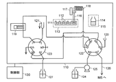
- FIG. 1 is a schematic configuration diagram of an automatic sample introduction apparatus according to an embodiment of the present invention.
- the automatic sample introduction apparatus of the present embodiment introduces a sample into a mass spectrometer (MS), and includes an operation unit 110 that performs sample introduction operation and a control unit 130 that controls the operation unit 110. Is done.
- MS mass spectrometer
- the operation unit 110 includes a plate mounting unit 113 on which the sample plate 111 is set, an internal standard solution container mounting unit 115 on which the internal standard solution container 114 is set, and a cylindrical needle having a tapered tip.
- a needle drive mechanism 117 including a motor and the like for moving the needle 116 in the horizontal and vertical directions, a sample loop 118 connected to the proximal end of the needle 116, a metering pump 119, an injection port 120, a needle 116, a cleaning port 121 for cleaning the sample loop 118, a first flow path switching valve 122, and a second flow path switching valve 123 are included.
- Each of the first flow path switching valve 122 and the second flow path switching valve 123 is a 6-port 2-position valve.
- the communication state between matching ports can be switched.
- the port a of the first flow path switching valve 122 has a liquid feeding pump 125 connected to the carrier liquid reservoir 124, the port b has a sample loop 118, the port c has a metering pump 119, and the port d has a second flow.
- a port g of the path switching valve 123 is connected to the port e, the injection port 120 is connected to the port e, and a flow path (hereinafter referred to as “analysis flow path 126”) to the mass spectrometer is connected to the port f.
- the port g of the second flow path switching valve 123 is the port d of the first flow path switching valve 122, the port h is the drain, the port i is the metering pump 119, the port j is the cleaning port 121, A cleaning liquid reservoir 127 storing a cleaning liquid is connected to the port l, and the port k is closed.
- the metering pump 119 and the liquid feed pump 125 correspond to the suction / discharge means in the present invention.
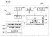
- the control unit 130 is a computer such as a personal computer, and as shown in FIG. 2, a monitor (display unit) including a CPU (Central Processing Unit) 131 that is a central processing unit, a memory 132, an LCD (Liquid Crystal Display), and the like. ) 133, an input unit 134 made up of a keyboard, a mouse, and the like, and a storage unit 135 made up of a mass storage device such as an HDD (Hard Disk Drive) or an SSD (Solid State Drive) are connected to each other.
- the storage unit 135 stores an OS (Operating System) 136 and an injection operation control program 137.
- OS Operating System
- the control unit 130 further has an interface (I / F) for direct connection with an external device (here, the operation unit 110) and connection with the external device via a network such as a LAN (Local Area Network). 138 and is connected to the operation unit 110 via the I / F 138 via a network cable or a wireless LAN.
- I / F interface for direct connection with an external device (here, the operation unit 110) and connection with the external device via a network such as a LAN (Local Area Network).
- a network such as a LAN (Local Area Network).
- FIG. 2 shows an internal standard solution suction control unit 139, a sample solution suction control unit 140, and a discharge control unit 141 as related to the injection operation control program 137.
- These are basically functional means realized by software by the CPU 131 reading the injection operation control program 137 into the memory 132 and executing it.
- the injection operation control program 137 is not necessarily a single program, and may be a function incorporated in a part of a program for controlling the mass spectrometer, for example, and its form is not particularly limited.
- sample pretreatment is performed in the following procedure. That is, the person in charge of the test cuts out a portion containing the blood of each subject from the dried filter paper blood sheet sent from a medical institution or the like, and accommodates each in a well on the sample plate. Then, a predetermined amount (for example, 100 ⁇ L) of blood component extraction liquid is added to each well in which the filter paper is accommodated.
- a liquid for example, methanol
- a liquid containing an internal standard substance is used instead of a liquid containing an internal standard substance as in the prior art.
- sample liquid the liquid stored in each well 112 (corresponding to the sample liquid container in the present invention) of the sample plate 111 is referred to as “sample liquid”.
- the person in charge of the inspection sets the internal standard solution container 114 containing the liquid containing the internal standard substance (internal standard solution) on the internal standard solution container mounting unit 115 of the automatic sample introduction device.
- the sample solution and the internal standard solution are collected in the operation unit 110 under the control of the injection operation control program 137, and the mass spectrometer. To be introduced. A procedure for introducing the sample solution and the internal standard solution at this time will be described with reference to the flowchart of FIG. 3 and FIGS. 1, 4, and 5.
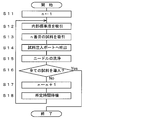
- the injection operation control program 137 sets a variable n representing the number of the well 112 on the sample plate 111 to 1 (step S11).
- the internal standard solution suction control unit 139 causes the needle 116 to suck the internal standard solution stored in the internal standard solution container 114 (step S12). Specifically, first, the first flow path switching valve 122 and the second flow path switching valve 123 are controlled to bring the ports a to f and g to l into the communication state shown in FIG. As a result, the sample loop 118 and the metering pump 119 are connected via the first flow path switching valve 122 and the second flow path switching valve 123, and further attached to the carrier liquid reservoir 124 via the first flow path switching valve 122. The liquid feed pump 125 and the analysis flow path 126 are connected.
- the needle drive mechanism 117 is controlled to insert the tip of the needle 116 into the internal standard solution container 114 (FIG. 1), and a predetermined amount (for example, 1 ⁇ L) of the internal standard solution is sucked by the metering pump 119.
- the sample liquid suction control unit 140 controls the needle driving mechanism 117 to insert the tip of the needle 116 into the nth (that is, first) well 112 on the sample plate 111 (FIG. 4), and further measures.
- the pump 119 is controlled to cause the sample liquid in the well 112 to be sucked into the needle 116 by a predetermined amount (for example, 1 ⁇ L) (step S13). As described above, a predetermined amount of the sample solution and the internal standard solution are collected in the needle 116.
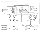
- the discharge control unit 141 controls the needle drive mechanism 117 to insert the needle 116 into the injection port 120, and puts the first flow path switching valve 122 into the state shown in FIG. Thereby, a flow path is formed from the carrier liquid reservoir 124 to the analysis flow path 126 through the liquid feed pump 125, the port a, the port b, the needle 116, the injection port 120, the port e, and the port f.
- the carrier liquid fed by the liquid feeding pump 125 passes through the sample loop 118 and the needle 116, the sample liquid and the internal standard liquid that existed in the sample loop 118 and / or the needle 116 are used. Is pushed away by the carrier liquid and introduced into the mass spectrometer through the injection port 120 and the analysis flow path 126 (step S14).
- the injection operation control program 137 executes needle cleaning using the cleaning port 121 (step S15). Specifically, the second flow path switching valve 123 is switched as shown in FIG. 6 so that the cleaning liquid reservoir 127 and the metering pump 119 communicate with each other, and the cleaning liquid in the cleaning liquid reservoir 127 is transferred to the syringe of the metering pump 119 by the suction operation of the metering pump 119. Aspirate into. Subsequently, the needle 116 and the sample loop 118 are disconnected from the flow of the carrier liquid by switching the first flow path switching valve 122 as shown in FIG.
- the needle driving mechanism 117 is controlled to insert the needle 116 into the cleaning port 121, and the cleaning liquid in the syringe is sent out by the discharge operation of the metering pump 119.
- the cleaning liquid is fed into the sample loop 118, passes through the needle 116, and is discharged to the cleaning port 121.
- the cleaning liquid is repeatedly sucked and discharged, and the cleaning operation is finished when a predetermined amount of liquid is delivered.
- the injection operation control program 137 determines whether or not all the samples on the sample plate 111 have been introduced (step S16). The variable n is incremented (step S17). Then, it waits for a predetermined time until the next analysis can be performed in the mass spectrometer (step S18), and the process returns to step S12. Thereafter, steps S12 to S18 are repeatedly executed, and a series of sample injection operations are completed when introduction of all the samples is completed (when it becomes Yes in step S16).
- the internal standard solution and the sample solution stored in separate containers are sequentially collected by the needles, and these are simultaneously introduced into the mass spectrometer. .
- the sample solution is sucked from different wells 112 (sample solution containers) each time, whereas the internal standard solution is collected from the same internal standard solution container 114 each time. That is, the internal standard solution remaining in the internal standard solution container 114 when one sample introduction is completed is used when the sample is introduced next time. For this reason, the internal standard substance is not consumed more than the amount necessary for analysis as in the prior art.
- Such a sample introduction method can be suitably used for analysis using a dry filter paper blood sample as a sample, such as the above-described neonatal mass screening, and can be similarly applied to analysis using a normal liquid as a sample.
- the internal standard solution is accommodated in a container prepared separately from the sample plate 111 and set in the internal standard solution container mounting unit 115.
- the present invention is not limited to this, and the internal standard solution is used as the sample plate.
- the sample liquid on 111 may be stored in a well 112 that does not store the sample liquid.
- the well 112 corresponds to the internal standard solution container in the present invention.
- Two or more internal standard solution containers may be set in the sample introduction device according to the present invention. In this case, for example, the internal standard solution is sucked from one internal standard solution container until a predetermined number of sample introductions are completed, and thereafter, the internal standard solution is collected from another internal standard solution container.
- the sample introduction device after inserting the front-end
- the sample solution and the internal standard solution are discharged from the tip and introduced into the analysis channel
- the sample introduction device according to the present invention is not limited to this.
- the sample solution and the internal standard solution are discharged from the tip of the needle by the discharge operation of the metering pump, and the sample solution and the internal standard solution are introduced into the analysis channel. May be.
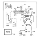
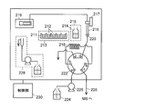
- a liquid sample introducing device having such a configuration will be described with reference to FIGS.
- subjected, and description is abbreviate
- omitted suitably.
- the flow path switching valve 222 is a 6-port 2-position valve.
- the port a has a liquid feed pump 225 connected to the carrier liquid reservoir 224, the port b has an upstream side of the sample loop 218, the port c has a drain,
- the injection port 220 is connected to the port d, the downstream side of the sample loop 218 is connected to the port e, and the analysis flow path 226 reaching the mass spectrometer is connected to the port f.
- the metering pump 219 is provided independently of the flow path switching valve 222, and a pipe having a needle 216 is connected to the metering pump 219.
- a needle cleaning flow path 228 including a cleaning liquid container, a liquid feeding pump, a needle cleaning port, and a pipe connecting them is provided. It has been.
- the configuration of the control unit 230 is the same as that in FIG. In this embodiment, the metering pump 219 corresponds to the suction / discharge means in the present invention.
- step S 12 the flow path switching valve 222 is brought into the communication state shown in FIG. 8, the needle 216 is inserted into the internal standard solution container 214, and a predetermined amount of the internal standard solution is supplied by the suction operation of the metering pump 219.
- step S13 as shown in FIG. 9, the needle 216 is inserted into a predetermined well 212 (nth well) on the sample plate 211, and a predetermined amount of sample liquid is collected in the needle 216 by the suction operation of the metering pump 219. To do.
- step S14 the needle 216 is inserted into the injection port 220 as shown in FIG. 10, and the internal standard solution and the sample solution collected in steps S12 and S13 are introduced into the sample loop 218 by the discharge operation of the metering pump 219. Thereafter, the flow path switching valve is switched to the communication state shown in FIG. As a result, the sample loop 218 is inserted in the flow of the carrier liquid, and the internal standard solution and the sample liquid held in the sample loop 218 are introduced into the mass spectrometer through the analysis flow path 226.
- the sample was introduced into the mass spectrometer using the sample introduction method according to the present invention and the conventional sample introduction method, and the results of quantitative analysis using the mass spectrometer were compared.
- the same dry filter paper blood sample as described above was accommodated in the well of the sample plate, 100 ⁇ L of methanol was added, and blood components were extracted by shaking at 45 ° C. for 45 minutes. And the obtained extract (sample liquid) was moved to the well of another sample plate, and was set to the automatic sample introduction apparatus. Further, an appropriate amount of the same internal standard solution as described above was accommodated in a vial and set in an automatic sample introduction apparatus. In the automatic sample introduction device, 1 ⁇ L each of the extract in the well and the internal standard solution in the vial was sampled and introduced into the mass spectrometer at the same time.
- the mass spectrometer performs mass spectrometry based on the conditions defined in the kit, and based on the obtained mass spectrum, 20 kinds of indicator substances (amino acids Ala, Cit, Leu, Met, Phe , Tyr, Val, acylcarnitine C0, C2, C3, C4, C5, C5DC, C6, C8, C10, C12, C14, C16, C18) and their corresponding internal standard peak areas were derived. Then, using the ratio of the peak areas of each indicator substance and internal standard substance thus obtained, and a calibration curve prepared by measuring a plurality of types of samples having different concentration ratios of the indicator substance and internal standard substance in advance. The concentration of each indicator substance in the extract was calculated.
- indicator substances amino acids Ala, Cit, Leu, Met, Phe , Tyr, Val
Landscapes
- Physics & Mathematics (AREA)
- Health & Medical Sciences (AREA)
- Life Sciences & Earth Sciences (AREA)
- Chemical & Material Sciences (AREA)
- Analytical Chemistry (AREA)
- Biochemistry (AREA)
- General Health & Medical Sciences (AREA)
- General Physics & Mathematics (AREA)
- Immunology (AREA)
- Pathology (AREA)
- Sampling And Sample Adjustment (AREA)
- Other Investigation Or Analysis Of Materials By Electrical Means (AREA)
Abstract
分析装置に試料及び内部標準物質を導入するに際し、管状のニードルの先端を内部標準液容器に挿入し、該先端から該内部標準液容器に収容された内部標準物質を含む液体である内部標準液を予め定められた量吸引する内部標準液吸引工程(S12)と、該先端を試料液容器に挿入し、該先端から該試料液容器に収容された試料液を予め定められた量吸引する試料液吸引工程(S13)とを実行した後、該先端を分析装置へ至る流路に連通する注入ポートへ挿入し、該先端から前記試料液及び前記内部標準液を吐出する吐出工程(S14)を実行する。このとき、複数回の試料導入においてそれぞれ同一の内部標準液容器から前記内部標準液を吸引することにより、1回の試料導入で消費される内部標準液を分析に供される最小限の量に抑えることが可能となる。
Description
本発明は、自動試料導入装置、試料導入方法、及びプログラムに関する。
近年、フェニルケトン尿症等の先天性代謝疾患の早期発見を目的として、新生児から採取した血液サンプルを質量分析装置で分析して疾患の指標物質を定量する新生児マススクリーニングと呼ばれる検査が広く行われている(例えば特許文献1を参照)。新生児マススクリーニングでは、まず医療機関等において、被検者である新生児の血液を濾紙に少量染み込ませて乾燥させる。そして、検査機関において検査担当者が前記濾紙の血液含浸箇所をパンチング(切り出し)してサンプルプレート(例えば96穴マイクロプレート)上の1つのウェル(サンプル収容用の凹部)に収容する。なお、新生児マススクリーニングでは、通常、多数のサンプルを連続的に質量分析するため、前記サンプルプレートの各ウェルにはそれぞれ異なる被験者から採取した血液を含む濾紙が収容される。続いて、前記濾紙が収容された各ウェルに内部標準物質を含む溶液(内部標準液)を一定量ずつ添加して、濾紙中の血液成分を該溶液中に抽出する。その後、各ウェル中の溶液(以下「試料・内部標準混合液」とよぶ)を別のサンプルプレートの各ウェルに移し、該サンプルプレートを自動試料導入装置(オートサンプラ)にセットする。これにより、該自動試料導入装置により各ウェル中の試料・内部標準混合液が順次採取されて質量分析装置に導入される。
従来の自動試料導入装置による試料導入の手順について図13及び図14を用いて説明する。まず、自動試料導入装置の内部に設けられたニードル316の先端がサンプルプレート311のウェル312に挿入される。このとき、2つの流路切替バルブ322、323に設けられたポートa~lは図13で示すように連通した状態となっている。すなわち、ニードル316及びその基端に接続されたサンプルループ318は、流路切替バルブ322を介して計量ポンプ319に接続されている。続いて、計量ポンプ319の働きによりウェル312内の試料・内部標準混合液がニードル316の先端から所定量吸引される。
次に、ニードル316の先端を注入ポート320に挿入すると共に流路切替バルブ322による流路の切り替えを行う。これにより、流路切替バルブ322に設けられたポートa~fは図14で示すように連通した状態となる。すなわち、ニードル316及びサンプルループ318が、キャリア液体リザーバ324から質量分析装置(MS)へと至るキャリア液体流路の流れに介挿される。その結果、ニードル316及び/又はサンプルループ318中に保持されていた試料・内部標準混合液がキャリア液体によって押し流され、質量分析装置に導入される。
質量分析装置では、導入された試料・内部標準混合液中の各成分がイオン化され、質量毎に分離されて検出される。これにより、横軸を質量電荷比(m/z)、縦軸を信号強度とするマススペクトルが生成され、該マススペクトル上における疾患指標物質の信号強度と内部標準物質の信号強度との比に基づいて、前記疾患指標物質が定量される。そして、この定量値が予め定められた閾値を超えた場合に陽性と判定される。
ところで、上記の内部標準物質には、定量対象の物質に類似した特性を有し、マススペクトル上で定量対象物質のピークに近く且つ該ピークと分離可能な位置にピークを持つ物質を用いる必要がある。そこで、上記の新生児マススクリーニングにおける内部標準物質としては、疾患指標物質である所定のアミノ酸又は所定のアシルカルニチンの一部を安定同位体で置換したものが使用される。しかしながら、これらは一般に製造コストが高く高価である。新生児マススクリーニングでは一度の質量分析で多くの疾患を検査できるよう、上述の内部標準液として複数の疾患指標物質に対応した複数種類(例えば20種類)の内部標準物質を混合したものが使用されており、前記内部標準液のコストが検査コストを押し上げる一因となっている。そのため、1回の検査で使用する内部標準液の量を低減することが求められている。
なお、ここでは新生児マススクリーニングを例に挙げたが、これに限らず質量分析装置やその他の分析装置を用いた種々の目的の定量分析において、分析コストの低減のために内部標準物質の使用量を抑えることが望まれている。
本発明は上記の点に鑑みてなされたものであり、その目的とするところは内部標準物質を用いた定量分析(内部標準法による定量分析)において、内部標準物質の使用量を低減することにある。
上記課題を解決するために成された本発明に係る自動試料導入装置は、
a) 管状のニードルと、
b) 分析流路に連通する注入ポートと、
c) 前記ニードルと、試料液容器、内部標準液容器、及び前記注入ポートとの相対位置を変化させる移動手段と、
d) 前記ニードルを通して液体を吸引及び吐出する吸引・吐出手段と、
e) 前記移動手段及び前記吸引・吐出手段を制御する制御手段と、
を備え、
更に、前記制御手段が、
f) 前記ニードルの先端を前記内部標準液容器に挿入させ、該先端から該内部標準液容器に収容された内部標準物質を含む液体である内部標準液を予め定められた量吸引させる内部標準液吸引制御手段と、
g) 前記ニードルの先端を前記試料液容器に挿入させ、該先端から該試料液容器に収容された試料液を予め定められた量吸引させる試料液吸引制御手段と、
h) 前記ニードルの先端を前記注入ポートへ挿入させ、前記内部標準液及び前記試料液を該先端から吐出する吐出制御手段と、
を有し、
前記内部標準液吸引制御手段と前記試料液吸引制御手段とをこの順又は逆順で動作させた後、前記吐出制御手段を動作させることにより前記分析流路への試料導入を行うものであって、複数回の試料導入においてそれぞれ同一の内部標準液容器から前記内部標準液を吸引させるものであることを特徴としている。
a) 管状のニードルと、
b) 分析流路に連通する注入ポートと、
c) 前記ニードルと、試料液容器、内部標準液容器、及び前記注入ポートとの相対位置を変化させる移動手段と、
d) 前記ニードルを通して液体を吸引及び吐出する吸引・吐出手段と、
e) 前記移動手段及び前記吸引・吐出手段を制御する制御手段と、
を備え、
更に、前記制御手段が、
f) 前記ニードルの先端を前記内部標準液容器に挿入させ、該先端から該内部標準液容器に収容された内部標準物質を含む液体である内部標準液を予め定められた量吸引させる内部標準液吸引制御手段と、
g) 前記ニードルの先端を前記試料液容器に挿入させ、該先端から該試料液容器に収容された試料液を予め定められた量吸引させる試料液吸引制御手段と、
h) 前記ニードルの先端を前記注入ポートへ挿入させ、前記内部標準液及び前記試料液を該先端から吐出する吐出制御手段と、
を有し、
前記内部標準液吸引制御手段と前記試料液吸引制御手段とをこの順又は逆順で動作させた後、前記吐出制御手段を動作させることにより前記分析流路への試料導入を行うものであって、複数回の試料導入においてそれぞれ同一の内部標準液容器から前記内部標準液を吸引させるものであることを特徴としている。
前記制御部は、前記試料液と前記内部標準液のどちらを先にニードルに吸引させるものとしてもよい。また、前記移動手段はニードルのみを移動させることで前記相対位置を変化させるものとしてもよく、ニードルに加えて又は代えて試料液容器、内部標準液容器、及び注入ポートの少なくとも1つを移動させることにより前記相対位置を変化させるものとしてもよい。
従来、自動試料導入装置を利用した定量分析では、検査担当者が試料と内部標準物質を予め混合した状態で試料液容器(ウェル)に収容しておき、該自動試料導入装置が該試料液容器内の液体を所定量吸引して注入ポートから分析流路に導入していた。例えば、上述の新生児マススクリーニングの場合、検査担当者が乾燥濾紙血液サンプルを100 μLの内部標準液で抽出した後、得られた抽出液(血液成分と内部標準物質の混合液)を前記試料液容器に収容し、自動試料導入装置が該抽出液をニードルで1 μL採取して分析流路に導入していた。従って、試料液容器に収容された内部標準液の大部分(この例では100 μL中の99 μL)は分析に供されず無駄に消費されていたことになる。
これに対し、上記本発明に係る自動試料導入装置を利用した定量分析では、それぞれ別の容器(すなわち前記試料液容器と前記内部標準液容器)に収容された試料液と内部標準液とをニードルで所定量ずつ吸引した後に該ニードルを注入ポートに挿入し、前記試料液と内部標準液を一度に分析流路に導入する。例えば、上述の新生児マススクリーニングの場合、乾燥濾紙血液サンプルは内部標準物質を含まない所定の溶媒(例えばメタノール)100 μLで抽出し、得られた抽出液(試料液)を試料液容器に収容しておく。一方で、内部標準液は前記試料液容器とは別に設けられた内部標準液容器に収容しておく。そして、自動試料導入装置が、内部標準液容器内の内部標準液と試料液容器内の試料液をそれぞれ1 μLずつ採取し、これらを一度に分析流路に注入する。このときニードルで吸引されずに内部標準液容器に残った内部標準液は次の分析、すなわち別の試料液容器に収容された試料液の導入時に使用される。そのため、従来のように内部標準液の大部分が無駄になることはない。その結果、1回の分析(すなわち1つの試料液容器に収容された試料液の分析)で消費される内部標準液を分析に供される最小限の量(この例の場合1 μL)に抑えることが可能となる。
また、上記課題を解決するために成された本発明に係る試料導入方法は、
a) 管状のニードルの先端を内部標準液容器に挿入し、該先端から該内部標準液容器に収容された内部標準物質を含む液体である内部標準液を予め定められた量吸引する内部標準液吸引工程と、
b) 該先端を試料液容器に挿入し、該先端から該試料液容器に収容された試料液を予め定められた量吸引する試料液吸引工程と、
をこの順又はこの逆順で実行した後、
c) 該先端を分析流路に連通する注入ポートへ挿入し、該先端から前記試料液及び前記内部標準液を吐出する吐出工程、
を実行することにより前記分析流路への試料導入を行うものであって、
複数回の試料導入においてそれぞれ同一の内部標準液容器から前記内部標準液を吸引することを特徴としている。
a) 管状のニードルの先端を内部標準液容器に挿入し、該先端から該内部標準液容器に収容された内部標準物質を含む液体である内部標準液を予め定められた量吸引する内部標準液吸引工程と、
b) 該先端を試料液容器に挿入し、該先端から該試料液容器に収容された試料液を予め定められた量吸引する試料液吸引工程と、
をこの順又はこの逆順で実行した後、
c) 該先端を分析流路に連通する注入ポートへ挿入し、該先端から前記試料液及び前記内部標準液を吐出する吐出工程、
を実行することにより前記分析流路への試料導入を行うものであって、
複数回の試料導入においてそれぞれ同一の内部標準液容器から前記内部標準液を吸引することを特徴としている。
上記の通り、本発明に係る自動試料導入装置及び試料導入方法によれば、内部標準法による定量分析における内部標準物質の消費量を抑えることが可能となる。
以下、本発明を実施するための最良の形態について図面を参照しつつ説明する。図1は本発明の一実施形態による自動試料導入装置の概略構成図である。なお、上述の図13と共通する構成要素については下二桁が共通する符号を付し、適宜説明を省略する。本実施形態の自動試料導入装置は質量分析装置(MS)に対して試料の導入を行うものであり、試料の導入動作を行う動作部110と、動作部110を制御する制御部130とで構成される。
動作部110は、サンプルプレート111がセットされるプレート載置部113と、内部標準液容器114がセットされる内部標準液容器載置部115と、先端がテーパー状に形成された筒状のニードル116と、モータ等を含み前記ニードル116を水平方向及び鉛直方向に移動させるニードル駆動機構117と、ニードル116の基端に接続されたサンプルループ118と、計量ポンプ119と、注入ポート120と、ニードル116やサンプルループ118を洗浄するための洗浄ポート121と、第一流路切替バルブ122と、第二流路切替バルブ123とを含んでいる。
第一流路切替バルブ122及び第二流路切替バルブ123はいずれも6ポート2ポジションバルブであり、それぞれステッピングモータ等の駆動源によってバルブ内の回動部材(ロータ)を回動させることにより、隣り合うポート間の連通状態を切り替えることができる。第一流路切替バルブ122のポートaにはキャリア液体リザーバ124に接続された送液ポンプ125が、ポートbにはサンプルループ118が、ポートcには計量ポンプ119が、ポートdには第二流路切替バルブ123のポートgが、ポートeには注入ポート120が、ポートfには質量分析装置へ至る流路(以下「分析流路126」とよぶ)がそれぞれ接続されている。また、第二流路切替バルブ123のポートgには第一流路切替バルブ122のポートdが、ポートhにはドレインが、ポートiには計量ポンプ119が、ポートjには洗浄ポート121が、ポートlには洗浄液を貯留した洗浄液リザーバ127がそれぞれ接続されており、ポートkは閉鎖されている。なお、本実施形態では計量ポンプ119及び送液ポンプ125が本発明における吸引・吐出手段に相当する。
制御部130はパーソナルコンピュータ等のコンピュータであり、図2に示すように中央演算処理装置であるCPU(Central Processing Unit)131と、メモリ132と、LCD(Liquid Crystal Display)等から成るモニタ(表示部)133と、キーボードやマウス等から成る入力部134と、HDD(Hard Disk Drive)やSSD(Solid State Drive)等の大容量記憶装置から成る記憶部135とが互いに接続されている。記憶部135には、OS(Operating System)136、及び注入動作制御プログラム137が記憶されている。制御部130は、更に、外部装置(ここでは動作部110)との直接的な接続や、外部装置とのLAN(Local Area Network)などのネットワークを介した接続を司るためのインターフェース(I/F)138を備えており、該I/F138よりネットワークケーブル又は無線LANを介して動作部110に接続されている。
図2においては、注入動作制御プログラム137に係るように、内部標準液吸引制御部139、試料液吸引制御部140、及び吐出制御部141が示されている。これはいずれも基本的にはCPU131が注入動作制御プログラム137をメモリ132に読み出して実行することによりソフトウエア的に実現される機能手段である。なお、前記注入動作制御プログラム137は必ずしも単体のプログラムである必要はなく、例えば質量分析装置を制御するためのプログラムの一部に組み込まれた機能であってもよく、その形態は特に問わない。
本実施形態に係る自動試料導入装置を上述の新生児マススクリーニングに使用する場合には、まず、次のような手順で試料の前処理を行う。すなわち、検査担当者が医療機関等から送られてきた乾燥濾紙血シートから各被検者の血液が含まれる箇所を切り出し、それぞれをサンプルプレート上の各ウェルに収容する。そして、前記濾紙が収容された各ウェルに血液成分抽出用の液体を所定量(例えば100 μL)ずつ添加する。ここで、該液体としては、従来のような内部標準物質を含む液体ではなく、内部標準物質を含まない液体(例えばメタノール)を使用する。そして、前記サンプルプレートを所定温度で所定時間(例えば、45℃で45分間)振盪することにより、濾紙中の血液成分を前記液体中に抽出する。その後、各ウェル中の液体を別のサンプルプレート111の各ウェル112に移し、該サンプルプレート111を自動試料導入装置のプレート載置部113にセットする。以下、このサンプルプレート111の各ウェル112(本発明における試料液容器に相当)に収容された液体を「試料液」とよぶ。検査担当者は、更に内部標準物質を含む液(内部標準液)を収容した内部標準液容器114を自動試料導入装置の内部標準液容器載置部115にセットする。
その後、検査担当者が上述の入力部134から試料導入の開始を指示すると、注入動作制御プログラム137による制御の下に、前記動作部110において前記試料液及び内部標準液が採取され、質量分析装置に導入される。このときの試料液及び内部標準液の導入手順について図3のフローチャート、並びに図1、図4、及び図5を参照しつつ説明する。
まず、注入動作制御プログラム137が、サンプルプレート111上のウェル112の番号を表す変数nを1にセットする(ステップS11)。
次に、内部標準液吸引制御部139が、内部標準液容器114に収容された内部標準液をニードル116に吸引させる(ステップS12)。具体的には、まず第一流路切替バルブ122及び第二流路切替バルブ123を制御してポートa~f及びg~lを図1に示す連通状態にする。これにより、第一流路切替バルブ122及び第二流路切替バルブ123を介してサンプルループ118と計量ポンプ119とが接続され、更に、第一流路切替バルブ122を介してキャリア液体リザーバ124に付設された送液ポンプ125と分析流路126とが接続された状態となる。そして、ニードル駆動機構117を制御してニードル116の先端を内部標準液容器114に挿入させ(図1)、計量ポンプ119により予め定められた量(例えば1 μL)の内部標準液を吸引させる。
続いて、試料液吸引制御部140が、ニードル駆動機構117を制御してニードル116の先端をサンプルプレート111上のn番目(すなわち1番目)のウェル112に挿入させ(図4)、更に、計量ポンプ119を制御して該ウェル112中の試料液を予め定められた量(例えば1 μL)ニードル116に吸引させる(ステップS13)。以上により、ニードル116内には所定量の試料液と内部標準液とが採取された状態となる。
次に、吐出制御部141が、ニードル駆動機構117を制御してニードル116を注入ポート120に挿入させると共に、第一流路切替バルブ122を図5に示す状態にする。これにより、キャリア液体リザーバ124から送液ポンプ125、ポートa、ポートb、ニードル116、注入ポート120、ポートe、ポートf、を経て分析流路126へと至る流路が形成される。その結果、送液ポンプ125によって送給されたキャリア液体がサンプルループ118及びニードル116内を通過するようになるため、サンプルループ118及び/又はニードル116内に存在していた試料液及び内部標準液がこのキャリア液体によって押し流され、注入ポート120及び分析流路126を介して質量分析装置に導入される(ステップS14)。
その後、注入動作制御プログラム137は、洗浄ポート121を用いてニードルの洗浄を実行する(ステップS15)。具体的には、第二流路切替バルブ123を図6のように切り替えて洗浄液リザーバ127と計量ポンプ119を連通させ、計量ポンプ119の吸引動作によって洗浄液リザーバ127内の洗浄液を計量ポンプ119のシリンジ内に吸引する。続いて第一流路切替バルブ122を図7のように切り替えることでニードル116及びサンプルループ118をキャリア液体の流れから切り離す。そして、ニードル駆動機構117を制御してニードル116を洗浄ポート121に挿入させると共に、計量ポンプ119の吐出動作によって前記シリンジ内の洗浄液を送出する。これにより、洗浄液がサンプルループ118に送り込まれ、ニードル116を通過して洗浄ポート121に排出される。このような洗浄液の吸引及び吐出を繰り返し行い、所定の液量を送出した時点で洗浄動作を終了する。
洗浄動作が完了すると、注入動作制御プログラム137は、サンプルプレート111上の全ての試料を導入したか否かを判定し(ステップS16)、全試料の導入が完了していない場合には、上記の変数nをインクリメント(ステップS17)する。そして、質量分析装置において次の分析が可能となるまで所定の時間待機し(ステップS18)、ステップS12へと戻る。その後、ステップS12~S18を繰り返し実行し、全試料の導入が完了した時点(ステップS16でYesになった時点)で一連の試料注入動作を完了する。
以上の通り、本実施形態に係る液体試料導入装置によれば、それぞれ別の容器に収容された内部標準液と試料液とがニードルによって順次採取され、これらが同時に質量分析装置へと導入される。また、複数回の試料導入において、試料液はその都度異なるウェル112(試料液容器)から吸引されるのに対し、内部標準液は毎回同じ内部標準液容器114から採取される。すなわち、1回の試料導入が完了した時点で内部標準液容器114内に残った内部標準液は、次回以降の試料の導入時に使用される。そのため、従来のように分析に必要な量以上に内部標準物質を消費することがない。従って、本実施形態の構成によれば内部標準法による定量分析における内部標準物質の消費量を抑え、分析コストを低減することが可能となる。なお、こうした試料導入方法は、上述の新生児マススクリーニングのような乾燥濾紙血液サンプルを試料とした分析に好適に使用できるほか、通常の液体を試料とした分析にも同様に適用することができる。
以上の実施形態では、サンプルプレート111とは別に用意した容器に内部標準液を収容して内部標準液容器載置部115にセットするものとしたが、これに限らず、内部標準液をサンプルプレート111上の試料液が収容されていないウェル112に収容するようにしてもよい。この場合、該ウェル112が本発明における内部標準液容器に相当する。また、本発明に係る試料導入装置には、内部標準液容器を2個以上セットしてもよい。この場合、例えば所定の回数の試料導入が完了するまでは1つの内部標準液容器から内部標準液を吸引し、それ以降は別の内部標準液容器から内部標準液を採取する。
また、上記実施形態では、ニードルの先端を注入ポートに挿入した後に流路切替バルブを切り替え、ニードルとその基端に接続された流路をキャリア液体の流路中に介挿することにより、ニードル先端から試料液及び内部標準液を吐出させて分析流路に導入する構成としたが、本発明に係る試料導入装置はこれに限定されるものではない。例えば、ニードルの先端を注入ポートに挿入した後に、計量ポンプの吐出動作により該ニードルの先端から試料液及び内部標準液を吐出させて該試料液及び内部標準液を分析流路に導入するようにしてもよい。以下、こうした構成の液体試料導入装置について図8~図11を参照しつつ説明する。なお、図1と共通する構成要素については下二桁が共通する符号を付し、適宜説明を省略する。
流路切替バルブ222は6ポート2ポジションバルブであり、ポートaにはキャリア液体リザーバ224に接続された送液ポンプ225が、ポートbにはサンプルループ218の上流側が、ポートcにはドレインが、ポートdには注入ポート220が、ポートeにはサンプルループ218の下流側が、ポートfには質量分析装置に至る分析流路226がそれぞれ接続されている。計量ポンプ219は前記流路切替バルブ222とは独立に設けられており、該計量ポンプ219にはニードル216を備えた配管が接続されている。また、前記流路切替バルブ222を含む流路や計量ポンプ219を含む流路とは別に、洗浄液容器・送液ポンプ・ニードル洗浄ポート及びこれらを接続する配管から成るニードル洗浄用流路228が設けられている。制御部230の構成は図2と同様である。なお、本実施形態では計量ポンプ219が本発明における吸引・吐出手段に相当する。
この自動試料導入装置においても、図3のフローチャートと同様の手順で試料液及び内部標準液の導入が行われる。但し、ステップS12では、流路切替バルブ222を図8に示す連通状態にすると共に、ニードル216を内部標準液容器214に挿入し、計量ポンプ219の吸引動作により所定量の内部標準液をニードル216内に採取する。ステップS13では、図9に示すようにニードル216をサンプルプレート211上の所定のウェル212(n番目のウェル)に挿入し、計量ポンプ219の吸引動作により所定量の試料液をニードル216内に採取する。続くステップS14では、図10に示すようにニードル216を注入ポート220に挿入し、計量ポンプ219の吐出動作により、ステップS12及びS13で採取した内部標準液及び試料液をサンプルループ218に導入し、その後、流路切替バルブを図11に示す連通状態に切り替える。これにより、サンプルループ218がキャリア液体の流れに介挿され、該サンプルループ218内に保持されていた内部標準液及び試料液が分析流路226を経て質量分析装置に導入される。
本発明に係る試料導入方法と従来の試料導入方法とで質量分析装置への試料導入を行い、該質量分析装置による定量分析の結果を比較した。
従来法による試料導入では、直径3 mmにパンチングした乾燥濾紙血液検体をサンプルプレートのウェルに収容し、そこに新生児マススクリーニングキット(NeoBase Non-delivatized MSMS kit、パーキンエルマー製)に付属の内部標準液100 μLを添加して45℃で45分振盪することにより血液成分を抽出した。そして、得られた抽出液(試料と内部標準の混合液)を別のサンプルプレートのウェルに移して自動試料導入装置にセットした。自動試料導入装置では、該ウェルから1 μLの前記抽出液を採取して質量分析装置に導入した。
一方、本発明の方法による試料導入では、上記と同様の乾燥濾紙血液検体をサンプルプレートのウェルに収容し、メタノール100 μLを添加して45℃で45分振盪することにより血液成分を抽出した。そして、得られた抽出液(試料液)を別のサンプルプレートのウェルに移して自動試料導入装置にセットした。また、バイアル瓶に上記と同じ内部標準液を適量収容して自動試料導入装置にセットした。自動試料導入装置では、前記ウェル中の抽出液と前記バイアル瓶中の内部標準液をそれぞれ1μL採取して同時に質量分析装置へ導入した。
上記いずれの場合においても、質量分析装置では前記キットで定められた条件に基づいて質量分析を行い、得られたマススペクトルに基づいて20種類の指標物質(アミノ酸Ala, Cit, Leu, Met, Phe, Tyr, Valと、アシルカルニチンC0, C2, C3, C4, C5, C5DC, C6, C8, C10, C12, C14, C16, C18)及びそれらに対応した内部標準物質のピーク面積を導出した。そして、これにより得られた各指標物質と内部標準物質のピーク面積の比と、予め前記指標物質と内部標準物質の濃度比が異なる複数種類のサンプルを測定して作成した検量線とを用いて、前記抽出液中における各指標物質の濃度を算出した。
上記のような定量分析を、従来法と本発明の方法とでそれぞれ6回ずつ行ったところ、各指標物質の濃度の平均とCV値(変動係数)は図12に示す通りであった。以上の結果、同図から明らかなように、本発明の方法によれば、いずれの指標物質についても従来法と同程度に検出できることが確認された。
110、210…動作部
111、211、311…サンプルプレート
112、212、312…ウェル
113、213…プレート載置部
114、214…内部標準液容器
115、215…内部標準液容器載置部
116、216、316…ニードル
117、217…ニードル駆動機構
118、218、318…サンプルループ
119、219、319…計量ポンプ
120、220、320…注入ポート
121…洗浄ポート
122…第一流路切替バルブ
123…第二流路切替バルブ
222、322、323…流路切替バルブ
124、224、324…キャリア液体リザーバ
125、225…送液ポンプ
126、226…分析流路
127…洗浄液リザーバ
130、230…制御部
135…記憶部
137…注入動作制御プログラム
138…内部標準液吸引制御部
139…試料液吸引制御部
140…吐出制御部
111、211、311…サンプルプレート
112、212、312…ウェル
113、213…プレート載置部
114、214…内部標準液容器
115、215…内部標準液容器載置部
116、216、316…ニードル
117、217…ニードル駆動機構
118、218、318…サンプルループ
119、219、319…計量ポンプ
120、220、320…注入ポート
121…洗浄ポート
122…第一流路切替バルブ
123…第二流路切替バルブ
222、322、323…流路切替バルブ
124、224、324…キャリア液体リザーバ
125、225…送液ポンプ
126、226…分析流路
127…洗浄液リザーバ
130、230…制御部
135…記憶部
137…注入動作制御プログラム
138…内部標準液吸引制御部
139…試料液吸引制御部
140…吐出制御部
Claims (3)
- a) 管状のニードルと、
b) 分析流路に連通する注入ポートと、
c) 前記ニードルと、試料液容器、内部標準液容器、及び前記注入ポートとの相対位置を変化させる移動手段と、
d) 前記ニードルを通して液体を吸引及び吐出する吸引・吐出手段と、
e) 前記移動手段及び前記吸引・吐出手段を制御する制御手段と、
を備え、
更に、前記制御手段が、
f) 前記ニードルの先端を前記内部標準液容器に挿入させ、該先端から該内部標準液容器に収容された内部標準物質を含む液体である内部標準液を予め定められた量吸引させる内部標準液吸引制御手段と、
g) 前記ニードルの先端を前記試料液容器に挿入させ、該先端から該試料液容器に収容された試料液を予め定められた量吸引させる試料液吸引制御手段と、
h) 前記ニードルの先端を前記注入ポートへ挿入させ、前記内部標準液及び前記試料液を該先端から吐出する吐出制御手段と、
を有し、
前記内部標準液吸引制御手段と前記試料液吸引制御手段とをこの順又は逆順で動作させた後、前記吐出制御手段を動作させることにより前記分析流路への試料導入を行うものであって、複数回の試料導入においてそれぞれ同一の内部標準液容器から前記内部標準液を吸引させるものであることを特徴とする自動試料導入装置。 - コンピュータを請求項1に記載の制御手段として機能させることを特徴とするプログラム。
- a) 管状のニードルの先端を内部標準液容器に挿入し、該先端から該内部標準液容器に収容された内部標準物質を含む液体である内部標準液を予め定められた量吸引する内部標準液吸引工程と、
b) 該先端を試料液容器に挿入し、該先端から該試料液容器に収容された試料液を予め定められた量吸引する試料液吸引工程と、
をこの順又はこの逆順で実行した後、
c) 該先端を分析流路に連通する注入ポートへ挿入し、該先端から前記試料液及び前記内部標準液を吐出する吐出工程、
を実行することにより前記分析流路への試料導入を行うものであって、
複数回の試料導入においてそれぞれ同一の内部標準液容器から前記内部標準液を吸引することを特徴とする試料導入方法。
Priority Applications (2)
| Application Number | Priority Date | Filing Date | Title |
|---|---|---|---|
| JP2016530704A JPWO2016001979A1 (ja) | 2014-06-30 | 2014-06-30 | 自動試料導入装置、試料導入方法、及びプログラム |
| PCT/JP2014/067409 WO2016001979A1 (ja) | 2014-06-30 | 2014-06-30 | 自動試料導入装置、試料導入方法、及びプログラム |
Applications Claiming Priority (1)
| Application Number | Priority Date | Filing Date | Title |
|---|---|---|---|
| PCT/JP2014/067409 WO2016001979A1 (ja) | 2014-06-30 | 2014-06-30 | 自動試料導入装置、試料導入方法、及びプログラム |
Publications (1)
| Publication Number | Publication Date |
|---|---|
| WO2016001979A1 true WO2016001979A1 (ja) | 2016-01-07 |
Family
ID=55018581
Family Applications (1)
| Application Number | Title | Priority Date | Filing Date |
|---|---|---|---|
| PCT/JP2014/067409 Ceased WO2016001979A1 (ja) | 2014-06-30 | 2014-06-30 | 自動試料導入装置、試料導入方法、及びプログラム |
Country Status (2)
| Country | Link |
|---|---|
| JP (1) | JPWO2016001979A1 (ja) |
| WO (1) | WO2016001979A1 (ja) |
Cited By (2)
| Publication number | Priority date | Publication date | Assignee | Title |
|---|---|---|---|---|
| CN106841427A (zh) * | 2016-12-30 | 2017-06-13 | 广州市达瑞生物技术股份有限公司 | 一种检测pku和cah的串联质谱试剂盒制备及其应用 |
| JP2019124563A (ja) * | 2018-01-16 | 2019-07-25 | 国立大学法人山梨大学 | 質量分析装置、質量分析方法、質量分析システム、及び質量分析解析プログラム |
Citations (1)
| Publication number | Priority date | Publication date | Assignee | Title |
|---|---|---|---|---|
| JP2013170925A (ja) * | 2012-02-21 | 2013-09-02 | Isuzu Motors Ltd | 注射器、マイクロシリンジ、及び分析装置への注入方法 |
Family Cites Families (4)
| Publication number | Priority date | Publication date | Assignee | Title |
|---|---|---|---|---|
| JPH087202B2 (ja) * | 1990-01-08 | 1996-01-29 | 株式会社日立製作所 | 生体試料のクロマトグラフイー分析法および液体クロマトグラフ装置 |
| JP3512811B2 (ja) * | 1994-07-11 | 2004-03-31 | テクマー カンパニー | モジュール式バイアル自動サンプル装置 |
| US6998095B2 (en) * | 2003-08-15 | 2006-02-14 | Metara, Inc. | Loop dilution system |
| JP2006242720A (ja) * | 2005-03-02 | 2006-09-14 | Shimadzu Corp | 自動試料導入装置 |
-
2014
- 2014-06-30 JP JP2016530704A patent/JPWO2016001979A1/ja active Pending
- 2014-06-30 WO PCT/JP2014/067409 patent/WO2016001979A1/ja not_active Ceased
Patent Citations (1)
| Publication number | Priority date | Publication date | Assignee | Title |
|---|---|---|---|---|
| JP2013170925A (ja) * | 2012-02-21 | 2013-09-02 | Isuzu Motors Ltd | 注射器、マイクロシリンジ、及び分析装置への注入方法 |
Cited By (4)
| Publication number | Priority date | Publication date | Assignee | Title |
|---|---|---|---|---|
| CN106841427A (zh) * | 2016-12-30 | 2017-06-13 | 广州市达瑞生物技术股份有限公司 | 一种检测pku和cah的串联质谱试剂盒制备及其应用 |
| CN106841427B (zh) * | 2016-12-30 | 2019-05-14 | 广州市达瑞生物技术股份有限公司 | 一种检测pku和cah的串联质谱试剂盒 |
| JP2019124563A (ja) * | 2018-01-16 | 2019-07-25 | 国立大学法人山梨大学 | 質量分析装置、質量分析方法、質量分析システム、及び質量分析解析プログラム |
| JP7158642B2 (ja) | 2018-01-16 | 2022-10-24 | 国立大学法人山梨大学 | 質量分析装置及び質量分析システム |
Also Published As
| Publication number | Publication date |
|---|---|
| JPWO2016001979A1 (ja) | 2017-04-27 |
Similar Documents
| Publication | Publication Date | Title |
|---|---|---|
| Maciel et al. | New materials in sample preparation: Recent advances and future trends | |
| US11585792B2 (en) | Open port sampling interface | |
| KR102543773B1 (ko) | 수집 프로브 및 이들의 사용 방법 | |
| JP6971025B2 (ja) | インライン希釈及び自動校正icp−ms化学種分析 | |
| CN103370616B (zh) | 用于样品制备和分析的自动化系统及方法 | |
| US10668464B2 (en) | Liquid sample introduction device | |
| US20240162026A1 (en) | Systems and methods for quantifying an analyte extracted from a sample | |
| CN111356925B (zh) | 自动分析系统 | |
| JP6843932B2 (ja) | サンプルインジェクタ | |
| CN106662556A (zh) | 制备型液相色谱装置及制备条件探索方法 | |
| US11802853B2 (en) | Sample injection device and sample injection system | |
| CN108195984A (zh) | 一种干血斑中多种维生素的检测方法和检测系统 | |
| CN108414608B (zh) | 一种对复杂反应体系中化学成分实时在线监测分析的方法及其专用装置 | |
| US6802228B2 (en) | Microsample analysis system using syringe pump and injection port | |
| CN107643393B (zh) | 样本分析仪及其清洗方法、含有溶血剂成分的液体的用途 | |
| WO2016001979A1 (ja) | 自動試料導入装置、試料導入方法、及びプログラム | |
| CN103575586B (zh) | 样品分离器 | |
| CN111699393A (zh) | 生物体试样分析系统 | |
| WO2019111311A1 (ja) | 生体試料自動分析システム | |
| CH700283A1 (de) | Probenhandling- und Injektions-System für die HPLC mit verschliessbaren Pipettenspitzen. | |
| CN114689831A (zh) | 一种血液分析仪和血液分析方法 | |
| JP2016165665A (ja) | 液体混合方法及び液体混合装置 | |
| Forss | On-line HPLC | |
| CA2968394A1 (en) | Automated nano-flow electrospray of microliters of sample |
Legal Events
| Date | Code | Title | Description |
|---|---|---|---|
| 121 | Ep: the epo has been informed by wipo that ep was designated in this application |
Ref document number: 14896714 Country of ref document: EP Kind code of ref document: A1 |
|
| ENP | Entry into the national phase |
Ref document number: 2016530704 Country of ref document: JP Kind code of ref document: A |
|
| NENP | Non-entry into the national phase |
Ref country code: DE |
|
| 122 | Ep: pct application non-entry in european phase |
Ref document number: 14896714 Country of ref document: EP Kind code of ref document: A1 |