WO2015194323A1 - ネットワークシステム、通信制御方法および記憶媒体 - Google Patents
ネットワークシステム、通信制御方法および記憶媒体 Download PDFInfo
- Publication number
- WO2015194323A1 WO2015194323A1 PCT/JP2015/064955 JP2015064955W WO2015194323A1 WO 2015194323 A1 WO2015194323 A1 WO 2015194323A1 JP 2015064955 W JP2015064955 W JP 2015064955W WO 2015194323 A1 WO2015194323 A1 WO 2015194323A1
- Authority
- WO
- WIPO (PCT)
- Prior art keywords
- communication
- ecu
- unit
- reliability
- network
- Prior art date
Links
- 238000004891 communication Methods 0.000 title claims abstract description 376
- 238000000034 method Methods 0.000 title claims description 7
- 238000012544 monitoring process Methods 0.000 claims abstract description 29
- 238000012545 processing Methods 0.000 claims description 80
- 230000008569 process Effects 0.000 claims description 4
- 230000005540 biological transmission Effects 0.000 description 73
- 230000006870 function Effects 0.000 description 65
- 238000012986 modification Methods 0.000 description 16
- 230000004048 modification Effects 0.000 description 16
- 238000004364 calculation method Methods 0.000 description 10
- 230000004044 response Effects 0.000 description 10
- 230000009471 action Effects 0.000 description 8
- 238000010586 diagram Methods 0.000 description 8
- 238000003745 diagnosis Methods 0.000 description 4
- 239000000470 constituent Substances 0.000 description 3
- 238000005259 measurement Methods 0.000 description 3
- 238000012546 transfer Methods 0.000 description 3
- 238000005516 engineering process Methods 0.000 description 2
- 239000000446 fuel Substances 0.000 description 2
- 238000010295 mobile communication Methods 0.000 description 2
- 238000006467 substitution reaction Methods 0.000 description 2
- 230000002411 adverse Effects 0.000 description 1
- 230000004397 blinking Effects 0.000 description 1
- 230000008859 change Effects 0.000 description 1
- 238000011161 development Methods 0.000 description 1
- 230000000694 effects Effects 0.000 description 1
- 238000004519 manufacturing process Methods 0.000 description 1
- 230000002093 peripheral effect Effects 0.000 description 1
- 230000008439 repair process Effects 0.000 description 1
- 238000012795 verification Methods 0.000 description 1
- XLYOFNOQVPJJNP-UHFFFAOYSA-N water Substances O XLYOFNOQVPJJNP-UHFFFAOYSA-N 0.000 description 1
Images


Classifications
-
- H—ELECTRICITY
- H04—ELECTRIC COMMUNICATION TECHNIQUE
- H04L—TRANSMISSION OF DIGITAL INFORMATION, e.g. TELEGRAPHIC COMMUNICATION
- H04L43/00—Arrangements for monitoring or testing data switching networks
- H04L43/08—Monitoring or testing based on specific metrics, e.g. QoS, energy consumption or environmental parameters
- H04L43/0876—Network utilisation, e.g. volume of load or congestion level
- H04L43/0894—Packet rate
-
- H—ELECTRICITY
- H04—ELECTRIC COMMUNICATION TECHNIQUE
- H04L—TRANSMISSION OF DIGITAL INFORMATION, e.g. TELEGRAPHIC COMMUNICATION
- H04L43/00—Arrangements for monitoring or testing data switching networks
- H04L43/08—Monitoring or testing based on specific metrics, e.g. QoS, energy consumption or environmental parameters
-
- H—ELECTRICITY
- H04—ELECTRIC COMMUNICATION TECHNIQUE
- H04L—TRANSMISSION OF DIGITAL INFORMATION, e.g. TELEGRAPHIC COMMUNICATION
- H04L12/00—Data switching networks
- H04L12/28—Data switching networks characterised by path configuration, e.g. LAN [Local Area Networks] or WAN [Wide Area Networks]
-
- H—ELECTRICITY
- H04—ELECTRIC COMMUNICATION TECHNIQUE
- H04L—TRANSMISSION OF DIGITAL INFORMATION, e.g. TELEGRAPHIC COMMUNICATION
- H04L12/00—Data switching networks
- H04L12/28—Data switching networks characterised by path configuration, e.g. LAN [Local Area Networks] or WAN [Wide Area Networks]
- H04L12/46—Interconnection of networks
-
- H—ELECTRICITY
- H04—ELECTRIC COMMUNICATION TECHNIQUE
- H04L—TRANSMISSION OF DIGITAL INFORMATION, e.g. TELEGRAPHIC COMMUNICATION
- H04L12/00—Data switching networks
- H04L12/66—Arrangements for connecting between networks having differing types of switching systems, e.g. gateways
-
- H—ELECTRICITY
- H04—ELECTRIC COMMUNICATION TECHNIQUE
- H04L—TRANSMISSION OF DIGITAL INFORMATION, e.g. TELEGRAPHIC COMMUNICATION
- H04L43/00—Arrangements for monitoring or testing data switching networks
- H04L43/16—Threshold monitoring
-
- H—ELECTRICITY
- H04—ELECTRIC COMMUNICATION TECHNIQUE
- H04L—TRANSMISSION OF DIGITAL INFORMATION, e.g. TELEGRAPHIC COMMUNICATION
- H04L67/00—Network arrangements or protocols for supporting network services or applications
- H04L67/01—Protocols
- H04L67/12—Protocols specially adapted for proprietary or special-purpose networking environments, e.g. medical networks, sensor networks, networks in vehicles or remote metering networks
Definitions
- One aspect of the present disclosure relates to a network system.
- a technology for permitting communication of a reliable communication node by controlling access to the in-vehicle communication network based on authentication is known (see, for example, Patent Document 1).
- this technology by identifying whether or not the tool connected to the connector for connecting an external device is a genuine product, an illegal act is performed on the in-vehicle device connected to the in-vehicle communication network via the connector. Stop that.
- one aspect of the present disclosure is intended to make a communication node function according to the reliability of the communication node connected to the in-vehicle communication network.
- a network system including one or more communication nodes and a gateway.
- the gateway is configured to monitor a communication parameter in communication with a communication node newly connected to the network system, and based on whether the communication parameter monitored by the monitoring unit satisfies a predetermined communication condition.
- a communication control unit that determines the reliability of the newly connected communication node and changes the predetermined communication condition according to the reliability.
- the communication node can function according to the reliability of the communication node connected to the in-vehicle communication network.
- movement of a vehicle-mounted communication network It is a figure which shows the example of application of a vehicle-mounted communication network. It is a figure which shows the modification of the hardware constitutions of a network controller. It is a functional block diagram which shows the modification of a network controller. It is a figure which shows the modification of an in-vehicle communication network. It is a figure which shows the modification of an in-vehicle communication network.
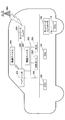
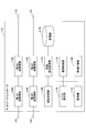
- FIG. 1 shows an embodiment of an in-vehicle communication network.
- the in-vehicle communication network is composed of a single network or an aggregate of multiple networks, and each network is connected to communication nodes such as one or more parts, devices, and electronic control units (ECU). Is done.
- An external connection port to which a tool such as a vehicle diagnostic device is connected may be connected to the in-vehicle communication network.
- Each communication node may be replaced at the time of repair, or non-genuine products such as non-genuine products and custom products may be connected to the network. Furthermore, an unspecified tool or measurement device may be connected to the external connection port.
- an ECU is applied as an example of the communication node.
- the in-vehicle communication network includes a head unit 100, an ECU 102, an ECU 104, a network controller 106, an ECU 110, an on-board diagnostic (OBD) port 202, an ECU 204, an information device 302, a network unit 304, and a wireless device 400.
- OBD on-board diagnostic
- the head unit 100, the ECU 102, the ECU 104, and the network controller 106 are connected by a first communication bus 108, so that CAN (Controller Area Network), Ethernet (registered trademark), a local area network (LAN: Local Area). Configure a first network such as Network).
- the head unit 100, the OBD port 202, and the ECU 204 constitute a second network such as CAN, Ethernet (registered trademark), or a local area network by being connected by a second communication bus 206.
- the head unit 100, the information device 302, and the network unit 304 constitute a third network such as CAN, Ethernet (registered trademark), and local area network by being connected by a third communication bus 306.
- the network controller 106 and the ECU 110 constitute a fourth network such as CAN, Ethernet (registered trademark), or local area network by being connected by the fourth communication bus 112.
- the head unit 100 has multimedia functions such as navigation, audio, and video, performs wireless communication with the wireless device 400, and reproduces music and moving image data transmitted from the wireless device 400. Further, as described later, the head unit 100 operates based on information input from the network unit 304.
- the ECUs 102, 104, 110, and 204 mainly perform engine control such as ignition timing, fuel adjustment, throttle opening, valve timing, and idling adjustment.
- the ECUs 102, 104, 110, and 204 include brake control such as an anti-lock brake system (ABS), traction control, airbags, air conditioners, meters, immobilizers, room lamps, etc. It is also possible to control the electrical components.
- ABS anti-lock brake system
- traction control airbags, air conditioners, meters, immobilizers, room lamps, etc. It is also possible to control the electrical components.
- the network controller 106 determines whether or not to connect the ECU 110 to the first network according to the reliability of the ECU 110, and sets the band to be allocated to the ECU 110 according to the reliability. Then, transmission control such as setting a packet transmitted by the ECU 110 that outputs to the first network is performed. For example, the network controller 106 restricts the bandwidth to be assigned or restricts packets to be transferred to the first network by adjusting communication parameters for the ECU 110.
- the OBD port 202 is a port for connecting a dedicated terminal or the like when acquiring the content of the fault diagnosis recorded by the OBD.
- a vehicle mechanic or the like can acquire the fault diagnosis content acquired from the OBD port 202 and analyze the content. For example, when a failure diagnosis is made, the OBD notifies the location and content of the failure by turning on or blinking a lamp or ringing a buzzer sound and records a code corresponding to the content.
- a radar detector, an external meter, and the like can be connected to the OBD port 202, and water temperature, boost pressure, fuel consumption, and the like during traveling can be measured.
- the information device 302 stores information acquired by the network unit 304 and outputs it to the head unit 100.
- the network unit 304 obtains map data from a server (not shown) connected to a network (not shown) connected to the access point 500 by performing wireless communication with the access point 500, Music data can be downloaded. For example, when the head unit 100 functions as navigation, the network unit 304 downloads updated map data, and when the head unit 100 functions as audio, the network unit 304 downloads music and video data. . Further, as will be described later, the network unit 304 performs service communication from a server (not shown) connected to a network (not shown) connected to the access point 500 by performing wireless communication with the access point 500. You can receive the offer.
- the wireless device 400 includes a wireless device such as a wireless LAN module, and performs wireless communication with the head unit 100.
- the network controller 106 and the ECU 110 are newly added after the in-vehicle communication network is once configured. That is, when a communication node such as the ECU 110 is newly added to the first network, the network controller 106 is connected to the first communication bus 108, and the ECU 110 to be newly added is connected to the network controller 106.
- a case where a communication node such as the ECU 110 is newly added to the first network will be described.
- the present invention can also be applied to a case where a communication node such as an ECU is newly added to the second network and the third network.
- FIG. 2 shows a first network of the in-vehicle communication network of FIG.
- the first network is a bus-type network
- the head unit 100, the plurality of ECUs 102 and 104, and the network controller 106 are connected to the first communication bus 108, and the network controller 106 is connected.
- ECU 110 is connected.
- FIG. 3 is a hardware configuration diagram of the ECU 102 according to the present embodiment.
- the ECU 102 includes a CPU (Central Processing Unit) 1024 that controls the operation of the entire ECU 102 and a ROM (Read Only Memory) that stores a program used to drive the CPU 1024. 1026.
- the ECU 102 includes a RAM (Random Access Memory) 1028 used as a work area of the CPU 1024, and an address bus and a data bus for electrically connecting the above components as shown in FIG. A bus line 1023 is provided.
- a bus line 1023 is provided.
- the ECU 102 includes a communication unit 1030 that transmits transmission data input from the CPU 1024 to the transceiver 1032 to transmit the transmission data to the first communication bus 108 and inputs reception data input from the transceiver 1032 to the CPU 1024.
- the CPU 1024, ROM 1026, RAM 1028, communication unit 1030, and bus line 1023 can also be configured as the microcontroller 1022.
- the ECU 102 also includes a transceiver 1032 that transmits transmission data input from the communication unit 1030 to the first communication bus 108 and inputs reception data received from the first communication bus 108 to the communication unit 1030.
- the hardware configuration of the ECU 102 shown in FIG. 3 can also be applied to the ECU 104, the ECU 110, and the ECU 204.
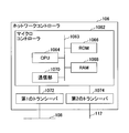
- FIG. 4 is a hardware configuration diagram of the network controller 106 according to the present embodiment.
- the network controller 106 of this embodiment includes a CPU 1064 that controls the operation of the entire network controller 106 and a ROM 1066 that stores a program used to drive the CPU 1064.
- the network controller 106 includes a RAM 1068 used as a work area of the CPU 1064 and a bus line 1063 such as an address bus and a data bus for electrically connecting the above-described components as shown in FIG. Prepare.
- the network controller 106 outputs transmission data input from the CPU 1064 to the first transceiver 1072 and the second transceiver 1074, thereby transmitting them to the first communication bus 108 and the fourth communication bus 112, respectively.
- the CPU 1064, the ROM 1066, the RAM 1068, and the communication unit 1063 may be configured as the microcontroller 1062.
- the network controller 106 transmits the transmission data input from the communication unit 1070 to the first communication bus 108, and inputs the reception data received from the first communication bus 108 to the communication unit 1070.
- the transceiver 1072 includes a second transceiver 1074 that transmits transmission data input from the communication unit 1070 to the fourth communication bus 112 and inputs reception data received from the fourth communication bus 112 to the communication unit 1070. .
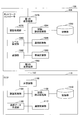
- FIG. 5 is a functional block diagram of the network controller 106 and the ECU 110 of the present embodiment. As shown in FIG. 5, the network controller 106 and the ECU 110 are wired to be communicable.
- the ECU 110 includes a transmission / reception unit 1102, an authentication processing unit 1104, a transmission data creation unit 1106, a storage / reading processing unit 1108, a storage unit 1110, and a communication control unit 1112.
- Each of these units is a function realized by one of the constituent elements shown in FIG. 3 being operated by a command from the CPU 1024 in accordance with an ECU program developed from the ROM 1026 on the RAM 1028, or is functioned. Means.
- each functional configuration of the ECU 110 will be described in detail with reference to FIGS. 3 and 5.
- FIGS. 3 and 5 In the following, in describing each functional component of the ECU 110, a relationship with main components for realizing each functional component of the ECU 110 among the components illustrated in FIG. 3 will also be described. .
- the transmission / reception unit 1102 of the ECU 110 shown in FIG. 5 is realized by a command from the CPU 1024 shown in FIG. 3 and the communication unit 1030 shown in FIG. 3, and is connected to the network controller via the fourth network.
- Various data (or information) is transmitted / received to / from 106.
- the storage / reading processing unit 1108 of the ECU 110 shown in FIG. 5 is realized by an instruction from the CPU 1024 shown in FIG. 3, and stores various data in the storage unit 1110 or stored in the storage unit 1110. Processing to read out various data.
- the storage unit 1110 stores an authentication key such as a node ID for identifying the ECU 110, a reliability level of the ECU 110, and a password shared with the network controller 106. Note that the node ID may be stored in the storage unit 1110 in advance, or may be input to the storage unit 1110 when the user of the ECU 110 uses the node ID.
- the node ID of the present embodiment indicates identification information such as language, characters, symbols, or various signs used to uniquely identify the ECU. Further, the node ID may be identification information in which at least two of the language, characters, symbols, and various indicia are combined.
- the storage unit 1110 of the ECU 110 illustrated in FIG. 5 is realized by the ROM 1026 illustrated in FIG. 3, and stores an authentication key such as a node ID of the ECU 110, a reliability level of the ECU 110, and a password shared with the network controller 106.
- an authentication key such as a node ID of the ECU 110, a reliability level of the ECU 110, and a password shared with the network controller 106.
- the authentication processing unit 1104 of the ECU 110 shown in FIG. 5 is realized by a command from the CPU 1024 shown in FIG. 3, and requests the network controller 106 for authentication.
- the authentication processing unit 1104 causes the storage / reading processing unit 1108 to read the node ID and the reliability level stored in the storage unit 1110, create an authentication request attached with the node ID and the reliability level, and transmit / receive From the unit 1102. Further, when a challenge transmitted from the network controller 106 is received by the transmission / reception unit 1102, the authentication processing unit 1104 acquires a nonce (random number) attached to the challenge, and stores the storage unit in the storage / reading processing unit 1108. The authentication key stored in 1110 is read.
- the authentication processing unit 1104 performs a predetermined calculation by combining the acquired nonce and the authentication key, and transmits the calculation result from the transmission / reception unit 1102 as a response. Further, when an authentication response transmitted from the network controller 106 is received by the transmission / reception unit 1102, the authentication processing unit 1104 is authenticated by the communication control unit 1112 if the authentication response indicates that communication is permitted. Notify that. Further, for example, the authentication processing unit 1104 can perform authentication with the network controller 106 with each other by EAP-TLS, and can perform authentication with PEAP. The network controller 106 can also function as a RADIUS server.
- the transmission data creation unit 1106 of the ECU 110 shown in FIG. 5 is realized by a command from the CPU 1024 shown in FIG. 3, creates various data (or information) to be transmitted to other communication nodes, and transmits and receives 1102 to transmit.
- the communication control unit 1112 of the ECU 110 shown in FIG. 5 is realized by a command from the CPU 1024 shown in FIG. 3 and the communication unit 1030 shown in FIG.
- the communication control unit 1112 controls transmission of the transmission data created by the transmission data creation unit 1106.
- the network controller 106 includes a first transmission / reception unit 1076, an authentication processing unit 1078, a level setting unit 1080, a monitoring unit 1082, a storage / reading processing unit 1084, a storage unit 1086, a communication control unit 1088, a bandwidth measuring unit 1090, and a second Transmission / reception unit 1092.
- Each of these units is a function realized by any one of the constituent elements shown in FIG. 4 being operated by a command from the CPU 1062 according to the network controller program developed from the ROM 1066 on the RAM 1068, or a function Means.
- each functional configuration of the network controller 106 will be described in detail with reference to FIGS. 4 and 5.
- the main components for realizing each functional component of the network controller 106 among the components illustrated in FIG. explain the relationship.
- the first transmission / reception unit 1076 of the network controller 106 shown in FIG. 5 is realized by a command from the CPU 1064 shown in FIG. 4 and the communication unit 1070 shown in FIG. Through this, various data (or information) is transmitted / received to / from other ECUs (ECUs 102 and 104) or the head unit 100.
- the second transmission / reception unit 1092 of the network controller 106 shown in FIG. 5 is realized by a command from the CPU 1064 shown in FIG. 4 and the communication unit 1070 shown in FIG. Via the ECU 110, various data (or information) is transmitted and received.
- the level setting unit 1080 of the network controller 106 shown in FIG. 5 is realized by a command from the CPU 1064 shown in FIG. 4, and sets the level of reliability of the ECU 110.
- the level of reliability is classified into a genuine product level, a quasi-genuine product level, a market product level, a quasi-market product level, and an uncertified level.
- the genuine level ECU is a genuine product sold by a manufacturer that manufactures and sells a product such as a vehicle, and is certified by the manufacturer that manufactures and sells the product, and has the highest reliability.
- the quasi-regular product level ECU has a special standard and performance that a manufacturer that manufactures and sells products such as vehicles instructs a component manufacturer such as a component manufacturer to manufacture, and is equivalent to a regular product level ECU. Having the above performance, it is the second most reliable next to the regular level ECU.
- the market-level ECU is a non-genuine product that is a general-purpose part made according to a general standard, has the same performance as the regular-level ECU, and is compatible with the regular-level ECU. Reliable next to regular-level ECUs.
- the semi-market level ECU is a general-purpose part made according to a general standard, and has the same performance as the regular level ECU, but is not guaranteed to be compatible with the regular level ECU. .
- the semi-market level ECU is the second most reliable after the market level ECU.
- the non-certified level ECU is a general-purpose part manufactured according to a general standard, and is not guaranteed to be compatible with a regular level ECU.
- An unauthenticated ECU is the least reliable.
- the level of reliability is an example, and it can be classified into 2-4 types, or 6 or more types. The contents of each classification can also be set as appropriate.
- the storage / reading processing unit 1084 of the network controller 106 shown in FIG. 5 is realized by an instruction from the CPU 1064 shown in FIG. 4, stores various data in the storage unit 1086, and is stored in the storage unit 1086. To read various data.
- the storage unit 1086 of the network controller 106 shown in FIG. 5 is realized by the ROM 1066 shown in FIG. 4, and is a node that describes a node ID for identifying an ECU that can communicate when authenticating the ECU. An ID table and an authentication key such as a password shared with ECU 110 are stored. Further, the storage unit 1086 stores a reliability level communication control content correspondence table. The reliability level communication control content correspondence table will be described later.
- FIG. 6 shows a reliability level communication control correspondence table in which reliability levels are associated with communication control contents.
- a communication band that can be set as a band to be used (usage band) is controlled by the transmission side, and the function can be fully utilized.
- the use band is controlled by the transmission side, but the function is limited.
- the network bandwidth is controlled by the network controller 106, and the function is limited.
- ECUs with a reliability level of near-market level are limited to the band that can be used and the functions that can guarantee the safety, and the surrounding nodes are informed of the dangerous state, and the dangerous nodes are made safe. Move to a state where it can be disconnected.
- the use band and the function are strongly limited to a level at which safety can be guaranteed.
- FIG. 6 shows an example, and the content of communication control may be set differently from FIG.
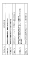
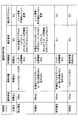
- FIG. 7 shows an example of the reliability level communication control content correspondence table.
- the reliability level communication control content correspondence table associates each reliability level by associating the specific content of communication control.
- the reliability level, the communication band, the communication target, the use function, the violation standard, and the action at the time of the violation are associated with each other.
- the communication band is a band used for communication between the network controller 106 and the ECU 110
- the communication target is a partner with which the ECU 100 can communicate.
- the use function is a function that can be used by the ECU 110, and is information that can be referred to or acquired by the ECU 110.
- the violation criterion is a criterion for determining the behavior of the ECU, and the action at the time of violation is a process performed on the ECU determined to correspond to the violation criterion.
- the ECU whose reliability level is a genuine product level is not limited in terms of communication band, communication target, and usage function, and is not set for violation standards and actions for violations.
- An ECU whose reliability level is a semi-regular product level can be controlled in a narrower range than an ECU whose reliability level is a normal product level, such as 1 Mbps, and the communication target can communicate with other than sensitive communication nodes.
- Functions are limited to functions published by the vendor supplying the ECU.
- the violation standard is when trying to access in a band exceeding 1 Mbps or when trying to access a function other than the function disclosed by the vendor.
- the level of reliability is, for example, the reliability of the market level. The level is changed to a lower level.
- An ECU whose reliability level is a marketed product level can be controlled in a narrower range than an ECU whose reliability level is a semi-regular product level such as 100 kbps, and the communication target is a communication node that can be accessed by an ECU at the marketed product level And the use function is limited to the function disclosed by the vendor supplying the ECU.
- the violation criteria are when trying to access a communication node other than the communication node designated as an accessible node, or when trying to access a function other than the function disclosed by the vendor. For example, the level is changed to a low reliability level such as a quasi-market product level.
- An ECU whose reliability level is a semi-market product level can be controlled in a narrower range than an ECU whose reliability level is a market level such as 10 kbps, and the communication target is a node that can be accessed by an ECU at the market level. It is limited to the designated node, and the function to be used is limited to the function disclosed by the vendor supplying the ECU. No violation criteria and no action for violations are set. This is because an ECU whose reliability level is a quasi-market level is strongly limited in communication band and function to a level at which safety can be guaranteed.
- the ECU whose reliability level is the non-certified product level can be controlled in a narrower range than the ECU whose reliability level is 10 kbps, such as 10 kbps, the communication target is limited to the head unit 100, and the usage function is Limited to obtaining speed information. No violation criteria and no action for violations are set. This is because an ECU whose reliability level is a non-certified product level is strongly limited in communication band and function to a level at which safety can be guaranteed.
- FIG. 7 shows an example, and the content of communication control may be set differently from FIG.
- the authentication processing unit 1078 of the network controller 106 shown in FIG. 5 is realized by an instruction from the CPU 1064 shown in FIG.
- the authentication processing unit 1078 acquires the node ID and the reliability level attached to the authentication request.
- the authentication processing unit 1078 causes the storage / reading processing unit 1084 to read the node ID table stored in the storage unit 1086, and determines whether the node ID attached to the authentication request is described. When the node ID attached to the authentication request is described in the node ID table, the authentication processing unit 1078 generates a Nonce (random number) and transmits it from the second transmission / reception unit 1092.
- the authentication processing unit 1078 performs a predetermined calculation in the same manner as the ECU 110 by combining the generated nonce and the authentication key, and a result calculated by the ECU 110 is received from the ECU 110 by the second transmitting / receiving unit 1092
- the authentication processing is performed by collating the calculation result received by the second transmission / reception unit 1092 with the calculation result by the authentication processing unit 1078.
- the authentication processing unit 1078 creates an authentication response accompanied by information indicating that the authentication was successful if the result of matching is the same, and authentication accompanied by information indicating that the authentication could not be performed if the result of the matching was not found
- a response is created and transmitted from the second transmission / reception unit 1092.
- the authentication processing unit 1078 notifies the communication control unit 1088 that the authentication has been successful when they match as a result of the collation.
- the authentication processing unit 1078 may perform authentication with the ECU 110 by using EAP-TLS (Extensible Authentication Authentication Protocol Transport Layer Security) or authentication by PEAP (protected EAP). it can.
- EAP-TLS Extensible Authentication Authentication Protocol Transport Layer Security
- PEAP protected EAP
- the network controller 106 can also function as a RADIUS server.
- the monitoring unit 1082 of the network controller 106 shown in FIG. 5 is realized by the command from the CPU 1064 shown in FIG. 4 and the communication unit 1070 shown in FIG. 4, and the newly connected ECU 110 transmits the packet.
- the behavior of the ECU 110 such as the bandwidth to be used and the access destination of the ECU 110 is monitored.
- the communication control unit 1088 of the network controller 106 shown in FIG. 5 is realized by the command from the CPU 1064 shown in FIG. 4 and the communication unit 1070 shown in FIG.
- the communication control unit 1088 causes the storage / reading processing unit 1084 to read the reliability level communication control content correspondence table stored in the storage unit 1086 and set the level.
- ECU 110 is controlled based on a communication band, a communication target, and a use function associated with the reliability level determined by unit 1080.
- the communication control unit 1088 determines whether or not the violation criterion is met according to the behavior of the ECU 110 monitored by the monitoring unit 1082 during communication with the ECU 110, and in the case of the violation action Accordingly, the reliability level is determined to be changed, and the reliability level set in the level setting unit 1080 is updated.
- a bandwidth measuring unit 1090 of the network controller 106 shown in FIG. 5 is realized by a command from the CPU 1064 shown in FIG. 4 and a communication unit 1070 shown in FIG. 4, and between the network controller 106 and the ECU 110. Measure the bandwidth used for communication.
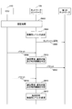
- FIG. 8 shows an embodiment of the operation of the in-vehicle communication network.
- an authentication key such as a password is preset in the ECU 110 and the network controller 106, and the ECU 110 and the network controller 106 have an authentication key according to a predetermined algorithm, and Calculate by combining Nonce.
- step S802 the authentication processing unit 1104 of the ECU 110 creates an authentication request accompanied by the node ID and the reliability level.
- step S804 the transmission / reception unit 1102 of the ECU 110 transmits the authentication request created by the authentication processing unit 1104 to the network controller 106.
- step S806 when the authentication request is received by the second transmission / reception unit 1092 of the network controller 106, the authentication processing unit 1078 acquires the authentication request.
- the authentication processing unit 1078 checks the node ID attached to the authentication request and the reliability level.
- step S808 the authentication processing unit 1078 of the network controller 106 generates a nonce after confirming that communication is possible between the own network controller 106 and the ECU 110 based on the node ID.
- the authentication processing unit 1075 can also inquire the ECU 110 for the node ID again. If it is not possible to confirm that communication is possible even after inquiring a predetermined number of times, the node ID as the account can be account-locked.
- step S810 the second transmission / reception unit 1092 of the network controller 106 transmits a nonce (challenge) generated by the authentication processing unit 1078 to the ECU 110.
- step S812 when the nonce is received by the transmission / reception unit 1102 of the ECU 110, the authentication processing unit 1104 calculates by combining the authentication key and the nonce received by the transmission / reception unit 1102.
- step S814 the authentication processing unit 1078 of the network controller 106 calculates by combining the authentication key and the generated nonce.
- step S816 the transmission / reception unit 1102 of the ECU 110 transmits the result calculated by the authentication processing unit 1104 to the network controller 106 as a response.
- step S818 when the response is received by the second transmission / reception unit 1092 of the network controller 106, the authentication processing unit 1078 collates the calculation result in step S814 with the calculation result transmitted from the ECU 110 in step S816.
- the ECU 110 is authenticated.
- step S820 the authentication processing unit 1078 of the network controller 106 transmits the authentication result in step S818 from the second transmission / reception unit 1092 to the ECU 110.
- the authentication processing unit 1078 sets the reliability level of the ECU 110 in the level setting unit 1080 and notifies the communication control unit 1088 that the authentication is successful.
- the network controller 106 can determine whether or not communication with the newly connected ECU 110 is possible, and can set the reliability level of the ECU 110 when communication is possible.
- the sequence chart shown in FIG. 8 is an example, and processing can be performed in an order different from the order of the sequence chart. For example, steps S814 and S816 may be reversed.
- FIG. 9 shows an embodiment of the operation of the in-vehicle communication network.
- FIG. 9 shows operations after the ECU 110 is authenticated by the network controller 106.
- step S902 the authentication processing unit 1078 of the network controller 106 authenticates the ECU 110.
- the authentication processing unit 1078 succeeds in the authentication of the ECU 110.
- step S904 when the authentication of the ECU 110 is successful, the authentication processing unit 1078 of the network controller 106 sets the reliability level of the ECU 110 in the level setting unit 1080 and notifies the communication control unit 1088 that the authentication of the ECU 110 is successful. To do.
- step S906 the communication control unit 1088 of the network controller 106 notifies the second transmission / reception unit 1076 that the entity has been added to the head unit 100, the ECU 102, and the ECU 104 that constitute the first network.
- step S908 the transmission data creation unit 1106 of the ECU 110 creates a packet accompanied by the transmission data, and the communication control unit 1112 transmits the packet created by the transmission data creation unit 1106 from the transmission / reception unit 1102.
- step S910 the packet transmitted from the ECU 110 is received by the second transmission / reception unit 1092 of the network controller 106 and input to the communication control unit 1088.
- the communication control unit 1088 causes the storage / read processing unit 1084 to acquire the reliability level communication control content correspondence table stored in the storage unit 1086 and transmit the packet.
- the communication control unit 1088 refers to the communication band associated with the reliability level of the ECU 110 in the reliability level communication control content correspondence table, the communication target, and the function to be used, and whether or not the packet transmitted from the ECU 110 is satisfied. Determine.
- step S912 when it is determined in the reliability level communication control content correspondence table that the packet transmitted from the ECU 110 satisfies the communication band, the communication target, and the function to be used associated with the reliability level of the ECU 110, The communication control unit 1088 transmits the packet from the first transmission / reception unit 1076 to the first network.
- step S914 the transmission data creation unit 1106 of the ECU 110 creates a packet accompanied by the transmission data, and the communication control unit 1112 transmits the packet created by the transmission data creation unit 1106 from the transmission / reception unit 1102.
- step S916 the packet transmitted from the ECU 110 is received by the second transmission / reception unit 1092 of the network controller 106 and input to the communication control unit 1088.
- the communication control unit 1088 causes the storage / read processing unit 1084 to acquire the reliability level communication control content correspondence table stored in the storage unit 1086 and transmit the packet.
- the communication control unit 1088 refers to the communication band associated with the reliability level of the ECU 110 in the reliability level communication control content correspondence table, the communication target, and the function to be used, and whether or not the packet transmitted from the ECU 110 is satisfied. Determine.
- step S918 when it is determined in the reliability level communication control content correspondence table that the packet transmitted from the ECU 110 does not satisfy the communication band associated with the reliability level of the ECU 110, the communication target, and the function to be used.
- the communication control unit 1088 rejects the packet transfer. Further, the communication control unit 1088 determines whether or not a violation criterion associated with the reliability level of the ECU 110 in the reliability level communication control content correspondence table is satisfied, and changes the reliability level of the ECU 110 if applicable. .
- the communication The control unit 1088 can also limit the function to be used by a packet transmitted from the ECU 110 after the determination. Moreover, the communication control part 1088 can also restrict
- the communication control unit 1088 can also transmit the packet with a delay. Further, the communication control unit 1088 can reduce the frequency of transferring a packet from the ECU 110. Further, the communication control unit 1088 can invalidate the packet by transferring a part of the packet from the ECU 110 and destroying the remaining packet.
- the network controller 106 can determine whether or not to transfer the packet transmitted from the ECU 110 to the first network according to the reliability level of the newly connected ECU 110. Therefore, even after the network controller 106 authenticates the ECU 110, even if the packet transmitted from the ECU 110 is transferred to the first network, a security-safe packet can be transferred.
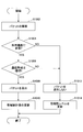
- FIG. 10 shows an embodiment of the operation of the in-vehicle communication network.
- FIG. 10 shows a process in which the network controller 106 determines a packet transmitted from the ECU 110. That is, the processing of steps S910, S916, and S918 in FIG. 9 is shown.
- step S1002 the monitoring unit 1082 of the network controller 106 analyzes the packet transmitted from the ECU 110. Specifically, the monitoring unit 1082 analyzes a band in which the ECU 110 transmits a packet, a function used by the packet, and the like.
- step S1004 the communication control unit 1088 of the network controller 106 causes the storage / read processing unit 1084 to read the reliability level communication control content correspondence table stored in the storage unit 1086. Further, the communication control unit 1088 determines whether or not the use function of the packet analyzed by the monitoring unit 1082 matches the use function of the reliability level communication control content correspondence table.
- step S1006 when the packet usage function analyzed by the monitoring unit 1082 matches the usage function of the reliability level communication control content correspondence table, the communication control unit 1088 determines that the communication bandwidth of the packet analyzed by the monitoring unit 1082 is It is determined whether or not the communication band of the reliability level communication control content correspondence table is satisfied.
- step S1008 when it is determined that the communication band of the packet analyzed by the monitoring unit 1082 satisfies the communication band of the reliability level communication control content correspondence table, the communication control unit 1088 transmits the packet from the first transmission / reception unit 1076. Send.
- step S1010 the bandwidth measuring unit 1090 of the network controller 106 measures and updates the bandwidth used for communication between the network controller 106 and the ECU 110.
- the updated bandwidth is used when determining the communication bandwidth in step S1006 for a packet transmitted thereafter.
- step S1012 if the packet usage function analyzed by the monitoring unit 1082 in step S1004 does not match the usage function of the reliability level communication control content correspondence table, or the packet communication bandwidth analyzed by the monitoring unit 1082 in step S1006 Does not satisfy the communication band of the reliability level communication control content correspondence table, the communication control unit 1088 does not transmit the packet.
- step S1014 the communication control unit 1088 of the network controller 106 determines whether or not the violation criterion is met according to the behavior of the ECU 110 monitored by the monitoring unit 1082, and if so, the action at the time of violation is taken. Therefore, it is determined that the reliability level is changed, and the reliability level set in the level setting unit 1080 is updated.
- the network controller 106 can determine whether or not the packet transmitted from the newly connected ECU 110 is safe, and can transfer the packet determined to be safe to the first network.
- bus network in which the head unit 100, the plurality of ECUs 102 and 104, and the network controller 106 are connected to the first bus 108 and the ECU 110 is connected to the network controller 106 has been described. Not limited to bus-type networks.
- FIG. 11 shows an example in which the first network is applied to a star network.
- the head unit 100, the ECU 102, the ECU 104, and the ECU 110 are radially connected to the network controller 114 with the network controller 114 serving as a hub.
- ECU 110 is a newly connected communication node.
- the newly connected ECU 110 is connected to the network controller 114 that already configures the first network.
- the present invention can also be applied to a network other than the first network, for example, the second to fourth networks.
- the network controller 114 and the head unit 100 are connected by a fifth communication bus 116, the network controller 114 and the ECU 102 are connected by a sixth communication bus 118, the network controller 114 and the ECU 104 are connected by a seventh communication bus 120, Network controller 114 and ECU 110 are connected by an eighth communication bus 122.
- the configuration described above can be applied to ECU 102, ECU 104, and ECU 110, but network controller 114 is different from the configuration of network controller 106 because four nodes are connected.
- FIG. 12 is a hardware configuration diagram of the network controller 114.
- the network controller 114 includes a CPU 1144 that controls the operation of the entire network controller 114 and a ROM 1146 that stores a program used to drive the CPU 1144.
- the network controller 114 includes a RAM 1148 used as a work area for the CPU 1144 and a bus line 1143 such as an address bus and a data bus for electrically connecting the above components as shown in FIG. Prepare.
- the network controller 114 outputs transmission data input from the CPU 1144 to the first transceiver 1152, the second transceiver 1154, the third transceiver 1156, and the fourth transceiver 1158, respectively, so that the fifth communication is performed. Transmit to bus 116, sixth communication bus 118, seventh communication bus 120, and eighth communication bus 122, first transceiver 1152, second transceiver 1154, third transceiver 1156, and fourth A communication unit 1150 is provided for inputting received data input from the transceiver 1158 to the CPU 1144.
- the CPU 1144, the ROM 1146, the RAM 1148, and the communication unit 1150 can be configured as the microcontroller 1142.
- the network controller 114 transmits the transmission data input from the communication unit 1150 to the fifth communication bus 116, and inputs the reception data received from the fifth communication bus 116 to the communication unit 1150.
- a transceiver 1152 is provided.
- the network controller 114 transmits the transmission data input from the communication unit 1150 to the sixth communication bus 118 and the second transceiver 1154 that inputs the reception data received from the sixth communication bus 118 to the communication unit 1150. Is provided.
- the network controller 114 transmits the transmission data input from the communication unit 1150 to the seventh communication bus 120 and inputs the reception data received from the seventh communication bus 120 to the communication unit 1150.
- a transceiver 1156 is provided.
- the network controller 114 transmits the transmission data input from the communication unit 1150 to the eighth communication bus 122 and the fourth transceiver 1158 that inputs the reception data received from the eighth communication bus 122 to the communication unit 1150. Is provided.
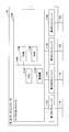
- FIG. 13 is a functional block diagram of the network controller 114.
- the network controller 114 includes a first transmission / reception unit 1160, a second transmission / reception unit 1162, a third transmission / reception unit 1164, a fourth transmission / reception unit 1166, an authentication processing unit 1168, a level setting unit 1170, a monitoring unit 1172, storage / reading A processing unit 1174, a storage unit 1176, a communication control unit 1178, and a band measurement unit 1180 are included.
- Each of these units is a function realized by any one of the constituent elements shown in FIG. 12 being operated by an instruction from the CPU 1144 according to the network controller program expanded from the ROM 1146 to the RAM 1148, or a function Means.
- each functional configuration of the network controller 114 will be described in detail with reference to FIGS. 12 and 13.
- the main components for realizing the functional components of the network controller 114 are described. Explain the relationship.
- the first transmission / reception unit 1160 of the network controller 114 shown in FIG. 13 is realized by a command from the CPU 1144 shown in FIG. 12 and the communication unit 1150 shown in FIG.
- Various data (or information) is exchanged with the head unit 100 via 116.
- the second transmission / reception unit 1162 of the network controller 114 shown in FIG. 13 is realized by a command from the CPU 1144 shown in FIG. 12 and the communication unit 1150 shown in FIG.
- Various data (or information) is transmitted to and received from the ECU 102 via 118.
- the third transmission / reception unit 1164 of the network controller 114 shown in FIG. 13 is realized by a command from the CPU 1144 shown in FIG. 12 and the communication unit 1150 shown in FIG.
- Various data (or information) is transmitted to and received from the ECU 104 via 120.
- the fourth transmission / reception unit 1166 of the network controller 114 shown in FIG. 13 is realized by an instruction from the CPU 1144 shown in FIG. 12 and the communication unit 1150 shown in FIG. Various data (or information) is transmitted / received to / from ECU 110 via 122.
- the level setting unit 1170 of the network controller 114 shown in FIG. 13 is realized by a command from the CPU 1144 shown in FIG. 12, and sets the level of reliability of the ECU 110.
- the level of reliability is classified into a genuine product level, a quasi-genuine product level, a market product level, a quasi-market product level, and an uncertified level. As the reliability level, those described above can be applied.
- the storage / reading processing unit 1174 of the network controller 114 shown in FIG. 13 is realized by an instruction from the CPU 1144 shown in FIG. 12, stores various data in the storage unit 1176, and is stored in the storage unit 1176. To read various data.
- the storage unit 1176 stores a node ID table in which node IDs for identifying ECUs that can communicate when authenticating the ECU are described. Further, the storage unit 1176 stores a reliability level communication control content correspondence table. The above-described reliability level communication control content correspondence table can be applied.
- the storage unit 1176 of the network controller 114 shown in FIG. 13 is realized by the ROM 1146 shown in FIG. 12, and is a node that describes a node ID for identifying an ECU that can communicate when authenticating the ECU. An ID table and an authentication key such as a password shared with ECU 110 are stored. Further, the storage unit 1076 stores a reliability level communication control content correspondence table. The above-described reliability level communication control content correspondence table can be applied.
- the authentication processing unit 1168 of the network controller 114 shown in FIG. 13 is realized by an instruction from the CPU 1144 shown in FIG.
- the authentication processing unit 1168 acquires a node ID and a reliability level attached to the authentication request.
- the authentication processing unit 1168 causes the storage / reading processing unit 1174 to read the node ID table stored in the storage unit 1176, and determines whether or not the node ID attached to the authentication request is described.
- the authentication processing unit 1168 generates a Nonce (random number) and transmits it from the fourth transmission / reception unit 1166.
- the authentication processing unit 1168 performs a predetermined calculation in the same manner as the ECU 110 by combining the generated nonce and the authentication key, and a result calculated by the ECU 110 is received from the ECU 110 by the fourth transmission / reception unit 1166
- the authentication processing is performed by collating the calculation result received by the fourth transmission / reception unit 1166 with the calculation result by the authentication processing unit 1168.
- the authentication processing unit 1168 creates an authentication response accompanied by information indicating that the authentication is successful if they match, and if the result of the matching does not match, the authentication processing unit 1168 adds information indicating that the authentication cannot be performed.
- a response is created and transmitted from the fourth transmission / reception unit 1166.
- the authentication processing unit 1168 notifies the communication control unit 1178 that the authentication has been successful. Further, for example, the authentication processing unit 1168 can authenticate with the ECU 110 by using EAP-TLS and can authenticate by using PEAP.
- the network controller 106 can also function as a RADIUS server.
- the monitoring unit 1172 of the network controller 114 shown in FIG. 13 is realized by the command from the CPU 1144 shown in FIG. 12, the communication unit 1150 shown in FIG. 12, and the newly connected ECU 110 transmits the packet.
- the behavior of the ECU 110 such as the bandwidth to be used and the access destination of the ECU 110 is monitored.
- the communication control unit 1178 of the network controller 114 shown in FIG. 13 is realized by a command from the CPU 1144 shown in FIG. 12 and the communication unit 1150 shown in FIG.
- the communication control unit 1178 causes the storage / reading processing unit 1174 to read the reliability level communication control content correspondence table stored in the storage unit 1176 and set the level.
- ECU 110 is controlled based on a communication band, a communication target, and a use function associated with the reliability level determined by unit 1170.
- the communication control unit 1178 determines whether or not the violation criterion is met according to the behavior of the ECU 110 monitored by the monitoring unit 1172 during communication with the ECU 110, and in the case of the violation action Accordingly, the reliability level is determined to be changed, and the reliability level set in the level setting unit 1170 is updated.
- a bandwidth measuring unit 1180 of the network controller 114 shown in FIG. 13 is realized by a command from the CPU 1144 shown in FIG. 12 and a communication unit 1150 shown in FIG. 12, and between the network controller 114 and the ECU 110. Measure the bandwidth used for communication.
- the in-vehicle communication network can be applied not only to a bus type network but also to a star type network.
- the head unit 100 and the ECU 102 may constitute a first subnetwork
- the ECU 104 and the ECU 110 may constitute a second subnetwork.
- the network controller 114 performs the processing described above for communication such as communication between the communication nodes belonging to different sub-networks, for example, communication between the head unit 100 and the ECU 104 or ECU 110, or communication between the ECU 102 and the ECU 104 or ECU 110. It can also be done.
- the functions of ECUs and tools participating in the in-vehicle communication network can be limited according to their reliability levels.
- FIG. 14 shows a modification of the in-vehicle communication network.
- One variation of the in-vehicle communication network connects the tool to the in-vehicle communication network.
- the in-vehicle communication network includes an ECU 502, an ECU 504, an ECU 506, an ECU 508, and a network controller 510.
- ECU 502, ECU 504, ECU 506, ECU 508, and network controller 510 constitute a fifth network such as CAN, Ethernet (registered trademark), or local area network by being connected by a ninth communication bus 550.
- ECU502, ECU504, ECU506, and ECU508 can apply ECU shown in FIG.3, FIG.5,
- the transceiver 1032 is connected to the 9th communication bus
- FIG. 4 and 5 can be applied to the network controller 510.
- the first transceiver 1072 is connected to the ninth communication bus 550
- the second transceiver 1074 is connected to the tenth communication bus 560.
- the network controller 510 can also function as a gateway, a data link connector (DLC: “Data Link Connector”), and a connection port for diagnosis.
- DLC Data Link Connector
- a network communication node 600 is newly connected to the network controller 510 that also functions as a data link connector.
- ECU 110 shown in FIGS. 3 and 5 can be applied to the configuration of network communication node 600.
- a diagnostic tool such as an engine adjustment debugging tool or a development debugging tool can be connected to the network controller 510 that also functions as a diagnostic connection port.
- the network controller 510 can be adjusted by setting the access target, the use function, etc. according to the reliability level of the diagnostic tool.
- a battery as a supply part can be connected to the network controller 510.
- the network controller 510 can provide a finer management service for the genuine battery.
- the function of the network controller 106 can be mounted on the network unit 304 of FIG.
- the network unit 304 can communicate with a server (not shown) via an access point by wireless communication such as WiFi (Wi-Fi: Wireless Fidelity), Bluetooth (registered trademark), and mobile communication.
- the function of the controller 106 can change a service based on information obtained by wireless communication depending on whether the driver is a vehicle owner or a non-owner. Further, the function of the network controller 106 can adjust the communication band with the access point 500 and the priority of information input to the information device 302 based on information obtained by wireless communication.
- the access level to ECU etc. can also be changed based on the information obtained by radio
- OEM original equipment manufacturer
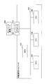
- FIG. 15 shows a third modification of the in-vehicle communication network.
- the in-vehicle communication network includes a head unit 100, a network controller 106, an ECU 110, and a network unit 304.
- the head unit 100, the network controller 106, the ECU 110, and the network unit 304 are those described above (FIGS. 3 to 5).
- the network controller 106 causes the network unit 304 to access the cloud server 700 that provides the authentication service via the head unit 100, and the authentication result from the cloud server 700 is obtained.
- the network controller 106 causes the network unit 304 to access the cloud server 700 that provides the authentication service via the head unit 100, and the authentication result from the cloud server 700 is obtained.
- the network controller 106 transmits an authentication request transmitted from the ECU 110 to the network unit 304 via the head unit 100.
- the network unit 304 redirects the authentication request transmitted from the network controller 106 by wireless transmission to the cloud server 700 that provides the authentication service via the access point 500.
- the network unit 304 accesses the cloud server 700 that provides an authentication service via the access point 500 by wireless communication such as WiFi, Bluetooth (registered trademark), and mobile communication.
- the network unit 304 authenticates the ECU 110 based on a response from the cloud server 700 that provides the authentication service.
- the network unit 304 can also cache information processed by the cloud server 700 that provides the authentication service. As a result, the performance of the network unit 304 can be improved.
- security since it is assumed that the latest information is stored in the cloud server 700, and authentication processing is performed based on the latest information, security can be further improved.
- the in-vehicle network is an example of a network system
- the ECU is an example of a communication node
- the network controller is an example of a gateway.
- the communication band, the communication target, and the use function are examples of communication parameters
- the violation standard is an example of communication conditions.
Landscapes
- Engineering & Computer Science (AREA)
- Computer Networks & Wireless Communication (AREA)
- Signal Processing (AREA)
- Environmental & Geological Engineering (AREA)
- Health & Medical Sciences (AREA)
- Computing Systems (AREA)
- General Health & Medical Sciences (AREA)
- Medical Informatics (AREA)
- Small-Scale Networks (AREA)
Abstract
Description
<車載通信ネットワーク>
図1は、車載通信ネットワークの一実施例を示す。
図3は、本実施形態に係るECU102のハードウェア構成図である。図3に示されているように、本実施形態に係るECU102は、ECU102全体の動作を制御するCPU(Central Processing Unit)1024、およびCPU1024の駆動に用いられるプログラムを記憶したROM(Read Only Memory)1026を備える。さらに、ECU102は、CPU1024のワークエリアとして使用されるRAM(Random Access Memory)1028、および上記各構成要素を図3に示されているように電気的に接続するためのアドレスバスやデータバスなどのバスライン1023を備える。
図4は、本実施形態に係るネットワークコントローラ106のハードウェア構成図である。図4に示されているように、本実施形態のネットワークコントローラ106は、ネットワークコントローラ106全体の動作を制御するCPU1064、およびCPU1064の駆動に用いられるプログラムを記憶したROM1066を備える。さらに、ネットワークコントローラ106は、CPU1064のワークエリアとして使用されるRAM1068、および上記各構成要素を図4に示されているように電気的に接続するためのアドレスバスやデータバスなどのバスライン1063を備える。
次に、本実施形態の機能構成について説明する。図5は、本実施形態のネットワークコントローラ106、およびECU110の機能ブロック図である。図5に示されるように、ネットワークコントローラ106とECU110とは、通信可能なように有線接続されている。
ECU110は、送受信部1102、認証処理部1104、送信データ作成部1106、記憶・読出処理部1108、記憶部1110、および通信制御部1112を有している。これら各部は、図3に示されている各構成要素のいずれかが、ROM1026からRAM1028上に展開されたECU用プログラムに従ったCPU1024からの命令によって動作することで実現される機能、または機能される手段である。
次に、図3および図5を用いて、ECU110の各機能構成について詳細に説明する。なお、以下では、ECU110の各機能構成部を説明するにあたって、図3に示されている各構成要素のうち、ECU110の各機能構成部を実現させるための主な構成要素との関係も説明する。
ネットワークコントローラ106は、第1の送受信部1076、認証処理部1078、レベル設定部1080、監視部1082、記憶・読出処理部1084、記憶部1086、通信制御部1088、帯域計測部1090、および第2の送受信部1092を有している。これら各部は、図4に示されている各構成要素のいずれかが、ROM1066からRAM1068上に展開されたネットワークコントローラ用プログラムに従ったCPU1062からの命令によって動作することで実現される機能、または機能される手段である。
次に、図4および図5を用いて、ネットワークコントローラ106の各機能構成について詳細に説明する。なお、以下では、ネットワークコントローラ106の各機能構成部を説明するにあたって、図4に示されている各構成要素のうち、ネットワークコントローラ106の各機能構成部を実現させるための主な構成要素との関係も説明する。
正規品レベルのECUは、車両などの製品を製造販売するメーカーによって販売されている純正品であり、製品を製造販売するメーカーによって認定されたものであり、最も信頼性が高い。
図7は、信頼性レベル通信制御内容対応テーブルの一例を示す。信頼性レベル通信制御内容対応テーブルは、信頼性レベルの各々について、通信制御の具体的内容を紐付けることによって対応付ける。
図8は、車載通信ネットワークの動作の一実施例を示す。
図13は、ネットワークコントローラ114の機能ブロック図である。
次に、図12および図13を用いて、ネットワークコントローラ114の各機能構成について詳細に説明する。なお、以下では、ネットワークコントローラ114の各機能構成部を説明するにあたって、図12に示されている各構成要素のうち、ネットワークコントローラ114の各機能構成部を実現させるための主な構成要素との関係も説明する。
図14は、車載通信ネットワークの一変形例を示す。車載通信ネットワークの一変形例は、車載通信ネットワークにツールを接続する。
図1のネットワークユニット304にネットワークコントローラ106の機能を搭載することもできる。ネットワークユニット304は、WiFi(Wi-Fi: Wireless Fidelity)、Bluetooth(登録商標)、移動体通信などの無線通信によってアクセスポイントを経由して、サーバ(図示無し)と通信を行うことができ、ネットワークコントローラ106の機能によって、運転手が車両の所有者か非所有者かによって、無線通信によって得られる情報に基づくサービスを変えることができる。また、ネットワークコントローラ106の機能によって、無線通信によって得られる情報に基づいて、アクセスポイント500との間の通信帯域や、情報デバイス302へ入力する情報の優先度を調整することもできる。また、無線通信によって得られる情報に基づいて、ECUなどへのアクセスレベルを変更することもできる。例えば、無線通信によって得られる情報がOEM(original equipment manufacturer)によって提供されるサービスであるか、サプライヤ、販売店によって提供されるサービスであるかによって、車両へのアクセスレベルを変更することができる。
図15は、車載通信ネットワークの一変形例3を示す。図15に示すように、車載通信ネットワークは、ヘッドユニット100、ネットワークコントローラ106、ECU110、およびネットワークユニット304によって構成される。ここで、ヘッドユニット100、ネットワークコントローラ106、ECU110、およびネットワークユニット304は、上述したもの(図3-図5)である。
102 ECU
104 ECU
106 ネットワークコントローラ
108 第1の通信バス
110 ECU
112 第4の通信バス
202 OBDポート
204 ECU
206 第2の通信バス
302 情報デバイス
304 ネットワークユニット
306 第3の通信バス
400 無線デバイス
500 アクセスポイント
1022 マイクロコントローラ
1024 CPU
1026 ROM
1028 RAM
1030 通信部
1032 トランシーバ
1062 マイクロコントローラ
1064 CPU
1066 ROM
1068 RAM
1070 通信部
1072 第1のトランシーバ
1074 第2のトランシーバ
1076 第1の送受信部
1078 認証処理部
1080 レベル設定部
1082 監視部
1084 記憶・読出処理部
1086 記憶部
1088 通信制御部
1090 帯域計測部
1092 第2の送受信部
1102 送受信部
1104 認証処理部
1106 送信データ作成部
1108 記憶・読出処理部
1110 記憶部
1112 通信制御部
Claims (7)
- 1以上の通信ノード、およびゲートウェイを含むネットワークシステムであって、
前記ゲートウェイは、
前記ネットワークシステムに新たに接続される通信ノードとの通信における通信パラメータを監視する監視部と、
前記監視部によって監視される通信パラメータが所定の通信条件を満たすか否かに基づいて前記新たに接続される通信ノードの信頼性を判断し、該信頼性に応じて前記所定の通信条件を変更する通信制御部と
を有する、ネットワークシステム。 - 前記ゲートウェイは、
前記新たに接続される通信ノードを認証する第1の認証処理部をさらに有し、
前記監視部は、前記第1の認証処理部によって認証された前記新たに接続される通信ノードとの通信における通信パラメータを監視し、
前記通信制御部は、前記新たに接続される通信ノードから送信される信頼性を表す情報に基づいて前記所定の通信条件を決定し、該所定の通信条件に基づいて、前記新たに接続される通信ノードの信頼性を判断し、
前記新たに接続される通信ノードは、
前記ゲートウェイへ認証を要求する際に、該新たに接続される通信ノードの信頼性を表す情報を送信する第2の認証処理部
を有する、請求項1に記載のネットワークシステム。 - 前記ゲートウェイは、
前記新たに接続される通信ノードの認証を、認証サービスを提供するクラウドサーバに要求するとともに、該クラウドサーバから認証結果を取得する第1の認証処理部をさらに有し、
前記監視部は、前記第1の認証処理部からの認証結果が成功したことを示す場合に、前記新たに接続される通信ノードとの通信における通信パラメータを監視し、
前記通信制御部は、前記新たに接続される通信ノードから送信される信頼性を表す情報に基づいて前記所定の通信条件を決定し、該所定の通信条件に基づいて、前記新たに接続される通信ノードの信頼性を判断し、
前記新たに接続される通信ノードは、
前記ゲートウェイへ認証を要求する際に、該新たに接続される通信ノードの信頼性を表す情報を送信する第2の認証処理部
を有する、請求項1に記載のネットワークシステム。 - 前記ネットワークシステムは、複数の前記通信ノードを含み、
前記複数の通信ノードによって複数のサブネットワークが構成され、
前記通信制御部は、各通信ノードが異なるサブネットワークに属する通信ノードと通信を行う際に、前記監視部によって監視される通信パラメータが所定の通信条件を満たすか否かに基づいて、前記新たに接続される通信ノードの信頼性を判断し、該信頼性に応じて、前記所定の通信条件を変更する、請求項1に記載のネットワークシステム。 - 前記監視部は、前記新たに接続される通信ノードとの通信に使用される帯域、該通信ノードの通信相手、該通信ノードが利用できる機能のいずれかを監視する、請求項1に記載のネットワークシステム。
- 1以上の通信ノード、およびゲートウェイを含むネットワークシステムにおいて、ゲートウェイが実行する通信制御方法であって、
前記ネットワークシステムに新たに接続される通信ノードとの通信における通信パラメータを監視し、
前記監視される通信パラメータが所定の通信条件を満たすか否かに基づいて、前記新たに接続される通信ノードの信頼性を判断し、
該信頼性に応じて、前記所定の通信条件を変更する、通信制御方法。 - 1以上の通信ノード、およびゲートウェイを含むネットワークシステムにおけるゲートウェイに、
前記ネットワークシステムに新たに接続される通信ノードとの通信における通信パラメータを監視させ、
前記監視される通信パラメータが所定の通信条件を満たすか否かに基づいて、前記新たに接続される通信ノードの信頼性を判断させ、
該信頼性に応じて、前記所定の通信条件を変更させる処理を実行させるプログラムを格納した、コンピュータ読み取り可能な記憶媒体。
Priority Applications (5)
| Application Number | Priority Date | Filing Date | Title |
|---|---|---|---|
| RU2016148638A RU2659489C1 (ru) | 2014-06-16 | 2015-05-25 | Сетевая система, способ управления связью и носитель данных |
| JP2016529196A JP6327344B2 (ja) | 2014-06-16 | 2015-05-25 | ネットワークシステム、通信制御方法および記憶媒体 |
| CN201580031389.9A CN106464566B (zh) | 2014-06-16 | 2015-05-25 | 网络系统、通信控制方法以及存储介质 |
| EP15809972.1A EP3157203B1 (en) | 2014-06-16 | 2015-05-25 | Network system, communication control method, and storage medium |
| US15/380,020 US20170099201A1 (en) | 2014-06-16 | 2016-12-15 | Network system, communication control method, and storage medium |
Applications Claiming Priority (2)
| Application Number | Priority Date | Filing Date | Title |
|---|---|---|---|
| JP2014123046 | 2014-06-16 | ||
| JP2014-123046 | 2014-06-16 |
Related Child Applications (1)
| Application Number | Title | Priority Date | Filing Date |
|---|---|---|---|
| US15/380,020 Continuation US20170099201A1 (en) | 2014-06-16 | 2016-12-15 | Network system, communication control method, and storage medium |
Publications (1)
| Publication Number | Publication Date |
|---|---|
| WO2015194323A1 true WO2015194323A1 (ja) | 2015-12-23 |
Family
ID=54935317
Family Applications (1)
| Application Number | Title | Priority Date | Filing Date |
|---|---|---|---|
| PCT/JP2015/064955 WO2015194323A1 (ja) | 2014-06-16 | 2015-05-25 | ネットワークシステム、通信制御方法および記憶媒体 |
Country Status (6)
| Country | Link |
|---|---|
| US (1) | US20170099201A1 (ja) |
| EP (1) | EP3157203B1 (ja) |
| JP (1) | JP6327344B2 (ja) |
| CN (1) | CN106464566B (ja) |
| RU (1) | RU2659489C1 (ja) |
| WO (1) | WO2015194323A1 (ja) |
Cited By (5)
| Publication number | Priority date | Publication date | Assignee | Title |
|---|---|---|---|---|
| CN108023872A (zh) * | 2016-11-04 | 2018-05-11 | 丰田自动车株式会社 | 车载网络系统 |
| JP2020047992A (ja) * | 2018-09-14 | 2020-03-26 | 株式会社デンソー | 車両用中継装置 |
| WO2022255005A1 (ja) * | 2021-05-31 | 2022-12-08 | パナソニック インテレクチュアル プロパティ コーポレーション オブ アメリカ | 監視システム、監視方法、監視装置および機能制限装置 |
| US12024184B2 (en) | 2018-12-25 | 2024-07-02 | Mitsubishi Electric Corporation | ECU, monitoring ECU, and CAN system |
| US12113782B2 (en) | 2018-12-12 | 2024-10-08 | Mitsubishi Electric Corporation | Information processing apparatus, information processing method and computer readable medium |
Families Citing this family (8)
| Publication number | Priority date | Publication date | Assignee | Title |
|---|---|---|---|---|
| DE102016206630A1 (de) * | 2016-04-20 | 2017-11-09 | Robert Bosch Gmbh | Verfahren und Vorrichtung zur Vermeidung von Manipulation einer Datenübertragung |
| CN108694849B (zh) * | 2018-06-05 | 2021-02-19 | 宁波市鄞州智伴信息科技有限公司 | 汽车辅助驾驶导航系统 |
| CN109257374B (zh) * | 2018-10-31 | 2021-09-03 | 百度在线网络技术(北京)有限公司 | 安全控制方法、装置和计算机设备 |
| CN112148325B (zh) * | 2019-06-28 | 2024-07-23 | 长城汽车股份有限公司 | 一种车载信息通信终端升级系统、方法及车辆 |
| CN112448816B (zh) * | 2019-08-31 | 2021-10-19 | 华为技术有限公司 | 一种身份验证方法及装置 |
| CN112689982B (zh) * | 2020-04-15 | 2022-04-29 | 华为技术有限公司 | 数据验证方法、装置及存储介质 |
| JP7355073B2 (ja) * | 2021-05-19 | 2023-10-03 | トヨタ自動車株式会社 | 車両制御装置、車両、車両制御方法及びプログラム |
| WO2023137728A1 (zh) * | 2022-01-21 | 2023-07-27 | Oppo广东移动通信有限公司 | 通信方法及通信装置 |
Citations (5)
| Publication number | Priority date | Publication date | Assignee | Title |
|---|---|---|---|---|
| JP2008092465A (ja) * | 2006-10-04 | 2008-04-17 | Internatl Business Mach Corp <Ibm> | コンピュータ端末がネットワークに接続して通信することを管理・制御するための装置および方法。 |
| JP2010087800A (ja) * | 2008-09-30 | 2010-04-15 | Fujitsu Ltd | 機器使用管理システム、情報機器、その方法及びプログラム |
| JP2012168755A (ja) * | 2011-02-15 | 2012-09-06 | Internatl Business Mach Corp <Ibm> | 異常検知システム、異常検知装置、異常検知方法、プログラムおよび記録媒体 |
| JP2013110458A (ja) * | 2011-11-17 | 2013-06-06 | Denso Corp | ゲートウェイ装置 |
| WO2014045354A1 (ja) * | 2012-09-19 | 2014-03-27 | トヨタ自動車 株式会社 | 通信装置及び通信方法 |
Family Cites Families (13)
| Publication number | Priority date | Publication date | Assignee | Title |
|---|---|---|---|---|
| ATE176744T1 (de) * | 1992-11-27 | 1999-02-15 | Ibm | Mehrfachsende-leitweglenkung zwischen bereichen |
| US7797367B1 (en) * | 1999-10-06 | 2010-09-14 | Gelvin David C | Apparatus for compact internetworked wireless integrated network sensors (WINS) |
| US7065454B2 (en) * | 2003-08-21 | 2006-06-20 | Csi Technology, Inc. | Analysis of particles in fluid |
| US8041942B2 (en) * | 2006-09-05 | 2011-10-18 | Panasonic Corporation | Robust peer-to-peer networks and methods of use thereof |
| US8769611B2 (en) * | 2007-05-31 | 2014-07-01 | Qualcomm Incorporated | Methods and apparatus for providing PMIP key hierarchy in wireless communication networks |
| US8931038B2 (en) * | 2009-06-19 | 2015-01-06 | Servicemesh, Inc. | System and method for a cloud computing abstraction layer |
| US8750286B2 (en) * | 2009-03-19 | 2014-06-10 | Nec Corporation | Network communication system, communication device, network linkage method and program thereof |
| US8862774B2 (en) * | 2011-09-12 | 2014-10-14 | Cisco Technology, Inc. | Dynamic keepalive parameters for reverse path validation in computer networks |
| JP2013135311A (ja) * | 2011-12-26 | 2013-07-08 | Denso Corp | ゲートウェイ装置 |
| DE102013101508B4 (de) * | 2012-02-20 | 2024-10-02 | Denso Corporation | Datenkommunikationsauthentifizierungssystem für ein Fahrzeug und Netzkopplungsvorrichtung für ein Fahrzeug |
| US9800483B2 (en) * | 2012-04-13 | 2017-10-24 | CirrusWorks, Inc. | Method and apparatus for dynamic bandwidth allocation for optimizing network utilization |
| US8942120B2 (en) * | 2012-05-24 | 2015-01-27 | Mitsubishi Electric Research Laboratories, Inc. | Reputation-based routing and error-correction coding in ad hoc networks |
| US8688110B1 (en) * | 2012-09-13 | 2014-04-01 | Qualcomm Incorporated | Apparatus and method for limiting searches for a home PLMN according to its proximity |
-
2015
- 2015-05-25 EP EP15809972.1A patent/EP3157203B1/en not_active Not-in-force
- 2015-05-25 CN CN201580031389.9A patent/CN106464566B/zh active Active
- 2015-05-25 RU RU2016148638A patent/RU2659489C1/ru active
- 2015-05-25 WO PCT/JP2015/064955 patent/WO2015194323A1/ja active Application Filing
- 2015-05-25 JP JP2016529196A patent/JP6327344B2/ja active Active
-
2016
- 2016-12-15 US US15/380,020 patent/US20170099201A1/en not_active Abandoned
Patent Citations (5)
| Publication number | Priority date | Publication date | Assignee | Title |
|---|---|---|---|---|
| JP2008092465A (ja) * | 2006-10-04 | 2008-04-17 | Internatl Business Mach Corp <Ibm> | コンピュータ端末がネットワークに接続して通信することを管理・制御するための装置および方法。 |
| JP2010087800A (ja) * | 2008-09-30 | 2010-04-15 | Fujitsu Ltd | 機器使用管理システム、情報機器、その方法及びプログラム |
| JP2012168755A (ja) * | 2011-02-15 | 2012-09-06 | Internatl Business Mach Corp <Ibm> | 異常検知システム、異常検知装置、異常検知方法、プログラムおよび記録媒体 |
| JP2013110458A (ja) * | 2011-11-17 | 2013-06-06 | Denso Corp | ゲートウェイ装置 |
| WO2014045354A1 (ja) * | 2012-09-19 | 2014-03-27 | トヨタ自動車 株式会社 | 通信装置及び通信方法 |
Non-Patent Citations (1)
| Title |
|---|
| See also references of EP3157203A4 * |
Cited By (7)
| Publication number | Priority date | Publication date | Assignee | Title |
|---|---|---|---|---|
| CN108023872A (zh) * | 2016-11-04 | 2018-05-11 | 丰田自动车株式会社 | 车载网络系统 |
| JP2020047992A (ja) * | 2018-09-14 | 2020-03-26 | 株式会社デンソー | 車両用中継装置 |
| JP7003884B2 (ja) | 2018-09-14 | 2022-01-21 | 株式会社デンソー | 車両用中継装置 |
| US12113782B2 (en) | 2018-12-12 | 2024-10-08 | Mitsubishi Electric Corporation | Information processing apparatus, information processing method and computer readable medium |
| US12024184B2 (en) | 2018-12-25 | 2024-07-02 | Mitsubishi Electric Corporation | ECU, monitoring ECU, and CAN system |
| WO2022255005A1 (ja) * | 2021-05-31 | 2022-12-08 | パナソニック インテレクチュアル プロパティ コーポレーション オブ アメリカ | 監視システム、監視方法、監視装置および機能制限装置 |
| WO2022254521A1 (ja) * | 2021-05-31 | 2022-12-08 | パナソニック インテレクチュアル プロパティ コーポレーション オブ アメリカ | 監視システム、監視方法、監視装置および機能制限装置 |
Also Published As
| Publication number | Publication date |
|---|---|
| EP3157203B1 (en) | 2018-07-04 |
| CN106464566B (zh) | 2020-01-21 |
| CN106464566A (zh) | 2017-02-22 |
| EP3157203A4 (en) | 2017-07-26 |
| EP3157203A1 (en) | 2017-04-19 |
| JPWO2015194323A1 (ja) | 2017-04-20 |
| JP6327344B2 (ja) | 2018-05-23 |
| RU2659489C1 (ru) | 2018-07-02 |
| US20170099201A1 (en) | 2017-04-06 |
Similar Documents
| Publication | Publication Date | Title |
|---|---|---|
| JP6327344B2 (ja) | ネットワークシステム、通信制御方法および記憶媒体 | |
| US11618394B2 (en) | Vehicle secure messages based on a vehicle private key | |
| US11755713B2 (en) | System and method for controlling access to an in-vehicle communication network | |
| KR101480605B1 (ko) | 차량 네트워크 접속 장치 및 그 접속 제어 방법 | |
| CN106154903B (zh) | 用于整车网络与外设进行信息交互的系统和方法 | |
| US20190187291A1 (en) | Secure vehicle control unit update | |
| US20180217828A1 (en) | Over-the-air updates security | |
| CN109428716A (zh) | 车内组的密钥分配 | |
| US10135866B2 (en) | Method of preventing drive-by hacking, and apparatus and system therefor | |
| JP6852604B2 (ja) | 車載装置、管理方法および管理プログラム | |
| US20130166138A1 (en) | Vehicle information transmission apparatus | |
| CN111355701A (zh) | 针对连接性的基于策略和令牌的授权框架 | |
| CN109286595A (zh) | 汽车及其控制方法和控制装置及计算机设备 | |
| JP6981755B2 (ja) | 車載ネットワークシステム | |
| CN114301596A (zh) | 车内网ota安全通讯方法、装置、车载系统及存储介质 | |
| CN112423266A (zh) | 一种车辆诊断方法、装置及汽车 | |
| KR20150089697A (ko) | 모바일 단말을 이용한 스마트 카 보안 시스템 및 그 방법 | |
| CN114640995A (zh) | 认证方法、设备及系统 | |
| Mokhadder et al. | Evaluation of vehicle system performance of an SAE J1939-91C network security implementation | |
| JP2018060295A (ja) | 制御装置、制御方法、及びコンピュータプログラム | |
| JP6470344B2 (ja) | 制御装置、制御方法、及びコンピュータプログラム | |
| WO2018037894A1 (ja) | 車両用認証装置 | |
| KR20130052865A (ko) | 차량 네트워크 통신 장치 및 방법 | |
| KR20120010693A (ko) | 전자 제어 장치간 인증방법 및 그 방법을 이용한 전자 제어 장치 | |
| MASTHAN et al. | A Practical Wireless Attack on the Connected Car and Security Protocol for In-Vehicle CAN |
Legal Events
| Date | Code | Title | Description |
|---|---|---|---|
| 121 | Ep: the epo has been informed by wipo that ep was designated in this application |
Ref document number: 15809972 Country of ref document: EP Kind code of ref document: A1 |
|
| ENP | Entry into the national phase |
Ref document number: 2016529196 Country of ref document: JP Kind code of ref document: A |
|
| REEP | Request for entry into the european phase |
Ref document number: 2015809972 Country of ref document: EP |
|
| WWE | Wipo information: entry into national phase |
Ref document number: 2015809972 Country of ref document: EP |
|
| NENP | Non-entry into the national phase |
Ref country code: DE |
|
| ENP | Entry into the national phase |
Ref document number: 2016148638 Country of ref document: RU Kind code of ref document: A |