WO2015193995A1 - 投写型映像表示装置、映像表示方法及び操作検出装置 - Google Patents
投写型映像表示装置、映像表示方法及び操作検出装置 Download PDFInfo
- Publication number
- WO2015193995A1 WO2015193995A1 PCT/JP2014/066186 JP2014066186W WO2015193995A1 WO 2015193995 A1 WO2015193995 A1 WO 2015193995A1 JP 2014066186 W JP2014066186 W JP 2014066186W WO 2015193995 A1 WO2015193995 A1 WO 2015193995A1
- Authority
- WO
- WIPO (PCT)
- Prior art keywords
- user
- image
- unit
- projection
- hand
- Prior art date
- Legal status (The legal status is an assumption and is not a legal conclusion. Google has not performed a legal analysis and makes no representation as to the accuracy of the status listed.)
- Ceased
Links
Images







Classifications
-
- G—PHYSICS
- G06—COMPUTING OR CALCULATING; COUNTING
- G06F—ELECTRIC DIGITAL DATA PROCESSING
- G06F3/00—Input arrangements for transferring data to be processed into a form capable of being handled by the computer; Output arrangements for transferring data from processing unit to output unit, e.g. interface arrangements
- G06F3/01—Input arrangements or combined input and output arrangements for interaction between user and computer
-
- G—PHYSICS
- G06—COMPUTING OR CALCULATING; COUNTING
- G06F—ELECTRIC DIGITAL DATA PROCESSING
- G06F3/00—Input arrangements for transferring data to be processed into a form capable of being handled by the computer; Output arrangements for transferring data from processing unit to output unit, e.g. interface arrangements
- G06F3/01—Input arrangements or combined input and output arrangements for interaction between user and computer
- G06F3/03—Arrangements for converting the position or the displacement of a member into a coded form
- G06F3/041—Digitisers, e.g. for touch screens or touch pads, characterised by the transducing means
-
- G—PHYSICS
- G06—COMPUTING OR CALCULATING; COUNTING
- G06F—ELECTRIC DIGITAL DATA PROCESSING
- G06F3/00—Input arrangements for transferring data to be processed into a form capable of being handled by the computer; Output arrangements for transferring data from processing unit to output unit, e.g. interface arrangements
- G06F3/01—Input arrangements or combined input and output arrangements for interaction between user and computer
- G06F3/048—Interaction techniques based on graphical user interfaces [GUI]
Definitions
- the present invention relates to a projection display apparatus and an image display method for detecting a user operation and displaying an image in response thereto, and an operation detection apparatus used therefor.
- Patent Document 1 discloses a region of the operator's specific part based on a unit that causes the imaging unit to image the operator in a state illuminated by the illumination unit, and an operator's image data obtained by the imaging unit.
- Means for detecting means for extracting a shadow part from the detected region of the specific part of the operator, and detecting and detecting a plurality of line segments in which the edges form a straight line from the extracted shadow part.
- an operation detection device comprising: means for detecting a point at which the line segments intersect each other at an acute angle, and detecting the intersection as a pointing position in the region of the specific part of the operator.
- Patent Document 2 discloses a projection unit that projects an image on a screen, an imaging unit that captures at least a region including the image projected on the screen, and an image captured by the imaging unit.
- a real image detection unit for detecting a real image of a predetermined object moving upward; a shadow detection unit for detecting a shadow of the predetermined object generated by projection light from the projection unit from an image captured by the imaging unit;
- the contact determination unit determines that the predetermined object is in contact with the screen, and the contact determination unit makes contact And a coordinate determining unit that outputs the coordinates of the predetermined object as a pointing position with respect to the image when it is determined.
- a conventional projection display apparatus user operations can be detected from captured images to control image display.
- the same processing is performed regardless of which user operates. It becomes. Therefore, when a plurality of users perform different operations at the same time, a plurality of processes may compete and normal processing for each user may be difficult. Alternatively, even when a plurality of users are switched and operated, stable processing may be difficult if different processing is frequently performed for each user.
- Patent Document 1 a shadow portion is extracted from the image data of the operator, and a point where a shadow line segment intersects at an acute angle is detected as a pointing position. Further, an acute bisector formed by the line segments is obtained, a position where the bisector intersects with the contour of the specific part of the operator is detected, and the pointing operation is performed by the operator based on the detected position. It is determined whether it was performed or performed by a person other than the operator. However, it is not considered to detect who the operator is and switch the processing contents according to the operator. That is, when a plurality of operators operate at the same time or change, it is not possible to perform video display processing while distinguishing the operators.
- Patent Document 2 when the distance between the real image of the predetermined object (finger) and the corresponding point of the shadow is equal to or smaller than a predetermined threshold value, it is determined that the predetermined object is in contact with the screen. Also in this case, it is not considered to detect who the operator is and switch the processing contents according to the operator.
- An object of the present invention is to provide a projection video display device and a video display method capable of identifying a user to be operated and switching processing contents according to the user, and an operation detection device used therefor.
- the present invention includes a plurality of means to solve the above problems.
- a projection display apparatus that projects and displays an image on a projection plane
- an imaging unit that captures an image projection area on the projection plane and an image display based on an image captured by the imaging unit.
- An operation detection unit that detects the operation content of the user
- a user identification unit that identifies the user who performed the operation based on the image captured by the imaging unit
- a projection plane according to the user operation content and the user identification result
- An image processing unit that processes an image displayed on the image processing unit, and an image projection unit that projects the image processed by the image processing unit onto a projection surface.
- an imaging step for capturing an image projection area on the projection surface, and detecting a user operation content for image display based on the image captured by the imaging step Based on the operation detection step, the image captured in the imaging step, a user identification step for identifying the user who performed the operation, and processing of the video displayed on the projection surface according to the user operation content and the user identification result And a video processing step to be performed.
- the user of the operation is identified, and the processing content is switched according to the user, so that the processing of the projection display apparatus is stabilized even when a plurality of users operate simultaneously or by switching. User convenience is improved.
- FIG. 1 is a block diagram illustrating a configuration of a projection display apparatus (Example 1).
- FIG. 10 is a diagram illustrating an example of user data managed by a user management unit 106 (second embodiment). The figure which shows the user registration processing flow by manual.
- FIG. 10 is a diagram illustrating an example of user data managed by a user management unit 106 (second embodiment). The figure which shows the user registration processing flow by manual.
- FIG. 10 is a diagram illustrating an example of user data managed by a user management unit 106 (third embodiment).
- FIG. 10 is a diagram for explaining processing for detecting a contact point between a pen and an operation surface (Example 4). The figure which shows the example of the user data which the user management part 106 manages.
- the first embodiment a method of detecting a user operation while imaging a user's hand with a camera and identifying the user to operate will be described. Therefore, the features of each user's hand are acquired in advance, a user ID and attribute are assigned to each user, and video display processing is performed according to the operation according to the user ID and attribute of each user.
- the user ID is information for identifying the user
- the attribute is information that classifies the user according to the operation authority and assigns the user according to the operation authority.
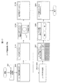
- FIG. 1 is a block diagram illustrating a configuration of a projection display apparatus (hereinafter also referred to as an image display apparatus) according to the first embodiment.
- the detection function unit 101 is a function unit that detects a user's operation.
- the display function unit 151 is a function unit that displays an image in accordance with a user operation, and includes a communication unit 152, an image projection unit 153, and a control unit 154.
- the detection result data 121 is transferred from the detection function unit 101 to the display function unit 151.
- the camera 102 includes an image sensor, a lens, a filter, and the like, and captures an image including a user operation unit (hand or finger).
- the illuminations 103 and 104 include a light emitting diode, a circuit board, a lens, and the like, and irradiate an area captured by the camera 102.
- the lights 103 and 104 may be constantly lit, but the lights 103 and 104 may be lit alternately. Further, when the lighting 103 and 104 is turned on, both may be temporarily turned off, or the lighting 103 and 104 may be blinked at the same timing.
- the illumination light may be invisible light.
- the camera 102 and the illuminations 103 and 104 may be configured by an infrared camera and infrared illumination, and an operation detection process may be performed from the captured infrared image.
- the operation detection unit 105 includes a circuit board, software, and the like, and detects the operation content from the image of the operation article photographed by the camera 102.
- the operation object can be a user's finger or hand or an operation pen.
- an image of a user's characteristic hand is extracted from an image captured by the camera 102 and used for user identification.
- an image of the user's hand is used as the user's feature.
- the user management unit 106 has a circuit board, software, and the like, and registers the features of each user's hand in the database as user data. Further, each user is managed by giving an attribute indicating a user ID and a user operation authority.
- the user identification unit 107 includes a circuit board, software, and the like.
- the operation detection unit 105, the user management unit 106, and the user identification unit 107 described above are portions that detect a user operation and identify a user who operates, and are referred to as a user-specific operation detection unit 110.
- the communication unit 108 includes a network connection, a USB connection, an ultrasonic unit, an infrared communication device, and the like, and is an interface capable of communicating with a device outside the detection function unit 101 such as a display or a projector.
- the control unit 109 includes a circuit board, software, and the like, and controls the camera 102, the illuminations 103 and 104, the operation detection unit 105, the user management unit 106, the user identification unit 107, and the communication unit 108.
- the detection result data 121 is data that the detection function unit 101 outputs to the display function unit 121 via the communication unit 108, and includes information such as the detected operation content, the user ID of the operated user, and the user attribute.
- the display function unit 151 receives the detection result data 121 and displays an image according to an operation with a user's finger or pen.
- the communication unit 152 includes a network connection, a USB connection, an ultrasonic unit, an infrared communication device, and the like, and is an interface that can communicate with components outside the display function unit 151 such as a display and a projector.
- the image projection unit 153 includes a light source lamp, a liquid crystal panel, a lens, and the like, and projects and displays an image on a projection surface.
- the wavelength region of the light projected from the image projection unit 153 does not overlap the wavelength of the illumination light (infrared light) from the illuminations 103 and 104 of the detection function unit 101, the camera (infrared camera)
- the camera infrared camera
- a band pass filter or the like for controlling the wavelength of the projection light may be used.
- the control unit (image processing unit) 154 includes a circuit board, software, and the like, and controls the communication unit 152 and the image projection unit 153.
- the image projected from the image projection unit 153 is processed according to the detection result data 121 sent from the detection function unit 101. That is, whether to accept an operation, the type of video to be displayed, the display format, and the like are determined according to the user ID and user attribute of the operated user as well as the user operation content.
- the video display device shown in FIG. 1 includes the detection function unit 101 and the display function unit 151.
- the detection function unit 101 may be made independent to be an operation detection device.
- the elements 102 to 109 and 152 to 154 are independent, but may be configured with one or a plurality of constituent elements as necessary.
- the elements 105 to 107 may be configured to perform their processing by one or more central processing units (CPUs).
- the elements 102 to 109 are all included in the detection function unit 101, and the elements 152 to 154 are all included in the display function unit 151. You may couple
- the elements 102 to 104 may be configured outside the detection function unit 101.
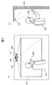
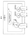
- FIG. 2 is a diagram showing the appearance of the projection display apparatus and the operation state of the user.
- (A) is a front view of the operation state
- (b) is a side view of the operation state.
- the user 251 operates the image projected on the projection plane by the image projection unit 153 using the finger 252.
- the operation surface 201 overlaps at least a part of the image projection surface projected by the image projection unit 153, and the user brings a part of the projected image close to the finger, for example, and touches a certain position.
- the camera 102 images the area of the operation surface 201 and irradiates illumination light from the illuminations 103 and 104 for imaging.
- the image projected by the image projection unit 153 is controlled, and the display format of the image is changed or switched to another image.
- FIG. 2 the user operates with a finger, but the user may perform an operation using an operation tool such as an operation pen or a bar instead of the finger. Or you may operate by not only a finger but the whole hand. Further, FIG. 2 shows a case where there is one user, but it is also possible for a plurality of users to perform operations simultaneously or by switching.
- FIG. 3 is a diagram showing a difference in shadow shape depending on whether or not a finger and an operation surface are in contact.
- (A) and (b) are a front view and a top view when the finger 400 is not in contact with the operation surface 201, and (c) and (d) are views when the fingertip of the finger 400 is in contact with the operation surface 201.
- a front view and a top view in the case of being present are shown.
- a shadow 401 projected by the illumination 104 and a shadow 402 projected by the illumination 103 are formed on both sides of the finger 400, respectively. It will be in a separated state.
- (B) explains the principle of creating a shadow as shown in (a).
- the light emitted by the illumination 104 is blocked by the finger 400, and a shadow 401 is formed on the operation surface 201.
- the light emitted by the illumination 103 is blocked by the finger 400, and a shadow 402 is formed on the operation surface 201. Since the finger 400 is away from the operation surface 201, the shadow 401 and the shadow 402 are separated from each other in the image captured by the camera 101.
- FIG. 4 is a diagram illustrating the relationship between the distance between the finger and the operation surface and the shape of the shadow.
- (A) shows how the shape of the shadow changes depending on the distance between the finger 400 and the operation surface 201.
- the distance between the finger 400 and the operation surface 201 is the shortest (at the time of contact)
- the shadow 401 and the shadow 402 are in the closest state.
- the distance between the shadow 401 and the shadow 402 gradually increases, and the distance between the shadow 401 and the shadow 402 depends on the distance between the finger 400 and the operation surface 201. Therefore, by measuring the distance between the shadow 401 and the shadow 402, the distance between the finger 400 and the operation surface 201 and the contact / non-contact can be determined.
- (B) to (e) indicate at which position of the shadow (called a feature point) the distance between the shadow 401 and the shadow 402 is measured.
- feature points 403 and 404 are set at the tip (fingertip) of the shadow, and the distance between the shadow 401 and the shadow 402 is defined by the distance d between the feature points 403 and 404.
- feature points 403 and 404 are set outside the portion corresponding to the shadow finger, and the distance between the shadow 401 and the shadow 402 is defined by the distance d between the feature points.
- the feature points 403 and 404 are set on the outermost part of the shadow, or on the outer side of the part corresponding to the shadow wrist as shown in (e). The method of setting is also acceptable.
- FIG. 5 is a diagram illustrating processing for detecting a contact point between the finger and the operation surface in the operation detection unit 105.
- A shows a processing flow
- (b) is a figure explaining the process of S507 and S508.
- step S ⁇ b> 501 it is determined whether or not two shadows related to the finger 400 are detected in the image captured by the camera 102. If detected, the process proceeds to S502. In S502, a feature point 403 and a feature point 404 are detected in the two shadows 401 and 402 related to the finger (see FIG. 4). In S503, the distance d between the feature point 403 and the feature point 404 is measured.
- S504 it is determined whether the distance d between the feature point 403 and the feature point 404 is smaller than a predetermined value. If it is smaller than the predetermined value, the process proceeds to S505, and if it is greater than the predetermined value, the process proceeds to S506. In S505, it is determined that the finger 400 is in contact with the operation surface 201, and the process proceeds to S507. In S506, it is determined that the finger 400 is not in contact with the operation surface 201, and the flow ends.
- the tip 541 and the tip 542 are detected in the two shadows 401 and 402 relating to the finger, respectively.
- the midpoint 551 of the tip 541 and the tip 542 is detected as a contact point between the finger 400 and the operation surface 201. Then, the position (coordinates) of the contact point 551 is read, and the process ends.
- the flow returns to S501 to repeat the above flow in order to detect the next contact point.
- the processing in the operation detection unit 105 may use another image processing algorithm for obtaining a similar result.
- FIG. 6 is a diagram showing user registration processing in the user management unit 106.
- the user registration process is a process of registering information (user data) related to a user who operates the operation surface 201 in a database, (a) shows a processing flow, and (b) shows contents of user data to be registered. .
- the user registration process shown here is a case in which the user management unit 106 automatically starts with the detection of a user who is not registered in the database as a trigger.
- the camera 102 captures an image of each user's hand and extracts features relating to the hand.
- Features relating to the hand include the size, shape, color, and the like of the hand, and details will be described with reference to FIG.
- the captured image of the camera 102 can be used for both user operation detection and acquisition of user hand characteristics.
- the extracted features of the user's hand are registered in the database.
- features 600a to 600c regarding the hands of the users A to C are registered as user data.
- an image (outline) of each user's hand is described, but the features of the hand may be digitized or documented as described later.
- the registered user feature is used in a user identification process described later.
- identification information (user ID) is given to the user.
- the user ID assigned here is a user name or a user number for individually identifying the user when there are a plurality of users, and preferably does not overlap.
- the assigned user ID is registered in the database in association with the user feature registered in S602. In the case of automatically assigning a user ID, for example, “user A”, “user B”,...
- an attribute is given to the user.
- the attribute is information for classifying the users according to common characteristics, and here, the users are classified according to the operation authority. For example, an attribute of “special” is given to a user who is permitted all operations, and a “general” attribute is given to a user who is restricted to some operations. In the following, a user with the “special” attribute is called a “special user”, and a user with the “general” attribute is called a “general user”.
- the assigned attribute is registered in the database in association with the user feature registered in S602 or the user ID registered in S603. If it is not necessary to classify users by attribute, S604 may be omitted.
- the attribute can be automatically set according to the usage status of the user. For example, a user who first receives an attribute is a special user, and a user who receives an attribute after the second is a general user. Alternatively, a user whose usage frequency is a certain value or more is a special user, and other users are general users. Alternatively, in consideration of the use in school or the like, a user (teacher) whose hand size is a certain value or more may be a special user, and other users (students) may be general users. Alternatively, after all users are uniformly set as general users, some users may be manually changed to special users.
- a database having user data as shown in FIG. 6B is created. The user data is composed of user characteristics, user IDs and attributes of each user.
- FIG. 7 is a diagram showing examples of parameters representing the features of the user's hand.
- A is the size of the hand
- (b) is the length of the finger
- (c) is the thickness of the finger.
- D is a polygonal approximation of the hand shape, and a plurality of hand feature points are defined and connected.
- E is a polygonal approximation of the shape of the finger, which defines a plurality of finger feature points and connects them.
- F is a blood vessel pattern. Since blood has a high absorption rate of infrared light, a clear blood vessel pattern can be obtained from an image taken by the camera 102, particularly when the infrared light is irradiated from the illuminations 103 and 104. Other parameters such as hand color, hand wrinkle pattern, hand luminance distribution, and nail shape can also be used as hand features.
- the format of user data to be registered in the database may be hand image data, but the above parameters are digitized or documented for ease of use.
- the coordinates of the vertexes of the polygon may be registered.
- one of the above parameters may be registered in the database, or a plurality of parameters may be combined from these parameters.
- FIG. 8 is a diagram showing a manual user registration processing flow.
- the user registration process is started by the user management unit 106 triggered by the user's activation of the user registration mode.
- S802 to S809 in the following processing flow show examples of screens displayed on the operation surface 201.
- the operation detection unit 105 detects the contact point of the user's finger and determines the operation content.
- step S801 the user activates the user registration mode.
- step S802 the user registration is notified.
- the target is displayed and the user's right hand is guided to a predetermined position.
- the camera 102 captures the situation.
- the user management unit 106 extracts features of the user's right hand from the captured image.
- the extracted feature of the right hand of the user is registered in the database (corresponding to S602 in FIG. 6), and notification that the registration of the right hand has been completed is sent.
- the target is displayed and the user's left hand is guided to a predetermined position.
- the camera 102 captures the situation.
- the user management unit 106 extracts the left hand feature of the user from the captured image.
- the extracted feature of the left hand of the user is registered in the database (corresponding to S602 in FIG. 6), and notification that the registration of the left hand has been completed.
- step S807 the user is requested to input a user name.
- the user name input here is registered as a user ID in the database (corresponding to S603 in FIG. 6).
- step S808 the user is requested to select a classification of the user.
- the classification of the user selected here is registered in the database as the attribute of the user (corresponding to S604 in FIG. 6). If there is no need to give an attribute to the user, S808 may be omitted.
- step S809 the user registration is notified. When the notification is completed, the user registration process flow is terminated.
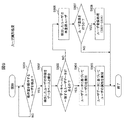
- FIG. 9 is a diagram showing a user identification processing flow in the user identification unit 109.
- step S ⁇ b> 901 it is determined whether a user who operates the operation surface 201 is detected in an image captured by the camera 102. If a user is detected, the process proceeds to S902.
- step S902 features of the user's hand are extracted based on the user image detected in step S901. And it collates with the database of the user management part 106. FIG. At the time of collation, the extracted user characteristics are compared with user data registered in the database. In step S903, it is determined whether there is user data (user feature) that matches the detected user feature in the database as a result of collation. If there is matching user data, the process proceeds to S904, and if not, the process proceeds to S906.
- the user ID of the matched user data is referred to, and the user ID of the detected user is identified. For example, if the detected feature of the user matches the user feature 600a in FIG. 6B, the user ID is “user A”.
- the attribute of the detected user is referred to by referring to the attribute of the matched user data. For example, if the detected feature of the user matches the user feature 600a of FIG. 6B, it can be seen that the attribute of the user is “special”. If no attribute is given to the user (such as when S604 is not performed), S905 may be omitted. When the identification is completed, the identification processing flow ends.
- step S906 it is determined that the detected user is an unregistered user.
- step S907 it is determined whether or not to perform user registration for the detected user. In this case, the user may be instructed. If user registration is to be performed, the process advances to step S908; otherwise, the identification processing flow is terminated.
- the detected user is registered by the above-described user registration process (S601 to S604 in FIG. 6).
- manual user registration processing (S802 to 809 in FIG. 8) may be performed.
- FIG. 10 is a diagram illustrating an example in which different images are projected to different users.
- the image projection unit 151 projects different images (image patterns) 1000a and 1000b so as to be superimposed on the hands of the users A and B.
- the projected video pattern has a unique shape and color that is predetermined for each user ID or attribute.
- a character string may be projected instead of the image.
- the image may not be projected to a specific user (for example, an unregistered user).
- each user confirms whether or not his / her user data (user characteristics, user ID and attribute) is correctly registered in the database. be able to.
- FIG. 11 is a diagram showing an example in which video is displayed in different display formats for different users.
- the drawing trajectories (operation histories) 1100a to 1100c for the drawing operations performed by the users A to C are displayed.
- the trajectory to be displayed has different display formats such as line thickness, color, and type for each user ID and attribute.
- the display format assigned to each user A to C is automatically set on the video display device side.
- FIG. 12 is a diagram showing an example of displaying different menus for different users.
- the menu displayed here is a tool for assisting the user's operation, and corresponds to a display format selection branch or the like.
- different menus 1200a to 1200c are displayed for the users A to C who are performing the operation.
- These menus 1200 include, for example, an interface for changing the thickness, color, and type of a line for displaying a drawing trajectory, an interface for deleting a line once displayed, and the like.
- the menus 1200a to 1200c to be displayed have different items and arrangement for each user ID or for each attribute. Therefore, when the type of operation permitted for each user is different, only the operation items permitted for each user are displayed on the menu. Or you may enable it to set the item and arrangement
- the display position of the menu in the operation surface 201 is preferably displayed close to the user so as to follow the movement of the user.
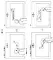
- FIG. 13 is a diagram illustrating an example in which different display processes are performed for different users. Here, the process of deleting what the user once described is taken up.
- (A) is a state in which user A and user B have described the characters 1300a and 1300b, respectively.
- (B) shows the processing when user A performs the delete 1301 operation after the description in (a), only the description 1300a by user A is deleted, and the description 1300b by user B remains without being deleted.
- (c) shows processing when user B performs an erase 1301 operation after the description of (a), only the description 1300b by user B is deleted, and the description 1300a by user A is not deleted. Remaining. That is, the operation (deletion process) performed by each user is applied only to the operation history (description) performed by the user.
- the processing as shown in FIG. 13 can be performed. As a result, even if a plurality of users operate at the same time, the operations of each user do not compete, and the operation history performed by other users is not affected.
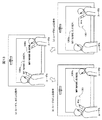
- FIG. 14 is a diagram illustrating an example of restricting operations according to user attributes. Here, an example of adding a restriction to the highly confidential processing X1400 will be described.
- a general user performs an operation for executing the process X1400.
- processing X is restricted to special users only, and processing X is not accepted.
- a message 1402 such as “General user cannot execute the process X” is displayed as shown in FIG.
- ⁇ It is set in advance what kind of operation is allowed for each attribute. As a result, for example, by limiting the processing with high confidentiality and difficulty to special users, accidents such as leakage of confidential information can be prevented.
- FIG. 15 is a diagram illustrating another example in which operations are restricted according to user attributes.
- a plurality of users perform drawing operations at the same time, only a special user drawing operation is accepted and a general user drawing operation is not accepted.
- a message 1500 such as “Only a special user operation is accepted” may be displayed.
- giving the operation authority according to the user attributes can prevent the processing from being confused by a plurality of operations when a large number of users perform the operation simultaneously. For example, when a teacher and a large number of students operate at the same time in a school or the like, this is effective when priority is given to the teacher's operation.
- a user ID or attribute is provisionally assigned based on the user's characteristics and registered. You may treat it like any other user.
- the camera 102 captures the user's hand, and the operation detection unit 105 detects the user's operation.
- the user management unit 106 manages hand features, user IDs, and attributes for each user, and the user identification unit 107 identifies user IDs and attributes from the features of the user's hand.
- the projection-type video display device is stable and easy to use without confusion. Can provide.
- Example 2 a user's hand and face are photographed with a camera for user identification. Then, each user is identified based on the hand and face characteristics, and the video display is controlled.
- Example 2 the configuration of the projection display apparatus is the same as that of Example 1 (FIG. 1).
- the user's hand is photographed by the camera 102, whereas in the second embodiment, the user's hand and face are photographed.
- a plurality of cameras may be prepared, and one of them may photograph a hand and the other with one.
- the number of cameras may be one, and a wide-angle lens or a fisheye lens may be attached to the camera to expand the shooting range so that both hands and faces can be shot.
- the operation detection unit 105 detects the user's operation and extracts an image of the user's hand and face from the image taken by the camera 102 for user identification.
- the user management unit 106 registers the hand and face characteristics of each user in the database as user data.
- the user identification unit 107 compares the hand and face images captured by the camera 102 with user data registered in the database, and identifies the user who is performing the operation.
- Processing for detecting a contact point between the finger and the operation surface in the operation detection unit 105 is the same as that in the first embodiment (FIG. 5).
- the user registration process in the user management unit 106 is performed in the same manner as in the first embodiment (FIG. 6).
- the features of the user's hand and face are taken up as user features.
- FIG. 16 is a diagram illustrating an example of user data managed by the user management unit 106.
- features 600a to 600c relating to the user's hand and features 1600a to 1600c relating to the face of the user are extracted based on the images of the hands and faces of the users A to C photographed by the camera 102 and registered in the database.
- the parameters representing the features of the user's hand are as described in the first embodiment (FIG. 7).
- the parameters representing the facial features 1600a to 1600c to be added include the relative positions and sizes of facial parts, facial contours, facial colors, eyes, nose, mouth, and chin shapes.
- the features related to the user's hand and face registered in the database are used in the user identification process.
- the user registration process can be performed either manually or automatically, but may be selected according to the environment in which the video display device is used or the user's preference.
- the user 251 when the user 251 operates the operation surface 201, the user's hand always exists within the shooting range of the camera 102.
- the user's face is not necessarily within the shooting range of the camera 102 depending on the user's standing position and the direction in which the camera is directed. Therefore, when registering the facial features of the user, the registration process must be performed after waiting for the user's face to fall within the shooting range. In such a case, the user's face should be registered manually.
- FIG. 17 is a diagram showing a manual user registration processing flow.
- the manual user registration process is triggered by the user's activation of the user registration mode.
- the face registration process of S1701-1703 is added to the hand registration process of S801-809 described in the first embodiment (FIG. 8).
- the position to be added is, for example, between S802 and S803.
- the user's hand registration process may be performed with only one hand.
- S1701 to S1703 represent screens displayed on the operation surface 201, and the user performs an operation for user registration processing according to the projection screen.
- step S1701 the user is notified to view the camera.
- step S1702 a camera image 1711 being captured by the camera 102 is displayed, and the user's face is guided to a predetermined position.
- the camera 102 captures the user's face.
- step S1703 notification that the face registration is completed is sent.
- the user's hand characteristics are registered in S803 to S806, and in S807 and S808, the user ID and attributes are assigned to the user's hand and face characteristics to complete the user registration.
- User identification processing in the user identification unit 107 is the same as that in the first embodiment (FIG. 9). However, in S902 (user feature verification), the detected hand feature and facial feature are combined, and the hand and facial features registered in the database are compared. The use of both hand and face features for matching reduces the probability of matching errors and has the effect of further improving the reliability of the identification process.
- the user's face being operated does not necessarily exist within the shooting range of the camera 102. If the user's face cannot be photographed, collation may be performed using only the hand feature, and if the user's face can be photographed, collation may be performed using both the hand feature and the facial feature.
- the second embodiment it is possible to provide a stable and easy-to-use video display device without confusion in control even when a plurality of users are used simultaneously or after replacement.
- the user's hand feature and the facial feature are used in combination, the user identification accuracy is improved and the reliability of the apparatus can be further improved.
- Example 3 a user's hand and a wearable terminal worn by the user are photographed with a camera for user identification. And each user is identified based on the characteristic of a hand and a wearable terminal, and video display is controlled.
- the wearable terminal is a terminal that can be worn on the body such as a user's finger, wrist, head, etc.
- a general wearing tool such as a ring, a wristwatch, and glasses, or only an outer shape has the shape of the wearing tool. It may be a thing.
- the wearable terminal may have a communication function.
- the wearable terminal worn by the user may be owned by each user or may be assigned to each user for the operation of the video display device.
- the configuration of the projection display apparatus is the same as that of the first embodiment (FIG. 1).
- the user's hand and wearable terminal are photographed by the camera 102. If it is difficult to shoot both hands and wearable terminals with one camera, prepare multiple cameras, and use one of them to shoot your hand and the other to shoot your wearable terminal. Good.
- the number of cameras may be one, and a wide-angle lens or a fisheye lens may be attached to the camera to expand the shooting range so that both hands and wearable terminals can be shot.
- the operation detection unit 105 detects the user's operation and extracts the user's hand and the wearable terminal image from the image taken by the camera 102 for user identification.
- the user management unit 106 registers the hand of each user and the characteristics of the wearable terminal in the database as user data.
- the user identifying unit 107 collates the hand and wearable terminal image captured by the camera 102 with user data registered in the database, and identifies the user who is performing the operation.
- Processing for detecting a contact point between the finger and the operation surface in the operation detection unit 105 is the same as that in the first embodiment (FIG. 5).
- the user registration process in the user management unit 106 is performed in the same manner as in the first embodiment (FIG. 6).
- the user's hand and the wearable terminal features are registered as user features.
- FIG. 18 is a diagram illustrating an example of user data managed by the user management unit 106.
- features 600a to 600c relating to the user's hand and features 1800a to 1800c relating to the wearable terminal are extracted based on the images of the hands of the users A to C and the wearable terminals (here, wristwatches) captured by the camera 102. And register it in the database.
- the parameters representing the features of the user's hand are as described in the first embodiment (FIG. 7).
- the parameters representing the wearable terminal features 1800a to 1800c to be added include the size, shape, color, etc. of the terminal (watch).
- the features related to the user's hand and face registered in the database are used in the user identification process.
- the user registration process can be performed either manually or automatically, but may be selected according to the environment in which the video display device is used or the user's preference. Hereinafter, manual user registration processing will be described.
- the manual user registration process is the same as that of the first embodiment (FIG. 8) when the wearable terminal is worn on the hand. It is assumed that each user wears a wearable terminal on his / her right hand or left hand. In step S803 if the user wears the right hand, and in step S805 if the user wears the left hand, the user's hand and the wearable terminal are also photographed to extract the hand features and wearable terminal features as user features. Register in the database.
- step S1702 the processing of the second embodiment (FIG. 17) may be applied. That is, in step S1702, the user's face may be photographed, and the wearable terminal (glasses) portion may be extracted from the image.
- User identification processing in the user identification unit 107 is the same as that in the first embodiment (FIG. 9). However, in S902 (user feature collation), the detected features of the user's hand and the features of the wearable terminal are combined, and the features registered in the database and the features of the wearable terminal are compared. By using the characteristics of both the hand and the wearable terminal at the time of collation, the probability of collation error is reduced, and the reliability of the identification process is further improved.
- the collation is performed using only the hand features, and if the wearable terminal can be shot, You may make it collate using both the characteristic and the characteristic of a wearable terminal.
- the collation is performed using a wearable terminal having a feature in shape and color
- the user identification function is improved as compared with the case of using a hand or face.
- the wearable terminal has a communication function
- the user can be identified using the communication function.
- the detection function unit 101 communicates with the wearable terminal in advance via the communication unit 108 and acquires terminal ID information that can identify the terminal from each wearable terminal.
- the user management unit 106 registers the acquired terminal ID information in the database together with the user ID (see FIG. 18).
- the user identification unit 107 is registered in the database based on not only the characteristics of the wearable terminal worn by the user extracted from the camera image, but also the terminal ID information acquired by the detection function unit 101 communicating with the wearable terminal.
- the user is identified by collating with user data (characteristics of wearable terminal and terminal ID information). By using the terminal ID information, the accuracy of user identification is further improved.
- the third embodiment it is possible to provide a stable and easy-to-use video display device without confusion of control even when a plurality of users are used at the same time or in exchange.
- the features of the user's hand and the features of the wearable terminal to be worn are used in combination, the identification accuracy of the user is improved and the reliability of the apparatus can be further increased.
- Example 4 describes user identification when a user uses an operation pen for operation.
- each user is identified based on whether or not the hand is holding a pen and video display is controlled.
- the structure of the pen for operation is not particularly limited, but may be one that emits light upon contact as described later. Moreover, it is not necessary to distinguish the pen to be used for each user.
- Example 4 the configuration of the projection display apparatus is the same as that of Example 1 (FIG. 1).
- the user's hand is photographed by the camera 102, and when the user's hand is holding the pen, the pen is also photographed.
- the operation detection unit 105 detects the user's operation and extracts the image of the user's hand and pen from the image taken by the camera 102 for user identification.
- the user management unit 106 registers the features of each user's hand and the presence or absence of a pen in the database as user data.
- the user identification unit 107 compares the hand and pen images taken by the camera 102 with user data registered in the database, and identifies the user who is performing the operation.
- the operation detection unit 105 performs processing for detecting a contact point between the pen and the operation surface.
- maintain a pen contacts an operation surface with a finger it is the same as that of Example 1 (FIG. 5).
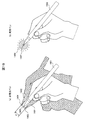
- FIG. 19 is a diagram illustrating processing for detecting a contact point between the pen and the operation surface.
- the pens to be used will be described separately for a type in which the tip does not emit light when contacting the surface (non-light emitting pen) and a type that emits light when contacting the surface (light emitting pen or electronic pen).
- FIG. 1 shows a state in which the camera 1102 shoots a pen 1951 whose tip does not emit light when contacting the surface.
- a shadow 1901 due to the illumination 104 and a shadow 1902 due to the illumination 103 are generated on both sides of the pen 1951.
- the distance between the two shadows 1901 and 1902 decreases as the pen 1951 approaches the operation surface 201.
- feature points 1903 and 1904 are set at the tips of the respective shadows, and the distances of the shadows 1901 and 1902 are defined by the distance d between the feature points.
- the distance d between the feature points is smaller than a predetermined value, it is determined that the tip of the pen 1951 is in contact with the operation surface 201. At this time, a midpoint 1905 of the feature points 1903 and 1904 is detected as a contact point between the pen 1951 and the operation surface 201.
- the light-emitting pen 1952 includes a pressure-sensitive sensor, a light-emitting element, a circuit board, and the like, and detects whether or not the tip is in contact with the surface by the pressure-sensitive sensor.
- the light emitting element is turned on, and when it is not in contact, the light emitting element is turned off.
- a light emitting area 1906 is formed at the tip. At this time, the center position of the light emitting area 1906 is detected as a contact point 1907 between the light emitting pen 1952 and the operation surface 201.
- the processing in the operation detection unit 105 may use another image processing algorithm for obtaining a similar result.
- the user registration processing in the user management unit 106 is performed in the same manner as in the first embodiment (FIG. 6) except for S604. However, in the attribute assignment in S604, a case where setting is performed based on the presence or absence of a pen will be described.
- FIG. 20 is a diagram illustrating an example of user data managed by the user management unit 106.
- attributes such as “special” or “general” are fixedly given to each user.
- Example 4 the attribute for each user is not fixed, but the attribute is determined according to the situation.
- an attribute determination rule for that purpose here, when the user is holding the pen, it is treated as “special user”, and when the user is not holding the pen, it is treated as “general user”.
- the user registration process can be either manual or automatic, but any one may be selected according to the environment in which the video display device is used and the user's preference.
- the attribute determination process (S808) in the first embodiment (FIG. 8) is not selected by the user, but is automatically determined based on the presence or absence of a pen from the user image.
- User identification processing in the user identification unit 107 is the same as that in the first embodiment (FIG. 9). However, in S905 (attribute identification), the attribute is identified in accordance with the user attribute determination rule registered in the user data of FIG. That is, the user is identified as a special user when the pen is held, and as a general user when the pen is not held.
- the user is identified from the characteristics of the user's hand, and the attribute is identified based on whether or not the user is holding the pen. Since the user holding the pen is treated as a special user, the operation priority is higher than that of a general user not holding the pen. Therefore, the special user who gives priority to the operation can be easily changed by changing the pen user among a plurality of users.
- the fourth embodiment it is possible to provide a stable and easy-to-use video display device without confusion in control even when a plurality of users are used at the same time or in exchange.
- the fourth embodiment when the user operates using the pen, the setting of the user prioritizing the operation can be easily changed, and the usability is further improved.
- 101 Function detection unit (operation detection device), 102: Camera (imaging unit), 103, 104: lighting, 105: Operation detection unit, 106: User management unit, 107: a user identification unit, 108: Communication unit 109: Control unit, 110: User-specific operation detection unit, 121: detection result data, 151: Display function unit, 152: Communication unit, 153: image projection unit, 154: Control unit (video processing unit), 201: operation surface, 251: user, 252,400: finger, 401, 402: shadow, 403, 404: feature points, 551: contact point, 600, 1600: user characteristics, 1800: Wearable terminal, 1951, 1952: pens for operation.
Landscapes
- Engineering & Computer Science (AREA)
- General Engineering & Computer Science (AREA)
- Theoretical Computer Science (AREA)
- Human Computer Interaction (AREA)
- Physics & Mathematics (AREA)
- General Physics & Mathematics (AREA)
- User Interface Of Digital Computer (AREA)
Abstract
本発明は、操作するユーザを識別するとともに、ユーザに応じて処理内容を切り替えることが可能な投写型映像表示装置を提供する。投写型映像表示装置は、投写面の映像投写領域を撮像する撮像部102と、撮像部により撮像した画像に基づいて、映像表示に対するユーザの操作内容を検出する操作検出部105と、撮像部により撮像した画像に基づいて、操作を行ったユーザを識別するユーザ識別部107と、ユーザの操作内容とユーザの識別結果に応じて、投写面に表示する映像の処理を行う映像処理部154と、映像処理部にて処理した映像を投写面に投写する映像投写部153と、を備える。
Description
本発明は、ユーザの操作を検出しこれに応じて映像表示を行う投写型映像表示装置と映像表示方法、及びこれに用いる操作検出装置に関する。
投写型映像表示装置(プロジェクタ)の投写面上でのユーザ操作入力として、タッチセンサ等の特殊なデバイスを用いることなく、ユーザの操作部(指)を撮影して操作内容を検出する技術が提案されている。
特許文献1には、照明手段により照らされた状態で操作者を撮像手段に撮像させる手段と、前記撮像手段により得られる操作者の画像データをもとに、前記操作者の特定部位の領域を検出する手段と、前記検出された操作者の特定部位の領域から影の部分を抽出する手段と、前記抽出された影の部分の中から、エッジが直線を成す線分を複数検出し、検出された線分同士が鋭角に交わる点を検出し、この交点を前記操作者の特定部位の領域内における指差し位置として検出する手段と、を具備する操作検出装置が記載されている。
また、特許文献2には、スクリーンに映像を投写する投写部と、少なくとも前記スクリーンに投写された映像を含む領域を撮像するための撮像部と、前記撮像部により撮像された画像から、前記スクリーン上方を移動する所定物体の実像を検出する実像検出部と、前記撮像部により撮像された画像から、前記投写部からの投写光により生じる前記所定物体の影を検出する影検出部と、前記所定物体の実像と影の対応点間の距離が所定のしきい値以下である場合、前記所定物体が前記スクリーンに接触していると判定する接触判定部と、前記接触判定部により接触していると判定されたとき、前記所定物体の座標を前記映像に対するポインティング位置として出力する座標決定部と、を備える投写型映像表示装置が記載されている。
従来の投写型映像表示装置において、ユーザの操作を撮影画像により検出して映像表示を制御することができるが、複数のユーザが操作する場合、どのユーザが操作しても同様の処理を行うものとなる。よって、複数のユーザが同時に異なる操作を行う場合、複数の処理が競合して各ユーザに対する正常な処理が困難となることがある。あるいは、複数のユーザが入れ替わって操作する場合にも、ユーザごとに異なる処理を頻繁に行うと安定な処理が困難となることがある。
特許文献1では、操作者の画像データから影の部分を抽出し、影の線分が鋭角に交わる点を指差し位置として検出している。さらに、線分同士が成す鋭角の二等分線を求め、この二等分線が操作者の特定部位の輪郭と交わる位置を検出し、検出された位置に基づいて指差し動作が操作者により行われたか操作者以外により行われたかを判定している。しかしながら、操作者が誰であるかを検出し、操作者に応じて処理内容を切り替えることは考慮されていない。すなわち、複数の操作者が同時に、あるいは入れ替わって操作する場合、操作者を区別して映像表示の処理を行うことはできない。
特許文献2では、所定物体(指)の実像と影の対応点間の距離が所定のしきい値以下である場合、所定物体がスクリーンに接触していると判定している。この場合にも、操作者が誰であるかを検出し、操作者に応じて処理内容を切り替えることは考慮されていない。
本発明の目的は、操作するユーザを識別するとともに、ユーザに応じて処理内容を切り替えることが可能な投写型映像表示装置と映像表示方法、及びこれに用いる操作検出装置を提供することである。
本発明は上記課題を解決するために、複数の手段を含んでいる。その一例を挙げるならば、投写面に映像を投写して表示する投写型映像表示装置において、投写面の映像投写領域を撮像する撮像部と、撮像部により撮像した画像に基づいて、映像表示に対するユーザの操作内容を検出する操作検出部と、撮像部により撮像した画像に基づいて、操作を行ったユーザを識別するユーザ識別部と、ユーザの操作内容とユーザの識別結果に応じて、投写面に表示する映像の処理を行う映像処理部と、映像処理部にて処理した映像を投写面に投写する映像投写部と、を備える。
あるいは、投写面に映像を投写して表示する映像表示方法において、投写面の映像投写領域を撮像する撮像ステップと、撮像ステップにより撮像した画像に基づいて、映像表示に対するユーザの操作内容を検出する操作検出ステップと、撮像ステップにより撮像した画像に基づいて、操作を行ったユーザを識別するユーザ識別ステップと、ユーザの操作内容とユーザの識別結果に応じて、投写面に表示する映像の処理を行う映像処理ステップと、を備える。
本発明によれば、操作するユーザを識別するとともに、ユーザに応じて処理内容を切り替えることにより、複数のユーザが同時に、あるいは入れ替わって操作した場合にも、投写型映像表示装置の処理が安定しユーザの使い勝手が向上する。
以下、本発明の実施例を図面を用いて説明する。
実施例1では、カメラでユーザの手を撮像し、操作するユーザを識別しながらユーザの操作を検出する方法について説明する。そのため、予め各ユーザの手の特徴を取得しておき、各ユーザに対するユーザIDと属性を付与し、各ユーザのユーザIDと属性に応じて操作に従った映像表示の処理を行う。ここにユーザIDとはユーザを識別するための情報で、属性とはユーザを操作権限に応じて分類し、操作権限に応じて付与する情報である。
図1は、実施例1における投写型映像表示装置(以下、映像表示装置ともいう)の構成を示すブロック図である。検出機能部101はユーザの操作を検出する機能部で、カメラ(撮像部)102、2つの照明103,104、操作検出部105、ユーザ管理部106、ユーザ識別部107、通信部108、制御部109を含む。表示機能部151はユーザの操作に応じて映像表示を行う機能部で、通信部152、映像投写部153、制御部154を含む。検出機能部101から表示機能部151へは、検出結果データ121を転送する。
まず、検出機能部101の各構成要素を説明する。
カメラ102は、イメージセンサ、レンズ、フィルタ等を有し、ユーザの操作部(手や指)を含む画像を撮影する。照明103及び104は、発光ダイオード、回路基板、レンズ等を有し、カメラ102が撮影する領域を照射する。照明103、104は常時点灯させてもよいが、照明103と104を交互に点灯させてもよい。さらに、照明103と104の点灯が切り替わる際に一時的に両者を消灯させる、あるいは、照明103と104を同じタイミングで点滅させてもよい。照明光は不可視光であっても良く、例えばカメラ102、照明103、104を、赤外カメラと赤外照明で構成し、撮影した赤外画像から操作検出の処理を行ってもよい。その場合には、赤外カメラにフィルタを追加し、赤外領域でない光を一部あるいは全て遮蔽して撮影するとよい。すなわち、照明103、104からの照明光の波長領域を、表示機能部151(映像投写部153)にて投写する光の波長領域と分離することで、ユーザは照明光を視認することなく投写映像を視聴できる。
カメラ102は、イメージセンサ、レンズ、フィルタ等を有し、ユーザの操作部(手や指)を含む画像を撮影する。照明103及び104は、発光ダイオード、回路基板、レンズ等を有し、カメラ102が撮影する領域を照射する。照明103、104は常時点灯させてもよいが、照明103と104を交互に点灯させてもよい。さらに、照明103と104の点灯が切り替わる際に一時的に両者を消灯させる、あるいは、照明103と104を同じタイミングで点滅させてもよい。照明光は不可視光であっても良く、例えばカメラ102、照明103、104を、赤外カメラと赤外照明で構成し、撮影した赤外画像から操作検出の処理を行ってもよい。その場合には、赤外カメラにフィルタを追加し、赤外領域でない光を一部あるいは全て遮蔽して撮影するとよい。すなわち、照明103、104からの照明光の波長領域を、表示機能部151(映像投写部153)にて投写する光の波長領域と分離することで、ユーザは照明光を視認することなく投写映像を視聴できる。
操作検出部105は、回路基板やソフトウェア等を有し、カメラ102で撮影した操作物の画像から操作内容を検出する。操作物として、ユーザの指や手、あるいは操作用ペンが可能である。また、カメラ102で撮影した画像からユーザの特徴手の画像を抽出し、ユーザの識別に用いる。本実施例では、ユーザの特徴としてユーザの手の画像を使用する。
ユーザ管理部106は、回路基板やソフトウェア等を有し、各ユーザの手の特徴をユーザデータとしてデータベースに登録する。さらに、各ユーザに対しユーザIDとユーザの操作権限を示す属性を付与して管理する。
ユーザ識別部107は、回路基板やソフトウェア等を有し、カメラ102で撮影した手の画像とユーザ管理部107のデータベースに登録されているユーザデータを照合し、操作を行っているユーザのユーザIDと属性を識別する。
上記した操作検出部105、ユーザ管理部106、ユーザ識別部107は、ユーザの操作を検出するとともに操作するユーザを識別する部分で、ユーザ別操作検出部110と呼ぶ。
上記した操作検出部105、ユーザ管理部106、ユーザ識別部107は、ユーザの操作を検出するとともに操作するユーザを識別する部分で、ユーザ別操作検出部110と呼ぶ。
通信部108は、ネットワーク接続やUSB接続、超音波ユニット、赤外線通信装置等を有し、ディスプレイやプロジェクタ等、検出機能部101の外部にある装置と通信できるインタフェースである。
制御部109は、回路基板やソフトウェア等を有し、カメラ102、照明103、104、操作検出部105、ユーザ管理部106、ユーザ識別部107、通信部108を制御する。
検出結果データ121は、検出機能部101が通信部108を介して表示機能部121に出力するデータであり、検出した操作内容、操作したユーザのユーザID、ユーザの属性等の情報が含まれる。
次に、表示機能部151の各構成要素を説明する。表示機能部151は、検出結果データ121を受け、ユーザの指やペンによる操作に応じて映像表示を行う。
通信部152は、ネットワーク接続やUSB接続、超音波ユニット、赤外線通信装置等を有し、ディスプレイやプロジェクタ等、表示機能部151の外部にある構成要素と通信できるインタフェースである。
映像投写部153は、光源ランプ、液晶パネル、レンズ等を有し、投写面に映像を投写し表示させる。ここで、映像投写部153より投写する光の波長領域を、検出機能部101の照明103、104からの照明光(赤外光)の波長と重ならないようにすれば、カメラ(赤外カメラ)102で撮影するユーザの操作画像に影響を与えることはない。そのために、投写光の波長を制御する帯域通過フィルタ等を用いてもよい。
制御部(映像処理部)154は、回路基板やソフトウェア等を有し、通信部152、映像投写部153を制御する。特に、検出機能部101から送られる検出結果データ121に応じて、映像投写部153から投写する映像の処理を行う。すなわち、ユーザの操作内容だけでなく、操作したユーザのユーザIDやユーザの属性に応じて、操作を受け付けるか否か、表示する映像の種類や表示形式などを決定する。
図1に示す映像表示装置は、検出機能部101と表示機能部151を含む構成としたが、検出機能部101を独立させで操作検出装置としてもよい。各要素102~109、152~154は独立しているが、必要に応じて1または複数の構成要件で構成してもよい。例えば、要素105~107は1または複数の中央処理装置(CPU)でその処理を行うように構成してもよい。また、要素102~109を全て検出機能部101の内部に、要素152~154を全て表示機能部151の内部に有しているが、1または複数の構成要素を外部に有し、ネットワーク接続やユニバーサルシリアルバス(USB)接続によって結合してもよい。例えば、要素102~104を検出機能部101の外部に構成してもよい。
図2は、投写型映像表示装置の外観及びユーザの操作状態を示す図である。(a)は操作状態の正面図、(b)は操作状態の側面図である。映像投写部153が投写面に投写する映像を、ユーザ251は指252を用いて操作する。操作面201は、映像投写部153が投写する映像投写面と少なくもその一部が重なっており、ユーザは投写された映像の一部に、例えば指を接近させ、またある位置に接触することにより、所望の操作指示を行う。カメラ102は操作面201の領域を撮像し、また撮像のために照明103、104から照明光を照射する。ユーザの操作指示に応じて、映像投写部153が投写する映像は制御され、映像の表示形式が変更されたり、他の映像に切り替えられたりする。
図2ではユーザは指で操作を行っているが、指の代わりに操作用ペンや差し棒等の操作具を使って操作を行ってもよい。あるいは指のみでなく、手全体で操作を行ってもよい。また、図2ではユーザが1人の場合を示しているが、複数のユーザが同時に、あるいは入れ替わって操作を行うことも可能である。
図3は、指と操作面の接触/非接触による影の形状の違いを示す図である。(a)と(b)は、指400が操作面201に接触していない場合の正面図と上面図を、(c)と(d)は、指400の指先が操作面201に接触している場合の正面図と上面図を示す。
(a)に示すように非接触の場合は、指400の両側にそれぞれ、照明104によって投影される影401と、照明103によって投影される影402とができ、影401と影402はそれぞれが離れた状態となる。(b)は、(a)に示すような影ができる原理を説明している。指400の先端の方向から見た場合、照明104が照射する光が指400で遮断され、操作面201上に影401ができる。また、照明103が照射する光が指400で遮断され、操作面201上に影402ができる。指400が操作面201から離れているので、カメラ101が撮影する画像では、影401と影402は互いに離れた状態となる。
次に、(c)に示すように接触している場合は、影401と影402は接近した状態となる。(d)は、(c)に示すような影ができる原理を説明している。指400の先端の方向から見た場合、照明104が照射する光により影401ができ、照明103が照射する光により影402ができる。指400は操作面201に接触しているので、カメラ102が撮影する画像では、影401と影402は接近した状態となる。
図4は、指と操作面との距離と影の形状の関係を示す図である。
(a)は、指400と操作面201との距離によって影の形状が変化する様子を示す。指400と操作面201との距離が最も小さい場合(接触時)には、影401と影402は最も接近した状態となる。指400と操作面201が離れると、影401と影402との距離は次第に大きくなり、影401と影402との距離は指400と操作面201との距離に依存する。よって、影401と影402との距離を測定することで、指400と操作面201の距離や接触/非接触を判定できる。
(a)は、指400と操作面201との距離によって影の形状が変化する様子を示す。指400と操作面201との距離が最も小さい場合(接触時)には、影401と影402は最も接近した状態となる。指400と操作面201が離れると、影401と影402との距離は次第に大きくなり、影401と影402との距離は指400と操作面201との距離に依存する。よって、影401と影402との距離を測定することで、指400と操作面201の距離や接触/非接触を判定できる。
(b)~(e)は、影401と影402との距離を、影のどの位置(特徴点と呼ぶ)で測定するかを示している。(b)では、影の先端(指先)に特徴点403と404を設定し、影401と影402との距離を特徴点403と404間の距離dで定義する。(c)では、影の指に相当する部分の外側に特徴点403と404を設定し、特徴点間の距離dで影401と影402との距離を定義する。あるいは(d)のように、影の最も外側に位置する部分に特徴点403と404を設定する方法や、(e)のように、影の手首に相当する部分の外側に特徴点403と404を設定する方法でもよい。
次に、ユーザ別操作検出部110内の、操作検出部105、ユーザ管理部106及びユーザ識別部107の処理について詳しく説明する。
図5は、操作検出部105における指と操作面の接触点を検出する処理を示す図である。(a)は処理フローを示し、(b)はS507とS508の工程を説明する図である。
S501では、カメラ102によって撮影される画像において、指400に関する2つの影が検出されているか否かを判定する。検出したらS502へ進む。
S502では、指に関する2つの影401,402において、それぞれ特徴点403と特徴点404を検出する(図4参照)。
S503では、特徴点403と特徴点404との距離dを測定する。
S502では、指に関する2つの影401,402において、それぞれ特徴点403と特徴点404を検出する(図4参照)。
S503では、特徴点403と特徴点404との距離dを測定する。
S504では、特徴点403と特徴点404との距離dが所定の値より小さいか否かを判定する。所定の値よりも小さい場合はS505に進み、所定の値以上である場合はS506に進む。
S505では、指400が操作面201に接触していると判定し、S507に進む。
S506では、指400が操作面201に接触していないと判定し、フローを終了する。
S505では、指400が操作面201に接触していると判定し、S507に進む。
S506では、指400が操作面201に接触していないと判定し、フローを終了する。
S507では、図5(b)に示すように、指に関する2つの影401,402において、それぞれ先端541と先端542を検出する。
S508では、図5(b)に示すように、先端541と先端542の中点551を指400と操作面201との接触点として検出する。そして、接触点551の位置(座標)を読み取り、処理を終了する。
S508では、図5(b)に示すように、先端541と先端542の中点551を指400と操作面201との接触点として検出する。そして、接触点551の位置(座標)を読み取り、処理を終了する。
なお、上記フローが一巡して終了しても、ユーザが操作継続中であれば次の接触点を検出するために、S501に戻り上記フローを繰り返して行う。
また、操作検出部105における処理は、同様の結果を得るための他の画像処理のアルゴリズムを用いてもよい。
また、操作検出部105における処理は、同様の結果を得るための他の画像処理のアルゴリズムを用いてもよい。
図6は、ユーザ管理部106におけるユーザ登録処理を示す図である。ユーザ登録処理とは、操作面201を操作するユーザに関連した情報(ユーザデータ)をデータベースに登録する処理であり、(a)は処理フローを、(b)は登録するユーザデータの内容を示す。ここに示すユーザ登録処理は、データベースに登録のないユーザが検出されたことをトリガとして、ユーザ管理部106により自動的に開始される場合である。
S601では、カメラ102により各ユーザの手の画像を撮影し、手に関する特徴を抽出する。手に関する特徴としては手の大きさ、形状、色等が挙げられ、詳細は図7で説明する。図2に示したように、ユーザ251が操作面201を操作する場合にはユーザの手が必ずカメラ102の撮影範囲内に存在することになり、撮影した画像からユーザの手の特徴を抽出することができる。すなわち、カメラ102の撮影画像は、ユーザの操作検出とユーザの手の特徴の取得の両方に用いることができる。
S602では、抽出したユーザの手の特徴をデータベースに登録する。図6(b)に示すように、ユーザデータとして、各ユーザA~Cの手に関する特徴600a~600cが登録される。ここでは各ユーザの手の画像(輪郭)を記載しているが、後述するように手の特徴を数値化あるいは文書化したものでもよい。登録されたユーザ特徴は、後述するユーザ識別処理において利用される。
S603では、ユーザに対して識別情報(ユーザID)を付与する。ここで付与するユーザIDは、複数のユーザが存在する場合において、ユーザを個々に識別するためのユーザ名やユーザ番号であり、重複しないことが好ましい。付与したユーザIDは、S602で登録したユーザ特徴と関連づけてデータベースに登録する。ユーザIDを自動的に付与する場合は、例えば「ユーザA」、「ユーザB」・・・のように、順に機械的に付与すればよい。
S604では、ユーザに対して属性を付与する。属性とは、ユーザを共通する性質により分類するための情報であり、ここでは操作権限に対応してユーザを分類する。例えば、すべての操作が許可されるユーザには「特別」、一部の操作が制限されるユーザには「一般」の属性を付与する。以下では、「特別」の属性が付与されたユーザを「特別ユーザ」、「一般」の属性が付与されたユーザを「一般ユーザ」と呼ぶ。付与した属性は、S602で登録したユーザ特徴、あるいはS603で登録したユーザIDと関連付けてデータベースに登録する。ユーザを属性で分類する必要がない場合には、S604は省略してもよい。
属性の付与に関しては、ユーザの使用状況に応じて自動的に設定することができる。例えば、最初に属性の付与を受けるユーザは特別ユーザ、2番目以降に属性の付与を受けるユーザは一般ユーザとする。または、使用頻度がある一定値以上のユーザは特別ユーザ、それ以外のユーザは一般ユーザとする。あるいは、学校等での用途を考慮し、手の大きさがある一定値以上のユーザ(教師)は特別ユーザ、それ以外のユーザ(生徒)は一般ユーザとしてもよい。あるいは、すべてのユーザを一律に一般ユーザに仮設定した後、手動により一部のユーザについて特別ユーザに変更してもよい。
以上の処理によって、図6(b)に示すようなユーザデータを有するデータベースが作成される。ユーザデータは、各ユーザのユーザ特徴、ユーザID及び属性で構成される。
以上の処理によって、図6(b)に示すようなユーザデータを有するデータベースが作成される。ユーザデータは、各ユーザのユーザ特徴、ユーザID及び属性で構成される。
図7は、ユーザの手の特徴を表すパラメータの例を示す図である。(a)は手の大きさ、(b)は指の長さ、(c)は指の太さをパラメータとしている。(d)は手の形状を多角形近似したもので、手の特徴点を複数定めそれらを結んでいる。(e)は指の形状を多角形近似したもので、指の特徴点を複数定め、それらを結んでいる。(f)は血管パターンである。血液は赤外光の吸収率が高いことから、特に照明103、104から赤外光を照射すると、カメラ102で撮影した画像から鮮明な血管パターンを取得することができる。これ以外のパラメータとして、手の色、手のしわのパターン、手の輝度分布、爪の形状等も手の特徴として利用できる。
データベースに登録するユーザデータの形式は、手の画像データでもよいが、上記パラメータを数値化あるいは文書化したものが使いやすい。例えば、(d)の手の形状については、多角形の頂点の座標を登録すればよい。また、データベースに登録するのは、上記パラメータのうちの1つであってもよいし、これらの中から複数のパラメータを組み合わせてもよい。
図8は、手動によるユーザ登録処理フローを示す図である。この場合、ユーザがユーザ登録モードを起動したことをトリガとして、ユーザ管理部106によりユーザ登録処理が開始される。また、以下の処理フロー中のS802~S809では、操作面201に表示される画面例を示す。ユーザが手動により登録処理を行う際にも、操作検出部105はユーザの指の接触点を検出して、操作内容を判定する。
S801では、ユーザはユーザ登録モードを起動する。
S802では、ユーザ登録を開始する旨を通知する。
S802では、ユーザ登録を開始する旨を通知する。
S803では、ターゲットを表示し、ユーザの右手を所定の位置に誘導する。ユーザは所定の位置に右手を移動させると、その様子をカメラ102で撮影する。ユーザ管理部106は、撮影した画像からユーザの右手の特徴を抽出する。
S804では、抽出したユーザの右手の特徴をデータベースに登録し(図6のS602に相当)、右手の登録が完了した旨を通知する。
S804では、抽出したユーザの右手の特徴をデータベースに登録し(図6のS602に相当)、右手の登録が完了した旨を通知する。
S805では、ターゲットを表示し、ユーザの左手を所定の位置に誘導する。ユーザは所定の位置に左手を移動させると、その様子をカメラ102で撮影する。ユーザ管理部106は、撮影した画像からユーザの左手の特徴を抽出する。
S806では、抽出したユーザの左手の特徴をデータベースに登録し(図6のS602に相当)、左手の登録が完了した旨を通知する。
S806では、抽出したユーザの左手の特徴をデータベースに登録し(図6のS602に相当)、左手の登録が完了した旨を通知する。
S807では、ユーザに対して、ユーザ名の入力を求める。ここで入力されたユーザ名は、ユーザIDとしてデータベースに登録する(図6のS603に相当)。
S808では、ユーザに対して、ユーザの分類の選択を求める。ここで選択されたユーザの分類は、該ユーザの属性としてデータベースに登録する(図6のS604に相当)。ユーザに属性を付与する必要がない場合には、S808を省略してもよい。
S809では、ユーザ登録が完了した旨を通知する。通知が完了したら、ユーザ登録処理フローを終了する。
S808では、ユーザに対して、ユーザの分類の選択を求める。ここで選択されたユーザの分類は、該ユーザの属性としてデータベースに登録する(図6のS604に相当)。ユーザに属性を付与する必要がない場合には、S808を省略してもよい。
S809では、ユーザ登録が完了した旨を通知する。通知が完了したら、ユーザ登録処理フローを終了する。
なお、上記フローが一巡して終了しても、他のユーザ登録を継続して行う場合は、S801に戻り上記フローを繰り返して行う。また、データベースに登録済みのユーザが再度ユーザ登録を試みた場合に、ユーザデータの重複を避けるために、途中でフローを抜けるルートを設けてもよい。また、ユーザの片手のみの特徴を登録する場合には、S803~S804、S805~S806のいずれかを実行すればよい。
図6で説明した自動によるユーザ登録処理では、登録処理のためのユーザの操作が不要であり、ユーザの負担がない。一方、図8で説明した手動によるユーザ登録処理では、ユーザの手を所定の位置に誘導して撮像し、ユーザ名の入力やユーザ種別の選択をユーザ自身が行うので、詳細で信頼性の高いユーザデータを取得できる。ユーザ登録処理を手動、自動のいずれで行うかは、映像表示装置を利用する環境や、ユーザの好みに応じて適宜選択すればよい。
図9は、ユーザ識別部109におけるユーザ識別処理フローを示す図である。
S901では、カメラ102で撮影した画像内に、操作面201を操作するユーザを検出したか否かを判定する。ユーザを検出した場合にはS902に進む。
S901では、カメラ102で撮影した画像内に、操作面201を操作するユーザを検出したか否かを判定する。ユーザを検出した場合にはS902に進む。
S902では、S901において検出したユーザの画像に基づいて、ユーザの手の特徴を抽出する。そして、ユーザ管理部106のデータベースと照合する。照合に際しては、抽出したユーザの特徴を、データベースに登録されているユーザデータと比較する。
S903では、照合の結果、検出したユーザの特徴と一致するユーザデータ(ユーザ特徴)がデータベースにあるか否かを判定する。一致するユーザデータがある場合はS904に進み、ない場合はS906に進む。
S903では、照合の結果、検出したユーザの特徴と一致するユーザデータ(ユーザ特徴)がデータベースにあるか否かを判定する。一致するユーザデータがある場合はS904に進み、ない場合はS906に進む。
S904では、一致したユーザデータのユーザIDを参照し、検出したユーザのユーザIDを識別する。例えば、検出したユーザの特徴が図6(b)のユーザ特徴600aと一致すれば、そのユーザIDは「ユーザA」であることが分かる。
S905では、一致したユーザデータの属性を参照し、検出したユーザの属性を識別する。例えば、検出したユーザの特徴が図6(b)のユーザ特徴600aと一致すれば、そのユーザの属性は「特別」であることが分かる。ユーザに対して属性が付与されていない場合(S604が行われていない場合等)には、S905を省略してもよい。識別が完了したら識別処理フローを終了する。
S905では、一致したユーザデータの属性を参照し、検出したユーザの属性を識別する。例えば、検出したユーザの特徴が図6(b)のユーザ特徴600aと一致すれば、そのユーザの属性は「特別」であることが分かる。ユーザに対して属性が付与されていない場合(S604が行われていない場合等)には、S905を省略してもよい。識別が完了したら識別処理フローを終了する。
S906では、検出したユーザは未登録ユーザであると判定する。
S907では、検出したユーザについてユーザ登録を行うか否かを判定する。この場合、ユーザに指示を仰ぐようにしてもよい。ユーザ登録を行う場合はS908へ進み、行わない場合は識別処理フローを終了する。
S907では、検出したユーザについてユーザ登録を行うか否かを判定する。この場合、ユーザに指示を仰ぐようにしてもよい。ユーザ登録を行う場合はS908へ進み、行わない場合は識別処理フローを終了する。
S908では、前記したユーザ登録処理(図6のS601~S604)により、検出したユーザの登録を行う。あるいは、手動によるユーザ登録処理(図8のS802~809)を行ってもよい。
上記したユーザ識別処理により、操作したユーザが登録されているか否か、登録されている場合は、そのユーザIDと属性を知ることができる。ユーザIDや属性が分かれば、ユーザIDや属性ごとに別途定められているルールに従って映像表示の制御を行う。
次に、操作するユーザを識別し、ユーザIDやユーザの属性に応じて映像表示を制御するいくつかの事例について説明する。
図10は、異なるユーザに対して異なる映像を投写する例を示す図である。ここでは3人のユーザを識別し、映像投写部151は、ユーザA,Bの手に重ねるように異なる映像(映像パターン)1000a,1000bを投写している。投写する映像パターンは、ユーザIDごとに、あるいは属性ごとに予め定められた固有の形状や色を有する。映像の代わりに文字列を投写してもよい。また、特定のユーザ(例えば未登録ユーザ)に対しては映像を投写しないようにしてもよい。
このようにユーザIDや属性に応じて予め決められた映像を投写することで、各ユーザは、自分のユーザデータ(ユーザ特徴やユーザIDや属性)がデータベースに正しく登録されているかどうかを確認することができる。
図11は、異なるユーザに対して異なる表示形式で映像を表示する例を示す図である。ここでは、ユーザA~Cが行った描画の操作に対して、その描画の軌跡(操作履歴)1100a~1100cを表示している。表示する軌跡は、ユーザIDや属性ごとに、線の太さや色、種類などの表示形式が異なるようにする。各ユーザA~Cに割り当てる表示形式は、映像表示装置側で自動的に設定する。
このようにユーザIDや属性に応じて異なる形式で描画軌跡を表示することで、複数のユーザによる描画が混在しても、どのユーザによるものかを簡単に識別することができる。
図12は、異なるユーザに対して異なるメニューを表示する例を示す図である。ここで表示するメニューは、ユーザの操作を補助するためのツールであり、表示形式の選択枝などが相当する。操作面201には、操作を行っているユーザA~Cに対してそれぞれ異なるメニュー1200a~1200cを表示している。これらのメニュー1200には、例えば、描画軌跡を表示する線の太さや色、種類を変えるためのインタフェースや、一度表示させた線を消去するためのインタフェース等が含まれる。表示するメニュー1200a~1200cは、ユーザIDごとに、あるいは属性ごとに項目や配置が異なるようにする。よって、ユーザごとに許可されている操作の種類が異なる場合には、それぞれのユーザに許可されている操作項目のみをメニューに表示する。あるいは、メニューの項目や配置をユーザの好みに応じて設定できるようにしてもよい。操作面201内のメニューの表示位置は、ユーザの移動に追従させ、常にユーザの近くに表示するのがよい。
このようにユーザIDや属性に応じて異なるメニューを表示することで、複数のユーザによる描画がどのユーザによるものかを識別できるだけでなく、ユーザが描画途中で表示形式を変更することも容易になる。
図13は、異なるユーザに対して異なる表示処理を行う例を示す図である。ここでは、ユーザが一旦記述したものを消去する処理を取り上げる。
(a)は、ユーザAとユーザBがそれぞれ文字1300a、1300bの記述を行った状態である。(b)は、(a)の記述の後、ユーザAが消去1301の操作を行った場合の処理を示し、ユーザAによる記述1300aのみが消去され、ユーザBによる記述1300bは消去されずに残っている。一方(c)は、(a)の記述の後、ユーザBが消去1301の操作を行った場合の処理を示し、ユーザBによる記述1300bのみが消去され、ユーザAによる記述1300aは消去されずに残っている。すなわち、各ユーザの行った操作(消去処理)はそのユーザの行った操作履歴(記述物)に対してのみ適用される。
各ユーザの操作履歴をそのユーザIDと関連づけて管理することで、図13で示したような処理が可能となる。その結果、複数のユーザが同時に操作しても各ユーザの操作が競合することがなく、他のユーザが行った操作履歴に影響を与えることはない。
図14は、ユーザの属性に応じて操作を制限する例を示す図である。ここでは機密性の高い処理X1400に制限を加える例を示す。
(a)では、特別ユーザ(属性=特別)が、処理X1400を実行するための操作を行っている。その結果、処理Xが正常に受け付けられ、(b)ではその旨のメッセージ1401を表示している。
(c)では、一般ユーザ(属性=一般)が、処理X1400を実行するための操作を行っている。しかし、処理Xを行えるのは特別ユーザのみに制限され、処理Xは受け付けられない。このとき、一般ユーザに対して処理Xを実行できないことを通知するために、(d)のように「一般ユーザは処理Xを実行することができません」等のメッセージ1402を表示するとよい。
各属性に対してどの種類の操作を許可するかは予め設定しておく。その結果、例えば機密性や難度が高い処理は特別ユーザに限定することで、機密漏えいなどの事故を防止できる。
図15は、ユーザの属性に応じて操作を制限する他の例を示す図である。この例では、複数のユーザが同時に描画の操作を行っているが、特別ユーザのみの描画操作が受け付けられ、一般ユーザの描画操作が受け付けられない状態を示す。このとき、一般ユーザに対して処理を実行できないことを通知するために、例えば「特別ユーザの操作のみを受け付けています」等のメッセージ1500を表示するとよい。
このようにユーザの属性に応じて操作権限を与える(あるいは操作の優先順位を設定する)ことは、多数のユーザが同時に操作を行う場合に、複数操作により処理が混乱することを防止できる。例えば学校等で教師と多数の生徒が同時に操作するとき、教師の操作を優先して実行する場合に有効となる。
なお、図10~図15において、ユーザ登録が済んでいない未登録のユーザが操作を行っている場合であっても、ユーザの特徴に基づいて暫定的にユーザIDや属性を付与し、登録済のユーザと同じように扱ってもよい。
上述したように実施例1では、カメラ102でユーザの手を撮影し、操作検出部105においてユーザの操作を検出する。一方、ユーザ管理部106においてユーザごとに手の特徴とユーザID及び属性を管理し、ユーザ識別部107において操作するユーザの手の特徴からユーザID及び属性を識別する。
その結果、ユーザIDや属性に応じて処理内容を切り替えることが可能となり、複数のユーザが同時に、あるいは入れ替わって操作した場合にも制御が混乱することなく安定して使い勝手の良い投射型映像表示装置を提供できる。
実施例2では、ユーザ識別のためカメラでユーザの手及び顔を撮影する。そして、手及び顔の特徴に基づいて各ユーザを識別し、映像表示の制御を行うものである。
実施例2において、投写型映像表示装置の構成は実施例1(図1)と同様である。実施例1ではカメラ102でユーザの手を撮影していたのに対し、実施例2ではユーザの手及び顔を撮影する。1台のカメラで手と顔の両方を撮影することが難しい場合は、カメラを複数台用意し、そのうちの1台で手を、他の1台で顔を撮影するようにしてもよい。あるいはカメラの数は1台とし、広角レンズや魚眼レンズをカメラに取り付けて撮影範囲を拡張することで、手と顔の両方を撮影できるようにしてもよい。
ユーザ別操作検出部110において、操作検出部105はユーザの操作を検出するとともに、ユーザの識別用に、カメラ102で撮影した画像からユーザの手と顔の画像を抽出する。ユーザ管理部106は、各ユーザの手と顔の特徴をユーザデータとしてデータベースに登録する。ユーザ識別部107は、カメラ102で撮影した手と顔の画像をデータベースに登録されているユーザデータと照合し、操作を行っているユーザを識別する。
操作検出部105における指と操作面との接触点を検出する処理は実施例1(図5)と同様である。ユーザ管理部106におけるユーザ登録処理は、実施例1(図6)と同様に行うが、S601、S602では、ユーザ特徴としてユーザの手及び顔の特徴を取り上げる。
図16は、ユーザ管理部106が管理するユーザデータの例を示す図である。実施例2では、カメラ102で撮影したユーザA~Cの手及び顔の画像に基づいて、ユーザの手に関する特徴600a~600c、及び顔に関する特徴1600a~1600cを抽出して、データベースに登録する。ユーザの手の特徴を表すパラメータは、実施例1(図7)で説明した通りである。これに追加する顔の特徴1600a~1600cを表すパラメータとしては、顔のパーツの相対位置や大きさ、顔の輪郭、顔の色、目、鼻、口、あごの形状等が挙げられる。
データベースに登録したユーザの手及び顔に関する特徴は、ユーザ識別処理において利用する。ユーザ登録処理は手動、自動のいずれでも可能であるが、映像表示装置を利用する環境や、ユーザの好みに応じていずれかを選択できるようにしてもよい。
図2に示す映像表示装置の操作形態から分かるように、ユーザ251が操作面201を操作する場合には、ユーザの手は必ずカメラ102の撮影範囲内に存在する。しかし、ユーザの顔に関しては、ユーザの立ち位置やカメラが向けられている方向によっては、必ずしもカメラ102の撮影範囲内に存在するとは限らない。よって、ユーザの顔の特徴を登録するときは、ユーザの顔が撮影範囲内に入るのを待ってから登録処理をしなければならない。このような場合には、ユーザの顔の登録は手動で行うのがよい。
図17は、手動によるユーザ登録処理フローを示す図である。手動によるユーザ登録処理は、ユーザがユーザ登録モードを起動したことをトリガとして開始される。
手動によるユーザ登録の処理では、実施例1(図8)で説明したS801~809の手の登録処理にS1701~1703の顔の登録処理を追加する。追加する位置は、例えばS802とS803の間とする。なお、ユーザの手の登録処理は片手だけでもよい。S1701~S1703では操作面201に表示される画面を表しており、ユーザは投写画面に従ってユーザ登録処理のための操作を行う。
S1701では、ユーザに対してカメラを見るように通知する。
S1702では、カメラ102で撮影中のカメラ映像1711を表示し、ユーザの顔を所定の位置に誘導する。ユーザが所定の位置に顔を移動させると、カメラ102はユーザの顔を撮影する。
S1703では、顔の登録が完了した旨を通知する。
S1702では、カメラ102で撮影中のカメラ映像1711を表示し、ユーザの顔を所定の位置に誘導する。ユーザが所定の位置に顔を移動させると、カメラ102はユーザの顔を撮影する。
S1703では、顔の登録が完了した旨を通知する。
その後S803~S806でユーザの手の特徴を登録し、S807とS808で、ユーザの手と顔の特徴にユーザIDと属性を付与することで、ユーザ登録を完了する。
ユーザ識別部107におけるユーザ識別処理は、実施例1(図9)と同様である。ただしS902(ユーザ特徴の照合)では、検出したユーザの手の特徴と顔の特徴を組み合わせて、データベースに登録されている手と顔の特徴を比較する。照合に際して手と顔の両方の特徴を利用することで照合ミスの確率が減り、識別処理の信頼性をより高める効果がある。
なお、図2に示す映像表示装置の操作形態では、操作中のユーザの顔に関しては必ずしもカメラ102の撮影範囲内に存在するとは限らない。ユーザの顔を撮影できない場合は手の特徴のみを用いて照合を行い、ユーザの顔を撮影できる場合は手の特徴と顔の特徴の両方を用いて照合を行うようにしてもよい。
実施例2においても、実施例1の図10~15に示したユーザ識別による各種処理を同様に実現することは言うまでもない。
実施例2においても、複数のユーザが同時に、あるいは入れ替わって使用した場合にも制御が混乱することなく安定して使い勝手の良い映像表示装置を提供できる。特に実施例2では、ユーザの手の特徴と顔の特徴を組み合わせて用いるので、ユーザの識別精度が向上し装置の信頼性をより高めることができる。
実施例3では、ユーザ識別のためカメラでユーザの手及びユーザが装着するウェアラブル端末を撮影する。そして、手及びウェアラブル端末の特徴に基づいて各ユーザを識別し、映像表示の制御を行うものである。
ここでウェアラブル端末とは、ユーザの指や手首、頭部等、身体に装着できる端末であり、例えば指輪、腕時計、メガネなどの一般の装着具、あるいは外形だけがそれらの装着具の形状を有するものでもよい。さらに、ウェアラブル端末が通信機能を有するものでもよい。また、ユーザが装着するウェアラブル端末は各ユーザが自分で所有するものでもよいし、映像表示装置の操作のために各ユーザに割り当てられたものでもよい。
実施例3において、投写型映像表示装置の構成は実施例1(図1)と同様である。実施例3ではカメラ102でユーザの手及びウェアラブル端末を撮影する。1台のカメラで手とウェアラブル端末の両方を撮影することが難しい場合には、カメラを複数台用意し、そのうちの1台で手を、他の1台でウェアラブル端末を撮影するようにしてもよい。あるいはカメラの数は1台とし、広角レンズや魚眼レンズをカメラに取り付けて撮影範囲を拡張することで、手とウェアラブル端末の両方を撮影できるようにしてもよい。
ユーザ別操作検出部110において、操作検出部105はユーザの操作を検出するとともに、ユーザの識別用に、カメラ102で撮影した画像からユーザの手とウェアラブル端末の画像を抽出する。ユーザ管理部106は、各ユーザの手とウェアラブル端末の特徴をユーザデータとしてデータベースに登録する。ユーザ識別部107は、カメラ102で撮影した手とウェアラブル端末の画像をデータベースに登録されているユーザデータと照合し、操作を行っているユーザを識別する。
操作検出部105における指と操作面との接触点を検出する処理は実施例1(図5)と同様である。ユーザ管理部106におけるユーザ登録処理は、実施例1(図6)と同様に行うが、S601、S602では、ユーザ特徴としてユーザの手及びウェアラブル端末の特徴を登録する。
図18は、ユーザ管理部106が管理するユーザデータの例を示す図である。実施例3では、カメラ102で撮影したユーザA~Cの手及びウェアラブル端末(ここでは腕時計)の画像に基づいて、ユーザの手に関する特徴600a~600c、及びウェアラブル端末に関する特徴1800a~1800cを抽出して、データベースに登録する。ユーザの手の特徴を表すパラメータは、実施例1(図7)で説明した通りである。これに追加するウェアラブル端末の特徴1800a~1800cを表すパラメータとしては、端末(腕時計)の大きさ、形状、色等が挙げられる。
データベースに登録したユーザの手及び顔に関する特徴は、ユーザ識別処理において利用する。ユーザ登録処理は手動、自動のいずれでも可能であるが、映像表示装置を利用する環境や、ユーザの好みに応じていずれかを選択できるようにしてもよい。以下、手動によるユーザ登録処理について説明する。
手動によるユーザ登録の処理は、ウェアラブル端末が手に装着するものである場合、実施例1(図8)の処理と同様である。ユーザは、それぞれ各自の右手あるいは左手にウェアラブル端末を装着していると想定する。右手に装着している場合はS803において、左手に装着している場合はS805において、ユーザの手を撮影するとともにウェアラブル端末も撮影し、手の特徴及びウェアラブル端末の特徴を抽出してユーザ特徴としてデータベースに登録する。
なお、ウェアラブル端末が顔に装着するもの(例えばメガネ)である場合、実施例2(図17)の処理を適用すればよい。すなわち、S1702においてユーザの顔を撮影し、その画像の中からウェアラブル端末(メガネ)の部分を抽出すればよい。
ユーザ識別部107におけるユーザ識別処理は、実施例1(図9)と同様である。ただしS902(ユーザ特徴の照合)では、検出したユーザの手の特徴とウェアラブル端末の特徴を組み合わせて、データベースに登録されている手とウェアラブル端末の特徴を比較する。照合に際して手とウェアラブル端末の両方の特徴を利用することで照合ミスの確率が減り、識別処理の信頼性をより高める効果がある。
なお、ユーザがウェアラブル端末を装着していない手で操作を行っている場合など、カメラでウェアラブル端末を撮影できない場合は手の特徴のみを用いて照合を行い、ウェアラブル端末を撮影できる場合は手の特徴とウェアラブル端末の特徴の両方を用いて照合を行うようにしてもよい。
本実施例では、形状や色などに特徴のあるウェアラブル端末を使用して照合するので、手や顔を使用する場合に比べてユーザの識別機能が向上する。
さらに、ウェアラブル端末が通信機能を有する場合は、通信機能を利用してユーザを識別できる。その場合のユーザ登録処理では、予め検出機能部101は通信部108を介してウェアラブル端末と通信し、各ウェアラブル端末から当該端末を識別可能な端末ID情報を取得する。ユーザ管理部106は、取得した端末ID情報をユーザIDとともにデータベースに登録しておく(図18参照)。ユーザ識別部107は、カメラ画像から抽出したユーザが装着するウェアラブル端末の特徴だけでなく、検出機能部101がウェアラブル端末と通信して取得した端末ID情報をもとに、データベースに登録してあるユーザデータ(ウェアラブル端末の特徴と端末ID情報)と照合してユーザを識別する。端末ID情報を用いることで、ユーザ識別の精度がさらに向上する。
実施例3においても、実施例1の図10~15に示したユーザ識別による各種処理を同様に実現することは言うまでもない。
実施例3においても、複数のユーザが同時に、あるいは入れ替わって使用した場合にも制御が混乱することなく安定して使い勝手の良い映像表示装置を提供できる。特に実施例3では、ユーザの手の特徴と装着するウェアラブル端末の特徴を組み合わせて用いるので、ユーザの識別精度が向上し装置の信頼性をより高めることができる。
実施例4では、ユーザが操作のため操作用ペンを使用する場合のユーザ識別について説明する。カメラでユーザの手を撮影して手の特徴を取得するだけでなく、その手がペンを把持しているか否かに基づいて各ユーザを識別し、映像表示の制御を行うものである。ここで操作用のペンの構造は特に限定しないが、後述するように接触時に発光するものでもよい。また、使用するペンはユーザごとに区別する必要はない。
実施例4において、投写型映像表示装置の構成は実施例1(図1)と同様である。実施例4では、カメラ102でユーザの手を撮影し、ユーザの手がペンを把持している場合にはそのペンも併せて撮影する。
ユーザ別操作検出部110において、操作検出部105はユーザの操作を検出するとともに、ユーザの識別用に、カメラ102で撮影した画像からユーザの手とペンの画像を抽出する。ユーザ管理部106は、各ユーザの手の特徴とペンの有無をユーザデータとしてデータベースに登録する。ユーザ識別部107は、カメラ102で撮影した手とペンの画像をデータベースに登録されているユーザデータと照合し、操作を行っているユーザを識別する。
操作検出部105では、ペンと操作面との接触点を検出する処理を行う。なお、ペンを把持しないユーザが指で操作面と接触する場合は実施例1(図5)と同様である。
図19は、ペンと操作面との接触点を検出する処理を説明する図である。使用するペンは、接面時に先端が発光しないタイプ(非発光ペン)と、接面時に発光するタイプ(発光ペン、または電子ペン)に分けて説明する。
(a)は、接面時に先端が発光しないペン1951をカメラ102で撮影した様子を示す。図3~4で説明した指400の影の場合と同様に、ユーザがペン1951を把持しているとペン1951の両側に、照明104による影1901と、照明103による影1902が生じる。2つの影1901,1902の距離は、ペン1951が操作面201に近づくにしたがって小さくなる。ここで各影の先端にそれぞれ特徴点1903,1904を設定し、特徴点間の距離dで影1901,1902の距離を定義する。特徴点間の距離dが所定の値より小さい場合に、ペン1951の先端が操作面201に接していると判定する。このとき、特徴点1903,1904の中点1905をペン1951と操作面201との接触点として検出する。
(b)は、接面時に先端が発光する発光ペン1952をカメラ102で撮影した様子を示す。発光ペン1952は感圧センサ、発光素子、回路基板等で構成され、感圧センサにより先端が面に接触しているか否かを検出する。発光ペン1952の先端が接触している場合は発光素子が点灯し、接触していない場合は発光素子が消灯する。ユーザの操作により発光ペン1952が発光するときは、先端に発光領域1906が形成される。このとき、発光領域1906の中心位置を発光ペン1952と操作面201との接触点1907として検出する。
なお、操作検出部105における処理は、同様の結果を得るための他の画像処理のアルゴリズムを用いてもよい。
なお、操作検出部105における処理は、同様の結果を得るための他の画像処理のアルゴリズムを用いてもよい。
ユーザ管理部106におけるユーザ登録処理は、S604を除いて実施例1(図6)と同様に行うが、S604の属性付与では、ペンの有無に基づいて設定する場合を説明する。
図20は、ユーザ管理部106が管理するユーザデータの例を示す図である。実施例1では、各ユーザに対して「特別」または「一般」等の属性を固定して付与した。これに対し実施例4では、各ユーザに対する属性を固定せず、状況に応じて属性を決定するようにした。そのための属性決定ルールとして、ここでは、ユーザがペンを把持している場合には「特別ユーザ」とし、ペンを把持していない場合には「一般ユーザ」として扱うことにする。
ユーザ登録処理は手動、自動のいずれでも可能であるが、映像表示装置を利用する環境や、ユーザの好みに応じていずれかを選択できるようにしてもよい。なお、手動によるユーザ登録の処理では、実施例1(図8)における属性決定処理(S808)はユーザが選択するものではなく、ユーザ画像からペンの有無に基づいて自動的に決定される。
ユーザ識別部107におけるユーザ識別処理は、実施例1(図9)と同様である。ただしS905(属性の識別)では、図20のユーザデータに登録されているユーザの属性決定ルールに従って属性を識別する。すなわち、ペンを把持している場合には特別ユーザ、ペンを把持していない場合には一般ユーザであると識別する。
本実施例では、ユーザの手の特徴からユーザを識別し、ユーザがペンを把持しているか否かで属性を識別するようにした。そして、ペンを把持しているユーザは特別ユーザとして扱われるので、ペンを把持していない一般ユーザよりも操作優先度が高い。よって、複数のユーザの間でペンの使用者を変更することで、操作優先する特別ユーザを容易に変更することができる。
実施例4においても、実施例1の図10~15に示したユーザ識別による各種処理を同様に実現することは言うまでもない。
実施例4においても、複数のユーザが同時に、あるいは入れ替わって使用した場合にも制御が混乱することなく安定して使い勝手の良い映像表示装置を提供できる。特に実施例4では、ユーザがペンを用いて操作することで、操作を優先するユーザの設定を容易に変更でき、使い勝手がさらに向上する。
101:機能検出部(操作検出装置)、
102:カメラ(撮像部)、
103,104:照明、
105:操作検出部、
106:ユーザ管理部、
107:ユーザ識別部、
108:通信部、
109:制御部、
110:ユーザ別操作検出部、
121:検出結果データ、
151:表示機能部、
152:通信部、
153:映像投写部、
154:制御部(映像処理部)、
201:操作面、
251:ユーザ、
252,400:指、
401,402:影、
403,404:特徴点、
551:接触点、
600,1600:ユーザ特徴、
1800:ウェアラブル端末、
1951,1952:操作用ペン。
102:カメラ(撮像部)、
103,104:照明、
105:操作検出部、
106:ユーザ管理部、
107:ユーザ識別部、
108:通信部、
109:制御部、
110:ユーザ別操作検出部、
121:検出結果データ、
151:表示機能部、
152:通信部、
153:映像投写部、
154:制御部(映像処理部)、
201:操作面、
251:ユーザ、
252,400:指、
401,402:影、
403,404:特徴点、
551:接触点、
600,1600:ユーザ特徴、
1800:ウェアラブル端末、
1951,1952:操作用ペン。
Claims (13)
- 投写面に映像を投写して表示する投写型映像表示装置において、
前記投写面の映像投写領域を撮像する撮像部と、
前記撮像部により撮像した画像に基づいて、映像表示に対するユーザの操作内容を検出する操作検出部と、
前記撮像部により撮像した画像に基づいて、前記操作を行ったユーザを識別するユーザ識別部と、
前記ユーザの操作内容と前記ユーザの識別結果に応じて、前記投写面に表示する映像の処理を行う映像処理部と、
前記映像処理部にて処理した映像を前記投写面に投写する映像投写部と、
を備えることを特徴とする投写型映像表示装置。 - 請求項1に記載の投写型映像表示装置であって、
前記操作を行うユーザ毎に、予めユーザの手、顔、及び装着物の少なくとも1つの画像の特徴をユーザデータとして登録するユーザ管理部を備え、
前記ユーザ識別部では、前記撮像部にて撮像したユーザの画像と、前記ユーザ管理部に登録されたユーザデータを照合して、前記操作を行ったユーザを識別することを特徴とする投写型映像表示装置。 - 請求項2に記載の投写型映像表示装置であって、
前記ユーザ管理部では、前記操作を行うユーザを操作権限で分類し、該操作権限に応じた属性をユーザごとに付与して前記ユーザデータに登録し、
前記映像処理部では、前記操作を行ったユーザと該ユーザに付与された属性に応じて、前記投写面に表示する映像の処理を行うことを特徴とする投写型映像表示装置。 - 投写面に映像を投写して表示する映像表示方法において、
前記投写面の映像投写領域を撮像する撮像ステップと、
前記撮像ステップにより撮像した画像に基づいて、映像表示に対するユーザの操作内容を検出する操作検出ステップと、
前記撮像ステップにより撮像した画像に基づいて、前記操作を行ったユーザを識別するユーザ識別ステップと、
前記ユーザの操作内容と前記ユーザの識別結果に応じて、前記投写面に表示する映像の処理を行う映像処理ステップと、
を備えることを特徴とする映像表示方法。 - 請求項4に記載の映像表示方法であって、
前記操作を行うユーザ毎に、予めユーザの手、顔、及び装着物の少なくとも1つの画像の特徴をユーザデータとして登録するユーザ登録ステップを備え、
前記ユーザ識別ステップでは、前記撮像ステップにて撮像したユーザの画像と、前記ユーザ登録ステップにて登録したユーザデータを照合して、前記操作を行ったユーザを識別することを特徴とする映像表示方法。 - 請求項4または5に記載の映像表示方法であって、
前記操作を行うユーザを操作権限で分類し、該操作権限に応じた属性を付与する属性付与ステップを備え、
前記映像処理ステップでは、前記操作を行ったユーザと該ユーザに付与された属性に応じて、前記投写面に表示する映像の処理を行うことを特徴とする映像表示方法。 - 請求項4または5に記載の映像表示方法であって、
前記映像処理ステップにて、前記操作を行ったユーザの操作物を投写面として、予め定められた該ユーザに固有の映像パターンを表示する処理を行うことを特徴とする映像表示方法。 - 請求項5に記載の映像表示方法であって、
前記ユーザが通信可能な端末を装着している場合には、
前記ユーザ登録ステップにて、予め前記端末の端末IDを前記ユーザのユーザデータとして登録し、
前記ユーザ識別ステップでは、前記操作を行うユーザの端末と通信して該端末の端末IDを取得し、前記登録したユーザデータの端末IDと照合することで前記操作を行ったユーザを識別することを特徴とする映像表示方法。 - 請求項6に記載の映像表示方法であって、
前記操作検出ステップにて、前記操作を行うユーザが操作用ペンを把持していることを検出した場合には、
前記属性付与ステップでは、操作用ペンを把持しているユーザに対し操作用ペンを把持していないユーザよりも高い操作権限の属性を付与することを特徴とする映像表示方法。 - 映像の投写面に対するユーザの操作を検出する操作検出装置において、
前記投写面の映像投写領域を撮像する撮像部と、
前記撮像部により撮像した画像に基づいて、ユーザの操作内容を検出する操作検出部と、
前記撮像部により撮像した画像に基づいて、前記操作を行ったユーザを識別するユーザ識別部と、
前記検出したユーザの操作内容とともに、前記操作を行ったユーザの識別結果を出力する出力部と、
を備えることを特徴とする操作検出装置。 - 請求項10に記載の操作検出装置であって、
前記操作を行うユーザ毎に、予めユーザの手、顔、及び装着物の少なくとも1つの画像の特徴をユーザデータとして登録するユーザ管理部を備え、
前記ユーザ識別部では、前記撮像部にて撮像したユーザの画像と、前記ユーザ管理部に登録されたユーザデータを照合して、前記操作を行ったユーザを識別することを特徴とする操作検出装置。 - 請求項11に記載の操作検出装置であって、
前記ユーザ管理部では、前記操作を行うユーザを操作権限で分類し、該操作権限に応じた属性をユーザごとに付与して前記ユーザデータに登録し、
前記ユーザデータを参照し、前記出力部から、前記操作を行ったユーザの識別結果とともに該ユーザの属性情報を出力することを特徴とする操作検出装置。 - 請求項12に記載の操作検出装置であって、
前記操作検出部にて、前記操作を行うユーザが操作用ペンを把持していることを検出した場合には、
前記ユーザ管理部では、操作用ペンを把持しているユーザに対し操作用ペンを把持していないユーザよりも高い操作権限の属性を付与することを特徴とする操作検出装置。
Priority Applications (1)
| Application Number | Priority Date | Filing Date | Title |
|---|---|---|---|
| PCT/JP2014/066186 WO2015193995A1 (ja) | 2014-06-18 | 2014-06-18 | 投写型映像表示装置、映像表示方法及び操作検出装置 |
Applications Claiming Priority (1)
| Application Number | Priority Date | Filing Date | Title |
|---|---|---|---|
| PCT/JP2014/066186 WO2015193995A1 (ja) | 2014-06-18 | 2014-06-18 | 投写型映像表示装置、映像表示方法及び操作検出装置 |
Publications (1)
| Publication Number | Publication Date |
|---|---|
| WO2015193995A1 true WO2015193995A1 (ja) | 2015-12-23 |
Family
ID=54935026
Family Applications (1)
| Application Number | Title | Priority Date | Filing Date |
|---|---|---|---|
| PCT/JP2014/066186 Ceased WO2015193995A1 (ja) | 2014-06-18 | 2014-06-18 | 投写型映像表示装置、映像表示方法及び操作検出装置 |
Country Status (1)
| Country | Link |
|---|---|
| WO (1) | WO2015193995A1 (ja) |
Cited By (1)
| Publication number | Priority date | Publication date | Assignee | Title |
|---|---|---|---|---|
| WO2020183518A1 (ja) * | 2019-03-08 | 2020-09-17 | Necディスプレイソリューションズ株式会社 | オブジェクトを書き込んだユーザを特定する情報処理装置 |
Citations (3)
| Publication number | Priority date | Publication date | Assignee | Title |
|---|---|---|---|---|
| JP2002251235A (ja) * | 2001-02-23 | 2002-09-06 | Fujitsu Ltd | 利用者インタフェースシステム |
| JP2011203830A (ja) * | 2010-03-24 | 2011-10-13 | Seiko Epson Corp | 投写システム及びその制御方法 |
| JP2013196596A (ja) * | 2012-03-22 | 2013-09-30 | Ricoh Co Ltd | 情報処理装置、履歴データ生成プログラム及び投影システム |
-
2014
- 2014-06-18 WO PCT/JP2014/066186 patent/WO2015193995A1/ja not_active Ceased
Patent Citations (3)
| Publication number | Priority date | Publication date | Assignee | Title |
|---|---|---|---|---|
| JP2002251235A (ja) * | 2001-02-23 | 2002-09-06 | Fujitsu Ltd | 利用者インタフェースシステム |
| JP2011203830A (ja) * | 2010-03-24 | 2011-10-13 | Seiko Epson Corp | 投写システム及びその制御方法 |
| JP2013196596A (ja) * | 2012-03-22 | 2013-09-30 | Ricoh Co Ltd | 情報処理装置、履歴データ生成プログラム及び投影システム |
Cited By (1)
| Publication number | Priority date | Publication date | Assignee | Title |
|---|---|---|---|---|
| WO2020183518A1 (ja) * | 2019-03-08 | 2020-09-17 | Necディスプレイソリューションズ株式会社 | オブジェクトを書き込んだユーザを特定する情報処理装置 |
Similar Documents
| Publication | Publication Date | Title |
|---|---|---|
| CN107003716B (zh) | 投射型影像显示装置以及影像显示方法 | |
| CN107077258B (zh) | 投射型影像显示装置以及影像显示方法 | |
| JP5232930B1 (ja) | 情報処理装置、電子機器およびプログラム | |
| CN109069920B (zh) | 手持式控制器、跟踪定位方法以及系统 | |
| US10514806B2 (en) | Operation detection device, operation detection method and projector | |
| CN107850968B (zh) | 影像显示系统 | |
| CN112154402A (zh) | 可穿戴设备及其控制方法、识别手势的方法和控制系统 | |
| US20130086531A1 (en) | Command issuing device, method and computer program product | |
| US20140218300A1 (en) | Projection device | |
| EP1353263A1 (en) | Handwriting data input device and method, and authenticating device and method | |
| CN107615214A (zh) | 界面控制系统、界面控制装置、界面控制方法及程序 | |
| JP2014174833A (ja) | 操作検出装置及び操作検出方法 | |
| CN110543233B (zh) | 信息处理设备和非暂时性计算机可读介质 | |
| CN105468210B (zh) | 位置检测装置、投影仪以及位置检测方法 | |
| CN108027654A (zh) | 输入设备、输入方法和程序 | |
| TWI521387B (zh) | 三維空間中之可重置式虛擬觸控板 | |
| WO2018083737A1 (ja) | 表示装置及び遠隔操作制御装置 | |
| JP4733600B2 (ja) | 操作検出装置とそのプログラム | |
| WO2015193995A1 (ja) | 投写型映像表示装置、映像表示方法及び操作検出装置 | |
| JP6405836B2 (ja) | 位置検出装置、プロジェクター、及び、位置検出方法 | |
| WO2016132480A1 (ja) | 映像表示装置及び映像表示方法 | |
| JP6307576B2 (ja) | 映像表示装置及びプロジェクタ | |
| JP6439398B2 (ja) | プロジェクター、及び、プロジェクターの制御方法 | |
| JP4972013B2 (ja) | 情報提示装置、情報提示方法、情報提示プログラムおよびそのプログラムを記録した記録媒体 | |
| JP6801329B2 (ja) | 画像形成装置、情報処理装置及び情報処理システム |
Legal Events
| Date | Code | Title | Description |
|---|---|---|---|
| 121 | Ep: the epo has been informed by wipo that ep was designated in this application |
Ref document number: 14895478 Country of ref document: EP Kind code of ref document: A1 |
|
| NENP | Non-entry into the national phase |
Ref country code: DE |
|
| NENP | Non-entry into the national phase |
Ref country code: JP |
|
| 122 | Ep: pct application non-entry in european phase |
Ref document number: 14895478 Country of ref document: EP Kind code of ref document: A1 |