WO2015190094A1 - Electrical energy storage system and method for controlling same - Google Patents
Electrical energy storage system and method for controlling same Download PDFInfo
- Publication number
- WO2015190094A1 WO2015190094A1 PCT/JP2015/002905 JP2015002905W WO2015190094A1 WO 2015190094 A1 WO2015190094 A1 WO 2015190094A1 JP 2015002905 W JP2015002905 W JP 2015002905W WO 2015190094 A1 WO2015190094 A1 WO 2015190094A1
- Authority
- WO
- WIPO (PCT)
- Prior art keywords
- secondary battery
- capacitor
- current
- power
- storage system
- Prior art date
Links
Images


Classifications
-
- H—ELECTRICITY
- H02—GENERATION; CONVERSION OR DISTRIBUTION OF ELECTRIC POWER
- H02J—CIRCUIT ARRANGEMENTS OR SYSTEMS FOR SUPPLYING OR DISTRIBUTING ELECTRIC POWER; SYSTEMS FOR STORING ELECTRIC ENERGY
- H02J7/00—Circuit arrangements for charging or depolarising batteries or for supplying loads from batteries
- H02J7/34—Parallel operation in networks using both storage and other dc sources, e.g. providing buffering
- H02J7/345—Parallel operation in networks using both storage and other dc sources, e.g. providing buffering using capacitors as storage or buffering devices
-
- H—ELECTRICITY
- H02—GENERATION; CONVERSION OR DISTRIBUTION OF ELECTRIC POWER
- H02J—CIRCUIT ARRANGEMENTS OR SYSTEMS FOR SUPPLYING OR DISTRIBUTING ELECTRIC POWER; SYSTEMS FOR STORING ELECTRIC ENERGY
- H02J7/00—Circuit arrangements for charging or depolarising batteries or for supplying loads from batteries
- H02J7/14—Circuit arrangements for charging or depolarising batteries or for supplying loads from batteries for charging batteries from dynamo-electric generators driven at varying speed, e.g. on vehicle
- H02J7/1423—Circuit arrangements for charging or depolarising batteries or for supplying loads from batteries for charging batteries from dynamo-electric generators driven at varying speed, e.g. on vehicle with multiple batteries
-
- H—ELECTRICITY
- H02—GENERATION; CONVERSION OR DISTRIBUTION OF ELECTRIC POWER
- H02J—CIRCUIT ARRANGEMENTS OR SYSTEMS FOR SUPPLYING OR DISTRIBUTING ELECTRIC POWER; SYSTEMS FOR STORING ELECTRIC ENERGY
- H02J2310/00—The network for supplying or distributing electric power characterised by its spatial reach or by the load
- H02J2310/40—The network being an on-board power network, i.e. within a vehicle
- H02J2310/42—The network being an on-board power network, i.e. within a vehicle for ships or vessels
Definitions
- the present invention relates to a power storage system including a secondary battery and a capacitor, and a control method thereof.
- Non-Patent Document 1 a hybrid system that extends the life.
- a battery supplies power of a low frequency component
- an electric double layer capacitor supplies power of a high frequency component.
- This high frequency component is separated by an HPF (High Pass Filter), and the time constant T EDLC of the HPF is set based on the capacitance of the capacitor and the charge / discharge cycle.
- the proportional gain kp of the proportional compensator is set using a proportional compensator so that the battery can supply the loss of the capacitor.
- control parameters HPF time constant T EDLC and proportional gain kp of the proportional compensator
- the control parameters depend on the characteristics (frequency and magnitude) of the load fluctuation, so the hybrid power supply system lacks versatility. .
- the HPF time constant T EDLC based on the capacitance of the capacitor and the charge / discharge cycle is set depending on the frequency of the load fluctuation.
- the set time constant T EDLC does not conform to the changed load fluctuation frequency.
- T1 ⁇ T2 ⁇ T EDLC the capacitor bears all power.
- T EDLC ⁇ T1 ⁇ T2 the battery bears all the electric power. Therefore, the time constant T EDLC must be adjusted according to the load fluctuation frequency.
- the proportional gain kp of the proportional compensator depends on the magnitude of load fluctuation. If the proportional gain kp is too small with respect to the magnitude of the load fluctuation, the loss of the capacitor cannot be compensated, and the voltage of the capacitor reaches the lower limit. On the other hand, if the proportional gain kp is too large with respect to the magnitude of the load fluctuation, the capacitor voltage works to be constant, and the power supply from the battery increases. Therefore, the proportional gain kp must be adjusted according to the magnitude of the load fluctuation.
- the present invention has been made to solve such a problem, and an object of the present invention is to provide a power storage system having high versatility and having a long life and a control method thereof.
- An electric power storage system includes a power converter in which a load side terminal is connected to a load, a secondary battery connected to a power source side terminal of the power converter, and a power source side of the power converter.
- a capacitor connected in parallel to the secondary battery via a DC / DC converter at a terminal, and a controller for controlling the DC / DC converter so that the capacitor is charged and discharged with priority over the secondary battery; It has.
- the versatility of the power storage system is high.
- the capacitor is charged and discharged with priority over the secondary battery, the number of times the secondary battery is charged and discharged is reduced as compared with the case where the capacitor is not prioritized over the secondary battery, and the life of the secondary battery is extended. As a result, the life of the power storage system can be extended.
- the controller In the power storage system, the controller generates a current target value of the capacitor based on a deviation of the current of the secondary battery with respect to a predetermined secondary battery current target value of zero or near zero; A second control unit that generates a conduction ratio of the DC / DC converter based on a deviation of the current of the capacitor with respect to a target current value of the capacitor and outputs this to the DC / DC converter. Good.
- the current of the secondary battery is suppressed to a predetermined secondary battery current target value. Therefore, according to a predetermined secondary battery current target value, the number of times of charging / discharging of the secondary battery is suppressed, and the capacitor is charged / discharged with priority over the secondary battery.
- the predetermined secondary battery current target value may be a current value equal to or less than an hourly current rate of the secondary battery.
- This one hour current rate is a current value that can charge or discharge the remaining capacity SOC (State Of Charge) of the secondary battery in one hour.
- the predetermined secondary battery current target value may be zero.
- the life of the power storage system can be extended most effectively.
- the first control unit is based on a current for maintaining the SOC of the secondary battery at a predetermined value and a deviation of the current of the secondary battery with respect to the predetermined secondary battery current target value.
- the current target value of the capacitor may be generated.
- the SOC of the secondary battery can be maintained at a predetermined value.
- the control method of the power storage system includes a power converter in which a load side terminal is connected to a load, a secondary battery connected to a power source side terminal of the power converter, and the power converter.
- a power storage system comprising: a capacitor connected in parallel to the secondary battery via a DC / DC converter to a power supply side terminal; and a controller, wherein the controller includes the secondary battery The DC / DC converter is controlled so that the capacitor is charged and discharged with priority over the battery.
- the present invention has an effect of having the configuration described above, providing a power storage system having high versatility, and extending its life, and a control method thereof.
- FIG. 1 It is a functional block diagram which shows the structure of the electric power storage system which concerns on Embodiment 1 of this invention. It is a figure which shows roughly the ship carrying the electric power storage system of FIG. It is a figure which shows the structural example of the controller of the electric power storage system of FIG. It is a graph which shows the 1st charge / discharge pattern of electric power. It is a graph which shows the 2nd charging / discharging pattern of electric power. It is a graph which shows the loss amount of the secondary battery by charging / discharging of a 1st charging / discharging pattern. It is a graph which shows the loss amount of the secondary battery by charging / discharging of a 2nd charging / discharging pattern.
- FIG. 8A is a graph illustrating each power of the second charge / discharge pattern, the secondary battery, and the capacitor in the power storage system of the example.
- FIG. 8B is a graph illustrating each current of the secondary battery and the capacitor in the power storage system of the example.
- FIG. 9A is a graph showing each power of the second charge / discharge pattern, the secondary battery, and the capacitor in the power supply system of the comparative example.
- FIG. 9B is a graph showing each current of the secondary battery and the capacitor in the power supply system of the comparative example. It is a graph which shows each remaining capacity of the secondary battery of a power storage system of an example at the time of charge and discharge of the 2nd charge and discharge pattern, and a capacitor. It is a graph which shows each remaining capacity of the secondary battery and capacitor of the power supply system of the comparative example at the time of charging / discharging of a 2nd charging / discharging pattern.
- FIG. 1 is a functional block diagram illustrating a configuration of the power storage system 100 according to the first embodiment.
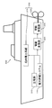
- FIG. 2 is a diagram schematically showing a ship 300 on which the power storage system 100 is mounted.
- the use of the power storage system 100 shown in FIG. 1 is not particularly limited, and is used for a moving body such as a vehicle.
- This power storage system 100 is used, for example, as an auxiliary power source for an electric propulsion ship (ship) 300 shown in FIG.
- the ship 300 uses electric propulsion (drive power of the motor generator 330) as the main drive source of the propeller 220.
- the main driving source (not shown) may be used as the main driving source of the propeller 220
- the electric propulsion driving force of the motor generator 330
- the motor generator 330 is connected to the power storage system 100, the main power supply 310, and the inboard power system 210 via the electric converter 320.
- the power storage system 100 is connected as an auxiliary power source together with the main power source 310 to the load 200 of the ship 300 (for example, the motor generator 330 for driving the inboard power system 210 and the propeller 220). Thereby, the power storage system 100 appropriately assists the main power supply 310 to supply power to the load 200 or receives power from the load 200 and stores it.
- the use of the power storage system 100 is not limited to the auxiliary power source of the ship 300, and may be used as, for example, a power storage system that supplies power to a car or a home.
- the power storage system 100 includes a secondary battery 10, a capacitor 11, and a controller 12.
- the power storage system 100 supplies power to the load 200 via the DC / AC inverter 13, or receives power from the load 200 and stores it in one or both of the secondary battery 10 and the capacitor 11.
- the load side terminal of the DC / AC inverter (power converter) 13 is connected to the load 200.
- the DC / AC inverter 13 converts the DC power input to the power supply side terminal into AC power, and outputs the AC power from the load side terminal.
- the DC / AC inverter 13 converts AC power input to the load side terminal into DC power, and outputs the DC power from the power source side terminal.
- the secondary battery 10 and the capacitor 11 are connected in parallel to the power supply side terminal of the DC / AC inverter 13.
- the capacitor 11 is connected to the power supply side terminal of the DC / AC inverter 13 via the DC / DC converter 17.
- the secondary battery 10 is connected to the power supply side terminal of the DC / AC inverter 13 via the DC link 20 constituted by a pair of wires, and the capacitor 11 is connected to the DC / DC converter 17 to the DC link 20. Connected through.
- a DC link capacitor 14 is connected between a pair of wires constituting the DC link 20.
- the DC link capacitor 14 smoothes fluctuations in the voltage of the DC link 20.
- a voltage sensor 15 is connected in parallel to the DC link capacitor 14. The voltage sensor 15 detects a DC link voltage Vdc (a voltage across the DC link capacitor 14), which is a voltage of the DC link 20.
- the secondary battery 10 is a large-capacity electricity storage device that accumulates electric charges through chemical reactions or physical reactions and releases the accumulated electric charges through reverse reactions.
- a first current sensor 16 is connected in series with the secondary battery 10. The first current sensor 16 is provided between the connection point between the secondary battery 10 and the capacitor 11, and detects a current Ib that is discharged from the secondary battery 10 or charges the secondary battery 10.
- Capacitor 11 is a high-power storage device that directly accumulates charges (without going through a reaction) and directly discharges the accumulated charges.
- the capacitor 11 for example, a lithium ion capacitor or an electric double layer capacitor is used.
- the capacitor 11 is connected to the DC link 20 via the DC / DC converter 17, and this connection point is provided between the first current sensor 16 and the DC link capacitor 14.
- the DC / DC converter 17 changes the current of the capacitor 11 by changing the conduction rate.
- the DC / DC converter 17 may have a step-up function or a step-down function that can change the voltage.
- a DC reactor 18 (DCL) is connected in series with the DC / DC converter 17 between the DC / DC converter 17 and the connection point of the capacitor 11. The DC reactor 18 smoothes the current output from the DC / DC converter 17 or input to the DC / DC converter 17.
- a second current sensor 19 is connected in series with the DC / DC converter 17 between the DC / DC converter 17 and the DC link 20, and the second current sensor 19 is discharged from the capacitor 11 or charges the capacitor 11. The current Ic is detected.
- the controller 12 controls the DC / DC converter 17 so as to charge and discharge the capacitor 11 with priority over the secondary battery 10. That is, the controller 12 includes a first control unit 12a and a second control unit 12b.
- the first controller 12 a determines the current command value Ic * ( Capacitor current target value) is generated.
- the second control unit 12 b generates a conduction ratio D of the DC / DC converter 17 based on the deviation of the current Ic of the capacitor 11 from the current command value Ic *, and outputs this to the DC / DC converter 17.
- the controller 12 directly controls the current of the capacitor 11 and indirectly controls the current of the secondary battery 10. For this reason, the current flow in the entire power storage system 100 is controlled.
- the predetermined current command value Ib * is set to 0 (zero) or a value close to 0 (zero). Thereby, the current Ib of the secondary battery 10 is suppressed to a predetermined current command value Ib * during a load change. Therefore, according to the predetermined current command value Ib * , the number of times of charging / discharging of the secondary battery 10 is suppressed, and the capacitor 11 is charged / discharged with priority over the secondary battery 10 accordingly.
- the first control unit 12a includes a current Ibsoc * for maintaining the remaining capacity SOC (State Of Charge) (%) of the secondary battery 10 at a predetermined value, and the current Ib of the secondary battery 10 with respect to the current command value Ib * . Based on the deviation, a current command value Ic * for the capacitor 11 is generated. Thereby, the flow of current in the entire power storage system 100 is controlled while suppressing fluctuations in the remaining capacity SOC of the secondary battery 10.
- SOC State Of Charge
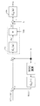
- FIG. 3 is a block diagram illustrating a configuration example of the controller 12 of the power storage system 100.
- the secondary battery 10 was used in a plateau region where the internal electromotive force Eb (V) was flat.
- the secondary battery 10 is used in the vicinity of SOC 50%.
- the DC link voltage Vdc (V) applied to the DC link capacitor 14 is the internal electromotive force of the secondary battery 10.
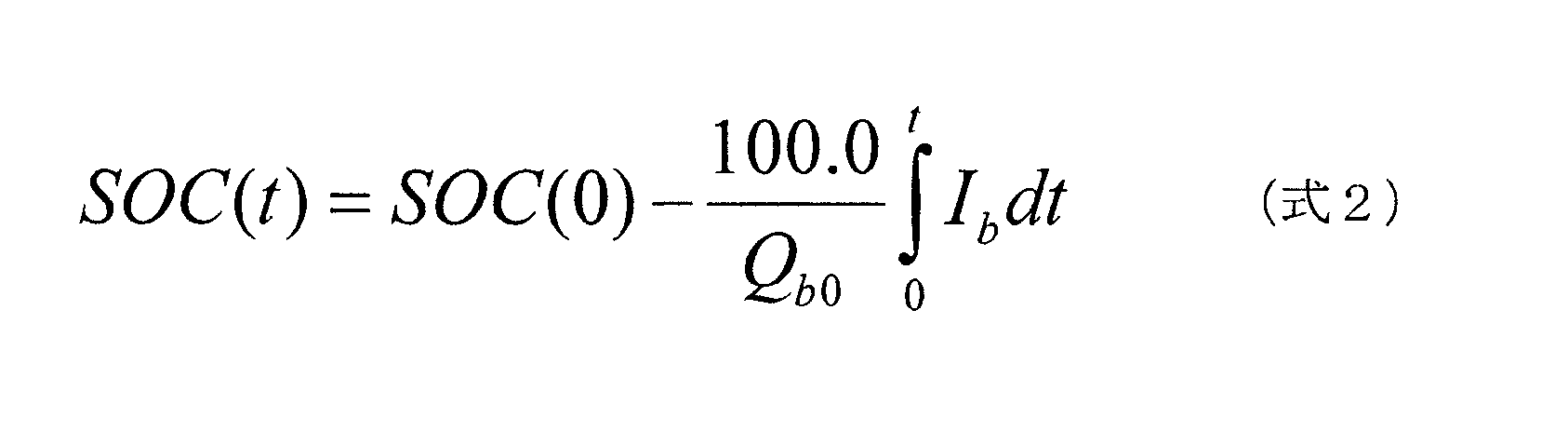
- Eb (V) This internal electromotive force Eb depends on the remaining capacity SOC (State Of Charge) (%) of the secondary battery 10 and is obtained by its function f (SOC (t)) as shown in the following (Formula 1).
- the remaining capacity SOC in (Formula 1) is expressed by the following (Formula 2).
- Ib is the current (A) of the secondary battery 10
- Qb0 is the rated capacity (Ah) of the capacitor 11.
- Idc Pac / Vdc (Formula 3) Due to the flow of the current Idc, a current Icdc (A) flows from the DC link capacitor 14. This current Icdc is expressed by the following (formula 4). In (Expression 4), Ic is the current (primary side current) (A) of the capacitor 11 on the primary side (DC link capacitor 14 side) of the DC / DC converter 17.
- Icdc Idc-Ib-Ic (Formula 4)
- Vdc the voltage (DC link voltage) of the DC link capacitor 14 drops.
- the DC link voltage Vdc is expressed by the following (formula 5).
- Cdc is the capacitance (F) of the DC link capacitor 14.
- Vdc ( ⁇ 1 / Cdc) ⁇ Icdc ⁇ dt (Formula 5) Due to the drop in the DC link voltage Vdc, a potential difference between the DC link voltage Vdc and the internal electromotive force Eb occurs, and the discharge current Ib (A) flows from the secondary battery 10 to the DC link capacitor 14. The discharge current Ib at this time is expressed by the following (formula 6). In (Expression 6), Rb is the internal resistance ( ⁇ ) of the secondary battery 10.
- the first current sensor 16 detects the current Ib and outputs it to the controller 12. As shown in FIG. 3, the controller 12 obtains the current Ib from the first current sensor 16 and controls the capacitor 11 to charge and discharge the secondary battery 10 in preference to supply the active power Pac. .
- the active power Pac (t) (W) is supplied from the secondary battery 10 and the capacitor 11 to the load 200 via the DC / AC inverter 13.
- the effective power Pac (t) is expressed by the power Pb (t) (W) of the secondary battery 10 and the power Pc (t) (W) of the capacitor 11 as represented by the following (formula 7).
- the total value is greater than 0 (W).
- the first control unit 12a determines the output power command value Pc * (W) of the capacitor 11 from the deviation (Ib * -Ib) of the current Ib from the first current sensor 16 with respect to the current command value Ib * of the secondary battery 10. Is calculated based on the following (formula 9). In (Equation 9), C1 (s) is a transfer function.
- the first control unit 12a obtains the DC link voltage Vdc from the voltage sensor 15. Then, the first control unit 12a obtains the current command value Ic * (capacitor current target value) of the capacitor 11 from the DC link voltage Vdc and the output power command value Pc * obtained by (Expression 9) below (Expression 10). )
- the primary current command value Ic * is the current command value (A) of the capacitor 11 on the primary side (DC link capacitor 14 side) of the DC / DC converter 17.
- the second control unit 12 b obtains the current Ic of the capacitor 11 from the second current sensor 19. Then, the second control unit 12b obtains the conduction ratio D of the DC / DC converter 17 from the deviation (Ic * ⁇ Ic) of the current Ic with respect to the primary current command value Ic * based on the following (formula 11). . In (Expression 11), C2 (s) is a transfer function.
- the power Pc of the capacitor 11 is supplied to the load 200 as the active power Pac. . If the power Pc of the capacitor 11 is equal to the active power Pac, the power Pc of the capacitor 11 is sufficient with respect to the active power Pac, so that the power is supplied to the load 200 using only the capacitor 11.
- the power Pc of the capacitor 11 is smaller than the effective power Pac due to a decrease in the remaining capacity SOC of the capacitor 11 or a limitation on the output current, the power Pc of the capacitor 11 is insufficient with respect to the effective power Pac. For this reason, the DC link voltage Vdc decreases, and a potential difference between the DC link voltage Vdc and the internal electromotive force Eb occurs. As a result, the discharge current Ib (A) flows from the secondary battery 10 to the DC link capacitor 14, and the power Pb of the secondary battery 10 of the following (formula 13) is supplied to the DC link capacitor 14. The power obtained by adding the power Pb of the secondary battery 10 to the power Pc of the capacitor 11 is supplied to the load 200 as the active power Pac.
- the controller 12 acquires the current Ib of the secondary battery 10 from the first current sensor 16, and obtains the remaining capacity SOC (t) of the secondary battery 10 from the above (Formula 2).
- the controller 12 calculates a current command value Ibsoc * for maintaining the SOC from the remaining capacity SOC (t) of the secondary battery 10 according to the following (formula 14).
- C3 is a correction term for SOC (t).
- Controller 12 controls remaining capacity SOC of secondary battery 10 by correcting current command value Ib * of secondary battery 10 with current command value Ibsoc * .
- Ibsoc * C3 ⁇ (SOC (t)) (Formula 14)
- the current command value Ibsoc * is added to the current command value Ib * .
- the current command value Ibsoc * may be added to the deviation of the current Ib from the current command value Ib * .
- the current of the secondary battery 10 is indirectly controlled by controlling the current of the capacitor 11 according to the conduction rate of the DC / DC converter 17, and the current flow in the entire power storage system 100 is controlled. Can be controlled. Therefore, the control parameter does not depend on the characteristics of load fluctuation, and the power storage system 100 is excellent in versatility.
- the capacitor 11 is charged and discharged with priority over the secondary battery 10. Therefore, since the frequency
- the current command value Ib * of the secondary battery 10 is set to 0 or a value close to 0. Thereby, the capacitor 11 can be easily charged / discharged preferentially over the secondary battery 10.
- the current command value Ib * of the secondary battery 10 may be set to a value close to 0 (zero), for example, a current value equal to or lower than the hourly current rate of the secondary battery 10.
- This one-hour current rate is the current value that can charge the remaining capacity SOC (State Of Charge) of the secondary battery from 0% to 100% in one hour, or the secondary battery SOC in 100 hours. Current value that can be discharged from 0 to 0%.
- the charging / discharging current Ib of the secondary battery 10 is limited to a current rate (1C) or less for one hour. As a result, it is possible to suppress the deterioration of the secondary battery 10 due to a larger current flowing through the secondary battery 10 from the capacitor 11, thereby extending the life of the secondary battery 10.
- the current Ib of the secondary battery 10 can be increased or decreased in proportion to the output of the entire power storage system 100.
- the load sharing ratio between the secondary battery 10 and the capacitor 11 is k: (1 ⁇ k)
- the load sharing ratio of the secondary battery 10 can be adjusted by the proportional coefficient k.
- the current command value Ic * of the capacitor 11 is reduced, The charging / discharging current Ib of the secondary battery 10 can be increased.
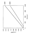
- the lifetime of the secondary battery 10 depends on the amount of heat generated by the secondary battery 10. As the calorific value of the secondary battery 10 increases, the secondary battery 10 deteriorates and the life of the secondary battery 10 is shortened. Therefore, the lifetime of the secondary battery 10 was evaluated based on the calorific value of the secondary battery 10 when the power storage system 100 was controlled according to the charge / discharge pattern.
- the current of the capacitor 11 was controlled by the conduction ratio D of the DC / DC converter 17 obtained in this way.
- the proportional compensator is used, the high frequency component is separated by HPF (High Pass Filter), and the power of the low frequency component is secondary.
- HPF High Pass Filter
- the time constant T EDLC of the HPF is larger than the period of the charge / discharge pattern, and the proportional gain kp of the proportional compensator is small in a range not reaching the upper limit voltage and the lower limit voltage of the capacitor 11. Set to value. For this reason, the time constant T EDLC and the proportional gain kp differ depending on the period and voltage of the charge / discharge pattern.
- the configuration of the power storage system 100 of the embodiment and the power supply system of the comparative example (each quantity of the secondary battery 10 and the capacitor 11, each internal resistance, capacitance, etc.), the control method of the DC / DC converter 17, and The parameters were the same.
- the secondary battery 10 capacity of the secondary battery 10 is set to 155.52 kWh so that the loss of the capacitor 11 can be sufficiently compensated.
- the initial power amount of the capacitor 11 was set to 2.15 kWh.
- the power storage system 100 of the example and the power supply system of the comparative example were controlled according to two types of charge / discharge patterns having different power magnitudes and charge / discharge frequencies. Then, since all or almost all of the loss amount (internal loss) of the secondary battery 10 becomes thermal energy, the loss amount Loss (kWh) was obtained as the heat generation amount according to the following (Formula 15).
- i is the current (A) of the secondary battery 10
- R is the internal resistance ( ⁇ ) of the secondary battery 10.
- the first charge / discharge pattern is lightly charged / discharged with respect to the capacitor 11. I can say that. Since the electric energy (2.083 kWh) of the second charge / discharge pattern is equivalent to the initial electric energy (2.15 kWh) of the capacitor 11, it can be said that the second charge / discharge pattern is heavy charge / discharge with respect to the capacitor 11.
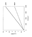
- the loss amount of the example at the time of 1200 (sec) in FIG. 6 was 72.2% of the loss amount of the comparative example.
- the loss amount of the example at 1200 (sec) in FIG. 7 was 51.3% of the loss amount of the comparative example.
- the loss amount of the example is smaller than that of the comparative example, the calorific value of the example is smaller than that of the comparative example. For this reason, it is thought that the thermal deterioration of the secondary battery 10 in an Example was suppressed and the lifetime of the secondary battery 10 was extended.
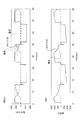
- the difference between the loss amount of the embodiment and the loss amount of the comparative example is derived from the power (kWh) of the secondary battery 10 and the current (A) of the secondary battery 10. That is, as shown in FIG. 8A, when the embodiment is charged / discharged with the second charge / discharge pattern, power is supplied only from the capacitor 11 at the start of discharging to the load 200, thereby reducing the remaining capacity of the capacitor 11. Accordingly, power is also supplied from the secondary battery 10. Next, power supply from the secondary battery 10 is terminated during the suspension, and power is supplied only to the capacitor 11 during charging. The same can be said for the electric current shown in FIG.
- the proportional compensator works so as to compensate the power command value of the capacitor 11 against the sudden increase / decrease in the remaining capacity SOC of the capacitor 11 due to the HPF function.
- the current of the secondary battery 10 always flows not only during discharging but also during charging.
- the loss amount (heat generation amount) in the embodiment is smaller than that in the comparative example.
- the remaining capacity SOC (%) of the secondary battery 10 of the example when charged and discharged for 1200 seconds with the second charge / discharge pattern shown in FIG. 10 was 38.9%.
- the remaining capacity SOC (%) of the secondary battery 10 of the comparative example when charged and discharged for 1200 seconds with the second charge / discharge pattern shown in FIG. 11 was 37.5%.
- the remaining capacity SOC of the secondary battery 10 of the example was equivalent to that of the comparative example.
- the remaining capacity SOC of each secondary battery 10 of the example and the comparative example at the start of charging / discharging was 50%.
- a DC / DC converter may be used as the power converter instead of the DC / AC inverter 13.
- the power storage system and the control method thereof according to the present invention are useful as a power storage system and a control method thereof that are highly versatile and have a long service life.
Abstract
Description
図1は、実施形態1に係る電力貯蔵システム100の構成を示す機能ブロック図である。図2は、電力貯蔵システム100を搭載した船舶300を概略的に示す図である。図1に示す電力貯蔵システム100の用途は、特に限定されず、たとえば、車両などの移動体に用いられる。この電力貯蔵システム100は、たとえば、図2に示す電気推進船舶(船舶)300の補助電源として用いられる。図2では、船舶300は、電気推進力(電動発電機330の駆動力)をプロペラ220の主駆動源として用いている。ただし、プロペラ220の主駆動源に主機(図示せず)と用いて、電気推進力(電動発電機330の駆動力)をプロペラ220の補助駆動源として用いてもよい。なお、電動発電機330は電動変換器320を介して電力貯蔵システム100、主電源310および船内電力系統210に接続している。 (Embodiment 1)
FIG. 1 is a functional block diagram illustrating a configuration of the
この電流Idcの流れによって、電流Icdc(A)がDCリンクキャパシタ14から流れる。この電流Icdcは下記(式4)により表される。(式4)で、Icは、DC/DCコンバータ17の1次側(DCリンクキャパシタ14側)のキャパシタ11の電流(1次側電流)(A)である。 Idc = Pac / Vdc (Formula 3)
Due to the flow of the current Idc, a current Icdc (A) flows from the
DCリンクキャパシタ14において電流Icdcが流れることにより、DCリンクキャパシタ14の電圧(DCリンク電圧)Vdcが降下する。DCリンク電圧Vdcは下記(式5)により表される。(式5)で、CdcはDCリンクキャパシタ14の静電容量(F)である。 Icdc = Idc-Ib-Ic (Formula 4)
When the current Icdc flows through the
DCリンク電圧Vdcの降下により、DCリンク電圧Vdcと内部起電力Ebとの電位差が生じ、二次電池10からDCリンクキャパシタ14へ放電電流Ib(A)が流れる。この時の放電電流Ibは下記(式6)により表される。(式6)で、Rbは二次電池10の内部抵抗(Ω)である。 Vdc = (− 1 / Cdc) ∫Icdc · dt (Formula 5)
Due to the drop in the DC link voltage Vdc, a potential difference between the DC link voltage Vdc and the internal electromotive force Eb occurs, and the discharge current Ib (A) flows from the
そして、放電電流Ibが流れると、電流Ibを第1電流センサ16が検知して制御器12へ出力する。図3に示すように、制御器12は、第1電流センサ16からの電流Ibを得て、キャパシタ11を二次電池10に優先して充放電させて有効電力Pacを供給するように制御する。 Ib = (Eb−Vdc) / Rb (Formula 6)
When the discharge current Ib flows, the first
そして、二次電池10の電流指令値Ib*(二次電池電流目標値)を0(零)(A)に設定すると、二次電池10の電力Pb(t)が0(W)に近づく。このため、下記(式8)の関係となり、キャパシタ11が二次電池10より優先的に使用されて、有効電力Pac(t)の全部をキャパシタ11が担うことになる。なお、キャパシタ11が二次電池10より優先的に使用されれば、二次電池10の電流指令値Ib*を0(A)でなく、0(零)に近い値(A)に設定してもよい。 Pac (t) = Pb (t) + Pc (t), t> 0 (Expression 7)
When the current command value Ib * (secondary battery current target value) of the
そこで、第1制御部12aは、二次電池10の電流指令値Ib*に対する第1電流センサ16からの電流Ibの偏差(Ib*-Ib)からキャパシタ11の出力電力指令値Pc*(W)を下記(式9)に基づいて求める。(式9)で、C1(s)は伝達関数である。 Pac (t) = Pc (t), t> 0 (Equation 8)
Therefore, the
第1制御部12aは、電圧センサ15からDCリンク電圧Vdcを得る。そして、第1制御部12aは、このDCリンク電圧Vdcと(式9)で求めた出力電力指令値Pc*とからキャパシタ11の電流指令値Ic*(キャパシタの電流目標値)を下記(式10)に従って演算して得る。1次側電流指令値Ic*は、DC/DCコンバータ17の1次側(DCリンクキャパシタ14側)のキャパシタ11の電流指令値(A)である。 Pc * = C1 (s) · (Ib * −Ib) (Formula 9)
The
次に、第2制御部12bは、第2電流センサ19からキャパシタ11の電流Icを得る。そして、第2制御部12bは、この電流Icの1次側電流指令値Ic*に対する偏差(Ic*-Ic)からDC/DCコンバータ17の通流率Dを下記(式11)に基づいて求める。(式11)で、C2(s)は伝達関数である。 Ic * = Pc * / Vdc (Formula 10)
Next, the
第2制御部12bは、通流率DをDC/DCコンバータ17に出力すると、1次側電流Icの電流がキャパシタ11から流れる。この電流は、DC/DCコンバータ17および直流リアクトル18を介してDCリンクキャパシタ14に流れる。このDCリンクキャパシタ14に供給される電力Pc(W)は下記(式12)で表される。 D = C2 (s) · (Ic * −Ic) (Formula 11)
When the
上記のとおり、二次電池10の電流指令値Ib*が0(零)または0(零)に近い値に設定されているため、キャパシタ11の電力Pcが有効電力Pacとして負荷200に供給される。このキャパシタ11の電力Pcが有効電力Pacに等しければ、有効電力Pacに対してキャパシタ11の電力Pcで足りているため、キャパシタ11のみで負荷200に電力を供給する。 Pc = Vdc · Ic (Formula 12)
As described above, since the current command value Ib * of the
また、二次電池10の内部起電力Ebは二次電池10の残存容量SOCに依存するため、上記のとおりにキャパシタ11の電流を制御するのに加えて、二次電池10の残存容量SOCも制御する必要がある。このため、制御器12は、第1電流センサ16から二次電池10の電流Ibを取得し、二次電池10の残存容量SOC(t)を上記(式2)から求める。制御器12は、二次電池10の残存容量SOC(t)からSOC維持用の電流指令値Ibsoc*を下記(式14)に従って算出する。(式14)においてC3はSOC(t)の補正項である。そして、制御器12は、電流指令値Ibsoc*によって二次電池10の電流指令値Ib*を補正することによって、二次電池10の残存容量SOCを制御する。 Pb = Vdc · Ib (Formula 13)
Further, since the internal electromotive force Eb of the
なお、図3では、電流指令値Ibsoc*が電流指令値Ib*に加算されているが、電流指令値Ibsoc*は、電流指令値Ib*に対する電流Ibの偏差に加算されてもよい。 Ibsoc * = C3 · (SOC (t)) (Formula 14)
In FIG. 3, the current command value Ibsoc * is added to the current command value Ib * . However, the current command value Ibsoc * may be added to the deviation of the current Ib from the current command value Ib * .
次に、上記構成の電力貯蔵システム100における二次電池10の長寿命化について実施例による検証結果を説明する。具体的には、二次電池10の寿命は二次電池10の発熱量に依存する。二次電池10の発熱量が大きいほど、二次電池10が劣化し、二次電池10の寿命が短くなる。よって、充放電パターンに応じて電力貯蔵システム100を制御した際の二次電池10の発熱量に基づいて二次電池10の寿命を評価した。 (Example)
Next, the verification result by an Example about the lifetime improvement of the
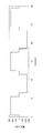
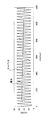
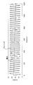
第1充放電パターンでは、図4に示すように、5秒間250kWの電力量(0.347kWh)を放電し、1秒間休止した後、5秒間250kWを充電し、1秒間休止するという周期12秒の充放電を繰り返す。第2充放電パターンでは、図5に示すように、15秒間500kWの電力量(2.083kWh)を放電し、2秒間休止した後、15秒間500kWを充電し、2秒間休止するという周期34秒の充放電を繰り返す。このように、第1充放電パターンの電力量(0.347kWh)がキャパシタ11の初期電力量(2.15kWh)より非常に小さいため、第1充放電パターンはキャパシタ11に対して軽充放電と言える。第2充放電パターンの電力量(2.083kWh)がキャパシタ11の初期電力量(2.15kWh)と同等であるため、第2充放電パターンはキャパシタ11に対して重充放電と言える。 Loss = (3600/1000) · ∫i 2 · Rdt (Formula 15)
In the first charge / discharge pattern, as shown in FIG. 4, a period of 12 seconds in which 250 kW of electric energy (0.347 kWh) is discharged for 5 seconds, paused for 1 second, charged for 250 seconds for 5 seconds, and paused for 1 second. Repeat charging and discharging. In the second charge / discharge pattern, as shown in FIG. 5, a period of 34 seconds in which 500 kW of electric power (2.083 kWh) is discharged for 15 seconds, paused for 2 seconds, charged 500 kW for 15 seconds, and paused for 2 seconds. Repeat charging and discharging. Thus, since the electric energy (0.347 kWh) of the first charge / discharge pattern is much smaller than the initial electric energy (2.15 kWh) of the
なお、上記実施の形態において、負荷200に直流電力を供給する場合には、電力変換器として、DC/ACインバータ13に代えて、DC/DCコンバータを用いてもよい。 (Other embodiments)
In the above embodiment, when DC power is supplied to the
11 キャパシタ
12 制御器
12a 第1制御部
12b 第2制御部
13 DC/ACインバータ
14 DCリンクキャパシタ
17 DC/DCコンバータ
20 DCリンク
100 電力貯蔵システム
200 負荷 DESCRIPTION OF
Claims (6)
- 負荷側端子が負荷に接続される電力変換器と、
前記電力変換器の電源側端子に接続された二次電池と、
前記電力変換器の電源側端子にDC/DCコンバータを介して前記二次電池に並列に接続されたキャパシタと、
前記二次電池より前記キャパシタを優先して充放電させるように前記DC/DCコンバータを制御する制御器と、を備えた、電力貯蔵システム。 A power converter with a load-side terminal connected to the load;
A secondary battery connected to the power supply side terminal of the power converter;
A capacitor connected in parallel to the secondary battery via a DC / DC converter to a power supply side terminal of the power converter;
And a controller for controlling the DC / DC converter so that the capacitor is charged and discharged with priority over the secondary battery. - 前記制御器は、
零または零に近い所定の二次電池電流目標値に対する前記二次電池の電流の偏差に基づいて前記キャパシタの電流目標値を生成する第1制御部と、
前記キャパシタの電流目標値に対する前記キャパシタの電流の偏差に基づいて前記DC/DCコンバータの通流率を生成し、これを前記DC/DCコンバータに出力する第2制御部と、を含む、請求項1に記載の電力貯蔵システム。 The controller is
A first control unit that generates a current target value of the capacitor based on a deviation of the current of the secondary battery with respect to a predetermined secondary battery current target value of zero or near zero;
And a second control unit that generates a conduction ratio of the DC / DC converter based on a deviation of the current of the capacitor with respect to a target current value of the capacitor, and outputs this to the DC / DC converter. The power storage system according to 1. - 前記所定の二次電池電流目標値は、前記二次電池の一時間電流率以下の電流値である、請求項2に記載の電力貯蔵システム。 The power storage system according to claim 2, wherein the predetermined secondary battery current target value is a current value equal to or less than an hourly current rate of the secondary battery.
- 前記所定の二次電池電流目標値は、零である、請求項2または3に記載の電力貯蔵システム。 The power storage system according to claim 2 or 3, wherein the predetermined secondary battery current target value is zero.
- 前記第1制御部は、前記二次電池のSOCを所定値に維持するための電流と、前記所定の二次電池電流目標値に対する前記二次電池の電流の偏差とに基づいて前記キャパシタの電流目標値を生成するように構成されている、請求項2乃至4のいずれかに記載の電力貯蔵システム。 The first control unit is configured to control a current of the capacitor based on a current for maintaining the SOC of the secondary battery at a predetermined value and a deviation of the current of the secondary battery with respect to the predetermined secondary battery current target value. The power storage system according to claim 2, wherein the power storage system is configured to generate a target value.
- 負荷側端子が負荷に接続される電力変換器と、前記電力変換器の電源側端子に接続された二次電池と、前記電力変換器の電源側端子にDC/DCコンバータを介して前記二次電池に並列に接続されたキャパシタと、制御器と、を備えた電力貯蔵システムの制御方法であって、
前記制御器は、前記二次電池より前記キャパシタを優先して充放電させるように前記DC/DCコンバータを制御する、電力貯蔵システムの制御方法。 A power converter having a load side terminal connected to a load; a secondary battery connected to a power source side terminal of the power converter; and a secondary battery connected to a power source side terminal of the power converter via a DC / DC converter. A method for controlling an electric power storage system comprising a capacitor connected in parallel to a battery and a controller,
The control method of the power storage system, wherein the controller controls the DC / DC converter so as to charge and discharge the capacitor with priority over the secondary battery.
Priority Applications (4)
| Application Number | Priority Date | Filing Date | Title |
|---|---|---|---|
| CA2916461A CA2916461C (en) | 2014-06-11 | 2015-06-10 | Power storage system and method of controlling the same |
| EP15806373.5A EP3157132B1 (en) | 2014-06-11 | 2015-06-10 | Hybrid electrical energy storage system and method for controlling same |
| CN201580030874.4A CN106464000B (en) | 2014-06-11 | 2015-06-10 | Electric power storage system and its control method |
| US15/318,304 US10263448B2 (en) | 2014-06-11 | 2015-06-10 | Power storage system and method of controlling the same |
Applications Claiming Priority (2)
| Application Number | Priority Date | Filing Date | Title |
|---|---|---|---|
| JP2014120288A JP6496496B2 (en) | 2014-06-11 | 2014-06-11 | Power storage system and control method thereof |
| JP2014-120288 | 2014-06-11 |
Publications (1)
| Publication Number | Publication Date |
|---|---|
| WO2015190094A1 true WO2015190094A1 (en) | 2015-12-17 |
Family
ID=54833205
Family Applications (1)
| Application Number | Title | Priority Date | Filing Date |
|---|---|---|---|
| PCT/JP2015/002905 WO2015190094A1 (en) | 2014-06-11 | 2015-06-10 | Electrical energy storage system and method for controlling same |
Country Status (6)
| Country | Link |
|---|---|
| US (1) | US10263448B2 (en) |
| EP (1) | EP3157132B1 (en) |
| JP (1) | JP6496496B2 (en) |
| CN (1) | CN106464000B (en) |
| CA (1) | CA2916461C (en) |
| WO (1) | WO2015190094A1 (en) |
Families Citing this family (11)
| Publication number | Priority date | Publication date | Assignee | Title |
|---|---|---|---|---|
| JP6781550B2 (en) * | 2016-02-01 | 2020-11-04 | 川崎重工業株式会社 | Power storage system and its control method |
| JP2017139844A (en) | 2016-02-01 | 2017-08-10 | 川崎重工業株式会社 | Electric power storage unit |
| TWM538649U (en) * | 2016-02-04 | 2017-03-21 | Kai Si Rong Co Ltd | Power supply device with capacitor of high capacity of electric energy |
| CN105703435B (en) * | 2016-03-22 | 2019-06-11 | 深圳市德利和能源技术有限公司 | Energy-storage system |
| US11065979B1 (en) | 2017-04-05 | 2021-07-20 | H55 Sa | Aircraft monitoring system and method for electric or hybrid aircrafts |
| US11063323B2 (en) | 2019-01-23 | 2021-07-13 | H55 Sa | Battery module for electrically-driven aircraft |
| US11148819B2 (en) | 2019-01-23 | 2021-10-19 | H55 Sa | Battery module for electrically-driven aircraft |
| US10479223B2 (en) | 2018-01-25 | 2019-11-19 | H55 Sa | Construction and operation of electric or hybrid aircraft |
| WO2019145777A1 (en) * | 2018-01-25 | 2019-08-01 | H55 Sa | Electrical powering or drive system for a motor in an electrically driven aircraft |
| JP7177159B2 (en) * | 2018-08-31 | 2022-11-22 | 川崎重工業株式会社 | Battery electric propulsion ship power supply system |
| WO2020208527A1 (en) | 2019-04-08 | 2020-10-15 | H55 Sa | Power supply storage and fire management in electrically-driven aircraft |
Citations (4)
| Publication number | Priority date | Publication date | Assignee | Title |
|---|---|---|---|---|
| JP2008228422A (en) * | 2007-03-12 | 2008-09-25 | Shimizu Corp | Method for controlling dispersed power supplies |
| JP2011182540A (en) * | 2010-03-01 | 2011-09-15 | Mitsubishi Electric Corp | Vehicular power supply system |
| WO2012017602A1 (en) * | 2010-08-02 | 2012-02-09 | パナソニック株式会社 | Vehicle power source device |
| JP2014060890A (en) * | 2012-09-19 | 2014-04-03 | Kuzumi Denshi Kogyo Kk | Power supply device |
Family Cites Families (8)
| Publication number | Priority date | Publication date | Assignee | Title |
|---|---|---|---|---|
| JP3430709B2 (en) * | 1995-04-28 | 2003-07-28 | いすゞ自動車株式会社 | Electric vehicle power control device |
| JP2900309B2 (en) * | 1996-08-30 | 1999-06-02 | 日晴金属株式会社 | Electric vehicle regeneration system |
| JP2002095174A (en) * | 2000-09-13 | 2002-03-29 | Casio Comput Co Ltd | Power system and its charging method |
| US7791216B2 (en) * | 2004-11-01 | 2010-09-07 | Ford Global Technologies, Llc | Method and system for use with a vehicle electric storage system |
| JPWO2009013891A1 (en) * | 2007-07-25 | 2010-09-30 | パナソニック株式会社 | Vehicle power supply |
| JP2010288414A (en) * | 2009-06-15 | 2010-12-24 | Toyota Motor Corp | Power supply device for vehicle |
| JP5189607B2 (en) * | 2010-02-04 | 2013-04-24 | トヨタ自動車株式会社 | Vehicle power supply |
| US9627999B2 (en) | 2012-11-07 | 2017-04-18 | Volvo Truck Corporation | Power supply device |
-
2014
- 2014-06-11 JP JP2014120288A patent/JP6496496B2/en active Active
-
2015
- 2015-06-10 US US15/318,304 patent/US10263448B2/en active Active
- 2015-06-10 CA CA2916461A patent/CA2916461C/en active Active
- 2015-06-10 CN CN201580030874.4A patent/CN106464000B/en active Active
- 2015-06-10 WO PCT/JP2015/002905 patent/WO2015190094A1/en active Application Filing
- 2015-06-10 EP EP15806373.5A patent/EP3157132B1/en active Active
Patent Citations (4)
| Publication number | Priority date | Publication date | Assignee | Title |
|---|---|---|---|---|
| JP2008228422A (en) * | 2007-03-12 | 2008-09-25 | Shimizu Corp | Method for controlling dispersed power supplies |
| JP2011182540A (en) * | 2010-03-01 | 2011-09-15 | Mitsubishi Electric Corp | Vehicular power supply system |
| WO2012017602A1 (en) * | 2010-08-02 | 2012-02-09 | パナソニック株式会社 | Vehicle power source device |
| JP2014060890A (en) * | 2012-09-19 | 2014-04-03 | Kuzumi Denshi Kogyo Kk | Power supply device |
Non-Patent Citations (1)
| Title |
|---|
| See also references of EP3157132A4 * |
Also Published As
| Publication number | Publication date |
|---|---|
| CA2916461A1 (en) | 2015-12-17 |
| EP3157132A4 (en) | 2018-02-21 |
| US10263448B2 (en) | 2019-04-16 |
| CN106464000A (en) | 2017-02-22 |
| CA2916461C (en) | 2016-11-01 |
| JP2016001936A (en) | 2016-01-07 |
| JP6496496B2 (en) | 2019-04-03 |
| EP3157132B1 (en) | 2019-11-20 |
| US20170126025A1 (en) | 2017-05-04 |
| EP3157132A1 (en) | 2017-04-19 |
| CN106464000B (en) | 2019-04-16 |
Similar Documents
| Publication | Publication Date | Title |
|---|---|---|
| JP6496496B2 (en) | Power storage system and control method thereof | |
| JP6236391B2 (en) | Device for balancing the amount of charge for power batteries | |
| WO2015129117A1 (en) | Soc estimation device for secondary battery | |
| JP5546649B2 (en) | Vehicle power supply system | |
| US9956888B2 (en) | Power supply system | |
| US10576835B2 (en) | Energy storage device, transport apparatus, and control method | |
| JP2006352970A (en) | Controller of power supply device | |
| JP5000025B1 (en) | Charge / discharge device | |
| JP6313522B2 (en) | Power control apparatus and power control system | |
| JP5386457B2 (en) | Power regeneration device | |
| JP2011130534A (en) | Power supply device for vehicle | |
| KR101567222B1 (en) | On-board charger and method for controlling thereof | |
| JP2017070077A (en) | Power storage device, transportation equipment, and control method | |
| CN107592953B (en) | Charge/discharge control device, mobile body, and power share determination method | |
| JP6358376B2 (en) | Storage battery conversion device, power supply system, and power supply control method | |
| JP5543018B2 (en) | Vehicle power supply system | |
| JP7337482B2 (en) | power supply | |
| JP6698169B2 (en) | Storage battery system | |
| JP6485871B2 (en) | Fuel cell system | |
| JP6611118B2 (en) | Power converter and industrial machine using the same | |
| JP2016063724A (en) | vehicle | |
| WO2021053730A1 (en) | Electric power supply system, method of controlling the same, and device | |
| JP2022173746A (en) | Power source device | |
| JP2014200149A (en) | Power system | |
| JP2020061811A (en) | Control arrangement of electrical power system |
Legal Events
| Date | Code | Title | Description |
|---|---|---|---|
| ENP | Entry into the national phase |
Ref document number: 2916461 Country of ref document: CA |
|
| 121 | Ep: the epo has been informed by wipo that ep was designated in this application |
Ref document number: 15806373 Country of ref document: EP Kind code of ref document: A1 |
|
| NENP | Non-entry into the national phase |
Ref country code: DE |
|
| WWE | Wipo information: entry into national phase |
Ref document number: 15318304 Country of ref document: US |
|
| REEP | Request for entry into the european phase |
Ref document number: 2015806373 Country of ref document: EP |
|
| WWE | Wipo information: entry into national phase |
Ref document number: 2015806373 Country of ref document: EP |