WO2015186199A1 - Système de diffusion numérique et procédé de diffusion numérique - Google Patents
Système de diffusion numérique et procédé de diffusion numérique Download PDFInfo
- Publication number
- WO2015186199A1 WO2015186199A1 PCT/JP2014/064773 JP2014064773W WO2015186199A1 WO 2015186199 A1 WO2015186199 A1 WO 2015186199A1 JP 2014064773 W JP2014064773 W JP 2014064773W WO 2015186199 A1 WO2015186199 A1 WO 2015186199A1
- Authority
- WO
- WIPO (PCT)
- Prior art keywords
- broadcast
- signal
- station
- terrestrial
- digital
- Prior art date
Links
Images


Classifications
-
- H—ELECTRICITY
- H04—ELECTRIC COMMUNICATION TECHNIQUE
- H04N—PICTORIAL COMMUNICATION, e.g. TELEVISION
- H04N21/00—Selective content distribution, e.g. interactive television or video on demand [VOD]
- H04N21/20—Servers specifically adapted for the distribution of content, e.g. VOD servers; Operations thereof
- H04N21/23—Processing of content or additional data; Elementary server operations; Server middleware
- H04N21/236—Assembling of a multiplex stream, e.g. transport stream, by combining a video stream with other content or additional data, e.g. inserting a URL [Uniform Resource Locator] into a video stream, multiplexing software data into a video stream; Remultiplexing of multiplex streams; Insertion of stuffing bits into the multiplex stream, e.g. to obtain a constant bit-rate; Assembling of a packetised elementary stream
- H04N21/2362—Generation or processing of Service Information [SI]
Definitions
- the present invention relates to a digital broadcasting system for performing terrestrial digital broadcasting, a digital broadcasting method, and a digital broadcasting method for broadcasting an emergency alert in a specific area.
- NIT Network Information Table
- the network information table in the program specification information describes information such as the frequency and modulation method related to the broadcast transmission line, and the receiver facilitates the operation such as selection of the broadcast channel. It is used to do. Since the network ID (network_id) described in the NIT corresponds one-to-one to each broadcast area and each channel (such a state may be referred to as "unique"), digital broadcast reception is possible. In the machine, channel selection can be easily performed by the network ID.
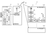
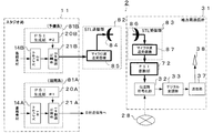
- FIG. 12 shows an example of the configuration of a conventional terrestrial digital broadcast system.
- the program production and editing facility 211 which is a studio system of a terrestrial digital broadcaster
- the broadcast program produced at the station and supplied from the camera 212, VTR or other recording device 213, or satellite communication transceiver 263 is selected by the switcher 214, encoded by the full segment encoder 215 and converted to a full segment TV signal,
- the program multiplexer 222 of the multiplexer 221 multiplexes the signal with other broadcast signals.
- the multiplexed signal is the frame synchronization signal generated by the frame synchronization signal generation unit 223, the transmission control information generated by the transmission control information generation unit 224, and the invalid packet signal generation unit 225.
- a broadcast signal in the form of a transport stream for broadcasting which is a signal format generated and multiplexed with an invalid packet signal inserted to adjust the transmission rate to a predetermined rate (herein, It is transmitted to the transmitting station 231 via the broadcast TS signal distribution circuit 228 as “broadcast TS signal”.
- the broadcast TS signal transmitted to the local station transmission station 231 is supplied to the transmission path coding unit 232 and converted into a predetermined error correction code and modulation scheme, and then the inverse Fourier transform unit 234 in the digital modulation unit 233 It is converted into an Orthogonal Frequency Division Multiplex (OFDM) signal which is a signal format of terrestrial digital broadcasting.
- OFDM Orthogonal Frequency Division Multiplex
- the frequency is converted into a transmission frequency in the frequency conversion unit (U / C) 236.
- U / C frequency conversion unit
- digital broadcasting services such as one-segment broadcasting that enables reception on mobile terminals etc. and data broadcasting that provides additional information such as broadcast content and independent information such as news and weather forecast are provided.
- Data broadcasting is an effective means of accurately delivering information to viewers in the event of a disaster.
- These broadcast services include video down converter 216, one-segment encoder 217, data broadcast production terminals (for full segment) 218A, same (for one segment) 218B, and data broadcast transmission devices 219A and 219B, which are facilities other than the main TV broadcast service.
- the program will be produced and multiplexed.
- program specification information is multiplexed in order to facilitate broadcast station selection, program selection, and the like in a receiver.
- the receiver can obtain a predetermined broadcast channel from among a plurality of broadcast radio waves in the area. Can be easily selected.
- the same national broadcast program may be broadcast in the same time zone, but in the NIT multiplexed in the broadcast signal for each broadcast station Since each local station is assigned a unique ID number, the receiver can identify interference with the broadcast area by identifying whether it is a broadcast station in its own area or not by knowing this ID number. Can be prevented.
- Such program specification information is generated by the program arrangement information generation unit 220 installed for each broadcast station and multiplexed into a broadcast TS signal.
- the above shows the facilities of the broadcaster in the case of covering the broadcast area of a specific area, but in the case of severe disaster, it is difficult to continue the broadcasting operation simply by multiplexing the facilities There is a need for a broadcast backup that is inexpensive and easy to operate.
- broadcast program is produced by the program production and editing facility 211 and distributed to the transmitting stations throughout the country via the network distributing broadcast TS signals for the whole country, from there digital broadcasting
- broadcast TS signals may be distributed to local station transmission stations throughout the country through satellite communication lines.
- this method can broadcast only a uniform broadcast program across the country, so local broadcast services, especially local news in a specific area, local government information, and disasters such as earthquakes and typhoons that are expected to cause serious damage in specific areas.
- the provision of information is limited.
- the broadcast TS signal is a broadcast signal common to all areas, and is sent to the local station transmission station 231 of each area via the satellite communication line. Since this method requires the viewer to perform complicated operations such as having to select broadcast information related to each area from a large amount of data broadcast information for the area, the data broadcast information specialized for the area Is difficult to be used. In addition, there is a risk of missing information that requires emergency such as a typhoon or an earthquake.
- Japanese digital terrestrial television broadcasting includes a function of automatically activating a receiver by an emergency alert.
- an activation control signal (emergency alert broadcast activation flag) is included in a TMCC (Transmission and Multiplexing Configuration Control) signal that controls the receiver, and turning on this signal enables emergency activation
- the receiver can be turned on automatically from the power off state.
- This function is a very effective means for transmitting an emergency alert such as nighttime when most of the receivers are off.
- the activation control signal in the TMCC signal and the dummy byte portion in the broadcast TS signal are multiplexed and transmitted from the studio to transmission stations throughout the country via the broadcast network.
- the present invention solves the problems of the prior art as described above, and enables inexpensive and easy-to-use digital broadcast systems and digital broadcast methods that allow viewers in respective regions to view information for each region reliably. Intended to be provided. Furthermore, the present invention provides a digital broadcasting method that effectively utilizes the function of automatically activating the receiver according to the ISDB-T emergency alert.
- one aspect of the present invention is a communication that distributes a broadcast TS signal with a studio station (11) that generates a transport stream format broadcast signal (hereinafter referred to as "broadcast TS signal").
- broadcast TS signal For terrestrial digital broadcasting, which receives the broadcast TS signal distributed via the line (58), converts it into a terrestrial digital broadcast signal, and transmits it to a terrestrial broadcast receiver of the broadcast area at a predetermined radio frequency
- a digital broadcast system comprising a transmission station (31), wherein the terrestrial digital broadcast transmission station rewrites program specification information included in the broadcast TS signal into program specification information specified for the broadcast area 72), and the broadcast TS signal can be broadcasted to different terrestrial broadcast areas.
- the program arrangement information in the broadcasting TS signal is transmitted to each terrestrial wave in one or a plurality of terrestrial broadcasting transmitting stations which take charge of the respective broadcasting areas for one or a plurality of broadcasting areas.
- the program specific information specified in the broadcast area and broadcast it is possible to receive the broadcast service as usual without changing the setting of the receiver in the broadcast area in any broadcast area in an emergency. it can.
- the studio station has a data broadcast production and transmission unit (22) that generates different regional data broadcast content and adds an identifier associated with the generated data broadcast content to program specific information of the region where the data broadcast content is broadcast. Is preferred. Furthermore, it is preferable that the terrestrial broadcast receiver select an identifier corresponding to the broadcast area from the program specific information rewritten by the PSI rewriter (72) and display the content for the area. As a result, the broadcast area of the transmitting station is rewritten by rewriting the program specifying information in the broadcasting TS signal at the transmitting station for terrestrial digital broadcasting in each area into the NIT and related program specifying information assigned to the transmitting station. The receiver inside can automatically select and display the data broadcasting information for the area, disaster information and the like.
- the studio station has an input unit for inputting an area code of one or more areas for performing emergency broadcast in the program specific information, and the transmitting station for terrestrial digital broadcasting transmits the input area code. It has a collating unit that collates with the area code assigned to the location, and an activation unit that activates an emergency broadcast activation control flag in the digital broadcast signal when there is a matching area code.
- the broadcast is performed in the PSI rewriting unit (72) of the transmission station of the corresponding area.
- the emergency broadcast activation control flag in the transmission control information in the TS signal only the receiver in the area requiring emergency activation is activated, so that disaster information is preferentially displayed on the television screen to be viewed by the viewer. It is possible to send out the Early Warning Broadcasting System, which calls for the warning of
- the studio station includes a broadcast TS signal compression device (73) that deletes packets not transmitting information from the broadcast TS signal and compresses the transmission rate, and the terrestrial broadcast transmission station compresses the transmission TS signal by the broadcast TS signal compression device. It is preferable to provide a broadcast TS signal decompressing device (74) which reinserts the packet into the compressed broadcast TS signal and decompresses the packet into a broadcast TS signal before compression. As a result, unnecessary packets (areas) on the receiving side such as invalid packets are deleted from the broadcast TS signal distributed via the distribution line, so that the transmission rate of the broadcast TS signal can be reduced. The required bandwidth can be reduced.
- a receiving unit for receiving one broadcast TS signal generated at a studio station, and program identification information included in the broadcast TS signal received by the receiving unit on the ground of the transmitting station.
- a transmitting station for terrestrial broadcasting characterized by comprising: a PSI rewriting unit which rewrites program specific information specified in a wave broadcasting area.
- the steps of generating one broadcasting TS signal, distributing the generated broadcasting TS signal to one or more terrestrial broadcasting transmission stations, and distributing to the terrestrial broadcasting transmission stations Rewriting the program identification information included in the broadcast TS signal into the program identification information specified in the terrestrial broadcast area, converting the rewritten broadcast TS signal into a terrestrial digital broadcast signal to obtain one broadcast TS And B. broadcasting the signal to different terrestrial broadcast areas.
- an area code of one or more areas is recorded in the program specifying information, and the program specifying information recorded with the area code is a broadcast TS signal.
- the broadcast TS signal multiplexed in a transmitting station for terrestrial digital broadcasting that receives the broadcasting TS signal generated at the studio station and converts it into a terrestrial digital broadcasting signal and transmits the step to be multiplexed
- the transmission station for digital terrestrial broadcasting collates the area code of one or more areas with the area code assigned to the transmission area, and if there is a matching area code, And D. activating an emergency broadcast start control flag in the terrestrial digital broadcast signal.
- the program specific information included in the broadcast TS signal generated by the studio station is designated as the terrestrial broadcasting area at the transmitting station for terrestrial broadcasting damaged by a natural disaster or the like. Since the program can be rewritten to the specified program specific information, it becomes possible to receive the broadcast service of one or more affected areas by distributing the broadcast TS signal, and the information for each area is required by the inexpensive and easy operation. Delivered to district viewers.
- the broadcast TS signal in which the program specific information in which the area code is recorded is recorded is collated with the area code assigned to the transmission station at the transmission station for digital terrestrial broadcasting. If there is a matching area code, the emergency broadcast activation control flag is activated to automatically activate the receiver in the area, so that an area-limited emergency alert can be issued.
- FIG. 1 is a block diagram showing a configuration of a digital broadcast system according to a first embodiment. It is explanatory drawing which shows the structure of the broadcast TS signal produced
- FIG. 5 is a configuration diagram of program identification information according to the first embodiment. It is a block diagram which shows the structure of a PSI rewriting part. It is a figure which shows TS packet rewriting in a PSI rewriting part. It is a flowchart which starts the receiver for terrestrial digital broadcasting at the time of emergency alert broadcast.
- FIG. 7 is a block diagram showing the configuration of a digital broadcast system according to a third embodiment.
- FIG. 14 is a block diagram showing the configuration of a digital broadcast system according to a fourth embodiment.
- FIG. 14 is a block diagram showing the configuration of a digital broadcast system according to a fourth embodiment. It is a block diagram which shows the structure of broadcast TS signal expansion and PSI rewriting apparatus. It is a block diagram which shows the structure of the conventional terrestrial digital broadcasting system.
- FIG. 1 shows the configuration of a digital broadcast system according to the first embodiment.
- the digital broadcasting system 1 includes a studio station 11 for producing and editing broadcast program signals for the whole country, a communication distribution station 61, a communication line 58, and a plurality of local station transmitting stations (herein, , "Transmission Station for Digital Terrestrial Digital Broadcasting" or simply “Transmission Station”) 31A, ..., 31N.
- the local station transmitting stations 31A,..., 31N have the same configuration and may be simply denoted by reference numeral 31.
- the studio station 11 has a program production and editing function, and includes a switcher 14, a data broadcast production and transmission unit 22, a PSI generation unit 20, and a multiplexing unit 21.
- the communication distribution station 61 is provided in parallel with the studio station 11, and includes a communication transmitting and receiving antenna 62 and a communication transmitting and receiving device 63.
- the communication line 58 is via a communication satellite in this embodiment.
- the switcher 14 selects various program materials produced and supplied.
- the data broadcast production and delivery unit 22 produces a data broadcast signal
- the PSI generation unit 20 produces program specification information
- the multiplexing unit 21 produces the data broadcast signal and PSI produced by the data broadcast production and delivery unit 22
- the program specific information generated by the unit 20 is multiplexed to generate a broadcast TS signal.
- the program identification information multiplexed in the broadcast TS signal in this way can use other numbers than the ID numbers assigned to the local station.
- the data broadcast production and transmission unit 22 produces broadcast program signals for the whole country as data broadcast contents related to areas A,..., N to be broadcast, and the network ID of each target area for the contents for specific areas.
- An identifier to be displayed on the receiver side is acquired by the function getProgramID () of BML (Broadcast Markup Language).
- the identification information and the BML function are defined by ARIB STANDARD, ARIB TECHNICAL REPORT, etc., which are standards of the Radio Industry Association.
- the various program materials produced are selected by the switcher 14 and encoded and converted into digital signals (TV signals), and are generated by the data broadcasting signal produced by the data broadcast production / delivery unit 22 or the PSI generation unit 20
- the broadcast TS signal is generated by multiplexing in the multiplexing unit 21 together with the specified program identification information.
- the broadcast TS signal for the local station is transmitted to the communication transmitter / receiver 63 of the communication distribution station 61, and transmitted from the communication transmitter / receiver 63 to the local station transmission station 31 via the communication transmission / reception antenna 62 and the communication line 58. Ru.
- the local station transmission station 31 includes a reception antenna 71, a communication receiver 56, a PSI rewriting unit 72, a transmission path coding unit 32, a digital modulation unit 33, a transmission unit 37, and a transmission antenna 38.
- the receiving antenna 71 receives the broadcast TS signal sent from the communication line 58
- the communication receiver 56 receives the broadcast TS signal received by the receiving antenna 71
- the PSI rewriter 72 receives the broadcast received by the communication receiver 56.
- the program identification information in the TS signal is rewritten to the ID assigned to the local station.
- the transmission path coding unit 32, the digital modulation unit 33, the transmission unit 37, and the transmission antenna 38 are transmission equipment for terrestrial broadcasting of the local station transmission station 31.
- the broadcast TS signal for the local station transmission station 31 transmitted from the communication distribution station 61 is received by the communication receiver 56 via the reception antenna 71.
- the program identification information in the received broadcast TS signal is rewritten by the PSI rewriter 72 to an ID assigned to the local station.
- the broadcast TS signal for the local station is converted / modulated through the transmission path coding unit 32, the digital modulation unit 33, and the transmission unit 37, which are transmission facilities for terrestrial broadcast of the local station transmission station 31. After that, it is wirelessly transmitted from the transmitting antenna 38 as a broadcast signal for the broadcast area of the local station.
- the receiver of the local station transmission station 31 (shown in FIG. First, it is possible to automatically select and display data broadcast information for the area, using the ID number assigned to the area as a return value of the getProgramID () number.
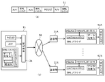
- FIG. 2 shows the configuration of the broadcast TS signal 51 generated in the studio station 11.
- the broadcast TS signal 51 includes a video / audio signal (A / V) common to each area, program specific information (PSI / SI: Program Specific Information / Service Information), and the like. It is composed of data broadcasting signals composed of different contents (abbreviated as BML) for regional use.
- BML data broadcasting signals composed of different contents
- FIG. 2 (b) the program identification information (PSI / SI), the video / audio signal (A / V), and the network_id of each area in the multiplexing unit 21 of the studio station 11 performing program editing and production.
- Each broadcast data (BML content) for each area which is displayed on the receiver side by the function getProgramID (), is multiplexed to form one broadcast TS signal 51.
- the broadcast TS signal 51 is sent to the transmitting station 31 of each area via the communication line 58.
- the broadcast TS signal 51 is digitally modulated after the network_id information in PSI / SI is rewritten in the PSI rewriter (see FIG. 1) provided in the local station transmitters 31A,. It will be broadcast in the area.
- the terrestrial digital broadcast receivers 41A, ..., 41N in the respective areas acquire and store PSI / SI information from the signals broadcasted from the transmitting stations 31A, ..., 31N in the respective areas.
- the received signal uses the network_id (identifier) in the PSI / SI information acquired as the return value of the getProgramID () function in the BML browser to select the data broadcast content for the area.
- the selected data broadcast content is combined with the A / V signal and displayed on the display of the receiver.
- the terrestrial digital broadcast receivers 41A,..., 41N in each area can display data broadcast contents for each area.
- a network ID, a TSID, and a service ID are assigned to each broadcaster in each area according to an operation rule defined for each country. These ID numbers are defined in the NIT and are recommended to be stored by the receiver.
- PAT Program Association Table
- PMT Program Map Table
- the structure of the TS signal is defined in ARIB TR-B14.
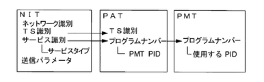
- FIG. 3 is a block diagram of program specification information indicating the relationship between NIT, PAT and PMT.
- the NIT contains information of network identification, TS identification, service identification (service type), and transmission parameters.
- the PAT includes NIT TS identification information, TS identification information extracted from service identification information, and program number information (that is, PMT PID).
- the PMT includes program number information (PID to be used) extracted from program number information of PAT.
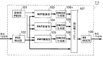
- FIG. 4 shows the detailed configuration of the PSI rewriting unit 72.
- the PSI rewriting unit 72 stores the program identification information such as the ID number (NIT) of the local station, the PID detection unit 102 that detects the type of packet of the broadcast TS signal, and the NIT rewriting that rewrites the NIT.
- NIT ID number
- PAT rewriting unit 104 for rewriting PAT
- PMT rewriting unit 105 for rewriting PMT
- CRC32 generation unit 106A for recalculating error detection parity (hereinafter abbreviated as CRC32) along with rewriting of the ID number 106B, 106C
- a packet selection unit 107 for selecting a packet to be transmitted
- an RSECC unit 108 for recalculating a Reed-Solomon error correction code (RSECC) of the broadcast TS.
- RSECC Reed-Solomon error correction code
- the broadcast TS signal transmitted from the studio station is supplied to the PID detection unit 102, and the PID detection unit 102 detects the type (packet ID) of the packet of the broadcast TS signal.
- the packet type information detected by the PID detection unit 102 is supplied to the NIT rewrite unit 103, the PAT rewrite unit 104, the PMT rewrite unit 105, and the packet selection unit 107, respectively.
- the ID numbers (network identification information, TSID, service identification information) of the local station stored in the PSI storage unit 101 are respectively supplied to the NIT rewriting unit 103, the PAT rewriting unit 104, and the PMT rewriting unit 105.
- each of the rewrite units 103, 104, and 105 is supplied to the packet selection unit 107 via the CRC 32 generation units 106A, 106B, and 106C.
- the output of the packet selection unit 107 is output as a broadcast TS signal of the broadcast area via the RSECC unit 108.
- FIG. 5 shows TS packet rewriting in the PSI rewriting unit 72.
- the rewritten NIT is stored in the PSI storage unit 101. Further, ID numbers (PAT, PMT) necessary for rewriting other program specific information are extracted from the NIT.
- PID packet ID
- NIT information on the packet sent in NIT rewrite section 103
- the CRC 32 is recalculated in accordance with the rewritten NIT in the CRC 32 generation unit 106 A, the rewritten packet is selected in the packet selection unit 107, and the Reed-Solomon error correction code of the rewritten TS packet is selected in the RSECC unit 108 ( Recalculates RSECC and adds parity again.
- the PAT rewriting unit 104 transmits the information of the sent packet (the TSID of the PAT and the program number) to the TSID of the PAT stored in the PSI storage unit 101 and the TSID. Rewrite to the program number. Then, as in the case of the NIT, the CRC 32 is recalculated in accordance with the rewritten PAT in the CRC 32 generation unit 106 B, the rewritten packet is selected in the packet selection unit 107, and the rewritten TS packet is selected in the RSECC unit 108.
- the Reed-Solomon error correction code of is recomputed and repared.
- the PMT rewriter 105 rewrites the information (program number of the PMT) of the sent packet to the program number of the PMT stored in the PSI storage unit 101. . Then, as in the case of the NIT, the CRC 32 is recalculated in accordance with the rewritten PMT in the CRC 32 generation unit 106 C, the rewritten packet is selected in the packet selection unit 107, and the rewritten TS packet is selected in the RSECC unit 108.
- the Reed-Solomon error correction code is recomputed and repared. Further, as necessary, rewriting of identification information is also performed on program identification information other than PAT and PMT. In this way, broadcast TS signals of other areas can be converted into broadcast TS signals of the local station. Then, packets not to be rewritten (video packets, audio packets) are output as they are.
- the program identification information multiplexed in the broadcast TS signal supplied from the communication receiver 56 is rewritten by the PSI rewriter 72 to the ID number assigned to the local station, so that the local station Receivers in the broadcast area can recognize that they have the same ID number as normal service and can receive them normally. Therefore, it is possible to prevent a situation in which the receiver can not recognize the network ID and can not receive in the broadcast area of the local station. In addition, it is possible to recognize this ID number and automatically recognize and display a data broadcast associated with the network ID number for the area.
- the broadcast station within the broadcast area of the local station can automatically select and display data broadcast information for the area, using the ID number assigned to the area as the return value of the getProgram ID () number.
- the configuration of the digital broadcast system according to the second embodiment is the same as that of the first embodiment, but in the present embodiment, the studio station 11 further includes an input unit (not shown) for inputting the area code, The local station transmitter 31 is activated to activate an emergency broadcast activation control flag in a digital broadcast signal, and a verification unit (not shown) that collates the area code with the area code assigned to the local station transmitter 31. Part (not shown).
- the terrestrial digital broadcast receiver 41 can not be started automatically.
- the control information is set to be activated, the activation control signal is activated in the area where the broadcast TS signal is distributed and the emergency information is displayed, which may cause unnecessary confusion.
- the input unit inputs an area code of one or more areas for performing an emergency broadcast to the program specification information.
- the collation unit collates the target area code in the emergency information descriptor in the PMT multiplexed in the broadcast TS signal supplied to the transmission station 31 with the area code assigned to the transmission station, and matches the area If the code is present, a signal is sent to the activation unit.
- the activation unit activates an emergency broadcast activation control flag in the digital broadcast signal based on the signal from the collation unit.
- the PSI generation unit 20 inserts the emergency information descriptor into the PMT when the emergency alert broadcast is activated, describes the area code of the target area to be automatically activated, and multiplexes the area code into the broadcast TS signal.
- the broadcast TS signal is distributed to the communication receiver 56 from the receiving antenna 71 installed in the local station transmission station 31 via the communication distribution station 61 and the communication line 58.
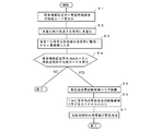
- FIG. 6 is a flowchart for activating the terrestrial digital broadcast receiver 41 at the time of emergency alert broadcast.
- step 1 the PSI generation unit 20 in the studio station 11 writes one or more area codes for performing emergency alert broadcasting in the emergency information descriptor in the PMT.
- this emergency information descriptor is multiplexed with the broadcast TS signal in the multiplexing unit 21 together with other control information.
- step 3 the multiplexed broadcast TS signal is distributed to the local station transmission station 31 of each area via the communication line 58 (see FIG. 1), and the received and demodulated broadcast TS signal is PSI rewriter 72. Is input to
- step 4 the collating unit included in the PSI rewriting unit 72 includes one or more area codes recorded in the emergency information descriptor in the PMT multiplexed in the broadcast TS signal and the transmission place The area code assigned to is matched. If there is a matching area code, in step 5 (S5), the emergency broadcast activation control flag in the control information multiplexed in the broadcast TS signal is activated and sent to the transmission line encoding unit 32 of the next stage. , If there is no matching area code, exit.
- step 6 the transmission path coding unit 32 changes the start control flag for emergency broadcast in the TMCC signal from off to on to broadcast toward the area concerned.
- step 7 the receiver 41 in the area monitors the emergency broadcast activation control flag in the TMCC signal, and when it is on, automatically activates the receiver.
- the digital broadcast signal is checked if one or more area codes described in the emergency information descriptor in the PMT are compared with the area code assigned to the self transmission station.
- the start control flag for emergency broadcast in the TMCC signal can be activated and broadcasted, and the receivers in the area can be automatically activated.
- FIG. 7 shows the configuration of a digital broadcast system according to the third embodiment.
- the digital broadcast system 2 shown in FIG. 7 has a microwave transmission / reception system (STL :) instead of a distribution network including the communication distribution station 61, the reception antenna 71 of the local station transmission station 31, and the communication
- STL studio-inter-station relay apparatus
- the STL receiving unit 83 includes a microwave transmitting and receiving antenna 84 and a microwave transmitting and receiving device 87.
- the STL receiving unit 83 includes a microwave transmitting and receiving antenna 86 and a microwave transmitting and receiving device 87.
- the broadcast TS signal produced by the studio equipment spare system 81 B is supplied to the STL transmitter 82 and converted into a microwave digital modulation signal by the microwave transceiver 85, and then from the microwave transmission / reception antenna 84. It is transmitted to the STL receiving unit 83 carried into the local station transmitting station 31.
- the signal received by the microwave transmitting / receiving antenna 86 of the STL receiving unit 83 of the local station transmitting station 31 is demodulated by the microwave transceiver 87 and supplied to the PSI rewriting unit 72.
- the same effect as that of the first embodiment can be obtained without using a satellite communication system whose demand is particularly high at the time of severe disaster.
- a communication system other than a satellite communication system such as an optical fiber communication system may be used.
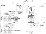
- FIG. 8 shows the configuration of a digital broadcast system according to the fourth embodiment.
- the broadcast TS signal compression device 73 is provided in the former stage of the communication distribution station 61 as an emergency backup in the studio station 11 and the broadcast TS signal decompression device 74 is transmitted and received in the local station transmission station 31. It arrange
- a compressed broadcast TS signal instead of transmitting a broadcast TS signal, a compressed broadcast TS signal, which is a broadcast TS signal with a bit rate compressed by deleting invalid packets, is transmitted.
- the bit rate value in countries with 6 MHz bandwidth is specified as 32.50 ... Mbps (43.34 ... Mbps in countries with 8 MHz bandwidth), and it is invalid to match this bit rate.
- a packet is inserted into the broadcast TS signal. Since the invalid packet signal does not transmit information, there is no problem in the broadcasting service even if it is not transmitted to the transmitting station.
- the transmission bit rate from which invalid packets have been eliminated is approximately 21 Mbps (for 6 MHz bandwidth) in the case of full segment plus (+) and one segment, so that significant bit rate reduction can be achieved.
- the broadcast TS signal produced by the studio facility 81 of the production and editing station for the whole country 11 has an invalid packet removed from the broadcast TS signal in the broadcast TS signal compression device 73 to generate a compressed broadcast TS signal.
- the compressed broadcast TS signal transmitted to the local station transmission station 31 is re-inserted into the compressed broadcast TS signal by the broadcast TS signal decompression device 74 and adjusted to a prescribed bit rate.
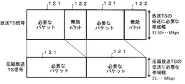
- FIG. 9 shows the configuration of a broadcast TS signal and a compressed broadcast TS signal.
- the broadcast TS signal composed of the necessary packet 121 and the invalid packet 122 unifies the interface between the multiplexing unit 21 in the studio station 11 and the channel coding unit 32 (see FIG. 7) in the local station transmission station 31.
- the transmission rate of the signal In order to set the transmission rate of the signal to an arbitrary transmission parameter setting of the broadcast wave (for example, in the case of 6 MHz broadcast band, 32.50 .... Mbps in 8 MHz broadcast band, 43.34 ... Mbps in 8 MHz broadcast band) It is set to. Therefore, the invalid packet 122 is added to the required packet 121 to match the transmission rate. Therefore, the invalid packet 122 does not have to be transmitted via the broadcast TS signal distribution line 28, and may be reproduced at a stage prior to the transmission line coding unit 32 at the local station transmission station 31.
- FIG. 9 shows a compressed broadcast TS signal which is a signal of the output end of the broadcast TS signal compression apparatus 73 (see FIG. 8), and is transmitted in a state where the invalid packet 122 is deleted. Since the insertion position of the invalid packet 122 is determined first by the transmission parameter of the broadcast wave, it can be reinserted without the insertion position information in the broadcast TS signal expander 74 provided in the transmission station 31. Therefore, the signal supplied from the broadcast TS signal decompression device 74 to the channel coding unit 32 is the broadcast TS signal 121. As described above, by using the broadcast TS signal compression device 73 and the broadcast TS signal decompression device 74, it is possible to compress the required bandwidth in the broadcast TS signal transmission line 28 without losing the predetermined effect.
- the bit rate of the compressed broadcast TS signal transmitted via the satellite channel 58 is 21 Mbps (in the case of 6 Mhz bandwidth), and the required satellite communication channel bandwidth can be significantly reduced. Along with this, it is also possible to reduce the required transmission power.
- the signal transmitted via the satellite line 58 is a compressed broadcast TS signal, but the signal at the output end of the studio equipment spare system 81 on the sending side and the input end of the PSI rewriting unit 72 on the receiving side. Since the format is a broadcast TS signal, the signal interface standard with the existing equipment is the same as that of the first embodiment.
- the required communication capacity can be significantly reduced, and the required communication line bandwidth can be further reduced.
- the required transmission power can be reduced, the reduced bandwidth and power can be allocated to another facility operation such as SNG ground station performing satellite news gathering by communication satellite.
- FIG. 10 shows the configuration of a digital broadcast system according to the fifth embodiment.
- the digital broadcast system 4 shown in FIG. 10 has a broadcast TS signal decompression device 74 which has transport stream signal processing functions such as frame synchronization processing, PID detection processing, clock reproduction processing, etc. for broadcast TS signals.
- the functions of the PSI rewriter 72 are integrated to share or integrate these common circuit functions, thereby reducing the number of circuits.
- the local station transmission station 31 is provided with a broadcast TS signal expander / PSI rewriter 75 in which both units are integrated. There is.
- the other configuration is the same as that of the digital broadcast system 3 (see FIG. 8).
- the compressed broadcast TS signal transmitted to the local station transmission station 31 is again inserted into the compressed broadcast TS signal in the broadcast TS signal decompression / PSI rewrite device 75 and adjusted to a prescribed bit rate, The ID number assigned to the local station is rewritten.
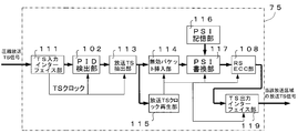
- FIG. 11 shows a detailed configuration of the broadcast TS signal decompression / PSI rewriting device 75.
- the broadcast TS signal expansion / PSI rewriter 75 is connected to the subsequent stage of the TS input interface unit 111 and the TS input interface unit 111 that reproduces the TS clock and extracts the TS packet, and detects the type of the broadcast TS signal packet.
- a broadcast TS extraction unit 113 connected to the subsequent stage of the PID detection unit 112 to extract data necessary for restoration of the broadcast TS
- an invalid packet insertion unit connected to the rear stage of the broadcast TS extraction unit 113 to insert an invalid packet 114
- the broadcast TS extraction unit 113 is connected to the rear stage of the broadcast TS signal and has a broadcast TS clock reproduction unit 115 that reproduces the broadcast TS clock from the data of the broadcast TS signal.
- the PSI storage unit 116 stores program identification information such as the ID number (NIT) of the local station, and the ID of the local station connected to the subsequent stage of the invalid packet insertion unit 114 and stored in the PSI storage unit 116 PSI rewriting unit 117 that rewrites program identification information such as a number, an RSECC unit 118 connected to the subsequent stage of the PSI rewriting unit 117 to recalculate a Reed-Solomon error correction code (RSECC), a TS connected to the subsequent stage of the RSECC generation unit 118 An output interface unit 119 is provided.
- NIT the ID number
- RSECC Reed-Solomon error correction code
- the TS clock extracted by the TS input interface unit 111 is supplied to each block of the PID detection unit 112 and the broadcast TS extraction unit 113. Also, the TS clock regenerated by the broadcast TS clock regeneration unit 115 is supplied to each block of the invalid packet insertion unit 114, the PSI rewrite unit 117, the RSECC generation unit 118, and the TS output interface unit 119.
- the broadcast TS signal decompression / PSI By integrating as the rewriting device 75, the device can be simplified and the cost can be reduced.
- the broadcast TS signal compression device 73 deletes the invalid packet, converts it into a transmission TS, and transmits it to the local station transmission station 31 via the satellite link 58.
- the TS signal is input to the TS input interface unit 111 of the broadcast TS signal expansion / PSI rewrite device 75, and the reproduction of the TS clock and the extraction of the TS packet are performed.
- the PID detection unit 112 monitors the PID to detect the type of packet.
- the broadcast TS extraction unit 113 extracts data necessary for restoring the broadcast TS.
- the broadcast TS clock recovery unit 115 generates a clock from the data of the extracted broadcast TS signal, and the invalid packet insertion unit 114 inserts an invalid packet according to the clock.
- the expanded broadcast TS signal is restored except for the Reed-Solomon error correction code parity.
- the program identification information of the broadcast TS signal is rewritten, the Reed-Solomon error correction code parity is recalculated in the RSECC unit 118, and the parity is added again to complete the broadcast TS signal of the broadcast area.
- the completed broadcast area broadcast TS signal is output and supplied to the transmission path encoding unit 32 (see FIG. 9) at the next stage.
- the same effect as that of the third embodiment can be obtained, and further reduction of the circuit function becomes possible. And the equipment cost and installation volume which are installed in a transmitting place can be reduced by the part which reduced the circuit.
Abstract
Priority Applications (2)
| Application Number | Priority Date | Filing Date | Title |
|---|---|---|---|
| BR112016028251A BR112016028251A2 (pt) | 2014-06-03 | 2014-06-03 | sistema de radiodifusão digital e método de radiodifusão digital |
| PCT/JP2014/064773 WO2015186199A1 (fr) | 2014-06-03 | 2014-06-03 | Système de diffusion numérique et procédé de diffusion numérique |
Applications Claiming Priority (1)
| Application Number | Priority Date | Filing Date | Title |
|---|---|---|---|
| PCT/JP2014/064773 WO2015186199A1 (fr) | 2014-06-03 | 2014-06-03 | Système de diffusion numérique et procédé de diffusion numérique |
Publications (1)
| Publication Number | Publication Date |
|---|---|
| WO2015186199A1 true WO2015186199A1 (fr) | 2015-12-10 |
Family
ID=54766298
Family Applications (1)
| Application Number | Title | Priority Date | Filing Date |
|---|---|---|---|
| PCT/JP2014/064773 WO2015186199A1 (fr) | 2014-06-03 | 2014-06-03 | Système de diffusion numérique et procédé de diffusion numérique |
Country Status (2)
| Country | Link |
|---|---|
| BR (1) | BR112016028251A2 (fr) |
| WO (1) | WO2015186199A1 (fr) |
Cited By (1)
| Publication number | Priority date | Publication date | Assignee | Title |
|---|---|---|---|---|
| WO2018003025A1 (fr) * | 2016-06-29 | 2018-01-04 | 株式会社タナビキ | Station de transmission à diffusion numérique terrestre et procédé de diffusion numérique |
Citations (4)
| Publication number | Priority date | Publication date | Assignee | Title |
|---|---|---|---|---|
| US20030081686A1 (en) * | 2001-11-01 | 2003-05-01 | Joon-Young Jung | PSIP converter and converting method and digital cable television broadcasting system using the PSIP converter |
| JP2004194265A (ja) * | 2002-10-17 | 2004-07-08 | Nippon Television Network Corp | 地上デジタル放送受信処理装置、地上デジタル放送中継伝送装置、放送情報記録装置及び地上デジタル放送中継伝送方法 |
| US20070183454A1 (en) * | 2006-02-08 | 2007-08-09 | Samsung Electronics Co.; Ltd. | System and method for digital multimedia broadcasting confinement service |
| JP2013243644A (ja) * | 2012-04-26 | 2013-12-05 | Nippon Hoso Kyokai <Nhk> | Stl/ttl回線用送信装置及びその受信装置 |
-
2014
- 2014-06-03 BR BR112016028251A patent/BR112016028251A2/pt not_active Application Discontinuation
- 2014-06-03 WO PCT/JP2014/064773 patent/WO2015186199A1/fr active Application Filing
Patent Citations (4)
| Publication number | Priority date | Publication date | Assignee | Title |
|---|---|---|---|---|
| US20030081686A1 (en) * | 2001-11-01 | 2003-05-01 | Joon-Young Jung | PSIP converter and converting method and digital cable television broadcasting system using the PSIP converter |
| JP2004194265A (ja) * | 2002-10-17 | 2004-07-08 | Nippon Television Network Corp | 地上デジタル放送受信処理装置、地上デジタル放送中継伝送装置、放送情報記録装置及び地上デジタル放送中継伝送方法 |
| US20070183454A1 (en) * | 2006-02-08 | 2007-08-09 | Samsung Electronics Co.; Ltd. | System and method for digital multimedia broadcasting confinement service |
| JP2013243644A (ja) * | 2012-04-26 | 2013-12-05 | Nippon Hoso Kyokai <Nhk> | Stl/ttl回線用送信装置及びその受信装置 |
Cited By (1)
| Publication number | Priority date | Publication date | Assignee | Title |
|---|---|---|---|---|
| WO2018003025A1 (fr) * | 2016-06-29 | 2018-01-04 | 株式会社タナビキ | Station de transmission à diffusion numérique terrestre et procédé de diffusion numérique |
Also Published As
| Publication number | Publication date |
|---|---|
| BR112016028251A2 (pt) | 2017-08-22 |
Similar Documents
| Publication | Publication Date | Title |
|---|---|---|
| KR100495545B1 (ko) | 수신시스템 및 디지털 방송시스템 | |
| US8548373B2 (en) | Methods and apparatus for identifying a digital audio signal | |
| US6779195B2 (en) | Signal processing apparatus and signal receiving apparatus | |
| US20030070172A1 (en) | Storage digital broadcasting apparatus and storage digital broadcasting receiver | |
| CA2795191C (fr) | Procede et appareil de traitement de service et de contenu de diffusion en temps differe transmis par un signal de diffusion | |
| JP4871230B2 (ja) | 衛星/地上放送信号変換抽出装置および特定セグメント連結中継装置 | |
| US5777997A (en) | Method and system for transmitting audio-associated text information in a multiplexed transmission stream | |
| US8300821B2 (en) | Digital broadcasting system and method of processing data in digital broadcasting system | |
| JP2002057998A (ja) | デジタル放送システム、デジタル放送送信装置、及びデジタル放送受信装置 | |
| WO2015186199A1 (fr) | Système de diffusion numérique et procédé de diffusion numérique | |
| JP4906633B2 (ja) | 地上/衛星放送信号変換装置および送信システム | |
| US7779442B1 (en) | Information distribution system | |
| JP2017073619A (ja) | デジタル放送システム及びデジタル放送方法 | |
| JP3901106B2 (ja) | 受信装置およびその設定方法 | |
| KR100547811B1 (ko) | 디지털 방송시스템에서의 부가방송 서비스 방법 및 장치 | |
| JP3991307B2 (ja) | デジタルデータの送信装置ならびに受信装置 | |
| JP2015015531A (ja) | デジタル放送システム及びデジタル放送方法 | |
| JPH11284963A (ja) | 放送波に関する情報供給方法と放送波を受信する受信装置 | |
| JP2007096980A (ja) | 無線中継システム、中継送信装置、及び中継監視方法 | |
| JP2004129121A (ja) | デジタル放送コンテンツの送信側装置、受信側装置、放送システム及び放送方法 | |
| JP4764386B2 (ja) | 衛星/地上放送信号変換装置および地上デジタル放送中継装置 | |
| JPH09289616A (ja) | テレビジョン信号受信装置 | |
| JP4329144B2 (ja) | 送信装置、受信装置及び番組の伝送方法 | |
| JP5593192B2 (ja) | 放送サービスの送信装置、受信装置及びそのプログラム | |
| JP2001197025A (ja) | デジタル放送送受信方法、およびデジタル放送送受信システム |
Legal Events
| Date | Code | Title | Description |
|---|---|---|---|
| 121 | Ep: the epo has been informed by wipo that ep was designated in this application |
Ref document number: 14894180 Country of ref document: EP Kind code of ref document: A1 |
|
| NENP | Non-entry into the national phase |
Ref country code: DE |
|
| REG | Reference to national code |
Ref country code: BR Ref legal event code: B01A Ref document number: 112016028251 Country of ref document: BR |
|
| 122 | Ep: pct application non-entry in european phase |
Ref document number: 14894180 Country of ref document: EP Kind code of ref document: A1 |
|
| NENP | Non-entry into the national phase |
Ref country code: JP |
|
| ENP | Entry into the national phase |
Ref document number: 112016028251 Country of ref document: BR Kind code of ref document: A2 Effective date: 20161201 |