WO2015182760A1 - Shaped paper article, localized-region coating method, and coating device - Google Patents
Shaped paper article, localized-region coating method, and coating device Download PDFInfo
- Publication number
- WO2015182760A1 WO2015182760A1 PCT/JP2015/065631 JP2015065631W WO2015182760A1 WO 2015182760 A1 WO2015182760 A1 WO 2015182760A1 JP 2015065631 W JP2015065631 W JP 2015065631W WO 2015182760 A1 WO2015182760 A1 WO 2015182760A1
- Authority
- WO
- WIPO (PCT)
- Prior art keywords
- resin
- powder
- paper
- coating
- molded body
- Prior art date
Links
Images


Classifications
-
- C—CHEMISTRY; METALLURGY
- C23—COATING METALLIC MATERIAL; COATING MATERIAL WITH METALLIC MATERIAL; CHEMICAL SURFACE TREATMENT; DIFFUSION TREATMENT OF METALLIC MATERIAL; COATING BY VACUUM EVAPORATION, BY SPUTTERING, BY ION IMPLANTATION OR BY CHEMICAL VAPOUR DEPOSITION, IN GENERAL; INHIBITING CORROSION OF METALLIC MATERIAL OR INCRUSTATION IN GENERAL
- C23C—COATING METALLIC MATERIAL; COATING MATERIAL WITH METALLIC MATERIAL; SURFACE TREATMENT OF METALLIC MATERIAL BY DIFFUSION INTO THE SURFACE, BY CHEMICAL CONVERSION OR SUBSTITUTION; COATING BY VACUUM EVAPORATION, BY SPUTTERING, BY ION IMPLANTATION OR BY CHEMICAL VAPOUR DEPOSITION, IN GENERAL
- C23C4/00—Coating by spraying the coating material in the molten state, e.g. by flame, plasma or electric discharge
- C23C4/12—Coating by spraying the coating material in the molten state, e.g. by flame, plasma or electric discharge characterised by the method of spraying
-
- B—PERFORMING OPERATIONS; TRANSPORTING
- B65—CONVEYING; PACKING; STORING; HANDLING THIN OR FILAMENTARY MATERIAL
- B65D—CONTAINERS FOR STORAGE OR TRANSPORT OF ARTICLES OR MATERIALS, e.g. BAGS, BARRELS, BOTTLES, BOXES, CANS, CARTONS, CRATES, DRUMS, JARS, TANKS, HOPPERS, FORWARDING CONTAINERS; ACCESSORIES, CLOSURES, OR FITTINGS THEREFOR; PACKAGING ELEMENTS; PACKAGES
- B65D3/00—Rigid or semi-rigid containers having bodies or peripheral walls of curved or partially-curved cross-section made by winding or bending paper without folding along defined lines
- B65D3/28—Other details of walls
-
- B—PERFORMING OPERATIONS; TRANSPORTING
- B05—SPRAYING OR ATOMISING IN GENERAL; APPLYING FLUENT MATERIALS TO SURFACES, IN GENERAL
- B05B—SPRAYING APPARATUS; ATOMISING APPARATUS; NOZZLES
- B05B12/00—Arrangements for controlling delivery; Arrangements for controlling the spray area
- B05B12/02—Arrangements for controlling delivery; Arrangements for controlling the spray area for controlling time, or sequence, of delivery
- B05B12/06—Arrangements for controlling delivery; Arrangements for controlling the spray area for controlling time, or sequence, of delivery for effecting pulsating flow
-
- B—PERFORMING OPERATIONS; TRANSPORTING
- B05—SPRAYING OR ATOMISING IN GENERAL; APPLYING FLUENT MATERIALS TO SURFACES, IN GENERAL
- B05B—SPRAYING APPARATUS; ATOMISING APPARATUS; NOZZLES
- B05B7/00—Spraying apparatus for discharge of liquids or other fluent materials from two or more sources, e.g. of liquid and air, of powder and gas
- B05B7/14—Spraying apparatus for discharge of liquids or other fluent materials from two or more sources, e.g. of liquid and air, of powder and gas designed for spraying particulate materials
- B05B7/1404—Arrangements for supplying particulate material
- B05B7/144—Arrangements for supplying particulate material the means for supplying particulate material comprising moving mechanical means
-
- B—PERFORMING OPERATIONS; TRANSPORTING
- B05—SPRAYING OR ATOMISING IN GENERAL; APPLYING FLUENT MATERIALS TO SURFACES, IN GENERAL
- B05B—SPRAYING APPARATUS; ATOMISING APPARATUS; NOZZLES
- B05B7/00—Spraying apparatus for discharge of liquids or other fluent materials from two or more sources, e.g. of liquid and air, of powder and gas
- B05B7/16—Spraying apparatus for discharge of liquids or other fluent materials from two or more sources, e.g. of liquid and air, of powder and gas incorporating means for heating or cooling the material to be sprayed
- B05B7/1606—Spraying apparatus for discharge of liquids or other fluent materials from two or more sources, e.g. of liquid and air, of powder and gas incorporating means for heating or cooling the material to be sprayed the spraying of the material involving the use of an atomising fluid, e.g. air
- B05B7/1613—Spraying apparatus for discharge of liquids or other fluent materials from two or more sources, e.g. of liquid and air, of powder and gas incorporating means for heating or cooling the material to be sprayed the spraying of the material involving the use of an atomising fluid, e.g. air comprising means for heating the atomising fluid before mixing with the material to be sprayed
- B05B7/162—Spraying apparatus for discharge of liquids or other fluent materials from two or more sources, e.g. of liquid and air, of powder and gas incorporating means for heating or cooling the material to be sprayed the spraying of the material involving the use of an atomising fluid, e.g. air comprising means for heating the atomising fluid before mixing with the material to be sprayed and heat being transferred from the atomising fluid to the material to be sprayed
- B05B7/1626—Spraying apparatus for discharge of liquids or other fluent materials from two or more sources, e.g. of liquid and air, of powder and gas incorporating means for heating or cooling the material to be sprayed the spraying of the material involving the use of an atomising fluid, e.g. air comprising means for heating the atomising fluid before mixing with the material to be sprayed and heat being transferred from the atomising fluid to the material to be sprayed at the moment of mixing
-
- B—PERFORMING OPERATIONS; TRANSPORTING
- B05—SPRAYING OR ATOMISING IN GENERAL; APPLYING FLUENT MATERIALS TO SURFACES, IN GENERAL
- B05D—PROCESSES FOR APPLYING FLUENT MATERIALS TO SURFACES, IN GENERAL
- B05D1/00—Processes for applying liquids or other fluent materials
- B05D1/02—Processes for applying liquids or other fluent materials performed by spraying
- B05D1/08—Flame spraying
- B05D1/10—Applying particulate materials
-
- B—PERFORMING OPERATIONS; TRANSPORTING
- B05—SPRAYING OR ATOMISING IN GENERAL; APPLYING FLUENT MATERIALS TO SURFACES, IN GENERAL
- B05D—PROCESSES FOR APPLYING FLUENT MATERIALS TO SURFACES, IN GENERAL
- B05D7/00—Processes, other than flocking, specially adapted for applying liquids or other fluent materials to particular surfaces or for applying particular liquids or other fluent materials
-
- B—PERFORMING OPERATIONS; TRANSPORTING
- B65—CONVEYING; PACKING; STORING; HANDLING THIN OR FILAMENTARY MATERIAL
- B65D—CONTAINERS FOR STORAGE OR TRANSPORT OF ARTICLES OR MATERIALS, e.g. BAGS, BARRELS, BOTTLES, BOXES, CANS, CARTONS, CRATES, DRUMS, JARS, TANKS, HOPPERS, FORWARDING CONTAINERS; ACCESSORIES, CLOSURES, OR FITTINGS THEREFOR; PACKAGING ELEMENTS; PACKAGES
- B65D3/00—Rigid or semi-rigid containers having bodies or peripheral walls of curved or partially-curved cross-section made by winding or bending paper without folding along defined lines
- B65D3/02—Rigid or semi-rigid containers having bodies or peripheral walls of curved or partially-curved cross-section made by winding or bending paper without folding along defined lines characterised by shape
- B65D3/04—Rigid or semi-rigid containers having bodies or peripheral walls of curved or partially-curved cross-section made by winding or bending paper without folding along defined lines characterised by shape essentially cylindrical
-
- B—PERFORMING OPERATIONS; TRANSPORTING
- B65—CONVEYING; PACKING; STORING; HANDLING THIN OR FILAMENTARY MATERIAL
- B65D—CONTAINERS FOR STORAGE OR TRANSPORT OF ARTICLES OR MATERIALS, e.g. BAGS, BARRELS, BOTTLES, BOXES, CANS, CARTONS, CRATES, DRUMS, JARS, TANKS, HOPPERS, FORWARDING CONTAINERS; ACCESSORIES, CLOSURES, OR FITTINGS THEREFOR; PACKAGING ELEMENTS; PACKAGES
- B65D3/00—Rigid or semi-rigid containers having bodies or peripheral walls of curved or partially-curved cross-section made by winding or bending paper without folding along defined lines
- B65D3/02—Rigid or semi-rigid containers having bodies or peripheral walls of curved or partially-curved cross-section made by winding or bending paper without folding along defined lines characterised by shape
- B65D3/06—Rigid or semi-rigid containers having bodies or peripheral walls of curved or partially-curved cross-section made by winding or bending paper without folding along defined lines characterised by shape essentially conical or frusto-conical
-
- B—PERFORMING OPERATIONS; TRANSPORTING
- B65—CONVEYING; PACKING; STORING; HANDLING THIN OR FILAMENTARY MATERIAL
- B65D—CONTAINERS FOR STORAGE OR TRANSPORT OF ARTICLES OR MATERIALS, e.g. BAGS, BARRELS, BOTTLES, BOXES, CANS, CARTONS, CRATES, DRUMS, JARS, TANKS, HOPPERS, FORWARDING CONTAINERS; ACCESSORIES, CLOSURES, OR FITTINGS THEREFOR; PACKAGING ELEMENTS; PACKAGES
- B65D3/00—Rigid or semi-rigid containers having bodies or peripheral walls of curved or partially-curved cross-section made by winding or bending paper without folding along defined lines
- B65D3/10—Rigid or semi-rigid containers having bodies or peripheral walls of curved or partially-curved cross-section made by winding or bending paper without folding along defined lines characterised by form of integral or permanently secured end closure
- B65D3/12—Flanged discs permanently secured, e.g. by adhesives or by heat-sealing
- B65D3/14—Discs fitting within container end and secured by bending, rolling, or folding operations
-
- B—PERFORMING OPERATIONS; TRANSPORTING
- B65—CONVEYING; PACKING; STORING; HANDLING THIN OR FILAMENTARY MATERIAL
- B65D—CONTAINERS FOR STORAGE OR TRANSPORT OF ARTICLES OR MATERIALS, e.g. BAGS, BARRELS, BOTTLES, BOXES, CANS, CARTONS, CRATES, DRUMS, JARS, TANKS, HOPPERS, FORWARDING CONTAINERS; ACCESSORIES, CLOSURES, OR FITTINGS THEREFOR; PACKAGING ELEMENTS; PACKAGES
- B65D77/00—Packages formed by enclosing articles or materials in preformed containers, e.g. boxes, cartons, sacks or bags
- B65D77/10—Container closures formed after filling
- B65D77/20—Container closures formed after filling by applying separate lids or covers, i.e. flexible membrane or foil-like covers
- B65D77/2024—Container closures formed after filling by applying separate lids or covers, i.e. flexible membrane or foil-like covers the cover being welded or adhered to the container
-
- B—PERFORMING OPERATIONS; TRANSPORTING
- B65—CONVEYING; PACKING; STORING; HANDLING THIN OR FILAMENTARY MATERIAL
- B65D—CONTAINERS FOR STORAGE OR TRANSPORT OF ARTICLES OR MATERIALS, e.g. BAGS, BARRELS, BOTTLES, BOXES, CANS, CARTONS, CRATES, DRUMS, JARS, TANKS, HOPPERS, FORWARDING CONTAINERS; ACCESSORIES, CLOSURES, OR FITTINGS THEREFOR; PACKAGING ELEMENTS; PACKAGES
- B65D81/00—Containers, packaging elements, or packages, for contents presenting particular transport or storage problems, or adapted to be used for non-packaging purposes after removal of contents
- B65D81/34—Containers, packaging elements, or packages, for contents presenting particular transport or storage problems, or adapted to be used for non-packaging purposes after removal of contents for packaging foodstuffs or other articles intended to be cooked or heated within the package
- B65D81/3446—Containers, packaging elements, or packages, for contents presenting particular transport or storage problems, or adapted to be used for non-packaging purposes after removal of contents for packaging foodstuffs or other articles intended to be cooked or heated within the package specially adapted to be heated by microwaves
- B65D81/3453—Rigid containers, e.g. trays, bottles, boxes, cups
-
- C—CHEMISTRY; METALLURGY
- C23—COATING METALLIC MATERIAL; COATING MATERIAL WITH METALLIC MATERIAL; CHEMICAL SURFACE TREATMENT; DIFFUSION TREATMENT OF METALLIC MATERIAL; COATING BY VACUUM EVAPORATION, BY SPUTTERING, BY ION IMPLANTATION OR BY CHEMICAL VAPOUR DEPOSITION, IN GENERAL; INHIBITING CORROSION OF METALLIC MATERIAL OR INCRUSTATION IN GENERAL
- C23C—COATING METALLIC MATERIAL; COATING MATERIAL WITH METALLIC MATERIAL; SURFACE TREATMENT OF METALLIC MATERIAL BY DIFFUSION INTO THE SURFACE, BY CHEMICAL CONVERSION OR SUBSTITUTION; COATING BY VACUUM EVAPORATION, BY SPUTTERING, BY ION IMPLANTATION OR BY CHEMICAL VAPOUR DEPOSITION, IN GENERAL
- C23C4/00—Coating by spraying the coating material in the molten state, e.g. by flame, plasma or electric discharge
- C23C4/04—Coating by spraying the coating material in the molten state, e.g. by flame, plasma or electric discharge characterised by the coating material
-
- G—PHYSICS
- G01—MEASURING; TESTING
- G01F—MEASURING VOLUME, VOLUME FLOW, MASS FLOW OR LIQUID LEVEL; METERING BY VOLUME
- G01F11/00—Apparatus requiring external operation adapted at each repeated and identical operation to measure and separate a predetermined volume of fluid or fluent solid material from a supply or container, without regard to weight, and to deliver it
- G01F11/10—Apparatus requiring external operation adapted at each repeated and identical operation to measure and separate a predetermined volume of fluid or fluent solid material from a supply or container, without regard to weight, and to deliver it with measuring chambers moved during operation
- G01F11/12—Apparatus requiring external operation adapted at each repeated and identical operation to measure and separate a predetermined volume of fluid or fluent solid material from a supply or container, without regard to weight, and to deliver it with measuring chambers moved during operation of the valve type, i.e. the separating being effected by fluid-tight or powder-tight movements
- G01F11/20—Apparatus requiring external operation adapted at each repeated and identical operation to measure and separate a predetermined volume of fluid or fluent solid material from a supply or container, without regard to weight, and to deliver it with measuring chambers moved during operation of the valve type, i.e. the separating being effected by fluid-tight or powder-tight movements wherein the measuring chamber rotates or oscillates
- G01F11/24—Apparatus requiring external operation adapted at each repeated and identical operation to measure and separate a predetermined volume of fluid or fluent solid material from a supply or container, without regard to weight, and to deliver it with measuring chambers moved during operation of the valve type, i.e. the separating being effected by fluid-tight or powder-tight movements wherein the measuring chamber rotates or oscillates for fluent solid material
-
- B—PERFORMING OPERATIONS; TRANSPORTING
- B05—SPRAYING OR ATOMISING IN GENERAL; APPLYING FLUENT MATERIALS TO SURFACES, IN GENERAL
- B05D—PROCESSES FOR APPLYING FLUENT MATERIALS TO SURFACES, IN GENERAL
- B05D1/00—Processes for applying liquids or other fluent materials
- B05D1/02—Processes for applying liquids or other fluent materials performed by spraying
- B05D1/12—Applying particulate materials
-
- B—PERFORMING OPERATIONS; TRANSPORTING
- B05—SPRAYING OR ATOMISING IN GENERAL; APPLYING FLUENT MATERIALS TO SURFACES, IN GENERAL
- B05D—PROCESSES FOR APPLYING FLUENT MATERIALS TO SURFACES, IN GENERAL
- B05D2203/00—Other substrates
- B05D2203/22—Paper or cardboard
-
- B—PERFORMING OPERATIONS; TRANSPORTING
- B05—SPRAYING OR ATOMISING IN GENERAL; APPLYING FLUENT MATERIALS TO SURFACES, IN GENERAL
- B05D—PROCESSES FOR APPLYING FLUENT MATERIALS TO SURFACES, IN GENERAL
- B05D3/00—Pretreatment of surfaces to which liquids or other fluent materials are to be applied; After-treatment of applied coatings, e.g. intermediate treating of an applied coating preparatory to subsequent applications of liquids or other fluent materials
- B05D3/04—Pretreatment of surfaces to which liquids or other fluent materials are to be applied; After-treatment of applied coatings, e.g. intermediate treating of an applied coating preparatory to subsequent applications of liquids or other fluent materials by exposure to gases
- B05D3/0406—Pretreatment of surfaces to which liquids or other fluent materials are to be applied; After-treatment of applied coatings, e.g. intermediate treating of an applied coating preparatory to subsequent applications of liquids or other fluent materials by exposure to gases the gas being air
- B05D3/0413—Heating with air
Definitions
- the present invention relates to a paper molded body such as a cup-shaped paper molding container, and a local area coating method and coating apparatus suitable for coating a local area of the paper molded body with a coating material.
- a typical cup-shaped paper molded body as a paper molded body for eating and drinking has a step due to bonding of both ends of the blank to the opening curl portion, and a bonding portion is also formed on the body portion. The paper edge is exposed inside and outside the cup.
- a lid material is heat sealed on the upper surface of the curled portion.
- the curled portion is usually flattened to form a flange to prevent the lid material from being thermally bonded to increase the adhesion area.
- Such a cup-shaped paper molded body is used as a container for direct drinking, but if there is a step at the opening end, the mouth feels uncomfortable, and the flatly crushed flange itself feels uncomfortable against the mouth. .
- the paper edge is exposed to the inside and outside of the molded body at the bonding position of the body portion, the paper edge located particularly inside is directly in contact with the content liquid and absorbs moisture, thereby deteriorating the water resistance of the container. There is a problem. Further, in the case of the squeezed paper molded product, wrinkles are generated in the flange portion at the periphery of the opening, and thus there is a problem that it is difficult to ensure the sealing performance when the lid material is sealed on the flange surface.
- an edge extension piece composed of a thermoplastic resin layer laminated on a base material sheet is provided on both opposite edges of a conventional blank, Adhere both ends so that one edge extension piece is inside the paper molded body and the other edge extension piece is outside so that the paper parts of the sheet do not overlap.
- a technique for pressure bonding see Patent Document 1.
- the inner side edge portion is scraped so as to become thinner toward the end side, and the outer side edge portion is bonded to form a body bonding portion and a curl bonding portion.
- the level difference of the bonded portion is reduced (see Patent Document 2).
- a resin reinforcing ring formed separately in the opening is welded to eliminate a step in the curled portion of the opening so as to improve the sealing performance and mouth feel (See Patent Document 3).
- Patent a method of forming a film by injecting molten resin, which is extruded and melted with a screw while heating a resin raw material in the same manner as an injection molding machine, onto a surface of an object such as metal is formed (Patent) Reference 6).
- this device is suitable for resin coating on the surface of a large object, accurate intermittent injection of a small amount of resin is difficult. For example, a small amount of resin is placed on the stepped portion of an opening curl portion such as a paper cup.
- the bonded end is formed by an edge extension piece made of a thermoplastic resin, or the paper edge is thinly pasted. It is difficult to make the alignment step small because the processing difficulty is high and unstable, and the manufacturing process is complicated, and it is difficult to increase the speed and efficiency of the manufacturing process. Also, fusing the opening-reinforced resin ring of another member to the paper molded body increases the material cost and requires a separate resin ring molding step and a welding step, resulting in problems such as high manufacturing costs. There is. Also, for paper compacts that are transported on a transport line and are industrially mass-produced, a resin film mainly composed of synthetic resin is partially intermittently accurately and efficiently in a narrow area of the paper compact. It can be said that the technology to form is not yet established.
- the present invention can easily solve the above-mentioned problems in the paper molded body without going through a complicated process, and the above-mentioned problems caused by the sealing property of the paper molded body having an opening and the occurrence of bonded portions and wrinkles. And a local area resin coating method and apparatus capable of performing resin coating accurately and efficiently even in a narrow region of the paper molded body, and capable of intermittent and repeated resin coating. Objective.
- the paper molded body of the present invention that solves the above-mentioned problems is characterized in that, in the paper molded body having an opening, the resin is deposited by thermal spraying of a coating material made of powder mainly composed of synthetic resin in a local portion. It is what.
- the paper molded body of the present invention may be configured such that the local portion is at least a bonding stepped portion at the periphery of the opening of the cup-shaped paper molded body, and the stepped portion is filled with resin to fill the stepped portion. it can.
- the said local part is the bonding level
- it can comprise so that the paper edge of the said bonding part may be resin-coated with the resin pile to this level
- the paper molding container is a drawn molded body mainly made of paper, it can be configured to cover the wrinkles of the opening flange surface by forming the resin pile all around the opening flange surface.
- the said resin pile can also be comprised so that the film thickness of 0.3 mm or less formed by thermal spraying the heat-adhesive resin powder.
- the paper molding container of the present invention is a microwave molding-compatible paper molding container
- a resin coating layer containing a non-burning substance in a local region of the paper container, generation of scorching during microwave heating is prevented. can do.
- the local region is an inner circumferential surface of an annular leg portion that is likely to be burned during microwave heating.
- the resin coating layer can be effectively formed with a small amount of coating material at a predetermined position by thermal spraying a powder obtained by mixing a non-burning substance powder with a resin powder.
- the type of the resin powder is not limited, but polyolefin resin powders such as polyethylene and polypropylene having a particle size of 30 to 300 ⁇ m and polyester resin powders such as PET, PEN, PLA, and PBT can be effectively employed.
- polyester resin powders such as PET, PEN, PLA, and PBT
- non-burning substance powder calcium carbonate and talc, which are inexpensive low dielectric constant substances, can be used.
- the local region resin coating method of the present invention that solves the above problem is a coating method in which a local region of an object is coated with a coating material mainly composed of a synthetic resin, and the powder mainly composed of a synthetic resin is intermittently applied.
- Thermal spraying is performed on the local region.
- the powder can be repeatedly applied in a small amount to the target by cutting the powder into a fixed amount, pumping it with a pressurized gas, and joining the heated gas to intermittently spray the local region.
- the powder is preferably heated by hot air near the melting point of the synthetic resin and partially melted.
- the object is not heated in a completely melted state by preheating the local area to be coated, but the injected resin powder is completely melted on the surface of the object to cover the surface of the object. Therefore, there is no occurrence of the stringing phenomenon, the cycle of intermittent spraying can be increased, and the coating efficiency can be increased.
- the local region resin coating apparatus of the present invention that solves the above problems is a coating apparatus that coats with a coating material mainly composed of synthetic resin, wherein the coating material is powder, and the powder is supplied.
- the quantitative cut-out shutter device comprises a rotating body that traverses the outlet opening of the tank.
- the rotating body is provided with a measuring chamber facing the outlet opening of the tank, and communicates with a gas supply port of the measuring chamber.
- a valve for supplying pressurized gas to the metering chamber the rotating body being capable of intermittent rotation between the metering position and the spraying position, facing the outlet opening of the tank at the metering position; It is possible to adopt a configuration in which a fixed amount of powder is measured, the measuring chamber faces the spray nozzle at an injection position, and pressurized gas is supplied from the valve to the measuring chamber to press the powder to the spray nozzle.
- the blank base material is specially processed to solve the problems caused by the bonded portion of the paper molded body having openings and the occurrence of wrinkles simply by applying a resin pile locally to the paper molded body. Therefore, it is possible to obtain a paper molded body that can be easily solved at low cost and has excellent sealing properties.
- the present invention to a bonding step portion at the peripheral edge of the opening of the cup-shaped paper molded body, and adding a small amount of resin to the step portion, the mouthfeel when directly drinking the contents from the container is increased.
- the sealing performance can be improved, and the applicability to a sealed container in which the contents of the paper molded body can be stored at room temperature can be improved. it can.
- leakage from the step portion when the container is sealed with an overcap can be effectively prevented.
- the present invention can be applied to an exposed paper edge such as a bonded portion of a paper molded body, and the exposed paper edge can be effectively resin-coated, and moisture absorption of content liquid or the like can be performed from the exposed paper edge. Water resistance can be improved.
- the flange flange can be covered, and the heat-sealing property of the heat-sealing lid material can be enhanced and the sealing performance can be enhanced.
- the resin pile With an average film thickness of 0.3 mm or less formed by spraying a thermal adhesive resin powder, there is no stringing and it can be efficiently formed with a small resin material.
- the paper molding container of the present invention when the paper molding container of the present invention is compatible with microwave heating, it is easy to change the basic structure of the conventional paper molding container by forming a resin coating layer containing a non-burning substance in the local region. By such means, it is possible to easily prevent the occurrence of scorching during microwave heating. And in the case of a cup-shaped paper-molded container, it is easy to burn without changing the bottom shape of the conventional cup-shaped molded container by simply forming a resin coating layer containing a scorching preventing substance on the inner peripheral surface of the annular leg. Occurrence can be prevented. Furthermore, the resin coating layer can be formed reliably and inexpensively on the inner peripheral surface of the annular leg by spraying a powder obtained by mixing a non-burning powder with a plastic powder. By using an inorganic substance having a relative dielectric constant of 2 or less as the anti-burning substance powder, a non-burning layer can be formed effectively.
- resin coating can be accurately and efficiently performed even in a small area by intermittently spraying a powder mainly composed of synthetic resin on a local region.
- intermittently cutting and spraying a powder mainly composed of synthetic resin it becomes possible to spray a small particle size material with high welding efficiency to a small area, and it is efficient with the minimum amount of material used.
- the resin can be well coated and high cycle can be achieved.
- the synthetic resin powder is heated in the vicinity of its melting point with hot air and partially melted to melt after adhering to the object, so that the resin stringing phenomenon is eliminated and high-speed intermittent injection can be performed accurately.
- the object is preheated in the local region to be coated with the resin, so that the resin powder sprayed in a state of being partially melted by heating near the melting point can be efficiently welded in the local region.
- the coating method of the present invention can be applied to a bonding step portion of an opening curl portion of a container having an opening portion so that a small amount of resin can be deposited on the step portion, and the contents can be directly taken from the container.
- leakage from the step portion when the container is sealed with an overcap can be effectively prevented.
- the coating method of the present invention can be applied to the exposed paper edge such as the overlapping portion of the paper container so that the exposed paper edge can be effectively resin-coated, and moisture from the exposed paper edge can be absorbed. Water resistance can be improved. Further, the coating method of the present invention can be applied to a paper molded body having low rigidity to add local build-up as a reinforcing material, and the rigidity and shape retention of the molded body can be improved. . Further, by applying the coating method of the present invention, for example, by mixing a powder such as an inorganic substance in the powder resin, and applying it to a region where scorching is likely to occur when a paper container is heated in a microwave oven, It can be modified so that it does not easily burn.
- the coating apparatus of the present invention has a simple structure and can be reduced in size, can be easily and inexpensively incorporated into a normal production line, and even if the sprayed area is a small area, a small amount of powder
- the resin can be sprayed accurately and intermittently, and the material used can be reduced.
- the coating apparatus of the present invention includes a quantitative cut-out shutter device, so that even a small amount of powder resin can be accurately measured with a simple mechanism and can be intermittently performed at high speed. .
- thermal spraying can be performed without using a flame, and the thermal influence of the object and the coating resin itself can be mitigated.
- FIG. 4 is a schematic diagram when the powder shown in FIG. 3 is compressed and filled into a measuring chamber. It is the photograph which put the resin on the lamination base paper of Example 1 of this invention. It is the photograph of the cross section of the level
- FIG. 1 shows a cup-shaped container as a paper molded body according to an embodiment of the present invention.
- the cup-shaped container 1 is formed by concatenating and bonding both end edges of a fan-shaped blank serving as the body portion 2 into a conical shape, curling the upper end portion thereof to form an open end portion, and forming a lower end B step.
- the surface is folded inward to form a folded piece 52, and an annular leg portion 7 is formed by crimping an annular bent portion 58 of a bottom plate 57 drawn into a U-shaped cross section therebetween.
- FIG. 1 shows a cup-shaped container as a paper molded body according to an embodiment of the present invention.
- the cup-shaped container 1 is formed by concatenating and bonding both end edges of a fan-shaped blank serving as the body portion 2 into a conical shape, curling the upper end portion thereof to form an open end portion, and forming a lower end B step.
- the surface is folded inward to form a folded piece
- a stepped portion 4 is formed by pasting both ends of the blank. Further, a bonding portion 5 is formed on the body portion, and paper edges are exposed at both ends of the bonding portion on the inner side and the outer side of the cup.
- the above structure is the same as that of a conventionally known cup-shaped paper molding container.
- Such a paper molding container is a microwave heating container, and the body blank and the bottom member are mainly made of paper, but a polyolefin resin or a polyester resin is laminated to protect the inner and outer surfaces from liquid contents.
- a composite paper material coated or impregnated, or a material composed of a composite layer having a gas barrier layer as an inner layer as required can be employed, and the material is not particularly limited as long as it can be heated in a microwave oven.
- the coating layer 60 was formed so as to prevent the occurrence of scorching during microwave heating.
- the resin coating layer is formed by spraying a powder obtained by mixing a synthetic resin powder having a particle size of 30 to 300 ⁇ m and a non-burning substance powder to form the resin coating layer 60 on the inner peripheral surface of the annular leg 7. .
- the material which has easy-adhesion with respect to the paper molding container which has paper as a main component is used.
- the base paper substrate is coated with a resin, and it is easy to use a resin of the same type as the surface resin layer or a resin having a lower melting point than the surface resin layer.
- the synthetic resin is not particularly limited as long as it is a thermoplastic resin, but is a polyolefin such as high-medium-low density polyethylene and polypropylene, or one or more kinds of polyester resins such as PET, PEN, PLA and PBT. Powder can be used.
- non-burning powder material for example, calcium carbonate, talc or the like can be adopted as a material having a low relative dielectric constant. As a result, heat generation due to absorption of microwaves in the annular leg portion is reduced, and the occurrence of scorching can be prevented.
- the formation of the resin coating layer containing the non-burning substance in the local region may be performed by hot melt, hot runner, flame spraying, or the like.
- the stringing phenomenon of the coating resin occurs in any of the above methods, and thus the cycle up is limited. It is difficult to apply accurately.
- a pre-heating step and a resin spraying step are provided as post-processing steps on the cup-shaped container that is molded and transported in the production line, and hot air is applied to the resin application region in the pre-heating step.
- the thermal spraying of the resin powder is performed by using a powder resin powder obtained by mixing a synthetic resin powder having a particle size of 30 to 300 ⁇ m and a non-burning substance powder as a raw material, and heating the raw material to a melting temperature of the resin or lower. It can be formed by thermally spraying the resin material intermittently or continuously on the inner peripheral surface of the annular leg portion with a heating gas (hot air in the present embodiment) by an injection nozzle.
- a heating gas hot air in the present embodiment
- FIG. 2 shows another embodiment of the present invention.
- the flange surface 12 of the draw-molded container 10 has a resin pile 13 ( FIG. 2 shows a state where the resin is partway filled), and when the lid material is heat-sealed, the resin is fused to fill the flaws, and the lid material is completely fused to improve the sealing performance. I did it.
- a powder mainly composed of a synthetic resin is quantified.
- the heat was cut to near the melting point of the synthetic resin and intermittently sprayed repeatedly on the local area intermittently.
- the synthetic resin powder the resin material and its particle size are selected according to the local application / purpose covered with the synthetic resin. For example, when spraying in the stepped area of the opening curl portion of the cup for resin deposition, heat sealing resin powder such as polyethylene is employed.
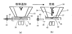
- FIG. 3 schematically shows a main part of the resin coating apparatus 30 according to the present embodiment for spraying a powder resin to a local region, and is quantitatively cut out at a lower end opening 33 of a hopper-shaped tank 31.
- a thermal spray nozzle 32 is provided via a shutter device 35.
- a powder supply device 34 is connected to the tank 31 to supply powder mainly composed of resin to the tank 31.
- a heating means for heating the supplied powder resin to a predetermined temperature can be provided as necessary.
- the hot air generator 40 is preferable.
- the fixed quantity cut-out shutter device 35 includes a rotating body 36 that traverses the lower end opening 33 of the tank 31, faces the lower end opening 33 of the tank 31 to the rotating body 36, and the top reaches the substantially central axis of the rotating body 36.
- a conical depression measuring chamber 37 is provided.
- One end of the rotator 36 is connected to intermittent rotation driving means (not shown), and has a channel 42 having one end connected to a pressurized gas source along the central axis, and the channel is a measuring chamber. It communicates with a pressurized gas supply port 38 formed at the top of 37.
- a supply pipe 43 connected to a compressed air supply source such as a compressor is connected to the flow path 42, and the supply timing of the pressurized gas into the measuring chamber 37 is controlled by an electromagnetic valve 44 provided in the supply pipe. Control.
- the rotating body 36 is intermittently half-rotated and controlled so that the measuring chamber is alternately positioned at the powder measuring position and the pressure feeding position to the spray nozzle.
- a heating gas is supplied to the thermal spray nozzle 32 as a heating means.
- the heated gas is preferably hot air, and the hot air is supplied to the thermal spray nozzle as a heated gas heated to a predetermined temperature by heating means such as electric or gas combustion by a hot air generator 40 connected to an air supply source such as a compressor.
- the thermal spray nozzle 32 has an introduction flow channel 45 for receiving the powder resin from the measuring chamber 37 when the rotating body 36 is rotated to the thermal spray position, and an injection flow channel 46 having a predetermined diameter is formed below the thermal spray nozzle 32. ing. A heating gas is supplied to the injection flow path 46, and the heating gas merges with the powder pressure-fed from the measurement chamber.
- the rotary body 36 is rotatably connected in a sealed state between the tank 31, the quantitative cutout shutter device 35 and the thermal spray nozzle 32 so that the powder does not leak outside.
- the powder resin coating apparatus of the present invention is configured as described above, and performs resin coating by spraying the powder resin onto a predetermined region of the object as follows.
- region of a target object is preheated.
- the preheating is not particularly limited, and various heating methods can be adopted. However, in order to heat with partially simple and inexpensive equipment, hot air is supplied from the preheating nozzle 25 as shown in FIG. It is preferable to spray. Moreover, preheating can also be performed by using hot air from a thermal spray nozzle and delaying resin injection. By preheating the surface to be sprayed, even if the resin sprayed from the spray nozzle is not completely melted, the resin is well welded to the surface of the object, and a resin coating can be intermittently formed at a high speed.
- the resin coating is performed by spraying a powder resin onto the local area of the preheated object with the above coating apparatus.
- the powder resin is supplied into the tank 31 in the state shown in FIG. 3A.
- the powder resin is automatically filled.
- the measuring chamber 37 is reversed as shown in FIG. 3B to face the introduction flow path 45 of the thermal spray nozzle 32, and at the same time, the valve 44 is opened and pressurized air is opened. Is injected into the measuring chamber through the pressurized gas supply port 38, and a certain amount of the resin powder in the measuring chamber joins with the heated gas flowing through the spray passage 46 of the spray nozzle and is sprayed onto the local region of the object.
- the powder provided in the tank as shown in FIG. 4B so that the resin is completely filled in the measuring chamber 37.
- the nozzle 34-1 of the body resin supply device 34 is extended to the immediate upper part of the measuring chamber so as to compress and fill the powder.
- Example 1 (Resin pile on laminated base paper) As shown in FIG. 5, powder resin was sprayed on the front side of the prototype laminated base paper 70 ([front] polyethylene 18 ⁇ m / base paper (300 g / m 2 ) / [back] polyethylene 18 ⁇ m) under the following conditions using the above apparatus.
- Powder resin Low-density polyethylene powder having an average particle size of 120 ⁇ m
- Single powder injection amount about 20 mg
- Distance between thermal spray nozzle and target surface 6mm
- Nozzle outlet hot air temperature 320 ° C
- Preheating Delay before injection 1.5s
- a resin pile 71 having a central coating thickness of 1.1 mm as shown in FIG. 5 could be satisfactorily formed without causing a stringing phenomenon.
- Example 2 (resin pile on a step part) Resin was sprayed in the vicinity of the stepped portion 4 of the opening curled portion 3 of the cup-shaped container 1 by the above apparatus under the following conditions.
- Powder resin Low-density polyethylene powder having an average particle size of 120 ⁇ m
- Single powder injection amount about 25 mg
- Distance between spray nozzle and spray target surface 10mm
- Nozzle outlet hot air temperature 320 ° C
- Preheating Delay before injection 1.5s
- Remarks Reheating with hot air generator
- a resin pile 8 having a coating thickness of 0.3 mm can be satisfactorily formed so as to cover the stepped portion 4. It was.
- the resin melts when the lid material is heat-sealed, so that the weldability with the lid material is further increased without crushing the curled portion, and the sealing performance is improved. And I was able to eliminate the uncomfortable feeling when drinking directly. Also, in the case of an overcap, the stepped portion of the curled portion is eliminated, so that leakage from the curled portion can be prevented.
- Example 3 (Resin coating for the purpose of local modification of an object) Resin coating was performed on the inner peripheral surface of the annular leg portion of the cup-shaped container over the entire circumference under the following conditions.
- Test container cup-shaped container (material: same for trunk and bottom) Material layer structure: Body: (Inner) Polyethylene (20 ⁇ m) // Slash slash paper (250g / m 2 ) Bottom: (inside) polyethylene (40 ⁇ m) // paper 250 g / m 2 // polyethylene (15 ⁇ m) Full capacity: 565 ml, annular leg height: 10 mm
- Anti-burning substance (low dielectric constant material): Calcium carbonate Resin coating film: Width of about 10 mm along the inner circumference of the annular leg portion, film thickness of 1 mm or less A resin coating layer containing an anti-burning substance was formed on the inner circumferential surface of the annular leg.
- the cup-shaped container which necessarily has an annular leg part.
- the present invention is not limited to this, and the present invention can be applied to a variety of structures having a portion that is likely to cause scoring of a microwave-compatible paper-molded container.
- the present invention can reliably and efficiently deposit a resin in a narrow local area in a paper molding container, and can solve the problems of the sealing property of the paper molding container and the occurrence of scorching for a microwave oven, and is inexpensive. With a simple structure, the applicability of the paper-molded container to normal temperature distribution can be increased, and the coating resin can be reliably sprayed on the local region, and the industrial applicability is high.
Landscapes
- Engineering & Computer Science (AREA)
- Mechanical Engineering (AREA)
- Chemical & Material Sciences (AREA)
- Physics & Mathematics (AREA)
- Life Sciences & Earth Sciences (AREA)
- Food Science & Technology (AREA)
- Organic Chemistry (AREA)
- Plasma & Fusion (AREA)
- Chemical Kinetics & Catalysis (AREA)
- Materials Engineering (AREA)
- Metallurgy (AREA)
- Fluid Mechanics (AREA)
- General Physics & Mathematics (AREA)
- Wood Science & Technology (AREA)
- Application Of Or Painting With Fluid Materials (AREA)
- Making Paper Articles (AREA)
- Closures For Containers (AREA)
Abstract
Description
このようなコップ状紙成形体に内容物を充填し密封する場合、カール部の上面に蓋材をヒートシールしている。また、店頭販売等で充填して直ぐ消費される場合は、オーバーキャップを嵌着係合させて販売されている。蓋材をヒートシールする際は、蓋材の熱接着不良を防止するために通常カール部を平坦に潰してフランジ状にして接着面積の増大を図っている。このようなコップ状紙成形体は、直飲み用容器として使用されているが、開口端部に段差部があると口当たりに違和感があり、その上平坦に潰したフランジそのものが口に当たり違和感がある。また、胴部の貼り合せ位置では紙端縁が成形体の内外に露出するので、特に内側に位置する紙端縁は直接内容液と接触して吸湿してしまい、容器の耐水性を劣化させるという問題点がある。また、絞り紙成形体の場合、開口周縁のフランジ部にしわが発生するため、該フランジ面に蓋材をシールした場合に密封性を確保するのが困難であるという問題点がある。 A typical cup-shaped paper molded body as a paper molded body for eating and drinking has a step due to bonding of both ends of the blank to the opening curl portion, and a bonding portion is also formed on the body portion. The paper edge is exposed inside and outside the cup.
When the cup-shaped paper molded body is filled with the contents and sealed, a lid material is heat sealed on the upper surface of the curled portion. In addition, when the product is consumed immediately after being filled in a store or the like, it is sold with an overcap fitted. When heat-sealing the lid material, the curled portion is usually flattened to form a flange to prevent the lid material from being thermally bonded to increase the adhesion area. Such a cup-shaped paper molded body is used as a container for direct drinking, but if there is a step at the opening end, the mouth feels uncomfortable, and the flatly crushed flange itself feels uncomfortable against the mouth. . In addition, since the paper edge is exposed to the inside and outside of the molded body at the bonding position of the body portion, the paper edge located particularly inside is directly in contact with the content liquid and absorbs moisture, thereby deteriorating the water resistance of the container. There is a problem. Further, in the case of the squeezed paper molded product, wrinkles are generated in the flange portion at the periphery of the opening, and thus there is a problem that it is difficult to ensure the sealing performance when the lid material is sealed on the flange surface.
また、他の方法として、溶射ガンにより接着性樹脂粉末を対象物表面にアセチレン、プロパン等による火炎を利用するフレーム溶射で樹脂被覆することも知られている(特許文献7参照)。しかし、この場合も間欠処理やスプレーパターン制御が困難であり、狭領域への確実な溶射被覆は困難であり、且つ対象物や被覆樹脂自体が火炎により熱劣化を起こす恐れがある。 On the other hand, as a means for resin-coating the local area of an object such as a paper-molded container, a method of coating a molten resin by discharging it with a hot melt gun or a hot liner is generally performed. Therefore, there is a problem in that it is difficult to accurately cover a narrow region, resin is wasted, and it is difficult to cycle up. In addition, there are wet methods such as resin solution coating and emulsion coating, but there are problems that the material is limited and the solvent has to be vaporized after coating, and the environmental load of the solvent is high. Furthermore, a method of forming a film by injecting molten resin, which is extruded and melted with a screw while heating a resin raw material in the same manner as an injection molding machine, onto a surface of an object such as metal is formed (Patent) Reference 6). Although this device is suitable for resin coating on the surface of a large object, accurate intermittent injection of a small amount of resin is difficult. For example, a small amount of resin is placed on the stepped portion of an opening curl portion such as a paper cup. However, it is difficult to apply, and it is difficult to reduce the size and speed of the apparatus, and the equipment cost is high.
In addition, as another method, it is also known that an adhesive resin powder is coated on the surface of an object by flame spraying using a flame of acetylene, propane or the like with a spray gun (see Patent Document 7). However, in this case as well, intermittent processing and spray pattern control are difficult, and reliable spray coating in a narrow region is difficult, and there is a possibility that the target object or the coating resin itself may be thermally deteriorated by a flame.
また、搬送ライン上を搬送されて工業的に大量生産される紙成形体に対して、合成樹脂を主体とした樹脂被膜を紙成形体の狭い領域に部分的に間欠的に正確かつ効率的に形成する技術は未だ確立されていないといえる。 In a conventional paper molded body, as described in
Also, for paper compacts that are transported on a transport line and are industrially mass-produced, a resin film mainly composed of synthetic resin is partially intermittently accurately and efficiently in a narrow area of the paper compact. It can be said that the technology to form is not yet established.
本発明の紙成形体は、前記局所部がコップ状紙成形体の開口部周縁のすくなくとも貼り合わせ段差部であり、該段差部へ樹脂盛りがなされて該段差部を埋めるように構成することができる。
また、前記局所部が紙成形体の胴部の貼り合わせ段差部である場合、該段差部への樹脂盛りによって、前記貼り合わせ部の紙端縁を樹脂被覆するように構成することができる。
さらに、前記紙成形容器が紙を主体とする絞り成形体である場合、開口フランジ面全周に前記樹脂盛りを形成することによって、該開口フランジ面のしわを被覆するように構成することができる。
また、前記樹脂盛りは、熱接着性樹脂粉末を溶射して形成された被膜厚さ0.3mm以下であるように構成することもできる。 The paper molded body of the present invention that solves the above-mentioned problems is characterized in that, in the paper molded body having an opening, the resin is deposited by thermal spraying of a coating material made of powder mainly composed of synthetic resin in a local portion. It is what.
The paper molded body of the present invention may be configured such that the local portion is at least a bonding stepped portion at the periphery of the opening of the cup-shaped paper molded body, and the stepped portion is filled with resin to fill the stepped portion. it can.
Moreover, when the said local part is the bonding level | step difference part of the trunk | drum of a paper molded object, it can comprise so that the paper edge of the said bonding part may be resin-coated with the resin pile to this level | step-difference part.
Further, when the paper molding container is a drawn molded body mainly made of paper, it can be configured to cover the wrinkles of the opening flange surface by forming the resin pile all around the opening flange surface. .
Moreover, the said resin pile can also be comprised so that the film thickness of 0.3 mm or less formed by thermal spraying the heat-adhesive resin powder.
前記局所領域は、コップ状紙成形容器の場合、電子レンジ加熱時に焦げが発生しやすい環状脚部内周面とする。
前記樹脂被覆層は、樹脂粉末に焦げ防止物質粉末を混合した粉体を溶射して形成することによって、所定位置に少ない被覆材料で効果的に被覆層を形成できる。
前記樹脂粉末は、その種類は限定されないが、粒径30~300μmのポリエチレンやポリプロピレン等のポリオレフィン樹脂粉末やPET、PEN、PLA、PBT等のポリエステル樹脂粉末が効果的に採用できる。
一方、焦げ防止物質粉末としては、安価な低誘電率物質である炭酸カルシウムやタルクが採用できる。 In the case where the paper molding container of the present invention is a microwave molding-compatible paper molding container, by forming a resin coating layer containing a non-burning substance in a local region of the paper container, generation of scorching during microwave heating is prevented. can do.
In the case of a cup-shaped paper molding container, the local region is an inner circumferential surface of an annular leg portion that is likely to be burned during microwave heating.
The resin coating layer can be effectively formed with a small amount of coating material at a predetermined position by thermal spraying a powder obtained by mixing a non-burning substance powder with a resin powder.
The type of the resin powder is not limited, but polyolefin resin powders such as polyethylene and polypropylene having a particle size of 30 to 300 μm and polyester resin powders such as PET, PEN, PLA, and PBT can be effectively employed.
On the other hand, as the non-burning substance powder, calcium carbonate and talc, which are inexpensive low dielectric constant substances, can be used.
前記溶射は、前記粉体を定量に切り出し加圧ガスにより圧送し加熱ガスに合流させて間欠的に前記局所領域に溶射することによって、対象物に少量ずつ定量の樹脂被覆を繰り返し行うことができる。
前記粉体の加熱は熱風により前記合成樹脂の融点近傍で加熱し部分的に溶融させることが望ましい。さらに、前記対象物は、被覆する局所領域を予備加熱することによって、完全に溶融した状態での噴射でなく、噴射された樹脂粉末は対象物の表面で完全に溶融して対象物表面を被覆するので、糸引き現象の発生がなく間欠溶射のサイクルアップが可能であり被覆効率を高めることができる。 The local region resin coating method of the present invention that solves the above problem is a coating method in which a local region of an object is coated with a coating material mainly composed of a synthetic resin, and the powder mainly composed of a synthetic resin is intermittently applied. Thermal spraying is performed on the local region.
In the thermal spraying, the powder can be repeatedly applied in a small amount to the target by cutting the powder into a fixed amount, pumping it with a pressurized gas, and joining the heated gas to intermittently spray the local region. .
The powder is preferably heated by hot air near the melting point of the synthetic resin and partially melted. Furthermore, the object is not heated in a completely melted state by preheating the local area to be coated, but the injected resin powder is completely melted on the surface of the object to cover the surface of the object. Therefore, there is no occurrence of the stringing phenomenon, the cycle of intermittent spraying can be increased, and the coating efficiency can be increased.
また、本発明をコップ状紙成形体の開口周縁部の貼り合わせ段差部に適用して、該段差部に少量の樹脂盛りをすることによって、該容器から内容物を直飲みする場合の口当たりを良くすると共に、蓋材をヒートシールする際の該段差部でのシール性が向上し密封性を高めることができ、紙成形体を内容物が常温保存できる密封容器への適用性を高めることができる。また該容器にオーバーキャップを被せて密封する際の、前記段差部からの漏洩を効果的に防ぐことができる。
さらに、本発明を紙成形体の貼り合わせ部等の露出する紙端縁に適用して、該露出紙端縁を効果的に樹脂被覆することができ、露出紙端縁から内容液等の吸湿を防止して耐水性を高めることができる。
さらに、また本発明を紙を主体とする絞り成形体の開口フランジ面に適用することによって、フランジの皺を被覆できて、ヒートシール蓋材の熱溶着性を高め密封性を高めることができる。
前記樹脂盛りを、熱接着性樹脂の粉末を溶射して形成した平均被膜厚さ0.3mm以下に構成することによって、糸引きが無く、少ない樹脂材料で効率的に形成できる。 According to the present invention, the blank base material is specially processed to solve the problems caused by the bonded portion of the paper molded body having openings and the occurrence of wrinkles simply by applying a resin pile locally to the paper molded body. Therefore, it is possible to obtain a paper molded body that can be easily solved at low cost and has excellent sealing properties.
In addition, by applying the present invention to a bonding step portion at the peripheral edge of the opening of the cup-shaped paper molded body, and adding a small amount of resin to the step portion, the mouthfeel when directly drinking the contents from the container is increased. As well as improving the sealing performance at the stepped portion when heat-sealing the lid material, the sealing performance can be improved, and the applicability to a sealed container in which the contents of the paper molded body can be stored at room temperature can be improved. it can. In addition, leakage from the step portion when the container is sealed with an overcap can be effectively prevented.
Furthermore, the present invention can be applied to an exposed paper edge such as a bonded portion of a paper molded body, and the exposed paper edge can be effectively resin-coated, and moisture absorption of content liquid or the like can be performed from the exposed paper edge. Water resistance can be improved.
Furthermore, by applying the present invention to the opening flange surface of the drawn molded body mainly composed of paper, the flange flange can be covered, and the heat-sealing property of the heat-sealing lid material can be enhanced and the sealing performance can be enhanced.
By forming the resin pile with an average film thickness of 0.3 mm or less formed by spraying a thermal adhesive resin powder, there is no stringing and it can be efficiently formed with a small resin material.
そして、コップ状紙成形容器の場合、環状脚部内周面に焦げ防止物質を含有する樹脂被覆層を形成するのみで、従来のコップ状成形容器の底部形状を変更することなく、容易に焦げの発生を防止できる。
さらに、前記樹脂被覆層は、プラスチック粉末に焦げ防止粉末を混合した粉体を溶射して形成することによって、環状脚部内周面に確実に且つ安価に焦げ防止層を形成することができる。前記焦げ防止物質粉末として比誘電率2以下の無機物を採用することによって、効果的に焦げ防止層を形成することができる。 In addition, when the paper molding container of the present invention is compatible with microwave heating, it is easy to change the basic structure of the conventional paper molding container by forming a resin coating layer containing a non-burning substance in the local region. By such means, it is possible to easily prevent the occurrence of scorching during microwave heating.
And in the case of a cup-shaped paper-molded container, it is easy to burn without changing the bottom shape of the conventional cup-shaped molded container by simply forming a resin coating layer containing a scorching preventing substance on the inner peripheral surface of the annular leg. Occurrence can be prevented.
Furthermore, the resin coating layer can be formed reliably and inexpensively on the inner peripheral surface of the annular leg by spraying a powder obtained by mixing a non-burning powder with a plastic powder. By using an inorganic substance having a relative dielectric constant of 2 or less as the anti-burning substance powder, a non-burning layer can be formed effectively.
そして、合成樹脂を主体とする粉体を定量に間欠的に切り出して溶射することにより、溶着効率の高い粒径の小さい材料を小面積に溶射することが可能となり、最小限の使用材料で効率良く樹脂被覆でき、かつハイサイクル化が可能である。
さらに、溶射は熱風で合成樹脂紛体をその融点近傍で加熱し部分的に溶融させることによって、対象物に付着後に溶融するので樹脂の糸引き現象がなくなり、高速の間欠噴射が正確にできる。
そして、対象物は樹脂被覆する局所領域を予備加熱することにより、融点近傍で加熱し部分的に溶融させた状態で溶射された樹脂紛体が局所領域で効率的に溶着することができる。
また、本発明の被覆方法を、開口部を有する容器の開口カール部の貼り合せ段差部に適用して、該段差部に少量の樹脂盛りをすることができ、該容器から内容物を直飲みする場合の口当たりを良くすることができると共に、蓋材をヒートシールする際の該段差部でのシール性を高めることができる。また該容器にオーバーキャップを被せて密封する際の、前記段差部からの漏洩を効果的に防ぐことができる。
さらに、本発明の被覆方法を、紙製容器の重ね合せ部等の露出紙端に適用して、該露出紙端を効果的に樹脂被覆することができ、露出紙端から内容液等の吸湿を防止して耐水性を高めることができる。
また、本発明の被覆方法を、剛性の低い紙成形体に適用して、補強材としての局所的な肉盛りを追加することができ、成形体の剛性や保形性を向上することができる。
さらに、本発明の被覆方法を、例えば該粉体樹脂に無機物等の粉末を混合して、紙製容器を電子レンジで加熱する場合に焦げが発生しやすい局所に適用することによって、該局所を焦げが発生しにくいように改質することができる。 According to the coating method of the present invention, resin coating can be accurately and efficiently performed even in a small area by intermittently spraying a powder mainly composed of synthetic resin on a local region.
In addition, by intermittently cutting and spraying a powder mainly composed of synthetic resin, it becomes possible to spray a small particle size material with high welding efficiency to a small area, and it is efficient with the minimum amount of material used. The resin can be well coated and high cycle can be achieved.
Further, in the thermal spraying, the synthetic resin powder is heated in the vicinity of its melting point with hot air and partially melted to melt after adhering to the object, so that the resin stringing phenomenon is eliminated and high-speed intermittent injection can be performed accurately.
The object is preheated in the local region to be coated with the resin, so that the resin powder sprayed in a state of being partially melted by heating near the melting point can be efficiently welded in the local region.
In addition, the coating method of the present invention can be applied to a bonding step portion of an opening curl portion of a container having an opening portion so that a small amount of resin can be deposited on the step portion, and the contents can be directly taken from the container. In addition, it is possible to improve the mouth-feel and to improve the sealing performance at the stepped portion when the lid material is heat-sealed. In addition, leakage from the step portion when the container is sealed with an overcap can be effectively prevented.
Furthermore, the coating method of the present invention can be applied to the exposed paper edge such as the overlapping portion of the paper container so that the exposed paper edge can be effectively resin-coated, and moisture from the exposed paper edge can be absorbed. Water resistance can be improved.
Further, the coating method of the present invention can be applied to a paper molded body having low rigidity to add local build-up as a reinforcing material, and the rigidity and shape retention of the molded body can be improved. .
Further, by applying the coating method of the present invention, for example, by mixing a powder such as an inorganic substance in the powder resin, and applying it to a region where scorching is likely to occur when a paper container is heated in a microwave oven, It can be modified so that it does not easily burn.
また、本発明の被覆装置は、定量切出しシャッター装置を備えることにより、簡単な機構で小量の粉体樹脂であっても正確に計量することができ、かつ間欠的に高速で行うことができる。その結果、滑落性が乏しくなる粒径の小さい粉体の適用も可能である。
また、加熱ガスを熱風とすることによって、火炎を使用しないで溶射することができ、対象物や被覆樹脂自体の熱的影響を緩和することができる。 The coating apparatus of the present invention has a simple structure and can be reduced in size, can be easily and inexpensively incorporated into a normal production line, and even if the sprayed area is a small area, a small amount of powder The resin can be sprayed accurately and intermittently, and the material used can be reduced.
In addition, the coating apparatus of the present invention includes a quantitative cut-out shutter device, so that even a small amount of powder resin can be accurately measured with a simple mechanism and can be intermittently performed at high speed. . As a result, it is also possible to apply a powder having a small particle size that makes sliding property poor.
In addition, by using hot air as the heated gas, thermal spraying can be performed without using a flame, and the thermal influence of the object and the coating resin itself can be mitigated.
2 胴部
3 開口カール部
4 段差部
5 胴部貼り合わせ部
6 紙端縁
7 環状脚部
8,9,13 樹脂盛り
10 絞り成形容器
12 フランジ面
14 皺
25 予備加熱ノズル
30 被覆装置
31 タンク
32 溶射ノズル
33 下端開口部
34 粉体供給装置
35 定量切り出しシャッター装置
36 回転体
37 計量室
38 ガス供給口
40 熱風発生器
42 流路
43 供給管路
44 電磁バルブ
45 導入流路
46 噴射流路
52 折返し片
57 底板
58 環状屈曲部
60 無機物混合樹脂層
70 試作ラミネート原紙
71 樹脂盛り DESCRIPTION OF
図1は、本発明の実施形態に係る紙成形体としてのコップ状容器を示す。該コップ状容器1は、胴部2となる扇形状のブランクの両端縁を貼り合わせて接着して円錐状に成形し、その上端部をカール成形して開口端部とし、下端部Bの段面を図1(d)に示すように内側に折り返して折り返し片52を形成し、その間に断面コ字状に絞り成形した底板57の環状屈曲部58を圧着した環状脚部7となっており、開口カール部3のA部には図1(b)に拡大して示すようにブランク両端縁の貼り合わせによる段差部4ができている。また、胴部には貼り合わせ部5ができ、該貼り合わせ部の両端縁には紙端がコップ内側及び外側で露出している。以上の構造は、従来周知のコップ状紙成形容器と同様である。 Hereinafter, embodiments of a paper molding container according to the present invention will be described in detail with reference to the drawings.
FIG. 1 shows a cup-shaped container as a paper molded body according to an embodiment of the present invention. The cup-shaped
コップ状紙成形容器のカール部の段差部4という狭い領域に的確に樹脂盛りをすることは困難であるが、本実施形態では、図3に模式的に示す樹脂溶射装置により、粉体樹脂を間欠的に溶射することにより、カール部の段差部4に良好に樹脂盛りをすることができ、上記問題点を原紙端縁自体を特別な加工を施すことなく、簡単な方法により解決することができた。 In such a cup-shaped paper molding container, in order to eliminate the above-mentioned poor sealing due to the stepped
Although it is difficult to accurately deposit the resin in a narrow region called the stepped
ここで、合成樹脂としては、熱可塑性樹脂であれば特に限定されないが、高-中-低密度ポリエチレン、ポリプロピレン等のポリオレフィン、PET、PEN、PLA、PBT等のポリエステル樹脂の一種または複数種の樹脂粉末が採用できる。また、焦げ防止粉末物質としては、比誘電率の低い物質として、例えば炭酸カルシウム、タルク等が採用できる。これにより、環状脚部でのマイクロ波の吸収による発熱が減少し、焦げの発生を防止できる。 Although not limited to the following as a powder used for this invention, the material which has easy-adhesion with respect to the paper molding container which has paper as a main component is used. In general paper-molded containers, the base paper substrate is coated with a resin, and it is easy to use a resin of the same type as the surface resin layer or a resin having a lower melting point than the surface resin layer. Is preferable.
Here, the synthetic resin is not particularly limited as long as it is a thermoplastic resin, but is a polyolefin such as high-medium-low density polyethylene and polypropylene, or one or more kinds of polyester resins such as PET, PEN, PLA and PBT. Powder can be used. In addition, as the non-burning powder material, for example, calcium carbonate, talc or the like can be adopted as a material having a low relative dielectric constant. As a result, heat generation due to absorption of microwaves in the annular leg portion is reduced, and the occurrence of scorching can be prevented.
以上のような方法で環状脚部内周面に樹脂被覆をすることによって、糸引き現象が生じることなく所定の小領域に樹脂被覆を的確にすることができ、使用材料を最小限にすることができる。 The formation of the resin coating layer containing the non-burning substance in the local region may be performed by hot melt, hot runner, flame spraying, or the like. However, as in this embodiment, in order to form a container with a very small coating area and a high-speed production line of a container with a small amount of resin, the stringing phenomenon of the coating resin occurs in any of the above methods, and thus the cycle up is limited. It is difficult to apply accurately. In order to overcome this, in the present embodiment, a pre-heating step and a resin spraying step are provided as post-processing steps on the cup-shaped container that is molded and transported in the production line, and hot air is applied to the resin application region in the pre-heating step. Was sprayed to preheat the inner peripheral surface of the annular leg portion to near the melting point of the coating resin, and then the resin powder was sprayed onto the portion in a resin spraying step. As described above, the thermal spraying of the resin powder is performed by using a powder resin powder obtained by mixing a synthetic resin powder having a particle size of 30 to 300 μm and a non-burning substance powder as a raw material, and heating the raw material to a melting temperature of the resin or lower. It can be formed by thermally spraying the resin material intermittently or continuously on the inner peripheral surface of the annular leg portion with a heating gas (hot air in the present embodiment) by an injection nozzle.
By coating the inner circumferential surface of the annular leg with the above-described method, the resin coating can be accurately applied to a predetermined small area without causing the stringing phenomenon, and the material used can be minimized. it can.
本発明は、対象物の小さい領域に少ない樹脂で、糸引き現象等を生じることなく高速でかつ確実に樹脂被覆を可能にする方法として、本発明では合成樹脂を主体とした粉体を、定量的に切り出し合成樹脂の融点近傍まで加熱して間欠的に、局所領域に繰り返し溶射するようにした。合成樹脂粉体としては、該合成樹脂で被覆する局所の用途・目的に応じて樹脂材料及びその粒径が選択され、例えばコップの開口カール部の段差領域に樹脂盛りのために溶射する場合は、段差部を無くして口当たりを良くし、かつ蓋材とヒートシールして密封性を向上させるために、ポリエチレン等のヒートシール性樹脂粉末を採用する。 Hereinafter, an embodiment of the coating method and coating apparatus of the present invention capable of accurately depositing a small amount of resin locally on the paper molding container will be described in detail with reference to FIGS.
In the present invention, as a method for enabling high-speed and reliable resin coating with a small amount of resin in a small area of an object without causing a stringing phenomenon or the like, in the present invention, a powder mainly composed of a synthetic resin is quantified. The heat was cut to near the melting point of the synthetic resin and intermittently sprayed repeatedly on the local area intermittently. As the synthetic resin powder, the resin material and its particle size are selected according to the local application / purpose covered with the synthetic resin. For example, when spraying in the stepped area of the opening curl portion of the cup for resin deposition In order to improve the sealing performance by eliminating the stepped portion and heat sealing with the lid material, heat sealing resin powder such as polyethylene is employed.
溶射ノズル32には加熱手段として加熱ガスが供給される。加熱ガスとしては、熱風が望ましく、コンプレッサー等の空気供給源に連結された熱風発生器40により電気的或いはガス燃焼等の加熱手段で所定温度に加熱された加熱ガスとして熱風が溶射ノズルに供給される。 The fixed quantity cut-
A heating gas is supplied to the
まず、対象物の樹脂被覆予定領域を予備加熱する。予備加熱は、種々の加熱方法が採用でき特に限定されるものではないが、部分的に簡易でかつ安価な設備で加熱するには図7(a)に示すように予備加熱ノズル25から熱風を吹き付けて行うのが好ましい。また、溶射ノズルからの熱風を利用し、樹脂の噴射を遅延させることで予備加熱することもできる。溶射対象面を予備加熱することによって、溶射ノズルから噴射された樹脂が完全に溶融しなくても対象物面に樹脂が良好に溶着し、間欠的に高速で樹脂被覆を形成できる。 The powder resin coating apparatus of the present invention is configured as described above, and performs resin coating by spraying the powder resin onto a predetermined region of the object as follows.
First, the resin coating planned area | region of a target object is preheated. The preheating is not particularly limited, and various heating methods can be adopted. However, in order to heat with partially simple and inexpensive equipment, hot air is supplied from the preheating
図5に示すように試作ラミネート原紙70([表]ポリエチレン18μm / 原紙(300g/m2 )/[裏]ポリエチレン18μm)の表側に、上記装置を用いて次の条件で粉末樹脂を溶射した。
粉体樹脂:平均粒径120μmの低密度ポリエチレン粉体
1回の粉体噴射量:約20mg
溶射ノズルと溶射対象面間の距離:6mm
ノズル出口熱風温度:320℃
予備加熱:噴射前遅延1.5s
その結果、図5のような中央部被覆膜厚1.1mmの樹脂盛り71を糸引き現象を生じることなく良好に形成することができた。 Example 1: (Resin pile on laminated base paper)
As shown in FIG. 5, powder resin was sprayed on the front side of the prototype laminated base paper 70 ([front] polyethylene 18 μm / base paper (300 g / m 2 ) / [back] polyethylene 18 μm) under the following conditions using the above apparatus.
Powder resin: Low-density polyethylene powder having an average particle size of 120 μm Single powder injection amount: about 20 mg
Distance between thermal spray nozzle and target surface: 6mm
Nozzle outlet hot air temperature: 320 ° C
Preheating: Delay before injection 1.5s
As a result, a
コップ状容器1の開口カール部3の段差部4近傍に前記装置により次の条件で樹脂を溶射した。
粉体樹脂:平均粒径120μmの低密度ポリエチレン粉体
1回の粉体噴射量:約25mg
溶射ノズルと溶射対象面間の距離:10mm
ノズル出口熱風温度:320℃
予備加熱:噴射前遅延1.5s
備考:熱風発生器による再加熱を実施
その結果、図6(b-1)に示すように段差部4を覆うように被覆膜厚0.3mmの樹脂盛り8を良好に形成することができた。
このように、段差部に樹脂盛りをすることによって、蓋材をヒートシールする際に該樹脂が溶融しカール部を圧潰しなくても蓋材との溶着性がより高まり、密封性が向上すると共に直飲時の違和感をなくすことができた。また、オーバーキャップの場合も、カール部の段差部がなくなるため、そこからの洩れを防止できる。 Example 2: (resin pile on a step part)
Resin was sprayed in the vicinity of the stepped
Powder resin: Low-density polyethylene powder having an average particle size of 120 μm Single powder injection amount: about 25 mg
Distance between spray nozzle and spray target surface: 10mm
Nozzle outlet hot air temperature: 320 ° C
Preheating: Delay before injection 1.5s
Remarks: Reheating with hot air generator As a result, as shown in FIG. 6 (b-1), a
In this way, by depositing the resin on the stepped portion, the resin melts when the lid material is heat-sealed, so that the weldability with the lid material is further increased without crushing the curled portion, and the sealing performance is improved. And I was able to eliminate the uncomfortable feeling when drinking directly. Also, in the case of an overcap, the stepped portion of the curled portion is eliminated, so that leakage from the curled portion can be prevented.
コップ状容器の環状脚部内周面に全周にわたって以下の条件で樹脂被覆を行った。
供試容器:コップ状容器(材質:胴部及び底部とも同じ)
材質層構成:
胴部:(内)ポリエチレン(20μm)//スラッシュスラッシュ紙(250g/m2)
底部:(内)ポリエチレン(40μm)//紙250g/m2//ポリエチレン(15μm)
満杯内容量:565ml、環状脚部高さ:10mm
溶射条件:
粉体樹脂:平均粒径120μmの粉体ポリエチレン
焦げ防止物質(低誘電率材料):炭酸カルシウム
樹脂塗膜:環状脚部内周全周に沿って幅約10mm、被膜厚さ1mm以下
以上のようにして環状脚部内周面に焦げ防止物質を含有する樹脂被覆層を形成した。コップ状容器の焦げの発生状況を確認するために、次のような試験を行った。
容器充填内容物:水330ml
電子レンジ出力:500W
加熱時間:6min
上記加熱条件は、内容物(うどん食品)を食するのに最適な通常の加熱温度である。
焦げの発生状況:被覆層を形成した本実施例の容器の方が糸底部に発生した焦げの色が、比較例として被覆層を設けていない容器よりも薄く範囲が狭かった。 Example 3: (Resin coating for the purpose of local modification of an object)
Resin coating was performed on the inner peripheral surface of the annular leg portion of the cup-shaped container over the entire circumference under the following conditions.
Test container: cup-shaped container (material: same for trunk and bottom)
Material layer structure:
Body: (Inner) Polyethylene (20μm) // Slash slash paper (250g / m 2 )
Bottom: (inside) polyethylene (40 μm) // paper 250 g / m 2 // polyethylene (15 μm)
Full capacity: 565 ml, annular leg height: 10 mm
Thermal spraying conditions:
Powder resin: Powdered polyethylene with an average particle size of 120 μm Anti-burning substance (low dielectric constant material): Calcium carbonate Resin coating film: Width of about 10 mm along the inner circumference of the annular leg portion, film thickness of 1 mm or less A resin coating layer containing an anti-burning substance was formed on the inner circumferential surface of the annular leg. In order to confirm the occurrence of scorching of the cup-shaped container, the following test was conducted.
Container filling contents: 330 ml of water
Microwave oven output: 500W
Heating time: 6 min
The said heating conditions are the normal heating temperature optimal for eating the contents (Udon food).
Situation of scoring: The container of the present example in which the coating layer was formed was thinner in the color of the scoring color generated at the bottom of the yarn than the container without the coating layer as a comparative example.
Claims (14)
- 開口部を有する紙成形体において、局所部に合成樹脂を主体とする粉体からなる被覆材料の溶射による樹脂盛りがなされていることを特徴とする紙成形体。 A paper molded body having an opening, wherein the resin molding is formed by thermal spraying of a coating material made of powder mainly composed of synthetic resin in a local portion.
- 前記局所部がコップ状紙成形体の開口部周縁のすくなくとも貼り合わせ段差部であり、前記樹脂盛りによって前記段差部を埋めていることを特徴とする請求項1に記載の紙成形体。 2. The paper molded body according to claim 1, wherein the local portion is at least a bonding step portion at the periphery of the opening of the cup-shaped paper molded body, and the step portion is filled with the resin pile.
- 前記局所部が紙成形体の胴部の貼り合わせ段差部であり、前記樹脂盛りによって、前記貼り合わせ部の紙端縁を被覆していることを特徴とする請求項1に記載の紙成形体。 2. The paper molded body according to claim 1, wherein the local portion is a bonding stepped portion of a body portion of the paper molded body, and the resin edge covers a paper edge of the bonding portion. .
- 前記紙成形体が紙を主体とする絞り成形体であり、前記局所部が開口フランジ面全周であり、前記樹脂盛りによって該開口フランジ面のしわを被覆しているものであることを特徴とする請求項1に記載の紙成形体。 The paper molded body is a drawn molded body mainly made of paper, the local portion is the entire circumference of the opening flange surface, and the wrinkles of the opening flange surface are covered with the resin piling. The paper molded body according to claim 1.
- 前記樹脂盛りが、熱接着性樹脂の粉末を溶射して形成された平均被膜厚さ0.3mm以下である請求項1に記載の紙成形体。 The paper molded body according to claim 1, wherein the resin pile has an average film thickness of 0.3 mm or less formed by thermal spraying a powder of a heat-adhesive resin.
- 前記紙成形体が電子レンジ加熱対応の紙成形容器であって、該紙成形容器の局所領域に焦げ防止物質を含有する樹脂被覆層を形成してなることを特徴とする請求項1に記載の紙成形体。 The said paper molded object is a paper molding container corresponding to a microwave oven heating, Comprising: The resin coating layer containing a non-burning substance is formed in the local area | region of this paper molding container. Paper molded body.
- 前記樹脂被覆層は、樹脂粉末に焦げ防止物質粉末を混合した粉体を溶射して形成したものである請求項6に記載の紙成形体。 The paper molded body according to claim 6, wherein the resin coating layer is formed by spraying a powder obtained by mixing a non-burning substance powder with a resin powder.
- 前記焦げ防止物質粉末が比誘電率2以下の無機物である請求項7に記載の紙成形体。 The paper molded body according to claim 7, wherein the non-burning substance powder is an inorganic substance having a relative dielectric constant of 2 or less.
- 対象物の局所領域を合成樹脂を主体とする被覆材料で被覆する被覆方法であって、前記被覆材料が合成樹脂を主体とした粉体であり、該粉体を間欠的に前記局所領域に溶射することを特徴とする被覆方法。 A coating method for coating a local region of an object with a coating material mainly composed of a synthetic resin, wherein the coating material is a powder mainly composed of a synthetic resin, and the powder is intermittently sprayed on the local region. A coating method characterized by:
- 前記溶射は、前記粉体を定量に切り出し加圧ガスにより圧送し加熱ガスに合流させて間欠的に前記局所領域に溶射する請求項9に記載の被覆方法。 10. The coating method according to claim 9, wherein the thermal spraying is performed by intermittently spraying the powder onto the local region intermittently by cutting the powder into a fixed amount, pumping it with a pressurized gas, and joining the heated gas.
- 前記加熱ガスは熱風であり前記合成樹脂粉体を融点近傍で加熱し部分的に溶融させる請求項10に記載の被覆方法。 The coating method according to claim 10, wherein the heated gas is hot air, and the synthetic resin powder is heated in the vicinity of a melting point to be partially melted.
- 前記対象物は、被覆する局所領域が予備加熱される請求項9に記載の被覆方法。 The coating method according to claim 9, wherein the object is preheated in a local region to be coated. *
- 対象物の局所領域を合成樹脂を主体とする被覆材料で被覆する被覆装置であって、前記被覆材料が粉体であり、該粉体が供給されるタンク、該タンクの下端と連通した溶射ノズル、前記タンクの下端開口部と前記溶射ノズルとの間に設けられた定量切り出しシャッター装置とを備えてなり、前記タンクから定量の粉体を前記定量切り出しシャッター装置で切り出して加熱ガスに合流させ、前記溶射ノズルから溶射するようにしてなることを特徴とする被覆装置。 A coating apparatus for coating a local area of an object with a coating material mainly composed of a synthetic resin, wherein the coating material is powder, a tank to which the powder is supplied, and a thermal spray nozzle communicating with a lower end of the tank , Comprising a quantitative cutout shutter device provided between the lower end opening of the tank and the thermal spray nozzle, cut a fixed amount of powder from the tank with the quantitative cutout shutter device, and merged with the heated gas, The coating apparatus is characterized by spraying from the spray nozzle.
- 前記定量切り出しシャッター装置は、前記タンクの出口開口部を横切る回転体からなり、該回転体に前記タンクの出口開口部に面する計量室が設けられると共に、該計量室のガス供給口に連通し該計量室に加圧ガスを供給するバルブを有してなり、前記回転体は、計量位置と溶射位置との間を間欠回転可能であり、計量位置で前記タンクの出口開口部に面して定量の粉体を計量し、噴射位置で前記計量室が前記溶射ノズルに面し、前記バルブから前記計量室に加圧ガスが供給されて前記粉体を前記溶射ノズルに圧送する請求項13に記載の被覆装置。 The quantitative cut-out shutter device comprises a rotating body that traverses the outlet opening of the tank. The rotating body is provided with a measuring chamber facing the outlet opening of the tank, and communicates with a gas supply port of the measuring chamber. A valve for supplying pressurized gas to the metering chamber, the rotating body being capable of intermittent rotation between the metering position and the spraying position, facing the outlet opening of the tank at the metering position; 14. The method according to claim 13, wherein a predetermined amount of powder is measured, the measuring chamber faces the spray nozzle at an injection position, and pressurized gas is supplied from the valve to the measuring chamber to press the powder to the spray nozzle. The coating apparatus as described.
Priority Applications (5)
| Application Number | Priority Date | Filing Date | Title |
|---|---|---|---|
| EP15800664.3A EP3150502A4 (en) | 2014-05-30 | 2015-05-29 | Shaped paper article, localized-region coating method, and coating device |
| US15/314,578 US20170191151A1 (en) | 2014-05-30 | 2015-05-29 | Formed paper article, local region coating method, and coating device |
| KR1020187004758A KR101894755B1 (en) | 2014-05-30 | 2015-05-29 | Shaped paper article, localized-region coating method, and coating device |
| CN201580027343.XA CN106414252B (en) | 2014-05-30 | 2015-05-29 | Paper formed body and regional area coating method and coating device |
| KR1020167033841A KR101877275B1 (en) | 2014-05-30 | 2015-05-29 | Shaped paper article, localized-region coating method, and coating device |
Applications Claiming Priority (6)
| Application Number | Priority Date | Filing Date | Title |
|---|---|---|---|
| JP2014-112615 | 2014-05-30 | ||
| JP2014112616A JP6488560B2 (en) | 2014-05-30 | 2014-05-30 | Microwave-compatible paper molding container |
| JP2014-112616 | 2014-05-30 | ||
| JP2014112617A JP6409340B2 (en) | 2014-05-30 | 2014-05-30 | Resin coating method and apparatus |
| JP2014112615A JP6488559B2 (en) | 2014-05-30 | 2014-05-30 | Paper molding |
| JP2014-112617 | 2014-05-30 |
Publications (1)
| Publication Number | Publication Date |
|---|---|
| WO2015182760A1 true WO2015182760A1 (en) | 2015-12-03 |
Family
ID=54699080
Family Applications (1)
| Application Number | Title | Priority Date | Filing Date |
|---|---|---|---|
| PCT/JP2015/065631 WO2015182760A1 (en) | 2014-05-30 | 2015-05-29 | Shaped paper article, localized-region coating method, and coating device |
Country Status (5)
| Country | Link |
|---|---|
| US (1) | US20170191151A1 (en) |
| EP (1) | EP3150502A4 (en) |
| KR (2) | KR101877275B1 (en) |
| CN (2) | CN106414252B (en) |
| WO (1) | WO2015182760A1 (en) |
Cited By (2)
| Publication number | Priority date | Publication date | Assignee | Title |
|---|---|---|---|---|
| WO2018110488A1 (en) * | 2016-12-15 | 2018-06-21 | 東洋製罐グループホールディングス株式会社 | Paper container and barrel member blank |
| CN115870189A (en) * | 2022-12-30 | 2023-03-31 | 东莞市新唛标签制品有限公司 | Method for locally coating hot melt adhesive on sealing cover of vegetable box |
Families Citing this family (7)
| Publication number | Priority date | Publication date | Assignee | Title |
|---|---|---|---|---|
| EP3261942B1 (en) * | 2015-02-27 | 2019-12-18 | Graphic Packaging International, LLC | Container with coating |
| US20200040214A1 (en) | 2018-08-01 | 2020-02-06 | The Boeing Company | Thermoplastic Coating Formulations For High-Velocity Sprayer Application and Methods For Applying Same |
| US11136480B2 (en) * | 2018-08-01 | 2021-10-05 | The Boeing Company | Thermal spray plastic coating for edge sealing and fillet sealing |
| US11767436B2 (en) | 2018-08-01 | 2023-09-26 | The Boeing Company | Thermal and cold spray plastic coating covering vehicle fasteners inside fuel tank for lightning strike and other electromagnetic protection |
| CN113165274B (en) * | 2018-12-19 | 2023-07-25 | 雀巢产品有限公司 | Method for producing airtight disposable food containers using a contoured sealing head with ribs |
| US11591103B2 (en) | 2019-03-28 | 2023-02-28 | The Boeing Company | Multi-layer thermoplastic spray coating system for high performance sealing on airplanes |
| WO2021002113A1 (en) * | 2019-07-02 | 2021-01-07 | 東罐興業株式会社 | Paper container |
Citations (4)
| Publication number | Priority date | Publication date | Assignee | Title |
|---|---|---|---|---|
| JPS5878743A (en) * | 1982-10-21 | 1983-05-12 | 太平洋セメント株式会社 | Manufacture of paper vessel |
| JPS6350265B2 (en) * | 1979-11-19 | 1988-10-07 | Toyo Seikan Kaisha Ltd | |
| JPH09201833A (en) * | 1996-01-26 | 1997-08-05 | Mitsubishi Heavy Ind Ltd | Plastic flame-coating molding machine and flame-coating molding |
| JP2008105749A (en) * | 2006-09-29 | 2008-05-08 | Dainippon Printing Co Ltd | Molded resin container for use in microwave oven and molded container containing liquid food product for microwave oven heating |
Family Cites Families (22)
| Publication number | Priority date | Publication date | Assignee | Title |
|---|---|---|---|---|
| US3909068A (en) * | 1974-01-04 | 1975-09-30 | Eppco | Powder feeder |
| US3913795A (en) * | 1974-07-29 | 1975-10-21 | Eppco | Pulsating powder metering and dispensing device |
| US4163812A (en) * | 1974-09-03 | 1979-08-07 | W. R. Grace & Co. | Container coating method |
| JPH0615050B2 (en) * | 1986-02-05 | 1994-03-02 | ノードソン株式会社 | Intermittent spray application method of powder and granules and its gun |
| DE3640906C2 (en) | 1986-11-29 | 1995-05-24 | Utp Schweismaterial Gmbh & Co | Process for applying solvent-free adhesives in powder form in the initial state |
| EP0484533B1 (en) * | 1990-05-19 | 1995-01-25 | Anatoly Nikiforovich Papyrin | Method and device for coating |
| JPH04367474A (en) * | 1991-06-06 | 1992-12-18 | Kuwabara Yasunaga | Heat-resistant packaging container |
| US5879753A (en) * | 1997-12-19 | 1999-03-09 | United Technologies Corporation | Thermal spray coating process for rotor blade tips using a rotatable holding fixture |
| JP2002264918A (en) | 2001-03-08 | 2002-09-18 | Toppan Printing Co Ltd | Cup-formed container with opening reinforcing ring and manufacturing method therefor |
| JP2003012016A (en) * | 2001-06-29 | 2003-01-15 | Toppan Printing Co Ltd | Environment-protecting paper cup and its lid |
| JP4849499B2 (en) | 2001-09-21 | 2012-01-11 | 東罐興業株式会社 | Microwave oven heated paper container and manufacturing method thereof |
| JP3984472B2 (en) | 2001-12-21 | 2007-10-03 | 大日本印刷株式会社 | Paper cup for sealing lid |
| JP2005014975A (en) | 2003-06-26 | 2005-01-20 | Toppan Printing Co Ltd | Paper container |
| JP4334958B2 (en) | 2003-09-18 | 2009-09-30 | 大日本印刷株式会社 | Microwave-compatible paper container |
| TWI298757B (en) * | 2004-03-10 | 2008-07-11 | Chung Shan Inst Of Science | The processing of high-temperature microwave composite material |
| JP2006291307A (en) * | 2005-04-12 | 2006-10-26 | Mitsubishi Heavy Ind Ltd | Component of rotary machine, and rotary machine |
| DE502006001063D1 (en) * | 2006-01-10 | 2008-08-21 | Siemens Ag | Cold spraying and cold spraying with modulated gas flow |
| JP4982859B2 (en) * | 2007-06-29 | 2012-07-25 | 地方独立行政法人 岩手県工業技術センター | Formation method of organic film |
| US7836843B2 (en) * | 2007-10-24 | 2010-11-23 | Sulzer Metco (Us), Inc. | Apparatus and method of improving mixing of axial injection in thermal spray guns |
| CN202163667U (en) * | 2011-03-25 | 2012-03-14 | 郭永健 | Glass fiber compound pot having performances of high temperature resistance and acid and alkali resistance and low dielectric constant |
| JP5814699B2 (en) * | 2011-08-25 | 2015-11-17 | 黒崎播磨株式会社 | Thermal spraying apparatus and thermal spraying method |
| CN202439926U (en) * | 2012-02-28 | 2012-09-19 | 刘兵 | Microwave popcorn paper bag |
-
2015
- 2015-05-29 CN CN201580027343.XA patent/CN106414252B/en not_active Expired - Fee Related
- 2015-05-29 KR KR1020167033841A patent/KR101877275B1/en active IP Right Grant
- 2015-05-29 US US15/314,578 patent/US20170191151A1/en not_active Abandoned
- 2015-05-29 KR KR1020187004758A patent/KR101894755B1/en active IP Right Grant
- 2015-05-29 WO PCT/JP2015/065631 patent/WO2015182760A1/en active Application Filing
- 2015-05-29 CN CN201810184719.3A patent/CN108284995A/en active Pending
- 2015-05-29 EP EP15800664.3A patent/EP3150502A4/en not_active Withdrawn
Patent Citations (4)
| Publication number | Priority date | Publication date | Assignee | Title |
|---|---|---|---|---|
| JPS6350265B2 (en) * | 1979-11-19 | 1988-10-07 | Toyo Seikan Kaisha Ltd | |
| JPS5878743A (en) * | 1982-10-21 | 1983-05-12 | 太平洋セメント株式会社 | Manufacture of paper vessel |
| JPH09201833A (en) * | 1996-01-26 | 1997-08-05 | Mitsubishi Heavy Ind Ltd | Plastic flame-coating molding machine and flame-coating molding |
| JP2008105749A (en) * | 2006-09-29 | 2008-05-08 | Dainippon Printing Co Ltd | Molded resin container for use in microwave oven and molded container containing liquid food product for microwave oven heating |
Non-Patent Citations (1)
| Title |
|---|
| See also references of EP3150502A4 * |
Cited By (3)
| Publication number | Priority date | Publication date | Assignee | Title |
|---|---|---|---|---|
| WO2018110488A1 (en) * | 2016-12-15 | 2018-06-21 | 東洋製罐グループホールディングス株式会社 | Paper container and barrel member blank |
| JP2018095302A (en) * | 2016-12-15 | 2018-06-21 | 東洋製罐グループホールディングス株式会社 | Paper container and barrel material blank |
| CN115870189A (en) * | 2022-12-30 | 2023-03-31 | 东莞市新唛标签制品有限公司 | Method for locally coating hot melt adhesive on sealing cover of vegetable box |
Also Published As
| Publication number | Publication date |
|---|---|
| US20170191151A1 (en) | 2017-07-06 |
| CN106414252A (en) | 2017-02-15 |
| EP3150502A4 (en) | 2018-05-30 |
| KR20160148019A (en) | 2016-12-23 |
| KR101877275B1 (en) | 2018-07-11 |
| EP3150502A1 (en) | 2017-04-05 |
| CN106414252B (en) | 2019-01-25 |
| KR20180021227A (en) | 2018-02-28 |
| KR101894755B1 (en) | 2018-09-04 |
| CN108284995A (en) | 2018-07-17 |
Similar Documents
| Publication | Publication Date | Title |
|---|---|---|
| WO2015182760A1 (en) | Shaped paper article, localized-region coating method, and coating device | |
| US3528867A (en) | Method for selective heat sealing or joining of materials | |
| JP2016520483A (en) | Creating a water-soluble pouch | |
| WO1980001789A1 (en) | Method and apparatus for sealing cardboard containers and a container comprising a cardboard bottom and a cardboard top | |
| US20120228339A1 (en) | Method of manufacturing packaging container, spout closure, and packaging container | |
| JP4071321B2 (en) | Packaging material processing equipment | |
| WO2018110488A1 (en) | Paper container and barrel member blank | |
| JP5400150B2 (en) | Method and apparatus for producing a packaging container by injection molding | |
| JP2015013407A (en) | Method for production of cup type paper container | |
| JP2013006607A (en) | Container used in microwave oven | |
| JP6409340B2 (en) | Resin coating method and apparatus | |
| JP4876565B2 (en) | Packaging container and manufacturing method thereof | |
| KR20110063464A (en) | Composite material and method for the production of a filled tubular bag | |
| JP4054578B2 (en) | Cup-shaped heat-resistant paper container and manufacturing method thereof | |
| JP6488559B2 (en) | Paper molding | |
| WO2022092276A1 (en) | Pakcaging bag with spout and method for producing pakcaging bag with spout | |
| JP6488560B2 (en) | Microwave-compatible paper molding container | |
| JP7156017B2 (en) | PAPER CONTAINER AND PAPER CONTAINER MANUFACTURING METHOD | |
| KR101959563B1 (en) | Manufacturing Method of Laminate Tube and a Laminate Tube Manufactured by the Same | |
| JPS62271864A (en) | Sealed vessel | |
| JP2007168872A (en) | Packaging container, and its manufacturing method | |
| JP2024047811A (en) | Manufacturing method and manufacturing device of packaging container | |
| JP5957928B2 (en) | Pipe member for spout | |
| JP2024022845A (en) | Spout and tube container using the same | |
| KR101346134B1 (en) | A coating device of a disposable paper envelope cup and the a disposable paper envelope cup |
Legal Events
| Date | Code | Title | Description |
|---|---|---|---|
| 121 | Ep: the epo has been informed by wipo that ep was designated in this application |
Ref document number: 15800664 Country of ref document: EP Kind code of ref document: A1 |
|
| WWE | Wipo information: entry into national phase |
Ref document number: 15314578 Country of ref document: US |
|
| NENP | Non-entry into the national phase |
Ref country code: DE |
|
| ENP | Entry into the national phase |
Ref document number: 20167033841 Country of ref document: KR Kind code of ref document: A |
|
| REEP | Request for entry into the european phase |
Ref document number: 2015800664 Country of ref document: EP |
|
| WWE | Wipo information: entry into national phase |
Ref document number: 2015800664 Country of ref document: EP |