WO2015182156A1 - 船舶のハイブリッド推進システムおよびその制御方法 - Google Patents
船舶のハイブリッド推進システムおよびその制御方法 Download PDFInfo
- Publication number
- WO2015182156A1 WO2015182156A1 PCT/JP2015/002731 JP2015002731W WO2015182156A1 WO 2015182156 A1 WO2015182156 A1 WO 2015182156A1 JP 2015002731 W JP2015002731 W JP 2015002731W WO 2015182156 A1 WO2015182156 A1 WO 2015182156A1
- Authority
- WO
- WIPO (PCT)
- Prior art keywords
- operation mode
- mode
- transition
- power
- combination
- Prior art date
- Legal status (The legal status is an assumption and is not a legal conclusion. Google has not performed a legal analysis and makes no representation as to the accuracy of the status listed.)
- Ceased
Links
Images



Classifications
-
- B—PERFORMING OPERATIONS; TRANSPORTING
- B63—SHIPS OR OTHER WATERBORNE VESSELS; RELATED EQUIPMENT
- B63H—MARINE PROPULSION OR STEERING
- B63H21/00—Use of propulsion power plant or units on vessels
- B63H21/12—Use of propulsion power plant or units on vessels the vessels being motor-driven
-
- B—PERFORMING OPERATIONS; TRANSPORTING
- B63—SHIPS OR OTHER WATERBORNE VESSELS; RELATED EQUIPMENT
- B63H—MARINE PROPULSION OR STEERING
- B63H21/00—Use of propulsion power plant or units on vessels
- B63H21/12—Use of propulsion power plant or units on vessels the vessels being motor-driven
- B63H21/17—Use of propulsion power plant or units on vessels the vessels being motor-driven by electric motor
-
- B—PERFORMING OPERATIONS; TRANSPORTING
- B63—SHIPS OR OTHER WATERBORNE VESSELS; RELATED EQUIPMENT
- B63H—MARINE PROPULSION OR STEERING
- B63H21/00—Use of propulsion power plant or units on vessels
- B63H21/20—Use of propulsion power plant or units on vessels the vessels being powered by combinations of different types of propulsion units
-
- B—PERFORMING OPERATIONS; TRANSPORTING
- B63—SHIPS OR OTHER WATERBORNE VESSELS; RELATED EQUIPMENT
- B63J—AUXILIARIES ON VESSELS
- B63J3/00—Driving of auxiliaries
- B63J3/02—Driving of auxiliaries from propulsion power plant
-
- Y—GENERAL TAGGING OF NEW TECHNOLOGICAL DEVELOPMENTS; GENERAL TAGGING OF CROSS-SECTIONAL TECHNOLOGIES SPANNING OVER SEVERAL SECTIONS OF THE IPC; TECHNICAL SUBJECTS COVERED BY FORMER USPC CROSS-REFERENCE ART COLLECTIONS [XRACs] AND DIGESTS
- Y02—TECHNOLOGIES OR APPLICATIONS FOR MITIGATION OR ADAPTATION AGAINST CLIMATE CHANGE
- Y02T—CLIMATE CHANGE MITIGATION TECHNOLOGIES RELATED TO TRANSPORTATION
- Y02T70/00—Maritime or waterways transport
- Y02T70/50—Measures to reduce greenhouse gas emissions related to the propulsion system
- Y02T70/5218—Less carbon-intensive fuels, e.g. natural gas, biofuels
- Y02T70/5236—Renewable or hybrid-electric solutions
Definitions
- the present invention relates to a main propulsion system, a main propulsion generator and a marine hybrid propulsion system including a motor generator and a control method thereof.
- the hybrid propulsion system of Non-Patent Document 1 As a conventional marine hybrid propulsion system, for example, the hybrid propulsion system of Non-Patent Document 1 is known.
- Such a hybrid propulsion system is provided with a plurality of operation modes for controlling the main engine, the main generator, and the motor generator. For this reason, the crew of the ship provided with the hybrid propulsion system predicts the demand thrust and power demand of the ship, and sets the operation mode that covers this demand thrust and demand power. And the crew member changed the stop and operation of the main machine, the main generator, and the motor generator manually according to the operation mode.
- Non-Patent Document 1 a plurality of operation modes are set, but there is still room for improvement with respect to quick transition to an appropriate operation mode.
- This invention was made in order to solve such a subject, and it aims at providing the hybrid propulsion system of the ship which can be changed to an appropriate operation mode rapidly.
- a hybrid propulsion system for a ship includes a main engine (propulsion main engine) that supplies thrust by rotationally driving a propeller through a power transmission mechanism, and a main generator that supplies electric power to an inboard bus.
- An electric operation that receives electric power from the main generator via the inboard bus and rotates the propeller through the power transmission mechanism to supply thrust, and from the main machine via the power transmission mechanism.
- a motor generator that performs a power generation operation to supply power generated by receiving rotational power to the inboard bus, via the console, operation or stop of the main engine, operation or stop of the main generator, And a hybrid propulsion of the ship configured to be able to operate the ship in a plurality of operation modes combining the electric operation, the power generation operation or the stop of the motor generator.
- a storage unit for storing an allowable transition operation mode combination that is a combination of an operation mode before transition and an operation mode after transition that allow automatic transition, and the current thrust demand and power for each operation mode
- the fuel consumption is calculated and the fuel consumption is better than the current operation mode
- the driving mode is acquired, and the combination of the current driving mode and the driving mode with better fuel efficiency than the acquired current driving mode corresponds to the transition allowable driving mode combination, among the driving modes corresponding to the driving mode after the transition
- a controller configured to automatically shift to a fuel-efficient driving mode than the current driving mode. That.
- the ship's hybrid propulsion system may be configured to display the fuel-efficient driving mode on the console.
- the hybrid propulsion system for a ship can store the transition allowable operation mode combination in the storage unit or delete the transition allowable operation mode combination stored in the storage unit via the console. It may be configured. Thereby, the operator can memorize
- the control unit is configured so that any two operation modes have an operation mode in which the thrust and power supply range of one operation mode is smaller than the thrust and power supply range of the other operation mode.
- this operation mode combination is automatically set as the allowable transition operation mode combination in which the one operation mode and the other operation mode are the operation mode before the transition and the operation mode after the transition, respectively. It may be configured to store in the storage unit. Thereby, since the transition from the operation mode before the transition to the operation mode after the transition having a greater supply capability is automatically performed, the labor of the operator is saved and the workability is excellent.
- the control unit is configured such that any two operation modes are combinations of operation modes in which the redundancy set in one operation mode is greater than the redundancy set in the other operation mode.
- the combination of the operation modes is not stored in the storage unit as the allowable transition operation mode combination in which the one operation mode and the other operation mode are the operation mode before the transition and the operation mode after the transition, respectively. It may be configured as follows. Thereby, since the transition from the operation mode before the transition to the operation mode after the transition having a lower redundancy is not automatically performed, the operation mode can be switched safely without unintentionally degrading the redundancy.
- the marine hybrid propulsion system may be configured to display a warning on the console when the redundancy of the fuel-efficient driving mode is lower than the current driving mode. Thereby, it is possible to alert the operator that the redundancy decreases due to the transition to the driving mode with good fuel efficiency.
- control unit is configured to obtain the redundancy of the operation mode based on the number of operating the main engine, the main generator, and the motor generator. Also good. Thereby, since the redundancy of an operation mode is calculated
- the control unit determines the redundancy of the operation mode based on a level according to a dynamic positioning class determined by the International Maritime Organization or a level according to a certain rule based on the class. It may be configured so as to be obtained. Thereby, for example, the redundancy according to a certain rule such as the regulations of the classification society is obtained.
- the storage unit further stores a combination of the pre-failure operation mode, the failure state of the device in the pre-failure operation mode, and the post-failure operation mode as a transition operation mode combination during failure,
- the control unit automatically shifts to the post-failure operation mode of the failure transition operation mode combination corresponding to the current operation mode which is the pre-failure operation mode and the failure state of the device. It may be configured. Thereby, even if a failure occurs, it is possible to automatically and quickly transition to an appropriate operation mode.
- the inboard bus is divided into a plurality of sections, and the plurality of sections are connected by a circuit breaker, and the operation mode is the operation or stop of the main engine, the operation of the main generator Alternatively, it may be determined by a combination of stop and disconnection or connection of the circuit breaker in addition to the motor operation, power generation operation or stop of the motor generator.
- the operation mode includes the electric propulsion mode in which the main engine is stopped, the main generator is operated, and the motor generator is electrically operated, and the main engine is operated, and the main generator is operated.
- a propulsion boost mode in which the motor generator is electrically operated, a parallel mode in which the main generator is operated, the main generator is operated, and the motor generator is operated, and the main engine is operated.
- the axial generator mode in which the main generator is stopped and the motor generator is operated to generate power; the main engine is operated, the main generator is operated and the motor generator is stopped; and May be included.
- the storage unit includes the allowable transition operation mode combination in which the electric propulsion mode and the propulsion biasing mode are the operation mode before transition and the operation mode after transition, respectively, And storing the allowable transition operation mode combination that sets the parallel mode as the operation mode before the transition and the operation mode after the transition, respectively, and the control unit is capable of supplying the thrust of the electric propulsion mode while operating in the electric propulsion mode.
- the propulsion boost mode is automatically changed to and the supplyable thrust or supply in that axis mode is possible while operating in the axis mode. Configured to automatically transition to the parallel mode when power is below current thrust demand and power demand It may be.
- the storage unit is a combination of two modes of the electric propulsion mode, the propulsion boost mode, the parallel mode, and the axial mode, and the propulsion boost mode or the parallel mode is selected.
- the allowable transition operation mode combination as the operation mode after transition is stored, and the control unit, when the fuel efficient operation mode is the propulsion boost mode or the parallel mode, the propulsion boost mode or the parallel mode It may be configured to automatically transition to.
- a control method of a marine hybrid propulsion system includes a main engine that supplies thrust by rotating a propeller through a power transmission mechanism, a main generator that supplies electric power to an inboard bus, An electric operation for receiving electric power from the main generator via the inboard bus and driving the propeller to rotate by driving the power transmission mechanism, and for rotating the main propeller through the power transmission mechanism.
- a motor generator that performs a power generation operation to supply power generated by receiving power to the inboard bus, and via an operator console, the operation or stop of the main engine, the operation or stop of the main generator, and Transition that is configured to be able to operate a ship in a plurality of operation modes that combine electric operation, power generation operation, or stop of the motor generator, and that allows automatic transition
- a storage unit that stores an allowable transition operation mode combination that is a combination of the operation mode and the operation mode after the transition, and a control method of the hybrid propulsion system for the ship, When the current thrust demand and power demand are within the thrust and power supply range determined by the change characteristics of the supplyable power with respect to the change in supplyable thrust specified for each operation mode, the fuel consumption is calculated and If a driving mode with better fuel efficiency than the driving mode is acquired, and the combination of the current driving mode and the driving mode with higher fuel consumption than the acquired current driving mode corresponds to the current driving mode, the transition allowable driving mode combination, after the transition The driving mode corresponding to the driving mode is automatically switched to
- the present invention has the above-described configuration, and has an effect that it is possible to provide a marine hybrid propulsion system capable of quickly transitioning to an appropriate operation mode.
- FIG. 1 is a block diagram schematically showing a marine hybrid propulsion system according to a first embodiment of the present invention. It is a block diagram which shows the operation mode of the hybrid propulsion system of FIG. It is a graph which shows the combination of the driving mode before the transition in which the automatic transition is permitted among the driving modes of FIG. 2, and the driving mode after the transition. It is a flowchart which shows an example of control of the hybrid propulsion system of the ship of FIG. It is a block diagram which shows roughly the hybrid propulsion system of the ship which concerns on Embodiment 2 of this invention. It is a block diagram which shows roughly the hybrid propulsion system of the ship which concerns on Embodiment 3 of this invention. It is a flowchart which shows an example of control of the hybrid propulsion system of FIG.
- the present inventors examined a quick transition to an appropriate operation mode for a marine hybrid propulsion system.
- the conventional hybrid propulsion system since the device is manually stopped or operated in accordance with the operation mode, it takes time and is inferior in speed of operation mode switching. In addition, it is difficult to quickly select an appropriate operation mode.
- offshore work vessels that support the work of offshore facilities, such as oil drilling rigs, transport personnel and materials to the oil drilling rig, towing the oil drilling rig, winding up anchors, and submarine pipelines.
- Various work such as laying assistance is performed.
- the thrust and power demand for the hybrid propulsion system change according to such work contents.
- an operation mode is often set in advance such that the supply capability meets the demand for all operations. Therefore, the fuel consumption is not always optimized.
- the ship in order to carry out the work safely, the ship is required to maintain its position and orientation against the influence of wind, waves and tidal currents. Furthermore, even if a malfunction such as failure or abnormality occurs, the ship is required to have redundancy to maintain its position holding capability. Therefore, in a ship, the hybrid propulsion system must be controlled in consideration of redundancy in addition to demand thrust and power demand.
- the required redundancy varies depending on the work content of the ship, the position of the ship with respect to the oil drilling rig, and external conditions such as weather and sea conditions. Therefore, the redundancy of the operation mode required for work cannot be set uniformly. For this reason, usually, the crew members make a meeting before work, determine the work content of the day, and determine the redundancy required for the hybrid propulsion system based on the work content and the state of the outside world. And the crew member performs the work in charge corresponding to the operation mode in each place so as to supply the thrust and electric power required for the work contents in consideration of the redundancy.
- the operation mode may be shifted to a mode that does not satisfy redundancy. .
- the present inventors quickly store the combination of operation modes before and after the transition that allows automatic transition (allowable transition operation mode combination) in the storage unit in advance, so that an appropriate operation mode can be quickly obtained. It was found that the transition can be made. The present invention has been made based on this finding.
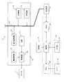
- FIG. 1 is a block diagram schematically showing a marine hybrid propulsion system 10 according to the first embodiment.
- the ship includes a hybrid propulsion system 10, a propeller 11, and a lever 12.
- the hybrid propulsion system 10 includes an electric power and thrust supply system 13, a control unit 14, and a storage unit 15.
- the power and thrust supply system 13 is a system that is connected to the propeller 11 and the inboard power load 21 and supplies power and power generated by the component devices 17, 18, and 19 to the loads 11 and 21.
- the constituent devices are devices that generate rotational power or electric power, and are the main machine 17, the main generator 18, and the motor generator 19.
- One or a plurality of main machines 17, main generators 18 and motor generators 19 are provided in the ship.
- the main engine 17 is a main power source in the hybrid propulsion system 10, and for example, a prime mover such as a diesel engine, a gas engine, or a gas turbine is used.
- the main machine 17 is connected to the speed reducer 20 and is connected to the propeller 11 and the motor generator 19 via the speed reducer 20.
- the speed reducer 20 is a power transmission mechanism, reduces the rotational speed of the power from the main machine 17 to increase the torque, and transmits the power to the propeller 11 and the motor generator 19.
- the main generator 18 is a main power source that supplies electric power to the motor generator 19 and the inboard power load 21 of the ship.
- a generator such as a diesel engine, a gas engine, and a gas turbine with a generator. And connected to the inboard bus 22.
- An inboard power load 21 and a motor generator 19 are connected to the inboard bus 22.
- Examples of the inboard power load 21 include a side thruster (not shown), an auxiliary machine (not shown), a console 23, an electric heater (not shown), and an electric lamp (not shown).
- the inboard power load 21 and the motor generator 19 are connected to a PMS (Power Management System) 24, and output a request for power required when the inboard power load 21 and the motor generator 19 operate to the PMS 24.
- PMS Power Management System
- the PMS 24 is connected to the components 18 and 19 of the control unit 14 and the supply system 13 in addition to the inboard power load 21 and the motor generator 19.
- the PMS 24 obtains the demand power for the hybrid propulsion system 10 based on the required power from the power loads 19 and 21 and outputs the demand power to the control unit 14. Further, the PMS 24 receives the operation mode transition command from the control unit 14 and controls the stop and operation of the component devices 18 and 19 of the supply system 13.
- the motor generator 19 has an electric function and a power generation function, and is connected to the main engine 17 or independently to supply power to the propeller 11, and is connected to the main generator 18 or independently to supply power to the inboard power load. 21.
- the motor generator 19 is connected to the speed reducer 20 and is coupled to the propeller 11 and the main machine 17 via the speed reducer 20.
- the motor generator 19 is connected to the main generator 18 and is connected to the inboard power load 21 via the inboard bus 22.
- the motor generator 19 functions as an electric motor (electric operation)
- it receives electric power from the main generator 18 and generates rotational power.
- the rotational power is transmitted from the motor generator 19 to the propeller 11 via the speed reducer 20, and the propeller 11 rotates to generate thrust.
- the motor generator 19 functions as a generator (power generation operation)
- the motor generator 19 receives the rotational power of the main engine 17 to generate power, and supplies power to the inboard power load 21 via the inboard bus 22.
- a bidirectional power converter 25 is provided between the motor generator 19 and the main generator 18.
- the power conversion device 25 is a power conversion device that changes the AC frequency and voltage from the main generator 18 and the AC frequency and voltage from the motor generator 19. That is, the power conversion device 25 includes a first power conversion unit 25a and a second power conversion unit 25b.
- the first power converter 25a converts the AC power from the main generator 18 into DC power
- the second power converter 25b returns the DC power to AC power
- AC power is output to the motor generator 19.
- the second power converter 25b converts AC power from the motor generator 19 into DC power
- the first power converter 25a returns the DC power to AC power.
- AC power is output to the inboard bus 22 side.
- each power conversion unit 25a, 25b returns from DC power to AC power
- the AC frequency and voltage from the main generator 18 and the motor generator 19 are changed by changing the switching frequency and duty ratio. I have control.
- the storage unit 15 stores the rated output of the component devices 17, 18, and 19 and the correspondence between the outputs of the component devices 17, 18, and 19 and the fuel consumption.
- the fuel consumption amount of the component devices 17, 18, and 19 is the amount of fuel consumed by the component devices 17, 18, and 19 to generate output.
- the storage unit 15 stores a combination of an operation mode before transition that allows automatic transition and an operation mode after transition (permitted transition operation mode combination).
- the allowable transition operation mode combination is set by, for example, the redundancy of the hybrid propulsion system 10 and the supply capability (supplyable thrust and supplyable power).
- the allowable transition operation mode combination is stored in advance in the storage unit 15 manually by an operator such as a crew member and / or automatically by the control unit 14.
- the allowable transition operation mode combination stored in the storage unit 15 may be one or plural.
- the control unit 14 acquires an operation mode with better fuel efficiency than the current operation mode.
- the control unit 14 has better fuel efficiency than the current driving mode among the driving modes corresponding to the driving mode after the transition. Transition to operation mode.
- the fuel efficiency of the hybrid propulsion system 10 is the fuel consumption of the hybrid propulsion system 10 with respect to the supply thrust and power supply of the hybrid propulsion system 10 when operated in each operation mode.
- a known calculation method can be used for the calculation of the fuel consumption.
- the supply thrust and the supply power of the hybrid propulsion system 10 are the sum of the supply thrust and the supply power of the component devices 17, 18 and 19 that are operating.
- the fuel consumption of the hybrid propulsion system 10 is the total amount of fuel consumed by the component devices 17, 18, and 19 to output supply thrust and supply power that satisfy the demand thrust and demand power.
- the fuel consumption amounts of the component devices 17, 18, and 19 are obtained from the relationship between the output per unit device 17, 18, and 19 and the fuel consumption amount in the storage unit 15, and the number of operating units.
- the number of operating components 17, 18, 19 is, for example, the total number of components 17, 18, 19 in the supply system 13, the specified number, or the minimum number that satisfies the demand. In this operation mode, this is determined depending on whether the entire number or the designated number is always operated, or only the necessary number is operated by starting and stopping according to demand.
- the propeller 11 is a propulsion device that gives thrust to the ship, and one or more propellers 11 are provided in the ship.
- the propeller 11 is connected to the speed reducer 20.
- the propeller 11 receives the rotational power output from the main engine 17 and / or the motor generator 19 that is electrically operated via the speed reducer 20, and converts the rotational power into thrust.
- the thrust of the propeller 11 is controlled by the rotation speed of the propeller 11 adjusted by the speed reducer 20 and the pitch angle (blade angle) of the propeller 11 adjusted by a pitch angle adjusting mechanism (not shown).
- the lever 12 is a control stick for the operator to input the demand thrust of the ship.
- the throttle lever 12 is used and is provided on the console 23.
- the lever 12 is connected to a PCS (Propulsion Control System) 26 and outputs an operation amount of the lever 12 by the operator to the PCS 26.
- the PCS 26 is further connected to the control unit 14, the control device (not shown) of the main machine 17, and the pitch angle adjusting mechanism.
- the PCS 26 determines the demand thrust, the rotational speed of the main engine 17, and the pitch angle of the propeller 11 based on the operation amount of the lever 12.
- the PCS 26 outputs the demand thrust to the control unit 14, outputs the rotation speed of the main machine 17 to the control device of the main machine 17, and outputs the pitch angle of the propeller 11 to the pitch angle adjustment mechanism.
- the thrust of the propeller 11 is controlled by the rotation speed and pitch angle of the propeller 11.
- control part 14, PMS24, and PCS26 may be comprised by one control apparatus, and may each be comprised by three separate control apparatuses.
- these 14, 24, and 26 are configured by a single control device, the functions of the control unit 14, the PMS 24, and the PCS 26 are realized by a program stored in the control device.
- FIGS. 2A to 2E are block diagrams showing operation modes of the marine hybrid propulsion system 10.
- the machine propulsion mode of FIG. 2A is an operation mode in which the motor generator 19 stops and the main machine 17 and the main generator 18 operate independently.
- 2B to 2E are operation modes in which the motor generator 19 operates in conjunction with the main engine 17 or the main generator 18.
- the main machine 17 In the machine propulsion mode of FIG. 2A, the main machine 17 operates, the main generator 18 operates, and the motor generator 19 stops. In this machine propulsion mode, the main engine 17 supplies rotational power to the propeller 11 via the speed reducer 20.
- the main generator 18 supplies power to the inboard power load 21 (FIG. 1) via the inboard bus 22. As described above, the thrust of the propeller 11 is given by the rotational power of the main machine 17, and the power of the inboard power load 21 is given from the main generator 18.
- the main machine 17 is stopped, the main generator 18 is operated, and the motor generator 19 is electrically operated.
- the main generator 18 supplies power to the ship power load 21 via the ship bus 22 and supplies power to the motor generator 19 via the power converter 25.
- the motor generator 19 receives the electric power from the main generator 18 to generate rotational power, and supplies the rotational power to the propeller 11 via the speed reducer 20. For this reason, the thrust of the propeller 11 is given by the rotational power of the motor generator 19.
- the output of the motor generator 19 is designed to be smaller than the output of the main engine 17, the supplyable thrust in the electric propulsion mode is smaller than that in the mechanical propulsion mode of FIG. 2A.
- the main engine 17 operates, the main generator 18 operates, and the motor generator 19 operates electrically.
- the main generator 18 supplies electric power to the inboard power load 21 through the inboard bus 22 and also supplies electric power to the motor generator 19.
- the motor generator 19 and the main machine 17 supply the rotational power to the propeller 11 via the speed reducer 20.
- the thrust that can be supplied in the propulsion boost mode is larger than that in the mechanical propulsion mode of FIG. 2A.
- the main machine 17 in the parallel mode, the main machine 17 operates, the main generator 18 operates, and the motor generator 19 generates power.
- the main generator 18 supplies power to the inboard power load 21 via the inboard bus 22.
- the main machine 17 supplies rotational power to the propeller 11 and the motor generator 19.
- the motor generator 19 generates power by receiving rotational power from the main engine 17 and supplies electric power to the inboard power load 21 through the inboard bus 22.
- the power that can be supplied in the parallel mode is larger than that in the mechanical propulsion mode of FIG. 2A.
- the main engine 17 operates, the main generator 18 stops, and the motor generator 19 generates power.
- the main engine 17 supplies rotational power to the propeller 11 and the motor generator 19.
- the motor generator 19 generates power by receiving rotational power from the main engine 17 and supplies electric power to the inboard power load 21 through the inboard bus 22.
- electric power is supplied only from the motor generator 19.
- the output of the motor generator 19 is designed to be smaller than the output of the main generator 18, the power that can be supplied in the axial mode is smaller than that in the mechanical propulsion mode in FIG. 2A.
- the operation mode is distinguished depending on the number and output of the component devices 17, 18, 19 that operate. It is good or not distinguished.
- the hybrid propulsion system 10 of FIG. 1 includes two main generators 18. In this case, the electric propulsion mode in which one main generator 18 and one motor generator 19 are operating, and the electric propulsion in which two main generators 18 and one motor generator 19 are operating.
- the mode may be determined as a different operation mode, or may be determined as the same operation mode.
- the operation mode may be distinguished according to the redundancy. For example, even if the number of component devices 17, 18, and 19 that operate is different, the same operation mode may be determined as long as the redundancy is equal. In this case, the supply capability is obtained from the total number of operating devices 17, 18, and 19 and the rated output in the operation mode. In addition, the fuel efficiency is obtained from the minimum number of operating components 17, 18, and 19 that can be supplied and the rated output of the components 17, 18, and 19. On the other hand, if the number of operating components 17, 18, and 19 is different and the redundancy is different, it may be determined that the operation mode is different. In this case, both the supply capability and the fuel consumption are obtained from the total number of operating devices 17, 18, and 19 and the rated output in the operation mode.
- FIG. 3 is a graph showing the allowable transition operation mode combinations.
- the graph of FIG. 3 is divided into 10 blocks by a central vertical line, a central horizontal line, an upper oblique line, and a lower oblique line.
- the block on the right side of the center vertical line is an operation mode in which the main machine 17 is operating
- the block on the left side of the center vertical line is an operation mode in which the main machine 17 is stopped.
- the block above the central horizontal line is an operation mode in which the main generator 18 is operating
- the block below the central horizontal line is an operation mode in which the main generator 18 is stopped.
- the upper left block from the upper oblique line is an operation mode in which the motor generator 19 is electrically operated
- the block between the upper oblique line and the lower oblique line is an operation mode in which the motor generator 19 is stopped.
- the lower right block is an operation mode in which the motor generator 19 is generating power.
- an operation mode (berthing mode) while the ship is anchored is also shown.
- this berthing mode the main machine 17 stops, the main generator 18 operates, and the motor generator 19 stops. For this reason, rotational power is not supplied to the propeller 11, but electric power is supplied from the motor generator 19 to the inboard power load 21 through the inboard bus 22.
- the arrows between the operation modes in FIG. 3 represent the transition of the operation modes.
- the solid arrow indicates that it is allowed to automatically transition from the operation mode before the transition at the base end of the arrow to the operation mode after the transition at the tip of the arrow.
- a combination of operation modes in which automatic transition is permitted (allowable transition operation mode combination) is stored in the storage unit 15.
- the dotted arrow indicates that it is not permitted to automatically change from the operation mode before the transition at the base end of the arrow to the operation mode after the transition at the tip of the arrow. In this case, it is possible to manually change from the operation mode before the transition to the operation mode after the transition.
- combinations of four operation modes are stored in the storage unit 15 as allowable transition operation mode combinations.
- the four allowable transition operation mode combinations are transitions from the electric propulsion mode to the propulsion boost mode, from the axial mode to the parallel mode, from the propulsion boost mode to the parallel mode, and from the parallel mode to the propulsion boost mode.
- the transition between the five operation modes excluding the anchoring mode indicated by the arrows is set so as to switch the stop and operation of one type of component devices 17, 18, and 19.
- the transition from the electric propulsion mode to the propulsion boost mode is performed by switching the main engine 17 from the stop to the operation.
- the transition from the propulsion boost mode to the parallel mode is performed by switching the motor generator 19 from the motor operation to the power generation operation.
- the operation mode transition may be set so that the stop and operation of two or more types of component devices 17, 18, and 19 are switched.
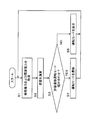
- FIG. 4 is a flowchart illustrating an example of the control of the marine hybrid propulsion system 10.
- the operator determines the work content of the ship and operates the lever 12 and the inboard power load 21 according to the work content.
- the operation amount of the lever 12 is input to the PCS 26, and the required power of the inboard power load 21 is input to the PMS 24.
- the PMS 24 totals the required power from the inboard power load 21 to obtain the demand power for the hybrid propulsion system 10 and outputs the demand power to the control unit 14.
- the PCS 26 obtains a demand thrust based on the operation amount of the lever 12 and outputs the demand thrust to the control unit 14.
- the control part 14 acquires a demand thrust from PCS26, and acquires a demand power from PMS24 (step S1).
- the control unit 14 obtains an operation mode with better fuel efficiency than the current operation mode, among operation modes having supply capability that satisfies the demand. Then, in the allowable transition operation mode combination stored in the storage unit 15, the control unit 14 determines whether the operation mode with good fuel consumption matches the operation mode after the transition, and the current operation mode matches the operation mode before the transition. It is determined whether or not (step S3). If the combination of the current operation mode and the operation mode with good fuel efficiency does not correspond to the allowable transition operation mode combination (step S3: NO), the process returns to step S1, and the processes of S1 to S3 are repeated. In this case, the operation of the marine hybrid propulsion system 10 in the current operation mode with good fuel efficiency is maintained.
- step S4 if the transition from the current operation mode to the operation mode with good fuel consumption corresponds to the allowable transition operation mode combination (step S3: YES), the control unit 14 executes the transition of the operation mode (step S4).
- the operation mode transitions to the operation mode with the highest fuel consumption among the operation modes with good fuel consumption.
- the control unit 14 outputs to the PCS 26 and the PMS 24 a command for transition to an operation mode with good fuel efficiency.
- the PCS 26 outputs the rotation speed of the main machine 17 based on the operation amount of the lever 12 to the control device of the main machine 17 and outputs the pitch angle of the propeller 11 to the pitch angle adjusting mechanism.
- the supply thrust of the propeller 11 is controlled according to the operation mode after transition.
- the PMS 24 switches between the operation and stop of the main engine 17 and the main generator 18 and the electric operation, power generation operation and stop of the motor generator 19 according to the operation mode after the transition. Thereby, supply electric power is controlled according to the operation mode after transition.
- the operation mode transition is executed by the control unit 14.
- the operation mode is automatically changed, so that the operator's trouble can be saved and the operation mode can be switched quickly.
- an operation mode in which fuel efficiency is better than the current operation mode is selected from among operation modes in which the supply capability is greater than the demand. Therefore, it is possible to quickly shift to an appropriate operation mode with improved fuel efficiency while meeting demand.
- the operation mode is changed to an appropriate operation mode. For example, when the operator decides the work content of the day by meeting, the operator determines the redundancy according to the work content and the state of the outside world. At this time, the operator can store the allowable transition operation mode combination in the storage unit 15 in consideration of the redundancy. Therefore, it is possible to avoid the transition to the operation mode in which the redundancy is lowered against the operator's intention. As a result, it is possible to quickly transition to an appropriate operation mode that ensures safety.
- the driving mode with better fuel efficiency than the current driving mode may be the driving mode with the highest fuel efficiency.
- the control unit 14 obtains an operation mode with the best fuel consumption among the operation modes in which the supplyable thrust is larger than the demand thrust and the supplyable power is larger than the demand power. If the current driving mode and the driving mode with the best fuel consumption match the driving mode before transition and the driving mode after transition of the allowable transition driving mode combination (step S3: YES), the control unit 14 is in the driving mode. A transition is executed (step S4).
- the operation mode transition is automatically executed by the control unit 14. Therefore, it is possible to quickly shift to an appropriate operation mode stored in advance according to the operator's intention.
- the inboard bus 22 is divided into a plurality of sections, and the plurality of sections are connected by a circuit breaker 27.
- the operation mode includes the operation or stop of the main machine 17, the operation or stop of the main generator 18, and the motor operation, power generation operation or stop of the motor generator 19, and the circuit breaker 27 being disconnected or connected. It is determined by the combination.
- FIG. 5 is a block diagram showing the marine hybrid propulsion system 10 according to the second embodiment.
- the inboard bus 22 is divided into two sections, and two supply systems 13 are provided in each section.
- a circuit breaker 27 is provided between the two sections of the inboard bus 22.
- the circuit breaker 27 is a device for interrupting and connecting the inboard bus 22, and for example, a bus tie breaker (BTB) is used.
- One or more circuit breakers 27 are connected to the control unit 14 and provided on the inboard bus 22.
- the inboard bus 22 is interrupted by the circuit breaker 27, there is no exchange of power between the supply systems 13, and the supply systems 13 are operated individually. For this reason, when the motor generator 19 operates electrically, thrust is generated by receiving power from the main generator 18 in the same supply system 13 as in the electric propulsion mode and the propulsion boost mode.
- the inboard bus 22 when the inboard bus 22 is connected by the circuit breaker 27, power can be exchanged between the supply systems 13. For this reason, electric power can be supplied from one supply system 13 to the other supply system 13 via the inboard bus 22.
- the supply system 13 can be operated in the external power supply mode in which the motor generator 19 receives electric power from the other supply system 13 and generates thrust.
- the supply system 13 operated in the axial mode and the supply system 13 operated in the external power supply mode are connected via the circuit breaker 27.
- the supply system 13 connected to the left side of the circuit breaker 27 in the drawing is operated in the axial mode.
- the motor generator 19 generates power and supplies power to the inboard power load 21 via the inboard bus 22.
- the supply system 13 connected to the right side of the circuit breaker 27 in the drawing is operated in the external power supply mode.
- the main machine 17 and the main generator 18 are stopped, and the motor generator 19 is electrically operated.
- the motor generator 19 receives electric power from the supply system 13 in the axial mode and generates rotational power, and rotates the propeller 11 to obtain thrust.
- the fuel efficiency of the hybrid propulsion system 10 is obtained by the fuel consumption of the hybrid propulsion system 10 with respect to the supply thrust and power supply of the hybrid propulsion system 10.
- the fuel consumption of the hybrid propulsion system 10 is This is the total fuel consumption of each component device 17, 18, 19.
- the supply thrust and the supply power of the hybrid propulsion system 10 are the sum of the supply thrust and the supply power of the component devices 17, 18, and 19.
- the supply system 13 can be operated in the external power supply mode by connecting the inboard bus 22 with the circuit breaker 27. For this reason, the variation of an operation mode increases and it can be changed to the appropriate operation mode which improved safety. Moreover, the choice of the driving mode with good fuel consumption increases, and it can be changed to the appropriate driving mode with better fuel consumption.
- FIG. 6 is a block diagram showing a marine hybrid propulsion system 10 according to the third embodiment. As shown in FIG. 6, the display unit 28 is connected to the control unit 14 and is provided, for example, on the console 23.
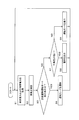
- FIG. 7 is a flowchart showing an example of control of the marine hybrid propulsion system 10 according to the third embodiment. Also in the flow shown in FIG. 7, the processes of steps S1 to S4 shown in FIG. 4 are executed. However, in the flow shown in FIG. 7, after the process of step S4, a process (step S5) for displaying an operation mode with good fuel efficiency is executed.
- step S3 YES
- the control unit 14 determines the operation mode with good fuel efficiency from the current operation mode.
- the operation mode is changed to (Step S4).
- the control unit 14 causes the display unit 28 to display the driving mode with good fuel efficiency to be changed (step S5).
- the operation mode transition is executed and the operation mode with good fuel consumption is displayed on the display unit 28. Is displayed. Therefore, it is possible to inform the operator of the operation mode executed after the transition.
- the hybrid propulsion system 10 according to the third embodiment further includes the circuit breaker 27 in FIG. 5, thereby providing the same effects as those of the second embodiment.
- the marine hybrid propulsion system 10 according to the fourth embodiment is configured to display an operation mode with good fuel consumption on the console 23.
- the display unit 28 of the console 23 is connected to the control unit 14.
- FIG. 8 is a flowchart showing an example of control of the marine hybrid propulsion system 10 according to the fourth embodiment. Also in the flow shown in FIG. 8, the processes of steps S1 to S4 shown in FIG. 4 are executed. However, in the flow shown in FIG. 8, after the process of step S3, the process (step S6) of displaying the driving mode with good fuel efficiency is executed.
- step S3 if the combination of the current operation mode and the operation mode with good fuel consumption does not correspond to the allowable transition operation mode combination (step S3: NO), the operation mode with good fuel consumption is displayed on the display unit 28 (step S3). S6).
- the transition from the current operation mode to the operation mode with good fuel efficiency is not automatically performed, but the operator can be notified of the operation mode with good fuel efficiency. For this reason, even if it is not the driving mode in which automatic transition is permitted, the operator can manually perform the transition to the driving mode with good fuel efficiency. Therefore, it is possible to realize an appropriate operation mode transition in accordance with the operator's intention.
- step S ⁇ b> 5 processing (step S ⁇ b> 5) for displaying an operation mode with good fuel efficiency may be executed.
- step S ⁇ b> 5 processing (step S ⁇ b> 5) for displaying an operation mode with good fuel efficiency may be executed.
- the hybrid propulsion system 10 according to the fourth embodiment further includes the circuit breaker 27 of FIG. 5, thereby providing the same effects as those of the second embodiment.
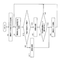
- FIG. 9 is a flowchart showing an example of control of the marine hybrid propulsion system 10 according to the fifth embodiment. Also in the flow shown in FIG. 9, the processes of steps S1 to S4 shown in FIG. 4 are executed. However, in the flow shown in FIG. 9, it is determined whether or not the redundancy of the fuel-efficient driving mode is lower than the current driving mode after the process of step S3 (step S7).
- step S3: NO the control unit 14 determines the redundancy of the current operation mode, The redundancy of the driving mode with good fuel efficiency is obtained. If the redundancy of the operation mode with good fuel consumption is larger than the current operation mode (step S7: NO), the redundancy does not decrease due to the transition from the current operation mode to the operation mode with good fuel consumption. For this reason, the control part 14 displays the driving mode with good fuel consumption on the display part 28 (step S6). Thereby, since the operator can be notified of the driving mode with good fuel consumption, the operator can manually perform the transition to the driving mode with good fuel consumption. Therefore, it is possible to realize an appropriate operation mode transition in accordance with the operator's intention.
- step S7 YES
- the redundancy of the operation mode with good fuel consumption is lower than the current operation mode (step S7: YES)
- the control part 14 displays the warning which shows that a redundancy reduces with the driving mode with favorable fuel consumption on the display part 28 (step S8).
- an operation mode with good fuel efficiency may not be displayed.
- processing (step S5) for displaying an operation mode with good fuel efficiency may be executed after the processing in step S4.
- step S5 for displaying an operation mode with good fuel efficiency
- the hybrid propulsion system 10 according to the fifth embodiment further includes the circuit breaker 27 of FIG. 5, thereby providing the same effects as those of the second embodiment.
- any two operation modes are operated such that the thrust and power supply range of one operation mode is smaller than the thrust and power supply range of the other operation mode. It is a combination of modes.
- the control unit 14 stores the combination of the operation modes in the storage unit 15 as an allowable transition operation mode combination in which one operation mode is the operation mode before transition and the other operation mode is the operation mode after transition. To do.
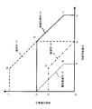
- FIG. 10 is a graph showing the thrust that can be supplied and the power that can be supplied in the operation mode.
- the vertical axis represents the power that can be supplied, and the horizontal axis represents the thrust that can be supplied.
- OA indicates the rated thrust of the main machine 17
- OD indicates the rated power of the main generator 18.
- OF indicates the rated thrust of the motor generator 19 that operates electrically
- OC indicates the rated power of the motor generator 19 that operates.
- the supplyable capacity includes a supplyable thrust and a supplyable power represented by a thrust and power supplyable range.
- the range of OABC shows the range in which thrust and power can be supplied in the axial mode.
- the main engine 17 supplies the thrust of the propeller 11 (rotational power of the propeller 11) and the driving power of the motor generator 19 that is generating power, and the motor generator 19 uses the driving power from the main engine 17 as electric power. Converted to supply.
- the maximum supply thrust in the axial mode is the rated thrust (OA) of the main engine 17, and the maximum supply power is the rated power (OC) of the motor generator 19.
- the range of ODEF indicates the thrust and electric power supply possible range in the electric propulsion mode.
- the main generator 18 supplies electric power and electric power of the motor generator 19 that is electrically operated, and the motor generator 19 converts the electric power from the main generator 18 into thrust of the propeller 11 and supplies it. ing. Therefore, the maximum supply thrust in the electric propulsion mode is the rated thrust (OF) of the motor generator 19, and the maximum supply power is the rated power (OD) of the main generator 18.
- the range of OAGHI indicates the parallel mode thrust and power supply possible range.
- the main machine 17 supplies the thrust of the propeller 11 and the driving power of the motor generator 19 that is generating power, and the motor generator 19 converts the driving power from the main machine 17 into electric power and supplies it.
- Machine 18 is supplying power. Therefore, the maximum supply thrust in the parallel mode is the rated thrust (OA) of the main engine 17, and the maximum supply power is the total power of the rated power (OC) of the motor generator 19 and the rated power (OD) of the main generator 18. (OI).
- the range of ODGJK shows the thrust and power supply possible range in the propulsion boost mode.
- the main generator 18 supplies electric power and electric power of the motor generator 19 that is electrically operated, and the motor generator 19 converts electric power from the main generator 18 into rotational power of the propeller 11.
- the main engine 17 supplies the thrust of the propeller 11. Therefore, the maximum supply thrust in the propulsion boost mode is the total thrust (OK) of the rated thrust (OF) of the motor generator 19 and the rated thrust (OA) of the main engine 17, and the maximum supply power is the rating of the main generator 18.
- Electric power (OD) Electric power
- the supply capability (thrust and power supply range) of the operation mode of the hybrid propulsion system 10 in the case where each of the main engine 17, the main generator 18, and the motor generator 19 is included is shown. ing. Therefore, in the case where the hybrid propulsion system 10 includes a plurality of component devices 17, 18, and 19, the capability of supply of the operation mode is determined by the number of component devices 17, 18, and 19 that are operating and their rated outputs. Ask.
- FIG. 11 is a flowchart illustrating an example of control of the marine hybrid propulsion system 10 according to the sixth embodiment. Also in the flow shown in FIG. 11, the processes of steps S1 to S4 shown in FIG. 4 are executed. However, in the flow shown in FIG. 11, before the process of step S ⁇ b> 1, the control unit 14 changes each combination of operation modes in which the supply capability in one operation mode is smaller than the supply capability in the other operation mode. Are stored in the storage unit 15 (step S9). Moreover, in the flow shown in FIG. 11, it is determined after the process of step S1 whether the supply capability is larger than the demand (step S10). The storage of the allowable transition operation mode combination may be performed as appropriate.
- the control unit 14 obtains the thrust and power supply possible range in each operation mode. And the control part 14 memorize
- the supplyable range in the parallel mode is larger than the axial mode.
- a combination of operation modes in which the axis departure mode is the operation mode before the transition and the parallel mode is the operation mode after the transition is automatically stored as the allowable transition operation mode combination.
- the axis departure mode is the operation mode before the transition
- the parallel mode is the operation mode after the transition is automatically stored as the allowable transition operation mode combination.
- the supplyable range of the propulsion boost mode is larger than the electric propulsion mode. For this reason, as shown in FIG. 3, a combination of operation modes in which the electric propulsion mode is the operation mode before transition and the propulsion boost mode is the operation mode after transition is automatically stored as the allowable transition operation mode combination. .
- the control unit 14 acquires the demand thrust and demand power (step S1). Further, the control unit 14 determines whether or not the supply capability in the current operation mode is greater than the demand (step S10). Here, if the suppliable capacity is greater than the demand (step S10: YES), the current operation mode can cover the demand thrust and power demand, so the control unit 14 calculates the fuel consumption (step S2). And the control part 14 calculates
- the control unit 14 determines that the combination of operation modes that transition from the electric propulsion mode to the propulsion boost mode is the allowable transition operation mode. Since it corresponds to the combination, the mode is automatically shifted to the propulsion boost mode.
- the combination of the operation modes that transition from the axial mode to the parallel mode corresponds to the allowable transition mode combination. Automatically transition to.
- step S10 NO
- the control unit 14 selects, from the allowable transition operation mode combinations, the transition to the operation mode having a supply capability larger than the demand among the allowable transition operation mode combinations in which automatic transition is permitted from the current operation mode. (Step S11). And the control part 14 performs the transition of an operation mode (step S4).
- the transition from the current operation mode to the operation mode having an ability that can be supplied larger than the demand is selected from the storage unit 15 among the allowable transition operation mode combinations in which automatic transition is permitted, and the transition is executed. Therefore, even when the supply capability of the hybrid propulsion system 10 is insufficient, it is possible to quickly shift to an appropriate operation mode that can cover the demand.
- step S11 in FIG. 11 the transition of the driving mode is selected without considering the fuel consumption. However, when there are a plurality of options, the transition of the driving mode may be selected in consideration of the fuel consumption. In this case, if the supply capability in the current operation mode is smaller than the demand (step S10: NO), the control unit 14 calculates the fuel consumption (step S2). Then, the control unit 14 stores a transition to an operation mode that has a supply capability greater than the demand and has good fuel efficiency in the combination of operation-permitted transition operation modes in which automatic transition is permitted from the current operation mode. 15 is selected (step S11). And the control part 14 performs the transition of an operation mode (step S4).
- the process of step S9 may not be executed before the process of step S1.
- the storage unit 15 stores a combination of operation modes in which the supply range of the operation mode after the transition is larger than the operation mode before the transition manually by the operator.
- the control unit 14 automatically transitions to the propulsion boost mode or the parallel mode when the driving mode with the best fuel consumption is the propulsion boost mode or the parallel mode.
- the hybrid propulsion system 10 according to the sixth embodiment further includes the circuit breaker 27 of FIG. 5, thereby providing the same effects as those of the second embodiment.
- the hybrid propulsion system 10 according to the sixth embodiment further includes the display unit 28 in FIG. 6, and in the flow shown in FIG. 11, the process in step S5 in FIG. 7, the process in step S6 in FIG. 8, or the step in FIG. The processing of S6 to S8 may be executed. As a result, the same effects as those of the third to fifth embodiments are obtained.
- any two operation modes are combinations of operation modes in which the redundancy set in one operation mode is greater than the redundancy set in the other operation mode. is there.
- the control unit 14 stores the combination of the operation modes in the storage unit 15 as an allowable transition operation mode combination in which one operation mode is the operation mode before transition and the other operation mode is the operation mode after transition. It is configured not to.
- the control unit 14 sets the redundancy for each of the operation mode before the transition and each operation mode after the transition.
- the redundancy of the operation mode is such that when the supply capability of the hybrid propulsion system 10 is reduced due to a failure of any of the component devices 17, 18 and 19, the supply capability can supply the demand.
- the redundancy of the operation mode is represented by, for example, a level according to a predetermined rule or a parallel operation state of the operation mode.
- the level according to the predetermined rule includes, for example, a level according to a dynamic positioning class defined by the International Maritime Organization and a level according to a certain rule based on the dynamic positioning class.
- Certain rules in accordance with the dynamic positioning class established by the International Maritime Organization include, for example, DNV GL (formerly Det Norske Veritas and German Lloyd Classification Society (Germanischer Lloyd)), and , Rules on dynamic positioning established by classification societies such as American Bureau of Shipping (American Bureau of Shipping).
- DNV GL originally Det Norske Veritas and German Lloyd Classification Society (Germanischer Lloyd)
- Rules on dynamic positioning established by classification societies such as American Bureau of Shipping (American Bureau of Shipping).
- the correspondence relationship between the operation mode and the redundancy is stored in the storage unit 15 in advance. Therefore, based on this correspondence, the redundancy of the operation mode before the transition and the redund
- the control unit 14 obtains the redundancy of the operation mode from the number of operating component devices 17, 18, 19. That is, the greater the number of component devices 17, 18, and 19 that operate, the greater the number of component devices 17, 18, and 19 that continue to operate even if any component device 17, 18, or 19 fails. For this reason, a large thrust and electric power can be supplied, and the redundancy of the operation mode is high. Therefore, the redundancy of the operation mode can be regarded as the number of component devices 17, 18, and 19 that operate in each operation mode.
- various components 17, 18, 19 are connected to the propeller 11 and the inboard bus 22 one by one.
- the parallel mode two generators of the main generator 18 and the motor generator 19 that performs the power generation operation operate.
- the axial mode one generator of the motor generator 19 that performs the power generation operation operates. Accordingly, since the number of generators operating in the parallel mode is larger than that in the axial mode, the power redundancy in the parallel mode is higher than that in the axial mode.
- the propulsion boost mode two devices, the main machine 17 and the motor generator 19 that is electrically operated, generate thrust.
- the electric propulsion mode one device of the motor generator 19 that operates electrically generates thrust. Therefore, in the propulsion boost mode, the number of devices that generate thrust is larger than that in the electric propulsion mode, and thus the thrust redundancy in the propulsion boost mode is higher than in the electric propulsion mode.
- the redundancy of the operation mode considers the circuit breaker 27 and the circuit breaker 27 in addition to the number of operating devices 17, 18, 19. .
- the failure of the inboard bus 22 affects both supply systems 13. Effect. Therefore, the redundancy at the time of connection of the circuit breaker 27 is lower than the redundancy at the time of interruption.
- control unit 14 compares the obtained redundancy set in the operation mode before transition with the redundancy set in the operation mode after transition. As a result, if the redundancy of the operation mode after the transition is lower than that before the transition, the control unit 14 does not store the combination of the operation mode before the transition and the operation mode after the transition in the storage unit 15 as the allowable transition operation mode combination.
- the redundancy of the operation mode is determined by each of thrust and electric power. For this reason, the redundancy of the thrust of the operation mode after the transition is lower than the redundancy of the thrust of the operation mode before the transition, or the redundancy of the power of the operation mode after the transition is the redundancy of the power of the operation mode before the transition. When it is lower than the degree, it is determined that the redundancy of the operation mode after the transition is lower than that before the transition.
- the redundancy of one operation mode is a combination of operation modes greater than the redundancy of the other operation mode
- one operation mode is set as the operation mode before the transition
- the other operation mode is set as the operation mode.
- the combination of the operation modes to be the operation mode after the transition is not stored as the allowable transition operation mode combination. As a result, the transition of the operation mode in which the redundancy is lowered is prevented from being automatically performed, and the switching to the safe operation mode can be performed.
- the control unit 14 since the redundancy of the operation mode is obtained by the control unit 14, it is possible to save the operator from having to obtain the redundancy of the operation mode, and the workability is excellent.
- the hybrid propulsion system 10 according to the seventh embodiment may further include the circuit breaker 27 of FIG. Thereby, the same effects as those of the second embodiment are obtained.
- the hybrid propulsion system 10 according to the seventh embodiment further includes the display unit 28 in FIG. 6, and in the flow shown in FIG. 11, the process in step S5 in FIG. 7, the process in step S6 in FIG. 8, or the step in FIG. The processing of S6 to S8 may be executed. As a result, the same effects as those of the third to fifth embodiments are obtained.
- FIG. 12 is a block diagram showing a marine hybrid propulsion system 10 according to the eighth embodiment.
- the input unit 29 is connected to the control unit 14, and is provided on the console 23 using, for example, a keyboard or a touch pad.
- the control unit 14 stores the allowable transition operation mode combination in the storage unit 15 or deletes the allowable transition operation mode combination from the storage unit 15 according to the operation input by the input unit 29.
- Embodiment 7 storage of combinations of operation modes in which the redundancy of the operation mode after the transition is lower than the operation mode before the transition is not allowed.
- the operator uses the input unit 29 to input a combination of operation modes in which the redundancy of the operation mode after the transition is lower than the operation mode before the transition.
- control part 14 memorize
- the hybrid propulsion system 10 is required to maintain the ship's position holding ability even if an equipment failure occurs. Redundancy is high.
- the operator uses the input unit 29 to determine the redundancy of the operation mode in which the redundancy of the operation mode after the transition is required from the allowable transition operation mode combination already stored in the storage unit 15. Delete the lower allowable transition mode combination.
- the control unit 14 deletes the allowable transition operation mode combination lower than the redundancy of the operation mode in which the redundancy of the operation mode after the transition is requested from the storage unit 15 in response to the request from the input unit 29.
- the allowable transition operation mode combination can be stored in the storage unit 15 or deleted from the storage unit 15 according to the operation input by the input unit 29. Therefore, it is possible to set the operation mode appropriately according to conditions such as the degree of redundancy that changes every day depending on the work content of the ship and the state of the outside world, and make automatic transition.
- the same effects as those of the first, sixth and seventh embodiments are obtained by executing the processing of each step according to the first, sixth and seventh embodiments.
- the hybrid propulsion system 10 according to the eighth embodiment may further include the circuit breaker 27 of FIG. Thereby, the same effects as those of the second embodiment are obtained.
- the hybrid propulsion system 10 according to the eighth embodiment may further include the display unit 28 of FIG. 6 and execute the processes of the steps of FIGS. 7 to 9. As a result, the same effects as those of the third to fifth embodiments are obtained.
- the storage unit 15 uses a combination of the pre-failure operation mode, the failure state of the device in the pre-failure operation mode, and the post-failure operation mode as a transition operation mode during failure. Further remember as a combination.
- the control unit 14 is configured to automatically transition to the post-failure operation mode of the failure transition operation mode combination corresponding to the current operation mode that is the pre-failure operation mode and the failure state of the device when the device fails. Has been.
- This failure time transition operation mode combination may be manually stored by the operator using the input unit 29 of FIG. 12, or may already be stored by a method other than the input unit 29.
- the storage unit 15 stores the transition operation mode combination at the time of failure in addition to the allowable transition operation mode combination.
- This failure transition operation mode combination is a combination of the failure state of the component devices 17, 18, and 19, the operation mode before the failure, and the operation mode after the failure.
- Examples of the failure state of the component devices 17, 18, and 19 include the type, number, and output of the component devices 17, 18, and 19 that have failed.
- the types of the component devices 17, 18, and 19 that are out of order include the main machine 17, the main generator 18, the motor generator 19, only the motor function of the motor generator 19, and only the power generation function of the motor generator 19.
- the operation mode after transition in which automatic transition is allowed at the time of failure is set according to the failure state of the component devices 17, 18, and 19 and the operation mode at the time of failure.
- the operation mode after the transition is set to the operation mode in which the motor generator 19 is stopped with respect to the operation mode before the transition in which the motor generator 19 is operated.
- the transition from the boost propulsion mode to the machine propulsion mode shown in FIG. 3 and the transition from the parallel mode to the machine propulsion mode can be mentioned.
- FIG. 13 is a flowchart showing an example of control of the marine hybrid propulsion system 10 according to the ninth embodiment. Also in the flow shown in FIG. 13, the processes of steps S1 to S4 according to the first embodiment shown in FIG. 4 are executed. However, in the flow shown in FIG. 13, it is determined whether or not there is a failure after the process of step S1 (step S12). (Step S13).
- control unit 14 acquires the demand thrust and the power demand (step S1), and monitors the failure of the component devices 17, 18, and 19 (step S12). If the component devices 17, 18, and 19 are not malfunctioning (step S12: NO), the control unit 14 calculates fuel consumption (step S2) and executes a transition from the current operation mode to the operation mode with good fuel consumption (step S2). Step S3: YES, step S4).
- step S12 if a failure occurs in the component devices 17, 18, and 19 (step S12: YES), the control unit 14 matches the current failure content with the failure state, and the current operation mode becomes the operation mode before the transition.
- a matching transition operation mode combination at the time of failure is selected (step S13). For example, when the current operation mode is the propulsion boost mode and the motor generator 19 fails, as shown in FIG. 3, the transition transition mode combination at the time of transition from the propulsion boost mode to the machine propulsion mode is selected. To do. And the control part 14 performs the transition to the operation mode after the transition of the selected transition operation mode combination at the time of failure from the present operation mode (step S4).
- the storage unit 15 stores a combination of operation modes (automatic transition operation mode combination) that allows automatic transition when a failure occurs. Thereby, since a transition is automatically made to the operation mode corresponding to the failure content at the time of failure, a quick transition to an appropriate operation mode is realized.
- step S13 in FIG. 13 the transition of the driving mode is selected without considering the fuel consumption. However, when there are a plurality of options, the transition of the driving mode may be selected in consideration of the fuel consumption.
- the control unit 14 calculates fuel consumption (step S2). And the control part 14 selects the transition operation mode combination at the time of a failure in which the present failure content corresponds to a failure state, and the present operation mode corresponds to the operation mode before a transition (step S13). And the control part 14 performs the transition to the operation mode after the transition of the selected transition operation mode combination at the time of failure from the present operation mode (step S4).
- the hybrid propulsion system 10 according to the ninth embodiment may further include the circuit breaker 27 of FIG. Thereby, the same effects as those of the second embodiment are obtained.
- the hybrid propulsion system 10 according to the ninth embodiment may further include the display unit 28 in FIG. 6, and may execute the processing of each step in FIGS. As a result, the same effects as those of the third to fifth embodiments are obtained.
- the hybrid propulsion system 10 according to the ninth embodiment may further include the input unit 29 of FIG. As a result, the same effects as those of the eighth embodiment are obtained.
- the hybrid propulsion system for a ship according to the present invention is useful as a hybrid propulsion system for a ship that can quickly shift to an appropriate operation mode.
Landscapes
- Chemical & Material Sciences (AREA)
- Engineering & Computer Science (AREA)
- Combustion & Propulsion (AREA)
- Mechanical Engineering (AREA)
- Ocean & Marine Engineering (AREA)
- Electric Propulsion And Braking For Vehicles (AREA)
- Control Of Eletrric Generators (AREA)
Abstract
船舶のハイブリッド推進システム(10)は、主機(17)、主発電機(18)および電動発電機(19)を備え、自動遷移が許容される遷移前の運転モードと遷移後の運転モードとの組み合わせである許容遷移運転モード組み合わせを記憶する記憶部(15)と、各運転モードについて、現在の推力需要および電力需要が各運転モードについて規定された供給可能推力の変化に対する供給可能電力の変化特性により定まる推力及び電力の供給可能範囲内にある場合にその燃費を演算して、現在の運転モードより燃費の良い運転モードを取得し、現在の運転モードと燃費の良い運転モードとの組み合わせが遷移許容運転モード組み合わせに該当する場合、遷移後の運転モードに該当する運転モードのうち燃費の良い運転モードに自動的に遷移するように構成された制御部(14)と、をさらに備える。
Description
本発明は、主機、主発電機および電動発電機を備えた船舶のハイブリッド推進システムおよびその制御方法に関する。
従来の船舶のハイブリッド推進システムとして、たとえば、非特許文献1のハイブリッド推進システムが知られている。このようなハイブリッド推進システムには、主機、主発電機および電動発電機を制御する複数の運転モードが設けられている。このため、ハイブリッド推進システムを備えた船舶の乗組員は、船舶の需要推力および需要電力を予測し、この需要推力および需要電力を賄う運転モードを設定していた。そして、乗組員は、運転モードに応じて、主機、主発電機および電動発電機の停止および動作を手動で切り替えていた。
Bueschen R, "WGA 23 - ein modernes Wellengeneratorsystem von Siemens", HANSA Vol. 120 No. 13 PP. 1203-1207, 1983
上記非特許文献1に示すようなハイブリッド推進システムでは、複数の運転モードが設定されているが、適切な運転モードへの迅速な遷移について未だ改善の余地があった。
本発明はこのような課題を解決するためになされたものであり、適切な運転モードへ迅速に遷移可能な船舶のハイブリッド推進システムを提供することを目的としている。
本発明のある態様に係る船舶のハイブリッド推進システムは、プロペラを、動力伝達機構を介して回転駆動することにより推力を供給する主機(推進用主機)と、船内母線に電力を供給する主発電機と、前記主発電機から前記船内母線を介して電力を受けて前記プロペラを前記動力伝達機構を介して回転駆動することにより推力を供給する電動動作、および、前記主機から前記動力伝達機構を介して回転動力を受けて発電した電力を前記船内母線に供給する発電動作を行う電動発電機と、を備え、操作卓を介して、前記主機の動作または停止、前記主発電機の動作または停止、および、前記電動発電機の電動動作、発電動作または停止を組み合わせた複数の運転モードで船舶を運転することが可能なように構成された船舶のハイブリッド推進システムであって、自動遷移が許容される遷移前の運転モードと遷移後の運転モードとの組み合わせである許容遷移運転モード組み合わせを記憶する記憶部と、各運転モードについて、現在の推力需要および電力需要が各運転モードについて規定された供給可能推力の変化に対する供給可能電力の変化特性により定まる推力及び電力の供給可能範囲内にある場合にその燃費を演算して、現在の運転モードより燃費の良い運転モードを取得し、現在の運転モードと取得した現在の運転モードより燃費の良い運転モードとの組み合わせが前記遷移許容運転モード組み合わせに該当する場合、遷移後の運転モードに該当する運転モードのうち現在の運転モードより燃費の良い運転モードに自動的に遷移するように構成された制御部と、をさらに備える。
この構成によれば、自動遷移を許容する運転モードの組み合わせを記憶部に記憶させることができる。これにより、需要より大きな供給可能能力を有し、かつ、現在の運転モードより燃費が良い運転モードが、現在の運転モードから自動遷移が許容される運転モードとして記憶されている場合、現在の運転モードからこの運転モードへの遷移が実行される。よって、操作者の意思に沿った適切な運転モードへ迅速に遷移させることができる。
船舶のハイブリッド推進システムでは、前記燃費の良い運転モードを前記操作卓に表示するように構成されていてもよい。これにより、現在の運転モードと取得した現在の運転モードより燃費の良い運転モードとの組み合わせが遷移許容運転モード組み合わせに該当しない場合に、操作卓を介して手動で、現在の運転モードより燃費が良い適切な運転モードへ迅速に遷移させることができる。また、需要が大きく変動するような場合であっても、操作者の判断によって、頻繁な運転モードの遷移を抑制することができる。また、燃費の良い運転モードを操作者に知らせることができる。
船舶のハイブリッド推進システムは、前記操作卓を介して、前記記憶部に前記遷移許容運転モード組み合わせを記憶させ、または前記記憶部に記憶された前記遷移許容運転モード組み合わせを削除することが可能なように構成されていてもよい。これにより、操作者は操作卓を介して自動遷移を許容する運転モードの組み合わせを記憶したり、自動遷移が許容された運転モードの組み合わせを削除したりすることができる。よって、作業内容に応じて、自動的に遷移する運転モードを変更することができる。
船舶のハイブリッド推進システムでは、前記制御部は、任意の2つの運転モードが、一方の運転モードの推力及び電力の供給可能範囲が他方の運転モードの推力及び電力の供給可能範囲より小さい運転モードの組み合わせである場合、この運転モードの組み合わせを、前記一方の運転モードおよび前記他方の運転モードをそれぞれ前記遷移前の運転モードおよび前記遷移後の運転モードとする前記許容遷移運転モード組み合わせとして、自動的に前記記憶部に記憶するように構成されていてもよい。これにより、遷移前の運転モードから供給可能能力がより大きな遷移後の運転モードへの遷移が自動でなされるため、操作者の手間が省け、作業性に優れる。
船舶のハイブリッド推進システムでは、前記制御部は、任意の2つの運転モードが、一方の運転モードに設定された冗長度が他方の運転モードに設定された冗長度より大きい運転モードの組み合わせである場合、この運転モードの組み合わせを、前記一方の運転モードおよび前記他方の運転モードをそれぞれ前記遷移前の運転モードおよび前記遷移後の運転モードとする前記許容遷移運転モード組み合わせとして、前記記憶部に記憶しないように構成されていてもよい。これにより、遷移前の運転モードから冗長度がより低い遷移後の運転モードへの遷移が自動でなされないため、意図せずに冗長性を損なうことなく、安全に運転モードを切り替えることができる。
船舶のハイブリッド推進システムでは、前記燃費の良い運転モードの冗長度が前記現在の運転モードより低いとき、警告を前記操作卓に表示するように構成されていてもよい。これにより、燃費が良い運転モードへの遷移により冗長度が低下することを操作者に注意喚起することができる。
船舶のハイブリッド推進システムでは、前記制御部は、前記運転モードの冗長度を、動作している前記主機、前記主発電機および前記電動発電機のそれぞれの台数に基づいて求めるように構成されていてもよい。これにより、運転モードの冗長度が自動で求められるため、操作者の手間が省け、作業性に優れている。
船舶のハイブリッド推進システムでは、前記制御部は、前記運転モードの冗長度を、国際海事機関が定めたダイナミック・ポジショニング・クラスに従ったレベル、もしくは、それに準拠した一定のルールに従ったレベルに基づいて求めるように構成されていてもよい。これにより、たとえば、船級協会の規定などの一定のルールに従った冗長度が求められる。
船舶のハイブリッド推進システムでは、前記記憶部は、故障前運転モードと、当該故障前運転モードにおける機器の故障状態と、故障後運転モードとの組み合わせを故障時遷移運転モード組み合わせとしてさらに記憶し、前記制御部は、前記機器が故障した場合、故障前運転モードである現在の運転モードと前記機器の故障状態とに対応する前記故障時遷移運転モード組み合わせの故障後運転モードに自動的に遷移するように構成されていてもよい。これにより、故障が発生した場合であっても、適切な運転モードへ自動的にかつ迅速に遷移させることができる。
船舶のハイブリッド推進システムでは、前記船内母線が複数の区間に分割され、かつ前記複数の区間が遮断器によって接続されており、前記運転モードは、前記主機の動作または停止、前記主発電機の動作または停止、および、前記電動発電機の電動動作、発電動作または停止に加えて、前記遮断器の遮断または接続との組み合わせによって定められてもよい。これにより、遮断器により船内母線を接続することにより、遮断器を介して電力をやり取りすることができるため、運転モードのバリエーションを増やすことができる。
船舶のハイブリッド推進システムでは、前記運転モードは、前記主機を停止させ、前記主発電機を動作させ、前記電動発電機を電動動作させた電気推進モードと、前記主機を動作させ、前記主発電機を動作させ、前記電動発電機を電動動作させた推進加勢モードと、前記主機を動作させ、前記主発電機を動作させ、前記電動発電機を発電動作させた並列モードと、前記主機を動作させ、前記主発電機を停止させ、前記電動発電機を発電動作させた軸発モードと、前記主機を動作させ、前記主発電機を動作させ、前記電動発電機を停止させた機械推進モードと、を含んでいてもよい。
船舶のハイブリッド推進システムでは、前記記憶部は、前記電気推進モードおよび前記推進加勢モードをそれぞれ遷移前の運転モードおよび遷移後の運転モードとする前記許容遷移運転モード組み合わせと、前記軸発モードおよび前記並列モードをそれぞれ遷移前の運転モードおよび遷移後の運転モードとする前記許容遷移運転モード組み合わせとを記憶し、前記制御部は、前記電気推進モードで運転中に、当該電気推進モードの供給可能推力または供給可能電力が現在の推力需要および電力需要を下回る場合に、前記推進加勢モードに自動的に遷移し、かつ、前記軸発モードで運転中に、当該軸発モードの供給可能推力または供給可能電力が現在の推力需要および電力需要を下回る場合に、前記並列モードに自動的に遷移するように構成されていてもよい。
船舶のハイブリッド推進システムでは、前記記憶部は、前記電気推進モード、前記推進加勢モード、前記並列モードおよび前記軸発モードのうちの2つのモードの組み合わせであって前記推進加勢モードまたは前記並列モードを遷移後の運転モードとする前記許容遷移運転モード組み合わせを記憶し、前記制御部は、前記燃費の良い運転モードが前記推進加勢モードまたは前記並列モードである場合に、当該推進加勢モードまたは当該並列モードに自動的に遷移するように構成されていてもよい。
本発明のある態様に係る船舶のハイブリッド推進システムの制御方法は、プロペラを、動力伝達機構を介して回転駆動することにより推力を供給する主機と、船内母線に電力を供給する主発電機と、前記主発電機から前記船内母線を介して電力を受けて前記プロペラを前記動力伝達機構を介して回転駆動することにより推力を供給する電動動作、および、前記主機から前記動力伝達機構を介して回転動力を受けて発電した電力を前記船内母線に供給する発電動作を行う電動発電機と、を備え、操作卓を介して、前記主機の動作または停止、前記主発電機の動作または停止、および、前記電動発電機の電動動作、発電動作または停止を組み合わせた複数の運転モードで船舶を運転することが可能なように構成され、自動遷移が許容される遷移前の運転モードと遷移後の運転モードとの組み合わせである許容遷移運転モード組み合わせを記憶する記憶部と、をさらに備える船舶のハイブリッド推進システムの制御方法であって、制御部は、各運転モードについて、現在の推力需要および電力需要が各運転モードについて規定された供給可能推力の変化に対する供給可能電力の変化特性により定まる推力及び電力の供給可能範囲内にある場合にその燃費を演算して、現在の運転モードより燃費の良い運転モードを取得し、現在の運転モードと取得した現在の運転モードより燃費の良い運転モードとの組み合わせが現在の運転モード前記遷移許容運転モード組み合わせに該当する場合、遷移後の運転モードに該当する運転モードのうち現在の運転モードより燃費の良い運転モードに自動的に遷移する。
本発明は、以上に説明した構成を有し、適切な運転モードへ迅速に遷移可能な船舶のハイブリッド推進システムを提供することができるという効果を奏する。
本発明の上記目的、他の目的、特徴、および利点は、添付図面参照の下、以下の好適な実施態様の詳細な説明から明らかにされる。
(本発明の基礎となった知見)
本発明者らは、船舶のハイブリッド推進システムに関して、適切な運転モードへの迅速な遷移について検討した。上記従来のハイブリッド推進システムでは、運転モードに応じて機器の停止または動作を手動で行っているため、手間を要し、運転モードの切り替えの迅速性に劣っていた。しかも、適切な運転モードを迅速に選択することは困難であった。
本発明者らは、船舶のハイブリッド推進システムに関して、適切な運転モードへの迅速な遷移について検討した。上記従来のハイブリッド推進システムでは、運転モードに応じて機器の停止または動作を手動で行っているため、手間を要し、運転モードの切り替えの迅速性に劣っていた。しかも、適切な運転モードを迅速に選択することは困難であった。
すなわち、たとえば、石油掘削リグなど海上施設の作業を支援するオフショア作業船と呼ばれる船舶は、石油掘削リグへの人員や資材の輸送、石油掘削リグの曳航、アンカーの巻き上げ、および、海底パイプラインの敷設補助などさまざまな作業を行っている。このような作業内容に応じてハイブリッド推進システムに対する推力と電力の需要が変化する。手動の場合には、運転モードを迅速に選択できないため、供給可能能力があらゆる作業の需要を満たすような運転モードを予め設定しておくことが多い。したがって、燃費が最適化されているとは限らない。
また、安全に作業を実施するため、風、波および潮流などの影響に対しても船舶はその位置や方位を保持することが求められる。さらに、故障や異常などの不具合が発生しても、船舶がその位置保持能力を維持する冗長性も要求される。よって、船舶では、需要推力および需要電力に加えて、冗長性も考慮して、ハイブリッド推進システムを制御しなければならない。
しかしながら、求められる冗長度は、船舶の作業内容、石油掘削リグに対する船舶の位置、および、気象や海況などの外界状態に応じて変動する。よって、作業に対して要求される運転モードの冗長度を一律に設定することはできない。このため、通常、乗組員は、作業前に打ち合わせを行い、その日の作業内容を決め、作業内容や外界の状態などに基づきハイブリッド推進システムに要求される冗長度を定めている。そして、乗組員は、冗長度を考慮しながら作業内容に要する推力および電力を供給するように、運転モードに対応した担当作業を各持ち場で行っている。ただし、たとえば計画外の作業が発生した場合、各持ち場が離れているために、乗組員どうしの意思の伝達が円滑に行われずに、冗長度を満たさない運転モードへ遷移してしまうおそれがある。
そこで、本発明者等は、自動遷移が許容される遷移前および遷移後の運転モードの組み合わせ(許容遷移運転モード組み合わせ)を予め記憶部に予め記憶しておくことにより、適切な運転モードへ迅速に遷移することができることを見出した。本発明はこの知見に基づいてなされたものである。
以下、本発明の実施の形態を、図面を参照しながら具体的に説明する。なお、以下では全ての図面を通じて同一又は相当する要素には同一の参照符号を付して、その重複する説明を省略する。
(実施の形態1)
図1は、実施の形態1に係る船舶のハイブリッド推進システム10を概略的に示すブロック図である。図1に示すように、船舶は、ハイブリッド推進システム10、プロペラ11およびレバー12を備えている。ハイブリッド推進システム10は、電力および推力供給系統13、制御部14および記憶部15を備えている。電力および推力供給系統13は、プロペラ11および船内電力負荷21に接続され、構成機器17、18、19により生じた動力および電力を各負荷11、21に供給する系統である。構成機器は、回転動力または電力を発生する機器であって、主機17、主発電機18、電動発電機19である。主機17、主発電機18および電動発電機19は、それぞれ、1つまたは複数、船内に設けられている。
図1は、実施の形態1に係る船舶のハイブリッド推進システム10を概略的に示すブロック図である。図1に示すように、船舶は、ハイブリッド推進システム10、プロペラ11およびレバー12を備えている。ハイブリッド推進システム10は、電力および推力供給系統13、制御部14および記憶部15を備えている。電力および推力供給系統13は、プロペラ11および船内電力負荷21に接続され、構成機器17、18、19により生じた動力および電力を各負荷11、21に供給する系統である。構成機器は、回転動力または電力を発生する機器であって、主機17、主発電機18、電動発電機19である。主機17、主発電機18および電動発電機19は、それぞれ、1つまたは複数、船内に設けられている。
主機17は、ハイブリッド推進システム10における主要動力源であり、たとえば、ディーゼルエンジン、ガスエンジン、ガスタービンなどの原動機が用いられる。主機17は、減速装置20に接続されており、減速装置20を介してプロペラ11および電動発電機19に連結されている。減速装置20は、動力伝達機構であって、主機17からの動力の回転速度を減じてトルクを増加させ、動力をプロペラ11や電動発電機19に伝達している。
主発電機18は、電動発電機19や船舶の船内電力負荷21に電力を供給する主な電力源であって、たとえば、ディーゼルエンジン、ガスエンジン、ガスタービンなどの原動機と発電機を組み合わせた装置であり、船内母線22に接続されている。この船内母線22に船内電力負荷21および電動発電機19が接続されている。船内電力負荷21としては、たとえば、サイドスラスタ(図示せず)、補機(図示せず)、操作卓23、電熱器(図示せず)、電灯(図示せず)が挙げられる。船内電力負荷21および電動発電機19は、PMS(Power Management System)24に接続されており、船内電力負荷21および電動発電機19が動作する際に必要な電力の要求をPMS24に出力する。PMS24は、船内電力負荷21および電動発電機19に加えてさらに制御部14および供給系統13の構成機器18、19に接続されている。PMS24は、各電力負荷19、21からの要求電力に基づいてハイブリッド推進システム10に対する需要電力を求め、需要電力を制御部14へ出力している。また、PMS24は、制御部14から運転モードの遷移指令を受けて、供給系統13の構成機器18、19の停止および動作を制御している。
電動発電機19は、電動機能および発電機能を有し、主機17と連系しまたは独立して動力をプロペラ11に供給し、主発電機18と連系しまたは独立して電力を船内電力負荷21に供給する。電動発電機19は、減速装置20に接続されて、減速装置20を介してプロペラ11および主機17に連結されている。また、電動発電機19は、主発電機18に接続されると共に、船内母線22を介して船内電力負荷21に接続されている。電動発電機19は、電動機として機能(電動動作)する場合、主発電機18からの電力を受けて回転動力を発生する。これにより、回転動力は電動発電機19から減速装置20を介してプロペラ11に伝達されて、プロペラ11が回転し推力を発生する。一方、電動発電機19は、発電機として機能(発電動作)する場合、主機17の回転動力を受けて発電し、電力を船内母線22を介して船内電力負荷21に供給する。
電動発電機19と主発電機18との間に双方向の電力変換装置25が設けられている。電力変換装置25は、主発電機18からの交流の周波数および電圧、ならびに、電動発電機19からの交流の周波数および電圧を変える電力変換装置である。つまり、電力変換装置25は、第1電力変換部25aおよび第2電力変換部25bを有している。電動発電機19が電動動作する場合には、第1電力変換部25aが主発電機18からの交流電力を直流電力に変換し、第2電力変換部25bが直流電力を交流電力に戻して、交流電力を電動発電機19へ出力している。一方、電動発電機19が発電動作する場合には、第2電力変換部25bが電動発電機19からの交流電力を直流電力に変換し、第1電力変換部25aが直流電力を交流電力に戻して、交流電力を船内母線22側へ出力している。このように、各電力変換部25a、25bが直流電力から交流電力に戻す際に、スイッチング周波数およびデューティー比を変化させることにより、主発電機18や電動発電機19からの交流の周波数および電圧を制御している。
記憶部15は、構成機器17、18、19の定格出力、および、構成機器17、18、19の出力と燃料消費量との対応関係を記憶している。構成機器17、18、19の燃料消費量は、構成機器17、18、19が出力を発生するために消費する燃料の量である。
記憶部15は、自動遷移が許容された遷移前の運転モードと遷移後の運転モードとの組み合わせ(許容遷移運転モード組み合わせ)を記憶している。運転モードは、複数あり、主機17の動作または停止、主発電機18の動作または停止、および、電動発電機19の電動動作、発電動作または停止の組み合わせにより設定される。許容遷移運転モード組み合わせは、たとえば、ハイブリッド推進システム10の冗長度、および、供給可能能力(供給可能推力、供給可能電力)により設定される。許容遷移運転モード組み合わせは、乗組員などの操作者により手動で、および/または、制御部14により自動で記憶部15に予め記憶されている。記憶部15に記憶されている許容遷移運転モード組み合わせは、1つであってもよいし、複数であってもよい。
制御部14は、各運転モードについて、現在の推力需要および電力需要が各運転モードについて規定された供給可能推力の変化に対する供給可能電力の変化特性により定まる推力及び電力の供給可能範囲内にある場合にその燃費を演算する。そして、制御部14は、現在の運転モードより燃費の良い運転モードを取得する。この燃費の良い運転モードと現在の運転モードとの組み合わせが遷移許容運転モード組み合わせに該当する場合、制御部14は、遷移後の運転モードに該当する運転モードのうち現在の運転モードより燃費の良い運転モードに遷移させる。
ハイブリッド推進システム10の燃費は、各運転モードで運転された場合におけるハイブリッド推進システム10の供給推力および供給電力に対するハイブリッド推進システム10の燃料消費量である。燃費の演算には、周知の計算方法を用いることができる。ハイブリッド推進システム10の供給推力および供給電力は、動作している構成機器17、18、19の供給推力の和および供給電力の和である。ハイブリッド推進システム10の燃料消費量は、需要推力および需要電力を満たす供給推力および供給電力を出力するために構成機器17、18、19が消費する燃料の量の合計である。構成機器17、18、19の燃料消費量は、記憶部15における構成機器17、18、19の1台あたりの出力と燃料消費量との関係、および動作台数から求められる。構成機器17、18、19の動作台数は、たとえば、供給系統13にある構成機器17、18、19の全台数、指定された台数、または、需要を満たす最小台数である。これは、当該運転モードにおいて、常に全台数または指定された台数を運転するのか、あるいは需要に応じて起動、停止を行い必要な台数のみを運転するのかによって決まる。
プロペラ11は、船舶に推力を与える推進器であって、1つまたは複数、船舶に設けられている。プロペラ11は、減速装置20に接続されている。プロペラ11は、主機17および/または電動動作する電動発電機19から出力される回転動力を減速装置20を介して受けて、回転動力を推力に変換する。プロペラ11の推力は、減速装置20により調整されるプロペラ11の回転数、および、ピッチ角調整機構(図示せず)により調整されるプロペラ11のピッチ角(翼角)によって制御される。
レバー12は、操作者が船舶の需要推力を入力するための操縦桿であって、たとえば、スロットルレバー12が用いられ、操作卓23に設けられている。レバー12は、PCS(Propulsion Control System)26に接続されており、操作者によるレバー12の操作量をPCS26へ出力する。PCS26は、レバー12に加えてさらに制御部14、主機17の制御装置(図示せず)およびピッチ角調整機構に接続されている。PCS26は、レバー12の操作量に基づいて需要推力、主機17の回転数およびプロペラ11のピッチ角を求める。そして、PCS26は、需要推力を制御部14へ出力し、主機17の回転数を主機17の制御装置へ出力し、プロペラ11のピッチ角をピッチ角調整機構へ出力する。このプロペラ11の回転数およびピッチ角によってプロペラ11の推力が制御される。
なお、制御部14、PMS24およびPCS26は、1つの制御装置で構成されていてもよいし、3つの個別の制御装置でそれぞれ構成されていてもよい。これら14、24、26が1つの制御装置で構成される場合、制御部14、PMS24およびPCS26の機能は制御装置に格納されたプログラムによって実現される。
次に、船舶のハイブリッド推進システム10の運転モードについて説明する。図2A~図2Eは、船舶のハイブリッド推進システム10の運転モードを示すブロック図である。運転モードは、たとえば、図2A~図2Eに示す5つの形式がある。このうち、図2Aの機械推進モードは、電動発電機19が停止し主機17および主発電機18がそれぞれ独立して動作する運転モードである。図2B~図2Eの電気推進モード、推進加勢モード、並列モードおよび軸発モードは、電動発電機19が主機17または主発電機18と連系して動作する運転モードである。
図2Aの機械推進モードでは、主機17が動作し、主発電機18が動作し、電動発電機19が停止する。この機械推進モードでは、主機17が回転動力を減速装置20を介してプロペラ11に供給する。主発電機18は、船内母線22を介して船内電力負荷21(図1)に電力を供給する。このように、プロペラ11の推力は主機17の回転動力により与えられ、船内電力負荷21の電力は主発電機18から与えられる。
図2Bの電気推進モードでは、主機17が停止し、主発電機18が動作し、電動発電機19が電動動作する。この電気推進モードでは、主発電機18は、船内母線22を介して船内電力負荷21に電力を供給すると共に、電力変換装置25を介して電動発電機19に電力を供給する。電動発電機19は、主発電機18からの電力を受けて回転動力を発生し、減速装置20を介してプロペラ11に回転動力を供給する。このため、プロペラ11の推力は電動発電機19の回転動力により与えられる。一般に電動発電機19の出力は主機17の出力より小さく設計されるため、電気推進モードの供給可能推力は図2Aの機械推進モードより小さくなる。
図2Cの推進加勢モードでは、主機17が動作し、主発電機18が動作し、電動発電機19が電動動作する。この推進加勢モードでは、主発電機18は、船内母線22を介して船内電力負荷21に電力を供給すると共に、電動発電機19に電力を供給する。電動発電機19および主機17は、回転動力を減速装置20を介してプロペラ11に回転動力を供給する。このように、プロペラ11の推力は主機17の回転動力に加えて電動発電機19の回転動力によっても与えられるため、推進加勢モードの供給可能推力は図2Aの機械推進モードより大きくなる。
図2Dの並列モードでは、主機17が動作し、主発電機18が動作し、電動発電機19が発電動作する。この並列モードでは、主発電機18は、船内母線22を介して船内電力負荷21に電力を供給する。主機17はプロペラ11および電動発電機19に回転動力を供給する。電動発電機19は、主機17からの回転動力を受けて発電し、電力を船内母線22を介して船内電力負荷21に供給する。このように、電力は主発電機18に加えて電動発電機19からも船内電力負荷21に与えられるため、並列モードの供給可能電力は図2Aの機械推進モードより大きくなる。
図2Eの軸発モードでは、主機17が動作し、主発電機18が停止し、電動発電機19が発電動作する。この軸発モードでは、主機17はプロペラ11および電動発電機19に回転動力を供給する。電動発電機19は、主機17からの回転動力を受けて発電し、電力を船内母線22を介して船内電力負荷21に供給する。このように、電力は電動発電機19のみから与えられる。電動発電機19の出力が主発電機18の出力より小さく設計されている場合には、軸発モードの供給可能電力は図2Aの機械推進モードより小さくなる。
なお、主機17、主発電機18および電動発電機19がそれぞれ複数台、ハイブリッド推進システム10に存在する場合、動作する構成機器17、18、19の台数や出力に応じて運転モードを区別してもよいし区別しなくてもよい。たとえば、図1のハイブリッド推進システム10は2台の主発電機18を含んでいる。この場合、1台の主発電機18および1台の電動発電機19が動作している電気推進モードと、2台の主発電機18および1台の電動発電機19が動作している電気推進モードとを、異なる運転モードと判断してもよいし、同じ運転モードと判断してもよい。
また、冗長度に応じて運転モードを区別してもよい。たとえば、動作する構成機器17、18、19の台数が異なっていても、冗長度が等しければ、同じ運転モードと判断してもよい。この場合、供給可能能力は、運転モードにおける構成機器17、18、19の全動作台数と定格出力とで求められる。また、燃費は、供給可能能力が需要を満たす構成機器17、18、19の最小動作台数と構成機器17、18、19の定格出力とで求められる。一方、動作する構成機器17、18、19の台数が異なり、冗長度が異なっていれば、異なる運転モードと判断してもよい。この場合、供給可能能力および燃費共に、運転モードにおける構成機器17、18、19の全動作台数と定格出力とで求められる。
次に、許容遷移運転モード組み合わせについて説明する。図3は、許容遷移運転モード組み合わせを示すグラフである。図3のグラフは、中央縦線、中央横線、上方斜線および下方斜線により10個のブロックに分けられている。図3のグラフにおいて中央縦線より右側のブロックは主機17が動作している運転モードであり、中央縦線より左側のブロックは主機17が停止している運転モードである。中央横線より上側のブロックは主発電機18が動作している運転モードであり、中央横線より下側のブロックは主発電機18が停止している運転モードである。上方斜線より左上側のブロックは電動発電機19が電動動作している運転モードであり、上方斜線と下方斜線との間のブロックは電動発電機19が停止している運転モードであり、下方斜線より右下側のブロックは電動発電機19が発電動作している運転モードである。
なお、図3には、図2A~図2Eの5つの運転モードに加えて、船舶の停泊中の運転モード(停泊モード)も示されている。この停泊モードでは、主機17が停止し、主発電機18が動作し、電動発電機19が停止する。このため、回転動力はプロペラ11に供給されないが、電力は電動発電機19から船内母線22を介して船内電力負荷21に供給される。
また、図3における各運転モード間の矢印は運転モードの遷移を表している。実線の矢印は、矢印の基端にある遷移前の運転モードから矢印の先端にある遷移後の運転モードへ自動的に遷移することが許容されていることを表している。この自動遷移が許容されている運転モードの組み合わせ(許容遷移運転モード組み合わせ)は記憶部15に記憶されている。一方、点線の矢印は、矢印の基端にある遷移前の運転モードから矢印の先端にある遷移後の運転モードへ自動的に遷移することが許容されていないことを表している。この場合、手動により遷移前の運転モードから遷移後の運転モードへの遷移を行うことができる。
ここでは、図3の実線矢印に示すように、4つの運転モードの組み合わせが許容遷移運転モード組み合わせとして記憶部15に記憶されている。4つの許容遷移運転モード組み合わせは、電気推進モードから推進加勢モードへ、軸発モードから並列モードへ、推進加勢モードから並列モードへ、並列モードから推進加勢モードへの運転モードの遷移である。
なお、図3では、矢印で示す、停泊モードを除く5つの運転モード間の遷移は、1種類の構成機器17、18、19の停止および動作を切り換えるように設定している。たとえば、電気推進モードから推進加勢モードへの遷移は、主機17を停止から動作に切り替えることにより行われる。また、推進加勢モードから並列モードへの遷移は、電動発電機19を電動動作から発電動作に切り替えることにより行われる。ただし、2種類以上の構成機器17、18、19の停止および動作を切り換えるように、運転モードの遷移を設定してもよい。
次に、船舶のハイブリッド推進システム10の制御方法について説明する。図4は、船舶のハイブリッド推進システム10の制御の一例を示すフローチャートである。たとえば、操作者は、船舶の作業内容を決め、作業内容に応じてレバー12および船内電力負荷21を操作する。これにより、レバー12の操作量がPCS26へ入力され、また、船内電力負荷21の要求電力がPMS24へ入力される。そして、PMS24は、船内電力負荷21からの要求電力を合計してハイブリッド推進システム10に対する需要電力を求め、需要電力を制御部14へ出力する。また、PCS26は、レバー12の操作量に基づいて需要推力を求め、需要推力を制御部14へ出力する。そして、図4に示すように、制御部14は、需要推力をPCS26から取得し、需要電力をPMS24から取得する(ステップS1)。
制御部14は、構成機器17、18、19の定格出力および動作台数に基づいて、運転モードの供給可能能力を求める。制御部14は、供給可能推力が需要推力より大きく、かつ、供給可能電力が需要電力より大きな、需要を満たす供給可能能力を有する運転モードを求める。そして、制御部14は、記憶部15における構成機器17、18、19の出力と燃料消費量との対応関係を参照し、需要を満たす供給可能能力を有する運転モードの燃費を演算する(ステップS2)。
制御部14は、需要を満たす供給可能能力を有する運転モードの中で、現在の運転モードより燃費が良い運転モードを求める。そして、制御部14は、記憶部15に記憶された許容遷移運転モード組み合わせにおいて、燃費が良い運転モードが遷移後の運転モードに一致し、現在の運転モードが遷移前の運転モードに一致するか否かを判断する(ステップS3)。現在の運転モードと燃費が良い運転モードとの組み合わせが許容遷移運転モード組み合わせに該当しなければ(ステップS3:NO)、ステップS1の処理に戻り、S1~S3の処理を繰り返す。この場合、燃費が良い現在の運転モードによる船舶のハイブリッド推進システム10の運転が維持される。
一方、現在の運転モードから燃費が良い運転モードへの遷移が許容遷移運転モード組み合わせに該当すれば(ステップS3:YES)、制御部14は運転モードの遷移を実行する(ステップS4)。ここで、複数の運転モードの燃費が現在の運転モードより良い場合、燃費が良い運転モードの中で最も燃費が良い運転モードへ遷移する。
制御部14は、燃費が良い運転モードへの遷移指令をPCS26およびPMS24へ出力する。これにより、PCS26は、レバー12の操作量に基づいた主機17の回転数を主機17の制御装置へ出力し、プロペラ11のピッチ角をピッチ角調整機構へ出力する。これにより、遷移後の運転モードに応じてプロペラ11の供給推力が制御される。また、PMS24は、遷移後の運転モードに応じて、主機17および主発電機18の動作および停止、電動発電機19の電動動作、発電動作および停止を切り替える。これにより、遷移後の運転モードに応じて供給電力が制御される。
上記構成によれば、現在の運転モードから燃費が良い運転モードへの運転モードの組み合わせが許容遷移運転モード組み合わせであれば、運転モードの遷移が制御部14によって実行される。これにより、運転モードが自動的に遷移されるため、操作者の手間が省け、運転モードを迅速に切り替えることができる。
また、遷移後の運転モードには、供給可能能力が需要より大きい運転モードの中で、現在の運転モードより燃費が良い運転モードが選択される。よって、需要に対応しながら、燃費を向上させた適切な運転モードへ迅速に遷移させることができる。
さらに、許容遷移運転モード組み合わせが記憶部15に予め記憶されているため、適切な運転モードに遷移される。たとえば、操作者は、打ち合わせでその日の作業内容を決めると、その作業内容および外界の状態などに応じて冗長度を定める。この際に、操作者は、冗長度を考慮して許容遷移運転モード組み合わせを記憶部15に記憶することができる。よって、操作者の意思に反して冗長度が低下する運転モードへ遷移することを回避することができる。この結果、安全性を確保した適切な運転モードへ迅速に遷移させることができる。
なお、現在の運転モードより燃費の良い運転モードは、最も燃費の良い運転モードであってもよい。この場合、図4のステップ3において、制御部14は、供給可能推力が需要推力より大きく、かつ、供給可能電力が需要電力より大きな運転モードの中で、最も燃費が良い運転モードを求める。そして、現在の運転モードおよび最も燃費が良い運転モードが許容遷移運転モード組み合わせの遷移前の運転モードおよび遷移後の運転モードにそれぞれ一致すれば(ステップS3:YES)、制御部14は運転モードの遷移を実行する(ステップS4)。
これにより、現在の運転モードから最も燃費が良い運転モードへ遷移する運転モードの組み合わせが許容遷移運転モード組み合わせに該当すれば、運転モードの遷移が制御部14により自動的に実行される。よって、操作者の意思に沿って予め記憶されている適切な運転モードへ迅速に遷移させることができる。
また、石油掘削リグなど海上施設の作業を支援する船舶では、需要電力や需要推力が大きく変動する。このような場合であっても、遷移後の運転モードの燃費が最も良く、かつ、現在の運転モードから最も燃費が良い運転モードへの遷移が記憶部15に記憶されていなければ、運転モードの遷移は自動で実行されない。よって、運転モードの遷移が頻繁に行われないことにより、構成機器17、18、19の動作および停止の頻度が抑制される。
(実施の形態2)
実施の形態2に係る船舶のハイブリッド推進システム10は、船内母線22が複数の区間に分割され、かつ、複数の区間が遮断器27によって接続されている。この場合、運転モードは、主機17の動作または停止、主発電機18の動作または停止、および、電動発電機19の電動動作、発電動作または停止に加えて、遮断器27の遮断または接続との組み合わせによって定められる。
実施の形態2に係る船舶のハイブリッド推進システム10は、船内母線22が複数の区間に分割され、かつ、複数の区間が遮断器27によって接続されている。この場合、運転モードは、主機17の動作または停止、主発電機18の動作または停止、および、電動発電機19の電動動作、発電動作または停止に加えて、遮断器27の遮断または接続との組み合わせによって定められる。
具体的には、図5は、実施の形態2に係る船舶のハイブリッド推進システム10を示すブロック図である。図5に示すように、たとえば、船内母線22が2つの区間に分割されており、各区画に2つの供給系統13が設けられている。船内母線22の2つの区間の間に遮断器27が設けられている。遮断器27は、船内母線22を遮断および接続する装置であって、たとえば、バスタイブレーカー(BTB)が用いられる。遮断器27は、制御部14に接続されており、船内母線22に1つまたは複数設けられている。
通常、遮断器27により船内母線22は遮断されており、供給系統13どうしで電力のやりとりがなく、供給系統13は個別に運転している。このため、電動発電機19が電動動作する場合には、電気推進モードや推進加勢モードのように同一供給系統13内の主発電機18からの電力を受けて推力を生成する。
一方、遮断器27により船内母線22を接続すると、供給系統13どうしで電力のやりとりができる。このため、船内母線22を介して一方の供給系統13から他方の供給系統13へ電力を供給することができる。この場合、電動発電機19が他の供給系統13からの電力を受けて推力を発電する外部給電モードで供給系統13を運転することができる。
たとえば、図5では、軸発モードで運転されている供給系統13と外部給電モードで運転されている供給系統13とが遮断器27を介して接続されている。図面において遮断器27の左側に接続されている供給系統13は、軸発モードで運転されている。軸発モードでは、電動発電機19が発電動作し、電力を船内電力負荷21に船内母線22を介して供給している。一方、図面において遮断器27の右側に接続されている供給系統13は、外部給電モードで運転されている。外部給電モードでは、主機17および主発電機18が停止し、電動発電機19が電動動作している。この場合、電動発電機19は軸発モードの供給系統13から電力を受けて回転動力を発生し、プロペラ11を回転させて推力を得ている。
ハイブリッド推進システム10の燃費は、ハイブリッド推進システム10の供給推力および供給電力に対するハイブリッド推進システム10の燃料消費量で求められる。ここで、遮断器27により船内母線22が遮断されたハイブリッド推進システム10、および遮断器27により船内母線22が接続されたハイブリッド推進システム10のいずれにおいても、ハイブリッド推進システム10の燃料消費量は、各構成機器17、18、19の燃料消費量の合計である。また、ハイブリッド推進システム10の供給推力および供給電力は、各構成機器17、18、19の供給推力の和および供給電力の和である。
上記構成によれば、遮断器27により船内母線22を接続することにより、外部給電モードで供給系統13を運転させることができる。このため、運転モードのバリエーションが増え、安全性の向上した適切な運転モードに遷移させることができる。また、燃費が良い運転モードの選択肢が増えて、より燃費が良い適切な運転モードに遷移させることができる。
また、実施の形態2において実施の形態1に係る各ステップの処理を実行することにより、実施の形態1と同様の効果をそれぞれ奏する。
(実施の形態3)
実施の形態3に係る船舶のハイブリッド推進システム10は、燃費の良い運転モードを操作卓23に表示するように構成されている。図6は、実施の形態3に係る船舶のハイブリッド推進システム10を示すブロック図である。図6に示すように、表示部28は、制御部14に接続されており、たとえば、操作卓23に設けられている。
実施の形態3に係る船舶のハイブリッド推進システム10は、燃費の良い運転モードを操作卓23に表示するように構成されている。図6は、実施の形態3に係る船舶のハイブリッド推進システム10を示すブロック図である。図6に示すように、表示部28は、制御部14に接続されており、たとえば、操作卓23に設けられている。
図7は、実施の形態3に係る船舶のハイブリッド推進システム10の制御の一例を示すフローチャートである。図7に示すフローにおいても、図4に示した各ステップS1~S4の処理を実行する。ただし、図7に示すフローでは、ステップS4の処理の後に、燃費が良い運転モードを表示する処理(ステップS5)を実行する。
具体的には、現在の運転モードと燃費が良い運転モードとの組み合わせが許容遷移運転モード組み合わせに該当すれば(ステップS3:YES)、制御部14は、現在の運転モードから燃費が良い運転モードへ運転モードを遷移させる(ステップS4)。また、制御部14は、この遷移させる燃費が良い運転モードを表示部28に表示させる(ステップS5)。
上記構成によれば、現在の運転モードと燃費が良い運転モードとの組み合わせが許容遷移運転モード組み合わせに該当する場合、運転モードの遷移が実行されるとともに、燃費が良い運転モードが表示部28に表示される。よって、遷移後に実行される運転モードを操作者に知らせることができる。
また、実施の形態3において実施の形態1に係る各ステップの処理を実行することにより、実施の形態1と同様の効果をそれぞれ奏する。実施の形態3に係るハイブリッド推進システム10が図5の遮断器27をさらに備えることにより、実施の形態2と同様の効果を奏する。
(実施の形態4)
実施の形態4に係る船舶のハイブリッド推進システム10は、燃費の良い運転モードを操作卓23に表示するように構成されている。図6に示すように、操作卓23の表示部28が制御部14に接続されている。図8は、実施の形態4に係る船舶のハイブリッド推進システム10の制御の一例を示すフローチャートである。図8に示すフローにおいても、図4に示した各ステップS1~S4の処理を実行する。ただし、図8に示すフローでは、ステップS3の処理の後に、燃費が良い運転モードを表示する処理(ステップS6)を実行する。
実施の形態4に係る船舶のハイブリッド推進システム10は、燃費の良い運転モードを操作卓23に表示するように構成されている。図6に示すように、操作卓23の表示部28が制御部14に接続されている。図8は、実施の形態4に係る船舶のハイブリッド推進システム10の制御の一例を示すフローチャートである。図8に示すフローにおいても、図4に示した各ステップS1~S4の処理を実行する。ただし、図8に示すフローでは、ステップS3の処理の後に、燃費が良い運転モードを表示する処理(ステップS6)を実行する。
具体的には、現在の運転モードと燃費が良い運転モードとの組み合わせが許容遷移運転モード組み合わせに該当しなければ(ステップS3:NO)、燃費が良い運転モードを表示部28に表示する(ステップS6)。これにより、現在の運転モードから燃費が良い運転モードへの遷移は自動で行われないが、燃費が良い運転モードを操作者に知らせることができる。このため、自動遷移が許容された運転モードでなくても、操作者は燃費が良い運転モードへの遷移を手動で行うことができる。よって、操作者の意思に沿った適切な運転モードの遷移を実現することができる。
なお、図8に示すフローにおいても、図7に示すフローと同様に、ステップS4の処理の後に、燃費が良い運転モードを表示する処理(ステップS5)を実行してもよい。これにより、実施の形態3と同様の効果を奏する。
また、実施の形態4において実施の形態1に係る各ステップの処理を実行することにより、実施の形態1と同様の効果をそれぞれ奏する。実施の形態4に係るハイブリッド推進システム10が図5の遮断器27をさらに備えることにより、実施の形態2と同様の効果を奏する。
(実施の形態5)
実施の形態5に係る船舶のハイブリッド推進システム10は、燃費の良い運転モードを操作卓23に表示するように構成されている。図6に示すように、操作卓23の表示部28が制御部14に接続されている。図9は、実施の形態5に係る船舶のハイブリッド推進システム10の制御の一例を示すフローチャートである。図9に示すフローにおいても、図4に示した各ステップS1~S4の処理を実行する。ただし、図9に示すフローでは、ステップS3の処理の後に、燃費の良い運転モードの冗長度が現在の運転モードより低いか否かを判定している(ステップS7)。
実施の形態5に係る船舶のハイブリッド推進システム10は、燃費の良い運転モードを操作卓23に表示するように構成されている。図6に示すように、操作卓23の表示部28が制御部14に接続されている。図9は、実施の形態5に係る船舶のハイブリッド推進システム10の制御の一例を示すフローチャートである。図9に示すフローにおいても、図4に示した各ステップS1~S4の処理を実行する。ただし、図9に示すフローでは、ステップS3の処理の後に、燃費の良い運転モードの冗長度が現在の運転モードより低いか否かを判定している(ステップS7)。
具体的には、現在の運転モードと燃費が良い運転モードとの組み合わせが許容遷移運転モード組み合わせに該当しなければ(ステップS3:NO)、制御部14は、現在の運転モードの冗長度と、燃費が良い運転モードの冗長度とを求める。燃費が良い運転モードの冗長度が現在の運転モードより大きければ(ステップS7:NO)、現在の運転モードから燃費が良い運転モードへの遷移により冗長度が低下しない。このため、制御部14は、燃費が良い運転モードを表示部28に表示する(ステップS6)。これにより、燃費が良い運転モードを操作者に知らせることができるため、操作者は燃費が良い運転モードへの遷移を手動で行うことができる。よって、操作者の意思に沿った適切な運転モードの遷移を実現することができる。
一方、燃費が良い運転モードの冗長度が現在の運転モードより低ければ(ステップS7:YES)、現在の運転モードから燃費が良い運転モードへの遷移により冗長度が低下する。このため、制御部14は、燃費が良い運転モードとともに、冗長度が低下することを示す警告を表示部28に表示する(ステップS8)。ただし、燃費が良い運転モードは表示されなくてもよい。このように警告を表示することにより、燃費が良い運転モードへの遷移により冗長度が低下することを操作者に注意喚起することができる。よって、操作者は、冗長度の低下を考慮した上で、燃費が良い運転モードへ手動で遷移することができる。
なお、図9に示すフローにおいても、図7に示すフローと同様に、ステップS4の処理の後に、燃費が良い運転モードを表示する処理(ステップS5)を実行してもよい。これにより、実施の形態3と同様の効果を奏する。
また、実施の形態5において実施の形態1に係る各ステップの処理を実行することにより、実施の形態1と同様の効果をそれぞれ奏する。実施の形態5に係るハイブリッド推進システム10が図5の遮断器27をさらに備えることにより、実施の形態2と同様の効果を奏する。
(実施の形態6)
実施の形態6に係る船舶のハイブリッド推進システム10では、任意の2つの運転モードが、一方の運転モードの推力及び電力の供給可能範囲が他方の運転モードの推力及び電力の供給可能範囲より小さい運転モードの組み合わせである。この場合、この運転モードの組み合わせを、一方の運転モードを遷移前の運転モードとし、他方の運転モードを遷移後の運転モードとする許容遷移運転モード組み合わせとして、制御部14が記憶部15に記憶する。
実施の形態6に係る船舶のハイブリッド推進システム10では、任意の2つの運転モードが、一方の運転モードの推力及び電力の供給可能範囲が他方の運転モードの推力及び電力の供給可能範囲より小さい運転モードの組み合わせである。この場合、この運転モードの組み合わせを、一方の運転モードを遷移前の運転モードとし、他方の運転モードを遷移後の運転モードとする許容遷移運転モード組み合わせとして、制御部14が記憶部15に記憶する。
ここで、各運転モードの供給可能推力および供給可能電力を説明する。図10は、運転モードの供給可能推力および供給可能電力を示すグラフである。縦軸は供給可能電力を表し、横軸は供給可能推力を表している。図10において、OAは主機17の定格推力を示し、ODは主発電機18の定格電力を示している。OFは、電動動作する電動発電機19の定格推力を示し、OCは、発電動作する電動発電機19の定格電力を示している。
図10に示すように、各運転モードについて規定された供給可能推力の変化に対する供給可能電力の変化特性により定まる推力及び電力の供給可能範囲が示されている。なお、供給可能能力は、推力及び電力の供給可能範囲で表される供給可能推力および供給可能電力を含む。
OABCの範囲が軸発モードの推力及び電力の供給可能範囲を示している。軸発モードでは、主機17がプロペラ11の推力(プロペラ11の回転動力)と発電動作している電動発電機19の駆動力とを供給し、電動発電機19が主機17からの駆動力を電力に変換し供給している。このため、軸発モードの最大供給推力は主機17の定格推力(OA)であり、最大供給電力は電動発電機19の定格電力(OC)である。
ODEFの範囲が電気推進モードの推力及び電力の供給可能範囲を示している。電気推進モードでは、主発電機18が電力と電動動作している電動発電機19の電力とを供給し、電動発電機19が主発電機18からの電力をプロペラ11の推力に変換し供給している。このため、電気推進モードの最大供給推力は電動発電機19の定格推力(OF)であり、最大供給電力は主発電機18の定格電力(OD)である。
OAGHIの範囲が並列モードの推力及び電力の供給可能範囲を示している。並列モードでは、主機17がプロペラ11の推力と発電動作している電動発電機19の駆動力とを供給し、電動発電機19が主機17からの駆動力を電力に変換し供給し、主発電機18が電力を供給している。このため、並列モードの最大供給推力は主機17の定格推力(OA)であり、最大供給電力は電動発電機19の定格電力(OC)と主発電機18の定格電力(OD)との合計電力(OI)である。
ODGJKの範囲が推進加勢モードの推力及び電力の供給可能範囲を示している。推進加勢モードでは、主発電機18が電力と電動動作している電動発電機19の電力とを供給し、電動発電機19が主発電機18からの電力をプロペラ11の回転動力に変換して供給し、主機17がプロペラ11の推力を供給している。このため、推進加勢モードの最大供給推力は電動発電機19の定格推力(OF)と主機17の定格推力(OA)との合計推力(OK)であり、最大供給電力は主発電機18の定格電力(OD)である。
なお、図10のグラフでは、主機17、主発電機18および電動発電機19をそれぞれ1台ずつ含む場合のハイブリッド推進システム10の運転モードの供給可能能力(推力及び電力の供給可能範囲)を示している。よって、ハイブリッド推進システム10が複数の構成機器17、18、19を含んでいる場合には、動作している構成機器17、18、19の台数とその定格出力により、運転モードの供給可能能力を求める。
次に、実施の形態6に係る船舶のハイブリッド推進システム10の運転方法(制御方法)を説明する。図11は、実施の形態6に係る船舶のハイブリッド推進システム10の制御の一例を示すフローチャートである。図11に示すフローにおいても、図4に示した各ステップS1~S4の処理を実行する。ただし、図11に示すフローでは、ステップS1の処理の前に、制御部14は、一方の運転モードの供給可能能力が他方の運転モードの供給可能能力より小さい運転モードの組み合わせのそれぞれを遷移前の運転モードおよび遷移後の運転モードとする許容遷移運転モード組み合わせを記憶部15に記憶する(ステップS9)。また、図11に示すフローでは、ステップS1の処理の後に、供給可能能力が需要より大きいか否かを判定している(ステップS10)。なお、許容遷移運転モード組み合わせの記憶は適宜行ってもよい。
具体的には、制御部14は、図10のグラフに示すように各運転モードの推力及び電力の供給可能範囲を求める。そして、制御部14は、遷移後の運転モードの供給可能範囲が遷移前の運転モードより大きくなる運転モードの組み合わせを許容遷移運転モード組み合わせとして記憶部15に記憶する(ステップS9)。たとえば、図10に示す例では、並列モードの供給可能範囲は軸発モードより大きい。このため、図3に示すように、軸発モードを遷移前の運転モードとし、並列モードを遷移後の運転モードとする運転モードの組み合わせが、許容遷移運転モード組み合わせとして自動的に記憶される。また、図10に示す例では、推進加勢モードの供給可能範囲は電気推進モードより大きい。このため、図3に示すように、電気推進モードを遷移前の運転モードとし、推進加勢モードを遷移後の運転モードとする運転モードの組み合わせが、許容遷移運転モード組み合わせとして自動的に記憶される。
制御部14は、需要推力および需要電力を取得する(ステップS1)。また、制御部14は、現在の運転モードの供給可能能力が需要より大きいか否かを判定する(ステップS10)。ここで、供給可能能力が需要より大きければ(ステップS10:YES)、現在の運転モードは需要推力および需要電力を賄うことができるため、制御部14は燃費を演算する(ステップS2)。そして、制御部14は、供給可能能力が需要より大きな運転モードの中で、燃費が良い運転モードを求める。この現在の運転モードから燃費が良い運転モードへの遷移が許容遷移運転モード組み合わせに該当すれば(ステップS3:YES)、制御部14は運転モードの遷移を実行する(ステップS4)。たとえば、制御部14は、電気推進モードで運転中に、推進加勢モードの燃費が電気推進モードの燃費よりも良い場合、電気推進モードから推進加勢モードへ遷移する運転モードの組み合わせが許容遷移運転モード組み合わせに該当するので、推進加勢モードに自動的に遷移させる。また、軸発モードで運転中に、並列モードの燃費が軸発モードの燃費よりも良い場合、軸発モードから並列モードへ遷移する運転モードの組み合わせが許容遷移運転モード組み合わせに該当するので並列モードに自動的に遷移させる。
一方、供給可能能力が需要より小さければ(ステップS10:NO)、現在の運転モードは需要推力および需要電力を賄うことができない。このため、制御部14は、現在の運転モードから自動遷移が許容された許容遷移運転モード組み合わせの中で、需要より大きな供給可能能力を持つ運転モードへの遷移を許容遷移運転モード組み合わせから選択する(ステップS11)。そして、制御部14は運転モードの遷移を実行する(ステップS4)。
上記構成によれば、自動遷移を許容する運転モードの組み合わせが制御部14により記憶部15に記憶されている。これにより、操作者が運転モードの組み合わせを記憶する手間が省け、操作性に優れている。
さらに、現在の運転モードから自動遷移が許容された許容遷移運転モード組み合わせの中で、需要より大きな供給可能能力を持つ運転モードへの遷移を記憶部15から選択して、遷移を実行する。よって、ハイブリッド推進システム10の供給可能能力が不足した際にも、需要を賄うことができる適切な運転モードへ迅速に遷移させることができる。
なお、図11のステップS11において、燃費を考慮せずに運転モードの遷移を選択したが、複数の選択肢がある場合には燃費を考慮して運転モードの遷移を選択するようにしてもよい。この場合、現在の運転モードの供給可能能力が需要より小さいと(ステップS10:NO)、制御部14は燃費を演算する(ステップS2)。そして、制御部14は、現在の運転モードから自動遷移が許容された運許容遷移運転モード組み合わせの中で、需要より大きな供給可能能力を持ち、かつ、燃費が良い運転モードへの遷移を記憶部15から選択する(ステップS11)。そして、制御部14は運転モードの遷移を実行する(ステップS4)。
また、図11に示すフローにおいて、ステップS1の処理の前にステップS9の処理を実行しなくてもよい。この場合、操作者が手動などにより遷移後の運転モードの供給可能範囲が遷移前の運転モードより大きい運転モードの組み合わせを記憶部15に記憶する。
また、たとえば、電気推進モード、推進加勢モード、並列モードおよび軸発モードのうちの2つのモードの組み合わせであって、推進加勢モードまたは並列モードを遷移後の運転モードとする許容遷移運転モード組み合わせが、記憶部15に記憶されている。この場合、制御部14は、最も燃費の良い運転モードが推進加勢モードまたは並列モードである場合に、推進加勢モードまたは並列モードに自動的に遷移する。
さらに、実施の形態6において実施の形態1に係る各ステップの処理を実行することにより、実施の形態1と同様の効果をそれぞれ奏する。実施の形態6に係るハイブリッド推進システム10が図5の遮断器27をさらに備えることにより、実施の形態2と同様の効果を奏する。実施の形態6に係るハイブリッド推進システム10が図6の表示部28をさらに備え、図11に示すフローにおいて、図7のステップS5の処理、図8のステップS6の処理、または、図9のステップS6~S8の処理を実行してもよい。これにより、実施の形態3~5のそれぞれと同様の効果を奏する。
(実施の形態7)
実施の形態7に係る船舶のハイブリッド推進システム10では、任意の2つの運転モードが、一方の運転モードに設定された冗長度が他方の運転モードに設定された冗長度より大きい運転モードの組み合わせである。この場合、この運転モードの組み合わせを、一方の運転モードが遷移前の運転モードとし、他方の運転モードを遷移後の運転モードとする許容遷移運転モード組み合わせとして、制御部14が記憶部15に記憶しないように構成されている。
実施の形態7に係る船舶のハイブリッド推進システム10では、任意の2つの運転モードが、一方の運転モードに設定された冗長度が他方の運転モードに設定された冗長度より大きい運転モードの組み合わせである。この場合、この運転モードの組み合わせを、一方の運転モードが遷移前の運転モードとし、他方の運転モードを遷移後の運転モードとする許容遷移運転モード組み合わせとして、制御部14が記憶部15に記憶しないように構成されている。
具体的には、許容遷移運転モード組み合わせが自動または手動で記憶部15に記憶される際、制御部14は遷移前の運転モードおよび遷移後の各運転モードのそれぞれについて冗長度を設定する。運転モードの冗長度は、構成機器17、18、19のいずれかの故障などによりハイブリッド推進システム10の供給可能能力が低下した際に、需要を供給可能能力が賄うことができる程度である。
運転モードの冗長度は、たとえば、所定ルールに従ったレベル、または、運転モードの並列運転状態により表される。所定ルールに従ったレベルには、たとえば、国際海事機関が定めたダイナミック・ポジショニング・クラスに従ったレベル、および、それに準拠した一定のルールに従ったレベルがある。この国際海事機関が定めたダイナミック・ポジショニング・クラスに準拠した一定のルールとしては、たとえば、DNV GL(旧デット・ノルスケ・ベリタス(Det Norske Veritas)、およびドイツロイド船級協会(Germanischer Lloyd))、および、アメリカ船級協会(American Bureau of Shipping)などの船級協会により定められた、ダイナミック・ポジショニングに関する規則が挙げられる。この場合、運転モードとその冗長度との対応関係は、予め記憶部15に記憶されている。よって、この対応関係に基づいて、遷移前の運転モードの冗長度および遷移後の運転モードの冗長度が求められる。
運転モードの冗長度が並列運転状態で表される場合、たとえば、運転モードの構成によって求められる。この場合、制御部14は、動作する構成機器17、18、19の台数から運転モードの冗長度を求める。すなわち、動作する構成機器17、18、19の台数が多いほど、いずれかの構成機器17、18、19が故障した場合においても、動作を継続する構成機器17、18、19の台数が多い。このため、大きな推力および電力を供給することができ、運転モードの冗長度が高い。よって、各運転モードにおいて動作する構成機器17、18、19の台数を運転モードの冗長度をみなすことができる。
たとえば、プロペラ11や船内母線22に各種の構成機器17、18、19が1台ずつ接続されている。この場合、並列モードでは主発電機18および発電動作する電動発電機19の2台の発電機が動作する。これに対し、軸発モードでは、発電動作する電動発電機19の1台の発電機が動作する。よって、並列モードでは動作する発電機の台数が軸発モードより多いため、並列モードの電力の冗長度は軸発モードより高い。また、推進加勢モードでは主機17および電動動作する電動発電機19の2台の機器が推力を発生する。これに対し、電気推進モードでは、電動動作する電動発電機19の1台の機器が推力を発生する。よって、推進加勢モードでは推力を発生する機器の台数が電気推進モードより多いため、推進加勢モードの推力の冗長度は電気推進モードより高い。
また、図5の遮断器27がハイブリッド推進システム10に設けられている場合、運転モードの冗長度は、構成機器17、18、19の動作台数に加えて遮断器27の遮断および接続も考慮する。たとえば、図5に示すように、軸発モードの供給系統13と外部給電モードの供給系統13とが遮断器27により接続されている場合、船内母線22の故障は両方の供給系統13に影響を及ぼす。したがって、遮断器27の接続時の冗長度は遮断時の冗長度より低い。
そして、制御部14は、求めた遷移前の運転モードに設定した冗長度と遷移後の運転モードに設定した冗長度とを比較する。この結果、遷移後の運転モードの冗長度が遷移前より低ければ、制御部14は遷移前の運転モードと遷移後の運転モードとの組み合わせを許容遷移運転モード組み合わせとして記憶部15に記憶しない。
なお、運転モードの冗長度は、推力および電力のそれぞれで判断される。このため、遷移後の運転モードの推力の冗長度が遷移前の運転モードの推力の冗長度より低いか、または、遷移後の運転モードの電力の冗長度が遷移前の運転モードの電力の冗長度より低い場合、遷移後の運転モードの冗長度が遷移前より低いと判断される。
上記構成によれば、一方の運転モードの冗長度が他方の運転モードの冗長度より大きい運転モードの組み合わせである場合、一方の運転モードを遷移前の運転モードとし、かつ、他方の運転モードを遷移後の運転モードとする運転モードの組み合わせは、許容遷移運転モード組み合わせとして記憶されない。これにより、冗長度が低下する運転モードの遷移が自動で行われることが防止され、安全な運転モードへの切り換えを行うことができる。
また、運転モードの冗長度は制御部14により求められることにより、操作者が運転モードの冗長度を求める手間が省け、作業性に優れる。
なお、実施の形態7において実施の形態1および6に係る各ステップの処理を実行することにより、実施の形態1および6と同様の効果をそれぞれ奏する。実施の形態7に係るハイブリッド推進システム10が図5の遮断器27をさらに備えてもよい。これにより、実施の形態2と同様の効果を奏する。実施の形態7に係るハイブリッド推進システム10が図6の表示部28をさらに備え、図11に示すフローにおいて、図7のステップS5の処理、図8のステップS6の処理、または、図9のステップS6~S8の処理を実行してもよい。これにより、実施の形態3~5のそれぞれと同様の効果を奏する。
(実施の形態8)
実施の形態8に係る船舶のハイブリッド推進システム10は、操作卓23を介して、記憶部15に遷移許容運転モード組み合わせを記憶させ、または、記憶部15に記憶された遷移許容運転モード組み合わせを削除することが可能なように構成されている。図12は、実施の形態8に係る船舶のハイブリッド推進システム10を示すブロック図である。図12に示すように、入力部29は、制御部14に接続されており、たとえば、キーボードやタッチパッドなどが用いられ、操作卓23に設けられている。
実施の形態8に係る船舶のハイブリッド推進システム10は、操作卓23を介して、記憶部15に遷移許容運転モード組み合わせを記憶させ、または、記憶部15に記憶された遷移許容運転モード組み合わせを削除することが可能なように構成されている。図12は、実施の形態8に係る船舶のハイブリッド推進システム10を示すブロック図である。図12に示すように、入力部29は、制御部14に接続されており、たとえば、キーボードやタッチパッドなどが用いられ、操作卓23に設けられている。
制御部14は、入力部29によって入力された操作に従って、許容遷移運転モード組み合わせを記憶部15に記憶したり、許容遷移運転モード組み合わせを記憶部15から削除したりする。
たとえば、実施の形態7では、遷移後の運転モードの冗長度が遷移前の運転モードより低い運転モードの組み合わせの記憶は許容されなかった。ただし、船舶が外洋を航行している際には、仮に短時間、機器の障害が発生しても、船舶が衝突事故に至る危険性が低いため、ハイブリッド推進システム10に求められる冗長度は低い。このような場合、操作者は、入力部29を用いて、遷移後の運転モードの冗長度が遷移前の運転モードより低い運転モードの組み合わせを入力する。これにより、制御部14は、入力部29からの要求に応じて遷移後の運転モードの冗長度が遷移前の運転モードより低い運転モードの組み合わせを遷移許容運転モード組み合わせとして記憶部15に記憶する。
一方、石油掘削リグの支援のために船舶がその位置を保持する必要がある場合には、機器の障害が発生しても、船舶の位置保持能力を維持するため、ハイブリッド推進システム10に求められる冗長度は高い。このような場合は、操作者は、入力部29を用いて、記憶部15に既に記憶されている許容遷移運転モード組み合わせから、遷移後の運転モードの冗長度が要求される運転モードの冗長度より低い許容遷移運転モード組み合わせを削除する。これにより、制御部14は、入力部29からの要求に応じて遷移後の運転モードの冗長度が要求される運転モードの冗長度より低い許容遷移運転モード組み合わせを記憶部15から削除する。
上記構成によれば、入力部29によって入力された操作に従って、許容遷移運転モード組み合わせを記憶部15に記憶したり記憶部15から削除したりすることができる。よって、船舶の作業内容や外界の状態により日々変化する冗長度などの条件に応じた適切に運転モードを設定して自動遷移させることができる。
なお、実施の形態8において実施の形態1、6および7に係る各ステップの処理を実行することにより、実施の形態1、6および7と同様の効果をそれぞれ奏する。実施の形態8に係るハイブリッド推進システム10が図5の遮断器27をさらに備えてもよい。これにより、実施の形態2と同様の効果を奏する。実施の形態8に係るハイブリッド推進システム10が図6の表示部28をさらに備え、図7~図9の各ステップの処理を実行してもよい。これにより、実施の形態3~5のそれぞれと同様の効果を奏する。
(実施の形態9)
実施の形態9に係る船舶のハイブリッド推進システム10では、記憶部15は、故障前運転モードと、当該故障前運転モードにおける機器の故障状態と、故障後運転モードとの組み合わせを故障時遷移運転モード組み合わせとしてさらに記憶する。制御部14は、機器が故障した場合、故障前運転モードである現在の運転モードと機器の故障状態とに対応する故障時遷移運転モード組み合わせの故障後運転モードに自動的に遷移するように構成されている。この故障時遷移運転モード組み合わせは、図12の入力部29を用いて操作者が手動で記憶させてもよいし、入力部29以外の方法で既に記憶されていてもよい。
実施の形態9に係る船舶のハイブリッド推進システム10では、記憶部15は、故障前運転モードと、当該故障前運転モードにおける機器の故障状態と、故障後運転モードとの組み合わせを故障時遷移運転モード組み合わせとしてさらに記憶する。制御部14は、機器が故障した場合、故障前運転モードである現在の運転モードと機器の故障状態とに対応する故障時遷移運転モード組み合わせの故障後運転モードに自動的に遷移するように構成されている。この故障時遷移運転モード組み合わせは、図12の入力部29を用いて操作者が手動で記憶させてもよいし、入力部29以外の方法で既に記憶されていてもよい。
すなわち、記憶部15には、許容遷移運転モード組み合わせに加えて、故障時遷移運転モード組み合わせを記憶している。この故障時遷移運転モード組み合わせは、構成機器17、18、19の故障状態、故障前の運転モード、および、故障後の運転モードとの組み合わせである。構成機器17、18、19の故障状態としては、たとえば、故障した構成機器17、18、19の種類、台数、出力が挙げられる。故障した構成機器17、18、19の種類には、主機17、主発電機18、電動発電機19、電動発電機19の電動機能のみおよび電動発電機19の発電機能のみがある。
故障時に自動遷移が許容される遷移後の運転モードは、構成機器17、18、19の故障状態および故障時の運転モードに応じて設定される。たとえば、電動発電機19の故障である場合には、電動発電機19を動作する遷移前の運転モードに対して、遷移後の運転モードは電動発電機19を停止する運転モードに設定する。この場合、図3に示す加勢推進モードから機械推進モードへの遷移、および、並列モードから機械推進モードへの遷移が挙げられる。
図13は、実施の形態9に係る船舶のハイブリッド推進システム10の制御の一例を示すフローチャートである。図13に示すフローにおいても、図4に示した実施の形態1に係る各ステップS1~S4の処理を実行する。ただし、図13に示すフローでは、ステップS1の処理の後に、故障か否かを判定し(ステップS12)、故障であれば、故障時遷移運転モード組み合わせに基づいて遷移後の運転モードを選択している(ステップS13)。
具体的には、制御部14は、需要推力および需要電力を取得するとともに(ステップS1)、構成機器17、18、19の故障を監視する(ステップS12)。構成機器17、18、19が故障していなければ(ステップS12:NO)、制御部14は、燃費を演算し(ステップS2)現在の運転モードから燃費が良い運転モードへの遷移を実行する(ステップS3:YES、ステップS4)。
一方、構成機器17、18、19に故障が発生すれば(ステップS12:YES)、制御部14は、現故障内容が故障状態に一致し、かつ、現在の運転モードが遷移前の運転モードに一致する故障時遷移運転モード組み合わせを選択する(ステップS13)。たとえば、現在の運転モードが推進加勢モードであって、電動発電機19が故障した場合には、図3に示すように、推進加勢モードから機械推進モードへ遷移する故障時遷移運転モード組み合わせを選択する。そして、制御部14は、現在の運転モードから、選択した故障時遷移運転モード組み合わせの遷移後の運転モードへの遷移を実行する(ステップS4)。
上記構成によれば、故障が生じた際に自動遷移が許容される運転モードの組み合わせ(障時遷移運転モード組み合わせ)が記憶部15に記憶されている。これにより、故障時に故障内容に応じた運転モードに自動的に遷移されるため、適切な運転モードへの迅速な遷移が実現される。
なお、図13のステップS13において、燃費を考慮せずに運転モードの遷移を選択したが、複数の選択肢がある場合には燃費を考慮して運転モードの遷移を選択するようにしてもよい。この場合、故障が発生すると(ステップS12:YES)、制御部14は燃費を演算する(ステップS2)。そして、制御部14は、現故障内容が故障状態に一致し、かつ、現在の運転モードが遷移前の運転モードに一致する故障時遷移運転モード組み合わせを選択する(ステップS13)。そして、制御部14は、現在の運転モードから、選択した故障時遷移運転モード組み合わせの遷移後の運転モードへの遷移を実行する(ステップS4)。
また、実施の形態9において実施の形態1、6および7に係る各ステップの処理を実行することにより、実施の形態1、6および7と同様の効果をそれぞれ奏する。実施の形態9に係るハイブリッド推進システム10が図5の遮断器27をさらに備えてもよい。これにより、実施の形態2と同様の効果を奏する。実施の形態9に係るハイブリッド推進システム10が図6の表示部28をさらに備え、図7~図9の各ステップの処理を実行してもよい。これにより、実施の形態3~5のそれぞれと同様の効果を奏する。実施の形態9に係るハイブリッド推進システム10が図12の入力部29をさらに備えてもよい。これにより、実施の形態8と同様の効果を奏する。
なお、上記全実施の形態は、互いに相手を排除しない限り、互いに組み合わせてもよい。
上記説明から、当業者にとっては、本発明の多くの改良や他の実施形態が明らかである。従って、上記説明は、例示としてのみ解釈されるべきであり、本発明を実行する最良の態様を当業者に教示する目的で提供されたものである。本発明の精神を逸脱することなく、その構造および/又は機能の詳細を実質的に変更できる。
本発明の船舶のハイブリッド推進システムは、適切な運転モードへ迅速に遷移可能な船舶のハイブリッド推進システム等として有用である。
10 ハイブリッド推進システム
11 プロペラ
14 制御部
15 記憶部
17 主機
18 主発電機
19 電動発電機
22 船内母線
27 表示部
28 遮断器
29 入力部
11 プロペラ
14 制御部
15 記憶部
17 主機
18 主発電機
19 電動発電機
22 船内母線
27 表示部
28 遮断器
29 入力部
Claims (14)
- プロペラを、動力伝達機構を介して回転駆動することにより推力を供給する主機と、
船内母線に電力を供給する主発電機と、
前記主発電機から前記船内母線を介して電力を受けて前記プロペラを前記動力伝達機構を介して回転駆動することにより推力を供給する電動動作、および、前記主機から前記動力伝達機構を介して回転動力を受けて発電した電力を前記船内母線に供給する発電動作を行う電動発電機と、を備え、
操作卓を介して、前記主機の動作または停止、前記主発電機の動作または停止、および、前記電動発電機の電動動作、発電動作または停止を組み合わせた複数の運転モードで船舶を運転することが可能なように構成された船舶のハイブリッド推進システムであって、
自動遷移が許容される遷移前の運転モードと遷移後の運転モードとの組み合わせである許容遷移運転モード組み合わせを記憶する記憶部と、
各運転モードについて、現在の推力需要および電力需要が各運転モードについて規定された供給可能推力の変化に対する供給可能電力の変化特性により定まる推力及び電力の供給可能範囲内にある場合にその燃費を演算して、現在の運転モードより燃費の良い運転モードを取得し、
前記現在の運転モードと取得した現在の運転モードより燃費の良い運転モードとの組み合わせが前記遷移許容運転モード組み合わせに該当する場合、遷移後の運転モードに該当する運転モードのうち前記現在の運転モードより燃費の良い運転モードに自動的に遷移するように構成された制御部と、をさらに備える、船舶のハイブリッド推進システム。 - 前記燃費の良い運転モードを前記操作卓に表示するように構成されている、請求項1に記載の船舶のハイブリッド推進システム。
- 前記操作卓を介して、前記記憶部に前記遷移許容運転モード組み合わせを記憶させ、または前記記憶部に記憶された前記遷移許容運転モード組み合わせを削除することが可能なように構成されている、請求項1または2に記載の船舶のハイブリッド推進システム。
- 前記制御部は、任意の2つの運転モードが、一方の運転モードの前記推力及び電力の供給可能範囲が他方の運転モードの前記推力及び電力の供給可能範囲より小さい運転モードの組み合わせである場合、この運転モードの組み合わせを、前記一方の運転モードおよび前記他方の運転モードをそれぞれ前記遷移前の運転モードおよび前記遷移後の運転モードとする前記許容遷移運転モード組み合わせとして、自動的に前記記憶部に記憶するように構成されている、請求項1~3のいずれか一項に記載の船舶のハイブリッド推進システム。
- 前記制御部は、任意の2つの運転モードが、一方の運転モードに設定された冗長度が他方の運転モードに設定された冗長度より大きい運転モードの組み合わせである場合、この運転モードの組み合わせを、前記一方の運転モードおよび前記他方の運転モードをそれぞれ前記遷移前の運転モードおよび前記遷移後の運転モードとする前記許容遷移運転モード組み合わせとして、前記記憶部に記憶しないように構成されている、請求項1~4のいずれか一項に記載の船舶のハイブリッド推進システム。
- 前記燃費の良い運転モードの冗長度が前記現在の運転モードより低いとき、警告を前記操作卓に表示するように構成されている、請求項1~5のいずれか一項に記載の船舶のハイブリッド推進システム。
- 前記制御部は、前記運転モードの冗長度を、動作している前記主機、前記主発電機および前記電動発電機のそれぞれの台数に基づいて求めるように構成されている、請求項5または6に記載の船舶のハイブリッド推進システム。
- 前記制御部は、前記運転モードの冗長度を、国際海事機関が定めたダイナミック・ポジショニング・クラスに従ったレベル、もしくは、それに準拠した一定のルールに従ったレベルに基づいて求めるように構成されている、請求項5または6に記載の船舶のハイブリッド推進システム。
- 前記記憶部は、故障前運転モードと、当該故障前運転モードにおける機器の故障状態と、故障後運転モードとの組み合わせを故障時遷移運転モード組み合わせとしてさらに記憶し、
前記制御部は、
前記機器が故障した場合、故障前運転モードである現在の運転モードと前記機器の故障状態とに対応する前記故障時遷移運転モード組み合わせの故障後運転モードに自動的に遷移するように構成されている、請求項1~8のいずれか一項に記載の船舶のハイブリッド推進システム。 - 前記船内母線が複数の区間に分割され、かつ前記複数の区間が遮断器によって接続されており、
前記運転モードは、前記主機の動作または停止、前記主発電機の動作または停止、および、前記電動発電機の電動動作、発電動作または停止に加えて、前記遮断器の遮断または接続との組み合わせによって定められる、請求項1~9のいずれか一項に記載の船舶のハイブリッド推進システム。 - 前記運転モードは、
前記主機を停止させ、前記主発電機を動作させ、前記電動発電機を電動動作させた電気推進モードと、
前記主機を動作させ、前記主発電機を動作させ、前記電動発電機を電動動作させた推進加勢モードと、
前記主機を動作させ、前記主発電機を動作させ、前記電動発電機を発電動作させた並列モードと、
前記主機を動作させ、前記主発電機を停止させ、前記電動発電機を発電動作させた軸発モードと、
前記主機を動作させ、前記主発電機を動作させ、前記電動発電機を停止させた機械推進モードと、を含む、請求項1~10のいずれか一項に記載の船舶のハイブリッド推進システム。 - 前記記憶部は、前記電気推進モードおよび前記推進加勢モードをそれぞれ遷移前の運転モードおよび遷移後の運転モードとする前記許容遷移運転モード組み合わせと、前記軸発モードおよび前記並列モードをそれぞれ遷移前の運転モードおよび遷移後の運転モードとする前記許容遷移運転モード組み合わせとを記憶し、
前記制御部は、前記電気推進モードで運転中に、当該電気推進モードの供給可能推力または供給可能電力が現在の推力需要および電力需要を下回る場合に、前記推進加勢モードに自動的に遷移し、
かつ、前記軸発モードで運転中に、当該軸発モードの供給可能推力または供給可能電力が現在の推力需要および電力需要を下回る場合に、前記並列モードに自動的に遷移するように構成されている、請求項11に記載の船舶のハイブリッド推進システム。 - 前記記憶部は、前記電気推進モード、前記推進加勢モード、前記並列モードおよび前記軸発モードのうちの2つのモードの組み合わせであって前記推進加勢モードまたは前記並列モードを遷移後の運転モードとする前記許容遷移運転モード組み合わせを記憶し、
前記制御部は、前記燃費の良い運転モードが前記推進加勢モードまたは前記並列モードである場合に、当該推進加勢モードまたは当該並列モードに自動的に遷移するように構成されている、請求項11に記載の船舶のハイブリッド推進システム。 - プロペラを、動力伝達機構を介して回転駆動することにより推力を供給する主機と、
船内母線に電力を供給する主発電機と、
前記主発電機から前記船内母線を介して電力を受けて前記プロペラを前記動力伝達機構を介して回転駆動することにより推力を供給する電動動作、および、前記主機から前記動力伝達機構を介して回転動力を受けて発電した電力を前記船内母線に供給する発電動作を行う電動発電機と、を備え、
操作卓を介して、前記主機の動作または停止、前記主発電機の動作または停止、および、前記電動発電機の電動動作、発電動作または停止を組み合わせた複数の運転モードで船舶を運転することが可能なように構成され、
自動遷移が許容される遷移前の運転モードと遷移後の運転モードとの組み合わせである許容遷移運転モード組み合わせを記憶する記憶部と、をさらに備える船舶のハイブリッド推進システムの制御方法であって、
制御部は、各運転モードについて、現在の推力需要および電力需要が各運転モードについて規定された供給可能推力の変化に対する供給可能電力の変化特性により定まる推力及び電力の供給可能範囲内にある場合にその燃費を演算して、現在の運転モードより燃費の良い運転モードを取得し、
前記現在の運転モードと取得した現在の運転モードより燃費の良い運転モードとの組み合わせが現在の運転モード前記遷移許容運転モード組み合わせに該当する場合、遷移後の運転モードに該当する運転モードのうち前記現在の運転モードより燃費の良い運転モードに自動的に遷移する、船舶のハイブリッド推進システムの制御方法。
Priority Applications (1)
| Application Number | Priority Date | Filing Date | Title |
|---|---|---|---|
| CN201580028680.0A CN106414232B (zh) | 2014-05-30 | 2015-05-29 | 船舶的混合推进系统及其控制方法 |
Applications Claiming Priority (2)
| Application Number | Priority Date | Filing Date | Title |
|---|---|---|---|
| JP2014112954A JP6263087B2 (ja) | 2014-05-30 | 2014-05-30 | 船舶のハイブリッド推進システムおよびその制御方法 |
| JP2014-112954 | 2014-05-30 |
Publications (1)
| Publication Number | Publication Date |
|---|---|
| WO2015182156A1 true WO2015182156A1 (ja) | 2015-12-03 |
Family
ID=54698500
Family Applications (1)
| Application Number | Title | Priority Date | Filing Date |
|---|---|---|---|
| PCT/JP2015/002731 Ceased WO2015182156A1 (ja) | 2014-05-30 | 2015-05-29 | 船舶のハイブリッド推進システムおよびその制御方法 |
Country Status (3)
| Country | Link |
|---|---|
| JP (1) | JP6263087B2 (ja) |
| CN (1) | CN106414232B (ja) |
| WO (1) | WO2015182156A1 (ja) |
Cited By (3)
| Publication number | Priority date | Publication date | Assignee | Title |
|---|---|---|---|---|
| CN116729614A (zh) * | 2023-07-26 | 2023-09-12 | 中国船舶集团有限公司第七一一研究所 | 适用于混合动力系统船舶的多模式切换安保联合控制方法、系统、装置和存储介质 |
| WO2023169641A1 (en) * | 2022-03-08 | 2023-09-14 | A.P. Møller - Mærsk A/S | Method for determining an effect of varying a propulsor characteristic on vessel propulsor performance |
| EP4520651A1 (en) * | 2023-07-31 | 2025-03-12 | Yanmar Holdings Co., Ltd. | Ship |
Families Citing this family (5)
| Publication number | Priority date | Publication date | Assignee | Title |
|---|---|---|---|---|
| JP6941962B2 (ja) * | 2017-04-07 | 2021-09-29 | 三菱重工業株式会社 | エネルギーマネジメント装置、エネルギーマネジメントシステム、エネルギーマネジメント方法、及びプログラム |
| US12017723B2 (en) * | 2018-03-07 | 2024-06-25 | Kawasaki Motors, Ltd. | Leisure vehicle |
| KR101951688B1 (ko) * | 2018-07-25 | 2019-03-12 | (주)가코마린솔루션 | 하이브리드형 선외기 구동장치 |
| JP7221017B2 (ja) * | 2018-10-10 | 2023-02-13 | 三菱重工エンジン&ターボチャージャ株式会社 | 船舶用ハイブリッドシステム及び船舶用ハイブリッドシステムの制御方法 |
| US11987339B1 (en) | 2019-12-26 | 2024-05-21 | Yamaha Hatsudoki Kabushiki Kaisha | Steering control system of marine vessel, marine vessel and steering control method of marine vessel |
Citations (3)
| Publication number | Priority date | Publication date | Assignee | Title |
|---|---|---|---|---|
| JP2004257294A (ja) * | 2003-02-25 | 2004-09-16 | Yanmar Co Ltd | ハイブリッドシステム |
| JP2012229007A (ja) * | 2011-04-27 | 2012-11-22 | Universal Shipbuilding Corp | 船舶推進システム |
| JP2013508216A (ja) * | 2009-10-16 | 2013-03-07 | デウ シップビルディング アンド マリーン エンジニアリング カンパニー リミテッド | 燃料ガス主推進エンジンと燃料ガス発電エンジンを選択的に駆動する船舶 |
Family Cites Families (6)
| Publication number | Priority date | Publication date | Assignee | Title |
|---|---|---|---|---|
| JP4102220B2 (ja) * | 2003-02-25 | 2008-06-18 | ヤンマー株式会社 | ハイブリッドシステム |
| CN101219644A (zh) * | 2007-01-08 | 2008-07-16 | 上海电气集团股份有限公司 | 一种基于超级电容混合动力的船舶电力推进系统 |
| CN102358412B (zh) * | 2011-07-28 | 2013-10-23 | 上海海事大学 | 多能源混合动力的船舶电力推进系统及其实施方法 |
| CN103318397B (zh) * | 2013-06-21 | 2016-01-13 | 上海海事大学 | 一种混合动力船舶的双向dc-dc控制方法 |
| CN103332284B (zh) * | 2013-06-27 | 2016-04-13 | 上海海事大学 | 一种混合动力船舶电力推进系统的能量管理与控制方法 |
| CN104527958B (zh) * | 2014-12-15 | 2017-05-17 | 武汉理工大学 | 船舶四机双桨混合动力推进系统能量优化与控制方法 |
-
2014
- 2014-05-30 JP JP2014112954A patent/JP6263087B2/ja active Active
-
2015
- 2015-05-29 WO PCT/JP2015/002731 patent/WO2015182156A1/ja not_active Ceased
- 2015-05-29 CN CN201580028680.0A patent/CN106414232B/zh active Active
Patent Citations (3)
| Publication number | Priority date | Publication date | Assignee | Title |
|---|---|---|---|---|
| JP2004257294A (ja) * | 2003-02-25 | 2004-09-16 | Yanmar Co Ltd | ハイブリッドシステム |
| JP2013508216A (ja) * | 2009-10-16 | 2013-03-07 | デウ シップビルディング アンド マリーン エンジニアリング カンパニー リミテッド | 燃料ガス主推進エンジンと燃料ガス発電エンジンを選択的に駆動する船舶 |
| JP2012229007A (ja) * | 2011-04-27 | 2012-11-22 | Universal Shipbuilding Corp | 船舶推進システム |
Cited By (6)
| Publication number | Priority date | Publication date | Assignee | Title |
|---|---|---|---|---|
| WO2023169641A1 (en) * | 2022-03-08 | 2023-09-14 | A.P. Møller - Mærsk A/S | Method for determining an effect of varying a propulsor characteristic on vessel propulsor performance |
| DK181462B1 (en) * | 2022-03-08 | 2024-02-06 | A P Moeller Mærsk As | Method for determining an effect of varying a propeller characteristic on the propeller performance of a vessel |
| DK202200188A1 (en) * | 2022-03-08 | 2024-02-06 | A P Moeller Mærsk As | Method for determining an effect of varying a propulsor characteristic on vessel propulsor performance |
| CN116729614A (zh) * | 2023-07-26 | 2023-09-12 | 中国船舶集团有限公司第七一一研究所 | 适用于混合动力系统船舶的多模式切换安保联合控制方法、系统、装置和存储介质 |
| CN116729614B (zh) * | 2023-07-26 | 2025-10-21 | 中国船舶集团有限公司第七一一研究所 | 适用于混合动力系统船舶的多模式切换安保联合控制方法、系统、装置和存储介质 |
| EP4520651A1 (en) * | 2023-07-31 | 2025-03-12 | Yanmar Holdings Co., Ltd. | Ship |
Also Published As
| Publication number | Publication date |
|---|---|
| JP2015227108A (ja) | 2015-12-17 |
| CN106414232A (zh) | 2017-02-15 |
| CN106414232B (zh) | 2018-01-05 |
| JP6263087B2 (ja) | 2018-01-17 |
Similar Documents
| Publication | Publication Date | Title |
|---|---|---|
| JP6263087B2 (ja) | 船舶のハイブリッド推進システムおよびその制御方法 | |
| KR101089905B1 (ko) | 폐열 회수식 선박 추진 시스템을 작동시키기 위한 방법 및 폐열 회수식 선박 추진 시스템 | |
| US6592412B1 (en) | Propelling and driving system for boats | |
| JP3947176B2 (ja) | 陸上から船舶への給電方法及びそのシステム | |
| Ådnanes | Maritime electrical installations and diesel electric propulsion | |
| US8062081B2 (en) | Hybrid propulsion systems | |
| KR101572766B1 (ko) | 선박용 전력 시스템 | |
| KR101474016B1 (ko) | 전력 변환기 | |
| JP6676276B2 (ja) | 蓄電池推進システム及び蓄電池推進船 | |
| JP6284558B2 (ja) | 船舶用電気推進装置、船舶用電気推進装置に用いられる推進力制御装置 | |
| KR102050762B1 (ko) | 선박용 구동 케스케이드 시스템 | |
| US20120190554A1 (en) | Electric drive shaft and vehicle comprising such an electric drive shaft | |
| KR101680317B1 (ko) | 선박 | |
| JP5777346B2 (ja) | 船舶電力監視システム、船舶電力制御システム及び定期航路船舶の電力監視方法 | |
| JP6220432B2 (ja) | 電気蒸気供給システムのための方法およびシステム | |
| EP3243736B1 (en) | Ship propulsion system, ship, and ship propulsion method | |
| US20240239466A1 (en) | Fully integrated hybrid power generation system for a vessel | |
| EP3209556A1 (en) | Power system of a floating vessel | |
| JP2015227108A5 (ja) | ||
| JP2016222149A (ja) | 船舶及び船内電力系統への電力供給方法 | |
| GB2547419A (en) | Vehicle dynamic position powering system and method | |
| JP5540134B1 (ja) | 船舶用電気推進装置 | |
| KR101616334B1 (ko) | 선박의 동적위치제어 시스템 | |
| Hutton et al. | A comparative study on electrical distribution systems for the US coast guard's 270-ft medium endurance cutter | |
| JP2014103832A (ja) | 船内負荷駆動システム |
Legal Events
| Date | Code | Title | Description |
|---|---|---|---|
| 121 | Ep: the epo has been informed by wipo that ep was designated in this application |
Ref document number: 15799621 Country of ref document: EP Kind code of ref document: A1 |
|
| NENP | Non-entry into the national phase |
Ref country code: DE |
|
| 122 | Ep: pct application non-entry in european phase |
Ref document number: 15799621 Country of ref document: EP Kind code of ref document: A1 |