WO2015181935A1 - 弁装置 - Google Patents
弁装置 Download PDFInfo
- Publication number
- WO2015181935A1 WO2015181935A1 PCT/JP2014/064340 JP2014064340W WO2015181935A1 WO 2015181935 A1 WO2015181935 A1 WO 2015181935A1 JP 2014064340 W JP2014064340 W JP 2014064340W WO 2015181935 A1 WO2015181935 A1 WO 2015181935A1
- Authority
- WO
- WIPO (PCT)
- Prior art keywords
- valve
- valve body
- chamber
- slide member
- oil passage
- Prior art date
- Legal status (The legal status is an assumption and is not a legal conclusion. Google has not performed a legal analysis and makes no representation as to the accuracy of the status listed.)
- Ceased
Links
Images


Classifications
-
- F—MECHANICAL ENGINEERING; LIGHTING; HEATING; WEAPONS; BLASTING
- F16—ENGINEERING ELEMENTS AND UNITS; GENERAL MEASURES FOR PRODUCING AND MAINTAINING EFFECTIVE FUNCTIONING OF MACHINES OR INSTALLATIONS; THERMAL INSULATION IN GENERAL
- F16K—VALVES; TAPS; COCKS; ACTUATING-FLOATS; DEVICES FOR VENTING OR AERATING
- F16K3/00—Gate valves or sliding valves, i.e. cut-off apparatus with closing members having a sliding movement along the seat for opening and closing
- F16K3/22—Gate valves or sliding valves, i.e. cut-off apparatus with closing members having a sliding movement along the seat for opening and closing with sealing faces shaped as surfaces of solids of revolution
- F16K3/24—Gate valves or sliding valves, i.e. cut-off apparatus with closing members having a sliding movement along the seat for opening and closing with sealing faces shaped as surfaces of solids of revolution with cylindrical valve members
- F16K3/26—Gate valves or sliding valves, i.e. cut-off apparatus with closing members having a sliding movement along the seat for opening and closing with sealing faces shaped as surfaces of solids of revolution with cylindrical valve members with fluid passages in the valve member
-
- F—MECHANICAL ENGINEERING; LIGHTING; HEATING; WEAPONS; BLASTING
- F16—ENGINEERING ELEMENTS AND UNITS; GENERAL MEASURES FOR PRODUCING AND MAINTAINING EFFECTIVE FUNCTIONING OF MACHINES OR INSTALLATIONS; THERMAL INSULATION IN GENERAL
- F16K—VALVES; TAPS; COCKS; ACTUATING-FLOATS; DEVICES FOR VENTING OR AERATING
- F16K17/00—Safety valves; Equalising valves, e.g. pressure relief valves
- F16K17/02—Safety valves; Equalising valves, e.g. pressure relief valves opening on surplus pressure on one side; closing on insufficient pressure on one side
- F16K17/04—Safety valves; Equalising valves, e.g. pressure relief valves opening on surplus pressure on one side; closing on insufficient pressure on one side spring-loaded
Definitions
- the hydraulic motor is operated by the oil supplied from the hydraulic pump, and the vehicle is driven by rotating the traveling wheel provided on the output shaft of the hydraulic motor. There is what I did.
- JP 2002-227998 A Japanese Patent Laid-Open No. 11-30304 JP 2008-101636 A Japanese Patent Laid-Open No. 2006-22751 JP-A-8-82302
- the relief valve described in Patent Document 5 is configured such that oil after passing through the oil passage of the valve body passes through one expansion chamber.
- a relief valve configured so that oil that has passed through the oil passage of the valve body simply passes through one expansion chamber, it is difficult to greatly reduce the oil pressure, and peak pressure is generated in the downstream hydraulic circuit. It does not lead to restraining the situation.
- an object of the present invention is to provide a valve device that can more reliably suppress a situation in which a peak pressure is generated in a downstream hydraulic circuit.
- a valve device is slidably disposed in a valve body having an inlet and an outlet, and a body oil passage between the inlet and outlet of the valve body, A slide member that switches between a blocking position that blocks between the introduction port and the outlet port and a communication position that communicates between the introduction port and the outlet port, and is interposed between the valve body and the slide member; Urging means for urging so as to maintain a state where the inlet and the outlet are shut off, and the urging means when the hydraulic pressure of the main body oil passage exceeds a preset threshold value
- the valve body is formed with a plurality of expansion chambers in the oil passage on the downstream side of the slide member, And passed through all of the expansion chambers Characterized in that the oil is communicated to the plurality of expansion chambers to derive from the outlet.
- valve device has a cylindrical shape having a main body oil passage at the center, one end of the main body oil passage serves as an introduction port, and has a discharge port on the inner peripheral surface and is guided to the outer peripheral surface.
- a slide member slidably disposed in the main body oil passage of the valve main body in a state of switching to the shut-off position, and interposed between the valve main body and the slide member so that the slide member maintains the shut-off position.
- Urging means for energizing and when the oil pressure of the main body oil passage exceeds a preset threshold value, the slide member is moved from the blocking position to the communication position against the urging force of the urging means.
- the outlet of the valve body A plurality of expansion chambers are formed in the oil passage leading to the outlet, and the plurality of expansion chambers are communicated so as to lead out the oil after passing through all of the expansion chambers from the outlet.
- the expansion chamber is formed between an annular recess formed on the outer peripheral surface of the valve main body and a cover member attached to the outer peripheral surface of the valve main body. It is characterized by including space.
- the present invention provides the valve device described above, wherein a plurality of the annular spaces are arranged side by side along the axial direction of the valve body, and the annular portion is formed on a wall portion of the valve body located between the plurality of annular spaces. A plurality of throttle holes that communicate with each other are formed.
- the present invention is characterized in that, in the valve device described above, the throttle holes are provided in the wall portions located on both sides of the annular space so as to avoid the positions facing each other.
- the oil pressure is gradually reduced when passing through a plurality of expansion chambers, it is possible to reliably suppress the occurrence of peak pressure in the downstream hydraulic circuit.
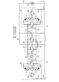
- FIG. 1 is a cross-sectional view showing a valve device according to Embodiment 1 of the present invention.
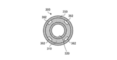
- 2 is a cross-sectional view taken along line XX in FIG. 3 is a cross-sectional view taken along line YY in FIG.
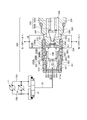
- FIG. 4 is a hydraulic circuit diagram showing an application example of the valve device shown in FIG.
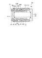
- FIG. 5 is a cross-sectional view showing a main part of the valve device according to the second embodiment of the present invention.
- FIG. 6 is a cross-sectional view showing a main part of a valve device according to Embodiment 3 of the present invention.
- FIG. 1 shows a valve device according to Embodiment 1 of the present invention, and illustrates a valve device used as a charge relief valve 300 in the hydraulic circuit shown in FIG.
- the hydraulic circuit in FIG. 4 is for running a work vehicle used as a construction machine such as a bulldozer, and includes an individual hydraulic transmission unit 10 between the engine 1 and the left and right drive wheels 2. Since the hydraulic transmission unit 10 provided for each drive wheel 2 has the same configuration, only one of them will be described below, and the other will be given the same reference numeral and description thereof will be omitted. .
- the hydraulic transmission unit 10 is a so-called HST (Hydro-Static Transmission), and includes a hydraulic pump 11 driven by the engine 1 and a traveling hydraulic motor 12 driven by oil supplied from the hydraulic pump 11. And a pair of main oil passages 13A and 13B constituting a closed circuit for circulating and supplying oil between the hydraulic pump 11 and the hydraulic motor 12.
- HST Hydro-Static Transmission
- the charge unit 20 is attached to the hydraulic transmission unit 10.
- the charge unit 20 has a charge pump 21 driven by the engine 1, one end connected to the discharge port of the charge pump 21, and the other end via a check valve 23, the first main oil passage 13 ⁇ / b> A and the second main oil passage 13 ⁇ / b> A.
- a charge oil passage 22 branched and connected to each of the oil passages 13B, a tank oil passage 24 extending from the charge oil passage 22 to reach the oil tank T, and a charge safety valve 25 interposed in the tank oil passage 24 It is prepared.
- the hydraulic power transmission unit 10 is provided with a flushing unit 30 in the motor case M of the hydraulic motor 12, as shown in FIG.
- the flushing unit 30 operates according to the differential pressure between the pair of main oil passages 13A and 13B and selects the low-pressure side main oil passage 13A or 13B, and the low-pressure side selected by the low-pressure selection valve 31
- the main oil passage 13A or 13B is communicated with the inside of the motor case M, the relief oil passage 33 for connecting the inside of the motor case M to the oil tank T, and the case drain oil passage 32.
- a charge relief valve 300 is provided.
- the charge relief valve 300 includes a valve body 310, a slide member 320, and a pilot valve unit 330.
- the valve main body 310 has a main body oil passage 311 in the center, and one end of the main body oil passage 311 opens as an introduction port 311a, and a support wall 312 has a portion positioned on the other end side of the main body oil passage 311. It has a cylindrical shape.
- a pilot lead-out hole 313 having a smaller diameter than the main body oil passage 311 is provided at the center of the support wall 312.
- the cover member 350 is a cylindrical member having an inner diameter that can be brought into close contact with the outer peripheral surface of the valve body 310.
- the cover member 350 has an outer periphery of the valve main body 310 in a state where movement in the axial direction is restricted by a step portion 310 a formed on the outer peripheral surface of the valve main body 310 and a ring member 342 fitted to the outer peripheral surface of the valve main body 310. It is attached to.
- a plurality of outlets 351 are formed in a portion of the cover member 350 corresponding to the fifth chamber 310D. In the first embodiment, the outlets 351 are provided at 12 positions on the same circumference at equal intervals.
- the relief valve 300 in which the secondary chamber 310A, the tertiary chamber 310B, the fourth chamber 310C, and the fifth chamber 310D are provided in the valve body 310 as the expansion chamber is illustrated as an example.
- the number of chambers is not necessarily limited to this, and may be less than four as long as it is plural, or more than four expansion chambers may be provided as shown in a second embodiment described later. Absent.
- FIG. 5 shows a valve device according to Embodiment 2 of the present invention.
- the valve device exemplified here is used as the charge relief valve 300 ′ in the hydraulic circuit shown in FIG. 4 as in the first embodiment, and is different from the first embodiment only in the number of expansion chambers.
- the valve body 310 has a secondary chamber (discharge port) 310A, a tertiary chamber 310B, a fourth chamber 310C, a fifth chamber 310D, and a sixth chamber 310E as expansion chambers. It is provided.
- This configuration is the same as that of the first embodiment, and a sixth chamber 310E is provided on the outer peripheral surface of the valve main body 310 that is further on the proximal side than the fifth chamber 310D.
- the configuration of the sixth chamber 310E is that the annular recess is formed on the outer peripheral surface of the valve body 310, and the cover member 350 is mounted on the outer periphery of the valve body 310.
- a 5-6 communication hole 364 is provided in a wall portion located between the fifth chamber 310D and the sixth chamber 310E.
- the 5-6 communication hole 364 and the 4-5 communication hole 363 are provided at positions shifted from each other in the circumferential direction, and the oil that has passed through the 4-5 communication hole 362 does not reach the 5-6 communication hole 364 directly. Absent. Further, the outlet 351 of the cover member 350 is formed only at a portion corresponding to the sixth chamber 310E. Note that the same reference numerals in the second embodiment denote the same components as those in the first embodiment, and a detailed description thereof will be omitted.
- the oil is circulated and supplied to the hydraulic motor 12 through the pair of main oil passages 13 A and 13 B by the drive of the hydraulic pump 11, and the main pressure on the low pressure side selected by the low pressure selection valve 31.
- the pressure in the oil passage 13A or 13B becomes higher than the set pressure of the relief spring 340, the slide member 320 maintained at the blocking position slides, and eventually the slide member 320 shifts to the communication position.
- the oil in the primary chamber 321A is discharged to the secondary chamber 310A through the valve hole 323, and the 2-3 communication hole 361, the tertiary chamber 310B, the 3-4 communication hole 362, After sequentially passing through the fourth chamber 310C, the 4-5 communication hole 363, the fifth chamber 310D, the 5-6 communication hole 364, the sixth chamber 310E, and the outlet 351 of the cover member 350, the case drain oil passage 32 is passed through. It is discharged into the motor case M. Further, the oil in the motor case M is discharged to the oil tank T through the relief oil passage 33.
- the oil in the primary chamber 321A expands when it passes through the valve hole 323 and reaches the secondary chamber 310A.
- the oil in the secondary chamber 310A expands when it passes through the 2-3 communication hole 361 and reaches the tertiary chamber 310B, and the oil in the tertiary chamber 310B passes through the 3-4 communication hole 362 and becomes 4
- the oil in the fourth chamber 310C expands when it reaches the fifth chamber 310D through the 4-5 communication hole 363, and the oil in the fifth chamber 310D reaches 5-6. It expands when it reaches the sixth chamber 310E through the communication hole 364.
- the fourth chamber 410C and the fifth chamber 410D are sequentially arranged in the axial direction of the valve body 410 with respect to the third chamber 410B, and are formed to have a larger volume than the third chamber 410B.
- a plurality of 3-4 communication holes 462 are provided in the wall portion positioned between the tertiary chamber 410B and the fourth chamber 410C, and the wall portion positioned between the fourth chamber 410C and the fifth chamber 410D is provided on the wall portion.
- a plurality of 4-5 communication holes 463 are provided.
- the 3-4 communication hole 462 and the 4-5 communication hole 463 are notches opened along the axial direction of the valve main body 410 and on the outer peripheral surface of the valve main body 410, and constitute a throttle hole with the cover member 450. ing.
- the 3-4 communication hole 462 and the 4-5 communication hole 463 are provided at positions shifted from each other, and the oil that has passed through the 3-4 communication hole 462 does not reach the 4-5 communication hole 463 directly.
Landscapes
- Engineering & Computer Science (AREA)
- General Engineering & Computer Science (AREA)
- Mechanical Engineering (AREA)
- Safety Valves (AREA)
Abstract
下流の油圧回路にピーク圧が発生する事態を抑制するため、中心部に本体油路311を有した円筒状を成す弁本体310と、弁本体310に対してスライド可能に配設したスライド部材320と、弁本体310及びスライド部材320の間に介在し、スライド部材320が遮断位置を維持するように付勢するリリーフバネ340とを備え、本体油路311の油圧が予め設定したしきい値を超えた場合にリリーフバネ340の付勢力に抗してスライド部材320を遮断位置から連通位置に移動させるようにした弁装置において、弁本体310の排出口から導出口351に至るまでの油路に複数の膨張室310A,310B,310C,310Dを設けた。
Description
本発明は、弁装置に関するもので、特に油圧回路の油を排出する場合に用いられるリリーフ弁として好適な弁装置に関するものである。
ブルドーザ、ホイールローダ、フォークリフト等、建設機械として用いられる作業車両には、油圧ポンプから供給した油によって油圧モータを動作させ、油圧モータの出力軸に設けた走行車輪を回転させることによって走行するようにしたものがある。
この種の作業車両に適用される油圧回路では、低圧選択弁及びリリーフ弁を介して低圧油路の油を油圧モータのモータケースに排出し、さらにモータケースからリリーフ油路を介して油タンクに排出する(フラッシング)一方、チャージポンプによって油タンクの油を低圧油路に供給しており、油を系外に導出することで油圧モータの冷却を図るようにしている(例えば、特許文献1、特許文献2、特許文献3参照)。油圧回路のリリーフ弁としては、例えば、特許文献4の図12に記載されている構成のものや特許文献5の図1に記載されているものが、従来より一般的に適用されている。
ところで、上述した油圧回路では、作業車両をシャトル操作したり、急停止、走行停止操作を行ったりした場合、モータケースの内部にピーク圧が発生することが確認されている。モータケースに繰り返しピーク圧が発生した場合には、モータケースと出力軸との間のオイルシールに損傷を来たし、油漏れを招来するおそれがある。
特許文献5に記載されたリリーフ弁では、弁本体の油路を通過した後の油が一つの膨張室を通過するように構成されたものである。しかしながら、弁本体の油路を通過した油が単に一つの膨張室を通過するように構成したリリーフ弁では、油の圧力を大きく低減させることは困難であり、下流の油圧回路にピーク圧が発生する事態を抑制するには至らない。
本発明は、上記実情に鑑みて、下流の油圧回路にピーク圧が発生する事態をより確実に抑制することのできる弁装置を提供することを目的とする。
上記目的を達成するため、本発明に係る弁装置は、導入口及び導出口を有した弁本体と、前記弁本体の導入口及び導出口の間の本体油路にスライド可能に配設し、前記導入口及び前記導出口の間を遮断した遮断位置と前記導入口及び前記導出口の間を連通させた連通位置とに切り替わるスライド部材と、前記弁本体及び前記スライド部材の間に介在し、前記導入口及び前記導出口の間が遮断した状態を維持するように付勢する付勢手段とを備え、前記本体油路の油圧が予め設定したしきい値を超えた場合に前記付勢手段の付勢力に抗して前記スライド部材を遮断位置から連通位置に移動させるようにした弁装置において、前記弁本体には前記スライド部材よりも下流側となる油路に膨張室を複数形成し、かつ前記膨張室のすべてを通過した後の油を前記導出口から導出するように前記複数の膨張室を連通させたことを特徴とする。
また、本発明に係る弁装置は、中心部に本体油路を有した円筒状を成し、前記本体油路の一端が導入口となり、かつ内周面に排出口を有するとともに外周面に導出口を有した弁本体と、周壁に弁孔を有した円筒状を成し、前記弁孔が前記弁本体の排出口に対向した連通位置と前記弁孔が前記弁本体の周壁で閉塞された遮断位置とに切り替わる状態で前記弁本体の本体油路にスライド可能に配設したスライド部材と、前記弁本体及び前記スライド部材の間に介在し、前記スライド部材が遮断位置を維持するように付勢する付勢手段とを備え、前記本体油路の油圧が予め設定したしきい値を超えた場合に前記付勢手段の付勢力に抗して前記スライド部材を遮断位置から連通位置に移動させるようにした弁装置において、前記弁本体の前記排出口から前記導出口に至るまでの油路に膨張室を複数形成し、かつ前記膨張室のすべてを通過した後の油を前記導出口から導出するように前記複数の膨張室を連通させたことを特徴とする。
また、本発明は、上述した弁装置において、前記膨張室は、前記弁本体の外周面に形成した環状の凹部と、前記弁本体の外周面に装着したカバー部材との間に構成される環状空間を含むことを特徴とする。
また、本発明は、上述した弁装置において、前記環状空間を前記弁本体の軸方向に沿って複数並設し、かつ前記複数の環状空間の間に位置する前記弁本体の壁部分に前記環状空間を相互に連通する絞り孔を複数形成したことを特徴とする。
また、本発明は、上述した弁装置において、前記環状空間の両側に位置する壁部分には、互いに対向する位置を避けて前記絞り孔を設けたことを特徴とする。
本発明によれば、複数の膨張室を通過する際に油の圧力が漸次低減されるため、下流の油圧回路にピーク圧が発生する事態を確実に抑制することが可能となる。
以下、添付図面を参照しながら本発明に係る弁装置の好適な実施の形態について詳細に説明する。
(実施の形態1)
図1は、本発明の実施の形態1である弁装置を示したもので、図4に示す油圧回路においてチャージリリーフ弁300として用いられる弁装置を例示している。図4の油圧回路は、ブルドーザ等、建設機械として用いられる作業車両を走行させるためのもので、エンジン1と左右それぞれの駆動車輪2との間に個別の油圧伝動ユニット10を備えている。尚、駆動車輪2ごとに設けた油圧伝動ユニット10は、同様の構成を有したものであるため、以下においては一方についてのみ説明を行い、他方については同一の符号を付して説明を省略する。
図1は、本発明の実施の形態1である弁装置を示したもので、図4に示す油圧回路においてチャージリリーフ弁300として用いられる弁装置を例示している。図4の油圧回路は、ブルドーザ等、建設機械として用いられる作業車両を走行させるためのもので、エンジン1と左右それぞれの駆動車輪2との間に個別の油圧伝動ユニット10を備えている。尚、駆動車輪2ごとに設けた油圧伝動ユニット10は、同様の構成を有したものであるため、以下においては一方についてのみ説明を行い、他方については同一の符号を付して説明を省略する。
油圧伝動ユニット10は、いわゆるHST(Hydro-Static Transmission)と称されるもので、エンジン1によって駆動される油圧ポンプ11と、油圧ポンプ11から供給される油によって駆動される走行用の油圧モータ12と、これら油圧ポンプ11及び油圧モータ12の間に油を循環供給するための閉回路を構成する一対の主油路13A,13Bとを備えて構成してある。
油圧ポンプ11及び油圧モータ12は、それぞれ斜板もしくは斜軸の傾転角を変更することにより、押しのけ容積が変化する可変容量型のものである。油圧ポンプ11は、入力軸11aがエンジン1の出力軸1aに接続してある。油圧モータ12は、その出力軸12aが作業車両の駆動車輪2に接続してあり、駆動車輪2を回転駆動することで作業車両を走行させることができる。油圧モータ12の回転方向は、油圧ポンプ11からの油の供給方向に応じて変更することが可能であり、作業車両を前進、もしくは後進させることができる。尚、以下においては便宜上、一対の主油路13A,13Bを区別する場合、図4において油圧ポンプ11の上方に位置する吐出口に接続したものを「第1主油路13A」と称し、図4において油圧ポンプ11の下方に位置する吐出口に接続したものを「第2主油路13B」と称することとする。
この油圧伝動ユニット10には、チャージユニット20が付設してある。チャージユニット20は、エンジン1によって駆動されるチャージポンプ21と、一端部がチャージポンプ21の吐出口に接続し、他端部がそれぞれチェック弁23を介して第1主油路13A及び第2主油路13Bのそれぞれに分岐接続したチャージ油路22と、チャージ油路22から分岐延在して油タンクTに至るタンク油路24と、タンク油路24に介在させたチャージセフティ弁25とを備えて構成したものである。
このチャージユニット20では、エンジン1が駆動した場合にチャージポンプ21が常時駆動された状態となる。この状態において、例えば油圧ポンプ11や油圧モータ12の内部漏れに起因して、第1主油路13Aや第2主油路13Bの圧力がチャージセフティ弁25の設定圧力よりも低くなった場合には、該当する一方の主油路または両方の主油路13A,13Bに対してチャージポンプ21から油が補充される。第1主油路13A及び第2主油路13Bの圧力がいずれもチャージセフティ弁25の設定圧力以上であれば、チャージポンプ21から吐出された油は、タンク油路24及びチャージセフティ弁25を介して油タンクTに戻される。
さらに、油圧伝動ユニット10には、図4に示すように、油圧モータ12のモータケースMにフラッシングユニット30が設けてある。フラッシングユニット30は、一対の主油路13A,13Bの差圧に応じて動作して低圧側の主油路13Aもしくは13Bを選択する低圧選択弁31と、低圧選択弁31によって選択された低圧側の主油路13Aもしくは13BをモータケースMの内部に連通させるケースドレン油路32と、モータケースMの内部を油タンクTに接続させるリリーフ油路33と、ケースドレン油路32に介在させたチャージリリーフ弁300とを備えて構成したものである。
このフラッシングユニット30では、低圧選択弁31によって選択された低圧側となる主油路13Aもしくは13Bの圧力がチャージリリーフ弁300の設定圧力(<チャージセフティ弁25の設定圧力)よりも高くなった場合、低圧側主油路13Aもしくは13Bの油がモータケースMの内部に排出され、さらにモータケースMの油がリリーフ油路33を通じて油タンクTに排出されることになる。
上記のように構成した油圧伝動ユニット10では、エンジン1によって油圧ポンプ11が駆動されると、一対の主油路13A,13Bを通じて油圧モータ12に油が循環供給されることになり、油圧モータ12の駆動によって駆動車輪2が回転駆動し、作業車両が走行することになる。この間、上述したチャージユニット20及びフラッシングユニット30の動作により主油路13A,13Bを流れる油が系外に導出されて冷却され、油圧モータ12の冷却が図られることになる。
ここで、作業車両をシャトル操作したり、急停止、走行停止操作を行ったりした場合には、フラッシングユニット30の動作によってモータケースMに排出される油の量が増えるため、モータケースMの内部にピーク圧が発生し、例えばモータケースMと出力軸12aとの間のオイルシール(図示せず)に損傷を来たすおそれがある。
このため、この油圧回路では、図1に示すように、チャージリリーフ弁300に膨張室を設け、膨張室を通過させることで導出する際の油の圧力を低減し、上述した問題を解決するようにしている。以下、図1を参照しながら、チャージリリーフ弁300の具体的な構成について説明する。
図1に示すように、チャージリリーフ弁300は、弁本体310、スライド部材320及びパイロット弁ユニット330を備えている。弁本体310は、中心部に本体油路311を有し、本体油路311の一端が導入口311aとして開口する一方、本体油路311の他端部側に位置する部分に支持壁312を有した円筒状を成すものである。支持壁312の中心部には、本体油路311よりも小径のパイロット導出孔313が設けてある。
スライド部材320は、弁本体310において本体油路311の一端部側にスライド可能に配設した円筒状部材である。このスライド部材320には、中心孔321の中間部に隔壁322が設けてあるとともに、周壁に複数の弁孔323が設けてある。隔壁322は、スライド部材320の中心孔321をほぼ二等分する位置に形成したもので、中心部にパイロット導入孔324を有している。パイロット導入孔324は、パイロット導出孔313よりも小径の貫通孔である。弁孔323は、周壁において隔壁322よりも一端部側に位置する部分に径方向に沿って形成したものである。本実施の形態1では、同一の円周上の互いに等間隔となる4位置にそれぞれ弁孔323が設けてある。
このスライド部材320は、弁孔323を設けた一端部側が本体油路311の開口側に位置し、かつ隔壁322と弁本体310の支持壁312との間にリリーフバネ(付勢手段)340を介在させた状態で弁本体310の本体油路311にスライド可能に配設してある。本体油路311の導入口311a側内周面には、スライド部材320の脱落を防止するためのリング部材341が嵌着してある。これにより、スライド部材320は、リリーフバネ340のバネ力によって隔壁322が支持壁312から最も離隔し、かつ一端面が常時リング部材341に当接した状態に維持されることになる。リリーフバネ340のバネ力に抗してスライド部材320に外力を加えた場合には、弁本体310に対して隔壁322が支持壁312に近接する向きにスライド部材320を移動させることが可能となる。
パイロット弁ユニット330は、円筒状を成すユニット本体331と、ユニット本体331の内部に収容したポペット部材332及びポペットバネ333とを備えて構成したもので、ユニット本体331の先端面が支持壁312に当接した状態で弁本体310の他端部に装着してある。ユニット本体331の先端部には、パイロット連絡孔334と、複数のパイロット排出孔335とが設けてある。パイロット連絡孔334は、ユニット本体331の中心孔339から先端面に向けて形成したもので、弁本体310のパイロット導出孔313に連通している。図には明示していないが、パイロット連絡孔334の基端部には、ユニット本体331の中心孔339に近接するに従って漸次内径が増大する弁座が形成してある。パイロット排出孔335は、ユニット本体331の中心孔339からそれぞれ径方向に沿って形成したもので、ユニット本体331の外周面に開口している。
ポペット部材332は、細径の円柱状を成すポペットロッド332aの先端部にポペット332bを備えたものである。ポペット332bは、基端部がポペットロッド332aよりも太径の円柱状を成し、かつ先端部が先端に向かうに従って漸次細径となるテーパ状を成すものである。このポペット部材332は、ポペット332bのテーパ状を成す周面をユニット本体331のパイロット連絡孔334に設けた弁座に離接可能となる状態でユニット本体331の中心孔339に移動可能に配設してある。ポペットバネ333は、ユニット本体331の基端部に螺合させた栓部材336とポペット部材332のポペット332bの間に介在し、ポペット332bのテーパ状を成す周面を常時パイロット連絡孔334の弁座に当接させるように機能するものである。尚、図1中の符号337は、パイロット連絡孔334に設けたオイルフィルタである。
一方、チャージリリーフ弁300は、弁本体310に膨張室として2次室(排出口)310A、3次室310B、4次室310C及び5次室310Dが設けてある。2次室310Aは、弁本体310の内周面に環状の凹部を形成することにより、スライド部材320の外周面との間に構成される環状空間である。この2次室310Aは、スライド部材320の一端面がリング部材341に当接した状態にある場合、スライド部材320の弁孔323との間が遮断される(遮断位置)一方、リリーフバネ340のバネ力に抗してスライド部材320を支持壁312に近接する方向にスライドさせた場合にスライド部材320の弁孔323に開口し、スライド部材320において隔壁322よりも一端部側に位置する中心孔の部分(以下、「1次室321A」という)と連通する(連通位置)ように形成してある。
3次室310B、4次室310C及び5次室310Dは、それぞれ弁本体310の外周面に軸方向に沿って環状の凹部を並設し、かつ弁本体310の外周にカバー部材350を装着することにより、カバー部材350とそれぞれの凹部との間に構成される環状空間である。図からも明らかなように、3次室310Bは、2次室310Aの外周側となる位置に形成してあり、径方向に沿って設けた複数の2-3連通孔361を介して2次室310Aと連通している。本実施の形態1では、互いに等間隔となる6位置に2次室310Aと3次室310Bとの間を連通する2-3連通孔361が設けてある。
4次室310C及び5次室310Dは、3次室310Bに対して弁本体310の軸方向に順次並設したもので、それぞれ3次室310Bよりも大きな容積を有するように形成してある。3次室310Bと4次室310Cとの間に位置する壁部には複数の3-4連通孔362が設けてあり、4次室310Cと5次室310Dとの間に位置する壁部分には複数の4-5連通孔363が設けてある。3-4連通孔362及び4-5連通孔363は、それぞれ弁本体310の軸方向に沿い、かつ弁本体310外周面に開口した切欠であり、カバー部材350との間に絞り孔を構成している。本実施の形態1では、図2及び図3に示すように、互いに等間隔となる4位置にそれぞれ3-4連通孔362及び4-5連通孔363が設けてある。3-4連通孔362及び4-5連通孔363は、互いに円周方向に45°ずれた位置に設けてあり、3-4連通孔362を通過した油が直接4-5連通孔363に至ることはない。
カバー部材350は、図1に示すように、弁本体310の外周面に密着することのできる内径を有した円筒状部材である。このカバー部材350は、弁本体310の外周面に構成した段部310aと弁本体310の外周面に嵌着したリング部材342とによって軸方向への移動が規制された状態で弁本体310の外周に装着してある。カバー部材350において5次室310Dに対応する部位には、複数の導出口351が形成してある。本実施の形態1では、同一円周上の互いに等間隔となる12位置にそれぞれ導出口351が設けてある。
上述の構成を有するチャージリリーフ弁300には、1次室321Aがケースドレン油路32によって低圧選択弁31の導出口に接続され、かつカバー部材350に設けた導出口351及びパイロット弁ユニット330のパイロット排出孔335がそれぞれケースドレン油路32によってモータケースMの内部に接続される。
いま、油圧ポンプ11の駆動により、一対の主油路13A,13Bを介して油圧モータ12に油が循環供給され、低圧選択弁31によって選択された低圧側となる主油路13Aもしくは13Bの圧力がリリーフバネ340の設定圧力よりも高くなると、遮断位置に維持されていたスライド部材320がスライドし、やがてスライド部材320が連通位置に移行する。この間、1次室321Aの圧力がポペットバネ333の設定圧力よりも高くなると、パイロット導入孔324を通過した油によってポペット332bがパイロット連絡孔334の弁座から離隔することになる。この結果、弁本体310の支持壁312とスライド部材320の隔壁322との間の空間の油がパイロット排出孔335からモータケースMの内部に排出され、弁本体310の支持壁312とスライド部材320の隔壁322との間の空間の圧力が低下するため、スライド部材320が移動することになる。
スライド部材320が連通位置に移動すると、1次室321Aの油が弁孔323を介して2次室310Aに排出され、2-3連通孔361、3次室310B、3-4連通孔362、4次室310C、4-5連通孔363、5次室310D及びカバー部材350の導出口351を順次通過した後、ケースドレン油路32を介してモータケースMの内部に排出される。さらにモータケースMの油は、リリーフ油路33を通じて油タンクTに排出される。
ここで、1次室321Aの油は、弁孔323を通過して2次室310Aに到達した際に膨張する。同様に、2次室310Aの油は2-3連通孔361を通過して3次室310Bに到達した際に膨張し、3次室310Bの油は3-4連通孔362を通過して4次室310Cに到達した際に膨張し、4次室310Cの油は4-5連通孔363を通過して5次室310Dに到達した際に膨張する。従って、作業車両をシャトル操作したり、急停止、走行停止操作を行ったりした場合にも、1次室321Aの油は、モータケースMの内部に排出されるまでの間に圧力が大きく低減されることになり、モータケースMの内部でのピーク圧の発生を抑制することができ、モータケースMと出力軸12aとの間のオイルシール(図示せず)に損傷を来たすおそれがなくなる。
尚、上述した実施の形態1では、膨張室として弁本体310に2次室310A、3次室310B、4次室310C及び5次室310Dを設けたリリーフ弁300を例示しているが、膨張室の数は必ずしもこれに限定されず、複数であれば4つよりも少なくても良いし、後述する実施の形態2に示すように、4つより多くの膨張室を設けるようにしても構わない。
(実施の形態2)
図5は、本発明の実施の形態2である弁装置を示したものである。ここで例示する弁装置は、実施の形態1と同様、図4に示す油圧回路においてチャージリリーフ弁300′として用いられるもので、実施の形態1とは膨張室の数のみが異なっている。
図5は、本発明の実施の形態2である弁装置を示したものである。ここで例示する弁装置は、実施の形態1と同様、図4に示す油圧回路においてチャージリリーフ弁300′として用いられるもので、実施の形態1とは膨張室の数のみが異なっている。
すなわち、実施の形態2のチャージリリーフ弁300′では、弁本体310に膨張室として2次室(排出口)310A、3次室310B、4次室310C、5次室310D及び6次室310Eが設けてある。2次室310A、3次室310B、4次室310C、5次室310Dの構成及びそれぞれの室の間に設けた2-3連通孔361、3-4連通孔362、4-5連通孔363の構成は実施の形態1と同様であり、弁本体310において5次室310Dよりもさらに基端側となる外周面に6次室310Eが設けてある。6次室310Eの構成が弁本体310の外周面に環状の凹部を形成し、かつ弁本体310の外周にカバー部材350を装着することによって構成する点は、3次室310B、4次室310C、5次室310Dと同様である。5次室310Dと6次室310Eとの間に位置する壁部分には、5-6連通孔364が設けてある。5-6連通孔364及び4-5連通孔363は、互いに円周方向にずれた位置に設けてあり、4-5連通孔362を通過した油が直接5-6連通孔364に至ることはない。また、カバー部材350の導出口351は、6次室310Eに対応する部位にのみ形成してある。尚、実施の形態2において実施の形態1と同様の構成については同一の符号を付して詳細説明を省略する。
このチャージリリーフ弁300′においても、油圧ポンプ11の駆動により、一対の主油路13A,13Bを介して油圧モータ12に油が循環供給され、低圧選択弁31によって選択された低圧側となる主油路13Aもしくは13Bの圧力がリリーフバネ340の設定圧力よりも高くなると、遮断位置に維持されていたスライド部材320がスライドし、やがてスライド部材320が連通位置に移行する。
スライド部材320が連通位置に移動すると、1次室321Aの油が弁孔323を介して2次室310Aに排出され、2-3連通孔361、3次室310B、3-4連通孔362、4次室310C、4-5連通孔363、5次室310D、5-6連通孔364、6次室310E及びカバー部材350の導出口351を順次通過した後、ケースドレン油路32を介してモータケースMの内部に排出される。さらにモータケースMの油は、リリーフ油路33を通じて油タンクTに排出される。
ここで、1次室321Aの油は、弁孔323を通過して2次室310Aに到達した際に膨張する。同様に、2次室310Aの油は2-3連通孔361を通過して3次室310Bに到達した際に膨張し、3次室310Bの油は3-4連通孔362を通過して4次室310Cに到達した際に膨張し、4次室310Cの油は4-5連通孔363を通過して5次室310Dに到達した際に膨張し、5次室310Dの油は5-6連通孔364を通過して6次室310Eに到達した際に膨張する。従って、作業車両をシャトル操作したり、急停止、走行停止操作を行ったりした場合にも、1次室321Aの油は、モータケースMの内部に排出されるまでの間に圧力が大きく低減されることになり、モータケースMの内部でのピーク圧の発生を抑制することができ、モータケースMと出力軸12aとの間のオイルシール(図示せず)に損傷を来たすおそれがなくなる。
尚、上述した実施の形態1及び実施の形態2では、パイロット弁ユニットを備えたパイロット作動方式のリリーフ弁を例示しているが、本発明は必ずしもパイロット作動方式の弁装置に限らず、例えば後述する実施の形態3のように、直接動作形の弁装置であっても良い。
(実施の形態3)
図6は、本発明の実施の形態3である弁装置を示したものである。ここで例示する弁装置は、図示せぬ油圧回路において背圧弁400として用いられるもので、弁本体410及びスライド部材420を備えている。弁本体410は、中心部に本体油路411を有した円筒状を成すもので、本体油路411の一端が導入口411Aとして開口する一方、本体油路411の他端が閉止ブロック430によって閉塞されている。図からも明らかなように、本体油路411の他端部は、一端部よりも内径が大きく形成してある。
図6は、本発明の実施の形態3である弁装置を示したものである。ここで例示する弁装置は、図示せぬ油圧回路において背圧弁400として用いられるもので、弁本体410及びスライド部材420を備えている。弁本体410は、中心部に本体油路411を有した円筒状を成すもので、本体油路411の一端が導入口411Aとして開口する一方、本体油路411の他端が閉止ブロック430によって閉塞されている。図からも明らかなように、本体油路411の他端部は、一端部よりも内径が大きく形成してある。
スライド部材420は、先端が閉塞する一方、開口した他端部の外周部にフランジ421を有した円筒状を成すもので、小径の先端部を介して弁本体410の本体油路411にスライド可能に配設してある。スライド部材420の先端側へのスライド位置は、フランジ421が本体油路411の内周段部411aに当接することにより、弁本体410の一端面よりも退行した位置に留まるように制限してある。また、スライド部材420と閉止ブロック430との間には、弁本体410に対してスライド部材420を先端側に向けて付勢する背圧バネ(付勢手段)440が設けてある。
一方、弁本体410には、膨張室として2次室(排出口)410A、3次室410B、4次室410C及び5次室410Dが設けてある。2次室410Aは、弁本体410の内周面に環状の凹部を形成することにより、スライド部材420の外周面との間に構成される環状空間である。この2次室410Aは、スライド部材420のフランジ421が本体油路411の内周段部411aに当接した状態にある場合、スライド部材420によって遮断される(遮断位置)一方、背圧バネ440のバネ力に抗してスライド部材420を閉止ブロック430に近接する方向にスライドさせた場合に開口し、弁本体410の本体油路411においてスライド部材420よりも一端部側に位置する部分(以下、「1次室411A」という)と連通する(連通位置)ように形成してある。
3次室410B、4次室410C及び5次室410Dは、それぞれ弁本体410の外周面に軸方向に沿って環状の凹部を並設し、かつ弁本体410の外周にカバー部材450を装着することにより、カバー部材450とそれぞれの凹部との間に構成される環状空間である。図からも明らかなように、3次室410Bは、2次室410Aの外周側となる位置に形成してあり、径方向に沿って設けた複数の2-3連通孔461を介して2次室410Aと連通している。本実施の形態3では、互いに等間隔となる6位置に2次室410Aと3次室410Bとの間を連通する2-3連通孔461が設けてある。
4次室410C及び5次室410Dは、3次室410Bに対して弁本体410の軸方向に順次並設したもので、それぞれ3次室410Bよりも大きな容積を有するように形成してある。3次室410Bと4次室410Cとの間に位置する壁部には複数の3-4連通孔462が設けてあり、4次室410Cと5次室410Dとの間に位置する壁部分には複数の4-5連通孔463が設けてある。3-4連通孔462及び4-5連通孔463は、それぞれ弁本体410の軸方向に沿い、かつ弁本体410外周面に開口した切欠であり、カバー部材450との間に絞り孔を構成している。3-4連通孔462及び4-5連通孔463は、互いにずれた位置に設けてあり、3-4連通孔462を通過した油が直接4-5連通孔463に至ることはない。
カバー部材450は、弁本体410の外周面に密着することのできる内径を有した円筒状部材である。このカバー部材450は、弁本体410の外周面に構成した外周段部410bと弁本体410の外周面に嵌着したリング部材442とによって軸方向への移動が規制された状態で弁本体410の外周に装着してある。カバー部材450において5次室410Dに対応する部位には、複数の導出口451が形成してある。
この背圧弁400では、弁本体410において1次室411Aの圧力が背圧バネ440の設定圧力よりも高くなると、遮断位置に維持されていたスライド部材420がスライドし、やがてスライド部材420が連通位置に移行する。スライド部材420が連通位置に移動すると、1次室411Aの油が2次室410Aに排出され、2-3連通孔461、3次室410B、3-4連通孔462、4次室410C、4-5連通孔463及び5次室410Dを介してカバー部材450の導出口451から排出される。尚、スライド部材420が連通位置に移動した場合には、スライド部材420の内部に含まれていた油等が閉止ブロック430に形成した中心孔430aを通じて図示せぬ油タンクに排出される。
ここで、1次室411Aの油は、弁孔323を通過して2次室410Aに到達した際に膨張する。同様に、2次室410Aの油は2-3連通孔461を通過して3次室410Bに到達した際に膨張し、3次室410Bの油は3-4連通孔462を通過して4次室410Cに到達した際に膨張し、4次室410Cの油は4-5連通孔463を通過して5次室410Dに到達した際に膨張する。従って、1次室411Aの油は、カバー部材450の導出口451から排出されるまでの間に圧力が大きく低減されることになり、下流の油圧回路にピーク圧が発生する事態を抑制することができるようになる。
尚、この背圧弁400においても、膨張室の数は、複数であれば4つよりも少なくても良いし、4つより多くしても構わない。
300 リリーフ弁
310,410 弁本体
310A,410A 2次室
310B,410B 3次室
310C,410C 4次室
310D,410D 5次室
310E 6次室
311,411 本体油路
320,420 スライド部材
323 弁孔
340 リリーフバネ
350,450 カバー部材
351,451 導出口
361,461 2-3連通孔
362,462 3-4連通孔
363,463 4-5連通孔
364 5-6連通孔
400 背圧弁
440 背圧バネ
310,410 弁本体
310A,410A 2次室
310B,410B 3次室
310C,410C 4次室
310D,410D 5次室
310E 6次室
311,411 本体油路
320,420 スライド部材
323 弁孔
340 リリーフバネ
350,450 カバー部材
351,451 導出口
361,461 2-3連通孔
362,462 3-4連通孔
363,463 4-5連通孔
364 5-6連通孔
400 背圧弁
440 背圧バネ
Claims (5)
- 導入口及び導出口を有した弁本体と、
前記弁本体の導入口及び導出口の間の本体油路にスライド可能に配設し、前記導入口及び前記導出口の間を遮断した遮断位置と前記導入口及び前記導出口の間を連通させた連通位置とに切り替わるスライド部材と、
前記弁本体及び前記スライド部材の間に介在し、前記導入口及び前記導出口の間が遮断した状態を維持するように付勢する付勢手段と
を備え、前記本体油路の油圧が予め設定したしきい値を超えた場合に前記付勢手段の付勢力に抗して前記スライド部材を遮断位置から連通位置に移動させるようにした弁装置において、
前記弁本体には前記スライド部材よりも下流側となる油路に膨張室を複数形成し、かつ前記膨張室のすべてを通過した後の油を前記導出口から導出するように前記複数の膨張室を連通させたことを特徴とする弁装置。 - 中心部に本体油路を有した円筒状を成し、前記本体油路の一端が導入口となり、かつ内周面に排出口を有するとともに外周面に導出口を有した弁本体と、
周壁に弁孔を有した円筒状を成し、前記弁孔が前記弁本体の排出口に対向した連通位置と前記弁孔が前記弁本体の周壁で閉塞された遮断位置とに切り替わる状態で前記弁本体の本体油路にスライド可能に配設したスライド部材と、
前記弁本体及び前記スライド部材の間に介在し、前記スライド部材が遮断位置を維持するように付勢する付勢手段と
を備え、前記本体油路の油圧が予め設定したしきい値を超えた場合に前記付勢手段の付勢力に抗して前記スライド部材を遮断位置から連通位置に移動させるようにした弁装置において、
前記弁本体の前記排出口から前記導出口に至るまでの油路に膨張室を複数形成し、かつ前記膨張室のすべてを通過した後の油を前記導出口から導出するように前記複数の膨張室を連通させたことを特徴とする弁装置。 - 前記膨張室は、前記弁本体の外周面に形成した環状の凹部と、前記弁本体の外周面に装着したカバー部材との間に構成される環状空間を含むことを特徴とする請求項2に記載の弁装置。
- 前記環状空間を前記弁本体の軸方向に沿って複数並設し、かつ前記複数の環状空間の間に位置する前記弁本体の壁部分に前記環状空間を相互に連通する絞り孔を複数形成したことを特徴とする請求項3に記載の弁装置。
- 前記環状空間の両側に位置する壁部分には、互いに対向する位置を避けて前記絞り孔を設けたことを特徴とする請求項4に記載の弁装置。
Priority Applications (1)
| Application Number | Priority Date | Filing Date | Title |
|---|---|---|---|
| PCT/JP2014/064340 WO2015181935A1 (ja) | 2014-05-29 | 2014-05-29 | 弁装置 |
Applications Claiming Priority (1)
| Application Number | Priority Date | Filing Date | Title |
|---|---|---|---|
| PCT/JP2014/064340 WO2015181935A1 (ja) | 2014-05-29 | 2014-05-29 | 弁装置 |
Publications (1)
| Publication Number | Publication Date |
|---|---|
| WO2015181935A1 true WO2015181935A1 (ja) | 2015-12-03 |
Family
ID=54698313
Family Applications (1)
| Application Number | Title | Priority Date | Filing Date |
|---|---|---|---|
| PCT/JP2014/064340 Ceased WO2015181935A1 (ja) | 2014-05-29 | 2014-05-29 | 弁装置 |
Country Status (1)
| Country | Link |
|---|---|
| WO (1) | WO2015181935A1 (ja) |
Cited By (4)
| Publication number | Priority date | Publication date | Assignee | Title |
|---|---|---|---|---|
| CN105370941A (zh) * | 2015-12-11 | 2016-03-02 | 四川嘉星燃气设备制造有限公司 | 一种燃气管路安全放散阀 |
| CN105370940A (zh) * | 2015-12-11 | 2016-03-02 | 四川嘉星燃气设备制造有限公司 | 一种安全放散阀 |
| CN106907368A (zh) * | 2017-04-28 | 2017-06-30 | 郑州华晶金刚石股份有限公司 | 超高压全自动泄压装置 |
| CN118934771A (zh) * | 2024-09-24 | 2024-11-12 | 燕山大学 | 阀芯运动可控的高速响应喷嘴挡板调速阀 |
Citations (3)
| Publication number | Priority date | Publication date | Assignee | Title |
|---|---|---|---|---|
| JPS56131076U (ja) * | 1980-03-07 | 1981-10-05 | ||
| JPS59190582A (ja) * | 1983-04-12 | 1984-10-29 | Daikin Ind Ltd | 油圧制御弁 |
| JPH0882302A (ja) * | 1994-09-12 | 1996-03-26 | Shin Caterpillar Mitsubishi Ltd | ネガティブ流量制御装置 |
-
2014
- 2014-05-29 WO PCT/JP2014/064340 patent/WO2015181935A1/ja not_active Ceased
Patent Citations (3)
| Publication number | Priority date | Publication date | Assignee | Title |
|---|---|---|---|---|
| JPS56131076U (ja) * | 1980-03-07 | 1981-10-05 | ||
| JPS59190582A (ja) * | 1983-04-12 | 1984-10-29 | Daikin Ind Ltd | 油圧制御弁 |
| JPH0882302A (ja) * | 1994-09-12 | 1996-03-26 | Shin Caterpillar Mitsubishi Ltd | ネガティブ流量制御装置 |
Cited By (4)
| Publication number | Priority date | Publication date | Assignee | Title |
|---|---|---|---|---|
| CN105370941A (zh) * | 2015-12-11 | 2016-03-02 | 四川嘉星燃气设备制造有限公司 | 一种燃气管路安全放散阀 |
| CN105370940A (zh) * | 2015-12-11 | 2016-03-02 | 四川嘉星燃气设备制造有限公司 | 一种安全放散阀 |
| CN106907368A (zh) * | 2017-04-28 | 2017-06-30 | 郑州华晶金刚石股份有限公司 | 超高压全自动泄压装置 |
| CN118934771A (zh) * | 2024-09-24 | 2024-11-12 | 燕山大学 | 阀芯运动可控的高速响应喷嘴挡板调速阀 |
Similar Documents
| Publication | Publication Date | Title |
|---|---|---|
| US9719609B2 (en) | Change-over valve | |
| US7254945B1 (en) | Operate check valve and hydraulic driving unit | |
| US10415710B2 (en) | Rotary valve and fluid pressure actuator unit including rotary valve | |
| US10119557B2 (en) | Hydraulic driving device | |
| US10233614B2 (en) | Fluid pressure control device | |
| US20200340210A1 (en) | Anti-reverse valve | |
| JP6779726B2 (ja) | ショックレスリリーフ弁 | |
| WO2021059614A1 (ja) | 流量制御弁 | |
| JP5561528B2 (ja) | リリーフ圧力変更機能付きリリーフバルブ | |
| JP2018003902A (ja) | 流体圧制御装置 | |
| WO2015141466A1 (ja) | ポンプ装置 | |
| JP4929471B2 (ja) | 可変容量ベーンポンプ | |
| JP6505630B2 (ja) | 方向制御弁 | |
| US20190376534A1 (en) | Electromagnetic pressure reducing valve and fluid pressure control device including electromagnetic pressure reducing valve | |
| JP5470180B2 (ja) | コントロールバルブ | |
| WO2019058711A1 (ja) | 液圧モータ制御装置 | |
| JP7393250B2 (ja) | 流体圧駆動ユニット | |
| JP7346037B2 (ja) | 流量制御弁 | |
| JP7134788B2 (ja) | 方向切換弁装置 | |
| JP2018151032A (ja) | 流体圧シリンダ及び流体圧駆動ユニット | |
| JP2012202268A (ja) | ベーンポンプ | |
| JP2019044878A (ja) | 油圧モータの冷却装置 | |
| JP2010255551A (ja) | 可変容量型ベーンポンプ | |
| JP2011169380A (ja) | 圧力補償付流量制御弁 | |
| JP2008039020A (ja) | 油圧モータ駆動装置 |
Legal Events
| Date | Code | Title | Description |
|---|---|---|---|
| 121 | Ep: the epo has been informed by wipo that ep was designated in this application |
Ref document number: 14893569 Country of ref document: EP Kind code of ref document: A1 |
|
| NENP | Non-entry into the national phase |
Ref country code: DE |
|
| NENP | Non-entry into the national phase |
Ref country code: JP |
|
| 122 | Ep: pct application non-entry in european phase |
Ref document number: 14893569 Country of ref document: EP Kind code of ref document: A1 |