WO2015181879A1 - Gas analyzer - Google Patents
Gas analyzer Download PDFInfo
- Publication number
- WO2015181879A1 WO2015181879A1 PCT/JP2014/063926 JP2014063926W WO2015181879A1 WO 2015181879 A1 WO2015181879 A1 WO 2015181879A1 JP 2014063926 W JP2014063926 W JP 2014063926W WO 2015181879 A1 WO2015181879 A1 WO 2015181879A1
- Authority
- WO
- WIPO (PCT)
- Prior art keywords
- gas
- light
- unit
- absorbing
- absorption
- Prior art date
Links
- 239000007789 gas Substances 0.000 claims abstract description 1188
- CBENFWSGALASAD-UHFFFAOYSA-N Ozone Chemical compound [O-][O+]=O CBENFWSGALASAD-UHFFFAOYSA-N 0.000 claims abstract description 67
- 238000005259 measurement Methods 0.000 claims abstract description 66
- MWUXSHHQAYIFBG-UHFFFAOYSA-N Nitric oxide Chemical compound O=[N] MWUXSHHQAYIFBG-UHFFFAOYSA-N 0.000 claims abstract description 56
- JCXJVPUVTGWSNB-UHFFFAOYSA-N nitrogen dioxide Inorganic materials O=[N]=O JCXJVPUVTGWSNB-UHFFFAOYSA-N 0.000 claims abstract description 39
- MGWGWNFMUOTEHG-UHFFFAOYSA-N 4-(3,5-dimethylphenyl)-1,3-thiazol-2-amine Chemical compound CC1=CC(C)=CC(C=2N=C(N)SC=2)=C1 MGWGWNFMUOTEHG-UHFFFAOYSA-N 0.000 claims abstract description 37
- 238000006243 chemical reaction Methods 0.000 claims abstract description 33
- RAHZWNYVWXNFOC-UHFFFAOYSA-N Sulphur dioxide Chemical compound O=S=O RAHZWNYVWXNFOC-UHFFFAOYSA-N 0.000 claims abstract description 30
- 238000010521 absorption reaction Methods 0.000 claims description 160
- 238000001514 detection method Methods 0.000 claims description 51
- 230000005540 biological transmission Effects 0.000 claims description 47
- 230000003647 oxidation Effects 0.000 claims description 47
- 238000007254 oxidation reaction Methods 0.000 claims description 47
- 238000012545 processing Methods 0.000 claims description 30
- 238000012937 correction Methods 0.000 claims description 18
- 230000003750 conditioning effect Effects 0.000 claims description 8
- 238000009826 distribution Methods 0.000 claims description 8
- IJGRMHOSHXDMSA-UHFFFAOYSA-N Atomic nitrogen Chemical compound N#N IJGRMHOSHXDMSA-UHFFFAOYSA-N 0.000 claims description 7
- 229910001873 dinitrogen Inorganic materials 0.000 claims description 7
- GQPLMRYTRLFLPF-UHFFFAOYSA-N Nitrous Oxide Chemical compound [O-][N+]#N GQPLMRYTRLFLPF-UHFFFAOYSA-N 0.000 claims description 6
- 230000000644 propagated effect Effects 0.000 claims description 4
- 239000001272 nitrous oxide Substances 0.000 claims description 3
- ZWWCURLKEXEFQT-UHFFFAOYSA-N dinitrogen pentaoxide Chemical compound [O-][N+](=O)O[N+]([O-])=O ZWWCURLKEXEFQT-UHFFFAOYSA-N 0.000 abstract 4
- 238000002156 mixing Methods 0.000 description 37
- 238000004458 analytical method Methods 0.000 description 32
- 239000002994 raw material Substances 0.000 description 25
- 238000010586 diagram Methods 0.000 description 15
- 230000003287 optical effect Effects 0.000 description 12
- 230000031700 light absorption Effects 0.000 description 10
- 230000000694 effects Effects 0.000 description 7
- 230000001965 increasing effect Effects 0.000 description 7
- 238000004364 calculation method Methods 0.000 description 6
- 238000000034 method Methods 0.000 description 5
- 229910052717 sulfur Inorganic materials 0.000 description 4
- 230000007423 decrease Effects 0.000 description 3
- 239000000463 material Substances 0.000 description 3
- 230000001902 propagating effect Effects 0.000 description 3
- 239000000126 substance Substances 0.000 description 3
- 238000002834 transmittance Methods 0.000 description 3
- YZCKVEUIGOORGS-OUBTZVSYSA-N Deuterium Chemical compound [2H] YZCKVEUIGOORGS-OUBTZVSYSA-N 0.000 description 2
- MYMOFIZGZYHOMD-UHFFFAOYSA-N Dioxygen Chemical compound O=O MYMOFIZGZYHOMD-UHFFFAOYSA-N 0.000 description 2
- XUIMIQQOPSSXEZ-UHFFFAOYSA-N Silicon Chemical compound [Si] XUIMIQQOPSSXEZ-UHFFFAOYSA-N 0.000 description 2
- 238000002835 absorbance Methods 0.000 description 2
- 238000000862 absorption spectrum Methods 0.000 description 2
- 230000032683 aging Effects 0.000 description 2
- 230000008033 biological extinction Effects 0.000 description 2
- 238000002485 combustion reaction Methods 0.000 description 2
- 238000001739 density measurement Methods 0.000 description 2
- 229910052805 deuterium Inorganic materials 0.000 description 2
- 229910001882 dioxygen Inorganic materials 0.000 description 2
- 238000004868 gas analysis Methods 0.000 description 2
- 238000000691 measurement method Methods 0.000 description 2
- 238000002310 reflectometry Methods 0.000 description 2
- 230000035945 sensitivity Effects 0.000 description 2
- 229910052710 silicon Inorganic materials 0.000 description 2
- 239000010703 silicon Substances 0.000 description 2
- 239000007787 solid Substances 0.000 description 2
- 229910052724 xenon Inorganic materials 0.000 description 2
- FHNFHKCVQCLJFQ-UHFFFAOYSA-N xenon atom Chemical compound [Xe] FHNFHKCVQCLJFQ-UHFFFAOYSA-N 0.000 description 2
- 229910002704 AlGaN Inorganic materials 0.000 description 1
- UGFAIRIUMAVXCW-UHFFFAOYSA-N Carbon monoxide Chemical compound [O+]#[C-] UGFAIRIUMAVXCW-UHFFFAOYSA-N 0.000 description 1
- 229910000831 Steel Inorganic materials 0.000 description 1
- 238000003915 air pollution Methods 0.000 description 1
- -1 aluminum nitride compound Chemical class 0.000 description 1
- QVGXLLKOCUKJST-UHFFFAOYSA-N atomic oxygen Chemical compound [O] QVGXLLKOCUKJST-UHFFFAOYSA-N 0.000 description 1
- 239000004566 building material Substances 0.000 description 1
- WUKWITHWXAAZEY-UHFFFAOYSA-L calcium difluoride Chemical compound [F-].[F-].[Ca+2] WUKWITHWXAAZEY-UHFFFAOYSA-L 0.000 description 1
- 229910001634 calcium fluoride Inorganic materials 0.000 description 1
- 239000000571 coke Substances 0.000 description 1
- 239000000567 combustion gas Substances 0.000 description 1
- 238000006477 desulfuration reaction Methods 0.000 description 1
- 230000023556 desulfurization Effects 0.000 description 1
- 230000006866 deterioration Effects 0.000 description 1
- 238000007599 discharging Methods 0.000 description 1
- 238000005516 engineering process Methods 0.000 description 1
- 230000002708 enhancing effect Effects 0.000 description 1
- 230000007613 environmental effect Effects 0.000 description 1
- 230000001747 exhibiting effect Effects 0.000 description 1
- 238000002474 experimental method Methods 0.000 description 1
- 239000002360 explosive Substances 0.000 description 1
- 230000002349 favourable effect Effects 0.000 description 1
- 238000000855 fermentation Methods 0.000 description 1
- 230000004151 fermentation Effects 0.000 description 1
- 239000003546 flue gas Substances 0.000 description 1
- 235000012055 fruits and vegetables Nutrition 0.000 description 1
- 230000020169 heat generation Effects 0.000 description 1
- 238000010438 heat treatment Methods 0.000 description 1
- 238000004519 manufacturing process Methods 0.000 description 1
- 244000005700 microbiome Species 0.000 description 1
- 239000003921 oil Substances 0.000 description 1
- 239000001301 oxygen Substances 0.000 description 1
- 229910052760 oxygen Inorganic materials 0.000 description 1
- 239000008188 pellet Substances 0.000 description 1
- 230000008635 plant growth Effects 0.000 description 1
- 230000002265 prevention Effects 0.000 description 1
- 239000010453 quartz Substances 0.000 description 1
- 239000012495 reaction gas Substances 0.000 description 1
- 230000005070 ripening Effects 0.000 description 1
- 239000004065 semiconductor Substances 0.000 description 1
- VYPSYNLAJGMNEJ-UHFFFAOYSA-N silicon dioxide Inorganic materials O=[Si]=O VYPSYNLAJGMNEJ-UHFFFAOYSA-N 0.000 description 1
- 238000005245 sintering Methods 0.000 description 1
- 238000001179 sorption measurement Methods 0.000 description 1
- 229910001220 stainless steel Inorganic materials 0.000 description 1
- 239000010935 stainless steel Substances 0.000 description 1
- 239000010959 steel Substances 0.000 description 1
- 238000003860 storage Methods 0.000 description 1
- 239000002341 toxic gas Substances 0.000 description 1
Images


Classifications
-
- G—PHYSICS
- G01—MEASURING; TESTING
- G01N—INVESTIGATING OR ANALYSING MATERIALS BY DETERMINING THEIR CHEMICAL OR PHYSICAL PROPERTIES
- G01N21/00—Investigating or analysing materials by the use of optical means, i.e. using sub-millimetre waves, infrared, visible or ultraviolet light
- G01N21/17—Systems in which incident light is modified in accordance with the properties of the material investigated
- G01N21/25—Colour; Spectral properties, i.e. comparison of effect of material on the light at two or more different wavelengths or wavelength bands
- G01N21/31—Investigating relative effect of material at wavelengths characteristic of specific elements or molecules, e.g. atomic absorption spectrometry
- G01N21/33—Investigating relative effect of material at wavelengths characteristic of specific elements or molecules, e.g. atomic absorption spectrometry using ultraviolet light
Definitions
- the present invention relates to a gas analyzer that measures gas concentrations of a plurality of gases contained in a sample gas.
- Patent Literature 1 discloses a conventional gas analyzer. This prior art will be described with reference to the drawings.
- FIG. 12 is a conventional absorption spectrometer described in Patent Document 1.
- the absorption spectrometer 300 measures the concentration of NO 2 gas (nitrogen dioxide gas) contained in the sample gas by the ultraviolet absorption method.
- the absorption spectrometer 300 includes an ultraviolet light source 301, a visible light source 302, a reference cell 303, a sample cell 304, a light guide mechanism 305, a light detection unit 306, a control unit 307, and a calculation unit 308. ing.
- the ultraviolet light source 301 is a light emitting diode that emits ultraviolet light.
- the central emission wavelength of the ultraviolet light is 360 to 400 nm, and is included in the absorption wavelength band of NO 2 gas as shown in the wavelength-absorption coefficient characteristic diagram of FIG. Upon irradiation of such ultraviolet light to NO 2 gas, absorption by NO 2 gas.
- the visible light source 302 is a light emitting diode that emits visible light.
- the central emission wavelength of visible light is larger than the wavelength of ultraviolet light and is included in the absorption wavelength band of NO 2 gas as shown in the wavelength-absorption coefficient characteristic diagram of FIG. Is different. As such it absorbance of visible light by the NO 2 gas is irradiated to NO 2 gas is carried out, when compared with the absorption of ultraviolet light by the above-mentioned NO 2 gas, the absorbance of visible light is reduced by the NO 2 gas, The wavelength of the visible light source 302 is set.
- the reference cell 303 is filled with a reference gas.
- This reference gas is, for example, nitrogen gas.
- Ultraviolet light or visible light is incident through the windows 303a and 303b.
- the sample cell 304 is supplied with a sample gas that is a measurement target. Ultraviolet light or visible light is incident through the windows 304a and 304b. The sample gas flows into the sample cell 304 through the gas inlet 304c and flows out through the gas outlet 304d.
- the light guide mechanism 305 includes a mirror 305a and a half mirror 305b.
- the ultraviolet light from the ultraviolet light source 301 and the visible light from the visible light source 302 are reflected by the half mirror 305b and the mirror 305a and introduced into the reference cell 303 from one end side through the window 303a of the reference cell 303.
- ultraviolet light from the ultraviolet light source 301 and visible light from the visible light source 302 are transmitted through the half mirror 305 b and introduced into the sample cell 304 from one end side through the window 304 a of the sample cell 304.
- absorption by NO 2 gas is performed.
- the light detection unit 306 includes light detectors 306a and 306b.
- the photodetector 306a is provided on the other end side of the reference cell 303, and detects ultraviolet light or visible light transmitted through the window 303b of the reference cell 303.
- the photodetector 306b is provided on the other end side of the sample cell 304, and detects ultraviolet light and visible light transmitted through the window 304b of the sample cell 304.
- the control unit 307 causes the ultraviolet light source 301 and the visible light source 302 to emit light in a time-sharing manner.
- the light detection unit 306 obtains two-wavelength transmitted light that passes through the reference cell 303 and the sample cell 304. As a result, there are two optical paths and two wavelengths, and four signals are obtained: a sample signal for ultraviolet transmitted light, a sample signal for visible transmitted light, a reference signal for ultraviolet transmitted light, and a reference signal for visible transmitted light.
- the calculation unit 308 receives the four signals from the light detection unit 306 via the control unit 307, and calculates the NO 2 gas concentration based on the four signals. Thereby, compensation of drift of the ultraviolet light source 301 and the visible light source 302, correction of interference of other components other than the measurement component, correction of light amount decrease due to dirt and clouding of the transmission windows 304a and 304b of the sample cell 304, correction of sensitivity drift, Make it possible.
- the NO 2 gas concentration can be calculated after performing these corrections, and the measurement accuracy is improved.
- the measurable gas component is limited to one type. Therefore, in order to measure the concentration of two or more kinds of gases by the absorption method, a plurality of light emitting means for emitting a wavelength for absorbing a certain gas and a plurality of light receiving means for receiving the light are required for each gas. Become. Thus, in the prior art, there is a problem that the configuration increases in order to measure the concentration of two or more kinds of gases.
- the absorption of NO gas in the ultraviolet wavelength region includes the absorption of SO 2 gas and NO 2 gas, and is affected by other gases. Further, in the absorption of SO 2 gas in the ultraviolet wavelength region, there is also absorption of NO 2 gas, which is influenced by other gases.
- NO gas and SO 2 gas do not absorb, and visible transmitted light does not contain information about NO gas and SO 2 gas. Therefore, it is impossible to correct interference caused by NO gas or SO 2 gas, or to use it for concentration measurement of NO gas or SO 2 gas.
- the sample gas contains the gas components of NO gas and SO 2 gas as described above, it has been difficult to analyze the gas components of these NO gas and SO 2 gas in the prior art.
- a light source that emits light at a wavelength of 226 nm or less is required as shown in FIG.
- a light source that emits light in this wavelength region is limited to a lamp light source such as a deuterium lamp or a xenon lamp, or a light emitting diode using an aluminum nitride compound semiconductor (such as AlGaN).
- the former lamp light sources such as deuterium lamps and xenon lamps have problems with the heat generation, life and stability of the light source, and it is necessary to add an optical system such as a wavelength filter, and the apparatus is large and complicated.
- the latter light-emitting diode can reduce the size and simplification of the device as compared with the lamp light source, but has a short optical power and a short life. Further, in the wavelength region of wavelength 226 nm or less, various gases absorb light other than SO 2 gas and NO 2 gas, and it is difficult to remove the interference.
- an object of the present invention is to provide at least nitrogen monoxide gas (NO gas) and nitrogen dioxide gas (NO 2 gas) contained in the sample gas with a simple configuration. It is to provide a gas analyzer that can measure the gas concentration of two components. It is preferable to provide a gas analyzer capable of measuring the three component gas concentrations of sulfur dioxide gas (SO 2 gas), nitric oxide gas (NO gas) and nitrogen dioxide gas (NO 2 gas).
- SO 2 gas sulfur dioxide gas
- NO gas nitric oxide gas
- NO 2 gas nitrogen dioxide gas
- the present invention A gas analyzer that measures the gas concentrations of two components of nitrogen monoxide gas (NO gas) and nitrogen dioxide gas (NO 2 gas) contained in a sample gas, All nitric oxide gas contained in the sample gas (NO gas) by oxidation of ozone reacted in a nitrogen dioxide gas (NO 2 gas), further pentoxide a portion of the nitrogen dioxide gas (NO 2 gas) by oxidation of ozone
- a gas adjustment unit that performs an oxidation output that is output as a measurement target gas reacted with dinitrogen gas (N 2 O 5 gas), and a normal output that is output as a measurement target gas without any reaction;
- a light emitting part for absorbing O 3 gas that irradiates irradiation light for absorbing O 3 gas having a wavelength
- c m is calculated,
- the gas conditioning unit by using a signal from the transmitted light receiving unit and the reference light receiving unit when the emitting O 3 irradiation light gas absorption by controlling the oxidation output state, gas concentration c 3 of ozone (O 3 gas) To calculate The gas concentration of the nitrogen dioxide gas (NO 2 gas) is controlled using signals from the transmitted light receiving unit and the reference light receiving unit when the gas adjusting unit is controlled to the normal output state and the irradiation light for NO 2 gas absorption is emitted.
- NO 2 gas nitrogen dioxide gas
- c 2 is calculated, From the gas concentration c 0 of the ozone gas (O 3 gas) supplied, the gas concentration c 3 of the measured ozone (O 3 gas), the gas concentration in the reaction consumption calculated by subtracting the, in the gas as the object of measurement based on the equal to the gas concentration (c 1 + c 2 -c m ) / 2 gas concentration by adding gas concentration c 1 to nitric oxide gas (N 2 O 5 gas) of nitric oxide gas (NO gas)
- the gas analyzer was configured to calculate the gas concentration c 1 of nitric oxide gas (NO gas) from the calculated c 0 , c m , c 3 , c 2 .
- the present invention also provides: A gas analyzer that measures the concentration of three components of nitrogen monoxide gas (NO gas), nitrogen dioxide gas (NO 2 ), and sulfur dioxide gas (SO 2 gas) contained in a sample gas, All nitric oxide gas contained in the sample gas (NO gas) by oxidation of ozone reacted in a nitrogen dioxide gas (NO 2 gas), further pentoxide a portion of the nitrogen dioxide gas (NO 2 gas) by oxidation of ozone
- a gas adjustment unit that performs an oxidation output that is output as a measurement target gas reacted with dinitrogen gas (N 2 O 5 gas), and a normal output that is output as a measurement target gas without any reaction;
- a light emitting part for absorbing O 3 gas that irradiates light for absorbing O 3 gas
- the gas conditioning unit by using a signal from the transmitted light receiving unit and the reference light receiving unit when the emitting O 3 irradiation light gas absorption by controlling the oxidation output state, gas concentration c 3 of ozone (O 3 gas) And the gas concentration c s of sulfur dioxide gas (SO 2 gas),
- the gas concentration of the nitrogen dioxide gas (NO 2 gas) is controlled using signals from the transmitted light receiving unit and the reference light receiving unit when the gas adjusting unit is controlled to the normal output state and the irradiation light for NO 2 gas absorption is emitted.
- c 2 is calculated, The gas concentration of sulfur dioxide gas (SO 2 gas) is controlled using signals from the transmitted light receiving unit and the reference light receiving unit when the gas adjusting unit is controlled to the normal output state and the O 3 gas absorption irradiation light is emitted.
- c s is calculated, From the gas concentration c 0 of the ozone gas (O 3 gas) supplied, the gas concentration c 3 of the measured ozone (O 3 gas), the gas concentration in the reaction consumption calculated by subtracting the, in the gas as the object of measurement Based on the gas concentration c 1 of nitrogen monoxide gas (NO gas) plus the gas concentration (c 1 + c 2 ⁇ c m ) / 2 of nitrous oxide (N 2 O 5 gas) / 2.
- the gas analyzer was configured to calculate the gas concentration c 1 of nitric oxide gas (NO gas) from the calculated c 0 , c m , c 3 , c 2 .
- a correction unit connected to the reference light receiving unit, the NO 2 gas absorbing light emitting unit, and the O 3 gas absorbing light emitting unit;
- the reference light receiving unit receives the irradiation light for absorbing NO 2 gas and the irradiation light for absorbing O 3 gas partially reflected by the partial reflection unit, and outputs a detection signal to the correction unit,
- the correction unit may be a gas analyzer that outputs a drive current that suppresses fluctuations based on the detection signal to the NO 2 gas absorption light emission unit and the O 3 gas absorption light emission unit.
- Collecting the O 3 irradiation light gas absorption from the NO 2 lens and the O 3 gas absorption for the light emitting portion condenses the NO 2 gas absorption for the irradiation light from the gas absorption for the light emitting portion is incident on the gas flow cell
- a gas analyzer that includes a lens that emits light and enters the gas flow cell may be used.
- a light emitting unit that integrally accommodates the NO 2 gas absorbing light emitting unit and the O 3 gas absorbing light emitting unit adjacent to each other;
- a lens for incident condenses O 3 irradiation light gas absorption from the NO 2 NO 2 gas absorption irradiation light and the O 3 gas absorption for the light emitting portion of the gas absorption for the light emitting portion to the gas flow cell, It is good to make it a gas analyzer equipped with.
- the gas analyzer has a lens for collecting the irradiation light for absorbing NO 2 gas after passing through the gas circulation cell and the irradiation light for absorbing O 3 gas after passing through the gas circulation cell.
- the gas flow cell has a light transmission window on one side and a reflection part on the other side, and transmits the light transmission window and reflects the irradiation light for absorbing NO 2 gas and the irradiation light for absorbing O 3 gas at the reflection part.
- the transmitted light receiving unit detects the irradiation light for absorbing NO 2 gas and the irradiation light for absorbing O 3 gas reflected by the partial reflection unit so as to reciprocate in the detection space so as to pass through the light transmission window later.
- a good gas analyzer is recommended.
- a light emitting / receiving unit that integrally accommodates the NO 2 gas absorbing light emitting unit, the O 3 gas absorbing light emitting unit, and the transmitted light receiving unit adjacent to each other;
- the gas flow cell has a light transmission window on one side and a reflection part on the other side, The NO 2 gas absorption irradiation light and the O 3 gas absorption irradiation light emitted from the light emitting / receiving section through the light transmission window are reflected by the reflection section and then pass through the light transmission window to pass through the light transmission window.
- the gas analyzer may be configured such that the transmitted light receiving unit of the light emitting / receiving unit detects the irradiation light for absorbing NO 2 gas and the irradiation light for absorbing O 3 gas transmitted through the partial reflection unit.
- the signal processing / drive control unit is a pulse that alternately performs output and stop of the NO 2 gas absorption light-emitting unit and the O 3 gas absorption light-emitting unit, and has a duty ratio that makes the output shorter than the stop. It is better to use a gas analyzer that uses the drive current.
- a gas analyzer capable of measuring the gas concentrations of at least two components of nitrogen monoxide gas (NO gas) and nitrogen dioxide gas (NO 2 gas) contained in a sample gas with a simple configuration. be able to.
- a gas analyzer that can measure the three component gas concentrations of sulfur dioxide gas (SO 2 gas), nitrogen monoxide gas (NO gas), and nitrogen dioxide gas (NO 2 gas).
- FIG. 3 is a wavelength-absorption coefficient characteristic diagram showing absorption coefficients of NO gas, NO 2 gas, SO 2 gas, and O 3 gas in the visible region and ultraviolet region. It is a whole block diagram of the gas analyzer which concerns on the other form for implementing this invention. It is a partial block diagram of the gas analyzer which concerns on the other form for implementing this invention. It is a partial block diagram of the gas analyzer which concerns on the other form for implementing this invention. It is a partial block diagram of the gas analyzer which concerns on the other form for implementing this invention. It is a partial block diagram of the gas analyzer which concerns on the other form for implementing this invention. It is a partial block diagram of the gas analyzer which concerns on the other form for implementing this invention. It is a partial block diagram of the gas analyzer which concerns on the other form for implementing this invention.
- FIG. 6 is a characteristic diagram showing a duty ratio-allowable current characteristic of a light emitting diode. It is explanatory drawing of the time change of the drive signal of the light emitting diode produced
- FIG. 4 is a wavelength-absorption coefficient characteristic diagram showing absorption coefficients of NO gas, NO 2 gas, and SO 2 gas in the visible region and the ultraviolet region.
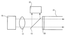
- FIG. 1 is an overall configuration diagram of a gas analyzer according to this embodiment.
- the sample gas contains two components of nitrogen monoxide gas (hereinafter simply referred to as NO gas) and nitrogen dioxide gas (hereinafter simply referred to as NO 2 gas), but sulfur dioxide gas (hereinafter simply referred to as SO 2 gas). Shall not be included.
- the gas analyzer analyzes these NO gas and NO 2 gas.
- a thick solid arrow indicates a gas flow path
- a dotted arrow indicates a light path
- a thin solid arrow indicates an electrical signal path.
- the gas analyzer 100 includes an NO 2 gas absorbing light emitting unit 11, an O 3 gas absorbing light emitting unit 12, a partial reflecting unit 13, a gas flow cell 21, a transmitted light receiving unit 31, and a reference light receiving unit.
- Unit 32 gas adjustment unit 41, gas suction unit 51, and signal processing / drive control unit 61.
- the NO 2 gas absorption light emitting unit 11 is a light emitting unit that emits NO 2 gas absorption irradiation light having a wavelength at which NO 2 gas absorbs and a wavelength at which O 3 gas does not absorb.
- a light emitting diode (LED) of irradiation light having a central emission wavelength in a wavelength range of 350 nm to 500 nm in a region extending from ultraviolet light to visible light. As shown in FIG. 2, only NO 2 gas absorbs light in this wavelength region.
- O 3 light-emitting unit 12 for gas absorption is a light-emitting unit that O 3 gas emits O 3 gas absorption for the irradiation light of a wavelength absorption.
- O 3 gas emits O 3 gas absorption for the irradiation light of a wavelength absorption.
- a light emitting diode (LED) for irradiation light having a central emission wavelength in the wavelength range of 240 nm to 330 nm in the ultraviolet region can be selected.
- LED light emitting diode
- NO 2 gas absorbs in this wavelength region. It is not taken into account because no SO 2 gas is present.
- the partial reflection unit 13 is a half mirror, and has a predetermined transmittance for irradiation light for absorbing NO 2 gas and irradiation light for absorbing O 3 gas (hereinafter simply referred to as irradiation light for absorbing light for absorbing NO 2 gas and for absorbing O 3 gas). Both the irradiation light and the irradiation light for NO 2 gas absorption and the irradiation light for O 3 gas absorption are not output at the same time, for example, each is output separately by time). Further, the irradiation light is reflected at a predetermined reflectance.
- Irradiation light emitted from the NO 2 gas absorption light-emitting unit 11 and the O 3 gas absorption light-emitting unit 12 is incident on the partial reflection unit 13.
- the partial reflection unit 13 a part of the irradiation light is reflected and the rest of the irradiation light is transmitted.
- the irradiation light reflected by the partial reflection unit 13 enters the reference light receiving unit 32. Further, the irradiation light transmitted through the partial reflection portion 13 is incident on the gas flow cell 21.
- the gas distribution cell 21 further includes a tube 22, light transmission windows 23 and 24, a detection space 25, a gas inlet 26, and a gas outlet 27.
- the tube 22 is a cylinder.
- the inner surface of the tube 22 can be, for example, a polished stainless steel inner surface. Thereby, the reflectance of irradiation light can be kept favorable, preventing adsorption of measurement object gas. In the tube 22, the irradiation light propagates while being reflected by the inner surface of the tube 22.
- the light transmission window 23 and the light transmission window 24 are made of a material exhibiting light transmittance in the emission wavelength region of the irradiation light emitted from the NO 2 gas absorption light emitting portion 11 and the O 3 gas absorption light emission portion 12.
- synthetic quartz or calcium fluoride can be used as the material.
- the detection space 25 is a closed space defined by the tube 22, the light transmission window 23, and the light transmission window 24.
- the gas inlet 26 and the gas outlet 27 communicate with the detection space 25.
- the measurement target gas flows into the detection space 25 from the gas inlet 26 and flows out of the gas outlet 27.
- irradiation light is irradiated to the flowing measurement target gas, and light absorption occurs.
- the transmitted light receiving unit 31 receives the irradiation light transmitted through the gas flow cell 21 and outputs a detection signal corresponding to the light intensity.
- the transmitted light receiving unit 31 includes a photodiode or a photomultiplier tube having sensitivity to the emission wavelength of irradiation light emitted from the NO 2 gas absorption light emitting unit 11 and the O 3 gas absorption light emitting unit 12. You can choose. For example, a silicon photodiode can be selected.
- Such a transmitted light receiving unit 31 has a function of detecting light absorption by the measurement target gas. That is, compared with the case where there is no light absorption due to the measurement target gas, the light intensity of the irradiation light received by the transmitted light receiving unit 31 decreases when there is light absorption.
- the gas concentration is measured using the correlation.
- the irradiation light transmitted through the partial reflection portion 13 passes through the light-transmitting light transmission window 23 constituting one end of the gas flow cell 21, propagates through the detection space 25 inside the tube 22, and constitutes the other end.
- the light is transmitted through the light transmissive window 24 and enters the transmitted light receiving unit 31.
- the reference light receiving unit 32 is provided to receive the irradiation light reflected by the partial reflection unit 13.
- the reference light receiving unit 32 includes a photodiode, a photomultiplier tube, or the like that is sensitive to the emission wavelength of the irradiation light emitted from the NO 2 gas absorption light emitting unit 11 and the O 3 gas absorption light emitting unit 12. You can choose. For example, a silicon photodiode can be selected.
- the reference light receiving unit 32 has a function of detecting fluctuations in irradiation light emitted from the NO 2 gas absorbing light emitting unit 11 and the O 3 gas absorbing light emitting unit 12.
- the irradiation light varies, the light intensity of the irradiation light received by the reference light receiving unit 32 varies.
- the gas concentration is corrected using the fluctuation amount of the light intensity.
- the gas adjustment unit 41 further includes an ozone generation unit 42 and a gas mixing unit 43.
- the ozone generator 42 has a function of generating ozone gas. Atmosphere containing oxygen to the ozone generator 42, instrument air, or the raw material gas G O such as oxygen gas (O 2 gas) flows. The operation of the ozone generator 42 is controlled by a signal processing / drive controller 61. In operation of the ozone generator 42, ozone generator 42, by electrical means, such as silent discharge, using an O 2 gas of the raw material gas G O generates O 3 gas, sufficiently containing the O 3 gas The source gas GO is caused to flow out. In an off-state, the ozone generator 42 is directly passing the raw material gas G O without generating the O 3 gas. In this way, the signal processing / drive control unit 61 controls the operation / non-operation of the ozone generation unit 42.
- the signal processing / drive control unit 61 controls the operation / non-operation of the ozone generation unit 42.
- Gas mixing unit 43 at the time the raw material gas G O (operation from the sample gas G S and ozone generator 42 is a raw material gas G O containing O 3 gas in large quantities, also in an off-state free of O 3 gas is provided to mix the free feed gas is G O).
- the gas mixing unit 43 causes the gas mixing unit 43 to directly flow out as a measurement target gas.
- the measurement target gas flowing out from the gas mixing unit 43 flows through the detection space 25 in the gas flow cell 21 from the gas inlet 26 and flows out from the gas outlet 27.
- the gas suction unit 51 has a function of sucking gas.
- the measurement target gas from the gas mixing unit 43 is drawn into the detection space 25 by exhausting the detection space 25 of the gas flow cell 21.
- the gas suction part 51 can also be provided between the gas mixing part 43 and the gas inlet 26.
- the signal processing / drive control unit 61 has a function of supplying a driving current necessary for causing the NO 2 gas absorption light emitting unit 11 and the O 3 gas absorption light emitting unit 12 to emit light. Further, the signal processing / drive control unit 61 has a received light signal processing function for calculating the gas concentration based on the received light signals from the transmitted light receiving unit 31 and the reference light receiving unit 32. Further, the signal processing / drive control unit 61 has a control function for switching operation / non-operation of the ozone generation unit 42.
- the configuration of the gas analyzer 100 is as described above.
- the principle of measurement is an absorption method based on the following Lambert-Beer law.
- P 1 is the output intensity of the transmitted light that has passed through the measurement target gas flowing in the detection space 25
- P 0 is the output intensity of the reference light before passing through the measurement target gas
- ⁇ is the molar extinction coefficient
- c is The gas concentration, L, represents the optical path length.
- the molar extinction coefficient ⁇ is uniquely determined by determining the type of gas and the wavelength of the light source, and since the optical path length L is constant, the ratio between the output intensities P 1 and P 0 is an exponential function of the gas concentration c.
- the output intensities P 1 and P 0 are measured, and the gas concentration is detected by the above equation ( 1).
- the gas analyzer 100 emits irradiation light that is either NO 2 gas absorption irradiation light or O 3 gas absorption irradiation light.
- a part of the irradiation light at this time is reflected by the partial reflection unit 13 with a known constant reflectance and is incident on the reference light receiving unit 32.
- the output intensity P 0 by the reference light can be obtained from the signal of the reference light receiving unit 32.
- a part of the irradiation light is transmitted through the partial reflection unit 13 with a known constant transmittance, propagates through the detection space 25 through the light transmission window 23, and is transmitted through the light transmission window 24 after being absorbed. The light enters the light receiving unit 31.
- the output intensity P 1 by the transmitted light can be obtained from the signal of the transmitted light receiving unit 31. Therefore, the gas concentration c can be obtained from the ratio between the output intensities P 1 and P 0 .
- This principle can be applied to both the analysis using the irradiation light for absorbing NO 2 gas and the analysis using the irradiation light for absorbing O 3 gas. The detection principle is like this.
- the transmitted light receiving unit 31 and the reference light receiving unit 32 are commonly used when measuring the NO 2 gas concentration and the O 3 gas concentration. Therefore, if the NO 2 gas absorption light-emitting unit 11 and the O 3 gas absorption light-emitting unit 12 emit light at the same time, the light reception signal becomes the sum of the two and cannot be separated.
- the signal processing / drive control unit 61 controls the NO 2 gas absorption light-emitting unit 11 and the O 3 gas absorption light-emitting unit 12 to alternately emit light without simultaneously emitting light. Further, the measurement and processing of the received light signal are also performed in synchronization with the light emission period, thereby separating the signals. Measurement by absorption is like this.
- Such measurement is performed when the ozone generation unit 42 is in an operating state and the gas adjustment unit 41 is in an oxidized output, and when the ozone generation unit 42 is in a non-operational state and the gas adjustment unit 41 is in a normal output.
- a gas analyzer 100 is (A) Analysis with irradiation light for absorbing NO 2 gas at the time of oxidation output, (B) Analysis by irradiation light for absorbing O 3 gas at the time of oxidation output, (C) Analysis with irradiation light for absorbing NO 2 gas at normal output, (D) Normal analysis by the O 3 gas absorption for the irradiation light at the time of output, Four types of analysis are possible.
- the ozone generator 42 is in an operating state. At this time, the ozone generating unit 42 generates ozone gas (hereinafter simply referred to as O 3 gas) from O 2 gas contained in the source gas G 0 such as the atmosphere, instrument air, or oxygen gas. Although the generation amount of O 3 gas can be determined as appropriate, it is supplied in excess of at least the maximum amount in the measured concentration range of NO gas. From the ozone generator 42 to the gas mixing unit 43 supplies the raw material gas G O containing O 3 gas sufficiently.
- O 3 gas ozone gas
- O 3 gas amount supplied from the ozone generator 42 is, because it is excessive relative to NO gas amount in the sample gas G S, NO gas in the sample gas G S is according to the chemical reaction formula (1), All are converted to NO 2 gas.
- the gas mixing unit 43 and converted all NO gas in the sample gas G S is the NO 2 gas.
- some of the NO 2 gas in the sample gas G S, and, in some NO 2 gas produced by a chemical reaction formula (1) is converted to N 2 O 5 gas. Therefore, the amount of gas NO 2 gas, and NO 2 gas in the gas amount produced from NO in the sample gas G S, the sum of the amount of gas NO 2 gas in the sample gas G S, further N 2 O 5 The amount of gas is reduced by twice the amount of gas. This is because the amount of N 2 O 5 gas after the reaction is half of the amount of NO 2 gas according to the chemical reaction formula (2). Furthermore, a part of the surplus O 3 gas remains.
- the gas conditioning unit 41 as performs oxidation output for outputting a NO gas contained in the sample gas G S as a measurement object gas reacted to all oxidized NO 2 gas by the O 3 gas.
- a NO gas contained in the sample gas G S as a measurement object gas reacted to all oxidized NO 2 gas by the O 3 gas.
- NO 2 gas, N 2 O 5 gas, excess O 3 gas, the measurement object gas containing the raw material gas G O and excess sample gas G S excess is introduced into the gas flow cell 21.
- NO 2 irradiation light gas absorption incident on the detection space 25 of the passes through the partial reflection unit 13 light transmissive window 23 via a gas flow cell 21, while propagating the detection space 25, absorption by NO 2 gas Is done.
- Such absorbed light for absorbing NO 2 gas passes through the light transmission window 24 and enters the transmitted light receiving unit 31. Therefore, the output intensity P 1 can be obtained from the signal of the transmitted light receiving unit 31.
- the transmitted light receiving unit 31 and the reference light receiving unit 32 as the light receiving elements in this way, not only can the concentration be measured, but also the output of the NO 2 gas absorbing light emitting unit 11 varies due to various factors. Also, there is an effect that an error in density measurement can be reduced by calculating the ratio of the two received light signals.
- Output signals from the transmitted light receiving unit 31 and the reference light receiving unit 32 are transmitted to the signal processing / drive control unit 61.
- the signal processing / drive control unit 61 calculates the NO 2 gas concentration in the detection space 25 of the gas flow cell 21 based on the above mathematical formula 1. Since the raw material gas G O for producing O 3 gas is mixed in the gas mixing unit 43, NO 2 gas concentration is diluted in accordance with the flow mixing ratio of the raw material gas G O and the sample gas G S Yes. Therefore, by multiplying the flow mixing ratio of a gas mixing section 43, calculates the NO 2 gas concentration c m contained in the sample gas G S.
- the O 3 gas absorption light emitting unit 12 emits light. Irradiation light for absorbing O 3 gas from the light emitting unit 12 for absorbing O 3 gas is reflected by the partial reflection unit 13 with a known constant reflectance and enters the reference light receiving unit 32. Therefore, the output intensity P 0 can be obtained from the signal from the reference light receiving unit 32.
- the irradiation light for absorbing O 3 gas that has passed through the partial reflection portion 13 and entered the detection space 25 in the gas flow cell 21 through the light transmission window 23 propagates through the detection space 25, while O 3 gas and NO. Absorbed by two gases.
- Such absorbed light for absorbing O 3 gas is transmitted through the light transmission window 24 and enters the transmitted light receiving unit 31. Therefore, it is possible to determine the output intensity P 1 from the signal of the transmitted light receiving unit 31.
- the output intensity P 1 includes light absorption by NO 2 gas.
- the transmitted light receiving unit 31 and the reference light receiving unit 32 as the light receiving elements in this way, not only can the concentration be measured, but the output of the light emitting unit 12 for absorbing O 3 gas varies due to various factors. Also, there is an effect that an error in density measurement can be reduced by calculating the ratio of the two received light signals.
- Output signals from the transmitted light receiving unit 31 and the reference light receiving unit 32 are transmitted to the signal processing / drive control unit 61.
- the signal processing / drive control unit 61 calculates the output intensities P 0 and P 1 , calculates the O 3 gas concentration + NO 2 gas concentration based on Equation 1, and multiplies the flow rate mixing ratio in the gas mixing unit 43. by, O 3 calculates the gas concentration c 3 + NO 2 gas concentration c m contained in the sample gas G S.
- the measurement is performed after the ozone generating unit 42 is in an inoperative state and the gas adjusting unit 41 is normally output.
- the ozone generator 42 is in an inoperative state. At this time, the raw material gas G O is passes through the ozone generator 42 as described above, is mixed with the sample gas G S in the gas mixing portion 43. O 3 never since the gas is not present chemical reaction occurs, and the raw material gas G O and the sample gas G S-free reaction as it flows out from the gas mixing unit 43. Gas conditioning unit 41 performs a normal output that outputs the sample gas G S and the raw material gas G O unresponsive as a measurement target gas.
- the detection of the gas concentration itself is obtained in the same manner as the operation of the ozone generator 42 described above (during oxidation output). In this way, the NO 2 gas concentration c 2 is calculated.
- the NO 2 gas concentration c m oxidation output state, of the measurement target gas, from the sum of the sample gas G of the original that was included in the S NO gas concentration c 1 and the original NO 2 gas concentration c 2 The concentration obtained by subtracting twice the N 2 O 5 gas concentration. This is because the production of N 2 O 5 requires two NO 2 .
- the N 2 O 5 gas concentration is 1 ⁇ 2 of the concentration obtained by subtracting the NO 2 gas concentration cm from the sum of the original NO gas concentration c 1 and the original NO 2 gas concentration c 2 .
- the O 3 gas concentration supplied by the ozone generator 42 can be known in advance by an ozone meter or the like built in the ozone generator 42, and the value is c 0 .
- the O 3 gas consumed by the reaction is used for a reaction from NO gas to NO 2 gas, and further used for a reaction from NO 2 gas to N 2 O 5 gas. Therefore, the following equation is obtained.
- the NO gas concentration c 1 is expressed by the following equation.
- the NO gas concentration c 1 and the NO 2 gas concentration c 2 can be measured.
- the gas concentrations of NO gas and NO 2 can be measured.
- zero gas G ZERO or span gas G SPAN can be used for gas concentration calibration.
- the zero gas G ZERO is a gas in which the NO 2 gas absorption light emitting unit 11 and the O 3 gas absorption light emitting unit 12 do not absorb light, for example, nitrogen gas (N 2 gas).
- Span gas G SPAN is a gas that has been calibrated at a maximum concentration value of the desired measurement range, such as NO gas, NO 2 gas is used.
- Stopping the supply of the sample gas G S, followed by performing the supply of the zero gas G ZERO calibrated by measuring the light signal at the zero gas G ZERO distribution, or at the time span G SPAN flow by performing the supply of the span gas G SPAN Calibration can be performed by measuring the absorbed light-receiving signal. Although this calibration can be performed at any time, it is performed when it is assumed that the gas concentration indicating value fluctuates due to aging of the component parts, and an accurate value is indicated.
- the gas analyzer 100 is like this.
- the configuration as a gas analyzer is the same as that of the first embodiment described with reference to FIG. 1, but the analysis object is different.
- the NO gas concentration c 1 and the NO 2 gas concentration c 2 are calculated, but the SO 2 gas concentration c S is measured simultaneously with the above measurement.
- the sample gas contains NO gas, NO 2 gas, and SO 2 gas, and these NO gas concentration c 1 , NO 2 gas concentration c 2 , and SO 2 gas concentration c S are measured.
- UV absorption spectrum of the SO 2 gas is near 270 nm ⁇ 310 nm, as shown in FIG. 2, overlaps the ultraviolet absorption spectrum of the O 3 gas.
- the central wavelength of the O 3 gas light-absorbing light emitting portion 12 is around 280 nm, an SO 2 gas absorption signal can be obtained.
- Such measurement is performed when the ozone generation unit 42 is in an operating state and the gas adjustment unit 41 is in an oxidized output, and when the ozone generation unit 42 is in a non-operational state and the gas adjustment unit 41 is in a normal output. Is called.
- such a gas analyzer 100 is (A) Analysis with irradiation light for absorbing NO 2 gas at the time of oxidation output, (B) analysis by the O 3 gas absorption for the irradiation light at the time of oxidation output, (C) Analysis with irradiation light for absorbing NO 2 gas at normal output, (D) Analysis with irradiation light for absorbing O 3 gas at normal output,
- A Analysis with irradiation light for absorbing NO 2 gas at the time of oxidation output
- B analysis by the O 3 gas absorption for the irradiation light at the time of oxidation output
- C Analysis with irradiation light for absorbing NO 2 gas at normal output
- D Analysis with irradiation light for absorbing O 3 gas at normal output
- the following four types of analysis are possible: (a), (b), (c), and (d) are all analyzed, and the gas concentration is calculated using the measured values obtained by these.
- the ozone generator 42 is in an operating state.
- Gas conditioning unit 41 as described above this time, an oxidation output for outputting a NO gas contained in the sample gas G S as a measurement object gas reacted to all oxidized NO 2 gas by the O 3 gas.
- the SO 2 gas and the O 3 gas do not cause a chemical reaction.
- Such as these SO 2 gas, NO 2 gas is introduced into the N 2 O 5 gas, excess O 3 gas, the excess of the raw material gas G O and excess sample gas G S measurement target gas is gas flow cell 21 comprising The
- NO 2 gas concentration cm of the gas analyzer 100 is calculated.
- NO 2 gas concentration measurement emits light only NO 2 gas absorption for the light emitting unit 11.
- NO 2 irradiation light gas absorption from NO 2 gas absorption for the light emitting unit 11 is reflected by the known constant reflectivity by the partial reflection unit 13 and enters the reference light receiving unit 32. Therefore, the output intensity P 0 can be obtained from the signal from the reference light receiving unit 32.
- NO 2 irradiation light gas absorption incident on the detection space 25 of the passes through the partial reflection unit 13 light transmissive window 23 via a gas flow cell 21, while propagating the detection space 25, absorption by NO 2 gas Is done.
- Such absorbed light for absorbing NO 2 gas passes through the light transmission window 24 and enters the transmitted light receiving unit 31. Therefore, the output intensity P 1 can be obtained from the signal of the transmitted light receiving unit 31.
- Output signals from the transmitted light receiving unit 31 and the reference light receiving unit 32 are transmitted to the signal processing / drive control unit 61.
- the signal processing / drive control unit 61 calculates the NO 2 gas concentration in the detection space 25 of the gas flow cell 21 based on the above mathematical formula 1. Since the raw material gas G O for producing O 3 gas is mixed in the gas mixing unit 43, NO 2 gas concentration is diluted in accordance with the flow mixing ratio of the raw material gas G O and the sample gas G S Yes. Therefore, by multiplying the flow mixing ratio of a gas mixing section 43, calculates the NO 2 gas concentration c m contained in the sample gas G S.
- the O 3 gas absorption light emitting unit 12 emits light. Irradiation light for absorbing O 3 gas from the light emitting unit 12 for absorbing O 3 gas is reflected by the partial reflection unit 13 with a known constant reflectance and enters the reference light receiving unit 32. Therefore, the output intensity P 0 can be obtained from the signal from the reference light receiving unit 32.
- O 3 irradiation light gas absorption incident on the detection space 25 in the gas flow cell 21 passes through the partial reflection unit 13 through the light transmission window 23, while propagating the detection space 25, SO 2 gas, O Absorbed by 3 gas and NO 2 gas.
- Such absorbed light for absorbing O 3 gas is transmitted through the light transmission window 24 and enters the transmitted light receiving unit 31. Therefore, the output intensity P 1 can be obtained from the signal of the transmitted light receiving unit 31.
- the output intensity P 1 includes light absorption by SO 2 gas, O 3 gas and NO 2 gas.
- Output signals from the transmitted light receiving unit 31 and the reference light receiving unit 32 are transmitted to the signal processing / drive control unit 61.
- the signal processing / drive control unit 61 calculates the output intensities P 0 and P 1 , calculates the O 3 gas concentration + SO 2 gas concentration + NO 2 gas concentration based on Equation 1, and further mixes the flow rate in the gas mixing unit 43. by multiplying the ratio to calculate the sample gas G O 3 gas concentration is being included in the S c 3 + SO 2 gas concentration c S + NO 2 gas concentration c m.
- the measurement is performed after the ozone generating unit 42 is in an inoperative state and the gas adjusting unit 41 is normally output.
- the ozone generator 42 is in an inoperative state.
- This state gas contained in the sample gas G S that circulates in the gas flow cell 21, NO gas contained in the sample gas G S, NO 2 gas, SO 2 gas has become all intact state.
- the raw material gas G O are mixed in the gas mixing portion 43, the concentration of NO gas, NO 2 gas, SO 2 gas is diluted in accordance with the flow mixing ratio of the raw material gas G O and the sample gas G S ing. And such feed gas G O and the sample gas G S is introduced into the gas flow cell 21.
- the gas concentration detection itself is obtained in the same manner as the operation of the ozone generator 42 described above (at the time of oxidation output), and the NO 2 gas concentration is calculated. Further, by multiplying the flow mixing ratio of a gas mixing section 43, it calculates the NO 2 gas concentration c 2 contained in the sample gas G S.
- the measurement is performed after the ozone generating unit 42 is in an inoperative state and the gas adjusting unit 41 is normally output. At this time, obtaining the SO 2 gas concentration c S + NO 2 gas concentration c 2 in the sample gas G S. This is the analysis by the above (d) irradiation light for absorbing O 3 gas at normal output.
- the ozone generator 42 is in an inoperative state.
- This state gas contained in the sample gas G S that circulates in the gas flow cell 21, NO gas contained in the sample gas G S, NO 2 gas, SO 2 gas has become all intact state.
- the raw material gas G O are mixed in the gas mixing portion 43, the concentration of NO gas, NO 2 gas, SO 2 gas is diluted in accordance with the flow mixing ratio of the raw material gas G O and the sample gas G S ing. And such feed gas G O and the sample gas G S is introduced into the gas flow cell 21.
- the gas concentration detection itself is obtained in the same manner as described above, and the SO 2 gas concentration + NO 2 gas concentration is calculated. Further, by multiplying the flow mixing ratio of a gas mixing section 43, and calculates the SO 2 gas concentration c S + NO 2 gas concentration c 2 contained in the sample gas G S.
- the SO 2 gas concentration c S is determined.
- the O 3 gas concentration c 3 is determined.
- the NO gas concentration c 1 is also expressed by the above [Equation 5].
- the NO gas concentration c 1 , the NO 2 gas concentration c 2 , and the SO 2 gas concentration c S can be measured.
- the gas concentrations of NO gas, NO 2 gas, and SO 2 gas can be measured.
- zero gas G ZERO or span gas G SPAN can be used for gas concentration calibration.
- Zero gas G ZERO is a gas, for example, nitrogen gas, in which the NO 2 gas absorption light-emitting unit 11 and the O 3 gas absorption light-emitting unit 12 do not absorb light.
- the span gas G SPAN is a gas calibrated with the maximum concentration value of a desired measurement range, and for example, NO, NO 2 , SO 2 gas is used.
- Stopping the supply of the sample gas G S, followed by performing the supply of the zero gas G ZERO calibrated by measuring the light signal at the zero gas G ZERO distribution, or at the time span G SPAN flow by performing the supply of the span gas G SPAN Calibration can be performed by measuring the absorbed light-receiving signal. Although this calibration can be performed at any time, it is performed when it is assumed that the gas concentration indicating value fluctuates due to aging of the component parts, and an accurate value is indicated.
- the gas analyzer 100 is like this.
- the gas analyzer 100 performs the analysis in this way. According to the present invention, the gas concentrations of NO gas, NO 2 gas, and SO 2 gas can be accurately measured with a simple configuration.
- the gas analyzer 200 includes a light emitting unit 11 for absorbing NO 2 gas, a light emitting unit 12 for absorbing O 3 gas, a partial reflecting unit 13, a gas flow cell 21, a transmitted light receiving unit 31, and a reference light receiving unit.
- Unit 32 gas adjustment unit 41, gas suction unit 51, signal processing / drive control unit 61, and correction unit 71.
- correction unit 71 is added.
- the correction unit 71 and its operation will be described with emphasis, and the other components will be assigned the same numbers and redundant description will be omitted.
- the correction unit 71 is connected to the reference light receiving unit 32, the signal processing / drive control unit 61, the NO 2 gas absorption light emitting unit 11, and the O 3 gas absorption light emitting unit 12. Based on this, it has a function of correcting the current for driving the NO 2 gas absorption light emitting unit 11 and the O 3 gas absorption light emitting unit 12.
- Reference-light receiving part 32 by receiving the reference light by NO 2 gas absorption for the irradiation light from the NO 2 gas absorption for the light emitting unit 11 and outputs the intensity signal. Based on the intensity signal, the correction unit 71 corrects and outputs the drive signal, which is a light emitting diode drive current, so that the output intensity is constant.
- the reference light receiving unit 32 by receiving the reference light by the O 3 gas absorption for the irradiation light from the O 3 gas absorption for the light emitting unit 12 and outputs the intensity signal. Based on the intensity signal, the correction unit 71 corrects and outputs the drive signal, which is a light emitting diode drive current, so that the output intensity is constant.
- a lens 14 is further provided on the optical axis of the NO 2 gas absorption light emitting unit 11, and O 3
- a lens 15 is provided on the optical axis of the gas absorption light emitting unit 12.
- NO 2 gas light-absorbing light-emitting unit 11 and the lens 14 may be integrally configured by modularization
- O 3 gas light-absorbing light-emitting unit 12 and the lens 15 may be integrally configured by modularization
- the light emitting portion 16 is arranged in place of NO 2 gas absorption for the light emitting portion 11 and the O 3 light-emitting unit 12 for gas absorption.
- the light emitting unit 16 is a light emitting diode array in which the NO 2 gas absorbing light emitting unit 11 and the O 3 gas absorbing light emitting unit 12 are integrated in close proximity.
- a lens 17 is disposed on the optical axis of the light emitting unit 11 for absorbing NO 2 gas and the light emitting unit 12 for absorbing O 3 gas.
- the optical axes of the NO 2 gas absorbing light emitting portion 11 and the O 3 gas absorbing light emitting portion 12 are close to each other, so that only one lens 17 for enhancing directivity is required. Further, since the optical axes are close to each other, the incident efficiency to the reference light receiving unit 32 is also improved. As a result, there is an effect that the signal intensity is increased, and consequently the accuracy and stability of the gas concentration measurement are improved.
- the lens 18 is further disposed between the light transmitting window 24 and the transmitted light receiving unit 31. It is arranged.
- the lens 18 collects the NO 2 gas absorption irradiation light and the O 3 gas absorption irradiation light transmitted through the light transmission window 24, and efficiently enters the transmitted light receiving unit 31. As a result, there is an effect that the signal intensity is increased, and consequently the accuracy and stability of the gas concentration measurement are improved.
- the light transmission window 24 and the lens 18 may be integrally configured by modularization.
- the light transmission window 24 itself may be a convex lens 18 that is light transmissive and has a light collecting effect, and the gas flow cell 21 may be configured by fixing the lens 18 to the tube 22.
- the light transmission window 24 of the gas flow cell 21 is replaced with a reflection part 28, and the transmitted light receiving part 31 is arranged at a position where the return light is reflected by the partial reflection part 13.
- forward light that is irradiation light emitted from the NO 2 gas absorption light emitting unit 11 and the O 3 gas absorption light emitting unit 12 passes through the light transmission window 23 and propagates in the detection space 25 of the tube 22. Then, the light is reflected by the reflecting portion 28 and becomes return path light. The reflected return light propagates in the detection space 25 of the tube 22 in the opposite direction, exits from the light transmission window 23, is reflected by the partial reflection unit 13, and enters the transmitted light receiving unit 31.
- the optical path length with light absorption by gas is doubled, so that the light absorption signal is improved and the gas concentration measurement accuracy is improved. And can improve the stability.
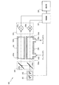
- FIG. 1 This is provided with a light emitting / receiving part 19 integrated by modularization while bringing the NO 2 gas absorbing light emitting part 11, the O 3 gas absorbing light emitting part 12 and the transmitted light receiving part 31 close to each other. Further, the light transmission window 24 of the gas flow cell 21 is replaced with the reflection portion 28, and the transmitted light receiving portion 31 is disposed at a position where the return light is transmitted by the partial reflection portion 13.
- the lens 17 condenses the irradiation light incident on the transmitted light receiving unit 31 and the function of increasing the directivity of the irradiation light from the NO 2 gas absorption light emitting unit 11 and the O 3 gas absorption light emitting unit 12. It will have the function to do. Further, since the optical path length with light absorption by gas is doubled, it is possible to expect the effect of improving the light absorption signal and improving the accuracy and stability of gas concentration measurement.
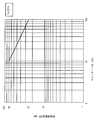
- FIG. 9 is a duty ratio-allowable current characteristic diagram of the light emitting diode. This embodiment further improves the measurement accuracy of the gas analyzers of the first, second, third, fourth, fifth, sixth, and seventh embodiments described above.
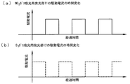
- the allowable current of the light emitting diode is characterized in that, generally, the smaller the duty ratio and the shorter the output period, the larger the current value can be secured. Therefore, the drive current of the NO 2 gas absorption light emitting unit 11 and the O 3 gas absorption light emitting unit 12 is changed from a large duty ratio as shown in FIG. 10 to a small duty ratio as shown in FIG. Shorter). At this time, the output time is shortened as shown in FIG. 11, but the drive current value can be increased. Therefore, the output intensity of the irradiation light can be increased to ensure a high signal level, the signal level against noise is relatively high, and a stable gas concentration value can be calculated.
- the light emission time of the light emitting diode 11 for absorbing NO 2 gas and the light emitting portion 12 for absorbing O 3 gas can be shortened, deterioration due to heat or the like is suppressed, and the lifetime is longer than that of continuous light emission. It becomes possible to keep for a long time.
- Such a gas analyzer of the present invention comprises two components of nitrogen monoxide gas (NO gas) and nitrogen dioxide gas (NO 2 ), or nitrogen monoxide gas (NO gas), nitrogen dioxide gas (NO 2 ) and It is good for analysis for measuring three components of sulfur dioxide gas (SO 2 ), and is optimal for measurement of combustion exhaust gas such as boiler and garbage incineration.
- NO gas nitrogen monoxide gas
- NO 2 nitrogen dioxide gas
- SO 2 sulfur dioxide gas
- gas analysis for steel blast furnace, converter, heat treatment furnace, sintering (pellet equipment), coke oven], fruit and vegetable storage and ripening, biochemistry (microorganism) [fermentation], air pollution [incinerator, flue gas desulfurization / Denitration], exhaust gas (removal tester) of internal combustion engines such as automobiles and ships, disaster prevention [explosive gas detection, toxic gas detection, new building material combustion gas analysis], plant growth, chemical analysis [oil refinery plant, petrochemical Plants, gas generation plants], environmental [landing concentration, concentration in tunnels, parking lots, building management], and analytical instruments for various physics and chemistry experiments.
Abstract
Description
吸光分析計300は、サンプルガスに含まれるNO2ガス(二酸化窒素ガス)濃度を紫外吸収法により測定する。吸光分析計300は、紫外光源301と、可視光源302と、リファレンスセル303と、サンプルセル304と、光案内機構305と、光検出部306と、制御部307と、演算部308と、を備えている。 For example,
The
このようにサンプルガスにNOガスおよびSO2ガスのガス成分が含まれている場合には、従来技術では、これらのNOガスおよびSO2ガスのガス成分の分析が困難であった。 Further, at the absorption wavelength of NO 2 gas in the visible wavelength region (wavelength of 400 nm or more), NO gas and SO 2 gas do not absorb, and visible transmitted light does not contain information about NO gas and SO 2 gas. Therefore, it is impossible to correct interference caused by NO gas or SO 2 gas, or to use it for concentration measurement of NO gas or SO 2 gas.
When the sample gas contains the gas components of NO gas and SO 2 gas as described above, it has been difficult to analyze the gas components of these NO gas and SO 2 gas in the prior art.
好ましくは、二酸化硫黄ガス(SO2ガス)、一酸化窒素ガス(NOガス)および二酸化窒素ガス(NO2ガス)の3成分のガス濃度を計測可能とするガス分析計を提供することにある。 Therefore, the present invention has been made to solve all of the above problems, and an object of the present invention is to provide at least nitrogen monoxide gas (NO gas) and nitrogen dioxide gas (NO 2 gas) contained in the sample gas with a simple configuration. It is to provide a gas analyzer that can measure the gas concentration of two components.
It is preferable to provide a gas analyzer capable of measuring the three component gas concentrations of sulfur dioxide gas (SO 2 gas), nitric oxide gas (NO gas) and nitrogen dioxide gas (NO 2 gas).
サンプルガスに含まれる一酸化窒素ガス(NOガス)および二酸化窒素ガス(NO2ガス)の2成分のガス濃度を測定するガス分析計であって、
サンプルガスに含まれる一酸化窒素ガス(NOガス)をオゾンの酸化により全て二酸化窒素ガス(NO2ガス)に反応させ、さらに二酸化窒素ガス(NO2ガス)の一部をオゾンの酸化により五酸化二窒素ガス(N2O5ガス)に反応させた測定対象ガスとして出力する酸化出力と、サンプルガスを無反応のまま測定対象ガスとして出力する通常出力と、を行うガス調整部と、
二酸化窒素ガス(NO2ガス)が吸光する紫外領域から可視領域までの波長のNO2ガス吸光用照射光を照射するNO2ガス吸光用発光部と、
オゾンガス(O3ガス)および二酸化窒素ガス(NO2ガス)が吸光する紫外領域の波長のO3ガス吸光用照射光を照射するO3ガス吸光用発光部と、
NO2ガス吸光用照射光およびO3ガス吸光用照射光の一部を反射し、残りを透過する部分反射部と、
ガス調整部からの測定対象ガスが流通する検出空間と、部分反射部を透過したNO2ガス吸光用照射光およびO3ガス吸光用照射光を検出空間へ入射させる光透過窓と、を有するガス流通セルと、
光透過窓を透過しガス流通セル内を伝播したNO2ガス吸光用照射光およびO3ガス吸光用照射光を受光する透過光受光部と、
部分反射部で反射したNO2ガス吸光用照射光およびO3ガス吸光用照射光を受光する基準光受光部と、
ガス調整部、NO2ガス吸光用発光部、O3ガス吸光用発光部、透過光受光部および基準光受光部と接続される信号処理・駆動制御部と、
を備え、
この信号処理・駆動制御部は、
ガス調整部を酸化出力状態に制御してNO2ガス吸光用照射光を発光したときの透過光受光部および基準光受光部からの信号を用いて、二酸化窒素ガス(NO2ガス)のガス濃度cmを算出し、
ガス調整部を酸化出力状態に制御してO3ガス吸光用照射光を発光したときの透過光受光部および基準光受光部からの信号を用いて、オゾンガス(O3ガス)のガス濃度c3を算出し、
ガス調整部を通常出力状態に制御してNO2ガス吸光用照射光を発光したときの透過光受光部および基準光受光部からの信号を用いて、二酸化窒素ガス(NO2ガス)のガス濃度c2を算出し、
供給されるオゾンガス(O3ガス)のガス濃度c0から、測定されたオゾンガス(O3ガス)のガス濃度c3を、減じて算出された反応消費時のガス濃度が、測定対象ガス中の一酸化窒素ガス(NOガス)のガス濃度c1に五酸化二窒素ガス(N2O5ガス)のガス濃度(c1+c2-cm)/2を加えたガス濃度に等しいことに基づいて、算出されたc0、cm、c3、c2、から一酸化窒素ガス(NOガス)のガス濃度c1を算出するようなガス分析計とした。 The present invention
A gas analyzer that measures the gas concentrations of two components of nitrogen monoxide gas (NO gas) and nitrogen dioxide gas (NO 2 gas) contained in a sample gas,
All nitric oxide gas contained in the sample gas (NO gas) by oxidation of ozone reacted in a nitrogen dioxide gas (NO 2 gas), further pentoxide a portion of the nitrogen dioxide gas (NO 2 gas) by oxidation of ozone A gas adjustment unit that performs an oxidation output that is output as a measurement target gas reacted with dinitrogen gas (N 2 O 5 gas), and a normal output that is output as a measurement target gas without any reaction;
A light emitting part for absorbing NO 2 gas that irradiates irradiation light for absorbing NO 2 gas having a wavelength from an ultraviolet region to a visible region in which nitrogen dioxide gas (NO 2 gas) absorbs;
A light emitting part for absorbing O 3 gas that irradiates irradiation light for absorbing O 3 gas having a wavelength in the ultraviolet region where ozone gas (O 3 gas) and nitrogen dioxide gas (NO 2 gas) absorb;
A partially reflecting portion that reflects part of the irradiation light for NO 2 gas absorption and part of the irradiation light for O 3 gas absorption and transmits the rest;
Gas having a detection space which the measurement target gas from the gas conditioning unit flows, and the light transmission window for entering the partial reflection region permeated NO 2 gas absorption irradiation light and the O 3 irradiation light gas absorption into the detection space, the A distribution cell;
A transmitted light receiving unit that receives the irradiation light for absorbing NO 2 gas and the irradiation light for absorbing O 3 gas transmitted through the light transmission window and propagated in the gas flow cell;
A reference light receiving unit that receives the irradiation light for absorbing NO 2 gas and the irradiation light for absorbing O 3 gas reflected by the partial reflection unit;
A signal processing / drive control unit connected to the gas adjusting unit, the NO 2 gas absorbing light emitting unit, the O 3 gas absorbing light emitting unit, the transmitted light receiving unit, and the reference light receiving unit;
With
This signal processing / drive control unit
The gas concentration of the nitrogen dioxide gas (NO 2 gas) is controlled by using the signals from the transmitted light receiving unit and the reference light receiving unit when the gas adjusting unit is controlled to the oxidation output state and the irradiation light for NO 2 gas absorption is emitted. c m is calculated,
The gas conditioning unit by using a signal from the transmitted light receiving unit and the reference light receiving unit when the emitting O 3 irradiation light gas absorption by controlling the oxidation output state, gas concentration c 3 of ozone (O 3 gas) To calculate
The gas concentration of the nitrogen dioxide gas (NO 2 gas) is controlled using signals from the transmitted light receiving unit and the reference light receiving unit when the gas adjusting unit is controlled to the normal output state and the irradiation light for NO 2 gas absorption is emitted. c 2 is calculated,
From the gas concentration c 0 of the ozone gas (O 3 gas) supplied, the gas concentration c 3 of the measured ozone (O 3 gas), the gas concentration in the reaction consumption calculated by subtracting the, in the gas as the object of measurement based on the equal to the gas concentration (c 1 + c 2 -c m ) / 2 gas concentration by adding gas concentration c 1 to
サンプルガスに含まれる一酸化窒素ガス(NOガス)、二酸化窒素ガス(NO2)および二酸化硫黄ガス(SO2ガス)の3成分のガス濃度を測定するガス分析計であって、
サンプルガスに含まれる一酸化窒素ガス(NOガス)をオゾンの酸化により全て二酸化窒素ガス(NO2ガス)に反応させ、さらに二酸化窒素ガス(NO2ガス)の一部をオゾンの酸化により五酸化二窒素ガス(N2O5ガス)に反応させた測定対象ガスとして出力する酸化出力と、サンプルガスを無反応のまま測定対象ガスとして出力する通常出力と、を行うガス調整部と、
二酸化窒素ガス(NO2ガス)が吸光する紫外領域から可視領域までの波長のNO2ガス吸光用照射光を照射するNO2ガス吸光用発光部と、
オゾンガス(O3ガス)、二酸化硫黄ガス(SO2ガス)および二酸化窒素ガス(NO2ガス)が吸光する紫外領域の波長のO3ガス吸光用照射光を照射するO3ガス吸光用発光部と、
NO2ガス吸光用照射光およびO3ガス吸光用照射光の一部を反射し、残りを透過する部分反射部と、
ガス調整部からの測定対象ガスが流通する検出空間と、部分反射部を透過したNO2ガス吸光用照射光およびO3ガス吸光用照射光を検出空間へ入射させる光透過窓と、を有するガス流通セルと、
光透過窓を透過しガス流通セル内を伝播したNO2ガス吸光用照射光およびO3ガス吸光用照射光を受光する透過光受光部と、
部分反射部で反射したNO2ガス吸光用照射光およびO3ガス吸光用照射光を受光する基準光受光部と、
ガス調整部、NO2ガス吸光用発光部、O3ガス吸光用発光部、透過光受光部および基準光受光部と接続される信号処理・駆動制御部と、
を備え、
この信号処理・駆動制御部は、
ガス調整部を酸化出力状態に制御してNO2ガス吸光用照射光を発光したときの透過光受光部および基準光受光部からの信号を用いて、二酸化窒素ガス(NO2ガス)のガス濃度cmを算出し、
ガス調整部を酸化出力状態に制御してO3ガス吸光用照射光を発光したときの透過光受光部および基準光受光部からの信号を用いて、オゾンガス(O3ガス)のガス濃度c3および二酸化硫黄ガス(SO2ガス)のガス濃度csを算出し、
ガス調整部を通常出力状態に制御してNO2ガス吸光用照射光を発光したときの透過光受光部および基準光受光部からの信号を用いて、二酸化窒素ガス(NO2ガス)のガス濃度c2を算出し、
ガス調整部を通常出力状態に制御してO3ガス吸光用照射光を発光したときの透過光受光部および基準光受光部からの信号を用いて、二酸化硫黄ガス(SO2ガス)のガス濃度csを算出し、
供給されるオゾンガス(O3ガス)のガス濃度c0から、測定されたオゾンガス(O3ガス)のガス濃度c3を、減じて算出された反応消費時のガス濃度が、測定対象ガス中の一酸化窒素ガス(NOガス)のガス濃度c1に五酸化二窒素ガス(N2O5ガス)のガス濃度(c1+c2-cm)/2を加えたガス濃度に等しいことに基づいて、算出されたc0、cm、c3、c2、から一酸化窒素ガス(NOガス)のガス濃度c1を算出するようなガス分析計とした。 The present invention also provides:
A gas analyzer that measures the concentration of three components of nitrogen monoxide gas (NO gas), nitrogen dioxide gas (NO 2 ), and sulfur dioxide gas (SO 2 gas) contained in a sample gas,
All nitric oxide gas contained in the sample gas (NO gas) by oxidation of ozone reacted in a nitrogen dioxide gas (NO 2 gas), further pentoxide a portion of the nitrogen dioxide gas (NO 2 gas) by oxidation of ozone A gas adjustment unit that performs an oxidation output that is output as a measurement target gas reacted with dinitrogen gas (N 2 O 5 gas), and a normal output that is output as a measurement target gas without any reaction;
A light emitting part for absorbing NO 2 gas that irradiates irradiation light for absorbing NO 2 gas having a wavelength from an ultraviolet region to a visible region in which nitrogen dioxide gas (NO 2 gas) absorbs;
A light emitting part for absorbing O 3 gas that irradiates light for absorbing O 3 gas having a wavelength in the ultraviolet region where ozone gas (O 3 gas), sulfur dioxide gas (SO 2 gas) and nitrogen dioxide gas (NO 2 gas) absorb; ,
A partially reflecting portion that reflects part of the irradiation light for NO 2 gas absorption and part of the irradiation light for O 3 gas absorption and transmits the rest;
A gas having a detection space in which a measurement target gas from the gas adjustment unit flows, and a light transmission window through which the irradiation light for NO 2 gas absorption and the irradiation light for O 3 gas absorption transmitted through the partial reflection unit enter the detection space A distribution cell;
A transmitted light receiving unit that receives the irradiation light for absorbing NO 2 gas and the irradiation light for absorbing O 3 gas transmitted through the light transmission window and propagated in the gas flow cell;
A reference light receiving unit for receiving the reflected NO 2 irradiated light and gas absorption O 3 irradiation light gas absorption by the partially reflecting portion,
A signal processing / drive control unit connected to the gas adjusting unit, the NO 2 gas absorbing light emitting unit, the O 3 gas absorbing light emitting unit, the transmitted light receiving unit, and the reference light receiving unit;
With
This signal processing / drive control unit
The gas concentration of the nitrogen dioxide gas (NO 2 gas) is controlled by using the signals from the transmitted light receiving unit and the reference light receiving unit when the gas adjusting unit is controlled to the oxidation output state and the irradiation light for NO 2 gas absorption is emitted. c m is calculated,
The gas conditioning unit by using a signal from the transmitted light receiving unit and the reference light receiving unit when the emitting O 3 irradiation light gas absorption by controlling the oxidation output state, gas concentration c 3 of ozone (O 3 gas) And the gas concentration c s of sulfur dioxide gas (SO 2 gas),
The gas concentration of the nitrogen dioxide gas (NO 2 gas) is controlled using signals from the transmitted light receiving unit and the reference light receiving unit when the gas adjusting unit is controlled to the normal output state and the irradiation light for NO 2 gas absorption is emitted. c 2 is calculated,
The gas concentration of sulfur dioxide gas (SO 2 gas) is controlled using signals from the transmitted light receiving unit and the reference light receiving unit when the gas adjusting unit is controlled to the normal output state and the O 3 gas absorption irradiation light is emitted. c s is calculated,
From the gas concentration c 0 of the ozone gas (O 3 gas) supplied, the gas concentration c 3 of the measured ozone (O 3 gas), the gas concentration in the reaction consumption calculated by subtracting the, in the gas as the object of measurement Based on the gas concentration c 1 of nitrogen monoxide gas (NO gas) plus the gas concentration (c 1 + c 2 −c m ) / 2 of nitrous oxide (N 2 O 5 gas) / 2. Thus, the gas analyzer was configured to calculate the gas concentration c 1 of nitric oxide gas (NO gas) from the calculated c 0 , c m , c 3 , c 2 .
前記基準光受光部、前記NO2ガス吸光用発光部および前記O3ガス吸光用発光部と接続される補正部を有し、
前記基準光受光部は、部分反射部により一部反射したNO2ガス吸光用照射光およびO3ガス吸光用照射光を受光して検出信号を補正部へ出力し、
補正部は、この検出信号に基づいて変動を抑止するような駆動電流を前記NO2ガス吸光用発光部および前記O3ガス吸光用発光部へ出力するようなガス分析計にするとよい。 And preferably,
A correction unit connected to the reference light receiving unit, the NO 2 gas absorbing light emitting unit, and the O 3 gas absorbing light emitting unit;
The reference light receiving unit receives the irradiation light for absorbing NO 2 gas and the irradiation light for absorbing O 3 gas partially reflected by the partial reflection unit, and outputs a detection signal to the correction unit,
The correction unit may be a gas analyzer that outputs a drive current that suppresses fluctuations based on the detection signal to the NO 2 gas absorption light emission unit and the O 3 gas absorption light emission unit.
前記NO2ガス吸光用発光部からのNO2ガス吸光用照射光を集光して前記ガス流通セルへ入射させるレンズおよび前記O3ガス吸光用発光部からのO3ガス吸光用照射光を集光して前記ガス流通セルへ入射させるレンズを備えるようなガス分析計にするとよい。 Also preferably,
Collecting the O 3 irradiation light gas absorption from the NO 2 lens and the O 3 gas absorption for the light emitting portion condenses the NO 2 gas absorption for the irradiation light from the gas absorption for the light emitting portion is incident on the gas flow cell A gas analyzer that includes a lens that emits light and enters the gas flow cell may be used.
前記NO2ガス吸光用発光部および前記O3ガス吸光用発光部を隣接させて一体収容した発光部と、
前記NO2ガス吸光用発光部からのNO2ガス吸光用照射光および前記O3ガス吸光用発光部からのO3ガス吸光用照射光を集光して前記ガス流通セルへ入射させるレンズと、
を備えるようなガス分析計にするとよい。 Also preferably,
A light emitting unit that integrally accommodates the NO 2 gas absorbing light emitting unit and the O 3 gas absorbing light emitting unit adjacent to each other;
A lens for incident condenses O 3 irradiation light gas absorption from the NO 2 NO 2 gas absorption irradiation light and the O 3 gas absorption for the light emitting portion of the gas absorption for the light emitting portion to the gas flow cell,
It is good to make it a gas analyzer equipped with.
前記ガス流通セルを透過した後のNO2ガス吸光用照射光および前記ガス流通セルを透過した後のO3ガス吸光用照射光を集光するレンズを備えるようなガス分析計にするとよい。 Also preferably,
It is preferable that the gas analyzer has a lens for collecting the irradiation light for absorbing NO 2 gas after passing through the gas circulation cell and the irradiation light for absorbing O 3 gas after passing through the gas circulation cell.
前記ガス流通セルは一方に光透過窓を、また、他方に反射部を備え、光透過窓を透過してNO2ガス吸光用照射光およびO3ガス吸光用照射光を反射部で反射させた後に光透過窓を通過するようにして検出空間内を往復させ、前記部分反射部で反射させたNO2ガス吸光用照射光およびO3ガス吸光用照射光を前記透過光受光部が検出するようなガス分析計にするとよい。 Also preferably,
The gas flow cell has a light transmission window on one side and a reflection part on the other side, and transmits the light transmission window and reflects the irradiation light for absorbing NO 2 gas and the irradiation light for absorbing O 3 gas at the reflection part. The transmitted light receiving unit detects the irradiation light for absorbing NO 2 gas and the irradiation light for absorbing O 3 gas reflected by the partial reflection unit so as to reciprocate in the detection space so as to pass through the light transmission window later. A good gas analyzer is recommended.
前記NO2ガス吸光用発光部、前記O3ガス吸光用発光部および前記透過光受光部を隣接させて一体収容した発受光部を更に備え、
前記ガス流通セルは一方に光透過窓を、また、他方に反射部を有するようになされており、
光透過窓を透過して発受光部から発せられたNO2ガス吸光用照射光およびO3ガス吸光用照射光を反射部で反射させた後に光透過窓を通過するようにして検出空間内を往復させ、前記部分反射部を透過したNO2ガス吸光用照射光およびO3ガス吸光用照射光を発受光部の前記透過光受光部が検出するようなガス分析計にするとよい。 Also preferably,
A light emitting / receiving unit that integrally accommodates the NO 2 gas absorbing light emitting unit, the O 3 gas absorbing light emitting unit, and the transmitted light receiving unit adjacent to each other;
The gas flow cell has a light transmission window on one side and a reflection part on the other side,
The NO 2 gas absorption irradiation light and the O 3 gas absorption irradiation light emitted from the light emitting / receiving section through the light transmission window are reflected by the reflection section and then pass through the light transmission window to pass through the light transmission window. The gas analyzer may be configured such that the transmitted light receiving unit of the light emitting / receiving unit detects the irradiation light for absorbing NO 2 gas and the irradiation light for absorbing O 3 gas transmitted through the partial reflection unit.
前記信号処理・駆動制御部は、前記NO2ガス吸光用発光部および前記O3ガス吸光用発光部の出力と停止とを交互に行うパルスであって停止より出力が短くなるようなデューティー比の駆動電流とするようなガス分析計にするとよい。 Also preferably,
The signal processing / drive control unit is a pulse that alternately performs output and stop of the NO 2 gas absorption light-emitting unit and the O 3 gas absorption light-emitting unit, and has a duty ratio that makes the output shorter than the stop. It is better to use a gas analyzer that uses the drive current.
加えて、二酸化硫黄ガス(SO2ガス)、一酸化窒素ガス(NOガス)および二酸化窒素ガス(NO2ガス)の3成分のガス濃度を計測可能とするガス分析計を提供することができる。 According to the present invention, there is provided a gas analyzer capable of measuring the gas concentrations of at least two components of nitrogen monoxide gas (NO gas) and nitrogen dioxide gas (NO 2 gas) contained in a sample gas with a simple configuration. be able to.
In addition, it is possible to provide a gas analyzer that can measure the three component gas concentrations of sulfur dioxide gas (SO 2 gas), nitrogen monoxide gas (NO gas), and nitrogen dioxide gas (NO 2 gas).
ガス流入口26、ガス流出口27はこの検出空間25と連通する。測定対象ガスは、ガス流入口26から検出空間25へ流入し、ガス流出口27から流出する。
このようなガス流通セル21内では、流通する測定対象ガスに照射光が照射されて吸光が起こる。 The
The
In such a
ガス分析計100の構成はこのようなものである。 The signal processing /
The configuration of the
P1=P0・exp(-ε・c・L) [Equation 1]
P 1 = P 0 · exp (−ε · c · L)
(a)酸化出力時のNO2ガス吸光用照射光による分析、
(b)酸化出力時のO3ガス吸光用照射光による分析、
(c)通常出力時のNO2ガス吸光用照射光による分析、
(d)通常出力時のO3ガス吸光用照射光による分析、
という4種類の分析が可能である。 Such measurement is performed when the
(A) Analysis with irradiation light for absorbing NO 2 gas at the time of oxidation output,
(B) Analysis by irradiation light for absorbing O 3 gas at the time of oxidation output,
(C) Analysis with irradiation light for absorbing NO 2 gas at normal output,
(D) Normal analysis by the O 3 gas absorption for the irradiation light at the time of output,
Four types of analysis are possible.
NO+O3 → NO2+O2 ・・・化学反応式(1) [Chemical 1]
NO + O 3 → NO 2 + O 2 ... Chemical reaction formula (1)
2NO2+O3 → N2O5+O2 ・・・化学反応式(2) [Chemical formula 2]
2NO 2 + O 3 → N 2 O 5 + O 2 ... Chemical reaction formula (2)
先に説明したように、
(a)酸化出力時のNO2ガス吸光用照射光による分析で算出されたNO2ガス濃度cm、
(b)酸化出力時のO3ガス吸光用照射光による分析で算出されたO3ガス濃度c3+NO2ガス濃度cm
(c)通常出力時のNO2ガス吸光用照射光による分析で算出されたNO2ガス濃度c2、
が測定されている。ここで、NO2ガス濃度cmが判別しているため、O3ガス濃度c3も判別している。 Then, it calculates the gas concentration upon oxidation output operation of the
As explained earlier,
(A) NO 2 gas concentration cm calculated by analysis with irradiation light for absorbing NO 2 gas during oxidation output,
(B) O 3 gas concentration c 3 + NO 2 gas concentration cm calculated by analysis with irradiation light for O 3 gas absorption at oxidation output
(C) NO 2 gas concentration c 2 calculated by analysis with irradiation light for absorbing NO 2 gas at normal output,
Has been measured. Here, since the NO 2 gas concentration cm is determined, the O 3 gas concentration c 3 is also determined.
反応で消費されたO3ガス濃度
=供給されるO3ガス濃度-測定されたO3ガス濃度
=c0-c3 [Equation 2]
O 3 gas concentration which has been consumed in the reaction = O 3 gas concentration is supplied - measured O 3 gas concentration = c 0 -c 3
反応で消費されたO3ガス濃度
=測定対象ガス中のNOガス濃度+測定対象ガス中のN2O5ガス濃度
=c1+(c1+c2-cm)/2 [Equation 3]
Concentration of O 3 gas consumed in the reaction
= NO gas concentration in measurement target gas + N 2 O 5 gas concentration in measurement target gas
= C 1 + (c 1 + c 2 −c m ) / 2
c0-c3 =c1+(c1+c2-cm)/2 [Equation 4]
c 0 −c 3 = c 1 + (c 1 + c 2 −c m ) / 2
c1={2(c0-c3)-(c2-cm)}/3 [Equation 5]
c 1 = {2 (c 0 -c 3 )-(c 2 -c m )} / 3
これにより、NOガス濃度c1を算出することができる。 (A) above by c m is the c 3 is a (b), the c 2 is the (c), is calculated by the respective measurements. In addition, c 0 is getting to know in advance.
Thus, we are possible to calculate the NO gas concentration c 1.
これらの測定方法を組み合わせることにより、NOガス、NO2のガス濃度を測定することができる。 In this way, the NO gas concentration c 1 and the NO 2 gas concentration c 2 can be measured.
By combining these measurement methods, the gas concentrations of NO gas and NO 2 can be measured.
ガス分析計100はこのようなものである。 Stopping the supply of the sample gas G S, followed by performing the supply of the zero gas G ZERO calibrated by measuring the light signal at the zero gas G ZERO distribution, or at the time span G SPAN flow by performing the supply of the span gas G SPAN Calibration can be performed by measuring the absorbed light-receiving signal. Although this calibration can be performed at any time, it is performed when it is assumed that the gas concentration indicating value fluctuates due to aging of the component parts, and an accurate value is indicated.
The
(a)酸化出力時のNO2ガス吸光用照射光による分析、
(b)酸化出力時のO3ガス吸光用照射光による分析、
(c)通常出力時のNO2ガス吸光用照射光による分析、
(d)通常出力時のO3ガス吸光用照射光による分析、
という4種類の分析が可能であり、(a)、(b)、(c)、(d)の全ての分析を行い、これらで得た測定値を用いてガス濃度を算出する。 Such measurement is performed when the
(A) Analysis with irradiation light for absorbing NO 2 gas at the time of oxidation output,
(B) analysis by the O 3 gas absorption for the irradiation light at the time of oxidation output,
(C) Analysis with irradiation light for absorbing NO 2 gas at normal output,
(D) Analysis with irradiation light for absorbing O 3 gas at normal output,
The following four types of analysis are possible: (a), (b), (c), and (d) are all analyzed, and the gas concentration is calculated using the measured values obtained by these.
先に説明したように、
(a)酸化出力時のNO2ガス吸光用照射光による分析で算出されたNO2ガス濃度cm、
(b)酸化出力時のO3ガス吸光用照射光による分析で算出されたO3ガス濃度c3+NO2ガス濃度cm+SO2ガス濃度cS
(c)通常出力時のNO2ガス吸光用照射光による分析で算出されたNO2ガス濃度c2、
(d)通常出力時のNO2ガス吸光用照射光による分析で算出されたNO2ガス濃度c2+SO2ガス濃度cS、
が測定されている。 Then, it calculates the gas concentration upon oxidation output operation of the
As explained earlier,
(A) NO 2 gas concentration cm calculated by analysis with irradiation light for absorbing NO 2 gas during oxidation output,
(B) O 3 gas concentration c 3 + NO 2 gas concentration c m + SO 2 gas concentration c S calculated by analysis with O 3 gas absorption irradiation light during oxidation output
(C) NO 2 gas concentration c 2 calculated by analysis with irradiation light for absorbing NO 2 gas at normal output,
(D) NO 2 gas concentration c 2 + SO 2 gas concentration c S calculated by analysis with irradiation light for absorbing NO 2 gas at normal output,
Has been measured.
これらの測定方法を組み合わせることにより、NOガス、NO2ガス、SO2ガスのガス濃度を測定することができる。 In this way, the NO gas concentration c 1 , the NO 2 gas concentration c 2 , and the SO 2 gas concentration c S can be measured.
By combining these measurement methods, the gas concentrations of NO gas, NO 2 gas, and SO 2 gas can be measured.
ガス分析計100はこのようなものである。 Stopping the supply of the sample gas G S, followed by performing the supply of the zero gas G ZERO calibrated by measuring the light signal at the zero gas G ZERO distribution, or at the time span G SPAN flow by performing the supply of the span gas G SPAN Calibration can be performed by measuring the absorbed light-receiving signal. Although this calibration can be performed at any time, it is performed when it is assumed that the gas concentration indicating value fluctuates due to aging of the component parts, and an accurate value is indicated.
The
本発明によれば、簡易な構成で、NOガス、NO2ガス、SO2ガスのガス濃度を精度よく測定することができる。 Therefore, it is possible to add the SO 2 concentration measurement function without changing the device configuration. The
According to the present invention, the gas concentrations of NO gas, NO 2 gas, and SO 2 gas can be accurately measured with a simple configuration.
同様に、基準光受光部32がO3ガス吸光用発光部12からのO3ガス吸光用照射光による基準光を受光してその強度信号を出力する。補正部71は、強度信号に基づき、出力強度が一定になるように発光ダイオード駆動電流である駆動信号を補正した上で出力する。 Reference-
Similarly, the reference
11:NO2ガス吸光用発光部
12:O3ガス吸光用発光部
13:部分反射部
14:レンズ
15:レンズ
16:発光部
17:レンズ
18:レンズ
19:受発光部
21:ガス流通セル
22:管
23、24:光透過窓
25:検出空間
26:ガス流入口
27:ガス流出口
28:反射部
31:透過光受光部
32:基準光受光部
41:ガス調整部
42:オゾン発生部
43:ガス混合部
51:ガス吸引部
61:信号処理・駆動制御部
71:補正部 100, 200: Gas analyzer 11: NO 2 gas absorption light emitting unit 12: O 3 gas absorption light emitting unit 13: Partial reflection unit 14: Lens 15: Lens 16: Light emission unit 17: Lens 18: Lens 19: Light reception / emission Unit 21: Gas flow cell 22:
Claims (9)
- サンプルガスに含まれる一酸化窒素ガス(NOガス)および二酸化窒素ガス(NO2ガス)の2成分のガス濃度を測定するガス分析計であって、
サンプルガスに含まれる一酸化窒素ガス(NOガス)をオゾンの酸化により全て二酸化窒素ガス(NO2ガス)に反応させ、さらに二酸化窒素ガス(NO2ガス)の一部をオゾンの酸化により五酸化二窒素ガス(N2O5ガス)に反応させた測定対象ガスとして出力する酸化出力と、サンプルガスを無反応のまま測定対象ガスとして出力する通常出力と、を行うガス調整部と、
二酸化窒素ガス(NO2ガス)が吸光する紫外領域から可視領域までの波長のNO2ガス吸光用照射光を照射するNO2ガス吸光用発光部と、
オゾンガス(O3ガス)および二酸化窒素ガス(NO2ガス)が吸光する紫外領域の波長のO3ガス吸光用照射光を照射するO3ガス吸光用発光部と、
NO2ガス吸光用照射光およびO3ガス吸光用照射光の一部を反射し、残りを透過する部分反射部と、
ガス調整部からの測定対象ガスが流通する検出空間と、部分反射部を透過したNO2ガス吸光用照射光およびO3ガス吸光用照射光を検出空間へ入射させる光透過窓と、を有するガス流通セルと、
光透過窓を透過しガス流通セル内を伝播したNO2ガス吸光用照射光およびO3ガス吸光用照射光を受光する透過光受光部と、
部分反射部で反射したNO2ガス吸光用照射光およびO3ガス吸光用照射光を受光する基準光受光部と、
ガス調整部、NO2ガス吸光用発光部、O3ガス吸光用発光部、透過光受光部および基準光受光部と接続される信号処理・駆動制御部と、
を備え、
この信号処理・駆動制御部は、
ガス調整部を酸化出力状態に制御してNO2ガス吸光用照射光を発光したときの透過光受光部および基準光受光部からの信号を用いて、二酸化窒素ガス(NO2ガス)のガス濃度cmを算出し、
ガス調整部を酸化出力状態に制御してO3ガス吸光用照射光を発光したときの透過光受光部および基準光受光部からの信号を用いて、オゾンガス(O3ガス)のガス濃度c3を算出し、
ガス調整部を通常出力状態に制御してNO2ガス吸光用照射光を発光したときの透過光受光部および基準光受光部からの信号を用いて、二酸化窒素ガス(NO2ガス)のガス濃度c2を算出し、
供給されるオゾンガス(O3ガス)のガス濃度c0から、測定されたオゾンガス(O3ガス)のガス濃度c3を、減じて算出された反応消費時のガス濃度が、測定対象ガス中の一酸化窒素ガス(NOガス)のガス濃度c1に五酸化二窒素ガス(N2O5ガス)のガス濃度(c1+c2-cm)/2を加えたガス濃度に等しいことに基づいて、算出されたc0、cm、c3、c2、から一酸化窒素ガス(NOガス)のガス濃度c1を算出することを特徴とするガス分析計。 A gas analyzer that measures the gas concentrations of two components of nitrogen monoxide gas (NO gas) and nitrogen dioxide gas (NO 2 gas) contained in a sample gas,
All nitric oxide gas contained in the sample gas (NO gas) by oxidation of ozone reacted in a nitrogen dioxide gas (NO 2 gas), further pentoxide a portion of the nitrogen dioxide gas (NO 2 gas) by oxidation of ozone A gas adjustment unit that performs an oxidation output that is output as a measurement target gas reacted with dinitrogen gas (N 2 O 5 gas), and a normal output that is output as a measurement target gas without any reaction;
A light emitting part for absorbing NO 2 gas that irradiates irradiation light for absorbing NO 2 gas having a wavelength from an ultraviolet region to a visible region in which nitrogen dioxide gas (NO 2 gas) absorbs;
A light emitting part for absorbing O 3 gas that irradiates irradiation light for absorbing O 3 gas having a wavelength in the ultraviolet region where ozone gas (O 3 gas) and nitrogen dioxide gas (NO 2 gas) absorb;
A partially reflecting portion that reflects part of the irradiation light for NO 2 gas absorption and part of the irradiation light for O 3 gas absorption and transmits the rest;
A gas having a detection space in which a measurement target gas from the gas adjustment unit flows, and a light transmission window through which the irradiation light for NO 2 gas absorption and the irradiation light for O 3 gas absorption transmitted through the partial reflection unit enter the detection space A distribution cell;
A transmitted light receiving unit for receiving the light transmission window transmitting irradiated light and a NO 2 gas absorption propagated in the gas flow cell O 3 irradiation light gas absorption,
A reference light receiving unit that receives the irradiation light for absorbing NO 2 gas and the irradiation light for absorbing O 3 gas reflected by the partial reflection unit;
A signal processing / drive control unit connected to the gas adjusting unit, the NO 2 gas absorbing light emitting unit, the O 3 gas absorbing light emitting unit, the transmitted light receiving unit, and the reference light receiving unit;
With
This signal processing / drive control unit
The gas concentration of the nitrogen dioxide gas (NO 2 gas) is controlled by using the signals from the transmitted light receiving unit and the reference light receiving unit when the gas adjusting unit is controlled to the oxidation output state and the irradiation light for NO 2 gas absorption is emitted. c m is calculated,
The gas conditioning unit by using a signal from the transmitted light receiving unit and the reference light receiving unit when the emitting O 3 irradiation light gas absorption by controlling the oxidation output state, gas concentration c 3 of ozone (O 3 gas) To calculate
The gas concentration of the nitrogen dioxide gas (NO 2 gas) is controlled using signals from the transmitted light receiving unit and the reference light receiving unit when the gas adjusting unit is controlled to the normal output state and the irradiation light for NO 2 gas absorption is emitted. c 2 is calculated,
From the gas concentration c 0 of the ozone gas (O 3 gas) supplied, the gas concentration c 3 of the measured ozone (O 3 gas), the gas concentration in the reaction consumption calculated by subtracting the, in the gas as the object of measurement Based on the gas concentration c 1 of nitrogen monoxide gas (NO gas) plus the gas concentration (c 1 + c 2 −c m ) / 2 of nitrous oxide (N 2 O 5 gas) / 2. Te, c 0 calculated, c m, c 3, c 2, gas analyzer and calculates the gas concentration c 1 of nitric oxide gas (NO gas) from. - サンプルガスに含まれる一酸化窒素ガス(NOガス)、二酸化窒素ガス(NO2)および二酸化硫黄ガス(SO2ガス)の3成分のガス濃度を測定するガス分析計であって、
サンプルガスに含まれる一酸化窒素ガス(NOガス)をオゾンの酸化により全て二酸化窒素ガス(NO2ガス)に反応させ、さらに二酸化窒素ガス(NO2ガス)の一部をオゾンの酸化により五酸化二窒素ガス(N2O5ガス)に反応させた測定対象ガスとして出力する酸化出力と、サンプルガスを無反応のまま測定対象ガスとして出力する通常出力と、を行うガス調整部と、
二酸化窒素ガス(NO2ガス)が吸光する紫外領域から可視領域までの波長のNO2ガス吸光用照射光を照射するNO2ガス吸光用発光部と、
オゾンガス(O3ガス)、二酸化硫黄ガス(SO2ガス)および二酸化窒素ガス(NO2ガス)が吸光する紫外領域の波長のO3ガス吸光用照射光を照射するO3ガス吸光用発光部と、
NO2ガス吸光用照射光およびO3ガス吸光用照射光の一部を反射し、残りを透過する部分反射部と、
ガス調整部からの測定対象ガスが流通する検出空間と、部分反射部を透過したNO2ガス吸光用照射光およびO3ガス吸光用照射光を検出空間へ入射させる光透過窓と、を有するガス流通セルと、
光透過窓を透過しガス流通セル内を伝播したNO2ガス吸光用照射光およびO3ガス吸光用照射光を受光する透過光受光部と、
部分反射部で反射したNO2ガス吸光用照射光およびO3ガス吸光用照射光を受光する基準光受光部と、
ガス調整部、NO2ガス吸光用発光部、O3ガス吸光用発光部、透過光受光部および基準光受光部と接続される信号処理・駆動制御部と、
を備え、
この信号処理・駆動制御部は、
ガス調整部を酸化出力状態に制御してNO2ガス吸光用照射光を発光したときの透過光受光部および基準光受光部からの信号を用いて、二酸化窒素ガス(NO2ガス)のガス濃度cmを算出し、
ガス調整部を酸化出力状態に制御してO3ガス吸光用照射光を発光したときの透過光受光部および基準光受光部からの信号を用いて、オゾンガス(O3ガス)のガス濃度c3および二酸化硫黄ガス(SO2ガス)のガス濃度csを算出し、
ガス調整部を通常出力状態に制御してNO2ガス吸光用照射光を発光したときの透過光受光部および基準光受光部からの信号を用いて、二酸化窒素ガス(NO2ガス)のガス濃度c2を算出し、
ガス調整部を通常出力状態に制御してO3ガス吸光用照射光を発光したときの透過光受光部および基準光受光部からの信号を用いて、二酸化硫黄ガス(SO2ガス)のガス濃度csを算出し、
供給されるオゾンガス(O3ガス)のガス濃度c0から、測定されたオゾンガス(O3ガス)のガス濃度c3を、減じて算出された反応消費時のガス濃度が、測定対象ガス中の一酸化窒素ガス(NOガス)のガス濃度c1に五酸化二窒素ガス(N2O5ガス)のガス濃度(c1+c2-cm)/2を加えたガス濃度に等しいことに基づいて、算出されたc0、cm、c3、c2、から一酸化窒素ガス(NOガス)のガス濃度c1を算出することを特徴とするガス分析計。 A gas analyzer that measures the concentration of three components of nitrogen monoxide gas (NO gas), nitrogen dioxide gas (NO 2 ), and sulfur dioxide gas (SO 2 gas) contained in a sample gas,
All nitric oxide gas contained in the sample gas (NO gas) by oxidation of ozone reacted in a nitrogen dioxide gas (NO 2 gas), further pentoxide a portion of the nitrogen dioxide gas (NO 2 gas) by oxidation of ozone A gas adjustment unit that performs an oxidation output that is output as a measurement target gas reacted with dinitrogen gas (N 2 O 5 gas), and a normal output that is output as a measurement target gas without any reaction;
A light emitting part for absorbing NO 2 gas that irradiates irradiation light for absorbing NO 2 gas having a wavelength from an ultraviolet region to a visible region in which nitrogen dioxide gas (NO 2 gas) absorbs;
A light emitting part for absorbing O 3 gas that irradiates light for absorbing O 3 gas having a wavelength in the ultraviolet region where ozone gas (O 3 gas), sulfur dioxide gas (SO 2 gas) and nitrogen dioxide gas (NO 2 gas) absorb; ,
A partially reflecting portion that reflects part of the irradiation light for NO 2 gas absorption and part of the irradiation light for O 3 gas absorption and transmits the rest;
A gas having a detection space in which a measurement target gas from the gas adjustment unit flows, and a light transmission window through which the irradiation light for NO 2 gas absorption and the irradiation light for O 3 gas absorption transmitted through the partial reflection unit enter the detection space A distribution cell;
A transmitted light receiving unit that receives the irradiation light for absorbing NO 2 gas and the irradiation light for absorbing O 3 gas transmitted through the light transmission window and propagated in the gas flow cell;
A reference light receiving unit that receives the irradiation light for absorbing NO 2 gas and the irradiation light for absorbing O 3 gas reflected by the partial reflection unit;
A signal processing / drive control unit connected to the gas adjusting unit, the NO 2 gas absorbing light emitting unit, the O 3 gas absorbing light emitting unit, the transmitted light receiving unit, and the reference light receiving unit;
With
This signal processing / drive control unit
The gas concentration of the nitrogen dioxide gas (NO 2 gas) is controlled by using the signals from the transmitted light receiving unit and the reference light receiving unit when the gas adjusting unit is controlled to the oxidation output state and the irradiation light for NO 2 gas absorption is emitted. c m is calculated,
The gas conditioning unit by using a signal from the transmitted light receiving unit and the reference light receiving unit when the emitting O 3 irradiation light gas absorption by controlling the oxidation output state, gas concentration c 3 of ozone (O 3 gas) And the gas concentration c s of sulfur dioxide gas (SO 2 gas),
The gas concentration of the nitrogen dioxide gas (NO 2 gas) is controlled using signals from the transmitted light receiving unit and the reference light receiving unit when the gas adjusting unit is controlled to the normal output state and the irradiation light for NO 2 gas absorption is emitted. c 2 is calculated,
Using signals from the transmitted light receiving unit and the reference light receiving unit when the emitting O 3 irradiation light gas absorption by controlling the gas adjusting unit to the normal output state, the gas concentration of sulfur dioxide gas (SO 2 gas) c s is calculated,
From the gas concentration c 0 of the ozone gas (O 3 gas) supplied, the gas concentration c 3 of the measured ozone (O 3 gas), the gas concentration in the reaction consumption calculated by subtracting the, in the gas as the object of measurement Based on the gas concentration c 1 of nitrogen monoxide gas (NO gas) plus the gas concentration (c 1 + c 2 −c m ) / 2 of nitrous oxide (N 2 O 5 gas) / 2. And calculating a gas concentration c 1 of nitric oxide gas (NO gas) from the calculated c 0 , c m , c 3 , c 2 . - 請求項1または請求項2に記載のガス分析計において、
前記基準光受光部、前記NO2ガス吸光用発光部および前記O3ガス吸光用発光部と接続される補正部を有し、
前記基準光受光部は、部分反射部により一部反射したNO2ガス吸光用照射光およびO3ガス吸光用照射光を受光して検出信号を補正部へ出力し、
補正部は、この検出信号に基づいて変動を抑止するような駆動電流を前記NO2ガス吸光用発光部および前記O3ガス吸光用発光部へ出力することを特徴とするガス分析計。 The gas analyzer according to claim 1 or 2,
A correction unit connected to the reference light receiving unit, the NO 2 gas absorbing light emitting unit, and the O 3 gas absorbing light emitting unit;
The reference light receiving unit receives the irradiation light for absorbing NO 2 gas and the irradiation light for absorbing O 3 gas partially reflected by the partial reflection unit, and outputs a detection signal to the correction unit,
The correction unit outputs a driving current that suppresses fluctuations based on the detection signal to the NO 2 gas absorption light emission unit and the O 3 gas absorption light emission unit. - 請求項1または請求項2に記載のガス分析計において、
前記NO2ガス吸光用発光部からのNO2ガス吸光用照射光を集光して前記ガス流通セルへ入射させるレンズおよび前記O3ガス吸光用発光部からのO3ガス吸光用照射光を集光して前記ガス流通セルへ入射させるレンズを備えることを特徴とするガス分析計。 The gas analyzer according to claim 1 or 2,
Collecting the O 3 irradiation light gas absorption from the NO 2 lens and the O 3 gas absorption for the light emitting portion condenses the NO 2 gas absorption for the irradiation light from the gas absorption for the light emitting portion is incident on the gas flow cell A gas analyzer comprising a lens that emits light and enters the gas flow cell. - 請求項1または請求項2に記載のガス分析計において、
前記NO2ガス吸光用発光部および前記O3ガス吸光用発光部を隣接させて一体収容した発光部と、
前記NO2ガス吸光用発光部からのNO2ガス吸光用照射光および前記O3ガス吸光用発光部からのO3ガス吸光用照射光を集光して前記ガス流通セルへ入射させるレンズと、
を備えることを特徴とするガス分析計。 The gas analyzer according to claim 1 or 2,
A light emitting unit that integrally accommodates the NO 2 gas absorbing light emitting unit and the O 3 gas absorbing light emitting unit adjacent to each other;
A lens for incident condenses O 3 irradiation light gas absorption from the NO 2 NO 2 gas absorption irradiation light and the O 3 gas absorption for the light emitting portion of the gas absorption for the light emitting portion to the gas flow cell,
A gas analyzer comprising: - 請求項1または請求項2に記載のガス分析計において、
前記ガス流通セルを透過した後のNO2ガス吸光用照射光および前記ガス流通セルを透過した後のO3ガス吸光用照射光を集光するレンズを備えることを特徴とするガス分析計。 The gas analyzer according to claim 1 or 2,
A gas analyzer comprising a lens for collecting the irradiation light for absorbing NO 2 gas after passing through the gas flow cell and the irradiation light for absorbing O 3 gas after passing through the gas flow cell. - 請求項1または請求項2に記載のガス分析計において、
前記ガス流通セルは一方に光透過窓を、また、他方に反射部を備え、光透過窓を透過してNO2ガス吸光用照射光およびO3ガス吸光用照射光を反射部で反射させた後に光透過窓を通過するようにして検出空間内を往復させ、前記部分反射部で反射させたNO2ガス吸光用照射光およびO3ガス吸光用照射光を前記透過光受光部が検出することを特徴とするガス分析計。 The gas analyzer according to claim 1 or 2,
The gas flow cell has a light transmission window on one side and a reflection part on the other side, and transmits the light transmission window and reflects the irradiation light for absorbing NO 2 gas and the irradiation light for absorbing O 3 gas at the reflection part. The transmitted light receiving part detects the irradiation light for absorbing NO 2 gas and the irradiation light for absorbing O 3 gas reflected by the partial reflection part by reciprocating in the detection space so as to pass through the light transmission window later. Gas analyzer characterized by. - 請求項1または請求項2に記載のガス分析計において、
前記NO2ガス吸光用発光部、前記O3ガス吸光用発光部および前記透過光受光部を隣接させて一体収容した発受光部を更に備え、
前記ガス流通セルは一方に光透過窓を、また、他方に反射部を有するようになされており、
光透過窓を透過して発受光部から発せられたNO2ガス吸光用照射光およびO3ガス吸光用照射光を反射部で反射させた後に光透過窓を通過するようにして検出空間内を往復させ、前記部分反射部を透過したNO2ガス吸光用照射光およびO3ガス吸光用照射光を発受光部の前記透過光受光部が検出することを特徴とするガス分析計。 The gas analyzer according to claim 1 or 2,
A light emitting / receiving unit that integrally accommodates the NO 2 gas absorbing light emitting unit, the O 3 gas absorbing light emitting unit, and the transmitted light receiving unit adjacent to each other;
The gas flow cell has a light transmission window on one side and a reflection part on the other side,
The NO 2 gas absorption irradiation light and the O 3 gas absorption irradiation light emitted from the light emitting / receiving section through the light transmission window are reflected by the reflection section and then pass through the light transmission window to pass through the light transmission window. A gas analyzer, wherein the transmitted light receiving unit of the light emitting / receiving unit detects the irradiation light for NO 2 gas absorption and the irradiation light for O 3 gas absorption which are reciprocated and transmitted through the partial reflection unit. - 請求項1または請求項2に記載のガス分析計において、
前記信号処理・駆動制御部は、前記NO2ガス吸光用発光部および前記O3ガス吸光用発光部の出力と停止とを交互に行うパルスであって停止より出力が短くなるようなデューティー比の駆動電流とすることを特徴とするガス分析計。 The gas analyzer according to claim 1 or 2,
The signal processing / drive control unit is a pulse that alternately performs output and stop of the NO 2 gas absorption light-emitting unit and the O 3 gas absorption light-emitting unit, and has a duty ratio that makes the output shorter than the stop. A gas analyzer characterized by a driving current.
Priority Applications (3)
| Application Number | Priority Date | Filing Date | Title |
|---|---|---|---|
| PCT/JP2014/063926 WO2015181879A1 (en) | 2014-05-27 | 2014-05-27 | Gas analyzer |
| CN201480050835.6A CN105556284B (en) | 2014-05-27 | 2014-05-27 | Gas analyzer |
| JP2016523000A JP6024856B2 (en) | 2014-05-27 | 2014-05-27 | Gas analyzer |
Applications Claiming Priority (1)
| Application Number | Priority Date | Filing Date | Title |
|---|---|---|---|
| PCT/JP2014/063926 WO2015181879A1 (en) | 2014-05-27 | 2014-05-27 | Gas analyzer |
Publications (1)
| Publication Number | Publication Date |
|---|---|
| WO2015181879A1 true WO2015181879A1 (en) | 2015-12-03 |
Family
ID=54698264
Family Applications (1)
| Application Number | Title | Priority Date | Filing Date |
|---|---|---|---|
| PCT/JP2014/063926 WO2015181879A1 (en) | 2014-05-27 | 2014-05-27 | Gas analyzer |
Country Status (3)
| Country | Link |
|---|---|
| JP (1) | JP6024856B2 (en) |
| CN (1) | CN105556284B (en) |
| WO (1) | WO2015181879A1 (en) |
Cited By (5)
| Publication number | Priority date | Publication date | Assignee | Title |
|---|---|---|---|---|
| CN106290163A (en) * | 2016-07-21 | 2017-01-04 | 中国科学院化学研究所 | Dinitrogen pentoxide and concentration of nitric acid on-line monitoring system and monitoring method in a kind of air |
| WO2019025186A1 (en) * | 2017-07-31 | 2019-02-07 | Siemens Aktiengesellschaft | Gas analyzer for measuring nitrogen oxides and sulfur dioxide in exhaust gases |
| EP3553499A1 (en) * | 2018-04-13 | 2019-10-16 | Siemens Aktiengesellschaft | Gas analysis system and method for measuring nitrogen oxides in a waste gas |
| US10871443B2 (en) * | 2017-08-10 | 2020-12-22 | Siemens Aktiengesellschaft | Gas analyzer for measuring nitrogen oxides and least one further component of an exhaust gas |
| CN114002177A (en) * | 2021-12-06 | 2022-02-01 | 国网江苏省电力有限公司检修分公司 | SF6 decomposition product detection system based on ultraviolet spectroscopy |
Families Citing this family (4)
| Publication number | Priority date | Publication date | Assignee | Title |
|---|---|---|---|---|
| DE202017001743U1 (en) * | 2017-03-31 | 2017-05-08 | Siemens Aktiengesellschaft | Gas analyzer |
| CN109975231A (en) * | 2017-12-27 | 2019-07-05 | 茶山Sm株式会社 | Based on the ultraviolet automobile exhaust gas checking apparatus of on-dispersive |
| CN113155561A (en) * | 2021-03-31 | 2021-07-23 | 杭州谱育科技发展有限公司 | Device and method for providing dinitrogen pentoxide standard gas |
| KR102344737B1 (en) * | 2021-04-05 | 2021-12-29 | 선두전자(주) | Apparatus for gas sensing with self-calibration function and method thereof |
Citations (6)
| Publication number | Priority date | Publication date | Assignee | Title |
|---|---|---|---|---|
| JPS5393081A (en) * | 1977-01-21 | 1978-08-15 | Itt | Luminous intensity analyzer |
| JPH01305353A (en) * | 1988-06-03 | 1989-12-08 | Babcock Hitachi Kk | Nox analyzing apparatus |
| JP2005062013A (en) * | 2003-08-13 | 2005-03-10 | Horiba Ltd | Analysis method and analysis device for sulfur component by ultraviolet fluorescence method |
| JP2005534029A (en) * | 2002-07-26 | 2005-11-10 | 2B・テクノロジーズ・インコーポレーテッド | Gas detection method and apparatus by measuring ozone removal |
| JP2008292220A (en) * | 2007-05-23 | 2008-12-04 | Tokyo Metropolitan Univ | Method and apparatus for measuring concentration of atmospheric nitrogen oxide by using laser-induced fluorescence method |
| JP2011149965A (en) * | 2011-05-13 | 2011-08-04 | Horiba Ltd | Absorption analyzer |
Family Cites Families (3)
| Publication number | Priority date | Publication date | Assignee | Title |
|---|---|---|---|---|
| DD294095A5 (en) * | 1988-09-20 | 1991-09-19 | Adw,Inst. F. Kosmosforschung,De | PROCESS FOR THE HIGHLY SENSITIVE DETECTION OF OZONE, NITROGEN MONOXIDE AND NITROGEN DIOXIDE IN GAS MIXTURES |
| CN1869653A (en) * | 2005-05-26 | 2006-11-29 | 哈尔滨华瑞光电技术有限公司 | On-line sulfur dioxide gas concentration monitoring instrument |
| CN101256140A (en) * | 2008-03-17 | 2008-09-03 | 哈尔滨工业大学 | Portable apparatus and measuring method for monitoring gas concentration of sulphur dioxide and nitrous oxide meanwhile |
-
2014
- 2014-05-27 CN CN201480050835.6A patent/CN105556284B/en active Active
- 2014-05-27 JP JP2016523000A patent/JP6024856B2/en active Active
- 2014-05-27 WO PCT/JP2014/063926 patent/WO2015181879A1/en active Application Filing
Patent Citations (6)
| Publication number | Priority date | Publication date | Assignee | Title |
|---|---|---|---|---|
| JPS5393081A (en) * | 1977-01-21 | 1978-08-15 | Itt | Luminous intensity analyzer |
| JPH01305353A (en) * | 1988-06-03 | 1989-12-08 | Babcock Hitachi Kk | Nox analyzing apparatus |
| JP2005534029A (en) * | 2002-07-26 | 2005-11-10 | 2B・テクノロジーズ・インコーポレーテッド | Gas detection method and apparatus by measuring ozone removal |
| JP2005062013A (en) * | 2003-08-13 | 2005-03-10 | Horiba Ltd | Analysis method and analysis device for sulfur component by ultraviolet fluorescence method |
| JP2008292220A (en) * | 2007-05-23 | 2008-12-04 | Tokyo Metropolitan Univ | Method and apparatus for measuring concentration of atmospheric nitrogen oxide by using laser-induced fluorescence method |
| JP2011149965A (en) * | 2011-05-13 | 2011-08-04 | Horiba Ltd | Absorption analyzer |
Cited By (7)
| Publication number | Priority date | Publication date | Assignee | Title |
|---|---|---|---|---|
| CN106290163A (en) * | 2016-07-21 | 2017-01-04 | 中国科学院化学研究所 | Dinitrogen pentoxide and concentration of nitric acid on-line monitoring system and monitoring method in a kind of air |
| WO2019025186A1 (en) * | 2017-07-31 | 2019-02-07 | Siemens Aktiengesellschaft | Gas analyzer for measuring nitrogen oxides and sulfur dioxide in exhaust gases |
| US11237141B2 (en) | 2017-07-31 | 2022-02-01 | Siemens Aktiengesellschaft | Gas analyzer for measuring nitrogen oxides and sulfur dioxide in exhaust gases |
| US10871443B2 (en) * | 2017-08-10 | 2020-12-22 | Siemens Aktiengesellschaft | Gas analyzer for measuring nitrogen oxides and least one further component of an exhaust gas |
| EP3553499A1 (en) * | 2018-04-13 | 2019-10-16 | Siemens Aktiengesellschaft | Gas analysis system and method for measuring nitrogen oxides in a waste gas |
| US11226322B2 (en) | 2018-04-13 | 2022-01-18 | Siemens Aktiengesellschaft | Optical gas analyzer and method for measuring nitrogen oxides in an exhaust gas |
| CN114002177A (en) * | 2021-12-06 | 2022-02-01 | 国网江苏省电力有限公司检修分公司 | SF6 decomposition product detection system based on ultraviolet spectroscopy |
Also Published As
| Publication number | Publication date |
|---|---|
| CN105556284B (en) | 2018-01-02 |
| JPWO2015181879A1 (en) | 2017-04-20 |
| CN105556284A (en) | 2016-05-04 |
| JP6024856B2 (en) | 2016-11-16 |
Similar Documents
| Publication | Publication Date | Title |
|---|---|---|
| JP6024856B2 (en) | Gas analyzer | |
| JP6083466B2 (en) | Gas analyzer | |
| US9310295B2 (en) | Laser-type gas analyzer | |
| US10871443B2 (en) | Gas analyzer for measuring nitrogen oxides and least one further component of an exhaust gas | |
| US11237141B2 (en) | Gas analyzer for measuring nitrogen oxides and sulfur dioxide in exhaust gases | |
| JP2009216385A (en) | Gas analyzer and wavelength sweeping control method of laser in gas analyzer | |
| US8654334B1 (en) | Incoherent cavity ringdown spectroscopy gas analyzer coupled with periodic chemical scrubbing | |
| WO2015181956A1 (en) | Multicomponent laser gas analyzer | |
| WO2011161839A1 (en) | Ammonia compound concentration measuring device and ammonia compound concentration measuring method | |
| US11226322B2 (en) | Optical gas analyzer and method for measuring nitrogen oxides in an exhaust gas | |
| JP6651126B2 (en) | Gas analyzer | |
| CN111912803B (en) | Ultraviolet spectrum detection method and device for monitoring trace nitrogen oxides in blast furnace flue gas | |
| JP4211670B2 (en) | Gas analyzer and gas analysis method | |
| EP1507140B1 (en) | Analysis method and apparatus for measuring concentrations of sulfur components using ultraviolet fluorescence | |
| KR20150115036A (en) | NO/NO2 multi-gases analyzer using non-dispersive ultraviolet method and NO/NO2 multi-gases analyzing method | |
| JP4472156B2 (en) | Gas component measuring apparatus and method | |
| JP5422493B2 (en) | Gas calorific value measuring device and gas calorific value measuring method | |
| JP2006029968A (en) | Instrument and method for measuring concentration | |
| JP2013127385A (en) | Laser gas analyzer | |
| WO2023218983A1 (en) | Infrared gas analyzer, and infrared gas analysis method | |
| JP2006112900A (en) | Infrared gas analyzing method and infrared gas analyzer | |
| JP2004093419A (en) | Method for determining and measuring no concentration | |
| UA80639C2 (en) | Infrared gas analyzer | |
| Birks et al. | NO 2 Monitor Based on Direct Absorbance |
Legal Events
| Date | Code | Title | Description |
|---|---|---|---|
| WWE | Wipo information: entry into national phase |
Ref document number: 201480050835.6 Country of ref document: CN |
|
| 121 | Ep: the epo has been informed by wipo that ep was designated in this application |
Ref document number: 14893007 Country of ref document: EP Kind code of ref document: A1 |
|
| ENP | Entry into the national phase |
Ref document number: 2016523000 Country of ref document: JP Kind code of ref document: A |
|
| NENP | Non-entry into the national phase |
Ref country code: DE |
|
| 122 | Ep: pct application non-entry in european phase |
Ref document number: 14893007 Country of ref document: EP Kind code of ref document: A1 |