WO2015178300A1 - 照明装置、及び表示装置 - Google Patents
照明装置、及び表示装置 Download PDFInfo
- Publication number
- WO2015178300A1 WO2015178300A1 PCT/JP2015/063999 JP2015063999W WO2015178300A1 WO 2015178300 A1 WO2015178300 A1 WO 2015178300A1 JP 2015063999 W JP2015063999 W JP 2015063999W WO 2015178300 A1 WO2015178300 A1 WO 2015178300A1
- Authority
- WO
- WIPO (PCT)
- Prior art keywords
- light
- led
- incident
- guide plate
- main body
- Prior art date
- Legal status (The legal status is an assumption and is not a legal conclusion. Google has not performed a legal analysis and makes no representation as to the accuracy of the status listed.)
- Ceased
Links
Images









Classifications
-
- G—PHYSICS
- G02—OPTICS
- G02B—OPTICAL ELEMENTS, SYSTEMS OR APPARATUS
- G02B6/00—Light guides; Structural details of arrangements comprising light guides and other optical elements, e.g. couplings
- G02B6/0001—Light guides; Structural details of arrangements comprising light guides and other optical elements, e.g. couplings specially adapted for lighting devices or systems
- G02B6/0011—Light guides; Structural details of arrangements comprising light guides and other optical elements, e.g. couplings specially adapted for lighting devices or systems the light guides being planar or of plate-like form
- G02B6/0013—Means for improving the coupling-in of light from the light source into the light guide
- G02B6/0015—Means for improving the coupling-in of light from the light source into the light guide provided on the surface of the light guide or in the bulk of it
- G02B6/002—Means for improving the coupling-in of light from the light source into the light guide provided on the surface of the light guide or in the bulk of it by shaping at least a portion of the light guide, e.g. with collimating, focussing or diverging surfaces
-
- G—PHYSICS
- G02—OPTICS
- G02B—OPTICAL ELEMENTS, SYSTEMS OR APPARATUS
- G02B6/00—Light guides; Structural details of arrangements comprising light guides and other optical elements, e.g. couplings
-
- G—PHYSICS
- G02—OPTICS
- G02B—OPTICAL ELEMENTS, SYSTEMS OR APPARATUS
- G02B6/00—Light guides; Structural details of arrangements comprising light guides and other optical elements, e.g. couplings
- G02B6/0001—Light guides; Structural details of arrangements comprising light guides and other optical elements, e.g. couplings specially adapted for lighting devices or systems
- G02B6/0011—Light guides; Structural details of arrangements comprising light guides and other optical elements, e.g. couplings specially adapted for lighting devices or systems the light guides being planar or of plate-like form
- G02B6/0013—Means for improving the coupling-in of light from the light source into the light guide
- G02B6/0023—Means for improving the coupling-in of light from the light source into the light guide provided by one optical element, or plurality thereof, placed between the light guide and the light source, or around the light source
-
- G—PHYSICS
- G02—OPTICS
- G02B—OPTICAL ELEMENTS, SYSTEMS OR APPARATUS
- G02B6/00—Light guides; Structural details of arrangements comprising light guides and other optical elements, e.g. couplings
- G02B6/0001—Light guides; Structural details of arrangements comprising light guides and other optical elements, e.g. couplings specially adapted for lighting devices or systems
- G02B6/0011—Light guides; Structural details of arrangements comprising light guides and other optical elements, e.g. couplings specially adapted for lighting devices or systems the light guides being planar or of plate-like form
- G02B6/0033—Means for improving the coupling-out of light from the light guide
- G02B6/0035—Means for improving the coupling-out of light from the light guide provided on the surface of the light guide or in the bulk of it
- G02B6/0038—Linear indentations or grooves, e.g. arc-shaped grooves or meandering grooves, extending over the full length or width of the light guide
-
- G—PHYSICS
- G02—OPTICS
- G02B—OPTICAL ELEMENTS, SYSTEMS OR APPARATUS
- G02B6/00—Light guides; Structural details of arrangements comprising light guides and other optical elements, e.g. couplings
- G02B6/0001—Light guides; Structural details of arrangements comprising light guides and other optical elements, e.g. couplings specially adapted for lighting devices or systems
- G02B6/0011—Light guides; Structural details of arrangements comprising light guides and other optical elements, e.g. couplings specially adapted for lighting devices or systems the light guides being planar or of plate-like form
- G02B6/0066—Light guides; Structural details of arrangements comprising light guides and other optical elements, e.g. couplings specially adapted for lighting devices or systems the light guides being planar or of plate-like form characterised by the light source being coupled to the light guide
- G02B6/0068—Arrangements of plural sources, e.g. multi-colour light sources
-
- G—PHYSICS
- G02—OPTICS
- G02F—OPTICAL DEVICES OR ARRANGEMENTS FOR THE CONTROL OF LIGHT BY MODIFICATION OF THE OPTICAL PROPERTIES OF THE MEDIA OF THE ELEMENTS INVOLVED THEREIN; NON-LINEAR OPTICS; FREQUENCY-CHANGING OF LIGHT; OPTICAL LOGIC ELEMENTS; OPTICAL ANALOGUE/DIGITAL CONVERTERS
- G02F1/00—Devices or arrangements for the control of the intensity, colour, phase, polarisation or direction of light arriving from an independent light source, e.g. switching, gating or modulating; Non-linear optics
- G02F1/01—Devices or arrangements for the control of the intensity, colour, phase, polarisation or direction of light arriving from an independent light source, e.g. switching, gating or modulating; Non-linear optics for the control of the intensity, phase, polarisation or colour
- G02F1/13—Devices or arrangements for the control of the intensity, colour, phase, polarisation or direction of light arriving from an independent light source, e.g. switching, gating or modulating; Non-linear optics for the control of the intensity, phase, polarisation or colour based on liquid crystals, e.g. single liquid crystal display cells
- G02F1/133—Constructional arrangements; Operation of liquid crystal cells; Circuit arrangements
- G02F1/1333—Constructional arrangements; Manufacturing methods
- G02F1/1335—Structural association of cells with optical devices, e.g. polarisers or reflectors
- G02F1/1336—Illuminating devices
-
- G—PHYSICS
- G02—OPTICS
- G02B—OPTICAL ELEMENTS, SYSTEMS OR APPARATUS
- G02B6/00—Light guides; Structural details of arrangements comprising light guides and other optical elements, e.g. couplings
- G02B6/0001—Light guides; Structural details of arrangements comprising light guides and other optical elements, e.g. couplings specially adapted for lighting devices or systems
- G02B6/0011—Light guides; Structural details of arrangements comprising light guides and other optical elements, e.g. couplings specially adapted for lighting devices or systems the light guides being planar or of plate-like form
- G02B6/0013—Means for improving the coupling-in of light from the light source into the light guide
- G02B6/0023—Means for improving the coupling-in of light from the light source into the light guide provided by one optical element, or plurality thereof, placed between the light guide and the light source, or around the light source
- G02B6/0031—Reflecting element, sheet or layer
-
- G—PHYSICS
- G02—OPTICS
- G02F—OPTICAL DEVICES OR ARRANGEMENTS FOR THE CONTROL OF LIGHT BY MODIFICATION OF THE OPTICAL PROPERTIES OF THE MEDIA OF THE ELEMENTS INVOLVED THEREIN; NON-LINEAR OPTICS; FREQUENCY-CHANGING OF LIGHT; OPTICAL LOGIC ELEMENTS; OPTICAL ANALOGUE/DIGITAL CONVERTERS
- G02F1/00—Devices or arrangements for the control of the intensity, colour, phase, polarisation or direction of light arriving from an independent light source, e.g. switching, gating or modulating; Non-linear optics
- G02F1/01—Devices or arrangements for the control of the intensity, colour, phase, polarisation or direction of light arriving from an independent light source, e.g. switching, gating or modulating; Non-linear optics for the control of the intensity, phase, polarisation or colour
- G02F1/13—Devices or arrangements for the control of the intensity, colour, phase, polarisation or direction of light arriving from an independent light source, e.g. switching, gating or modulating; Non-linear optics for the control of the intensity, phase, polarisation or colour based on liquid crystals, e.g. single liquid crystal display cells
- G02F1/133—Constructional arrangements; Operation of liquid crystal cells; Circuit arrangements
- G02F1/1333—Constructional arrangements; Manufacturing methods
- G02F1/1335—Structural association of cells with optical devices, e.g. polarisers or reflectors
- G02F1/133524—Light-guides, e.g. fibre-optic bundles, louvered or jalousie light-guides
-
- G—PHYSICS
- G02—OPTICS
- G02F—OPTICAL DEVICES OR ARRANGEMENTS FOR THE CONTROL OF LIGHT BY MODIFICATION OF THE OPTICAL PROPERTIES OF THE MEDIA OF THE ELEMENTS INVOLVED THEREIN; NON-LINEAR OPTICS; FREQUENCY-CHANGING OF LIGHT; OPTICAL LOGIC ELEMENTS; OPTICAL ANALOGUE/DIGITAL CONVERTERS
- G02F1/00—Devices or arrangements for the control of the intensity, colour, phase, polarisation or direction of light arriving from an independent light source, e.g. switching, gating or modulating; Non-linear optics
- G02F1/01—Devices or arrangements for the control of the intensity, colour, phase, polarisation or direction of light arriving from an independent light source, e.g. switching, gating or modulating; Non-linear optics for the control of the intensity, phase, polarisation or colour
- G02F1/13—Devices or arrangements for the control of the intensity, colour, phase, polarisation or direction of light arriving from an independent light source, e.g. switching, gating or modulating; Non-linear optics for the control of the intensity, phase, polarisation or colour based on liquid crystals, e.g. single liquid crystal display cells
- G02F1/133—Constructional arrangements; Operation of liquid crystal cells; Circuit arrangements
- G02F1/1333—Constructional arrangements; Manufacturing methods
- G02F1/1335—Structural association of cells with optical devices, e.g. polarisers or reflectors
- G02F1/1336—Illuminating devices
- G02F1/133602—Direct backlight
- G02F1/133603—Direct backlight with LEDs
Definitions
- the present invention relates to a lighting device and a display device.
- Liquid crystal panels are used for display devices such as mobile phones such as smartphones, televisions, and portable information terminals.
- the liquid crystal panel needs to use external light in order to display an image. Therefore, as shown in Patent Document 1, this type of display device includes a liquid crystal panel and an illumination device (so-called backlight device) for supplying light to the liquid crystal panel.
- This illuminating device is arranged on the back side of the liquid crystal panel, and is configured to irradiate light spread in a planar shape toward the back side of the liquid crystal panel.
- a so-called light guide plate including a transparent rectangular plate-shaped member and a light source unit arranged so as to face the end surface of the light guide plate are provided.
- An edge light type (or side light type) is known.
- the end surface of the light guide plate serves as a light incident portion on which light emitted from the light source unit is incident, and the front surface of the light guide plate emits light incident from the light incident portion. It is an emission part.
- LED unit In this type of lighting device, in recent years, a light source unit in which a plurality of LEDs (Light Emitting Diodes) are mounted on a long LED substrate (hereinafter referred to as an LED unit) has been widely used.
- LEDs Light Emitting Diodes
- an illuminating device including a light guide plate having a shape (for example, an inverted trapezoidal shape) in which a length (width) of a back side portion is larger than a length (width) of an end surface serving as a light incident portion. May be required.
- An object of the present invention is to suppress luminance unevenness of light emitted from a light emitting part in an illumination device or the like provided with a light guide plate whose lateral width of the back side part is longer than that of a light incident part. is there.
- the illumination device includes a light source array in which a plurality of light sources are arranged in a line, a plate-shaped main body portion opposite to the light source array, and the one end of the main body portion.
- a light guide plate that is arranged on the front plate surface and has a light emitting portion that emits light incident from the light incident portion; and a supply portion that supplies light to the laterally extending portion.
- the illumination device can supply light to the laterally extending portion by including the supply unit, and can suppress uneven brightness of the light emitted from the light emitting unit.
- the light incident portion is disposed on the outer side of the main body side light incident portion for allowing light to enter the main body portion, and allows the light to be incident on the laterally extending portion.
- An end-side light incident portion, and the light source array is disposed on the center side among the plurality of light sources, and a center-side light source set so that an optical axis is disposed on the main body portion, and the center side
- An end-side light source disposed outside the light source and set so that an optical axis is disposed in the laterally extending portion
- the supply unit includes the end-side light incident portion and the end-side light source It may be a thing.
- the illumination device includes an end-side light incident portion and a supply portion including an end-side light source, so that it is possible to supply light to the laterally extending portion, and uneven brightness of light emitted from the light emitting portion is reduced. Can be suppressed.
- the light incident portion may be a portion in which the one end of the main body portion is recessed in a concave shape.
- the light incident part has such a configuration, it is easy to form an end-side incident part as a supply part.
- the light guide plate has the laterally extending portions on both outer sides of the main body portion, and is arranged so as to face an outer end portion of one of the laterally extending portions, and traverses the main body portion.
- a secondary light source that supplies light toward the other laterally extending portion may be provided, and the supply portion may be composed of the secondary light source.
- the illumination device includes the supply unit including the sub-light source, it is possible to supply light to the laterally extending portion, and it is possible to suppress luminance unevenness of the light emitted from the light emission unit.
- the light source array includes a side light source for supplying light to the side extending portion among a plurality of front light sources, and the light incident portion is formed from the one end of the main body portion. It has a shape that rises in a convex shape toward the side light source, and has a side light incident part on which light from the side light source is incident. The side light incident part faces the side light source. And an incident end face to which light from the side light source is incident and a part of a peripheral wall surrounding the incident end face, and the light incident from the incident end face is reflected or scattered toward the laterally extending portion.
- a reflection wall to be supplied, and the supply unit may be formed of the reflection wall.
- the lighting device includes a supply unit including a reflection wall, it is possible to supply light to the laterally extending portion, and it is possible to suppress luminance unevenness of light emitted from the light emission unit.
- the light guide plate has a reflection / scattering portion that is disposed at an end portion on the opposite side of the light incident portion, and reflects or scatters light from the light source so as to go to the laterally extending portion
- the supply unit may include the reflection / scattering unit.
- the illumination device includes a supply unit including a reflection / scattering unit, it is possible to supply light to the laterally extending unit, and it is possible to suppress luminance unevenness of light emitted from the light emission unit.
- the reflection / scattering portion may be formed directly on the end portion of the light guide plate.
- the reflection / scattering portion may be formed on a surface of a member disposed outside the end portion of the light guide plate.
- the display device includes the illumination device and a display panel that performs display using light from the illumination device.
- the display panel may be a liquid crystal panel in which liquid crystal is sealed between a pair of substrates.
- the invention's effect in an illuminating device or the like including a light guide plate having a longer width at the back side portion than the width of the light incident portion, it is possible to suppress uneven brightness of light emitted from the light emitting portion. it can.
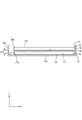
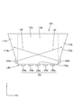
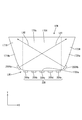
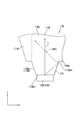
- FIG. 2 is a plan view schematically showing the liquid crystal display device according to the first embodiment.
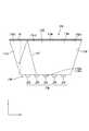
- Sectional view along the short direction of the liquid crystal display device (sectional view taken along line AA in FIG. 1)
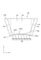
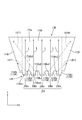
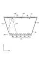
- Top view of lighting device The top view which represented typically the light-guide plate and LED row
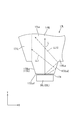
- column utilized with the illuminating device of Embodiment 10. 12 is an enlarged view of the LED as the side light source shown in FIG. 12 and the side light incident portion facing the LED.
- FIG. 11 The top view which represented typically the light-guide plate and LED row
- FIG. 12 The top view which represented typically the light-guide plate and LED row
- FIG. 13 The enlarged plan view of the light-incidence part of the light-guide plate utilized with the illuminating device of Embodiment 14.
- FIG. 16 The top view which represented typically the light-guide plate and LED row
- FIG. 17 The top view which represented typically the light-guide plate and LED row
- Embodiment 1 of the present invention will be described with reference to FIGS. 1 to 3.
- the illumination device 14 and the liquid crystal display device 10 including the illumination device 14 are illustrated.
- an X axis, a Y axis, and a Z axis are shown.
- the lighting device 14 and the like will be described with the upper side shown in FIG. 2 as the front side and the lower side in the figure as the back side.
- FIG. 1 is a plan view schematically showing the liquid crystal display device 10 according to the first embodiment.
- FIG. 2 is a cross-sectional view of the liquid crystal display device 10 along the short direction (a cross-sectional view taken along line AA in FIG. 1). ).
- the liquid crystal display device 10 has an inverted trapezoidal shape as a whole when viewed from the front side.
- the liquid crystal display device 10 mainly includes a liquid crystal panel (display panel) 11 for displaying an image, a touch panel 12 for inputting positional information within the display surface 11a of the liquid crystal panel 11, a transparent touch panel 12 and the like.
- a cover panel 13 and an illumination device (backlight device) 14 as an external light source for supplying light to the liquid crystal panel 11 are provided.
- the touch panel 12 is made of, for example, a projection capacitive type, and is laminated on the front side (display surface 11a side) of the liquid crystal panel 11 via an adhesive layer (not shown).
- the cover panel 13 consists of plate-shaped tempered glass etc., and is laminated
- the liquid crystal panel 11, the touch panel 12, and the cover panel 13 each have an inverted trapezoidal shape and are integrated in a stacked state.
- the liquid crystal panel 11 has a configuration in which a pair of substantially transparent glass substrates having a reverse trapezoidal shape in plan view are bonded together with a predetermined gap (cell gap) therebetween, and liquid crystal is sealed between the two substrates. It has become.
- the array substrate disposed on the back side includes source wiring and gate wiring orthogonal to each other, a switching element (for example, TFT) connected thereto, a pixel electrode connected to the switching element, and an orientation It has a membrane.
- the CF (color filter) substrate disposed on one front side is a color filter, counter electrode, alignment film, or the like in which colored portions such as R (red), G (green), and B (blue) are arranged in a predetermined arrangement. It has.
- polarizing plates are attached to the outer sides of both substrates.
- the liquid crystal panel 11 is driven by an active matrix system, and displays an image on the display surface 11a using light supplied from the illumination device 14.
- the range (display region R) of the display surface 11 a of the liquid crystal panel 11 that is visually recognized is shown through the cover panel 13.
- the illuminating device 14 emits planar light from the back side (back side) toward the range (display region R) of the liquid crystal panel 11.
- the illumination device 14 is a so-called edge light type (side light type), and mainly includes a housing 15, an optical sheet 16, an LED unit LU, a light guide plate 17, a reflection sheet 18, and the like.
- FIG. 3 is a plan view of the illumination device 14.
- FIG. 4 shows the illumination device 14 with the optical sheet 16 and the like removed.
- the housing 15 is made of, for example, a synthetic resin and has a shallow box shape with an upper opening.
- the casing 15 includes an inverted trapezoidal bottom portion 15a and a peripheral wall portion 15b rising from the periphery of the bottom portion 15a when viewed from the front side.
- the reflection sheet 18, the light guide plate 17, and the optical sheet 16 are accommodated in a stacked manner in this order.
- a liquid crystal panel 11, a touch panel 12, a cover panel 13 and the like are also housed.
- the cover panel 13 is disposed so as to close the opening of the housing 15.
- the optical sheet 16 has an inverted trapezoidal shape when viewed from the front side, like the light guide plate 17 and the like.
- the optical sheet 16 is composed of a laminate of a diffusion sheet, a lens sheet, and a reflective polarizing sheet.
- the optical sheet 16 is placed on the front surface of the light guide plate 17 so as to cover the light guide plate 17.
- the size of the optical sheet 16 is set to be approximately the same as the size of the plate surface of the light guide plate 17.
- the structure of the optical sheet 16 is not restricted to the said laminated body.
- the LED unit LU mainly includes a plurality of LEDs (light sources) 20 and an LED substrate 21.
- the LED unit LU has a longitudinal shape as a whole, and is arranged along one end face of the light guide plate 17.
- the LED 20 has a structure (a so-called LED package) in which an LED chip is sealed with a resin material in the shape of a substrate fixed to the LED substrate 21.
- the LED chip mounted on the substrate unit has a single main emission wavelength. Specifically, those that emit blue light in a single color are used as LED chips.
- a phosphor that emits a predetermined color when excited by blue light emitted from the LED chip is dispersed and blended.
- the resin material is generally configured to emit white light.
- a fluorescent substance you may use what combined suitably among yellow fluorescent substance which emits yellow light, green fluorescent substance which emits green light, and red fluorescent substance which emits red light, for example. They may be used alone.
- the LED 20 is a so-called side light emitting type in which a main light emitting surface 21 a is a surface perpendicular to the mounting surface with respect to the LED substrate 21.
- the LED 20 emits light having a predetermined spread (directivity) around the optical axis L from the main light emitting surface 21a.
- the optical axis L of the emitted light is in a state perpendicular to the central portion of the main light emitting surface 21a.
- the LED substrate 21 has a plate shape as a whole.
- the LED substrate 21 is disposed between the light guide plate 17 and the peripheral wall portion 15b so as to be placed on the bottom portion 15a so that each LED 20 faces the end face of the light guide plate 17.
- the LED substrate 20 is fixed to the bottom portion 15a of the housing 15 by using fixing means (adhesive, screws, etc.) not shown.
- the LED substrate 21 is mainly composed of an elongated base material made of a metal material such as an aluminum material, an insulating layer made of a synthetic resin formed on the base material, and a copper foil formed on the insulating layer. And a reflection layer (reflection film) made of a white insulating film formed on the insulating layer so as to cover the wiring pattern.
- a reflection layer reflection film
- a plurality of LEDs 20 are surface-mounted on a front surface (mounting surface) 21 a of the LED substrate 21.
- the LEDs 20 are arranged in a line along the longitudinal direction of the LED substrate 21 on the plate surface 21 a to form an LED array (light source array) 22.
- Each LED 20 has the same external shape (rectangular shape).
- Each LED 20 is connected in series with each other by a wiring pattern formed on the LED substrate 21.
- the reflective sheet 18 has an inverted trapezoidal shape, like the bottom 15a of the housing 15 when viewed from the front side.
- the reflective sheet 18 of the present embodiment is made of a white foamed plastic sheet (for example, a foamed polyethylene terephthalate sheet).
- the reflection sheet 18 is accommodated in the housing 15 so as to be placed on the bottom 15 a so as to cover the back side of the light guide plate 17. That is, the reflection sheet 18 is sandwiched between the light guide plate 17 and the bottom portion 15a.
- the light guide plate 17 has an inverted trapezoidal shape whose lower side is shorter than the upper side, as in the liquid crystal panel 11 and the like, and is made of a transparent plate-like member having a predetermined thickness. Become.
- the light guide plate 17 is manufactured from a synthetic resin material having a refractive index higher than that of air and transparent (for example, an acrylic resin such as PMMA or a polycarbonate resin).
- the light guide plate 17 has a plate shape that is thicker than the optical sheet 16.
- the light guide plate 17 is formed by inserting a locking pin (not shown) standing on the side portion 15a of the housing 15 into a hole (not shown) provided on the back side. 15 is fixed.
- a plate-like reflection / scattering portion (not shown) that reflects or scatters light inside the light guide plate 17 is patterned on the back surface of the light guide plate 17 so as to have a predetermined in-plane distribution.
- the reflection / scattering part is formed by silk printing or embossing.
- the light guide plate 17 is divided into a plate-like main body 170 facing the above-described LED row (light source row) 22 and plate-like laterally extending portions 171 and 172 respectively extending on both sides of the main body 170. It is done.
- the main body 170 has a generally rectangular shape in plan view, and has one end 170a facing the LED row 22.
- the end portion 170 a is a light incident portion 170 a through which light emitted from the LEDs 20 (20 a, 20 b, 20 c, 20 d, 20 e) enters the light guide plate 17.
- the laterally extending portions 171 and 172 are extended to the side of the main body portion 170 so as to spread outside the light incident portion 170a.
- the laterally extending portions 171 and 172 have a generally triangular shape in plan view as a whole, and gradually move outward (left and right direction in FIG. 3) from the light incident portion 170a side toward the opposite side. It has a shape that spreads out.
- Such side extending portions 171 and 172 are formed integrally with the main body portion 170.
- the laterally extending portion 171 is disposed on the left side of FIG. 3, and the laterally extending portion 172 is disposed on the right side, and these laterally extending portions 171 and 172 have a symmetrical relationship.
- the end portion 17b of the light guide plate 17 on the opposite side of the light incident portion 170a is constituted by the end portions of the side extension portion 171, the main body portion 170, and the side extension portion 172. .
- Such a light guide plate 17 has a lateral width (width in the X-axis direction) at the back side portion longer than a lateral width (width in the X-axis direction) of the light incident portion 170a.
- the light incident portion 170a side of the light guide plate 17 may be referred to as “front side” and the opposite side may be referred to as “back side”.
- the width in the left-right direction of the light guide plate 17 may be referred to as “lateral width” as described above.
- the light incident part 170a is arranged outside the main body side light incident part 170a1 for allowing light to enter the main body part 170 and the main body side light incident part 170a, and makes the light incident on the laterally extending portions 171 and 172. End side light incident portions 170a2 and 170a3 are provided.
- the main body side light incident portion 170a is composed of a strip-shaped end portion (end surface) of the flat main body portion 170 extending in the left-right direction.
- One end-side light incident portion 170a2 is for allowing light to enter the left side extending portion 171 and includes an end portion (end surface) of the flat main body portion 170 adjacent to the main body-side light incident portion 170a.
- the main body side light incident portion 170a is inclined with respect to the main body side light incident portion 170a so as to be directed to the left side extending portion 171.
- the other end side incident portion 170a3 is for making light incident on the right side extending portion 172, and is an end portion (end face) of the flat main body portion 170 adjacent to the main body side light incident portion 170a. Consists of. However, the end side incident portion 170a3 is inclined with respect to the main body side light incident portion 170a so as to be directed to the right side extending portion 172.
- the light incident portion 170a By the main body side light incident portion 170a disposed on the center side and the end side light incident portions 170a2 and 170a3 adjacent to each other so as to sandwich the light incident portion 170a, the light incident portion 170a generally has an end portion of the main body portion 170. It has a shape that is recessed in the back.
- the LED row 22 facing the light incident part 170a is composed of five LEDs 20 (20a, 20b, 20c, 20d, and 20e) for convenience of explanation.
- the LEDs 20 are arranged in a line from the left side to the right side in the order of LED 20a, LED 20b, LED 20c, LED 20d, and LED 20e.
- These five LEDs 20 are arranged on the center side, and are arranged on the outside of the center side light source, a center side LED (center side light source) set so that the optical axis L is arranged inside the main body 170,
- the optical axis L is divided into end-side LEDs (end-side light sources) set so as to be disposed inside the laterally extending portions 171 and 172.
- the three LEDs 20 (LED 20b, LED 20c, LED 20d) arranged on the center side of the LED row 22 are arranged such that their optical axes Lb, Lc, Ld are arranged only in the main body 170. It corresponds to the set center side LED (center side light source).
- the LED 20a disposed at the left end of the LED row 22 corresponds to an end LED (end light source) set so that its optical axis La is disposed at the left side extending portion 171.
- the LED 20e disposed at the right end of the LED row 22 corresponds to an end-side LED (end-side light source) set so that the optical axis Le is disposed on the right side extending portion 172.
- the optical axis La of the LED 20a is arranged in the side extending portion 171 after entering the main body 170 from the end side light incident portion 170a2.
- the optical axis Le of the LED 20e is also arranged in the side extending portion 172 after entering the main body 170 from the end side light incident portion 170a3.
- the optical axis L of the end-side LED (end-side light source) is set so as to be disposed at least in the laterally extending portions 171 and 172 after entering the main body 170 from the end-side light incident portions 170a2 and 170a3.
- each LED 20 and the light incident portion 170a are in close contact with each other. It is shown.
- the LED 20a is inclined so as to face the outside (left side) so that light can be irradiated toward the left side extending portion 171. Further, the LED 20e is inclined so as to face the outside (right side) so that light can be irradiated toward the right side extending portion 172.
- the front plate surface 17a of the light guide plate 17 is a light emitting portion 17a that emits light incident from the light incident portion 170a toward the liquid crystal panel 11 side.
- the light emitting portion 17a includes a front plate surface of the main body 170, a front plate surface of the left side extending portion 171a, and a front plate surface of the right side extending portion 172a.
- a portion corresponding to the display region R is shown on the plate surface 17 a of the light guide plate 17.
- the light guide plate 17 is configured to emit light uniformly from at least a portion corresponding to the display region R.
- the lighting device 14 appropriately includes a known configuration such as a frame in addition to the configuration described above.
- the liquid crystal display device 10 When the liquid crystal display device 10 displays an image on the display surface 11a of the liquid crystal panel 11, the liquid crystal display device 10 causes each LED 20 of the LED unit LU included in the illumination device 14 to emit light (light on). When each LED 20 (LED 20 a, 20 b, 20 c, 20 d, 20 e) emits light, light from each LED 20 enters the light guide plate 17 from a light incident portion 170 a that is an end on the near side of the light guide plate 17.
- the incident light is reflected by the reflection sheet 18 laid on the back side of the light guide plate 17 or a reflection / scattering portion (not shown) formed on the back surface of the light guide plate 17. While proceeding, the light is emitted from the light emitting portion 17a formed of the front plate surface.
- the light from the LED 20a mainly enters the light guide plate 17 from the end side light incident portion 170a2 and travels while being repeatedly reflected in the light guide plate 17 toward the left side extending portion 171.
- the light from the LED 20 e mainly enters the light guide plate 17 from the end side light incident portion 170 a and travels while being repeatedly reflected and the like in the light guide plate 17 toward the right side extending portion 172.
- light from the LEDs 20b, 20c, and 20d mainly enters the light guide plate 17 from the main body side light incident portion 170a and travels through the main body portion 170 while repeating reflection and the like.
- the light emitted from the light emitting portion 17a of the light guide plate 17 passes through the optical sheet 16 and spreads in a planar shape, and illuminates the liquid crystal panel 11 from the back side.
- the liquid crystal panel 11 displays an image on the display surface 11a using the light from the illumination device 14.
- each end side light incident part 170a2, 170a3 of the light-guide plate 17, and end side LED (end side light source) 20a, 20e supply the light to the side extension part 171,172. It has become.
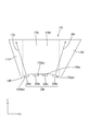
- FIG. 4 is a plan view schematically showing the light guide plate 17A and the LED array 22A used in the illumination device of the second embodiment.
- the light guide plate 17A generally has an inverted trapezoidal shape in plan view as in the first embodiment, and includes a substantially rectangular main body 170A, a laterally extending portion 171A shown on the left side of FIG.
- the front end (LED unit LUA side) end portion 170Aa of the main body portion 170A has a generally concave shape that is recessed toward the back side.
- the front end 170Aa of the main body 170A is a light incident portion 170Aa into which light from each LED 20A (20Aa, 20Ab, 20Ac, 20Ad, 20Ae, 20Af, 20Ag) of the LED array 22A is incident.
- the LED array 22A includes a larger number of LEDs 20A than those in the first embodiment, and the interval between adjacent LEDs 20A is narrow.
- the light incident part 170Aa includes a main body side light incident part 170Aa1 for allowing light to enter the main body part 170A, an end side light incident part 170Aa2 for allowing light to enter the left side extending part 171A, and a right side.
- An end-side light incident portion 170Aa3 for allowing light to enter the unidirectionally extending portion 172A is provided.
- the end side light incident portions 170Aa2 and 170Aa3 are set to be relatively longer than the main body side light incident portion 170Aa1 as compared with the first embodiment.
- the two LEDs 20Aa and 20Ab are arranged to face the end-side light incident portion 170Aa2 as end-side LEDs (end-side light sources), and the two LEDs 20Af, 20Ag is arranged so as to face as an end-side LED (end-side light source).
- the optical axes LAa and LAb of the two LEDs 20Aa and 20Ab are arranged in the left side extending portion 171A, and the optical axes LAf of the two LEDs 20Ag and 20Ag are arranged in the right side extending portion 172A. , LAg.
- the three LEDs 20A (20Ac, 20Ad, 20Ae) arranged on the center side of the LED array 22A have center-side LEDs (center-side light sources) set so that their optical axes are arranged in the main body 170A. ).
- a plurality (two) of LEDs may be assigned to the end side light incident portions 170Aa2 and 170Aa3.
- the side light incident portions 170Aa2 and 170Aa3 of the light guide plate 17A, the LEDs 20Aa and 20Ab, and the LEDs 20Af and 20Ag as end side LEDs (end side light sources) are provided on the side extending portions 171A and 172A.
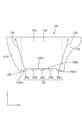
- FIG. 5 is a plan view schematically showing the light guide plate 17B and the LED array 22B used in the illumination device of the third embodiment.
- the light guide plate 17B generally has an inverted trapezoidal shape in plan view as in the first embodiment.
- the light guide plate 17B has a substantially rectangular main body 170B, a laterally extending portion 171B shown on the left side of FIG.
- the front side (LED unit LUB side) end 170Ba of the main body 170B has a generally concave shape that is recessed toward the back side.
- the front end 170Ba of the main body 170B is a light incident part 170Ba into which light from each LED 20B (20Ba, 20Bb, 20Bc, 20Bd, 20Be, 20Bf, 20Bg) of the LED array 22B is incident.
- the LED row 22B has a larger number of LEDs 20B than those in the first embodiment, and the interval between adjacent LEDs 20B is narrow.
- the light incident part 170Ba includes a main body side light incident part 170Ba1 for allowing light to enter the main body part 170B, an end side light incident part 170Ba2 for allowing light to enter the left side extending part 171B, and a right side.
- An end-side light incident portion 170Ba3 for entering light is provided in the laterally extending portion 172B.
- the end side light incident portions 170Ba2 and 170Ba3 are inclined with respect to the main body side light incident portion 170Ba1, the inclination thereof is gentler than that of the first embodiment.
- one LED 20Ba is arranged to face the end-side light incident part 170Ba2 as an end-side LED (end-side light source), and one LED 20Ba is arranged to face the end-side light incident part 170Ba3.
- the LEDs 20Bg are arranged so as to face each other as an end-side LED (end-side light source).
- the optical axis LBa of one LED 20Ba is arranged in the left side extending portion 171B, and the optical axis LBg of one LED 20Bg is arranged in the right side extending portion 172B.
- the five LEDs 20B (20Bb, 20Bc, 20Bd, 20Be, 20Bf) arranged on the center side of the LED row 22B are center-side LEDs set so that their optical axes are arranged in the main body 170B. (Central light source).
- the main body side light incident portion 170Ba1 of the present embodiment is composed of three flat portions (end faces) connected in a concave shape, and these are the main body side light incident portion 170Ba1. Consists of a portion facing the LED 20Bb, a portion facing the LEDs 20Bc, 20Bd, and 20Be, and a portion facing the LED 20Bf.
- the light incident portion 170Bb includes a portion in which five flat portions (end surfaces) are connected in a concave shape including the end side light incident portions 170Ba2 and 170Ba3.
- the light incident portion 170Bb may be formed from a portion in which a plurality of flat portions (end surfaces) are connected in a concave shape.
- the light incident part 170Bb has such a configuration, it is easy to manage the clearance between the LED 20B and the light incident part 170Bb.
- the end-side light incident portions 170Ba2 and 170Ba3 of the light guide plate 17B, the LED 20Ba as the end-side LED (end-side light source), and the LED 20Bg supply light to the laterally extending portions 171B and 172B.
- Supply section By providing such a supply unit, it is possible to supply light to the laterally extending portions 171B and 172B of the light guide plate 17B, and light emitted from the front side of the laterally extending portions 171B and 172B is transmitted to the main body portion 170B. It is suppressed that it becomes relatively darker than the light emitted from the front side. Therefore, in the illuminating device of this embodiment, the brightness nonuniformity of the light radiate
- FIG. 6 is a plan view schematically showing the light guide plate 17C and the LED array 22C used in the illumination device of the fourth embodiment.
- the light guide plate 17C generally has an inverted trapezoidal shape in plan view as in the first embodiment, and includes a substantially rectangular main body 170C, a laterally extending portion 171C shown on the left side of FIG.
- the front end (LED unit LUC side) end portion 170Ca of the main body portion 170C has a generally concave shape that is recessed toward the back side.
- the end 170Ca of the present embodiment has a gentle arc shape.
- the end portion 170Ca is a light incident portion 170Ca into which light from each LED 20C (20Ca, 20Cb, 20Cc, 20Cd, 20Ce) of the LED row 22C is incident.
- the light incident part 170Ca includes a main body side light incident part 170Ca1 for allowing light to enter the main body part 170C, an end side light incident part 170Ca2 for allowing light to enter the left side extending part 171C, and a right side.
- An end-side light incident portion 170Ca3 for allowing light to enter the unidirectionally extending portion 172C is provided.
- the main body side light incident portion 170Ca1 and the end side light incident portions 170Ca2 and 170Ca3 each have a gently curved surface, and they are connected in a single arc shape.
- one LED 20Ca is arranged to face the end-side light incident part 170Ca2 as an end-side LED (end-side light source), and one LED 20Ca is disposed to the end-side light incident part 170Ca3.
- the LEDs 20Ce are arranged so as to face each other as end LEDs (end light sources).
- the optical axis LCa of one LED 20Ca is arranged in the left side extending portion 171C, and the optical axis LCe of one LED 20Ce is arranged in the right side extending portion 172C.
- the three LEDs 20Cb, 20Cc, and 20Cd arranged on the center side of the LED row 22C are center-side LEDs (center-side light sources) set so that their optical axes are arranged in the main body 170C. ing.
- the end-side light incident portions 170Ca2 and 170Ca3 of the light guide plate 17C, the LED 20Ca as the end-side LED (end-side light source), and the LED 20Ce supply light to the laterally extending portions 171C and 172C.
- Supply section By providing such a supply unit, it is possible to supply light to the laterally extending portions 171C and 172C of the light guide plate 17C, and light emitted from the front side of the laterally extending portions 171C and 172C It is suppressed that it becomes relatively darker than the light emitted from the front side. Therefore, in the illuminating device of this embodiment, the brightness nonuniformity of the light radiate
- FIG. 7 is a plan view schematically showing the light guide plate 17D and the LED array 22D used in the illumination device of the fifth embodiment.
- the light guide plate 17D as a whole is asymmetrical although it has an inverted trapezoidal shape in plan view as in the first embodiment.
- Such a light guide plate 17D includes a substantially rectangular main body 170D, a small side extending portion 171D shown on the left side of FIG. 7, and a large side extending portion 172D shown on the right side.
- An end 170Da on the front side (LED unit LUD side) of the main body 170D has a generally concave shape that is recessed toward the back.
- the end portion 170Da is a light incident portion 170Da into which light from each LED 20D (20Da, 20Db, 20Dc, 20Dd) of the LED row 22D is incident.
- the light incident part 170Da includes a main body side light incident part 170Da1 for allowing light to enter the main body part 170D, an end side light incident part 170Da2 for allowing light to enter the left side extending part 171D, and a right side.
- An end-side light incident portion 170Da3 for entering light is provided in the direction extending portion 172D.
- the end side light incident portions 170Da2 and 170Da3 are inclined with respect to the main body side light incident portion 170Da1.
- one LED 20Da is arranged so as to face the end-side light incident portion 170Da2 as an end-side LED (end-side light source), and one end of the end-side light incident portion 170Da3.
- the LEDs 20Dd are arranged so as to face each other as end LEDs (end light sources).
- the optical axis LDa of one LED 20Ca is arranged in the left side extending portion 171D, and the optical axis LDd of one LED 20Dd is arranged in the right side extending portion 172D.
- the two LEDs 20Db and 20Dc arranged on the center side of the LED row 22D are center-side LEDs (center-side light sources) set so that their optical axes are arranged in the main body 170D. .
- the end-side light incident portions 170Da2 and 170Da3 of the light guide plate 17D, the LED 20Da as the end-side LED (end-side light source), and the LED 20Dd supply light to the laterally extending portions 171D and 172D.
- Supply section By providing such a supply unit, it is possible to supply light to the laterally extending portions 171D and 172D of the light guide plate 17D, and light emitted from the front side of the laterally extending portions 171D and 172D is transmitted from the main body portion 170D. It is suppressed that it becomes relatively darker than the light emitted from the front side. Therefore, in the illuminating device of this embodiment, the brightness nonuniformity of the light radiate
- FIG. 8 is a plan view schematically showing the light guide plate 17E and the LED array 22E used in the illumination device of the sixth embodiment.
- the light guide plate 17E is generally asymmetrical although it has an inverted trapezoidal shape in plan view.
- a light guide plate 17E includes a substantially rectangular main body 170E, a side extending portion 171E shown on the left side of FIG. 8, and a side extending portion 172E shown on the right side.
- An end 170Ea on the near side (LED unit LUE side) of the main body 170E has a shape that is recessed in the back side as a whole.
- the end portion 170Ea is a light incident portion 170Ea into which light from each LED 20E (20Ea, 20Eb, 20Ec, 20Ed, 20Ee) of the LED row 22E is incident.
- the light incident part 170Ea is an end composed of a main body side light incident part 170Ea1 composed of a flat end surface for allowing light to enter the main body part 170E, and a flat end surface composed of light entering the left side extending part 171E.
- a side light incident portion 170Ea2 and an end side light incident portion 170Ea3 formed of a flat end surface for entering light into the right side extending portion 172E are provided.
- the end side light incident portions 170Ea2 and 170Ea3 are inclined with respect to the main body side light incident portion 170Ea1 so as to face the side extending portions 171E and 172E, respectively.
- one LED 20Ea is arranged to face the end-side light incident portion 170Ea2 as an end-side LED (end-side light source), and one end of the end-side light incident portion 170Ea3.
- the LEDs 20Ee are arranged so as to face each other as end LEDs (end light sources).
- the optical axis LEa of one LED 20Ea is disposed in the left side extending portion 171E, and the optical axis LEe of one LED 20Ee is disposed in the right side extending portion 172E.
- the three LEDs 20Eb, 20Ec, and 20Ed arranged on the center side of the LED row 22E serve as center-side LEDs (center-side light sources) that are set so that their optical axes are arranged in the main body 170E. ing.
- the end-side light incident portions 170Ea2 and 170Ea3 of the light guide plate 17E, the LED 20Ea as the end-side LED (end-side light source), and the LED 20Ee supply light to the laterally extending portions 171E and 172E.
- Supply section By providing such a supply unit, it becomes possible to supply light to the laterally extending portions 171E and 172E of the light guide plate 17E, and the light emitted from the front side of the laterally extending portions 171E and 172E is transmitted from the main body portion 170E. It is suppressed that it becomes relatively darker than the light emitted from the front side. Therefore, in the illuminating device of this embodiment, the brightness nonuniformity of the light radiate
- FIG. 9 is a plan view schematically showing the light guide plate 17F and the LED array 22F used in the illumination device of the seventh embodiment.
- the light guide plate 17F is generally asymmetrical although it has an inverted trapezoidal shape in plan view.
- the light guide plate 17F has one through-hole 31 having a circular cross-sectional view that penetrates in the thickness direction, and one notch 32 formed by notching the side (right side in FIG. 9) end. Is formed.
- Such a light guide plate 17F includes a substantially rectangular main body 170F, a laterally extending portion 171F shown on the left side of FIG. 9, and a laterally extending portion 172F shown on the right side.
- the above-described through hole 31 is formed across the left side extending portion 171F and the main body portion 170F, and the notch 32 extends across the right side extending portion 172F and the main body portion 170F. Is formed.
- An end 170Fa on the front side (LED unit LUF side) of the main body 170F has a shape that is concavely recessed toward the back.
- the end portion 170Fa is a light incident portion 170Fa into which light from each LED 20F (20Fa, 20Fb, 20Fc, 20Fd, 20Fe) of the LED row 22F is incident.
- the light incident portion 170Fa is an end made of a main body side light incident portion 170Fa1 that is a flat end surface for allowing light to enter the main body portion 170F, and a flat end surface that is used for making light enter the left side extending portion 171F.
- a side light incident portion 170Fa2 and an end side light incident portion 170Fa3 having a flat end surface for allowing light to enter the right side extending portion 172F are provided.
- the end side light incident portions 170Fa2 and 170Fa3 are inclined with respect to the main body side light incident portion 170Fa1 so as to face the side extending portions 171F and 172F, respectively.
- one LED 20Fa is arranged so as to face the end-side light incident portion 170Fa2 as an end-side LED (end-side light source), and one end of the end-side light incident portion 170Fa3.
- the LEDs 20Fe are arranged so as to face each other as end LEDs (end light sources).
- the optical axis LFa of one LED 20Fa is arranged in the left side extending portion 171F.
- the optical axis LFa of the LED 20Fa is set to cross the through hole 31.
- the optical axis LFe of one LED 20Fe is arranged in the right side extending portion 172F.
- the optical axis LFe of the LED 20Fe is set so as to cross the notch 32.
- the three LEDs 20Fb, 20Fc, and 20Fd arranged on the center side of the LED array 22F are center-side LEDs (center-side light sources) set so that their optical axes are arranged in the main body 170F. .
- the optical axis LFa of the LED 20Fa crosses the through-hole 31 and the optical axis LFe of the LED 20Fe crosses the notch 32 is illustrated, but this is an embodiment of the present invention. Is not limited to this.
- the optical axis of the LED may be set so as not to cross a through hole or a notch.
- the end-side light incident portions 170Fa2 and 170Fa3 of the light guide plate 17F, the LED 20Fa as the end-side LED (end-side light source), and the LED 20Fe supply light to the laterally extending portions 171F and 172F.
- Supply section By providing such a supply unit, it is possible to supply light to the laterally extending portions 171F and 172F of the light guide plate 17F, and light emitted from the front side of the laterally extending portions 171F and 172F is transmitted to the main body portion 170F. It is suppressed that it becomes relatively darker than the light emitted from the front side. Therefore, in the illuminating device of this embodiment, the brightness nonuniformity of the light radiate
- FIG. 10 is a plan view schematically showing the light guide plate 17G and the LED array 22G used in the illumination device of the eighth embodiment.
- the light guide plate 17G as a whole has an inverted trapezoidal shape that is symmetrical in plan view.
- the light guide plate 17G includes a rectangular main body 170G, a triangular (inverted triangle) side extending portion 171G shown on the left side of FIG. 10, and a triangular (inverted triangle) side extending portion 172G shown on the right side.
- An end portion 170Ga (that is, an end portion on the near side of the light guide plate 17G) on the front side (LED unit LUG side) of the main body portion 170G has a flat shape extending in the left-right direction.
- the end portion 170Ga is opposed to the LED row 22G included in the LED unit LUG, and is a light incident portion 170Ga into which light from each LED 20G (20Ga, 20Gb, 20Gc, 20Gd, 20Ge) of the LED row 22G is incident.
- the LED unit LUG of the present embodiment mainly supplies light to the main body 170G.
- the illumination device of the present embodiment includes LEDs 200a and 200b as two auxiliary light sources in addition to the LED unit LUG.
- the end portions arranged on both sides of the light guide plate 17G are each composed of an inclined end portion 171Ga of the side extending portion 171G and an inclined end portion 172Ga of the side extending portion 172G.
- the inclined end portion 171Ga and the inclined end portion 172Ga face each other with the light incident portion 170Ga interposed therebetween.
- the LED 200a as a sub light source is disposed so as to face the inclined end portion 171Ga in the left side extending portion 171G.
- the LED 200a which is a sub-light source, is a light source for entering light from the inclined end portion 171Ga included in one side extending portion 171G and supplying the light toward the other side extending portion 172G on the opposite side.
- the LED 200a is arranged so as to face the outer end portion 171Ga of one side extending portion 171G, and supplies light toward the other side extending portion 172G while obliquely crossing the main body portion 170G from the left side to the right side.
- FIG. 10 shows the optical axis LG1 of the LED 200a.
- an LED 200b as a sub light source is disposed so as to face the inclined end portion 172Ga in the right side extending portion 172G.
- the LED 200b which is a sub-light source, is a light source for entering light from the inclined end portion 172Ga included in the other side extending portion 172G and supplying the light toward the other side extending portion 171G on the opposite side. .
- the LED 200b is arranged to face the outer end 172G of the other side extending portion 172G, and supplies light toward the other side extending portion 171G while crossing the main body portion 170G obliquely from the right side to the left side.
- FIG. 10 shows the optical axis LG2 of the LED 200b.
- the LEDs 200a and 200b emit light toward the laterally extending portions 171G and 172G, unlike the LEDs 20G constituting the LED unit LUG.
- the end portions 171Ga and 172Ga are sub-light source light incident portions for allowing light from the LEDs 200a and 200b as sub-light sources to enter.
- the LEDs 200a and 200b as sub-light sources are supply units that supply light to the laterally extending portions 171G and 172G.
- a supply unit By providing such a supply unit, it is possible to supply light to the laterally extending portions 171G and 172G of the light guide plate 17G, and light emitted from the front side of the laterally extending portions 171G and 172G is transmitted from the main body portion 170G. It is suppressed that it becomes relatively darker than the light emitted from the front side. Therefore, in the illuminating device of this embodiment, the brightness
- FIG. 11 is a plan view schematically showing the light guide plate 17H and the LED array 22H used in the illumination device of the ninth embodiment.
- the light guide plate 17H is generally bilaterally symmetric in plan view, and has a substantially inverted trapezoidal shape with a rounded bottom side.
- the light guide plate 17H includes a substantially rectangular main body 170H, a substantially triangular (substantially inverted) side extending portion 171H shown on the left side of FIG. 11, and a substantially triangular (substantially inverted triangular) side shown on the right side. It consists of the direction extension part 172H.
- the front side (LED unit LUH side) end 170Ha (that is, the front side end of the light guide plate 17H) of the main body 170H has a gentle arc shape that swells toward the LED unit LUH and extends in the left-right direction. .
- the end 170Ha is opposed to the LED row 22H included in the LED unit LUH, and serves as a light incident portion 170Ha into which light from each LED 20H (20Ha, 20Hb, 20Hc, 20Hd, 20He) of the LED row 22H is incident.
- the LED unit LUH of the present embodiment mainly supplies light to the main body 170H.
- the illumination device of the present embodiment includes LEDs 200Ha and 200Hb as two auxiliary light sources in addition to the LED unit LUH.
- the end portions arranged on both sides of the light guide plate 17H are each composed of an inclined end portion 171Ha of the side extending portion 171H and an inclined end portion 172Ha of the side extending portion 172H.
- the inclined end portion 171Ha and the inclined end portion 172Ha are in a state of facing each other across the light incident portion 170Ha.
- the inclined end portions 171Ha and 172Ha have rounded shapes as they approach the light incident portion 170Ha.
- the LED 200Ha as a sub light source is arranged so as to face the inclined end portion 171Ha in the left side extending portion 171H.
- the LED 200Ha which is a sub-light source, is a light source that receives light from an inclined end portion 171Ha included in one side extending portion 171H and supplies light toward the other side extending portion 172H on the opposite side.
- the LED 200Ha is arranged so as to face the outer end portion 171Ha of one side extending portion 171H, and supplies light toward the other side extending portion 172H while crossing the main body portion 170H obliquely from the left side to the right side.
- FIG. 11 shows the optical axis LH1 of the LED 200Ha.
- an LED 200Hb as a sub light source is disposed so as to face the inclined end portion 172Ha in the right side extending portion 172H.
- the LED 200Hb which is a sub-light source, is a light source for entering light from the inclined end portion 172Ha included in the other side extending portion 172H and supplying the light toward the other side extending portion 171H on the opposite side. .
- the LED 200Hb is arranged so as to face the outer end 172H of the other side extending portion 172H, and supplies light toward the other side extending portion 171H while crossing the main body portion 170H obliquely from the right side to the left side.
- FIG. 11 shows the optical axis LH2 of the LED 200Hb.
- the LEDs 200Ha and 200Hb emit light toward the laterally extending portions 171H and 172H, unlike the LEDs 20H constituting the LED unit LUH.
- the end portions 171Ha and 172Ha are sub-light source light incident portions that allow the light from the LEDs 200Ha and 200Hb as sub-light sources to enter.
- the LEDs 200Ha and 200Hb as sub-light sources serve as supply units for supplying light to the laterally extending portions 171H and 172H.
- a supply unit By providing such a supply unit, it is possible to supply light to the laterally extending portions 171H and 172H of the light guide plate 17H, and light emitted from the front side of the laterally extending portions 171H and 172H It is suppressed that it becomes relatively darker than the light emitted from the front side. Therefore, in the illuminating device of this embodiment, the brightness nonuniformity of the light radiate
- FIG. 12 is a plan view schematically showing the light guide plate 17I and the LED array 22I used in the illumination device of the tenth embodiment.
- the light guide plate 17I has a generally inverted trapezoidal shape that is symmetrical in plan view as a whole.
- the light guide plate 17I includes a substantially rectangular main body 170I, a substantially triangular (substantially inverted) side extending portion 171I shown on the left side of FIG. 12, and a substantially triangular (substantially inverted triangular) side shown on the right side. It consists of the direction extension part 172I.
- a light incident portion 173 for allowing light to enter the light guide plate 17I is formed at the front side (LED unit LUI side) end 170Ia (that is, the front side end of the light guide plate 17I) of the main body 170I. ing.
- the light incident section 173 includes a main body light incident section 173a that faces the three LEDs 20Ib, 20Ic, and 20Id on the center side of the LED array 22I included in the LED unit LUI and receives light from the LEDs 20Ib, 20Ic, and 20Id.
- the main body light incident portion 173a protrudes from the end portion 170Ia of the main body portion 17I toward the LED unit LUI side, and the portion facing each LED 20I (20Ib, 20Ic, 20Id) is a flat surface. It has become. Light from each LED 20I enters the main body portion 17I from this flat planar portion.
- the light incident portion 173 includes a side light incident portion 173b that faces the leftmost LED 20Ia in the LED row 22I included in the LED unit LUI and receives light from the LED 20Ia.
- the LED 20Ia is a light source for supplying light to the left side extending portion 171I, and may be referred to as a side light source (side LED).
- the side light incident portion 173b has a shape protruding from the end (one end) 170Ia of the main body portion 17I toward the LED 20Ia as the side light source, and is configured to receive light emitted from the LED 20Ia. ing.
- FIG. 13 is an enlarged view of the LED 20Ia as the side light source shown in FIG. 12 and the side light incident portion 173b facing the LED 20Ia.
- the side light incident portion 173b is opposite to the side light source LED 20Ia, and includes an incident end face 173b1 on which light from the LED 20Ia is incident, and a part of a peripheral wall surrounding the incident end face 173b1, and is incident from the incident end face 173b1.
- a reflection wall 173b2 for supplying the reflected light toward the laterally extending portion 171I by reflection or scattering.
- the incident end face 173b1 has a flat surface shape and faces the light exit surface of the LED 20Ia.
- the reflecting wall 173b2 is arranged on the side farther from the side extending portion 171I (on the LED 20Ib side on the center side) in the peripheral wall of the side light incident portion 173b.
- the reflection wall 173b2 is arranged along the optical axis L direction (Y-axis direction) of the LED 20I.
- the light LI11 heading toward the reflecting wall 173b2 at a predetermined angle with respect to the optical axis L is reflected by the reflecting wall 173b2, and then heads toward the laterally extending portion 171I.
- a part of the light emitted from the LED 20Ia toward the reflection wall 173b2 is reflected by the reflection wall 173b2 and supplied to the laterally extending portion 171I.
- the light incident portion 173 includes a side light incident portion 173c that faces the rightmost LED 20Ie in the LED row 22I included in the LED unit LUI and receives light from the LED 20Ie.
- the LED 20Ie is a light source for supplying light to the right side extending portion 172I, and may be referred to as a side light source (side LED).
- the side light incident portion 173c has a shape protruding from the end (one end) 170Ia of the main body portion 17I toward the LED 20Ie as the side light source, and is configured to receive light emitted from the LED 20Ie. ing.
- the side light incident portion 173c has a bilaterally symmetric relationship with the side light incident portion 173b described above, and its basic configuration is the same as that of the side light incident portion 173b, and a detailed description thereof will be omitted.
- a part of the light emitted from the LED 20Ie is reflected by the reflection wall 173c2, and becomes light LI12 toward the laterally extending portion 172I.
- each optical axis L of each LED 20I (20Ia, 20Ib, 20Ic, 20Id, 20Ie) constituting the LED unit LUI is set to be disposed in the main body 170I.
- the reflecting walls 173b2 and 173c2 are supply units that supply the light emitted from the LEDs 20Ia and 20Ie, which are side light sources, to the side extending portions 171I and 172I.
- a supply unit By providing such a supply unit, it is possible to supply light to the laterally extending portions 171I and 172I of the light guide plate 17I, and light emitted from the front side of the laterally extending portions 171I and 172I It is suppressed that it becomes relatively darker than the light emitted from the front side. Therefore, in the illuminating device of this embodiment, the brightness nonuniformity of the light radiate
- FIG. 14 is a plan view schematically showing the light guide plate 17J and the LED array 22J used in the illumination device of the eleventh embodiment.
- the light guide plate 17J generally has a generally inverted trapezoidal shape that is symmetrical in plan view.
- the light guide plate 17J includes a substantially rectangular main body 170J, a substantially triangular (substantially inverted) side extending portion 171J shown on the left side of FIG. 14, and a substantially triangular (substantially inverted triangular) side shown on the right side. It consists of the direction extension part 172J.
- a light incident portion 173J for allowing light to enter the light guide plate 17J is formed on the front side (LED unit LUJ side) end 170Ja (that is, the front side end of the light guide plate 17J) of the main body 170J. ing.
- the light incident portion 173 faces the three LEDs 20Jb, 20Jc, and 20Jd on the center side of the LED array 22J included in the LED unit LUJ, and receives three independent light beams from the LEDs 20Jb, Jc, and Jd.
- the main body light incident portion 173Ja is provided. That is, one main body light incident portion Ja is assigned to one LED 20J.
- Each main body light incident portion 173Ja has a shape protruding in a convex shape from the end portion 170Ja of the main body portion 17J toward the LED unit LUJ side, and the portion facing each LED 20J (20Jb, 20Jc, 20Jd) It has a flat surface. Light from each LED 20J enters the main body portion 17J from this flat surface portion.
- the light incident portion 173J includes a side light incident portion 173Jb that faces the leftmost LED 20Ja in the LED row 22J included in the LED unit LUJ, and from which light is incident.
- the LED 20Ja is a light source for supplying light to the left side extending portion 171J, and may be referred to as a side light source (side LED).
- the side light incident portion 173Jb has a shape that rises in a convex shape from the end (one end) 170Ja of the main body portion 17J toward the LED 20Ja as a side light source, and is configured to receive light emitted from the LED 20Ja. ing.
- the side light incident portion 173Jb is opposed to the side light source LED 20Ja, and includes an incident end surface 173Jb1 on which light from the LED 20J is incident, and a part of a peripheral wall surrounding the incident end surface 173Jb1, and is incident from the incident end surface 173Jb1.
- a reflecting wall 173Jb2 that supplies the reflected light toward the laterally extending portion 171J by reflection or scattering.
- the incident end surface 173Jb1 has a flat surface shape and faces the light exit surface of the LED 20Ja.
- the reflecting wall 173Jb2 is disposed on the side farther from the side extending portion 171J (on the LED 20Jb side on the center side) in the peripheral wall of the side light incident portion 173Jb.
- the reflection wall 173Jb2 is arranged along the optical axis L direction (Y-axis direction) of the LED 20I.
- the reflecting wall 173J At a predetermined angle with respect to the optical axis L.
- the light LJ11 going to b2 is reflected by the reflecting wall 173Jb2, and then goes to the side extending portion 171J.
- a part of the light emitted from the LED 20Ja toward the reflecting wall 173Jb2 is reflected by the reflecting wall 173Jb2 and supplied to the laterally extending portion 171J.
- the light incident portion 173J includes a side light incident portion 173Jc that faces the rightmost LED 20Je in the LED row 22J included in the LED unit LUJ, and from which light is incident.
- the LED 20Je is a light source for supplying light to the right side extending portion 172J, and may be referred to as a side light source (side LED).
- the side light incident portion 173Jc is formed in a convex shape from the end (one end) 170Ja of the main body portion 17J toward the LED 20Je as the side light source, and is configured to receive light emitted from the LED 20Je. ing.
- the side light incident portion 173Jc has a symmetrical relationship with the side light incident portion 173Jb described above, and the basic configuration is the same as that of the side light incident portion 173Jb, and a detailed description thereof will be omitted.
- a part of the light emitted from the LED 20Je is reflected by the reflecting wall 173Jc2, and becomes light LJ12 toward the laterally extending portion 172J.
- each optical axis L of each LED 20J (20Ja, 20Jb, 20Jc, 20Jd, 20Je) constituting the LED unit LUJ is set to be disposed in the main body 170J.
- the reflecting walls 173Jb2 and 173Jc2 are supply units that supply the light emitted from the LEDs 20Ja and 20Je that are the side light sources to the laterally extending portions 171J and 172J.
- a supply unit By providing such a supply unit, it is possible to supply light to the laterally extending portions 171J and 172J of the light guide plate 17J, and light emitted from the front side of the laterally extending portions 171J and 172J It is suppressed that it becomes relatively darker than the light emitted from the front side. Therefore, in the illuminating device of this embodiment, the brightness nonuniformity of the light radiate
- FIG. 15 is a plan view schematically showing the light guide plate 17K and the LED array 22K used in the illumination device of the twelfth embodiment.
- the light guide plate 17K as a whole has a generally inverted trapezoidal shape that is symmetrical in plan view.
- the light guide plate 17K includes a substantially rectangular main body 170K, a substantially triangular (substantially inverted triangle) side extending portion 171K shown on the left side of FIG. 15, and a substantially triangular (substantially inverted triangular) side shown on the right side. It consists of the direction extension part 172K.
- a light incident portion 173K for allowing light to enter the light guide plate 17K is formed at an end portion 170Ka (that is, an end portion on the near side of the light guide plate 17K) on the front side (LED unit LUK side) of the main body portion 170K. ing.
- the light incident portion 173 includes a main body light incident portion 173Ka that faces the one LED 20Kc on the center side of the LED row 22K included in the LED unit LUK and that receives light from the LED 20Kc.
- the main body light incident portion 173Ka protrudes from the end portion 170Ka of the main body portion 17K in a convex shape toward the LED unit LUK side, and a portion facing the LED 20Kc has a flat surface. Light from the LED 20Kc is incident on the main body 17K from this flat surface portion.
- the light incident portion 173K includes a side light incident portion 173Kb that faces the leftmost LED 20Ka in the LED row 22K included in the LED unit LUK and receives light therefrom.
- the LED 20Ka is a light source for supplying light to the left side extending portion 171K, and may be referred to as a side light source (side LED).
- the side light incident portion 173Kb has a shape that protrudes from the end (one end) 170Ka of the main body portion 17K toward the LED 20Ka as the side light source, and is configured to receive light emitted from the LED 20Ka. ing.
- the side light incident portion 173Kb is opposed to the side light source LED 20Ka, and includes an incident end surface 173Kb1 on which light from the LED 20Ka is incident, and a part of a peripheral wall surrounding the incident end surface 173Kb1, and is incident from the incident end surface 173Kb1.
- the incident end face 173Kb1 has a flat surface shape and faces the light exit surface of the LED 20Ka.
- the reflecting wall 173Kb2 is arranged on the side farther from the side extending portion 171K (on the LED 20Kb side on the center side) in the peripheral wall of the side light incident portion 173Kb. Note that the reflection wall 173Kb2 is inclined so as to approach the left side extending portion 171K from the near side toward the far side when viewed in plan.
- the reflecting wall 173K At a predetermined angle with respect to the optical axis L
- the light LK11 traveling toward b2 is reflected by the reflecting wall 173Kb2, and then travels toward the laterally extending portion 171K.
- a part of the light emitted from the LED 20Ka toward the reflecting wall 173Kb2 is reflected by the reflecting wall 173Kb2 and supplied to the laterally extending portion 171K.
- the light incident portion 173K includes a side light incident portion 173Kc that faces the rightmost LED 20Ke in the LED row 22K included in the LED unit LUK, and from which light is incident.
- the LED 20 Ke is a light source for supplying light to the right side extending portion 172 ⁇ / b> K, and may be referred to as a side light source (side LED).
- the side light incident portion 173Kc has a shape that protrudes from the end (one end) 170Ka of the main body portion 17K toward the LED 20Ke as a side light source, and is configured to receive light emitted from the LED 20Ke. ing.
- the side light incident portion 173Kc has a symmetrical relationship with the side light incident portion 173Kb described above, and the basic configuration is the same as that of the side light incident portion 173Kb, and a detailed description thereof will be omitted.
- a part of the light emitted from the LED 20 Ke is reflected by the reflecting wall 173Kc2 and becomes light LK12 directed to the side extending portion 172K.
- the light incident part 173K includes a side light incident part 173Kd that faces the second LED 20Kb from the left end in the LED row 22K included in the LED unit LUK, and from which light is incident.
- the LED 20Kb is a light source for supplying light to the left side extending portion 171K, and may be referred to as a side light source (side LED).
- the side light incident portion 173Kd has a shape that rises in a convex shape from the end (one end) 170Ka of the main body portion 17K toward the LED 20Kb as a side light source, and is configured to receive light emitted from the LED 20Kb. ing.
- the side light incident portion 173Kd is opposed to the side light source LED 20Kb, and includes an incident end surface 173Kd1 on which light from the LED 20Kb is incident, and a part of a peripheral wall surrounding the incident end surface 173Kd1, and is incident from the incident end surface 173Kd1.
- the incident end surface 173Kd1 has a flat surface shape and faces the light exit surface of the LED 20Kb.
- the reflection wall 173Kd2 is disposed on the side farther from the side extending portion 171K (on the LED 20Kc side on the center side) in the peripheral wall of the side light incident portion 173Kd. Note that the reflection wall 173Kd2 has a gentler slope than the reflection wall 173Kb2 of the side light incident portion 173Kb described above when viewed in plan, and is disposed along the optical axis L direction (Y-axis direction) of the LED 20K.
- the reflecting wall 173K At a predetermined angle with respect to the optical axis L
- the light LK13 traveling toward d2 is reflected by the reflecting wall 173Kd2, and then travels toward the laterally extending portion 171K.
- a part of the light emitted from the LED 20Kb toward the reflection wall 173Kd2 is reflected by the reflection wall 173Kd2 and supplied to the laterally extending portion 171K.
- the light incident portion 173 ⁇ / b> K opposes the second LED 20 ⁇ / b> Kd from the right end of the LED array 22 ⁇ / b> K included in the LED unit LUK, and the side light incident portion 173 ⁇ / b> Ke from which light is incident.
- the LED 20Kd is a light source for supplying light to the right side extending portion 172K, and may be referred to as a side light source (side LED).
- the side light incident portion 173Ke has a shape protruding from the end (one end) 170Ka of the main body portion 17K toward the LED 20Kd as a side light source, and is configured to receive light emitted from the LED 20Kd. ing.
- the side light incident portion 173Ke has a bilaterally symmetric relationship with the side light incident portion 173Kd described above, and its basic configuration is the same as that of the side light incident portion 173Kd, and a detailed description thereof will be omitted.
- a part of the light emitted from the LED 20Kd is reflected by the reflecting wall 173Ke2 and becomes light LK14 toward the side extending portion 172K.
- Each optical axis L of each LED 20K (20Ka, 20Kb, 20Kc, 20Kd, 20Ke) constituting the LED unit LUK is set to be disposed in the main body 170K.
- light is supplied to the left side extending portion 171K using the two reflecting walls 173Kb2 and 173Kd2, and the right side extending using the two reflecting walls 173Kc2 and the reflecting wall 173Ke2.
- the unit 172K is configured to supply light. Then, by appropriately setting the angles (angles with respect to the optical axis L) of the reflecting walls 173Kb2, 173Kd2, 173Kc2, and 173Ke2, light can be supplied to the laterally extending portions 171K and 172K.
- light may be supplied to the laterally extending portions 171K and 172K using a plurality of reflecting walls 173Jb2 and the like.
- each reflecting wall 173Kb2, 173Kd2, 173Kc2, 173Ke2 supplies the light emitted from each LED 20Ka, 20Kb, 20Kd, 20Ke which is a side light source to each side extending portion 171K, 172K. It is a supply section.
- a supply unit By providing such a supply unit, it is possible to supply light to the laterally extending portions 171K and 172K of the light guide plate 17K, and light emitted from the front side of the laterally extending portions 171K and 172K It is suppressed that it becomes relatively darker than the light emitted from the front side. Therefore, in the illuminating device of this embodiment, the brightness nonuniformity of the light radiate
- FIG. 16 is an enlarged view of the light incident portion 173L of the light guide plate 17L used in the illumination device of the thirteenth embodiment.
- the basic configuration other than the light incident portion 173L is the same as that of the above-described embodiment 12 and the like.
- a plurality of light incident portions 173L are provided at the front end 170La of the main body 170L of the light guide plate 17L.
- FIG. 16 shows a side light incident portion 173La for supplying light to the side extending portion 171L of the main body portion 170L.
- the side light incident portion 173La has a shape that rises in a convex shape from the end portion 170La of the main body portion 170L toward the LEDs 20L constituting the LED row 22L.
- the side light incident portion 173La has a symmetrical trapezoidal shape (reverse trapezoidal shape).
- the LED 20L is a light source for supplying light to the left side extending portion 171L, and corresponds to a side light source (side LED).
- the side light incident portion 173La is opposed to the side light source LED 20L, and includes an incident end surface 173a1 on which light from the LED 20L is incident, and a part of a peripheral wall surrounding the incident end surface 173a1, and is incident from the incident end surface 173a1.
- a reflection wall 173La2 for supplying the reflected light toward the laterally extending portion 171L by reflection or scattering.
- the incident end face 173La1 has a surface shape facing the light emitting face of the LED 20L as a whole, a knurled portion 174 including a plurality of regular uneven portions is formed on the surface.
- the reflection wall 173La2 is arranged on the side farther from the laterally extending portion 171L (center side LED side) in the peripheral wall of the side light incident portion 173La.
- the reflection wall 173La2 is inclined in a direction away from the optical axis L direction (Y-axis direction) of the LED 20L.
- the light emitted from the LED 20L is reflected or scattered by the knurled portion 174 formed on the incident end surface 173La1 when entering the side light incident portion 173La from the incident end surface 173La1. Therefore, the light incident from the incident end face 173a1 is incident on the reflection wall 173La2 at various angles, is reflected by the reflection wall 173La2, and then becomes light LL11 and LL12 toward the laterally extending portion 171L.
- the knurled portion 174 may be applied to the incident end surface 173La1 of the side light incident portion 173La.
- the knurled portion 174 is formed by a general knurling process.
- the supply unit includes an incident end surface 173La1 on which a knurling unit 174 is formed and a reflection wall 173La2.
- FIG. 17 is an enlarged view of the light incident portion 173M of the light guide plate 17M used in the illumination device of the fourteenth embodiment.
- the basic configuration other than the light incident portion 173M is the same as that of the above-described thirteenth embodiment.
- a plurality of light incident portions 173M are provided on the front end 170Ma of the main body 170M of the light guide plate 17M.
- FIG. 17 shows a side light incident portion 173Ma for supplying light to the side extending portion 171M of the main body portion 170M.
- the side light incident portion 173Ma has a shape protruding from the end portion 170Ma of the main body portion 170M toward the LED 20M constituting the LED row 22M.
- the side light incident portion 173Ma has a symmetrical trapezoidal shape (reverse trapezoidal shape).
- the LED 20M is a light source for supplying light to the left side extending portion 171M and corresponds to a side light source (side LED).
- the side light incident portion 173Ma is opposite to the side light source LED 20M, and includes an incident end face 173Ma1 on which light from the LED 20M is incident, and a part of a peripheral wall surrounding the incident end face 173Ma1, and is incident from the incident end face 173Ma1.
- a reflection wall 173Ma2 that supplies the reflected light toward the laterally extending portion 171M by reflection or scattering.
- the incident end surface 173Ma1 has a surface shape facing the light exit surface of the LED 20M.
- the reflection wall 173Ma2 is disposed on the side farther from the side extending portion 171M (the LED side on the center side) in the peripheral wall of the side light incident portion 173Ma.
- the reflection wall 173Ma2 is inclined in a direction away from the optical axis L direction (Y-axis direction) of the LED 20M.
- a knurled portion 175 including a plurality of regular uneven portions is formed on the surface of the reflecting wall 173Ma2.
- the knurled portion 175 is formed by a general knurling process.
- the light emitted from the LED 20M enters the side light incident part 173Ma from the incident end face 173Ma1.
- the incident light travels toward the reflection wall 173Ma2.
- the knurled portion 175 is formed on the reflecting wall 173Ma2, and the light directed toward the reflecting wall 173Ma2 is reflected or scattered by the knurled portion 175, and the light LM11 toward the side extending portion 171M. Become.
- the knurled portion 175 may be applied to the reflecting wall 173Ma2 of the side light incident portion 173Ma.
- the supply unit includes the incident end surface 173Ma1 and the reflection wall 173Ma2 on which the knurling unit 175 is formed.
- FIG. 18 is a plan view schematically showing the light guide plate 17N and the LED array 22N used in the illumination device of the fifteenth embodiment.
- the light guide plate 17N has a left-right symmetrical inverted trapezoidal shape in plan view, a rectangular main body portion 170N, a triangular (inverted triangle) side extending portion 171N shown on the left side of FIG. 18, and a right side shown. And a laterally extending portion 172N having a triangular (inverted triangular) shape.
- An end portion 170Na (an end portion 17Nc on the near side of the light guide plate 17N) on the near side (LED unit LUN side) of the main body portion 170N has a flat surface extending in the left-right direction (X-axis direction).
- the end portion 170Na (end portion 17Nc) is a light incident portion 170Na into which light from each LED 20N of the LED array 22N is incident.
- the rear end 17Nb of the light guide plate 17N is arranged in parallel to the front end 17Nc and has a flat surface extending in the left-right direction.
- the end portion 17Nb includes a rear end portion 17Nb2 of the left side extending portion 171N, a rear end portion 17Nb1 of the main body portion 170N, and a rear end portion 17Nb3 of the right side extending portion 172N.
- the end portion 17Nb1 of the main body portion 170N faces the light incident portion 170Na.
- the end portions 17Nb2 and 17Nb3 of the laterally extending portions 171N and 172N do not overlap with the light incident portion 170Na but are arranged outside the light incident portion 170Na.
- a metal film 40 is formed as a reflection / scattering portion on the end portion 17Nb on the back side of the light guide plate 17N.
- the metal film 40 is made of, for example, aluminum, silver or the like, and is formed on the end portion 17Nb by a known method (chemical vapor deposition method or the like).
- the metal film 40 is formed on the end portion 17Nb, the light from each LED 20N (for example, the light LN1 in FIG. 18) is reflected (specular reflection) by the metal film 40, and the reflected light is laterally extended portions 171N and 172N. To be supplied.
- the metal film 40 as a reflection / scattering unit is a supply unit that supplies light to the laterally extending portions 171N and 172N.
- a supply unit that supplies light to the laterally extending portions 171N and 172N.
- FIG. 19 is a plan view schematically showing the light guide plate 17O and the LED array 22O used in the lighting apparatus of the sixteenth embodiment.
- the light guide plate 17O has an inverted trapezoidal shape that is bilaterally symmetric in plan view, and includes a main body portion 170O, a left side extending portion 171O, and a right side extending portion 172O.
- An end portion 170Oa (an end portion 17Oc on the near side of the light guide plate 17O) on the near side (LED unit LUO side) of the main body portion 170O serves as a light incident portion 170Oa on which light from each LED 20O of the LED row 22O is incident. Yes.
- a rough surface portion 41 is formed as a reflection / scattering portion at an end portion 17Ob on the back side of the light guide plate 17O.
- the rough surface portion 41 is formed of an uneven portion that is smaller than the knurled portion.
- the rough surface portion 41 is formed by subjecting the end portion 17Ob of the light guide plate 17O to general rough surface processing (blast processing, plasma processing, etc.).
- blast processing plasma processing, etc.
- the rough surface portion 41 is formed at the end portion 17Ob, the light from each LED 20O (for example, the light LO1 in FIG. 19) is reflected or scattered by the rough surface portion 41, and the light after the reflection or the like is laterally extended portion 171O, 172O.
- the rough surface portion 41 as a reflection / scattering portion is a supply portion that supplies light to the laterally extending portions 171O and 172O.
- a supply unit By providing such a supply unit, it is possible to supply light to the laterally extending portions 171O and 172O of the light guide plate 17O, and light emitted from the front side of the laterally extending portions 171O and 172O It is suppressed that it becomes relatively darker than the light emitted from the front side. Therefore, in the illuminating device of this embodiment, the brightness nonuniformity of the light radiate
- FIG. 20 is a plan view schematically showing the light guide plate 17P and the LED array 22P used in the illumination device of the seventeenth embodiment.
- the light guide plate 17P has an inverted trapezoidal shape that is bilaterally symmetric in plan view, as in the fifteenth embodiment, and includes a main body portion 170P, a left side extending portion 171P, and a right side extending portion 172P.
- An end portion 170Pa (an end portion 17Pc on the near side of the light guide plate 17P) on the near side (LED unit LUP side) of the main body portion 170P serves as a light incident portion 170Pa on which light from each LED 20P of the LED row 22P is incident. Yes.
- a knurled portion 42 is formed as a reflection / scattering portion on the end portion 17Pb on the back side of the light guide plate 17P.
- the knurled portion 42 is formed of a processed surface having regular uneven portions.
- the knurled portion 42 is formed by performing a general knurled processing on the end portion 17Pb of the light guide plate 17P.
- the light from each LED 20P for example, the light LP1 in FIG. 20
- the light after the reflection or the like is a laterally extending portion. 171P and 172P.
- the light guide plate 17P is also formed with the same kind of knurled portions 142 and 242 at both end portions 171Pa and 172Pa, respectively. Light may be supplied to the laterally extending portions 171P and 172P by providing such knurled portions 142 and 242 at the lateral ends 171Pa and 172Pa of the light guide plate 17P.
- the knurled portion 42 as a reflection / scattering portion is a supply portion that supplies light to the laterally extending portions 171P and 172P.
- knurl processing parts 142 and 242 as reflection / scattering parts serve as supply parts for supplying light to the laterally extending parts 171P and 172P.
- FIG. 21 is a plan view schematically showing the light guide plate 17Q and the LED array 22Q used in the lighting apparatus of the eighteenth embodiment.
- the light guide plate 17Q has an inverted trapezoidal shape that is bilaterally symmetric in plan view, as in the fifteenth embodiment described above, and includes a main body portion 170Q, a left side extending portion 171Q, and a right side extending portion 172Q.
- An end portion 170Qa (an end portion 17Qc on the near side of the light guide plate 17Q) on the near side (LED unit LUQ side) of the main body portion 170Q serves as a light incident portion 170Qa into which light from each LED 20Q of the LED row 22Q is incident. Yes.
- a white tape (an example of a reflection / scattering tape) 43 is formed as a reflection / scattering portion at an end portion 17Qb on the back side of the light guide plate 17Q.
- the white tape 43 has a configuration in which an adhesive layer is formed on one side of a sheet base material made of a white plastic material.
- the white tape 43 is attached to the end portion 17Qb, the light from each LED 20Q (for example, the light LQ1 in FIG. 21) is reflected or scattered (Lambert scattering) by the white tape 43, and the light after the reflection or the like. Is supplied to the laterally extending portions 171Q and 172Q.
- the white tape 43 is a supply unit that supplies light to the laterally extending portions 171Q and 172Q as a reflection / scattering unit.
- a supply unit that supplies light to the laterally extending portions 171Q and 172Q as a reflection / scattering unit.
- FIG. 22 is a plan view schematically showing the light guide plate 17R and the LED array 22R used in the lighting apparatus of the nineteenth embodiment.
- the light guide plate 17R has an inverted trapezoidal shape that is bilaterally symmetric in plan view, as in the fifteenth embodiment described above, and includes a main body portion 170R, a left side extending portion 171R, and a right side extending portion 172R.
- An end portion 170Ra (an end portion 17Rc on the near side of the light guide plate 17R) on the near side (LED unit LUR side) of the main body portion 170R serves as a light incident portion 170Ra on which light from each LED 20R of the LED row 22R is incident. Yes.
- a white resin layer 44 is formed as a reflection / scattering portion on the end portion 17Rb on the back side of the light guide plate 17R.
- the white resin layer 44 is formed by dispersing a white pigment such as titanium oxide in an adhesive base material resin (for example, an acrylic resin).
- an adhesive base material resin for example, an acrylic resin
- Such a white resin layer 44 is formed on the end portion 17Rb by a technique such as insert molding or two-color molding.
- the white resin layer 44 is formed on the end portion 17Rb, the light from each LED 20R (for example, the light LR1 in FIG. 21) is reflected or scattered (Lambert scattering) by the white resin layer 44, and after the reflection or the like. Light is supplied to the laterally extending portions 171R and 172R.
- the thickness of the white resin layer 44 and the formation range of the white resin layer 44 are appropriately set according to the amount of light supplied to the laterally extending portions 171R and 172R.
- the white resin layer 44 may be formed on the end portion 17Rb as a coating film.
- the white resin layer 44 is a supply unit that supplies light to the laterally extending portions 171R and 172R as a reflection / scattering unit.
- a supply unit that supplies light to the laterally extending portions 171R and 172R as a reflection / scattering unit.
- FIG. 23 is a plan view schematically showing the light guide plate 17S and the LED array 22S used in the lighting apparatus of the twentieth embodiment.
- the LED unit LUS including the light guide plate 17S and the LED array S is shown as being housed in the housing 15S.
- the light guide plate 17S has an inverted trapezoidal shape that is bilaterally symmetric in plan view, as in the fifteenth embodiment described above, and includes a main body portion 170S, a left side extending portion 171S, and a right side extending portion 172S.
- An end portion 170Sa (end portion 17Sc on the near side of the light guide plate 17S) on the near side (LED unit LUS side) of the main body 170S serves as a light incident portion 170Sa into which light from each LED 20S of the LED array 22S is incident. Yes.
- the back end 17Sb of the light guide plate 17S is not formed with a reflection / scattering portion, but the reflection / scattering portion is reflected on the peripheral wall 15Sb of the housing 15S facing the end 17Sb.
- a white resin layer 45 as a scattering portion is formed.
- the white resin layer 45 is formed inside the peripheral wall portion 15Sb so as to cover the end portion 17Sb.
- the composition of the white resin layer 45 is the same as that of Embodiment 19 described above.
- the white resin layer 45 may be formed together with the housing 15S by a technique such as insert molding or two-color molding, or may be formed on the peripheral wall portion 15S as a coating film.
- the white resin layer 45 is formed on the peripheral wall portion 15Sb so as to cover the end portion 17Rb in this way, the light from each LED 20S (for example, the light LS1 in FIG. 22) is reflected or scattered by the white resin layer 45 ( Lambert scattering), and the light after the reflection or the like is supplied to the laterally extending portions 171S and 172S.
- Various conditions such as the thickness of the white resin layer 45 and the formation range of the white resin layer 45 are appropriately set according to the amount of light supplied to the laterally extending portions 171S and 172D.
- Such a white resin layer 45 can be used, for example, when the reflection / scattering portion cannot be formed directly on the end portion 17Sb because the light guide plate 17S is thin.
- the white resin layer 45 formed on the peripheral wall portion 15S as a reflection / scattering portion serves as a supply portion that supplies light to the laterally extending portions 171RS and 172S.
- a supply unit By providing such a supply unit, it is possible to supply light also to the laterally extending portions 171S and 172S of the light guide plate 17S, and light emitted from the front side of the laterally extending portions 171S and 172S is transmitted to the main body portion 170S. It is suppressed that it becomes relatively darker than the light emitted from the front side. Therefore, in the illuminating device of this embodiment, the brightness nonuniformity of the light radiate
- the said embodiment was the structure by which the one side extension part was each provided in the both sides in the main-body part of a light-guide plate, in other embodiment, a structure provided with a side extension part only in one side. It may be.
- SYMBOLS 10 Liquid crystal display device (display device), 11 ... Liquid crystal panel (display panel), 12 ... Touch panel, 13 ... Cover panel, 14 ... Illumination device (backlight), 15. .Housing, 16 ... Optical sheet, 17 ... Light guide plate, 18 ... Reflective sheet, 20 ... LED (light source), 21 ... LED substrate, 22 ... LED row (light source row) ), LU ... LED unit (light source unit), R ... display area, 20a, 20e, 170a2, 170a3 ... supply unit, L ... optical axis
Landscapes
- Physics & Mathematics (AREA)
- General Physics & Mathematics (AREA)
- Optics & Photonics (AREA)
- Nonlinear Science (AREA)
- Mathematical Physics (AREA)
- Chemical & Material Sciences (AREA)
- Crystallography & Structural Chemistry (AREA)
- Planar Illumination Modules (AREA)
Abstract
本発明の照明装置14は、複数の光源20が列状に並べられてなる光源列22と、一端が光源列22と対向する板状の本体部17と、本体部17の一端に配され光源20からの光が入射される光入射部170aと、光入射部170aよりも外側に広がるように本体部170の側方に延設された板状の側方延設部171,172と、本体部170及び側方延設部171,172の表側の板面に配され、光入射部170aから入射された光を出射させる光出射部17aとを有する導光板17と、側方延設部171,172に光を供給する供給部20a,170a2等とを備える。
Description
本発明は、照明装置、及び表示装置に関する。
スマートフォン等の携帯電話、テレビ、携帯情報端末等の表示装置に、液晶パネルが利用されている。液晶パネルは、画像を表示させるために、外部の光を利用する必要がある。そのため、この種の表示装置は、特許文献1に示されるように、液晶パネルと共に、液晶パネルに光を供給するための照明装置(所謂、バックライト装置)を備えている。この照明装置は、液晶パネルの背面側に配されており、面状に広がった光を液晶パネルの背面に向けて照射するように構成されている。
前記照明装置としては、特許文献1に示されるように、透明な矩形状の板状部材からなる導光板と、この導光板の端面と対向するように配される光源ユニットとを備えた、所謂、エッジライト型(又はサイドライト型)のものが知られている。導光板の前記端面は、光源ユニットから発せられた光が入射される光入射部となっており、また、導光板の表側の板面は、前記光入射部から入射された光を出射させる光出射部となっている。
この種の照明装置では、近年、光源ユニットとして、複数個のLED(Light Emitting Diode)が、長尺状のLED基板上に実装されたもの(以下、LEDユニット)が汎用されている。
なお、近年、デザインの多様化等により、矩形状のみならず様々な形状の表示面を備えた表示装置が求められている。そのため、照明装置についても、様々な形状のものが求められている。
(発明が解決しようとする課題)
例えば、光入射部となる端面の長さ(横幅)より、その奥側部分の長さ(横幅)の方が大きくなった形状(例えば、逆台形状等)の導光板を備えた照明装置が求められる場合がある。
例えば、光入射部となる端面の長さ(横幅)より、その奥側部分の長さ(横幅)の方が大きくなった形状(例えば、逆台形状等)の導光板を備えた照明装置が求められる場合がある。
このような場合、導光板の側方部分には、光入射部と対向せず光入射部よりも外側にはみ出し、LEDユニットからの光が直接、供給されない部分が形成されてしまう。そのため、このような導光板を備えた照明装置からは、輝度ムラを含んだ光が出射されてしまう。
本発明の目的は、光入射部の横幅よりも、その奥側部分の横幅の方が長い導光板を備えた照明装置等において、光出射部より出射される光の輝度ムラを抑制することである。
(課題を解決するための手段)
本発明に係る照明装置は、複数の光源が列状に並べられてなる光源列と、一端が前記光源列と対向する板状の本体部と、この本体部の前記一端に配され前記光源からの光が入射される光入射部と、この光入射部よりも外側に広がるように前記本体部の側方に延設された板状の側方延設部と、前記本体部及び前記側方延設部の表側の板面に配され、前記光入射部から入射された光を出射させる光出射部とを有する導光板と、前記側方延設部に光を供給する供給部と、を備える。前記照明装置は、供給部を備えることにより、側方延設部に光を供給することが可能であり、光出射部より出射される光の輝度ムラを抑制することができる。
本発明に係る照明装置は、複数の光源が列状に並べられてなる光源列と、一端が前記光源列と対向する板状の本体部と、この本体部の前記一端に配され前記光源からの光が入射される光入射部と、この光入射部よりも外側に広がるように前記本体部の側方に延設された板状の側方延設部と、前記本体部及び前記側方延設部の表側の板面に配され、前記光入射部から入射された光を出射させる光出射部とを有する導光板と、前記側方延設部に光を供給する供給部と、を備える。前記照明装置は、供給部を備えることにより、側方延設部に光を供給することが可能であり、光出射部より出射される光の輝度ムラを抑制することができる。
前記照明装置において、前記光入射部は、前記本体部内に光を入射させるための本体側光入射部と、この本体側光入射部よりも外側に配され、前記側方延設部に光を入射させる端側光入射部とを有し、前記光源列は、複数の前記光源のうち中央側に配され、光軸が前記本体部に配されるように設定された中央側光源と、この中央側光源の外側に配され、光軸が前記側方延設部に配されるように設定された端側光源とを有し、前記供給部は、前記端側光入射部、及び前記端側光源からなるものであってもよい。前記照明装置が、端側光入射部、及び端側光源からなる供給部を備えることにより、側方延設部に光を供給することが可能であり、光出射部より出射される光の輝度ムラを抑制することができる。
前記照明装置において、前記光入射部は、前記本体部の前記一端が凹状に窪んだ部分からなるものであってもよい。光入射部がこのような構成であると、供給部としての端側入射部を形成し易い。
前記照明装置において、前記導光板は、前記本体部の両外側にそれぞれ前記側方延設部を有し、一方の前記側方延設部の外側の端部に対向する形で配され、前記本体部を横切りつつ他方の前記側方延設部に向かって光を供給する副光源を備え、前記供給部は、前記副光源からなるものであってもよい。前記照明装置が、副光源からなる供給部を備えることにより、側方延設部に光を供給することが可能であり、光出射部より出射される光の輝度ムラを抑制することができる。
前記照明装置において、前記光源列は、複数の前光源のうち、前記側方延設部に光を供給するための側方用光源を有し、前記光入射部は、前記本体部の前記一端から前記側方用光源に向かって凸状に盛り上がった形をなし、前記側方用光源からの光が入射される側方用光入射部を有し、前記側方用光入射部は、前記側方用光源と対向し、前記側方用光源からの光が入射される入射端面と、この入射端面を囲む周壁の一部からなり、前記入射端面から入射された光を反射又は散乱によって前記側方延設部に向かって供給する反射壁とを含み、前記供給部は、前記反射壁からなるものであってもよい。前記照明装置が、反射壁からなる供給部を備えることにより、側方延設部に光を供給することが可能であり、光出射部より出射される光の輝度ムラを抑制することができる。
前記照明装置において、前記導光板は、前記光入射部の反対側の端部に配され、前記光源からの光が前記側方延設部に向かうように反射又は散乱する反射・散乱部を有し、前記供給部が、前記反射・散乱部からなるものであってもよい。前記照明装置が、反射・散乱部からなる供給部を備えることにより、側方延設部に光を供給することが可能であり、光出射部より出射される光の輝度ムラを抑制することができる。
前記照明装置において、前記反射・散乱部は、前記導光板の前記端部に直接、形成されているものであってもよい。
前記照明装置において、前記反射・散乱部は、前記導光板の前記端部の外側に配される部材の表面に形成されてもよい。
また、本発明に係る表示装置は、前記照明装置と、前記照明装置からの光を利用して表示を行う表示パネルとを備えるものからなる。前記表示装置において、前記表示パネルは、一対の基板間に液晶が封入してなる液晶パネルからなるものであってもよい。
(発明の効果)
本発明によれば、光入射部の横幅よりも、その奥側部分における横幅の方が長い導光板を備えた照明装置等において、光出射部より出射される光の輝度ムラを抑制することができる。
本発明によれば、光入射部の横幅よりも、その奥側部分における横幅の方が長い導光板を備えた照明装置等において、光出射部より出射される光の輝度ムラを抑制することができる。
<実施形態1>
本発明の実施形態1を、図1から図3を参照しつつ説明する。本実施形態では、照明装置14と、この照明装置14を備える液晶表示装置10について例示する。なお、各図面には、X軸、Y軸及びZ軸が示されている。また、図2に示される上側を表側とし、同図下側を裏側として、照明装置14等を説明する。
本発明の実施形態1を、図1から図3を参照しつつ説明する。本実施形態では、照明装置14と、この照明装置14を備える液晶表示装置10について例示する。なお、各図面には、X軸、Y軸及びZ軸が示されている。また、図2に示される上側を表側とし、同図下側を裏側として、照明装置14等を説明する。
図1は、実施形態1の液晶表示装置10を模式的に表した平面図であり、図2は、液晶表示装置10の短手方向に沿った断面図(図1のA-A線断面図)である。図1に示されるように、液晶表示装置10は、表側から平面視した際、全体として逆台形状をなしている。液晶表示装置10は、主として、画像を表示する液晶パネル(表示パネル)11と、液晶パネル11の表示面11aの面内における位置情報を入力するためのタッチパネル12と、タッチパネル12等を保護する透明なカバーパネル13と、液晶パネル11に光を供給する外部光源である照明装置(バックライト装置)14とを備えている。
タッチパネル12は、例えば、投影型静電容量方式のものからなり、液晶パネル11の表側(表示面11a側)に図示されない接着剤層を介して積層されている。また、カバーパネル13は、板状の強化ガラス等からなり、図示されない接着剤層を介してタッチパネル12の表側に積層されている。液晶パネル11、タッチパネル12及びカバーパネル13は、それぞれ逆台形状をなしており、互いに積層された状態で一体化されている。
液晶パネル11は、平面視で逆台形状をなす略透明な一対のガラス製の基板が所定間隔(セルギャップ)を隔てた状態で貼り合わされると共に、両基板間に液晶が封入された構成となっている。一対の基板のうち、裏側に配されるアレイ基板は、互いに直交するソース配線及びゲート配線と、それらに接続されたスイッチング素子(例えば、TFT)と、スイッチング素子に接続された画素電極と、配向膜等を備えている。一方の表側に配されるCF(カラーフィルタ)基板は、R(赤色)、G(緑色)、B(青色)等の各着色部が所定配列で配置されたカラーフィルタや対向電極、配向膜等を備えている。また、両基板の外側には、それぞれ偏光板が貼り付けられている。
なお、液晶パネル11は、アクティブマトリクス方式で駆動し、照明装置14から供給される光を利用して表示面11aに画像を表示させる。図1には、カバーパネル13越しに、視認される液晶パネル11の表示面11aの範囲(表示領域R)が示されている。照明装置14は、液晶パネル11の前記範囲(表示領域R)に向かって背面側(裏側)から面状の光を照射する。
照明装置14は、所謂、エッジライト型(サイドライト型)であり、主として、筐体15と、光学シート16と、LEDユニットLUと、導光板17と、反射シート18等を備えている。図3は、照明装置14の平面図である。なお、図4には、光学シート16等が取り除かれた状態の照明装置14が示されている。
筐体15は、例えば、合成樹脂からなり、上側が開口した浅底の箱状をなしている。筐体15は、表側から平面視した際に逆台形状の底部15aと、この底部15aの周縁から立ち上がる周壁部15bとを備えている。筐体15内には、反射シート18、導光板17、及び光学シート16がこの順で積層される形で収容される。更に、筐体15内には、照明装置14の構成部品の他に、液晶パネル11、タッチパネル12、カバーパネル13等も収容される。カバーパネル13は、筐体15の開口を塞ぐように配設される。
光学シート16は、導光板17等と同様、表側から平面視した際、逆台形状をなしている。光学シート16は、拡散シート、レンズシート、及び反射型偏光シートの積層物からなる。光学シート16は、導光板17を覆うように、前記導光板17の表側の板面上に載せられている。光学シート16の大きさは、導光板17の板面の大きさと略同じに設定されている。なお、光学シート16の構成は、上記積層物に限られるものではない。
LEDユニットLUは、主として、複数個のLED(光源)20と、LED基板21とを備えている。LEDユニットLUは、全体的には長手状をなしており、導光板17の1つの端面に沿う形で配されている。
LED20は、LED基板21に固着される基板部状にLEDチップを樹脂材により封止した構造(所謂、LEDパッケージ)となっている。基板部に実装されるLEDチップは、主発光波長が1種類からなる。具体的には、青色を単色発光するものがLEDチップとして利用されている。LEDチップを封止する樹脂材には、LEDチップから発せられた青色の光により励起されて所定の色を発光する蛍光体が分散配合されている。前記樹脂材は、全体として概ね白色光を発するように構成されている。なお、蛍光体としては、例えば、黄色光を発光する黄色蛍光体、緑色光を発光する緑色蛍光体、及び赤色光を発光する赤色蛍光体の中から適宜、組み合わせたものを用いてもよいし、それらを単独で用いてもよい。LED20は、LED基板21に対する実装面に対して垂直な面が主発光面21aとなっている、所謂、側面発光型である。
なお、LED20は、主発光面21aより、光軸Lを中心とする所定の広がり(指向性)を持った光が出射される。本実施形態の場合、その出射された光の光軸Lは、主発光面21aの中央部分に対して垂直な状態となっている。
LED基板21は、全体的には、板状をなしている。LED基板21は、各LED20が導光板17の端面と対向するように、底部15aに載せられる形で導光板17と周壁部15bとの間に配設されている。LED基板20は、図示されない固定手段(接着剤、ビス等)を利用して筐体15の底部15a等に固定されている。
LED基板21は、主として、アルミニウム系材料等の金属材料からなる長尺状の基材と、この基材上に形成される合成樹脂からなる絶縁層と、この絶縁層上に形成される銅箔等の金属膜からなる配線パターンと、この配線パターンを覆うように前記絶縁層上に形成される白色の絶縁膜からなる反射層(反射膜)とを備える。なお、説明の便宜上、各図には、LED基板21における前記基材、絶縁層、配線パターン及び反射層は、一体的に示されている。
LED基板21の表側の板面(実装面)21a上には、複数個のLED20が表面実装されている。各LED20は、板面21a上において、LED基板21の長手方向に沿って一列に並んでおり、LED列(光源列)22をなしている。各LED20は、互いに同じ外観形状(直方体状)をなしている。各LED20は、LED基板21上に形成されている配線パターンによって互いに直列接続されている。
反射シート18は、表側から平面視した際に、筐体15の底部15a等と同様、逆台形状をなしている。本実施形態の反射シート18は、白色の発泡プラスチックシート(例えば、発泡ポリエチレンテレフタレートシート)からなる。この反射シート18は、導光板17の裏側を覆うように、底部15aに載せられる形で、筐体15内に収容されている。つまり、反射シート18は、導光板17と底部15aとの間で挟まれる形となっている。
導光板17は、図3に示されるように、液晶パネル11等と同様、全体的には、下辺が上辺よりも短い逆台形状をなしており、所定の厚みを有する透明な板状部材からなる。導光板17は、屈折率が空気よりも高くかつ透明な合成樹脂材料(例えば、PMMA等のアクリル樹脂やポリカーボネート樹脂等)から製造される。導光板17は、光学シート16よりも厚みが大きな板状をなしている。
なお、導光板17は、裏側に設けられた孔部(不図示)に、筐体15の側部15aに立設されている係止ピン(不図示)が挿し込まれる等して、筐体15内で固定されている。
導光板17の裏側の板面には、導光板17内部の光を反射又は散乱させる斑点状の反射・散乱部(不図示)が所定の面内分布を持つようにパターニングされている。反射・散乱部は、シルク印刷やシボ加工等によって形成される。
導光板17は、上述のLED列(光源列)22と対向する板状の本体部170と、この本体部170の両側方にそれぞれ延設された板状の側方延設部171,172とに分けられる。
本体部170は、概ね平面視で矩形状をなしており、その一方の端部170aがLED列22と対向する形となっている。この端部170aは、LED20(20a,20b,20c,20d,20e)から発せられた光が導光板17内に入射される光入射部170aとなっている。なお、側方延設部171,172は、光入射部170aよりも外側に広がるように本体部170の側方に延設されている。
側方延設部171,172は、全体的には平面視で概ね三角形状のような四角形をなしており、光入射部170a側からその反対側に向かうにつれて、徐々に外側(図3の左右方向)に広がった形をなしている。このような側方延設部171,172は、本体部170に対して一体的に形成されている。なお、側方延設部171は、図3の左側に配され、側方延設部172は右側に配されており、これらの側延設部171,172は、左右対称の関係にある。なお、図3に示されるように、光入射部170aの反対側にある導光板17の端部17bは、側方延設部171、本体部170及び側方延設部172の各端部によって構成されている。
このような導光板17は、光入射部170aの横幅(X軸方向の幅)よりも、その奥側部分における横幅(X軸方向の幅)の方が長くなっている。なお、本明細書において、説明の便宜上、導光板17の光入射部170a側を、「手前」と称し、その反対側を「奥側」と称する場合がある。なお、導光板17の左右方向の幅を、上述のように「横幅」と称する場合がある。
光入射部170aは、本体部170内に光を入射させるための本体側光入射部170a1と、この本体側光入射部170aよりも外側に配され、側方延設部171,172に光を入射させる端側光入射部170a2,170a3とを備えている。
本体側光入射部170aは、左右方向に延びる平坦な本体部170の帯状の端部(端面)からなる。一方の端側光入射部170a2は、左側の側方延設部171に光を入射させるためのものであり、本体側光入射部170aに隣接する平坦な本体部170の端部(端面)からなる。ただし、この本体側光入射部170aは、左側の側方延設部171に向かうように、本体側光入射部170aに対して傾斜している。これに対し、他方の端側入射部170a3は、右側の側方延設部172に光を入射させるためのものであり、本体側光入射部170aに隣接する平坦な本体部170の端部(端面)からなる。ただし、この端側入射部170a3は、右側の側方延設部172に向かうように、本体側光入射部170aに対して傾斜している。
中央側に配される本体側光入射部170aと、これを挟むように隣接する端側光入射部170a2,170a3とによって、光入射部170aは、全体的には、本体部170の端部が凹状に奥側に窪んだような形をなしている。
このような光入射部170aと対向するLED列22は、説明の便宜上、5つのLED20(20a,20b,20c,20d,20e)より構成される。各LED20は、図3において、左側から右側に向かってLED20a,LED20b,LED20c,LED20d,LED20eの順に列状に並んでいる。
これら5つのLED20は、中央側に配され、光軸Lが本体部170の内部に配されるように設定された中央側LED(中央側光源)と、この中央側光源の外側に配され、光軸Lが側方延設部171,172の内部に配されるように設定された端側LED(端側光源)とに分けられる。
本実施形態の場合、LED列22の中央側に配される3つのLED20(LED20b,LED20c,LED20d)は、それらの各光軸Lb,Lc,Ldが本体部170内のみに配されるように設定された中央側LED(中央側光源)に該当する。
これに対し、LED列22の左端に配されるLED20aは、その光軸Laが左側の側方延設部171に配されるように設定された端側LED(端側光源)に該当する。また、LED列22の右端に配されるLED20eは、その光軸Leが右側の側方延設部172に配されるように設定された端側LED(端側光源)に該当する。なお、LED20aの光軸Laは、端側光入射部170a2から本体部170内に進入した後、側方延設部171へ配される形となっている。また、LED20eの光軸Leについても、端側光入射部170a3から本体部170内に進入した後、側方延設部172へ配される形となっている。つまり、端側LED(端側光源)の光軸Lは、端側光入射部170a2,170a3から本体部170内に進入した後、少なくとも側方延設部171,172内に配されるように設定される。
なお、実際には、各LED20と光入射部170aとの間には、所定のクリアランスが設けられているものの、説明の便宜上、各図において各LED20と光入射部170aとが互いに密着したように示されている。
LED20aは、左側の側方延設部171に向かって光を照射できるように、外側(左側)を向くように傾斜している。また、LED20eは、右側の側方延設部172に向かって光を照射できるように、外側(右側)を向くように傾斜している。
導光板17の表側の板面17aは、光入射部170aから入射された光を、液晶パネル11側に向って出射させる光出射部17aとなっている。光出射部17aは、本体部170の表側の板面と、左側の側方延設部171aの表側の板面と、右側の側方延設部172aの表側の板面とからなる。なお、図3において、導光板17の板面17aには、表示領域Rに対応する部分が示されている。導光板17は、少なくともこの表示領域Rに相当する部分から、均一に光を出射できるように構成されている。
なお、照明装置14は、上述した構成以外に、フレーム等の公知の構成を適宜、備えている。
液晶表示装置10は、液晶パネル11の表示面11aに画像を表示させる際、照明装置14が備えるLEDユニットLUの各LED20を発光(点灯)させる。各LED20(LED20a,20b,20c,20d,20e)が発光すると、導光板17の手前側の端部からなる光入射部170aから、導光板17の内部に各LED20からの光が入射する。
入射した光は、導光板17の裏側に敷かれている反射シート18や、導光板17の裏面に形成されている反射・散乱部(不図示)等によって反射等されて、導光板17内を進みつつ、その表側の板面からなる光出射部17aから出射する。
なお、LED20aからの光は、主として、端側光入射部170a2から導光板17内へ入り、左側の側方延設部171に向かって導光板17内で反射等を繰り返しつつ進行する。また、LED20eからの光は、主として、端側光入射部170aから導光板17内へ入り、右側の側方延設部172に向かって導光板17内で反射等を繰り返しつつ進行する。また、LED20b,20c,20dからの光は、主として、本体側光入射部170aから導光板17内へ入り、反射等を繰り返しながら本体部170内を進行する。
導光板17の光出射部17aから出射した光は、光学シート16を通過して面状に広がった光となって、液晶パネル11をその裏側から照らす。液晶パネル11は、この照明装置14からの光を利用して、表示面11aに画像を表示させている。
本実施形態の照明装置14では、導光板17の各端側光入射部170a2,170a3と、端側LED(端側光源)20a,20eが、側方延設部171,172に光を供給する供給部となっている。このような供給部を備えることにより、導光板17の側方延設部171,172にも光を供給することが可能となり、側方延設部171,172から出射される光が、本体部170から出射される光よりも相対的に暗くなることが抑制される。したがって、本実施形態の照明装置14では、導光板17の光出射部17aより出射される光の輝度ムラを抑制することができる。
<実施形態2>
次いで、本発明の実施形態2について、図4を参照しつつ説明する。本実施形態では、照明装置で利用される導光板17A、及びLED列(光源列)22Aについて説明する。図4は、実施形態2の照明装置で利用される導光板17A及びLED列22Aを模式的に表した平面図である。
次いで、本発明の実施形態2について、図4を参照しつつ説明する。本実施形態では、照明装置で利用される導光板17A、及びLED列(光源列)22Aについて説明する。図4は、実施形態2の照明装置で利用される導光板17A及びLED列22Aを模式的に表した平面図である。
導光板17Aは、全体的には、実施形態1と同様、平面視で逆台形状をなしており、略矩形状の本体部170Aと、図4の左側に示される側方延設部171Aと、右側に示される側方延設部172Aとからなる。本体部170Aにおける手前側(LEDユニットLUA側)の端部170Aaは、全体的には、凹状に奥側に窪んだような形をなしている。
本体部170Aの手前側の端部170Aaは、LED列22Aの各LED20A(20Aa,20Ab,20Ac,20Ad,20Ae,20Af,20Ag)からの光が入射される光入射部170Aaとなっている。なお、LED列22Aは、実施形態1と比べて、含まれるLED20Aの個数が多く、隣り合うLED20A同士の間隔が狭くなっている。
光入射部170Aaは、本体部170A内に光を入射させるための本体側光入射部170Aa1と、左側の側方延設部171A内に光を入射するための端側光入射部170Aa2と、右側の側方延設部172A内に光を入射するための端側光入射部170Aa3とを備えている。
本実施形態の場合、実施形態1と比べて、端側光入射部170Aa2,170Aa3が本体側光入射部170Aa1に対して相対的に長くなるように設定されている。そして、端側光入射部170Aa2に対して、2つのLED20Aa,20Abが端側LED(端側光源)として対向するように配され、また、端側光入射部170Aa3に対して、2つのLED20Af,20Agが端側LED(端側光源)として対向するように配されている。
このようにして、左側の側方延設部171A内に、2つのLED20Aa,20Abの各光軸LAa,LAbが配され、かつ右側の側方延設部172A内に、2つのLED20Ag,20Agの各光軸LAf,LAgが配される。なお、LED列22Aの中央側に配される3つのLED20A(20Ac,20Ad,20Ae)は、それらの各光軸が本体部170A内に配されるように設定された中央側LED(中央側光源)となっている。
本実施形態のように、端側光入射部170Aa2,170Aa3に対して、複数(2個)のLEDが割り当てられてもよい。
本実施形態の照明装置では、導光板17Aの各端側光入射部170Aa2,170Aa3と、端側LED(端側光源)としてのLED20Aa,20Ab、及びLED20Af,20Agが、側方延設部171A,172Aに光を供給する供給部となっている。このような供給部を備えることにより、導光板17Aの側方延設部171A,172Aにも光を供給することが可能となり、側方延設部171A,172Aの表側から出射される光が、本体部170Aの表側から出射される光よりも相対的に暗くなることが抑制される。したがって、本実施形態の照明装置では、導光板17Aの光出射部17Aaより出射される光の輝度ムラを抑制することができる。
<実施形態3>
次いで、本発明の実施形態3について、図5を参照しつつ説明する。本実施形態では、照明装置で利用される導光板17B、及びLED列(光源列)22Bについて説明する。図5は、実施形態3の照明装置で利用される導光板17B及びLED列22Bを模式的に表した平面図である。
次いで、本発明の実施形態3について、図5を参照しつつ説明する。本実施形態では、照明装置で利用される導光板17B、及びLED列(光源列)22Bについて説明する。図5は、実施形態3の照明装置で利用される導光板17B及びLED列22Bを模式的に表した平面図である。
導光板17Bは、全体的には、実施形態1と同様、平面視で逆台形状をなしており、略矩形状の本体部170Bと、図5の左側に示される側方延設部171Bと、右側に示される側方延設部172Bとからなる。本体部170Bにおける手前側(LEDユニットLUB側)の端部170Baは、全体的には、凹状に奥側に窪んだような形をなしている。
本体部170Bの手前側の端部170Baは、LED列22Bの各LED20B(20Ba,20Bb,20Bc,20Bd,20Be,20Bf,20Bg)からの光が入射される光入射部170Baとなっている。なお、LED列22Bは、実施形態1と比べて、含まれるLED20Bの個数が多く、隣り合うLED20B同士の間隔が狭くなっている。
光入射部170Baは、本体部170B内に光を入射させるための本体側光入射部170Ba1と、左側の側方延設部171B内に光を入射するための端側光入射部170Ba2と、右側の側方延設部172B内に光を入射するための端側光入射部170Ba3とを備えている。なお、端側光入射部170Ba2,170Ba3は、本体側光入射部170Ba1に対して傾斜しているものの、実施例1と比べて、その傾斜が緩やかである。
本実施形態の場合、端側光入射部170Ba2に対して、1つのLED20Baが端側LED(端側光源)として対向するように配され、また、端側光入射部170Ba3に対して、1つのLED20Bgが端側LED(端側光源)として対向するように配されている。そして、左側の側方延設部171B内に、1つのLED20Baの光軸LBaが配され、かつ右側の側方延設部172B内に、1つのLED20Bgの光軸LBgが配される。なお、LED列22Bの中央側に配される5つのLED20B(20Bb,20Bc,20Bd,20Be,20Bf)は、それらの各光軸が本体部170B内に配されるように設定された中央側LED(中央側光源)となっている。
なお、本実施形態の本体側光入射部170Ba1は、実施形態1とは異なり、3つの平坦な部分(端面)が凹状に1つに繋がった部分からなり、それらは、本体側光入射部170Ba1は、LED20Bbと対向する部分と、LED20Bc,20Bd,20Beと対向する部分と、LED20Bfと対向する部分とからなる。そして、光入射部170Bbは、端側光入射部170Ba2,170Ba3も含めて、5つの平坦な部分(端面)が凹状に1つに繋がった部分からなる。
本実施形態のように、光入射部170Bbが、複数の平坦な部分(端面)が凹状に1つに繋がった部分より形成されてもよい。光入射部170Bbがこのような構成であると、LED20Bと光入射部170Bbとの間のクリアランスを管理し易い。
本実施形態の照明装置では、導光板17Bの各端側光入射部170Ba2,170Ba3と、端側LED(端側光源)としてのLED20Ba、及びLED20Bgが、側方延設部171B,172Bに光を供給する供給部となっている。このような供給部を備えることにより、導光板17Bの側方延設部171B,172Bにも光を供給することが可能となり、側方延設部171B,172Bの表側から出射される光が、本体部170Bの表側から出射される光よりも相対的に暗くなることが抑制される。したがって、本実施形態の照明装置では、導光板17Bの光出射部17Baより出射される光の輝度ムラを抑制することができる。
<実施形態4>
次いで、本発明の実施形態4について、図6を参照しつつ説明する。本実施形態では、照明装置で利用される導光板17C、及びLED列(光源列)22Cについて説明する。図6は、実施形態4の照明装置で利用される導光板17C及びLED列22Cを模式的に表した平面図である。
次いで、本発明の実施形態4について、図6を参照しつつ説明する。本実施形態では、照明装置で利用される導光板17C、及びLED列(光源列)22Cについて説明する。図6は、実施形態4の照明装置で利用される導光板17C及びLED列22Cを模式的に表した平面図である。
導光板17Cは、全体的には、実施形態1と同様、平面視で逆台形状をなしており、略矩形状の本体部170Cと、図6の左側に示される側方延設部171Cと、右側に示される側方延設部172Cとからなる。本体部170Cにおける手前側(LEDユニットLUC側)の端部170Caは、全体的には、凹状に奥側に窪んだような形をなしている。特に、本実施形態の端部170Caは、緩やかな円弧状をなしている。
端部170Caは、LED列22Cの各LED20C(20Ca,20Cb,20Cc,20Cd,20Ce)からの光が入射される光入射部170Caとなっている。光入射部170Caは、本体部170C内に光を入射させるための本体側光入射部170Ca1と、左側の側方延設部171C内に光を入射するための端側光入射部170Ca2と、右側の側方延設部172C内に光を入射するための端側光入射部170Ca3とを備えている。本体側光入射部170Ca1、端側光入射部170Ca2,170Ca3は、それぞれ緩やかな曲面をなしており、それらは互いに1つの円弧状に連なっている。
本実施形態の場合、端側光入射部170Ca2に対して、1つのLED20Caが端側LED(端側光源)として対向するように配され、また、端側光入射部170Ca3に対して、1つのLED20Ceが端側LED(端側光源)として対向するように配されている。そして、左側の側方延設部171C内に、1つのLED20Caの光軸LCaが配され、かつ右側の側方延設部172C内に、1つのLED20Ceの光軸LCeが配される。なお、LED列22Cの中央側に配される3つのLED20Cb,20Cc,20Cdは、それらの各光軸が本体部170C内に配されるように設定された中央側LED(中央側光源)となっている。
本実施形態の照明装置では、導光板17Cの各端側光入射部170Ca2,170Ca3と、端側LED(端側光源)としてのLED20Ca、及びLED20Ceが、側方延設部171C,172Cに光を供給する供給部となっている。このような供給部を備えることにより、導光板17Cの側方延設部171C,172Cにも光を供給することが可能となり、側方延設部171C,172Cの表側から出射される光が、本体部170Cの表側から出射される光よりも相対的に暗くなることが抑制される。したがって、本実施形態の照明装置では、導光板17Cの光出射部17Caより出射される光の輝度ムラを抑制することができる。
<実施形態5>
次いで、本発明の実施形態5について、図7を参照しつつ説明する。本実施形態では、照明装置で利用される導光板17D、及びLED列(光源列)22Dについて説明する。図7は、実施形態5の照明装置で利用される導光板17D及びLED列22Dを模式的に表した平面図である。
次いで、本発明の実施形態5について、図7を参照しつつ説明する。本実施形態では、照明装置で利用される導光板17D、及びLED列(光源列)22Dについて説明する。図7は、実施形態5の照明装置で利用される導光板17D及びLED列22Dを模式的に表した平面図である。
導光板17Dは、全体的には、実施形態1と同様、平面視で逆台形状をなしているものの、左右非対称である。このような導光板17Dは、略矩形状の本体部170Dと、図7の左側に示される小型の側方延設部171Dと、右側に示される大型の側方延設部172Dとからなる。本体部170Dにおける手前側(LEDユニットLUD側)の端部170Daは、全体的には、凹状に奥側に窪んだような形をなしている。
端部170Daは、LED列22Dの各LED20D(20Da,20Db,20Dc,20Dd)からの光が入射される光入射部170Daとなっている。光入射部170Daは、本体部170D内に光を入射させるための本体側光入射部170Da1と、左側の側方延設部171D内に光を入射するための端側光入射部170Da2と、右側の側方延設部172D内に光を入射するための端側光入射部170Da3とを備えている。端側光入射部170Da2,170Da3は、本体側光入射部170Da1に対して傾斜した状態となっている。
本実施形態の場合、端側光入射部170Da2に対して、1つのLED20Daが端側LED(端側光源)として対向するように配され、また、端側光入射部170Da3に対して、1つのLED20Ddが端側LED(端側光源)として対向するように配されている。そして、左側の側方延設部171D内に、1つのLED20Caの光軸LDaが配され、かつ右側の側方延設部172D内に、1つのLED20Ddの光軸LDdが配される。なお、LED列22Dの中央側に配される2つのLED20Db,20Dcは、それらの各光軸が本体部170D内に配されるように設定された中央側LED(中央側光源)となっている。
本実施形態の照明装置では、導光板17Dの各端側光入射部170Da2,170Da3と、端側LED(端側光源)としてのLED20Da、及びLED20Ddが、側方延設部171D,172Dに光を供給する供給部となっている。このような供給部を備えることにより、導光板17Dの側方延設部171D,172Dにも光を供給することが可能となり、側方延設部171D,172Dの表側から出射される光が、本体部170Dの表側から出射される光よりも相対的に暗くなることが抑制される。したがって、本実施形態の照明装置では、導光板17Dの光出射部17Daより出射される光の輝度ムラを抑制することができる。
<実施形態6>
次いで、本発明の実施形態6について、図8を参照しつつ説明する。本実施形態では、照明装置で利用される導光板17E、及びLED列(光源列)22Eについて説明する。図8は、実施形態6の照明装置で利用される導光板17E及びLED列22Eを模式的に表した平面図である。
次いで、本発明の実施形態6について、図8を参照しつつ説明する。本実施形態では、照明装置で利用される導光板17E、及びLED列(光源列)22Eについて説明する。図8は、実施形態6の照明装置で利用される導光板17E及びLED列22Eを模式的に表した平面図である。
導光板17Eは、全体的には、概ね平面視で逆台形状をなしているものの、左右非対称である。このような導光板17Eは、略矩形状の本体部170Eと、図8の左側に示される側方延設部171Eと、右側に示される側方延設部172Eとからなる。本体部170Eにおける手前側(LEDユニットLUE側)の端部170Eaは、全体的には、凹状に奥側に窪んだような形をなしている。
端部170Eaは、LED列22Eの各LED20E(20Ea,20Eb,20Ec,20Ed,20Ee)からの光が入射される光入射部170Eaとなっている。光入射部170Eaは、本体部170E内に光を入射させるための平坦な端面からなる本体側光入射部170Ea1と、左側の側方延設部171E内に光を入射するための平坦な端面からなる端側光入射部170Ea2と、右側の側方延設部172E内に光を入射するための平坦な端面からなる端側光入射部170Ea3とを備えている。端側光入射部170Ea2,170Ea3は、それぞれ側方延設部171E,172Eを向くように本体側光入射部170Ea1に対して傾斜した状態となっている。
本実施形態の場合、端側光入射部170Ea2に対して、1つのLED20Eaが端側LED(端側光源)として対向するように配され、また、端側光入射部170Ea3に対して、1つのLED20Eeが端側LED(端側光源)として対向するように配されている。そして、左側の側方延設部171E内に、1つのLED20Eaの光軸LEaが配され、かつ右側の側方延設部172E内に、1つのLED20Eeの光軸LEeが配される。なお、LED列22Eの中央側に配される3つのLED20Eb,20Ec,20Edは、それらの各光軸が本体部170E内に配されるように設定された中央側LED(中央側光源)となっている。
本実施形態の照明装置では、導光板17Eの各端側光入射部170Ea2,170Ea3と、端側LED(端側光源)としてのLED20Ea、及びLED20Eeが、側方延設部171E,172Eに光を供給する供給部となっている。このような供給部を備えることにより、導光板17Eの側方延設部171E,172Eにも光を供給することが可能となり、側方延設部171E,172Eの表側から出射される光が、本体部170Eの表側から出射される光よりも相対的に暗くなることが抑制される。したがって、本実施形態の照明装置では、導光板17Eの光出射部17Eaより出射される光の輝度ムラを抑制することができる。
<実施形態7>
次いで、本発明の実施形態7について、図9を参照しつつ説明する。本実施形態では、照明装置で利用される導光板17F、及びLED列(光源列)22Fについて説明する。図9は、実施形態7の照明装置で利用される導光板17F及びLED列22Fを模式的に表した平面図である。
次いで、本発明の実施形態7について、図9を参照しつつ説明する。本実施形態では、照明装置で利用される導光板17F、及びLED列(光源列)22Fについて説明する。図9は、実施形態7の照明装置で利用される導光板17F及びLED列22Fを模式的に表した平面図である。
導光板17Fは、全体的には、概ね平面視で逆台形状をなしているものの、左右非対称である。そして、この導光板17Fには、厚み方向に貫通する断面視円形状の1つの貫通孔31と、側方(図9の右側)の端部が切り欠かれてなる1つの切り欠き部32が形成されている。このような導光板17Fは、略矩形状の本体部170Fと、図9の左側に示される側方延設部171Fと、右側に示される側方延設部172Fとからなる。なお、上述の貫通孔31は、左側の側方延設部171Fと本体部170Fとに跨って形成されており、また、切り欠き部32は、右側の側方延設部172Fと本体部170Fとに跨って形成されている。本体部170Fにおける手前側(LEDユニットLUF側)の端部170Faは、全体的には、凹状に奥側に窪んだような形をなしている。
端部170Faは、LED列22Fの各LED20F(20Fa,20Fb,20Fc,20Fd,20Fe)からの光が入射される光入射部170Faとなっている。光入射部170Faは、本体部170F内に光を入射させるための平坦な端面からなる本体側光入射部170Fa1と、左側の側方延設部171F内に光を入射するための平坦な端面からなる端側光入射部170Fa2と、右側の側方延設部172F内に光を入射するための平坦な端面からなる端側光入射部170Fa3とを備えている。端側光入射部170Fa2,170Fa3は、それぞれ側方延設部171F,172Fを向くように本体側光入射部170Fa1に対して傾斜した状態となっている。
本実施形態の場合、端側光入射部170Fa2に対して、1つのLED20Faが端側LED(端側光源)として対向するように配され、また、端側光入射部170Fa3に対して、1つのLED20Feが端側LED(端側光源)として対向するように配されている。そして、左側の側方延設部171F内に、1つのLED20Faの光軸LFaが配される。なお、左側の側方延設部171Fには、貫通孔31の一部が形成されているものの、LED20Faの光軸LFaは、その貫通孔31を横切るものとして設定される。また、右側の側方延設部172F内に、1つのLED20Feの光軸LFeが配される。なお、右側の側方延設部172Fには、切り欠き部32の一部が形成されているものの、LED20Feの光軸LFeは、その切り欠き部32を横切るものとして設定される。LED列22Fの中央側に配される3つのLED20Fb,20Fc,20Fdは、それらの各光軸が本体部170F内に配されるように設定された中央側LED(中央側光源)となっている。
なお、本実施形態では、LED20Faの光軸LFaが貫通孔31を横切り、LED20Feの光軸LFeが切り欠き部32を横切る場合を例示したが、これは本発明の一実施形態であり、本発明はこれに限定されるものではない。例えば、他の実施形態においては、LEDの光軸が貫通孔や切り欠き部を横切らないように設定されてもよい。
本実施形態の照明装置では、導光板17Fの各端側光入射部170Fa2,170Fa3と、端側LED(端側光源)としてのLED20Fa、及びLED20Feが、側方延設部171F,172Fに光を供給する供給部となっている。このような供給部を備えることにより、導光板17Fの側方延設部171F,172Fにも光を供給することが可能となり、側方延設部171F,172Fの表側から出射される光が、本体部170Fの表側から出射される光よりも相対的に暗くなることが抑制される。したがって、本実施形態の照明装置では、導光板17Fの光出射部17Faより出射される光の輝度ムラを抑制することができる。
<実施形態8>
次いで、本発明の実施形態8について、図10を参照しつつ説明する。本実施形態では、照明装置で利用される導光板17G、及びLED列(光源列)22Gについて説明する。図10は、実施形態8の照明装置で利用される導光板17G及びLED列22Gを模式的に表した平面図である。
次いで、本発明の実施形態8について、図10を参照しつつ説明する。本実施形態では、照明装置で利用される導光板17G、及びLED列(光源列)22Gについて説明する。図10は、実施形態8の照明装置で利用される導光板17G及びLED列22Gを模式的に表した平面図である。
導光板17Gは、全体的には、平面視で左右対称の逆台形状をなしている。導光板17Gは、矩形状の本体部170Gと、図10の左側に示される三角形(逆三角形)状の側方延設部171Gと、右側に示される三角形(逆三角形)状の側方延設部172Gとからなる。本体部170Gにおける手前側(LEDユニットLUG側)の端部170Ga(つまり、導光板17Gの手前側の端部)は、左右方向に延びる平坦な形状となっている。
端部170Gaは、LEDユニットLUGが備えるLED列22Gと対向し、そのLED列22Gの各LED20G(20Ga,20Gb,20Gc,20Gd,20Ge)からの光が入射される光入射部170Gaとなっている。本実施形態のLEDユニットLUGは、主として本体部170Gに対して光を供給するものである。本実施形態の照明装置は、後述するように、LEDユニットLUG以外に2つの副光源としてのLED200a,200bを備えている。
導光板17Gの両側方に配される端部は、それぞれ側方延設部171Gの傾斜端部171Gaと、側方延設部172Gの傾斜端部172Gaとからなる。傾斜端部171Gaと、傾斜端部172Gaとは、光入射部170Gaを挟んで互いに向かい合った状態となっている。
左側の側方延設部171Gにおける傾斜端部171Gaと対向するように、副光源としてのLED200aが配設されている。副光源であるLED200aは、一方の側方延設部171Gが備える傾斜端部171Gaから光を入射して、その反対側にある他方の側方延設部172Gに向かって光を供給するための光源である。
LED200aは、一方の側方延設部171Gの外側の端部171Gaに対向する形で配され、本体部170Gを左側から右側に斜めに横切りつつ他方の側方延設部172Gに向かって光を供給する。図10には、LED200aの光軸LG1が示されている。
また、右側の側方延設部172Gにおける傾斜端部172Gaと対向するように、副光源としてのLED200bが配設されている。副光源であるLED200bは、他方の側方延設部172Gが備える傾斜端部172Gaから光を入射して、その反対側にあるもう一方の側方延設部171Gに向かって光を供給するための光源である。
LED200bは、他方の側方延設部172Gの外側の端部172Gに対向する形で配され、本体部170Gを右側から左側に斜めに横切りつつもう一方の側方延設部171Gに向かって光を供給する。図10には、LED200bの光軸LG2が示されている。
各LED200a,200bは、LEDユニットLUGを構成する各LED20Gとは異なり、各側方延設部171G,172Gに向けて光を出射する。そして、端部171Ga、172Gaは、副光源としての各LED200a,200bからの光を入射させる副光源用光入射部となっている。
本実施形態の照明装置では、副光源としてのLED200a,200bが、側方延設部171G,172Gに光を供給する供給部となっている。このような供給部を備えることにより、導光板17Gの側方延設部171G,172Gにも光を供給することが可能となり、側方延設部171G,172Gの表側から出射される光が、本体部170Gの表側から出射される光よりも相対的に暗くなることが抑制される。したがって、本実施形態の照明装置では、導光板17Gの光出射部17Gaより出射される光の輝度ムラを抑制することができる。
<実施形態9>
次いで、本発明の実施形態9について、図11を参照しつつ説明する。本実施形態では、照明装置で利用される導光板17H、及びLED列(光源列)22Hについて説明する。図11は、実施形態9の照明装置で利用される導光板17H及びLED列22Hを模式的に表した平面図である。
次いで、本発明の実施形態9について、図11を参照しつつ説明する。本実施形態では、照明装置で利用される導光板17H、及びLED列(光源列)22Hについて説明する。図11は、実施形態9の照明装置で利用される導光板17H及びLED列22Hを模式的に表した平面図である。
導光板17Hは、全体的には、平面視で左右対称であり、下辺側が丸みを帯びた略逆台形状をなしている。導光板17Hは、略矩形状の本体部170Hと、図11の左側に示される略三角形(略逆三角形)状の側方延設部171Hと、右側に示される略三角形(略逆三角形)状の側方延設部172Hとからなる。本体部170Hにおける手前側(LEDユニットLUH側)の端部170Ha(つまり、導光板17Hの手前側の端部)は、LEDユニットLUH側に膨らみつつ左右方向に延びる緩やかな円弧状となっている。
端部170Haは、LEDユニットLUHが備えるLED列22Hと対向し、そのLED列22Hの各LED20H(20Ha,20Hb,20Hc,20Hd,20He)からの光が入射される光入射部170Haとなっている。本実施形態のLEDユニットLUHは、主として本体部170Hに対して光を供給するものである。本実施形態の照明装置は、後述するように、LEDユニットLUH以外に2つの副光源としてのLED200Ha,200Hbを備えている。
導光板17Hの両側方に配される端部は、それぞれ側方延設部171Hの傾斜端部171Haと、側方延設部172Hの傾斜端部172Haとからなる。傾斜端部171Haと、傾斜端部172Haとは、光入射部170Haを挟んで互いに向かい合った状態となっている。なお、傾斜端部171Ha,172Haは、光入射部170Haに近付くに従って丸みを帯びた形をなしている。
左側の側方延設部171Hにおける傾斜端部171Haと対向するように、副光源としてのLED200Haが配設されている。副光源であるLED200Haは、一方の側方延設部171Hが備える傾斜端部171Haから光を入射して、その反対側にある他方の側方延設部172Hに向かって光を供給するための光源である。
LED200Haは、一方の側方延設部171Hの外側の端部171Haに対向する形で配され、本体部170Hを左側から右側に斜めに横切りつつ他方の側方延設部172Hに向かって光を供給する。図11には、LED200Haの光軸LH1が示されている。
また、右側の側方延設部172Hにおける傾斜端部172Haと対向するように、副光源としてのLED200Hbが配設されている。副光源であるLED200Hbは、他方の側方延設部172Hが備える傾斜端部172Haから光を入射して、その反対側にあるもう一方の側方延設部171Hに向かって光を供給するための光源である。
LED200Hbは、他方の側方延設部172Hの外側の端部172Hに対向する形で配され、本体部170Hを右側から左側に斜めに横切りつつもう一方の側方延設部171Hに向かって光を供給する。図11には、LED200Hbの光軸LH2が示されている。
各LED200Ha,200Hbは、LEDユニットLUHを構成する各LED20Hとは異なり、各側方延設部171H,172Hに向けて光を出射する。そして、端部171Ha、172Haは、副光源としての各LED200Ha,200Hbからの光を入射させる副光源用光入射部となっている。
本実施形態の照明装置では、副光源としてのLED200Ha,200Hbが、側方延設部171H,172Hに光を供給する供給部となっている。このような供給部を備えることにより、導光板17Hの側方延設部171H,172Hにも光を供給することが可能となり、側方延設部171H,172Hの表側から出射される光が、本体部170Hの表側から出射される光よりも相対的に暗くなることが抑制される。したがって、本実施形態の照明装置では、導光板17Hの光出射部17Haより出射される光の輝度ムラを抑制することができる。
<実施形態10>
次いで、本発明の実施形態10について、図12及び図13を参照しつつ説明する。本実施形態では、照明装置で利用される導光板17I、及びLED列(光源列)22Iについて説明する。図12は、実施形態10の照明装置で利用される導光板17I及びLED列22Iを模式的に表した平面図である。
次いで、本発明の実施形態10について、図12及び図13を参照しつつ説明する。本実施形態では、照明装置で利用される導光板17I、及びLED列(光源列)22Iについて説明する。図12は、実施形態10の照明装置で利用される導光板17I及びLED列22Iを模式的に表した平面図である。
導光板17Iは、全体的には、平面視で左右対称の概ね逆台形状をなしている。導光板17Iは、略矩形状の本体部170Iと、図12の左側に示される略三角形(略逆三角形)状の側方延設部171Iと、右側に示される略三角形(略逆三角形)状の側方延設部172Iとからなる。
本体部170Iにおける手前側(LEDユニットLUI側)の端部170Ia(つまり、導光板17Iの手前側の端部)には、導光板17I内に光を入射させるための光入射部173が形成されている。
光入射部173は、LEDユニットLUIが備えるLED列22Iのうち、中央側の3つのLED20Ib,20Ic,20Idと対向し、それらからの光が入射される本体用光入射部173aを備えている。本体用光入射部173aは、本体部17Iの端部170IaからLEDユニットLUI側に向って突出した形をなしており、各LED20I(20Ib,20Ic,20Id)と対向する部分は、平坦な面状となっている。この平坦な面状の部分から、各LED20Iからの光が本体部17I内に入射される。
また、光入射部173は、LEDユニットLUIが備えるLED列22Iのうち、左端のLED20Iaと対向し、それからの光が入射される側方用光入射部173bを備えている。LED20Iaは、左側の側方延設部171Iに光を供給するための光源であり、側方用光源(側方用LED)と称する場合がある。
側方用光入射部173bは、本体部17Iの端部(一端)170Iaから側方用光源としてのLED20Iaに向かって凸状に盛り上がった形をなし、LED20Iaから発せられた光が入射される構成となっている。
図13は、図12に示される側方用光源としてのLED20Ia及びそれと対向する側方用光入射部173bの拡大図である。側方用光入射部173bは、側方用光源であるLED20Iaと対向し、LED20Iaからの光が入射される入射端面173b1と、この入射端面173b1を囲む周壁の一部からなり、入射端面173b1から入射された光を反射又は散乱によって側方延設部171Iに向かって供給する反射壁173b2とを備えている。
入射端面173b1は、平坦な面状をなしており、LED20Iaの出光面と対向する。反射壁173b2は、図13に示されるように、側方用光入射部173bの周壁のうち、側方延設部171Iから遠い方(中央側のLED20Ib側)に配されている。反射壁173b2は、LED20Iの光軸L方向(Y軸方向)に沿って配されている。
LED20Iaから出射された光のうち、光軸Lに対して所定の角度で反射壁173b2に向かう光LI11は、反射壁173b2で反射され、その後、側方延設部171Iへ向かうことになる。このようにして、LED20Iaから発せられた光のうち、反射壁173b2に向かうものの一部は、反射壁173b2で反射されて、側方延設部171Iに供給される。
また、光入射部173は、図12に示されるように、LEDユニットLUIが備えるLED列22Iのうち、右端のLED20Ieと対向し、それからの光が入射される側方用光入射部173cを備えている。LED20Ieは、右側の側方延設部172Iに光を供給するための光源であり、側方用光源(側方用LED)と称する場合がある。
側方用光入射部173cは、本体部17Iの端部(一端)170Iaから側方用光源としてのLED20Ieに向かって凸状に盛り上がった形をなし、LED20Ieから発せられた光が入射される構成となっている。
なお、側方用光入射部173cは、上述の側方用光入射部173bと左右対称の関係であり、その基本的な構成は側方用光入射部173bと同様であり、詳細な説明は省略する。LED20Ieから発せられた光の一部は、反射壁173c2で反射され、側方延設部172Iへ向かう光LI12となる。
なお、LEDユニットLUIを構成する各LED20I(20Ia,20Ib,20Ic,20Id,20Ie)の各光軸Lは、何れも本体部170I内に配設されるように設定されている。
本実施形態の照明装置では、反射壁173b2,173c2が、側方用光源であるLED20Ia、20Ieから発せられた光を、側方延設部171I,172Iへ供給する供給部となっている。このような供給部を備えることにより、導光板17Iの側方延設部171I,172Iにも光を供給することが可能となり、側方延設部171I,172Iの表側から出射される光が、本体部170Iの表側から出射される光よりも相対的に暗くなることが抑制される。したがって、本実施形態の照明装置では、導光板17Iの光出射部17Iaより出射される光の輝度ムラを抑制することができる。
<実施形態11>
次いで、本発明の実施形態11について、図14を参照しつつ説明する。本実施形態では、照明装置で利用される導光板17J、及びLED列(光源列)22Jについて説明する。図14は、実施形態11の照明装置で利用される導光板17J及びLED列22Jを模式的に表した平面図である。
次いで、本発明の実施形態11について、図14を参照しつつ説明する。本実施形態では、照明装置で利用される導光板17J、及びLED列(光源列)22Jについて説明する。図14は、実施形態11の照明装置で利用される導光板17J及びLED列22Jを模式的に表した平面図である。
導光板17Jは、全体的には、平面視で左右対称の概ね逆台形状をなしている。導光板17Jは、略矩形状の本体部170Jと、図14の左側に示される略三角形(略逆三角形)状の側方延設部171Jと、右側に示される略三角形(略逆三角形)状の側方延設部172Jとからなる。
本体部170Jにおける手前側(LEDユニットLUJ側)の端部170Ja(つまり、導光板17Jの手前側の端部)には、導光板17J内に光を入射させるための光入射部173Jが形成されている。
光入射部173は、LEDユニットLUJが備えるLED列22Jのうち、中央側の3つのLED20Jb,20Jc,20Jdに対してそれぞれ対向し、各LED20Jb,Jc,Jdからの光が入射される3つの独立した本体用光入射部173Jaを備えている。つまり、1つのLED20Jに対して、1つの本体用光入射部Jaが割り当てられている。各本体用光入射部173Jaは、本体部17Jの端部170JaからLEDユニットLUJ側に向って凸状に突出した形をなしており、各LED20J(20Jb,20Jc,20Jd)と対向する部分は、平坦な面状となっている。この平坦な面状の部分から、各LED20Jからの光が本体部17J内に入射される。
また、光入射部173Jは、LEDユニットLUJが備えるLED列22Jのうち、左端のLED20Jaと対向し、それからの光が入射される側方用光入射部173Jbを備えている。LED20Jaは、左側の側方延設部171Jに光を供給するための光源であり、側方用光源(側方用LED)と称する場合がある。
側方用光入射部173Jbは、本体部17Jの端部(一端)170Jaから側方用光源としてのLED20Jaに向かって凸状に盛り上がった形をなし、LED20Jaから発せられた光が入射される構成となっている。
側方用光入射部173Jbは、側方用光源であるLED20Jaと対向し、LED20Jaからの光が入射される入射端面173Jb1と、この入射端面173Jb1を囲む周壁の一部からなり、入射端面173Jb1から入射された光を反射又は散乱によって側方延設部171Jに向かって供給する反射壁173Jb2とを備えている。
入射端面173Jb1は、平坦な面状をなしており、LED20Jaの出光面と対向する。反射壁173Jb2は、側方用光入射部173Jbの周壁のうち、側方延設部171Jから遠い方(中央側のLED20Jb側)に配されている。反射壁173Jb2は、LED20Iの光軸L方向(Y軸方向)に沿って配されている。
LED20Jaから出射された光のうち、光軸Lに対して所定の角度で反射壁173J
b2に向かう光LJ11は、反射壁173Jb2で反射され、その後、側方延設部171Jへ向かうことになる。このようにして、LED20Jaから発せられた光のうち、反射壁173Jb2に向かうものの一部は、反射壁173Jb2で反射されて、側方延設部171Jに供給される。
b2に向かう光LJ11は、反射壁173Jb2で反射され、その後、側方延設部171Jへ向かうことになる。このようにして、LED20Jaから発せられた光のうち、反射壁173Jb2に向かうものの一部は、反射壁173Jb2で反射されて、側方延設部171Jに供給される。
また、光入射部173Jは、図14に示されるように、LEDユニットLUJが備えるLED列22Jのうち、右端のLED20Jeと対向し、それからの光が入射される側方用光入射部173Jcを備えている。LED20Jeは、右側の側方延設部172Jに光を供給するための光源であり、側方用光源(側方用LED)と称する場合がある。
側方用光入射部173Jcは、本体部17Jの端部(一端)170Jaから側方用光源としてのLED20Jeに向かって凸状に盛り上がった形をなし、LED20Jeから発せられた光が入射される構成となっている。
なお、側方用光入射部173Jcは、上述の側方用光入射部173Jbと左右対称の関係であり、その基本的な構成は側方用光入射部173Jbと同様であり、詳細な説明は省略する。LED20Jeから発せられた光の一部は、反射壁173Jc2で反射され、側方延設部172Jへ向かう光LJ12となる。
なお、LEDユニットLUJを構成する各LED20J(20Ja,20Jb,20Jc,20Jd,20Je)の各光軸Lは、何れも本体部170J内に配設されるように設定されている。
本実施形態の照明装置では、反射壁173Jb2,173Jc2が、側方用光源であるLED20Ja、20Jeから発せられた光を、側方延設部171J,172Jへ供給する供給部となっている。このような供給部を備えることにより、導光板17Jの側方延設部171J,172Jにも光を供給することが可能となり、側方延設部171J,172Jの表側から出射される光が、本体部170Jの表側から出射される光よりも相対的に暗くなることが抑制される。したがって、本実施形態の照明装置では、導光板17Jの光出射部17Jaより出射される光の輝度ムラを抑制することができる。
<実施形態12>
次いで、本発明の実施形態12について、図15を参照しつつ説明する。本実施形態では、照明装置で利用される導光板17K、及びLED列(光源列)22Kについて説明する。図15は、実施形態12の照明装置で利用される導光板17K及びLED列22Kを模式的に表した平面図である。
次いで、本発明の実施形態12について、図15を参照しつつ説明する。本実施形態では、照明装置で利用される導光板17K、及びLED列(光源列)22Kについて説明する。図15は、実施形態12の照明装置で利用される導光板17K及びLED列22Kを模式的に表した平面図である。
導光板17Kは、全体的には、平面視で左右対称の概ね逆台形状をなしている。導光板17Kは、略矩形状の本体部170Kと、図15の左側に示される略三角形(略逆三角形)状の側方延設部171Kと、右側に示される略三角形(略逆三角形)状の側方延設部172Kとからなる。
本体部170Kにおける手前側(LEDユニットLUK側)の端部170Ka(つまり、導光板17Kの手前側の端部)には、導光板17K内に光を入射させるための光入射部173Kが形成されている。
光入射部173は、LEDユニットLUKが備えるLED列22Kのうち、中央側の1つのLED20Kcに対して対向し、LED20Kcからの光が入射される本体用光入射部173Kaを備えている。本体用光入射部173Kaは、本体部17Kの端部170KaからLEDユニットLUK側に向って凸状に突出した形をなしており、LED20Kcと対向する部分は、平坦な面状となっている。この平坦な面状の部分から、LED20Kcからの光が本体部17K内に入射される。
また、光入射部173Kは、LEDユニットLUKが備えるLED列22Kのうち、左端のLED20Kaと対向し、それからの光が入射される側方用光入射部173Kbを備えている。LED20Kaは、左側の側方延設部171Kに光を供給するための光源であり、側方用光源(側方用LED)と称する場合がある。
側方用光入射部173Kbは、本体部17Kの端部(一端)170Kaから側方用光源としてのLED20Kaに向かって凸状に盛り上がった形をなし、LED20Kaから発せられた光が入射される構成となっている。
側方用光入射部173Kbは、側方用光源であるLED20Kaと対向し、LED20Kaからの光が入射される入射端面173Kb1と、この入射端面173Kb1を囲む周壁の一部からなり、入射端面173Kb1から入射された光を反射又は散乱によって側方延設部171Kに向かって供給する反射壁173Kb2とを備えている。
入射端面173Kb1は、平坦な面状をなしており、LED20Kaの出光面と対向する。反射壁173Kb2は、側方用光入射部173Kbの周壁のうち、側方延設部171Kから遠い方(中央側のLED20Kb側)に配されている。なお、反射壁173Kb2は、平面視した際、手前から奥側に向かうにつれて左側の側方延設部171Kに近付くように傾斜している。
LED20Kaから出射された光のうち、光軸Lに対して所定の角度で反射壁173K
b2に向かう光LK11は、反射壁173Kb2で反射され、その後、側方延設部171Kへ向かうことになる。このようにして、LED20Kaから発せられた光のうち、反射壁173Kb2に向かうものの一部は、反射壁173Kb2で反射されて、側方延設部171Kに供給される。
b2に向かう光LK11は、反射壁173Kb2で反射され、その後、側方延設部171Kへ向かうことになる。このようにして、LED20Kaから発せられた光のうち、反射壁173Kb2に向かうものの一部は、反射壁173Kb2で反射されて、側方延設部171Kに供給される。
また、光入射部173Kは、図15に示されるように、LEDユニットLUKが備えるLED列22Kのうち、右端のLED20Keと対向し、それからの光が入射される側方用光入射部173Kcを備えている。LED20Keは、右側の側方延設部172Kに光を供給するための光源であり、側方用光源(側方用LED)と称する場合がある。
側方用光入射部173Kcは、本体部17Kの端部(一端)170Kaから側方用光源としてのLED20Keに向かって凸状に盛り上がった形をなし、LED20Keから発せられた光が入射される構成となっている。
なお、側方用光入射部173Kcは、上述の側方用光入射部173Kbと左右対称の関係であり、その基本的な構成は側方用光入射部173Kbと同様であり、詳細な説明は省略する。LED20Keから発せられた光の一部は、反射壁173Kc2で反射され、側方延設部172Kへ向かう光LK12となる。
また、光入射部173Kは、LEDユニットLUKが備えるLED列22Kのうち、左端から2番目のLED20Kbと対向し、それからの光が入射される側方用光入射部173Kdを備えている。LED20Kbは、左側の側方延設部171Kに光を供給するための光源であり、側方用光源(側方用LED)と称する場合がある。
側方用光入射部173Kdは、本体部17Kの端部(一端)170Kaから側方用光源としてのLED20Kbに向かって凸状に盛り上がった形をなし、LED20Kbから発せられた光が入射される構成となっている。
側方用光入射部173Kdは、側方用光源であるLED20Kbと対向し、LED20Kbからの光が入射される入射端面173Kd1と、この入射端面173Kd1を囲む周壁の一部からなり、入射端面173Kd1から入射された光を反射又は散乱によって側方延設部171Kに向かって供給する反射壁173Kd2とを備えている。
入射端面173Kd1は、平坦な面状をなしており、LED20Kbの出光面と対向する。反射壁173Kd2は、側方用光入射部173Kdの周壁のうち、側方延設部171Kから遠い方(中央側のLED20Kc側)に配されている。なお、反射壁173Kd2は、平面視した際、上述した側方用光入射部173Kbの反射壁173Kb2よりも傾斜が緩やかであり、LED20Kの光軸L方向(Y軸方向)に沿って配されている。
LED20Kbから出射された光のうち、光軸Lに対して所定の角度で反射壁173K
d2に向かう光LK13は、反射壁173Kd2で反射され、その後、側方延設部171Kへ向かうことになる。このようにして、LED20Kbから発せられた光のうち、反射壁173Kd2に向かうものの一部は、反射壁173Kd2で反射されて、側方延設部171Kに供給される。
d2に向かう光LK13は、反射壁173Kd2で反射され、その後、側方延設部171Kへ向かうことになる。このようにして、LED20Kbから発せられた光のうち、反射壁173Kd2に向かうものの一部は、反射壁173Kd2で反射されて、側方延設部171Kに供給される。
また、光入射部173Kは、図15に示されるように、LEDユニットLUKが備えるLED列22Kのうち、右端から2番目のLED20Kdと対向し、それからの光が入射される側方用光入射部173Keを備えている。LED20Kdは、右側の側方延設部172Kに光を供給するための光源であり、側方用光源(側方用LED)と称する場合がある。
側方用光入射部173Keは、本体部17Kの端部(一端)170Kaから側方用光源としてのLED20Kdに向かって凸状に盛り上がった形をなし、LED20Kdから発せられた光が入射される構成となっている。
なお、側方用光入射部173Keは、上述の側方用光入射部173Kdと左右対称の関係であり、その基本的な構成は側方用光入射部173Kdと同様であり、詳細な説明は省略する。LED20Kdから発せられた光の一部は、反射壁173Ke2で反射され、側方延設部172Kへ向かう光LK14となる。
LEDユニットLUKを構成する各LED20K(20Ka,20Kb,20Kc,20Kd,20Ke)の各光軸Lは、何れも本体部170K内に配設されるように設定されている。
本実施形態では、2つの反射壁173Kb2及び反射壁173Kd2を利用して、左側の側方延設部171Kに光を供給し、かつ2つの反射壁173Kc2及び反射壁173Ke2を利用して、右側の側方延設部172Kに光を供給する構成となっている。そして、各反射壁173Kb2,173Kd2,173Kc2,173Ke2の角度(光軸Lに対する角度)を適宜、設定することにより、各側方延設部171K,172Kに光を供給することができる。このように、側方延設部171K,172Kに対して、複数の反射壁173Jb2等を利用して、光を供給してもよい。
本実施形態の照明装置では、各反射壁173Kb2,173Kd2,173Kc2,173Ke2が、側方用光源である各LED20Ka、20Kb,20Kd,20Keから発せられた光を、各側方延設部171K,172Kへ供給する供給部となっている。このような供給部を備えることにより、導光板17Kの側方延設部171K,172Kにも光を供給することが可能となり、側方延設部171K,172Kの表側から出射される光が、本体部170Kの表側から出射される光よりも相対的に暗くなることが抑制される。したがって、本実施形態の照明装置では、導光板17Kの光出射部17Kaより出射される光の輝度ムラを抑制することができる。
<実施形態13>
次いで、本発明の実施形態13について、図16を参照しつつ説明する。本実施形態では、照明装置で利用される導光板17L、及びLED列(光源列)22Lについて説明する。なお、本実施形態では、特に、導光板17Lに設けられる光入射部173Lについて説明する。
次いで、本発明の実施形態13について、図16を参照しつつ説明する。本実施形態では、照明装置で利用される導光板17L、及びLED列(光源列)22Lについて説明する。なお、本実施形態では、特に、導光板17Lに設けられる光入射部173Lについて説明する。
図16は、実施形態13の照明装置で利用される導光板17Lの光入射部173Lの拡大図である。本実施形態の導光板17Lにおいて、光入射部173L以外の基本的な構成は、上述した実施形態12等と同様である。導光板17Lの本体部170Lにおける手前側の端部170Laには、複数の光入射部173Lが設けられている。図16には、本体部170Lの側方延設部171Lに対して、光を供給するための側方用光入射部173Laが示されている。
側方用光入射部173Laは、本体部170Lの端部170Laから、LED列22Lを構成するLED20Lに向かって凸状に盛り上がった形をなしている。側方用光入射部173Laは、左右対称な台形状(逆台形状)をなしている。
LED20Lは、左側の側方延設部171Lに光を供給するための光源であり、側方用光源(側方用LED)に該当する。
側方用光入射部173Laは、側方用光源であるLED20Lと対向し、そのLED20Lからの光が入射させる入射端面173a1と、この入射端面173a1を囲む周壁の一部からなり、入射端面173a1から入射された光を反射又は散乱によって側方延設部171Lに向かって供給する反射壁173La2とを備えている。
入射端面173La1は、全体的にはLED20Lの出光面と対向する面状をなしているものの、その表面には、複数の規則的な凹凸部を含むローレット加工部174が形成されている。反射壁173La2は、図16に示されるように、側方用光入射部173Laの周壁のうち、側方延設部171Lから遠い方(中央側のLED側)に配されている。反射壁173La2は、LED20Lの光軸L方向(Y軸方向)から離れる方向に傾斜している。
LED20Lから出射された光は、入射端面173La1から側方用光入射部173La内に入射される際に、入射端面173La1に形成されているローレット加工部174により、反射又は散乱される。そのため、入射端面173a1より入射された光は、様々な角度で反射壁173La2に対して入射し、反射壁173La2で反射された後、側方延設部171Lへ向かう光LL11,LL12となる。
このように側方用光入射部173Laの入射端面173La1にローレット加工部174を施してもよい。なお、ローレット加工部174は、一般的なローレット加工処理により形成される。
なお、本実施形態の場合、供給部は、ローレット加工部174が形成された入射端面173La1と、反射壁173La2からなる。
<実施形態14>
次いで、本発明の実施形態14について、図17を参照しつつ説明する。本実施形態では、照明装置で利用される導光板17M、及びLED列(光源列)22Mについて説明する。なお、本実施形態では、特に、導光板17Mに設けられる光入射部173Mについて説明する。
次いで、本発明の実施形態14について、図17を参照しつつ説明する。本実施形態では、照明装置で利用される導光板17M、及びLED列(光源列)22Mについて説明する。なお、本実施形態では、特に、導光板17Mに設けられる光入射部173Mについて説明する。
図17は、実施形態14の照明装置で利用される導光板17Mの光入射部173Mの拡大図である。本実施形態の導光板17Mにおいて、光入射部173M以外の基本的な構成は、上述した実施形態13等と同様である。導光板17Mの本体部170Mにおける手前側の端部170Maには、複数の光入射部173Mが設けられている。図17には、本体部170Mの側方延設部171Mに対して、光を供給するための側方用光入射部173Maが示されている。
側方用光入射部173Maは、本体部170Mの端部170Maから、LED列22Mを構成するLED20Mに向かって凸状に盛り上がった形をなしている。側方用光入射部173Maは、左右対称な台形状(逆台形状)をなしている。
LED20Mは、左側の側方延設部171Mに光を供給するための光源であり、側方用光源(側方用LED)に該当する。
側方用光入射部173Maは、側方用光源であるLED20Mと対向し、そのLED20Mからの光が入射させる入射端面173Ma1と、この入射端面173Ma1を囲む周壁の一部からなり、入射端面173Ma1から入射された光を反射又は散乱によって側方延設部171Mに向かって供給する反射壁173Ma2とを備えている。
入射端面173Ma1は、LED20Mの出光面と対向する面状をなしている。反射壁173Ma2は、図17に示されるように、側方用光入射部173Maの周壁のうち、側方延設部171Mから遠い方(中央側のLED側)に配されている。反射壁173Ma2は、LED20Mの光軸L方向(Y軸方向)から離れる方向に傾斜している。そして、その反射壁173Ma2の表面には、複数の規則的な凹凸部を含むローレット加工部175が形成されている。なお、ローレット加工部175は、一般的なローレット加工処理により形成される。
LED20Mから出射された光は、入射端面173Ma1から側方用光入射部173Ma内に入射される。そして、入射された光の中には、反射壁173Ma2に向かう。反射壁173Ma2には、上述のように、ローレット加工部175が形成されており、反射壁173Ma2に向かった光は、ローレット加工部175で反射又は散乱されて、側方延設部171Mへ向かう光LM11となる。
このように側方用光入射部173Maの反射壁173Ma2にローレット加工部175を施してもよい。
なお、本実施形態の場合、供給部は、入射端面173Ma1と、ローレット加工部175が形成された反射壁173Ma2からなる。
<実施形態15>
次いで、本発明の実施形態15について、図18を参照しつつ説明する。本実施形態では、照明装置で利用される導光板17N、及びLED列(光源列)22Nについて説明する。
次いで、本発明の実施形態15について、図18を参照しつつ説明する。本実施形態では、照明装置で利用される導光板17N、及びLED列(光源列)22Nについて説明する。
図18は、実施形態15の照明装置で利用される導光板17N及びLED列22Nを模式的に表した平面図である。導光板17Nは、平面視で左右対称の逆台形状をなしており、矩形状の本体部170Nと、図18の左側に示される三角形(逆三角形)状の側方延設部171Nと、右側に示される三角形(逆三角形)状の側方延設部172Nとからなる。本体部170Nにおける手前側(LEDユニットLUN側)の端部170Na(導光板17Nの手前側の端部17Nc)は、左右方向(X軸方向)に延びる平坦な面状をなしている。
端部170Na(端部17Nc)は、LED列22Nの各LED20Nからの光が入射される光入射部170Naとなっている。
導光板17Nの奥側の端部17Nbは、手前側の端部17Ncに対して平行に配され、左右方向に延びた平坦な面状をなしている。この端部17Nbは、左側の側方延設部171Nの奥側の端部17Nb2、本体部170Nの奥側の端部17Nb1、右側の側方延設部172Nの奥側の端部17Nb3からなる。
導光板17Nの奥側の端部17Nbのうち、本体部170Nの端部17Nb1は、光入射部170Naと対向している。これに対し、側方延設部171N,172Nの各端部17Nb2,17Nb3は、光入射部170Naと重ならず、光入射部170Naの外側に配される形となっている。
このような導光板17Nの奥側の端部17Nbには、反射・散乱部として金属膜40が形成されている。金属膜40は、例えば、アルミニウム、銀等からなり、端部17Nbに対して公知の手法(化学蒸着法等)により形成される。端部17Nbに金属膜40が形成されると、各LED20Nからの光(例えば、図18中の光LN1)が金属膜40で反射(鏡面反射)され、その反射光が側方延設部171N,172Nに供給される。
なお、金属膜40の厚み、金属膜40を形成する範囲(金属膜40の大きさ)等の諸条件は、側方延設部171N,172Nに必要な光の供給量等に応じて、適宜、設定される。
本実施形態の照明装置では、反射・散乱部としての金属膜40が、側方延設部171N,172Nに光を供給する供給部となっている。このような供給部を備えることにより、導光板17Nの側方延設部171N,172Nにも光を供給することが可能となり、側方延設部171N,172Nの表側から出射される光が、本体部170Nの表側から出射される光よりも相対的に暗くなることが抑制される。したがって、本実施形態の照明装置では、導光板17Nの光出射部17Naより出射される光の輝度ムラを抑制することができる。
<実施形態16>
次いで、本発明の実施形態16について、図19を参照しつつ説明する。本実施形態では、照明装置で利用される導光板17O、及びLED列(光源列)22Oについて説明する。
次いで、本発明の実施形態16について、図19を参照しつつ説明する。本実施形態では、照明装置で利用される導光板17O、及びLED列(光源列)22Oについて説明する。
図19は、実施形態16の照明装置で利用される導光板17O及びLED列22Oを模式的に表した平面図である。導光板17Oは、上述の実施形態15と同様、平面視で左右対称の逆台形状をなしており、本体部170O、左側の側方延設部171O、右側の側方延設部172Oとからなる。本体部170Oの手前側(LEDユニットLUO側)の端部170Oa(導光板17Oの手前側の端部17Oc)は、LED列22Oの各LED20Oからの光が入射される光入射部170Oaとなっている。
導光板17Oの奥側の端部17Obには、反射・散乱部として粗面部41が形成されている。粗面部41は、ローレット加工部よりも小さい凹凸部を有するものからなる。粗面部41は、導光板17Oの端部17Obに対して、一般的な粗面処理(ブラスト加工処理、プラズマ処理等)を施すことにより形成される。端部17Obに粗面部41が形成されると、各LED20Oからの光(例えば、図19中の光LO1)が粗面部41で反射又は散乱され、その反射等後の光が側方延設部171O,172Oに供給される。
なお、粗面部41の粗面度、粗面部41の形成範囲等の諸条件は、側方延設部171O,172Oに必要な光の供給量等に応じて、適宜、設定される。
本実施形態の照明装置では、反射・散乱部としての粗面部41が、側方延設部171O,172Oに光を供給する供給部となっている。このような供給部を備えることにより、導光板17Oの側方延設部171O,172Oにも光を供給することが可能となり、側方延設部171O,172Oの表側から出射される光が、本体部170Oの表側から出射される光よりも相対的に暗くなることが抑制される。したがって、本実施形態の照明装置では、導光板17Oの光出射部17Oaより出射される光の輝度ムラを抑制することができる。
<実施形態17>
次いで、本発明の実施形態17について、図20を参照しつつ説明する。本実施形態では、照明装置で利用される導光板17P、及びLED列(光源列)22Pについて説明する。
次いで、本発明の実施形態17について、図20を参照しつつ説明する。本実施形態では、照明装置で利用される導光板17P、及びLED列(光源列)22Pについて説明する。
図20は、実施形態17の照明装置で利用される導光板17P及びLED列22Pを模式的に表した平面図である。導光板17Pは、上述の実施形態15等と同様、平面視で左右対称の逆台形状をなしており、本体部170P、左側の側方延設部171P、右側の側方延設部172Pとからなる。本体部170Pの手前側(LEDユニットLUP側)の端部170Pa(導光板17Pの手前側の端部17Pc)は、LED列22Pの各LED20Pからの光が入射される光入射部170Paとなっている。
導光板17Pの奥側の端部17Pbには、反射・散乱部としてローレット加工部42が形成されている。ローレット加工部42は、規則的な凹凸部を有する加工面からなる。ローレット加工部42は、導光板17Pの端部17Pbに対して、一般的なローレット加工処理を施すことにより形成される。端部17Pbにローレット加工部42が形成されると、各LED20Pからの光(例えば、図20中の光LP1)がローレット加工部42で反射又は散乱され、その反射等後の光が側方延設部171P,172Pに供給される。
なお、ローレット加工部42の凹凸パターン、ローレット加工部42の形成範囲等の諸条件は、側方延設部171P,172Pに必要な光の供給量等に応じて、適宜、設定される。
また、導光板17Pは、両側方の端部171Pa,172Paにも、それぞれ同種のローレット加工部142,242が形成されている。このようなローレット加工部142,242を、導光板17Pの側方の端部171Pa,172Paに設けることによって、側方延設部171P,172Pに光を供給してもよい。
本実施形態の照明装置では、反射・散乱部としてのローレット加工部42が、側方延設部171P,172Pに光を供給する供給部となっている。また、更に反射・散乱部としてのローレット加工部142,242が、側方延設部171P,172Pに光を供給する供給部となっている。このような供給部を備えることにより、導光板17Pの側方延設部171P,172Pにも光を供給することが可能となり、側方延設部171P,172Pの表側から出射される光が、本体部170Pの表側から出射される光よりも相対的に暗くなることが抑制される。したがって、本実施形態の照明装置では、導光板17Pの光出射部17Paより出射される光の輝度ムラを抑制することができる。
<実施形態18>
次いで、本発明の実施形態18について、図21を参照しつつ説明する。本実施形態では、照明装置で利用される導光板17Q、及びLED列(光源列)22Qについて説明する。
次いで、本発明の実施形態18について、図21を参照しつつ説明する。本実施形態では、照明装置で利用される導光板17Q、及びLED列(光源列)22Qについて説明する。
図21は、実施形態18の照明装置で利用される導光板17Q及びLED列22Qを模式的に表した平面図である。導光板17Qは、上述の実施形態15等と同様、平面視で左右対称の逆台形状をなしており、本体部170Q、左側の側方延設部171Q、右側の側方延設部172Qとからなる。本体部170Qの手前側(LEDユニットLUQ側)の端部170Qa(導光板17Qの手前側の端部17Qc)は、LED列22Qの各LED20Qからの光が入射される光入射部170Qaとなっている。
導光板17Qの奥側の端部17Qbには、反射・散乱部として白色テープ(反射・散乱テープの一例)43が形成されている。白色テープ43は、白色のプラスチック材料からなるシート基材の片面に粘着剤層が形成された構成となっている。端部17Qbに白色テープ43が貼り付けられていると、各LED20Qからの光(例えば、図21中の光LQ1)が白色テープ43で反射又は散乱(ランバート散乱)され、その反射等後の光が側方延設部171Q,172Qに供給される。
なお、白色テープ43の形成範囲等の諸条件は、側方延設部171Q,172Qに必要な光の供給量等に応じて、適宜、設定される。
本実施形態の照明装置では、反射・散乱部として白色テープ43が、側方延設部171Q,172Qに光を供給する供給部となっている。このような供給部を備えることにより、導光板17Qの側方延設部171Q,172Qにも光を供給することが可能となり、側方延設部171Q,172Qの表側から出射される光が、本体部170Qの表側から出射される光よりも相対的に暗くなることが抑制される。したがって、本実施形態の照明装置では、導光板17Qの光出射部17Qaより出射される光の輝度ムラを抑制することができる。
<実施形態19>
次いで、本発明の実施形態19について、図22を参照しつつ説明する。本実施形態では、照明装置で利用される導光板17R、及びLED列(光源列)22Rについて説明する。
次いで、本発明の実施形態19について、図22を参照しつつ説明する。本実施形態では、照明装置で利用される導光板17R、及びLED列(光源列)22Rについて説明する。
図22は、実施形態19の照明装置で利用される導光板17R及びLED列22Rを模式的に表した平面図である。導光板17Rは、上述の実施形態15等と同様、平面視で左右対称の逆台形状をなしており、本体部170R、左側の側方延設部171R、右側の側方延設部172Rとからなる。本体部170Rの手前側(LEDユニットLUR側)の端部170Ra(導光板17Rの手前側の端部17Rc)は、LED列22Rの各LED20Rからの光が入射される光入射部170Raとなっている。
導光板17Rの奥側の端部17Rbには、反射・散乱部として白色樹脂層44が形成されている。白色樹脂層44は、酸化チタン等の白色顔料を、接着性を有する母材樹脂(例えば、アクリル系樹脂)に分散させたものからなる。このような白色樹脂層44は、インサート成形や二色成形等の手法により、端部17Rbに形成される。端部17Rbに白色樹脂層44が形成されていると、各LED20Rからの光(例えば、図21中の光LR1)が白色樹脂層44で反射又は散乱(ランバート散乱)され、その反射等後の光が側方延設部171R,172Rに供給される。
なお、白色樹脂層44の厚みや、白色樹脂層44の形成範囲等の諸条件は、側方延設部171R,172Rに必要な光の供給量等に応じて、適宜、設定される。なお、他の実施形態においては、白色樹脂層44を、塗膜として端部17Rbに形成してもよい。
本実施形態の照明装置では、反射・散乱部として白色樹脂層44が、側方延設部171R,172Rに光を供給する供給部となっている。このような供給部を備えることにより、導光板17Rの側方延設部171R,172Rにも光を供給することが可能となり、側方延設部171R,172Rの表側から出射される光が、本体部170Rの表側から出射される光よりも相対的に暗くなることが抑制される。したがって、本実施形態の照明装置では、導光板17Rの光出射部17Raより出射される光の輝度ムラを抑制することができる。
<実施形態20>
次いで、本発明の実施形態20について、図23を参照しつつ説明する。本実施形態では、照明装置で利用される導光板17S、及びLED列(光源列)22Sについて説明する。
次いで、本発明の実施形態20について、図23を参照しつつ説明する。本実施形態では、照明装置で利用される導光板17S、及びLED列(光源列)22Sについて説明する。
図23は、実施形態20の照明装置で利用される導光板17S及びLED列22Sを模式的に表した平面図である。なお、図23において、導光板17S及びLED列Sを含むLEDユニットLUSは、筐体15S内に収容された状態として示されている。
導光板17Sは、上述の実施形態15等と同様、平面視で左右対称の逆台形状をなしており、本体部170S、左側の側方延設部171S、右側の側方延設部172Sとからなる。本体部170Sの手前側(LEDユニットLUS側)の端部170Sa(導光板17Sの手前側の端部17Sc)は、LED列22Sの各LED20Sからの光が入射される光入射部170Saとなっている。
導光板17Sの奥側の端部17Sbには、上述の実施形態19とは異なり、反射・散乱部が形成されていないものの、端部17Sbと対向する筐体15Sの周壁部15Sbに、反射・散乱部としての白色樹脂層45が形成されている。白色樹脂層45は、端部17Sbを覆うように、周壁部15Sbの内側に形成されている。白色樹脂層45の組成は、上述した実施形態19のものと同様である。なお、白色樹脂層45は、インサート成形や二色成形等の手法により、筐体15Sと共に形成されてもよいし、塗膜として周壁部15Sに形成されてもよい。
このように端部17Rbを覆うように周壁部15Sbに白色樹脂層45が形成されていると、各LED20Sからの光(例えば、図22中の光LS1)が白色樹脂層45で反射又は散乱(ランバート散乱)され、その反射等後の光が側方延設部171S,172Sに供給される。
白色樹脂層45の厚みや、白色樹脂層45の形成範囲等の諸条件は、側方延設部171S,172Dに必要な光の供給量等に応じて、適宜、設定される。このような、白色樹脂層45は、例えば、導光板17Sの厚みが薄い等の理由により、端部17Sbに直接、反射・散乱部を形成できない場合等において、用いることができる。
本実施形態の照明装置では、反射・散乱部として周壁部15Sに形成されている白色樹脂層45が、側方延設部171RS,172Sに光を供給する供給部となっている。このような供給部を備えることにより、導光板17Sの側方延設部171S,172Sにも光を供給することが可能となり、側方延設部171S,172Sの表側から出射される光が、本体部170Sの表側から出射される光よりも相対的に暗くなることが抑制される。したがって、本実施形態の照明装置では、導光板17Sの光出射部17Saより出射される光の輝度ムラを抑制することができる。
<他の実施形態>
本発明は上記記述及び図面によって説明した実施形態に限定されるものではなく、例えば次のような実施形態も本発明の技術的範囲に含まれる。
本発明は上記記述及び図面によって説明した実施形態に限定されるものではなく、例えば次のような実施形態も本発明の技術的範囲に含まれる。
(1)上記実施形態では、光源としてLEDを利用するものを例示したが、他の実施形態においては、本発明の目的を損なわない限り、他の光源を利用してもよい。
(2)上記実施形態では、表示パネルとして液晶パネルを用いた液晶表示装置を例示したが、他の実施形態においては、本発明の目的を損なわない限り、照明装置が必要な他の種類の表示パネルを利用してもよい。
(3)上記実施形態は、導光板の本体部における両側にそれぞれ1つずつ側方延設部が設けられている構成であったが、他の実施形態においては、片側のみに側方延設部を備える構成であってもよい。
10...液晶表示装置(表示装置)、11...液晶パネル(表示パネル)、12...タッチパネル、13...カバーパネル、14...照明装置(バックライト)、15...筐体、16...光学シート、17...導光板、18...反射シート、20...LED(光源)、21...LED基板、22...LED列(光源列)、LU...LEDユニット(光源ユニット)、R...表示領域、20a,20e,170a2,170a3...供給部、L...光軸
Claims (10)
- 複数の光源が列状に並べられてなる光源列と、
一端が前記光源列と対向する板状の本体部と、この本体部の前記一端に配され前記光源からの光が入射される光入射部と、この光入射部よりも外側に広がるように前記本体部の側方に延設された板状の側方延設部と、前記本体部及び前記側方延設部の表側の板面に配され、前記光入射部から入射された光を出射させる光出射部とを有する導光板と、
前記側方延設部に光を供給する供給部と、を備える照明装置。 - 前記光入射部は、前記本体部内に光を入射させるための本体側光入射部と、この本体側光入射部よりも外側に配され、前記側方延設部に光を入射させる端側光入射部とを有し、
前記光源列は、複数の前記光源のうち中央側に配され、光軸が前記本体部に配されるように設定された中央側光源と、この中央側光源の外側に配され、光軸が前記側方延設部に配されるように設定された端側光源とを有し、
前記供給部は、前記端側光入射部、及び前記端側光源からなる請求項1に記載の照明装置。 - 前記光入射部は、前記本体部の前記一端が凹状に窪んだ部分からなる請求項1又は請求項2に記載の照明装置。
- 前記導光板は、前記本体部の両外側にそれぞれ前記側方延設部を有し、
一方の前記側方延設部の外側の端部に対向する形で配され、前記本体部を横切りつつ他方の前記側方延設部に向かって光を供給する副光源を備え、
前記供給部は、前記副光源からなる請求項1に記載の照明装置。 - 前記光源列は、複数の前光源のうち、前記側方延設部に光を供給するための側方用光源を有し、
前記光入射部は、前記本体部の前記一端から前記側方用光源に向かって凸状に盛り上がった形をなし、前記側方用光源からの光が入射される側方用光入射部を有し、
前記側方用光入射部は、前記側方用光源と対向し、前記側方用光源からの光が入射される入射端面と、この入射端面を囲む周壁の一部からなり、前記入射端面から入射された光を反射又は散乱によって前記側方延設部に向かって供給する反射壁とを含み、
前記供給部は、前記反射壁からなる請求項1に記載の照明装置。 - 前記導光板は、前記光入射部の反対側の端部に配され、前記光源からの光が前記側方延設部に向かうように反射又は散乱する反射・散乱部を有し、
前記供給部が、前記反射・散乱部からなる請求項1から請求項5の何れか一項に記載の照明装置。 - 前記反射・散乱部は、前記導光板の前記端部に直接、形成されている請求項6に記載の照明装置。
- 前記反射・散乱部は、前記導光板の前記端部の外側に配される部材の表面に形成されている請求項6に記載の照明装置。
- 請求項1から請求項8の何れか一項に記載の照明装置と、前記照明装置からの光を利用して表示を行う表示パネルとを備える表示装置。
- 前記表示パネルは、一対の基板間に液晶が封入してなる液晶パネルからなる請求項9に記載の表示装置。
Priority Applications (1)
| Application Number | Priority Date | Filing Date | Title |
|---|---|---|---|
| US15/312,312 US10466402B2 (en) | 2014-05-23 | 2015-05-15 | Illumination device for a display device comprising a light guide plate having at least one of a through hole and a cutout |
Applications Claiming Priority (2)
| Application Number | Priority Date | Filing Date | Title |
|---|---|---|---|
| JP2014-107351 | 2014-05-23 | ||
| JP2014107351 | 2014-05-23 |
Publications (1)
| Publication Number | Publication Date |
|---|---|
| WO2015178300A1 true WO2015178300A1 (ja) | 2015-11-26 |
Family
ID=54553972
Family Applications (1)
| Application Number | Title | Priority Date | Filing Date |
|---|---|---|---|
| PCT/JP2015/063999 Ceased WO2015178300A1 (ja) | 2014-05-23 | 2015-05-15 | 照明装置、及び表示装置 |
Country Status (2)
| Country | Link |
|---|---|
| US (1) | US10466402B2 (ja) |
| WO (1) | WO2015178300A1 (ja) |
Cited By (2)
| Publication number | Priority date | Publication date | Assignee | Title |
|---|---|---|---|---|
| WO2018123812A1 (ja) * | 2016-12-28 | 2018-07-05 | シャープ株式会社 | 照明装置及び表示装置 |
| JP2023042972A (ja) * | 2021-09-15 | 2023-03-28 | キヤノン株式会社 | 表示装置及び導光部材 |
Families Citing this family (7)
| Publication number | Priority date | Publication date | Assignee | Title |
|---|---|---|---|---|
| JP6365184B2 (ja) * | 2014-09-26 | 2018-08-01 | 日亜化学工業株式会社 | 液晶表示装置用バックライトユニット及びこれを用いた液晶表示装置 |
| CN106896584A (zh) * | 2017-05-05 | 2017-06-27 | 武汉华星光电技术有限公司 | Led灯条及背光组件 |
| CN107678209A (zh) * | 2017-09-18 | 2018-02-09 | 惠科股份有限公司 | 显示装置 |
| CN107589593A (zh) * | 2017-09-18 | 2018-01-16 | 惠科股份有限公司 | 显示装置 |
| KR102535167B1 (ko) * | 2018-03-26 | 2023-05-22 | 삼성디스플레이 주식회사 | 표시 장치 |
| US10705289B2 (en) * | 2018-06-14 | 2020-07-07 | Sharp Kabushiki Kaisha | Lighting device and display device |
| CN115751214A (zh) * | 2022-02-23 | 2023-03-07 | 法国圣戈班玻璃公司 | 照明单元、照明玻璃组件及窗体总成 |
Citations (4)
| Publication number | Priority date | Publication date | Assignee | Title |
|---|---|---|---|---|
| JP2002082625A (ja) * | 2000-09-06 | 2002-03-22 | Citizen Electronics Co Ltd | 面状光源装置 |
| JP2004241137A (ja) * | 2003-02-03 | 2004-08-26 | Alps Electric Co Ltd | 照明装置および液晶表示装置 |
| JP2008203483A (ja) * | 2007-02-20 | 2008-09-04 | Epson Imaging Devices Corp | 電気光学装置及び電子機器 |
| JP2011192490A (ja) * | 2010-03-12 | 2011-09-29 | Omron Corp | 導光板 |
Family Cites Families (15)
| Publication number | Priority date | Publication date | Assignee | Title |
|---|---|---|---|---|
| US6426807B1 (en) * | 1993-01-19 | 2002-07-30 | Canon Kabushiki Kaisha | Light guide, illuminating device having the light guide, and image reading device and information processing apparatus having the illuminating device |
| US6712481B2 (en) * | 1995-06-27 | 2004-03-30 | Solid State Opto Limited | Light emitting panel assemblies |
| JP4810814B2 (ja) * | 2004-09-15 | 2011-11-09 | オムロン株式会社 | 光学シート及び面光源装置 |
| US20070177405A1 (en) * | 2006-01-27 | 2007-08-02 | Toppoly Optoelectronics Corp. | Backlight unit, liquid crystal display module and electronic device |
| US7909496B2 (en) * | 2006-02-01 | 2011-03-22 | Koninklijke Philips Electronics N.V. | Lighting system for creating an illuminated surface |
| US7553061B2 (en) * | 2006-07-23 | 2009-06-30 | Chunghwa Picture Tubes, Ltd. | Side type backlight module |
| US7872705B2 (en) * | 2007-07-29 | 2011-01-18 | Cree, Inc. | LED backlight system for LCD displays |
| JP2009117272A (ja) | 2007-11-09 | 2009-05-28 | Toshiba Matsushita Display Technology Co Ltd | 液晶表示装置 |
| TWI437292B (zh) * | 2008-12-25 | 2014-05-11 | Mitsubishi Rayon Co | 光源裝置用導光體 |
| JP2011192489A (ja) * | 2010-03-12 | 2011-09-29 | Omron Corp | 導光板及び液晶表示装置 |
| US8780297B2 (en) * | 2010-08-20 | 2014-07-15 | Shenzhen China Star Optoelectronics Technology Co., Ltd. | Backlight module |
| JP2012248293A (ja) * | 2011-05-25 | 2012-12-13 | Japan Display East Inc | バックライト及び表示装置 |
| KR20130018015A (ko) * | 2011-08-12 | 2013-02-20 | 삼성디스플레이 주식회사 | 백라이트 어셈블리 |
| TWI468802B (zh) * | 2011-11-10 | 2015-01-11 | Au Optronics Corp | 背光模組 |
| KR101898471B1 (ko) * | 2012-03-12 | 2018-09-14 | 삼성디스플레이 주식회사 | 도광판 및 이를 포함하는 표시 장치 |
-
2015
- 2015-05-15 WO PCT/JP2015/063999 patent/WO2015178300A1/ja not_active Ceased
- 2015-05-15 US US15/312,312 patent/US10466402B2/en active Active
Patent Citations (4)
| Publication number | Priority date | Publication date | Assignee | Title |
|---|---|---|---|---|
| JP2002082625A (ja) * | 2000-09-06 | 2002-03-22 | Citizen Electronics Co Ltd | 面状光源装置 |
| JP2004241137A (ja) * | 2003-02-03 | 2004-08-26 | Alps Electric Co Ltd | 照明装置および液晶表示装置 |
| JP2008203483A (ja) * | 2007-02-20 | 2008-09-04 | Epson Imaging Devices Corp | 電気光学装置及び電子機器 |
| JP2011192490A (ja) * | 2010-03-12 | 2011-09-29 | Omron Corp | 導光板 |
Cited By (5)
| Publication number | Priority date | Publication date | Assignee | Title |
|---|---|---|---|---|
| WO2018123812A1 (ja) * | 2016-12-28 | 2018-07-05 | シャープ株式会社 | 照明装置及び表示装置 |
| CN110121677A (zh) * | 2016-12-28 | 2019-08-13 | 夏普株式会社 | 照明装置以及显示装置 |
| US20190331841A1 (en) * | 2016-12-28 | 2019-10-31 | Sharp Kabushiki Kaisha | Illuminating device and display device |
| JP2023042972A (ja) * | 2021-09-15 | 2023-03-28 | キヤノン株式会社 | 表示装置及び導光部材 |
| JP7769498B2 (ja) | 2021-09-15 | 2025-11-13 | キヤノン株式会社 | 表示装置 |
Also Published As
| Publication number | Publication date |
|---|---|
| US10466402B2 (en) | 2019-11-05 |
| US20170082789A1 (en) | 2017-03-23 |
Similar Documents
| Publication | Publication Date | Title |
|---|---|---|
| WO2015178300A1 (ja) | 照明装置、及び表示装置 | |
| JP5409901B2 (ja) | 面状光源装置およびこれを用いた表示装置 | |
| US9690034B2 (en) | Illumination device and display device | |
| US10488704B2 (en) | Lighting device and display device | |
| US20150131317A1 (en) | Illumination device, and display device | |
| TW201441729A (zh) | 顯示裝置 | |
| US10705276B2 (en) | Lighting device and display device | |
| US9927098B2 (en) | Display device and light emitting device | |
| US10436972B2 (en) | Lighting unit and display device | |
| US20210132285A1 (en) | Lighting device and display device | |
| US9910205B2 (en) | Light-emitting device and display device | |
| JP5899722B2 (ja) | 面状光源装置および表示装置 | |
| US9880350B2 (en) | Display device including lower frame having accomodation portion extended from bottom portion | |
| US8382355B2 (en) | Planar light source device and display apparatus | |
| US20140313772A1 (en) | Illumination device, and display device provided therewith | |
| US20120212975A1 (en) | Light guide unit, illumination device and display device | |
| JP5174685B2 (ja) | 面状光源装置およびこれを用いた表示装置 | |
| US10809571B2 (en) | Lighting device and display device | |
| KR20100049339A (ko) | 광학 부재 및 그를 포함하는 표시 장치 | |
| US11016239B1 (en) | Lighting device and display device | |
| JP2004213948A (ja) | 導光板、面状光源装置、及び表示装置 | |
| US20200264479A1 (en) | Lighting device and display device | |
| US20120293725A1 (en) | Lighting device, display device and television receiver | |
| KR101307715B1 (ko) | 광속 제어 부재, 발광 장치 및 표시장치 | |
| JP2021064602A (ja) | 照明装置および表示装置 |
Legal Events
| Date | Code | Title | Description |
|---|---|---|---|
| 121 | Ep: the epo has been informed by wipo that ep was designated in this application |
Ref document number: 15795601 Country of ref document: EP Kind code of ref document: A1 |
|
| WWE | Wipo information: entry into national phase |
Ref document number: 15312312 Country of ref document: US |
|
| NENP | Non-entry into the national phase |
Ref country code: DE |
|
| 122 | Ep: pct application non-entry in european phase |
Ref document number: 15795601 Country of ref document: EP Kind code of ref document: A1 |
|
| NENP | Non-entry into the national phase |
Ref country code: JP |