WO2015174289A1 - Endoscopic system - Google Patents
Endoscopic system Download PDFInfo
- Publication number
- WO2015174289A1 WO2015174289A1 PCT/JP2015/062999 JP2015062999W WO2015174289A1 WO 2015174289 A1 WO2015174289 A1 WO 2015174289A1 JP 2015062999 W JP2015062999 W JP 2015062999W WO 2015174289 A1 WO2015174289 A1 WO 2015174289A1
- Authority
- WO
- WIPO (PCT)
- Prior art keywords
- light
- incident
- region
- light guide
- observation mode
- Prior art date
Links
Images


Classifications
-
- G—PHYSICS
- G02—OPTICS
- G02B—OPTICAL ELEMENTS, SYSTEMS OR APPARATUS
- G02B23/00—Telescopes, e.g. binoculars; Periscopes; Instruments for viewing the inside of hollow bodies; Viewfinders; Optical aiming or sighting devices
- G02B23/24—Instruments or systems for viewing the inside of hollow bodies, e.g. fibrescopes
- G02B23/2407—Optical details
- G02B23/2461—Illumination
- G02B23/2469—Illumination using optical fibres
-
- A—HUMAN NECESSITIES
- A61—MEDICAL OR VETERINARY SCIENCE; HYGIENE
- A61B—DIAGNOSIS; SURGERY; IDENTIFICATION
- A61B1/00—Instruments for performing medical examinations of the interior of cavities or tubes of the body by visual or photographical inspection, e.g. endoscopes; Illuminating arrangements therefor
- A61B1/00002—Operational features of endoscopes
- A61B1/00043—Operational features of endoscopes provided with output arrangements
- A61B1/00045—Display arrangement
-
- A—HUMAN NECESSITIES
- A61—MEDICAL OR VETERINARY SCIENCE; HYGIENE
- A61B—DIAGNOSIS; SURGERY; IDENTIFICATION
- A61B1/00—Instruments for performing medical examinations of the interior of cavities or tubes of the body by visual or photographical inspection, e.g. endoscopes; Illuminating arrangements therefor
- A61B1/04—Instruments for performing medical examinations of the interior of cavities or tubes of the body by visual or photographical inspection, e.g. endoscopes; Illuminating arrangements therefor combined with photographic or television appliances
-
- A—HUMAN NECESSITIES
- A61—MEDICAL OR VETERINARY SCIENCE; HYGIENE
- A61B—DIAGNOSIS; SURGERY; IDENTIFICATION
- A61B1/00—Instruments for performing medical examinations of the interior of cavities or tubes of the body by visual or photographical inspection, e.g. endoscopes; Illuminating arrangements therefor
- A61B1/06—Instruments for performing medical examinations of the interior of cavities or tubes of the body by visual or photographical inspection, e.g. endoscopes; Illuminating arrangements therefor with illuminating arrangements
- A61B1/0638—Instruments for performing medical examinations of the interior of cavities or tubes of the body by visual or photographical inspection, e.g. endoscopes; Illuminating arrangements therefor with illuminating arrangements providing two or more wavelengths
-
- A—HUMAN NECESSITIES
- A61—MEDICAL OR VETERINARY SCIENCE; HYGIENE
- A61B—DIAGNOSIS; SURGERY; IDENTIFICATION
- A61B1/00—Instruments for performing medical examinations of the interior of cavities or tubes of the body by visual or photographical inspection, e.g. endoscopes; Illuminating arrangements therefor
- A61B1/06—Instruments for performing medical examinations of the interior of cavities or tubes of the body by visual or photographical inspection, e.g. endoscopes; Illuminating arrangements therefor with illuminating arrangements
- A61B1/0655—Control therefor
-
- A—HUMAN NECESSITIES
- A61—MEDICAL OR VETERINARY SCIENCE; HYGIENE
- A61B—DIAGNOSIS; SURGERY; IDENTIFICATION
- A61B1/00—Instruments for performing medical examinations of the interior of cavities or tubes of the body by visual or photographical inspection, e.g. endoscopes; Illuminating arrangements therefor
- A61B1/06—Instruments for performing medical examinations of the interior of cavities or tubes of the body by visual or photographical inspection, e.g. endoscopes; Illuminating arrangements therefor with illuminating arrangements
- A61B1/07—Instruments for performing medical examinations of the interior of cavities or tubes of the body by visual or photographical inspection, e.g. endoscopes; Illuminating arrangements therefor with illuminating arrangements using light-conductive means, e.g. optical fibres
-
- G—PHYSICS
- G02—OPTICS
- G02B—OPTICAL ELEMENTS, SYSTEMS OR APPARATUS
- G02B23/00—Telescopes, e.g. binoculars; Periscopes; Instruments for viewing the inside of hollow bodies; Viewfinders; Optical aiming or sighting devices
- G02B23/24—Instruments or systems for viewing the inside of hollow bodies, e.g. fibrescopes
- G02B23/2407—Optical details
- G02B23/2461—Illumination
-
- G—PHYSICS
- G02—OPTICS
- G02B—OPTICAL ELEMENTS, SYSTEMS OR APPARATUS
- G02B23/00—Telescopes, e.g. binoculars; Periscopes; Instruments for viewing the inside of hollow bodies; Viewfinders; Optical aiming or sighting devices
- G02B23/24—Instruments or systems for viewing the inside of hollow bodies, e.g. fibrescopes
- G02B23/2476—Non-optical details, e.g. housings, mountings, supports
- G02B23/2484—Arrangements in relation to a camera or imaging device
-
- G—PHYSICS
- G02—OPTICS
- G02B—OPTICAL ELEMENTS, SYSTEMS OR APPARATUS
- G02B27/00—Optical systems or apparatus not provided for by any of the groups G02B1/00 - G02B26/00, G02B30/00
- G02B27/48—Laser speckle optics
-
- G—PHYSICS
- G02—OPTICS
- G02B—OPTICAL ELEMENTS, SYSTEMS OR APPARATUS
- G02B6/00—Light guides; Structural details of arrangements comprising light guides and other optical elements, e.g. couplings
- G02B6/02—Optical fibres with cladding with or without a coating
- G02B6/02042—Multicore optical fibres
-
- G—PHYSICS
- G02—OPTICS
- G02B—OPTICAL ELEMENTS, SYSTEMS OR APPARATUS
- G02B6/00—Light guides; Structural details of arrangements comprising light guides and other optical elements, e.g. couplings
- G02B6/02—Optical fibres with cladding with or without a coating
- G02B6/036—Optical fibres with cladding with or without a coating core or cladding comprising multiple layers
-
- G—PHYSICS
- G02—OPTICS
- G02B—OPTICAL ELEMENTS, SYSTEMS OR APPARATUS
- G02B6/00—Light guides; Structural details of arrangements comprising light guides and other optical elements, e.g. couplings
- G02B6/04—Light guides; Structural details of arrangements comprising light guides and other optical elements, e.g. couplings formed by bundles of fibres
-
- G—PHYSICS
- G02—OPTICS
- G02B—OPTICAL ELEMENTS, SYSTEMS OR APPARATUS
- G02B6/00—Light guides; Structural details of arrangements comprising light guides and other optical elements, e.g. couplings
- G02B6/24—Coupling light guides
- G02B6/26—Optical coupling means
- G02B6/28—Optical coupling means having data bus means, i.e. plural waveguides interconnected and providing an inherently bidirectional system by mixing and splitting signals
- G02B6/293—Optical coupling means having data bus means, i.e. plural waveguides interconnected and providing an inherently bidirectional system by mixing and splitting signals with wavelength selective means
- G02B6/29379—Optical coupling means having data bus means, i.e. plural waveguides interconnected and providing an inherently bidirectional system by mixing and splitting signals with wavelength selective means characterised by the function or use of the complete device
- G02B6/2938—Optical coupling means having data bus means, i.e. plural waveguides interconnected and providing an inherently bidirectional system by mixing and splitting signals with wavelength selective means characterised by the function or use of the complete device for multiplexing or demultiplexing, i.e. combining or separating wavelengths, e.g. 1xN, NxM
- G02B6/29388—Optical coupling means having data bus means, i.e. plural waveguides interconnected and providing an inherently bidirectional system by mixing and splitting signals with wavelength selective means characterised by the function or use of the complete device for multiplexing or demultiplexing, i.e. combining or separating wavelengths, e.g. 1xN, NxM for lighting or use with non-coherent light
-
- G—PHYSICS
- G02—OPTICS
- G02B—OPTICAL ELEMENTS, SYSTEMS OR APPARATUS
- G02B6/00—Light guides; Structural details of arrangements comprising light guides and other optical elements, e.g. couplings
- G02B6/24—Coupling light guides
- G02B6/26—Optical coupling means
- G02B6/35—Optical coupling means having switching means
- G02B6/3502—Optical coupling means having switching means involving direct waveguide displacement, e.g. cantilever type waveguide displacement involving waveguide bending, or displacing an interposed waveguide between stationary waveguides
- G02B6/3506—Translating the waveguides along the beam path, e.g. by varying the distance between opposed waveguide ends, or by translation of the waveguide ends
-
- G—PHYSICS
- G02—OPTICS
- G02B—OPTICAL ELEMENTS, SYSTEMS OR APPARATUS
- G02B6/00—Light guides; Structural details of arrangements comprising light guides and other optical elements, e.g. couplings
- G02B6/24—Coupling light guides
- G02B6/26—Optical coupling means
- G02B6/35—Optical coupling means having switching means
- G02B6/3502—Optical coupling means having switching means involving direct waveguide displacement, e.g. cantilever type waveguide displacement involving waveguide bending, or displacing an interposed waveguide between stationary waveguides
- G02B6/3508—Lateral or transverse displacement of the whole waveguides, e.g. by varying the distance between opposed waveguide ends, or by mutual lateral displacement of opposed waveguide ends
-
- G—PHYSICS
- G02—OPTICS
- G02B—OPTICAL ELEMENTS, SYSTEMS OR APPARATUS
- G02B6/00—Light guides; Structural details of arrangements comprising light guides and other optical elements, e.g. couplings
- G02B6/24—Coupling light guides
- G02B6/26—Optical coupling means
- G02B6/35—Optical coupling means having switching means
- G02B6/3598—Switching means directly located between an optoelectronic element and waveguides, including direct displacement of either the element or the waveguide, e.g. optical pulse generation
-
- G—PHYSICS
- G02—OPTICS
- G02B—OPTICAL ELEMENTS, SYSTEMS OR APPARATUS
- G02B6/00—Light guides; Structural details of arrangements comprising light guides and other optical elements, e.g. couplings
- G02B6/24—Coupling light guides
- G02B6/42—Coupling light guides with opto-electronic elements
- G02B6/4201—Packages, e.g. shape, construction, internal or external details
- G02B6/4266—Thermal aspects, temperature control or temperature monitoring
- G02B6/4268—Cooling
-
- G—PHYSICS
- G02—OPTICS
- G02B—OPTICAL ELEMENTS, SYSTEMS OR APPARATUS
- G02B6/00—Light guides; Structural details of arrangements comprising light guides and other optical elements, e.g. couplings
- G02B6/44—Mechanical structures for providing tensile strength and external protection for fibres, e.g. optical transmission cables
- G02B6/4439—Auxiliary devices
- G02B6/4471—Terminating devices ; Cable clamps
-
- A—HUMAN NECESSITIES
- A61—MEDICAL OR VETERINARY SCIENCE; HYGIENE
- A61B—DIAGNOSIS; SURGERY; IDENTIFICATION
- A61B1/00—Instruments for performing medical examinations of the interior of cavities or tubes of the body by visual or photographical inspection, e.g. endoscopes; Illuminating arrangements therefor
- A61B1/00163—Optical arrangements
-
- G—PHYSICS
- G02—OPTICS
- G02B—OPTICAL ELEMENTS, SYSTEMS OR APPARATUS
- G02B26/00—Optical devices or arrangements for the control of light using movable or deformable optical elements
- G02B26/08—Optical devices or arrangements for the control of light using movable or deformable optical elements for controlling the direction of light
- G02B26/0875—Optical devices or arrangements for the control of light using movable or deformable optical elements for controlling the direction of light by means of one or more refracting elements
-
- G—PHYSICS
- G02—OPTICS
- G02B—OPTICAL ELEMENTS, SYSTEMS OR APPARATUS
- G02B6/00—Light guides; Structural details of arrangements comprising light guides and other optical elements, e.g. couplings
- G02B6/24—Coupling light guides
- G02B6/26—Optical coupling means
-
- G—PHYSICS
- G02—OPTICS
- G02B—OPTICAL ELEMENTS, SYSTEMS OR APPARATUS
- G02B6/00—Light guides; Structural details of arrangements comprising light guides and other optical elements, e.g. couplings
- G02B6/24—Coupling light guides
- G02B6/26—Optical coupling means
- G02B6/32—Optical coupling means having lens focusing means positioned between opposed fibre ends
Definitions
- the present invention relates to an endoscope system having a plurality of observation modes for performing observation using light having different optical characteristics.
- Patent Document 1 discloses an optical probe for optically analyzing a living tissue based on speckle. Such an optical probe is assumed to be used with, for example, an endoscope.
- the present invention has a plurality of observation modes in which observation can be performed with good operability without using a treatment instrument insertion port (treatment instrument insertion channel) and observation is performed using light having different optical characteristics.
- An object is to provide an endoscope system.
- One embodiment of the present invention provides an endoscope having an insertion portion provided with an illumination window in an endoscope system having a plurality of observation modes for observing a portion to be observed using light having different optical characteristics. And an incident end where the light is incident, and a plurality of light guiding regions for guiding light incident from the incident end, wherein the light guide characteristics for the light are different from each other, the respective optical axis directions are equal,
- an incident end where the light is incident, and a plurality of light guiding regions for guiding light incident from the incident end, wherein the light guide characteristics for the light are different from each other, the respective optical axis directions are equal
- an endoscope system it is possible to perform observation with good operability without using a treatment instrument insertion port (treatment instrument insertion channel), and a plurality of observation modes for performing observation using light having different optical characteristics.
- An endoscope system can be provided.
- FIG. 1 is a diagram schematically illustrating an endoscope system according to the first embodiment.
- FIG. 2 is a block diagram showing a main configuration of the endoscope system.
- FIG. 3 is a diagram illustrating the configuration of the endoscope system according to the first embodiment in more detail.
- FIG. 4 a is a diagram illustrating an incident end face of the bundle fiber according to the first embodiment.
- FIG. 4B is a diagram illustrating an incident end face of the bundle fiber according to the first embodiment.
- FIG. 5 is an enlarged cross-sectional view of the incident end face of the first light guide region of the bundle fiber according to the first embodiment.
- FIG. 6 is a diagram schematically illustrating the incident region switching unit according to the first embodiment.
- FIG. 7 a is a schematic diagram showing the incident region switching unit of the first embodiment in the speckle observation mode.
- FIG. 7B is a schematic diagram illustrating the incident region switching unit according to the first embodiment in the white light observation mode and the special light observation mode.
- FIG. 8A is a diagram illustrating a light shielding portion and a first incident region of the incident region switching unit according to the first embodiment in the speckle observation mode.
- FIG. 8 b is a diagram illustrating the light shielding portion and the second incident region of the incident region switching unit according to the first embodiment in the white light observation mode and the special light observation mode.
- FIG. 9A is a schematic diagram showing the bundle fiber and the illumination optical system in the narrow light distribution angle mode.
- FIG. 9B is a schematic diagram showing the bundle fiber and the illumination optical system in the white light observation mode and the special light observation mode.
- FIG. 10 is a cross-sectional view of a double clad fiber according to the second embodiment.
- FIG. 11a is a cross-sectional view showing a first incident region of a double-clad fiber in the second embodiment.
- FIG. 11 b is a cross-sectional view showing a second incident region of the double clad fiber in the second embodiment.
- FIG. 12 is a diagram schematically illustrating an incident region switching unit according to the second embodiment.
- FIG. 13 a is a schematic diagram showing the incident region switching unit of the second embodiment in the speckle observation mode.
- FIG. 13B is a schematic diagram illustrating the incident region switching unit according to the second embodiment in the white light observation mode and the special light observation mode.
- FIG. 14 is a diagram illustrating an incident end face of a bundle fiber according to an aspect of the third embodiment.
- FIG. 15 is a diagram illustrating an incident end face of a multicore fiber according to another aspect of the third embodiment.
- FIG. 16 is a diagram schematically illustrating an incident region switching unit according to the third embodiment.
- FIG. 17 a is a schematic diagram showing an incident region switching unit in the speckle observation mode.
- FIG. 17B is a schematic diagram illustrating the incident region switching unit in the white light observation mode and the special light observation mode.
- FIG. 1 is a diagram schematically illustrating an endoscope system 1 according to the first embodiment.
- the endoscope system 1 includes an endoscope 10, an endoscope system main body (hereinafter referred to as a system main body) 100 connected to the endoscope 10, and an image display unit 200 connected to the system main body 100.
- a system main body an endoscope system main body
- an image display unit 200 connected to the system main body 100.
- the endoscope 10 includes a flexible insertion portion 20 to be inserted into the insertion target, and an operation portion 30 provided on the proximal end side of the insertion portion 20.
- the insertion portion 20 is an elongated tubular portion on the distal end side of the endoscope.
- the insertion portion 20 has a distal end hard portion 21, a bending portion 22 provided on the proximal end side of the distal end hard portion 21, and a flexible tube portion 23 provided on the proximal end side of the bending portion 22.
- the distal end hard portion 21 incorporates an illumination optical system 113 including an illumination lens, an imaging unit 121 including an observation optical system and an image sensor, and the like (see FIG. 3).
- the bending portion 22 is bent in a desired direction by operating the operation unit 30.
- the flexible tube portion 23 is bendable, for example, bends along the curved shape of the inserted object.
- the operation unit 30 includes a main body portion 31 provided on the proximal end side of the flexible tube portion 23 and a grip portion 32 provided on the proximal end side of the main body portion 31.
- the main body 31 is provided with a treatment instrument insertion port 33, and a treatment instrument insertion channel (not shown) extends from the treatment instrument insertion port 33 through the flexible tube portion 23 and the bending portion 22 to the distal end hard portion 21.
- the grip portion 32 includes a bending operation dial 34 for bending the bending portion 22 and a switch 35 for air / water supply, suction, photographing, and the like.
- the bundle fiber 112 for illumination light whose tip is connected to the illumination optical system 113 of the hard tip 21 and the tip are connected to the imaging unit 121 of the hard tip 21.
- Electrical wiring (imaging cable) 123 for the image sensor extends (see FIG. 3).
- the bundle fiber 112 and the imaging cable 123 are accommodated in a universal cord 36 that extends laterally from the proximal end side of the grip portion 32.
- a connection connector 37 is provided at the end of the universal cord 36. The connection connector 37 is connected to the system main body 100.
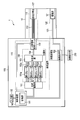
- FIG. 2 is a block diagram showing the main configuration of the endoscope system 1.
- FIG. 3 is a block diagram illustrating in detail the configuration of the endoscope system 1 according to the first embodiment.
- the endoscope system 1 includes an illuminating device 110 that irradiates an observation portion of an insertion object with illumination light, an image acquisition portion 120 that acquires an image of the observation portion, an input portion 130 to which an observation mode is input, A control device 140 that controls the illumination device 110 (a light source drive unit 111 and an incident area switching unit 160 described later) and an image acquisition unit 120 (an image processing unit 122 described later) according to the observation mode information, and the image display unit 200 described above. And have.
- the illumination device 110 and the image acquisition unit 120 are disposed across the system main body 100 from the endoscope 10.
- the input unit 130 and the control device 140 are arranged in the system main body 100.
- the illumination device 110 includes a light source unit 150, a light source driving unit 111, a bundle fiber 112, an incident area switching unit 160, and an illumination optical system 113.
- the light source unit 150, the light source driving unit 111, and the incident area switching unit 160 are arranged in the system main body 100.
- the bundle fiber 112 and the illumination optical system 113 are disposed in the endoscope 10.
- the light source unit 150 includes a plurality of laser light sources, for example, a first laser 151a, a second laser 151b, a third laser 151c, and a fourth laser 151d.
- the first laser 151a is a laser that emits violet laser light, and is, for example, a laser diode having a wavelength of 405 nm.
- the second laser 151b is a laser that emits blue laser light, and is, for example, a laser diode having a wavelength of 445 nm.
- the third laser 151c is a laser that emits green laser light, and is, for example, a laser diode having a wavelength of 515 nm.
- the fourth laser 151d is a laser that emits red laser light, and is, for example, a laser diode having a wavelength of 635 nm.
- the light source unit 150 further includes a first optical fiber 152a, a second optical fiber 152b, a third optical fiber 152c, and a fourth optical fiber 152d, an optical fiber combiner (optical multiplexing unit) 153, and an optical fiber 154. And have.
- the first to fourth optical fibers 152a to 152d and the optical fiber 154 are, for example, single-wire fibers having a core diameter of several ⁇ m to several hundred ⁇ m.
- the proximal ends of the first to fourth optical fibers 152a to 152d are optically connected to the first to fourth lasers 151a to 151d, respectively.
- the distal ends of the first to fourth optical fibers 152a to 152d are optically connected to the optical fiber combiner 153.
- the proximal end side of the optical fiber 154 is optically connected to the optical fiber combiner 153.
- the first to fourth optical fibers 152a to 152d guide the laser beams from the first to fourth lasers 151a to 151d, respectively.
- the optical fiber combiner 153 multiplexes the laser beams guided by the first to fourth optical fibers 152a to 152d.
- the optical fiber 154 guides the light combined by the optical fiber combiner 153 to the incident area switching unit 160.
- the laser beams emitted from the lasers 151a to 151d are converged and coupled to the optical fibers 152a to 152d between the lasers 151a to 151d and the first to fourth optical fibers 152a to 152d, respectively.
- a coupling lens (not shown) is arranged.
- the light source driving unit 111 is connected to the first to fourth lasers 151 a to 151 d of the light source unit 150. Moreover, the light source drive part 111 is connected to the control apparatus 140 so that communication is possible. The light source driving unit 111 turns on / off the first to fourth lasers 151a to 151d based on a control signal from the control device 140, a driving current, a driving method (continuous driving (CW), pulse driving, high frequency superposition, etc.) Etc. are driven and controlled.
- CW continuous driving
- pulse driving high frequency superposition, etc.
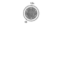
- Light guide member 4a and 4b are diagrams showing an incident end face (that is, a cross section perpendicular to the optical axis) of the bundle fiber 112 which is a light guide member in the first embodiment.
- the bundle fiber 112 is provided from the insertion portion 20 to the operation portion 30 of the endoscope 10.
- the bundle fiber 112 in this embodiment is formed by bundling tens to thousands of optical fibers 114.
- the incident ends of these optical fibers 114 are bonded with an adhesive and are in the same plane.
- the exit ends of these optical fibers are also connected by an adhesive and are in the same plane.
- the outer peripheral surface of the bundle fiber 112 is covered with a protective tube.
- the core diameter of each optical fiber 114 is several ⁇ m to several hundred ⁇ m.
- the diameter of the bundle fiber 112 is several hundred ⁇ m to several mm.
- the bundle fiber 112 in the present embodiment has a first light guide region 112a and a second light guide region 112b.
- the first light guide region 112a is a single optical fiber 114a positioned at the center of the bundle fiber 112, as shown in FIG. 4a.
- region 112b is all the optical fibers 114 which comprise the bundle fiber 112, as FIG. 4B shows. That is, the second light guide region 112b is the entire bundle fiber 112 including the first light guide region 112a.
- the optical axis of one optical fiber 114a positioned at the center of the bundle fiber 112 is the optical axis of the first light guide region
- the central axis for all the optical fibers constituting the bundle fiber 112 is the second Assuming the optical axis of the light guide region, the optical axis of the first light guide region and the optical axis of the second light guide region are substantially the same, and the optical axis directions thereof are the same.
- the first light guide region 112a has a smaller cross-sectional area than the second light guide region 112b.
- the cross-sectional area of the light guide region is small, light with the same phase is guided, and when the cross-sectional area of the light guide region is large, light with various phases is guided. Therefore, the laser light guided through the first light guide region 112a is light having a uniform phase, and has greater spatial coherence than the laser light guided through the second light guide region 112b.
- Spatial coherence is a quantity representing the uniformity of the phase of the wavefront and the coherence of light at different points on the wavefront.
- the first light guide region 112a and the second light guide region 112b have different light guide characteristics with respect to the laser light.
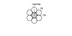
- FIG. 5 is an enlarged cross-sectional view of the incident end face in the vicinity of the first light guide region 112a of the bundle fiber 112 in the first embodiment.
- One optical fiber 114a corresponding to the first light guide region 112a is covered with a coating 115 which is a disconnection preventing member so as to be less likely to be broken than other optical fibers constituting the bundle fiber 112.
- a coating 115 is formed on one optical fiber 114a corresponding to the first light guide region 112a, and a nylon coating is formed on the other optical fibers.
- the coating of one optical fiber 114a corresponding to the first light guide region 112a and the coating of another optical fiber may be formed of the same material.
- the coating of one optical fiber 114a corresponding to the optical region 112a is made thicker than the coatings of other optical fibers.
- a heat generation reducing unit 116 for reducing heat generation is provided around the incident end of the optical fiber 114a corresponding to the first light guide region 112a.
- the heat generation reducing unit 116 is formed, for example, by mixing a heat conductive member (a heat conductive wire, a heat conductive filler, or the like) with an adhesive or soldering optical fibers together.
- the number of optical fibers 114a positioned at the center of the bundle fiber 112 corresponding to the first light guide region 112a is not limited to one, and may be plural. However, the number of optical fibers corresponding to the first light guide region 112a is smaller than the number of optical fibers corresponding to the second light guide region 112b, and the laser light that guides the first light guide region 112a is It is assumed that the spatial coherence is larger than that of the laser light guided through the second light guide region 112b.
- the endoscope system 1 has a plurality of observation modes for observing the observed portion using light having different optical characteristics.
- the endoscope system 1 has three observation modes: a speckle observation mode, a white light observation mode, and a special light observation mode.
- an observation mode (observation mode information) is input by the user.
- the input unit 130 is communicably connected to the control device 140, and the input observation mode information is output to the control device 140.
- the speckle observation mode is an observation mode in which the observed portion is analyzed based on speckle generated in the observed portion when the illumination device 110 is irradiated with laser light by the illumination device 110.
- information such as the movement and shape of the observed portion can be obtained by speckle.
- a living tissue is observed based on speckles generated when violet laser light is irradiated from the first laser 151a. Since the purple laser light is strongly scattered near the surface of the living tissue, information on the surface of the living tissue can be obtained mainly.
- the white light observation mode is an observation mode in which a portion to be observed is observed with white light from the illumination device 110.
- the white light in this embodiment is generated by mixing the red / green / blue laser light from the second laser 151b, the third laser 151c, and the fourth laser 151d.
- Special light observation mode emphasizes a specific observation target by irradiating light (special light) with a spectrum different from that of normal white light using characteristics such as light absorption, reflection, and scattering of the specific observation target. This is the observation mode to be displayed.
- a living tissue is observed using mixed light of violet laser light from the first laser 151a and green laser light from the third laser 151c as special light.
- Violet laser light has the property of being strongly absorbed by hemoglobin in capillaries near the surface of living tissue.
- the green laser light has a property of being strongly absorbed by hemoglobin in a thick blood vessel deep in a living tissue. Because of these properties, when a predetermined image processing is performed on a biological tissue imaged by irradiating special light, the contrast between the capillary and the thick blood vessel can be enhanced and observed.
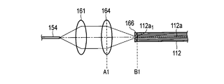
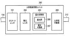
- FIG. 6 is a diagram schematically showing the incident region switching unit 160 in the first embodiment.
- FIG. 7 a is a schematic diagram of the incident region switching unit 160 in the speckle observation mode.
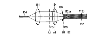
- FIG. 7B is a schematic diagram of the incident region switching unit 160 in the white light observation mode and the special light observation mode.
- the incident area switching unit 160 includes a collimator lens 161, a condensing position switching unit 162, and a light shielding switching unit 163. As shown in FIGS. 2 and 3, the incident region switching unit 160 is connected to the control device 140 so as to be communicable.
- the condensing position switching unit 162 includes a condensing lens 164 and a condensing lens movable unit 165.
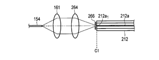
- the collimating lens 161 converts the laser light emitted from the optical fiber 154 of the light source unit 150 into parallel light.
- the condensing lens movable unit 165 includes, for example, a holding member that holds the condensing lens 164, a guide member that guides movement of the holding member, and an electric actuator that supplies power for moving the holding member. .
- the condensing lens 164 can be moved in the optical axis direction by driving the actuator of the condensing lens movable unit 165 and moving the holding member along the guide member, for example, the condensing lens on the optical axis. The position can be switched. The position of the condensing lens 164 in the optical axis direction is controlled by driving the condensing lens movable unit 165 by a control signal from the control device 140.
- the laser light that has passed through the condensing lens 164 is the first on the incident end face of the bundle fiber 112. Is incident on the incident region 112a1.
- the first incident region 112a1 is an incident end surface when the laser light is guided by the first light guide region 112a in the bundle fiber 112, that is, the optical fiber 114a positioned at the center of the bundle fiber 112.
- the first incident region 112a1 just includes the incident end face of the optical fiber 114a located at the center of the bundle fiber 112 (see FIG. 4a).
- the condensing position B1 of the light that has passed through the condensing lens 164 is in the first incident region 112a1 on the optical axis.
- the condensing lens 164 when the condensing lens 164 is arranged at the position A2 on the optical axis by the control device 140, the laser light that has passed through the condensing lens 164 is incident on the incident end face of the bundle fiber 112.
- the light enters the second incident region 112b1.
- the second incident region 112b1 is an incident end surface when the laser light is guided by the second light guiding region 112b in the bundle fiber 112, that is, all the optical fibers 114 constituting the bundle fiber 112.
- the second incident region 112b1 includes the incident end faces of all the optical fibers 114 constituting the bundle fiber 112 (see FIG. 4b).
- the condensing position B2 of the light that has passed through the condensing lens 164 is located on the tip side of the incident end so as to enter the bundle fiber 112 at the second incident region 112b1.
- FIG. 8a is a diagram showing the light shielding portion 166 and the first incident region 112a1 in the speckle observation mode.
- FIG. 8B is a diagram illustrating the light shielding unit 166 and the second incident region 112b1 in the white light observation mode and the special light observation mode.
- the light shielding switching unit 163 applies light to the region other than the first incident region 112a1 so that the light that has passed through the condenser lens 164 is incident on the first incident region 112a1 and is not incident on any region other than the first incident region 112a1.
- FIG. 8a light shielding state where light is shielded
- FIG. 8b non-light shielding state where light is not shielded
- the light shielding switching unit 163 includes a light shielding unit 166 and a light shielding movable unit 167.
- the light shielding part 166 is a disk-shaped member having a central opening, and is disposed in front of the incident end face of the bundle fiber 112.
- the light shielding unit 166 covers the incident end face of the bundle fiber 112 and can shield the light, and only light that has passed through the central opening reaches the incident end face.
- the light shielding movable portion 167 is an electric actuator for switching the size of the diameter of the central opening of the light shielding portion 166, for example.
- the range in which the light shielding portion 166 covers the incident end face of the bundle fiber 112 is controlled by driving the light shielding movable portion 167 by a control signal from the control device 140.
- the switching of the operation of the light shielding unit 166 is controlled in conjunction with the switching between the position A1 and the position A2 of the condenser lens 164, that is, in conjunction with the driving of the condenser lens movable unit 165 by a control signal from the control device 140. Is done.
- the condensing position B2 is positioned closer to the tip side than the incident end of the bundle fiber 112 in order to allow the laser light to enter the second incident region 112b1, but the condensing position B2 is set to the bundle fiber 112. It may be positioned closer to the light source than the incident end.
- the incident region switching unit 160 may have a configuration other than the configuration in which the condensing lens 164 is moved on the optical axis as long as the condensing positions B1 and B2 can be switched on the optical axis.
- a variable focus lens or a lens turret including a plurality of lenses having different optical characteristics may be used, and not only the condenser lens 164 but also the exit end of the optical fiber 154 and the collimator lens 161 are moved together. You may let them.
- the condensing position switching unit 162 and the light shielding switching unit 163 are used together, but only the position switching of the condensing lens 164 by the condensing position switching unit 162, or The incident region may be switched using only the switching of the light shielding range of the light shielding unit 166 by the light shielding switching unit 163. Note that when only the light shielding switching unit 163 is used, the condenser lens 164 is fixed at the position A2.
- the illumination optical system 113 is a lens (lens group) that converts the laser light guided by the bundle fiber 112 into a desired light distribution.
- the laser light whose light distribution has been converted by the illumination optical system 113 is emitted from an illumination window 117 provided at the distal end of the distal end hard portion 21 of the insertion portion 20 of the endoscope 10.
- the laser light guided by the first light guide region 112 a and the laser light guided by the second light guide region 112 b of the bundle fiber 112 are irradiated from the same illumination window 117.
- the image acquisition unit 120 includes an imaging unit 121 arranged in the insertion unit 20 of the endoscope 10 and an image processing unit 122 arranged in the system main body 100.
- the imaging unit 121 and the image processing unit 122 are connected via an imaging cable 123 that extends from the insertion unit 20 through the operation unit 30.
- the imaging unit 121 includes an observation optical system including an objective lens, and an imaging element that forms an optical image obtained from the observation optical system and converts it into an electrical signal.
- the imaging unit 121 captures reflected light from the observed portion using an observation optical system and performs imaging using an imaging element.
- the image sensor is, for example, a CCD imager, a CMOS imager, or the like.
- the image processing unit 122 performs image processing on the reflected light image acquired by the imaging unit 121.
- the image processing unit 122 is communicably connected to the control device 140.
- the control device 140 controls image processing by the image processing unit 122.
- the control device 140 receives the observation mode information input to the input unit 130 and controls the light source driving unit 111, the incident region switching unit 160, and the image processing unit 122 (hereinafter referred to as a control target unit). .
- the control device 140 has a storage unit 141.
- the storage unit 141 stores a control table on how to control the control target unit according to the observation mode.
- the control device 140 controls the control target unit based on the control table stored in the storage unit 141.
- Control in the speckle observation mode (control table 1) is as follows. Control table 1
- the light source driver 111 turns on the first laser 151a (purple laser light).
- the condensing position switching unit 162 of the incident region switching unit 160 causes the condensing lens movable unit 165 to place the condensing lens 164 at the position A1.
- the light shielding switching unit 163 shields the region other than the first incident region 112a1 by the light shielding unit 166 by using the light shielding movable unit 167.
- the image processing unit 122 performs known image processing for speckle observation.
- the control (control table 2) in the white light observation mode is as follows.
- Control table 2 The light source driver 111 turns on the second laser 151b (blue laser light), the third laser 151c (green laser light), and the fourth laser 151d (red laser light).
- the condensing position switching unit 162 of the incident region switching unit 160 causes the condensing lens movable unit 165 to place the condensing lens 164 at the position A2.
- the light shielding switching unit 163 does not perform light shielding by the light shielding unit 166.
- the image processing unit 122 performs known image processing suitable for white light by mixing the second to fourth lasers 151b to 151d.
- the control (control table 3) in the special light observation mode is as follows. Control table 3
- the light source driver 111 turns on the first laser 151a (purple laser light) and the third laser 151c (green laser light).
- the condensing position switching unit 162 of the incident region switching unit 160 causes the condensing lens movable unit 165 to place the condensing lens 164 at the position A2.
- the light shielding switching unit 163 does not perform light shielding by the light shielding unit 166.
- the image processing unit 122 performs known image processing suitable for special light observation.
- the image display unit 200 is communicably connected to the image acquisition unit 120 of the system main body 100.
- the image display unit 200 is, for example, a liquid crystal display, and displays the observed image generated by the image acquisition unit 120, observation mode information, and the like.
- the input unit 130 transmits information indicating that the speckle observation mode is input (input mode information) to the control device 140.
- the control device 140 controls the control target unit based on the control table 1 of the storage unit 141.
- the light source driving unit 111 turns on the first laser 151a.
- the violet laser light emitted from the first laser 151 a is incident on the first optical fiber 152 a, guided through the optical fiber combiner 153 and the optical fiber 154, and emitted from the emission end of the optical fiber 154.
- the emitted violet laser light is converted into parallel light by the collimating lens 161 of the incident area switching unit 160 and then condensed by the condenser lens 164 disposed at the position A1.
- the diameter of the central opening of the light shielding part 166 is substantially the same as the diameter of the first incident region 112a1. Therefore, the second incident region 112b1 is shielded by the light shielding switching unit 163, and the violet laser light condensed by the condenser lens 164 at the position A1 is incident on the first incident region 112a1 on the incident end surface of the bundle fiber 112. Then, the light is guided by the optical fiber 114a (first light guide region 112a) located at the center of the bundle fiber 112.
- the guided violet laser light is converted into a desired light distribution by the illumination optical system 113 and then irradiated to the observed portion from the illumination window 117.
- the violet laser light is guided by the single optical fiber 114a and irradiated to the observed portion while having high spatial coherence, so that speckle occurs in the observed portion.
- the reflected light image of the light irradiated on the observed part is picked up by the image pickup part 121.
- the reflected light image acquired by the imaging unit 121 is transmitted to the image processing unit 122.
- the image processing unit 122 performs predetermined (known) image processing for analyzing the observed part (living tissue) by speckle under the control of the control device 140, and generates an observed part image.
- the observed portion image generated by the image processing unit 122 is displayed on the image display unit 200.
- the input unit 130 transmits information indicating that the white light observation mode is input (input mode information) to the control device 140.
- the control device 140 controls the control target unit based on the control table 2 of the storage unit 141.
- the light source driving unit 111 turns on the second to fourth lasers 151b to 151d.
- the red / green / blue laser beams emitted from the second to fourth lasers 151b to 151d are respectively incident on the second to fourth optical fibers 152b to 152d and then multiplexed by the optical fiber combiner 153. It becomes white light. Then, white light guides the optical fiber 154 and is emitted from the exit end of the optical fiber 154.
- the emitted white light is converted into parallel light by the collimating lens 161 of the incident area switching unit 160 and then condensed by the condenser lens 164 disposed at the position A2 under the control of the control device 140.
- the white light condensed by the condenser lens 164 at the position A2 is incident on the second incident region 112b1 at the incident end of the bundle fiber 112, and all the optical fibers 114 (second guides) constituting the bundle fiber 112 are obtained.
- Light is guided by the light region 112b). Since the diameter of the central opening of the light shielding part 166 is equal to or larger than the diameter of the second incident region 112b1, light shielding by the light shielding switching part 163 is not performed.
- the guided white light is converted into a desired light distribution by the illumination optical system 113 and then irradiated from the illumination window 117 to the observed portion.
- the white light is guided by tens to thousands of optical fibers 114, and the spatial coherence is reduced and irradiated to the observed portion. Therefore, speckle is reduced in the observed portion.
- the reflected light image of the light irradiated on the observed part is picked up by the image pickup part 121.
- the reflected light image acquired by the imaging unit 121 is transmitted to the image processing unit 122.
- the image processing unit 122 performs predetermined (known) image processing suitable for white light by a mixture of red / green / blue lasers, and generates an observed portion image.
- the observed portion image generated by the image processing unit 122 is displayed on the image display unit 200.
- the input unit 130 transmits information indicating that the special light observation mode is input (input mode information) to the control device 140.
- the control device 140 controls the control target unit based on the control table 3 of the storage unit 141.
- the light source driving unit 111 turns on the first laser 151a and the third laser 151c.
- the violet / green laser beams emitted from the first laser 151a and the third laser 151c are incident on the first optical fiber 152a and the third optical fiber 152c, respectively, and then multiplexed by the optical fiber combiner 153. Is done. Then, the combined special light is guided through the optical fiber 154 and emitted from the output end of the optical fiber 154.
- the emitted special light is converted into parallel light by the collimating lens 161 of the incident area switching unit 160 and then condensed by the condenser lens 164 disposed at the position A2.
- the special light condensed by the condenser lens 164 at the position A2 is incident on the second incident region 112b1 at the incident end of the bundle fiber 112, and all the optical fibers (second light guides) constituting the bundle fiber 112 are obtained. Guided by region 112b). Since the diameter of the central opening of the light shielding part 166 is equal to or larger than the diameter of the second incident region 112b1, light shielding by the light shielding switching part 163 is not performed.
- the special light guided is converted into a desired light distribution by the illumination optical system 113 and then irradiated from the illumination window 117 to the observed portion.
- the special light is guided by tens to thousands of optical fibers 114, and the spatial coherence is reduced and irradiated to the observed portion. Therefore, speckle is reduced in the observed portion.
- the reflected light image of the light irradiated on the observed part is picked up by the image pickup part 121.
- the reflected light image acquired by the imaging unit 121 is transmitted to the image processing unit 122.
- the purple laser light is strongly absorbed by hemoglobin in the capillary near the surface of the observed portion (living tissue), and the green laser light is hemoglobin in the thick blood vessel in the deep portion of the observed portion (living tissue).
- image processing that enhances the contrast between capillaries and thick blood vessels (known) is performed to generate an observed portion image.
- the observed portion image generated by the image processing unit 122 is displayed on the image display unit 200.
- the laser light guides the first light guide region 112a of the bundle fiber 112 in the speckle observation mode, and the spec.
- the laser light guides the second light guide region 112b of the bundle fiber 112.
- the treatment instrument insertion port 33 treatment instrument insertion channel of the endoscope 10 can be used. It is possible to provide an endoscope system that can perform observation with good operability without using (). Since the bundle fiber 112 is fixedly disposed with respect to the endoscope 10, a more stable operation is possible than when the optical probe is inserted from the treatment instrument insertion port 33.
- the laser light in the speckle observation mode, is guided through the first light guide region 112a having a small cross-sectional area, so that the laser light is guided with a high spatial coherence. Accordingly, speckles are sufficiently generated in the observed portion, and conventional speckle observation is possible.
- the laser light is guided through the second light guide region 112b having a large cross-sectional area, so that the spatial coherence of the laser light is reduced and speckle is reduced. Therefore, it is possible to perform observation while preventing deterioration of the image quality of the observed portion image due to unnecessary speckle in an observation mode other than the speckle observation mode.
- control device 140 interlocks the light source driving unit 111, the image processing unit 122, and the incident area switching unit 160 based on the control table of the storage unit 141 according to the observation mode information input to the input unit 130. By controlling, it is possible to efficiently switch the operation of the endoscope system.
- the incident region switching unit 160 by switching the laser beam condensing positions B1 and B2 by the incident region switching unit 160, it is possible to switch the laser light incident region with respect to the light guide member and to switch the light guide region for guiding the laser light.
- the light guide that guides the laser light by switching the condensing positions B1 and B2 of the laser light in the optical axis direction.
- the area can be switched efficiently.
- the laser beam in the speckle observation mode, is incident on the first incident region and is not incident on the incident region other than the first incident region.
- the light guiding area for guiding the laser beam can be simplified without switching the optical system. Can be switched.
- the disconnection preventing member can prevent disconnection of the optical fiber included in the first light guide region of the bundle fiber, and can prevent a problem that illumination light is not irradiated in the speckle observation mode.
- the heat generation reducing unit when the laser light is locally irradiated to the adhesive or the like around the optical fiber included in the first light guide region of the bundle fiber by the heat generation reducing unit, the heat generation is reduced and problems such as scorching are reduced. Can be prevented.
- an optical multiplexing unit that multiplexes a plurality of laser beams into a single light beam, when different laser beams are used in the speckle observation mode and other observation modes, the same A light guide member and an illumination window can be used.
- the laser light used in the speckle observation mode by using the same light guide member and illumination window in the speckle observation mode and the observation mode other than the speckle observation mode, the laser light used in the speckle observation mode, and other than that When the characteristics of the laser light used in the observation mode are the same, the same light source can be used. Therefore, space saving and cost reduction of the endoscope system can be achieved.
- white light can be observed while giving the effect of the laser light by using white light of three colors of red / green / blue laser light. Further, in the special light observation mode, by using purple / green laser light, the contrast between the capillary blood vessel on the surface of the living tissue and the deep blood vessel can be emphasized for observation.
- the light source unit 150 is not limited to the laser light source, and may have a light source having coherent properties that causes speckles in the observed portion.
- a light source having coherent properties that causes speckles in the observed portion For example, an LED or the like may be used.
- the optical multiplexing unit 153 is not limited to the optical fiber combiner, and may be an optical multiplexer that uses a spatial optical system.
- the endoscope system 1 may have an observation mode other than the white light observation mode and the special light observation mode.
- a mode for irradiating white light of different colors a mode for performing other known special light observations for highlighting the observed part, or a fluorescence generated when the observed part or drug is irradiated with excitation light is observed. It may have a fluorescence observation mode.
- the plurality of observation modes may have a narrow light distribution angle mode instead of the speckle observation mode.
- the narrow light distribution angle mode is used in addition to the other observation modes.
- FIG. 9a is a schematic diagram showing the bundle fiber 112 and the illumination optical system 113 in the narrow light distribution angle mode.
- FIG. 9B is a schematic diagram showing the bundle fiber 112 and the illumination optical system 113 in the white light observation mode and the special light observation mode.
- the illumination optical system 113 has different light distribution conversion characteristics for the laser light guided by the first light guide region 112a and light distribution conversion characteristics for the laser light guided by the second light guide region 112b. Designed optically.
- the control device 140 When the narrow light distribution angle mode is input to the input unit 130, the control device 140 enters the first incident region 112a1 of the bundle fiber 112 so that the laser beam is incident and guides the first light guiding region 112a.
- the area switching unit 160 is controlled.
- the light distribution angle of the illumination light In the narrow light distribution angle mode, the light distribution angle of the illumination light is narrower than in observation modes other than the narrow light distribution angle mode. Therefore, in this modification, it is possible to simply switch the distribution of illumination light simply by switching the light guide region in the light guide member.
- the light guiding member that guides the laser light from the incident region switching unit 260 to the illumination optical system 113 is the double clad fiber 212.
- the incident area switching unit 260 includes a condensing lens 264 and an incident end movable unit 268 instead of the condensing position switching unit 162. Further, the control table in the control device 140 is changed.
- FIGS. 10, 11a, and 11b are cross-sectional views of a double-clad fiber 212 that is a light guide member in the second embodiment.
- the double clad fiber 212 has a central core 218a, a first clad 218b covering the outer peripheral surface of the core 218a, and a second clad 218c covering the outer peripheral surface of the first clad 218b.
- the refractive index of the core 218a is n1
- the refractive index of the first cladding 218b is n2
- the refractive index of the second cladding 218c is n3, n1>n2> n3.
- the double clad fiber 212 has a configuration in which three base materials having different refractive indexes are distributed concentrically around the optical axis.
- the diameter of the core 218a is several ⁇ m to several tens of ⁇ m.
- the diameters of the first cladding 218b and the second cladding 218c are several tens of ⁇ m to several hundreds of ⁇ m.
- the first light guide region 212a is a core 218a, and as shown in FIG. 11b, the second light guide region 212b. Are the core 218a and the first cladding 218b.
- the first light guide region 212a has a smaller cross-sectional area than the second light guide region 212b.
- the laser light that guides the first light guide region 212a having a small cross-sectional area is light having a uniform phase, and is more than the laser light that guides the second light guide region 212b having a large cross-sectional area. Has a large spatial coherence.
- the laser light incident on the first light guide region 212a is guided while repeating total reflection at the boundary between the core 218a and the first clad 218b.
- the laser light incident on the second light guide region 212b is guided while repeating total reflection at the boundary between the first clad 218b and the second clad 218c.
- FIG. 12 is a diagram schematically showing the incident region switching unit 260 in the second embodiment.
- FIG. 13 a is a schematic diagram of the incident region switching unit 260 in the speckle observation mode.
- FIG. 13B is a schematic diagram of the incident region switching unit 260 in the white light observation mode and the special light observation mode.
- the incident area switching unit 260 includes a collimator lens 161, a condenser lens 264, a light shielding switching unit 263, and an incident end movable unit 268.
- the incident area switching unit 260 is connected to the control device 140 so as to be communicable.
- the light shielding switching unit 263 includes a light shielding unit 266 and a light shielding movable unit 267 as in the first embodiment.
- the exit end of the optical fiber 154, the collimating lens 161, and the condenser lens 264 are fixed.
- the incident end movable part 268 moves the incident end of the double clad fiber 212 in the optical axis direction.
- the incident end movable portion 268 includes, for example, a holding member that holds the incident end of the double clad fiber 212, a guide member that guides the movement of the holding member, and an electric actuator that supplies power for moving the holding member. ing.
- the double clad fiber 212 is movable in the optical axis direction by driving the actuator of the incident end movable portion 268 and moving the holding member along the guide member. Further, the light shielding switching unit 263 is also held with the double clad fiber 212 and moves together with the double clad fiber 212.
- the incident region of the laser beam with respect to the double clad fiber 212 is switched by switching the position of the incident end of the double clad fiber 212 with respect to the optical axis direction by the incident end movable portion 268 of the incident region switching unit 260.
- the incident end movable part 268 is controlled by a control signal from the control device 140.
- the laser light that has passed through the condenser lens 264 enters the double clad fiber 212.
- the light enters the first incident region 212a1 on the end face.
- the first incident region 212a1 is an incident end surface when the laser light is guided by the first light guide region 212a in the double clad fiber 212, that is, the core 218a of the double clad fiber 212.
- the first incident region 212a1 just includes the incident end face of the core 218a of the double clad fiber 212 (see FIG. 11a).
- the laser light that has passed through the condensing lens 264 is double clad fiber 212.
- the second incident region 212b1 is an incident end surface when the laser light is guided by the second light guide region 212b in the double clad fiber 212, that is, the core 218a and the first clad 218b of the double clad fiber 212.
- the second incident region 212b1 just includes the incident end faces of the core 218a and the first cladding 218b of the double clad fiber 212 (see FIG. 11b).
- Control table Of the control tables stored in the storage unit 141 of the control device 140 in the second embodiment, the control of the light source driving unit 111 and the image processing unit 122 is the same as that in the first embodiment. Only the changes related to the control of the incident end movable portion 268 and the light shielding switching portion 263 of the region switching unit 260 are shown.
- the incident end movable unit 268 of the incident region switching unit 260 places the incident end of the double clad fiber 212 at the position C1.
- the light shielding switching unit 263 uses the light shielding movable unit 267 to shield the region other than the first incident region 212a1 with the light shielding unit 266.
- the incident end movable unit 268 of the incident region switching unit 260 arranges the incident end of the double clad fiber 212 at the position C2.
- the light shielding switching unit 263 does not perform light shielding by the light shielding unit 266.
- the incident end movable unit 268 of the incident region switching unit 260 places the incident end of the double clad fiber 212 at the position C2.
- the light shielding switching unit 263 does not perform light shielding by the light shielding unit 266.
- This embodiment can also achieve the same effects as those of the first embodiment.
- the laser light is guided by switching the incident end position of the light guide member in the optical axis direction.
- the light guide region to be switched can be switched efficiently.
- the light guide member by using a double clad fiber as the light guide member, it is possible to switch the light guide region that guides the laser light with a single optical fiber.
- the bundle fiber 112 may be used instead of the double clad fiber 212. Conversely, a double clad fiber 212 may be used instead of the bundle fiber 112 in the first embodiment.
- the light guide member that guides the laser light from the incident region switching unit 360 to the illumination optical system 113 is a bundle fiber 312 composed of a single mode fiber 318 and a multimode fiber 319. Further, the exit end movable portion 368 of the incident area switching unit 360 can switch the light collection position in a direction perpendicular to the optical axis direction of the light guide member. Further, the control table in the control device 140 is changed.
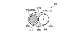
- FIG. 14 is a diagram illustrating an incident end face of a bundle fiber 312 that is a light guide member in the third embodiment.
- the bundle fiber 312 is composed of a single mode fiber 318 and a multimode fiber 319. The incident ends of these fibers are bonded with an adhesive and are in the same plane. The exit ends of these optical fibers are also connected by an adhesive and are in the same plane.
- the outer peripheral surface of the bundle fiber 312 is covered with a protective tube.
- the core diameter of the multimode fiber is several tens of ⁇ m to several hundreds of ⁇ m.
- the core diameter of the single mode fiber is about 10 ⁇ m.
- Each cladding diameter is several tens to several hundreds of ⁇ m.
- the single mode fiber 318 has a core 318a and a clad 318b.
- the multimode fiber 319 has a core 319a and a clad 319b.
- the first light guide region 312a is the core 318a of the single mode fiber 318
- the second light guide region 312b is a multimode fiber. 319 core 319a.
- the optical axis of the single mode fiber 318 (first light guide region 312a) and the optical axis of the multimode fiber 319 (second light guide region 312b) are parallel at least at the incident end face.
- the first light guide region 312a has a smaller cross-sectional area than the second light guide region 312b.
- the laser light that guides the first light guide region 312a having a small cross-sectional area is light having a uniform phase, and is more than the laser light that guides the second light guide region 312b having a large cross-sectional area. Has a large spatial coherence.
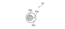
- a multi-core fiber 372 as shown in FIG. 15 may be adopted instead of the bundle fiber 312 composed of two single-mode fibers and multi-mode fibers.
- the multi-core fiber 372 includes a first core 372a and a second core 372b that are independent from each other, and a clad 372c that covers the outer peripheral surfaces of the first core 372a and the second core 372b.
- a single multi-core fiber having at least two cores independent of the same cladding may be used.
- the first light guide region 312a has a smaller cross-sectional area than the second light guide region 312b, and the laser light that guides the first light guide region is the second light guide region.
- the spatial coherence is made larger than the laser light that guides the light. Even when a multi-core fiber is used, the configuration of the incident region switching unit 360 is the same.
- FIG. 16 is a diagram schematically illustrating an incident region switching unit 360 according to the third embodiment.
- FIG. 17 a is a schematic diagram of the incident region switching unit 360 in the speckle observation mode.
- FIG. 17B is a schematic diagram of the incident region switching unit 360 in the white light observation mode and the special light observation mode.
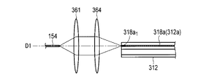
- the incident area switching unit 360 includes a first lens 361, a second lens 364, and a condensing position switching unit 362.
- the incident region switching unit 360 is connected to the control device 140 so as to be communicable. In this embodiment, the light shielding switching unit is not used.
- the condensing position switching unit 362 moves the exit end of the optical fiber 154 of the light source unit 150 in a direction perpendicular to the optical axis direction of the first light guide region and the second light guide region.
- a movable portion 368 is provided.
- the first lens 361 and the second lens 364 are condensing optical systems that can switch laser light to a desired incident region.
- the incident ends of the first lens 361, the second lens 364, and the bundle fiber 312 are fixed.
- the exit end movable unit 368 moves the exit end of the optical fiber 154 of the light source unit 150 in a direction perpendicular to the optical axis of the bundle fiber 312.
- the emitting end movable portion 368 includes, for example, a holding member that holds the emitting end of the optical fiber 154, a guide member that guides the movement of the holding member, and an electric actuator that supplies power for moving the holding member. Yes.
- the optical fiber 154 is movable in a direction perpendicular to the optical axis direction by driving the actuator of the emitting end movable portion 368 and moving the holding member along the guide member.
- the laser beam is incident on the bundle fiber 312 by switching the position in the direction perpendicular to the optical axis direction of the output end of the optical fiber 154 of the light source unit 150 by the output end movable unit 368 of the incident region switching unit 360. Switch areas.
- the exit end movable portion 368 is controlled by a control signal from the control device 140.
- the laser light is incident on the incident end face of the bundle fiber 312.
- the light enters the first incident region 318a1.
- the first incident region 318a1 is an incident end surface when the laser light is guided by the first light guiding region 312a in the bundle fiber 312, that is, the core 318a of the single mode fiber 318.
- the first incident region 318a1 just includes the incident end face of the core 318a of the single mode fiber 318.
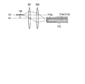
- the laser light is incident on the bundle fiber 312.
- the light enters the second incident region 319a1 at the end face.
- the second incident region 319a1 is an incident end surface when the laser light is guided by the second light guiding region 312b in the bundle fiber 312, that is, the core 319a of the multimode fiber 319.
- the second incident region 319a1 just includes the incident end face of the core 319a of the multimode fiber 319.
- the first lens 361 and the second lens 364 are designed so that the condensing position can be switched as described above.
- the laser light incident area on the bundle fiber 312 is switched by switching the position of the emission end of the optical fiber 154 in a direction perpendicular to the optical axis of the bundle fiber 312.
- the incident end of the laser beam to the bundle fiber 312 may be switched using a movable condensing optical system or a movable mirror, or the incident end of the bundle fiber 312 may be perpendicular to the optical axis.
- the direction may be switched.
- Control table Among the control tables stored in the storage unit 141 of the control device 140 in the third embodiment, the control of the light source driving unit 111 and the image processing unit 122 is the same as that in the first embodiment, and hence the incident will be described below. Only the changes relating to the control of the exit end movable portion 368 of the region switching unit 360 are shown.
- This embodiment can also achieve the same effects as those of the first embodiment.
- the laser light is guided by switching the condensing position of the laser light with respect to the direction perpendicular to the optical axis.
- the light guide region can be switched efficiently.
- the laser light is guided to a light guide member having a plurality of light guide regions that are not coaxial by switching the emission end of the optical fiber 154 that is a light guide member in a direction perpendicular to the optical axis direction.
- the light guide region can be switched.
- the light guide region for guiding the laser light can be switched with a thin light guide member. Can do.
- the position of the incident end of the bundle fiber 312 is fixed, and the position of the exit end of the optical fiber 154 is moved in the direction perpendicular to the optical axis by the exit end movable portion 368.
- the position of the incident end of the bundle fiber 312 may also be movable in a direction perpendicular to the optical axis by using the movable incident end movable portion 268.
- imaging cable 130 ... input unit, 140 ... control device, 141 DESCRIPTION OF SYMBOLS ... Memory
Abstract
The present invention is an endoscopic system with multiple observation modes for observing an area to be observed using light with mutually differing optical characteristics. The endoscopic system is equipped with: an endoscope with an inserted section that is provided with an illumination window; a light-guiding member that is disposed inside the inserted section and has an entrance end where light enters and multiple light-guiding regions for which the light-guiding characteristics with respect to light differ from each other and the respective optical axis directions are equal and which guide light entering from the entrance end; and an entry region-switching unit for switching the light-guiding region for light-guiding by switching the region in the entrance end of the light-guiding member where light enters according to the observation mode. The light guided by the light-guiding member is irradiated as illumination light on the area to be observed from the same illumination window in all observation modes.
Description
本発明は、互いに異なる光学特性を有する光を用いて観察を行う複数の観察モードを有する内視鏡システムに関する。
The present invention relates to an endoscope system having a plurality of observation modes for performing observation using light having different optical characteristics.
レーザ光のようなコヒーレント性を有する光が対象物に照射されると、対象物の表面付近で散乱された光の位相が重なり合い、表面付近の状態を反映したスペックルと呼ばれる干渉パターンが生じる。近年、レーザ光を生体組織に照射した際に発生するこのようなスペックルに基づいて生体組織を分析する光プローブの開発が進められている。例えば、特許文献1には、スペックルに基づいて生体組織を光学的に分析するための光プローブが開示されている。このような光プローブは、例えば、内視鏡と共に使用することが想定されている。
When the object is irradiated with light having a coherent property such as laser light, the phases of the light scattered near the surface of the object overlap, and an interference pattern called speckle that reflects the state near the surface is generated. In recent years, development of an optical probe for analyzing a living tissue based on such speckles generated when the living tissue is irradiated with laser light has been advanced. For example, Patent Document 1 discloses an optical probe for optically analyzing a living tissue based on speckle. Such an optical probe is assumed to be used with, for example, an endoscope.
特許文献1に記載の光プローブが内視鏡と共に使用される場合、光プローブが内視鏡の処置具挿通口から処置具挿通チャンネルに挿入されると考えられる。しかしながら、光プローブが処置具挿通口から挿入される場合、光プローブは内視鏡に対して固定されない。それ故、光プローブの操作性が悪くなり、適切な観察をすることが難しくなる。また、処置具挿通口から処置具挿通チャンネルに光プローブを挿入してしまうと、挿入している間はここに他の処置具を挿通することができない。
When the optical probe described in Patent Document 1 is used with an endoscope, it is considered that the optical probe is inserted into the treatment instrument insertion channel from the treatment instrument insertion port of the endoscope. However, when the optical probe is inserted from the treatment instrument insertion port, the optical probe is not fixed to the endoscope. Therefore, the operability of the optical probe is deteriorated and it is difficult to perform appropriate observation. Further, if the optical probe is inserted into the treatment instrument insertion channel from the treatment instrument insertion port, another treatment instrument cannot be inserted here during the insertion.
そこで、本発明は、処置具挿通口(処置具挿通チャンネル)を用いることなく、操作性良く観察をすることができる、互いに異なる光学特性を有する光を用いて観察を行う複数の観察モードを有する内視鏡システムを提供することを目的とする。
Accordingly, the present invention has a plurality of observation modes in which observation can be performed with good operability without using a treatment instrument insertion port (treatment instrument insertion channel) and observation is performed using light having different optical characteristics. An object is to provide an endoscope system.
本発明の一実施形態は、互いに異なる光学特性を有する光を用いて被観察部の観察を行う複数の観察モードを有する内視鏡システムにおいて、照明窓が設けられた挿入部を有する内視鏡と、前記光が入射する入射端と、前記光に対する導光特性が互いに異なり、それぞれの光軸方向が等しく、前記入射端から入射した光を導光する複数の導光領域とを有し、前記挿入部内に配設される導光部材と、観察モードに応じて前記導光部材の前記入射端において光が入射する領域を切り替えることにより、前記複数の導光領域のうち前記入射した光を導光する導光領域を切り替える入射領域切替ユニットとを具備し、前記導光部材を導光された前記光は、各観察モードにおいて同一の前記照明窓から被観察部に照明光として照射される内視鏡システムである。
One embodiment of the present invention provides an endoscope having an insertion portion provided with an illumination window in an endoscope system having a plurality of observation modes for observing a portion to be observed using light having different optical characteristics. And an incident end where the light is incident, and a plurality of light guiding regions for guiding light incident from the incident end, wherein the light guide characteristics for the light are different from each other, the respective optical axis directions are equal, By switching a light guide member disposed in the insertion portion and a region where light enters at the incident end of the light guide member according to an observation mode, the incident light among the plurality of light guide regions is changed. An incident region switching unit that switches a light guide region that guides light, and the light guided through the light guide member is irradiated as illumination light to the observed portion from the same illumination window in each observation mode Endoscope system It is.
本発明によれば、処置具挿通口(処置具挿通チャンネル)を用いることなく、操作性良く観察をすることができる、互いに異なる光学特性を有する光を用いて観察を行う複数の観察モードを有する内視鏡システムを提供することができる。
According to the present invention, it is possible to perform observation with good operability without using a treatment instrument insertion port (treatment instrument insertion channel), and a plurality of observation modes for performing observation using light having different optical characteristics. An endoscope system can be provided.
[第1の実施形態]
本発明の第1の実施形態の内視鏡システム1について、図1乃至図9を参照して説明する。 [First Embodiment]
An endoscope system 1 according to a first embodiment of the present invention will be described with reference to FIGS. 1 to 9.
本発明の第1の実施形態の内視鏡システム1について、図1乃至図9を参照して説明する。 [First Embodiment]
An endoscope system 1 according to a first embodiment of the present invention will be described with reference to FIGS. 1 to 9.
(内視鏡システムの概要)
図1は、第1の実施形態の内視鏡システム1を概略的に示す図である。内視鏡システム1は、内視鏡10と、内視鏡10に接続される内視鏡システム本体(以下、システム本体と称する)100と、システム本体100に接続される画像表示部200とを有している。 (Overview of endoscope system)
FIG. 1 is a diagram schematically illustrating an endoscope system 1 according to the first embodiment. The endoscope system 1 includes anendoscope 10, an endoscope system main body (hereinafter referred to as a system main body) 100 connected to the endoscope 10, and an image display unit 200 connected to the system main body 100. Have.
図1は、第1の実施形態の内視鏡システム1を概略的に示す図である。内視鏡システム1は、内視鏡10と、内視鏡10に接続される内視鏡システム本体(以下、システム本体と称する)100と、システム本体100に接続される画像表示部200とを有している。 (Overview of endoscope system)
FIG. 1 is a diagram schematically illustrating an endoscope system 1 according to the first embodiment. The endoscope system 1 includes an
内視鏡10は、被挿入体に挿入される可撓性の挿入部20と、挿入部20の基端側に設けられた操作部30とを有している。挿入部20は、内視鏡先端側の細長い管状部分である。挿入部20は、先端硬質部21と、先端硬質部21の基端側に設けられた湾曲部22と、湾曲部22の基端側に設けられた可撓管部23とを有している。先端硬質部21には、照明レンズを含む照明光学系113、観察光学系と撮像素子とを含む撮像部121等が内蔵されている(図3参照)。湾曲部22は、操作部30を操作することにより所望の方向に湾曲する。可撓管部23は湾曲自在であり、例えば、被挿入体の湾曲形状に沿って湾曲する。
The endoscope 10 includes a flexible insertion portion 20 to be inserted into the insertion target, and an operation portion 30 provided on the proximal end side of the insertion portion 20. The insertion portion 20 is an elongated tubular portion on the distal end side of the endoscope. The insertion portion 20 has a distal end hard portion 21, a bending portion 22 provided on the proximal end side of the distal end hard portion 21, and a flexible tube portion 23 provided on the proximal end side of the bending portion 22. . The distal end hard portion 21 incorporates an illumination optical system 113 including an illumination lens, an imaging unit 121 including an observation optical system and an image sensor, and the like (see FIG. 3). The bending portion 22 is bent in a desired direction by operating the operation unit 30. The flexible tube portion 23 is bendable, for example, bends along the curved shape of the inserted object.
操作部30は、可撓管部23の基端側に設けられた本体部31と、本体部31の基端側に設けられた把持部32とを有している。本体部31には、処置具挿通口33が設けられており、処置具挿通口33から可撓管部23及び湾曲部22内を通って先端硬質部21に不図示の処置具挿通チャンネルが延びている。把持部32は、湾曲部22を湾曲操作するための湾曲操作ダイヤル34と、送気/送水、吸引及び撮影等をするためのスイッチ35とを有している。
The operation unit 30 includes a main body portion 31 provided on the proximal end side of the flexible tube portion 23 and a grip portion 32 provided on the proximal end side of the main body portion 31. The main body 31 is provided with a treatment instrument insertion port 33, and a treatment instrument insertion channel (not shown) extends from the treatment instrument insertion port 33 through the flexible tube portion 23 and the bending portion 22 to the distal end hard portion 21. ing. The grip portion 32 includes a bending operation dial 34 for bending the bending portion 22 and a switch 35 for air / water supply, suction, photographing, and the like.
挿入部20及び操作部30の内部には、先端が先端硬質部21の照明光学系113に接続された照明光用のバンドルファイバ112と、先端が先端硬質部21の撮像部121に接続された撮像素子用の電気配線(撮像ケーブル)123とが延びている(図3参照)。バンドルファイバ112及び撮像ケーブル123は、把持部32の基端側から側方に延出しているユニバーサルコード36に収容されている。ユニバーサルコード36の端部には接続コネクタ37が設けられている。接続コネクタ37は、システム本体100に接続される。
Inside the insertion unit 20 and the operation unit 30, the bundle fiber 112 for illumination light whose tip is connected to the illumination optical system 113 of the hard tip 21 and the tip are connected to the imaging unit 121 of the hard tip 21. Electrical wiring (imaging cable) 123 for the image sensor extends (see FIG. 3). The bundle fiber 112 and the imaging cable 123 are accommodated in a universal cord 36 that extends laterally from the proximal end side of the grip portion 32. A connection connector 37 is provided at the end of the universal cord 36. The connection connector 37 is connected to the system main body 100.
図2は、内視鏡システム1の主要な構成を示すブロック図である。図3は、第1の実施形態の内視鏡システム1の構成を詳細に示すブロック図である。内視鏡システム1は、被挿入体の被観察部に照明光を照射する照明装置110と、被観察部の画像を取得する画像取得部120と、観察モードが入力される入力部130と、観察モード情報に応じて照明装置110(後述する光源駆動部111及び入射領域切替ユニット160)及び画像取得部120(後述する画像処理部122)を制御する制御装置140と、上述の画像表示部200とを有している。照明装置110及び画像取得部120は、内視鏡10からシステム本体100にまたがって配置されている。入力部130及び制御装置140は、システム本体100に配置されている。
FIG. 2 is a block diagram showing the main configuration of the endoscope system 1. FIG. 3 is a block diagram illustrating in detail the configuration of the endoscope system 1 according to the first embodiment. The endoscope system 1 includes an illuminating device 110 that irradiates an observation portion of an insertion object with illumination light, an image acquisition portion 120 that acquires an image of the observation portion, an input portion 130 to which an observation mode is input, A control device 140 that controls the illumination device 110 (a light source drive unit 111 and an incident area switching unit 160 described later) and an image acquisition unit 120 (an image processing unit 122 described later) according to the observation mode information, and the image display unit 200 described above. And have. The illumination device 110 and the image acquisition unit 120 are disposed across the system main body 100 from the endoscope 10. The input unit 130 and the control device 140 are arranged in the system main body 100.
(照明装置)
照明装置110は、光源部150と、光源駆動部111と、バンドルファイバ112と、入射領域切替ユニット160と、照明光学系113とを有している。光源部150、光源駆動部111及び入射領域切替ユニット160は、システム本体100に配置されておいる。バンドルファイバ112及び照明光学系113は、上述したように、内視鏡10に配置されている。 (Lighting device)
Theillumination device 110 includes a light source unit 150, a light source driving unit 111, a bundle fiber 112, an incident area switching unit 160, and an illumination optical system 113. The light source unit 150, the light source driving unit 111, and the incident area switching unit 160 are arranged in the system main body 100. As described above, the bundle fiber 112 and the illumination optical system 113 are disposed in the endoscope 10.
照明装置110は、光源部150と、光源駆動部111と、バンドルファイバ112と、入射領域切替ユニット160と、照明光学系113とを有している。光源部150、光源駆動部111及び入射領域切替ユニット160は、システム本体100に配置されておいる。バンドルファイバ112及び照明光学系113は、上述したように、内視鏡10に配置されている。 (Lighting device)
The
(光源部)
光源部150は、複数のレーザ光源を、例えば、第1のレーザ151a、第2のレーザ151b、第3のレーザ151c及び第4のレーザ151dを有している。第1のレーザ151aは、紫色レーザ光を照射するレーザであり、例えば、波長405nmのレーザダイオードである。第2のレーザ151bは、青色レーザ光を照射するレーザであり、例えば、波長445nmのレーザダイオードである。第3のレーザ151cは、緑色レーザ光を照射するレーザであり、例えば、波長515nmのレーザダイオードである。第4のレーザ151dは、赤色レーザ光を照射するレーザであり、例えば、波長635nmのレーザダイオードである。 (Light source)
Thelight source unit 150 includes a plurality of laser light sources, for example, a first laser 151a, a second laser 151b, a third laser 151c, and a fourth laser 151d. The first laser 151a is a laser that emits violet laser light, and is, for example, a laser diode having a wavelength of 405 nm. The second laser 151b is a laser that emits blue laser light, and is, for example, a laser diode having a wavelength of 445 nm. The third laser 151c is a laser that emits green laser light, and is, for example, a laser diode having a wavelength of 515 nm. The fourth laser 151d is a laser that emits red laser light, and is, for example, a laser diode having a wavelength of 635 nm.
光源部150は、複数のレーザ光源を、例えば、第1のレーザ151a、第2のレーザ151b、第3のレーザ151c及び第4のレーザ151dを有している。第1のレーザ151aは、紫色レーザ光を照射するレーザであり、例えば、波長405nmのレーザダイオードである。第2のレーザ151bは、青色レーザ光を照射するレーザであり、例えば、波長445nmのレーザダイオードである。第3のレーザ151cは、緑色レーザ光を照射するレーザであり、例えば、波長515nmのレーザダイオードである。第4のレーザ151dは、赤色レーザ光を照射するレーザであり、例えば、波長635nmのレーザダイオードである。 (Light source)
The
光源部150は、さらに、第1の光ファイバ152a、第2の光ファイバ152b、第3の光ファイバ152c及び第4の光ファイバ152dと、光ファイバコンバイナ(光合波部)153と、光ファイバ154とを有している。第1~第4の光ファイバ152a~152d及び光ファイバ154は、例えば、コア径数μm~数百μmの単線ファイバである。第1~第4の光ファイバ152a~152dの基端側は、それぞれ、第1~第4のレーザ151a~151dに光学的に接続されている。第1~第4の光ファイバ152a~152dの先端側は、光ファイバコンバイナ153に光学的に接続されている。また、光ファイバコンバイナ153には、光ファイバ154の基端側が光学的に接続されている。
The light source unit 150 further includes a first optical fiber 152a, a second optical fiber 152b, a third optical fiber 152c, and a fourth optical fiber 152d, an optical fiber combiner (optical multiplexing unit) 153, and an optical fiber 154. And have. The first to fourth optical fibers 152a to 152d and the optical fiber 154 are, for example, single-wire fibers having a core diameter of several μm to several hundred μm. The proximal ends of the first to fourth optical fibers 152a to 152d are optically connected to the first to fourth lasers 151a to 151d, respectively. The distal ends of the first to fourth optical fibers 152a to 152d are optically connected to the optical fiber combiner 153. The proximal end side of the optical fiber 154 is optically connected to the optical fiber combiner 153.
第1~第4の光ファイバ152a~152dは、それぞれ、第1~第4のレーザ151a~151dからのレーザ光を導光する。光ファイバコンバイナ153は、第1~第4の光ファイバ152a~152dによって導光されたレーザ光を合波する。光ファイバ154は、光ファイバコンバイナ153によって合波された光を入射領域切替ユニット160に導光する。
The first to fourth optical fibers 152a to 152d guide the laser beams from the first to fourth lasers 151a to 151d, respectively. The optical fiber combiner 153 multiplexes the laser beams guided by the first to fourth optical fibers 152a to 152d. The optical fiber 154 guides the light combined by the optical fiber combiner 153 to the incident area switching unit 160.
なお、レーザ151a~151dと第1~第4の光ファイバ152a~152dとの間には、それぞれ、レーザ151a~151dから射出されたレーザ光を収束させて光ファイバ152a~152dに結合するための不図示の結合レンズが配置されている。
The laser beams emitted from the lasers 151a to 151d are converged and coupled to the optical fibers 152a to 152d between the lasers 151a to 151d and the first to fourth optical fibers 152a to 152d, respectively. A coupling lens (not shown) is arranged.
(光源駆動部)
光源駆動部111は、光源部150の第1~第4のレーザ151a~151dに接続されている。また、光源駆動部111は、制御装置140に通信可能に接続されている。光源駆動部111は、制御装置140からの制御信号に基づいて第1~第4のレーザ151a~151dのON/OFF、駆動電流、駆動方式(連続駆動(CW)、パルス駆動、高周波重畳など)等を駆動制御する。 (Light source drive)
The lightsource driving unit 111 is connected to the first to fourth lasers 151 a to 151 d of the light source unit 150. Moreover, the light source drive part 111 is connected to the control apparatus 140 so that communication is possible. The light source driving unit 111 turns on / off the first to fourth lasers 151a to 151d based on a control signal from the control device 140, a driving current, a driving method (continuous driving (CW), pulse driving, high frequency superposition, etc.) Etc. are driven and controlled.
光源駆動部111は、光源部150の第1~第4のレーザ151a~151dに接続されている。また、光源駆動部111は、制御装置140に通信可能に接続されている。光源駆動部111は、制御装置140からの制御信号に基づいて第1~第4のレーザ151a~151dのON/OFF、駆動電流、駆動方式(連続駆動(CW)、パルス駆動、高周波重畳など)等を駆動制御する。 (Light source drive)
The light
(導光部材)
図4a並びに図4bは、第1の実施形態における導光部材であるバンドルファイバ112の入射端面(即ち、光軸に垂直な断面)を示す図である。バンドルファイバ112は、図2並びに図3に概略的に示されるように、内視鏡10の挿入部20から操作部30にわたって設けられている。 (Light guide member)
4a and 4b are diagrams showing an incident end face (that is, a cross section perpendicular to the optical axis) of thebundle fiber 112 which is a light guide member in the first embodiment. As schematically shown in FIGS. 2 and 3, the bundle fiber 112 is provided from the insertion portion 20 to the operation portion 30 of the endoscope 10.
図4a並びに図4bは、第1の実施形態における導光部材であるバンドルファイバ112の入射端面(即ち、光軸に垂直な断面)を示す図である。バンドルファイバ112は、図2並びに図3に概略的に示されるように、内視鏡10の挿入部20から操作部30にわたって設けられている。 (Light guide member)
4a and 4b are diagrams showing an incident end face (that is, a cross section perpendicular to the optical axis) of the
本実施形態におけるバンドルファイバ112は、数十~数千本の光ファイバ114を束ねて形成されている。これら光ファイバ114の入射端同士は接着剤で接着されており、同じ面内にある。これら光ファイバの出射端同士も接着剤で接続されており、同じ面内にある。バンドルファイバ112の外周面は、保護チューブで覆われている。各光ファイバ114のコア径は、数μm~数百μmである。バンドルファイバ112の直径は、数百μm~数mmである。
The bundle fiber 112 in this embodiment is formed by bundling tens to thousands of optical fibers 114. The incident ends of these optical fibers 114 are bonded with an adhesive and are in the same plane. The exit ends of these optical fibers are also connected by an adhesive and are in the same plane. The outer peripheral surface of the bundle fiber 112 is covered with a protective tube. The core diameter of each optical fiber 114 is several μm to several hundred μm. The diameter of the bundle fiber 112 is several hundred μm to several mm.
本実施形態におけるバンドルファイバ112は、第1の導光領域112aと、第2の導光領域112bとを有している。第1の導光領域112aは、図4aに示されるように、バンドルファイバ112の中心に位置された1本の光ファイバ114aである。第2の導光領域112bは、図4bに示されるように、バンドルファイバ112を構成する全ての光ファイバ114である。即ち、第2の導光領域112bは、第1の導光領域112aを含むバンドルファイバ112全体である。ここで、バンドルファイバ112の中心に位置された1本の光ファイバ114aの光軸を第1の導光領域の光軸とし、バンドルファイバ112を構成する全ての光ファイバに対する中心軸を第2の導光領域の光軸とすると、第1の導光領域の光軸と第2の導光領域の光軸とは略同一であり、これらの光軸方向が等しい。
The bundle fiber 112 in the present embodiment has a first light guide region 112a and a second light guide region 112b. The first light guide region 112a is a single optical fiber 114a positioned at the center of the bundle fiber 112, as shown in FIG. 4a. The 2nd light guide area | region 112b is all the optical fibers 114 which comprise the bundle fiber 112, as FIG. 4B shows. That is, the second light guide region 112b is the entire bundle fiber 112 including the first light guide region 112a. Here, the optical axis of one optical fiber 114a positioned at the center of the bundle fiber 112 is the optical axis of the first light guide region, and the central axis for all the optical fibers constituting the bundle fiber 112 is the second Assuming the optical axis of the light guide region, the optical axis of the first light guide region and the optical axis of the second light guide region are substantially the same, and the optical axis directions thereof are the same.
第1の導光領域112aは、第2の導光領域112bよりも小さな断面積を有する。導光領域の断面積が小さいと、位相の揃った光が導光され、また、導光領域の断面積が大きいと、よりさまざまな位相の光が導光される。従って、第1の導光領域112aを導光するレーザ光は、位相が揃った光であり、第2の導光領域112bを導光するレーザ光よりも空間的コヒーレンスが大きい。空間的コヒーレンスとは、波面の位相の一様性、波面上の異なる点にある光の干渉性を表す量である。このように、第1の導光領域112aと第2の導光領域112bとは、レーザ光に対する導光特性が互いに異なる。
The first light guide region 112a has a smaller cross-sectional area than the second light guide region 112b. When the cross-sectional area of the light guide region is small, light with the same phase is guided, and when the cross-sectional area of the light guide region is large, light with various phases is guided. Therefore, the laser light guided through the first light guide region 112a is light having a uniform phase, and has greater spatial coherence than the laser light guided through the second light guide region 112b. Spatial coherence is a quantity representing the uniformity of the phase of the wavefront and the coherence of light at different points on the wavefront. Thus, the first light guide region 112a and the second light guide region 112b have different light guide characteristics with respect to the laser light.
図5は、第1の実施形態におけるバンドルファイバ112の第1の導光領域112a近傍の入射端面の拡大断面図である。第1の導光領域112aに対応する1本の光ファイバ114aは、バンドルファイバ112を構成する他の光ファイバに比べて折れにくくするために、断線防止部材である被覆115で覆われている。例えば、第1の導光領域112aに対応する1本の光ファイバ114aにはポリイミドの被覆115が形成され、他の光ファイバにはナイロンの被覆が形成される。あるいは、第1の導光領域112aに対応する1本の光ファイバ114aの被覆と他の光ファイバとの被覆が同じ素材により形成されていてもよいが、折れにくくするために、第1の導光領域112aに対応する1本の光ファイバ114aの被覆をその他の光ファイバの被覆に比べて厚くする。
FIG. 5 is an enlarged cross-sectional view of the incident end face in the vicinity of the first light guide region 112a of the bundle fiber 112 in the first embodiment. One optical fiber 114a corresponding to the first light guide region 112a is covered with a coating 115 which is a disconnection preventing member so as to be less likely to be broken than other optical fibers constituting the bundle fiber 112. For example, a polyimide coating 115 is formed on one optical fiber 114a corresponding to the first light guide region 112a, and a nylon coating is formed on the other optical fibers. Alternatively, the coating of one optical fiber 114a corresponding to the first light guide region 112a and the coating of another optical fiber may be formed of the same material. The coating of one optical fiber 114a corresponding to the optical region 112a is made thicker than the coatings of other optical fibers.
また、スペックル観察モード(詳細は後述する)においては、第1の導光領域112aに対応する光ファイバ114aの入射端付近に局所的な発熱が生じ、接着剤が焦げてしまう虞がある。これを防ぐために、第1の導光領域112aに対応する光ファイバ114aの入射端の周りには、発熱を低減するための発熱低減部116が設けられている。発熱低減部116は、例えば、接着剤に熱伝導部材(熱伝導ワイヤ、熱伝導フィラーなど)を混合したり、光ファイバ同士をはんだ接合したりすることによって形成される。
Also, in the speckle observation mode (details will be described later), local heat generation may occur near the incident end of the optical fiber 114a corresponding to the first light guide region 112a, and the adhesive may be burnt. In order to prevent this, a heat generation reducing unit 116 for reducing heat generation is provided around the incident end of the optical fiber 114a corresponding to the first light guide region 112a. The heat generation reducing unit 116 is formed, for example, by mixing a heat conductive member (a heat conductive wire, a heat conductive filler, or the like) with an adhesive or soldering optical fibers together.
なお、第1の導光領域112aに対応する、バンドルファイバ112の中心に位置された光ファイバ114aの数は、1本に限定されるものではなく、複数本であってもよい。ただし、第1の導光領域112aに対応する光ファイバの本数は、第2の導光領域112bに対応する光ファイバの本数よりも少なく、第1の導光領域112aを導光するレーザ光は、第2の導光領域112bを導光するレーザ光よりも空間的コヒーレンスが大きいものとする。
Note that the number of optical fibers 114a positioned at the center of the bundle fiber 112 corresponding to the first light guide region 112a is not limited to one, and may be plural. However, the number of optical fibers corresponding to the first light guide region 112a is smaller than the number of optical fibers corresponding to the second light guide region 112b, and the laser light that guides the first light guide region 112a is It is assumed that the spatial coherence is larger than that of the laser light guided through the second light guide region 112b.
(入力部及び観察モード)
内視鏡システム1は、互いに異なる光学特性を有する光を用いて被観察部の観察を行う複数の観察モードを有している。本実施形態では、内視鏡システム1は、スペックル観察モードと、白色光観察モードと、特殊光観察モードとの3つの観察モードを有する。入力部130には、どの観察モードで観察を行うか(観察モード情報)がユーザによって入力される。入力部130は制御装置140に通信可能に接続されており、入力された観察モード情報が制御装置140に出力される。 (Input section and observation mode)
The endoscope system 1 has a plurality of observation modes for observing the observed portion using light having different optical characteristics. In the present embodiment, the endoscope system 1 has three observation modes: a speckle observation mode, a white light observation mode, and a special light observation mode. In the input unit 130, an observation mode (observation mode information) is input by the user. The input unit 130 is communicably connected to the control device 140, and the input observation mode information is output to the control device 140.
スペックル観察モードは、照明装置110によりレーザ光が被観察部に照射されたときに被観察部に生じるスペックルに基づいて被観察部を分析する観察モードである。スペックル観察モードでは、例えば、スペックルによって、被観察部の動き、形状などの情報を得ることができる。本実施形態では、第1のレーザ151aから紫色レーザ光を照射したときに発生するスペックルに基づいて生体組織が観察される。紫色レーザ光は生体組織の表面付近で強く散乱されるため、主に生体組織表面の情報を得ることができる。
The speckle observation mode is an observation mode in which the observed portion is analyzed based on speckle generated in the observed portion when the illumination device 110 is irradiated with laser light by the illumination device 110. In the speckle observation mode, for example, information such as the movement and shape of the observed portion can be obtained by speckle. In the present embodiment, a living tissue is observed based on speckles generated when violet laser light is irradiated from the first laser 151a. Since the purple laser light is strongly scattered near the surface of the living tissue, information on the surface of the living tissue can be obtained mainly.
白色光観察モードは、照明装置110からの白色光により被観察部を観察する観察モードである。本実施形態における白色光は、第2のレーザ151b、第3のレーザ151c及び第4のレーザ151dからの赤色/緑色/青色レーザ光を混合して生成される。
The white light observation mode is an observation mode in which a portion to be observed is observed with white light from the illumination device 110. The white light in this embodiment is generated by mixing the red / green / blue laser light from the second laser 151b, the third laser 151c, and the fourth laser 151d.
特殊光観察モードは、特定の観察対象における光の吸収、反射、散乱などの特性を利用し、通常用いる白色光とは異なるスペクトルの光(特殊光)を照射することで特定の観察対象を強調表示する観察モードである。本実施形態では、特殊光として第1のレーザ151aからの紫色レーザ光と第3のレーザ151cからの緑色レーザ光との混合光を用いて生体組織を観察する。紫色レーザ光は、生体組織の表面付近の毛細血管内のヘモグロビンに強く吸収される性質を有している。緑色レーザ光は、生体組織の深部の太い血管内のヘモグロビンに強く吸収される性質を有している。これらの性質から、特殊光を照射して撮像した生体組織に所定の画像処理を行うと、毛細血管と太い血管とのコントラストを強調して観察することができる。
Special light observation mode emphasizes a specific observation target by irradiating light (special light) with a spectrum different from that of normal white light using characteristics such as light absorption, reflection, and scattering of the specific observation target. This is the observation mode to be displayed. In this embodiment, a living tissue is observed using mixed light of violet laser light from the first laser 151a and green laser light from the third laser 151c as special light. Violet laser light has the property of being strongly absorbed by hemoglobin in capillaries near the surface of living tissue. The green laser light has a property of being strongly absorbed by hemoglobin in a thick blood vessel deep in a living tissue. Because of these properties, when a predetermined image processing is performed on a biological tissue imaged by irradiating special light, the contrast between the capillary and the thick blood vessel can be enhanced and observed.
(入射領域切替ユニット)
図6は、第1の実施形態における入射領域切替ユニット160を概略的に示す図である。図7aは、スペックル観察モードにおける入射領域切替ユニット160の模式図である。図7bは、白色光観察モード及び特殊光観察モードにおける入射領域切替ユニット160の模式図である。入射領域切替ユニット160は、コリメートレンズ161と、集光位置切替部162と、遮光切替部163とを有している。入射領域切替ユニット160は、図2並びに図3に示されるように、制御装置140と通信可能に接続されている。集光位置切替部162は、集光レンズ164と、集光レンズ可動部165とを有している。 (Incident area switching unit)
FIG. 6 is a diagram schematically showing the incidentregion switching unit 160 in the first embodiment. FIG. 7 a is a schematic diagram of the incident region switching unit 160 in the speckle observation mode. FIG. 7B is a schematic diagram of the incident region switching unit 160 in the white light observation mode and the special light observation mode. The incident area switching unit 160 includes a collimator lens 161, a condensing position switching unit 162, and a light shielding switching unit 163. As shown in FIGS. 2 and 3, the incident region switching unit 160 is connected to the control device 140 so as to be communicable. The condensing position switching unit 162 includes a condensing lens 164 and a condensing lens movable unit 165.
図6は、第1の実施形態における入射領域切替ユニット160を概略的に示す図である。図7aは、スペックル観察モードにおける入射領域切替ユニット160の模式図である。図7bは、白色光観察モード及び特殊光観察モードにおける入射領域切替ユニット160の模式図である。入射領域切替ユニット160は、コリメートレンズ161と、集光位置切替部162と、遮光切替部163とを有している。入射領域切替ユニット160は、図2並びに図3に示されるように、制御装置140と通信可能に接続されている。集光位置切替部162は、集光レンズ164と、集光レンズ可動部165とを有している。 (Incident area switching unit)
FIG. 6 is a diagram schematically showing the incident
コリメートレンズ161は、光源部150の光ファイバ154から出射されたレーザ光を平行光に変換する。コリメートレンズ161と集光レンズ164との光軸は、図7a並びに図7bに示されるように、光源部150の光ファイバ154の出射端の光軸及びバンドルファイバ112の入射端の光軸(=第1の導光領域の光軸=第2の導光領域の光軸)と一致するように配置されている。
The collimating lens 161 converts the laser light emitted from the optical fiber 154 of the light source unit 150 into parallel light. As shown in FIGS. 7a and 7b, the optical axes of the collimating lens 161 and the condenser lens 164 are the optical axis at the exit end of the optical fiber 154 and the optical axis at the entrance end of the bundle fiber 112 (= The optical axis of the first light guide region is arranged to coincide with the optical axis of the second light guide region.
集光レンズ可動部165は、例えば、集光レンズ164を保持する保持部材と、保持部材の移動をガイドするガイド部材と、保持部材を移動させるための動力を与える電動アクチュエータとを有している。集光レンズ164は、例えば、集光レンズ可動部165のアクチュエータを駆動させて保持部材をガイド部材に沿って移動させることにより、光軸方向に移動可能であり、即ち、光軸上の集光位置を切り替えることが可能である。集光レンズ164の光軸方向の位置は、制御装置140からの制御信号により集光レンズ可動部165を駆動させることによって制御される。
The condensing lens movable unit 165 includes, for example, a holding member that holds the condensing lens 164, a guide member that guides movement of the holding member, and an electric actuator that supplies power for moving the holding member. . The condensing lens 164 can be moved in the optical axis direction by driving the actuator of the condensing lens movable unit 165 and moving the holding member along the guide member, for example, the condensing lens on the optical axis. The position can be switched. The position of the condensing lens 164 in the optical axis direction is controlled by driving the condensing lens movable unit 165 by a control signal from the control device 140.
図7aに示されるように、制御装置140によって集光レンズ164が光軸上の位置A1に配置された場合には、集光レンズ164を通過したレーザ光がバンドルファイバ112の入射端面における第1の入射領域112a1に入射する。第1の入射領域112a1は、レーザ光がバンドルファイバ112における第1の導光領域112a、即ち、バンドルファイバ112の中心に位置された光ファイバ114aによって導光されるときの入射端面である。特に、第1の入射領域112a1は、バンドルファイバ112の中心に位置された光ファイバ114aの入射端面をちょうど含む(図4a参照)。集光レンズ164を通過した光の集光位置B1は、光軸上の第1の入射領域112a1にある。
As shown in FIG. 7a, when the condensing lens 164 is arranged at the position A1 on the optical axis by the control device 140, the laser light that has passed through the condensing lens 164 is the first on the incident end face of the bundle fiber 112. Is incident on the incident region 112a1. The first incident region 112a1 is an incident end surface when the laser light is guided by the first light guide region 112a in the bundle fiber 112, that is, the optical fiber 114a positioned at the center of the bundle fiber 112. In particular, the first incident region 112a1 just includes the incident end face of the optical fiber 114a located at the center of the bundle fiber 112 (see FIG. 4a). The condensing position B1 of the light that has passed through the condensing lens 164 is in the first incident region 112a1 on the optical axis.
また、図7bに示されるように、制御装置140によって集光レンズ164が光軸上の位置A2に配置された場合には、集光レンズ164を通過したレーザ光がバンドルファイバ112の入射端面における第2の入射領域112b1に入射する。第2の入射領域112b1は、レーザ光がバンドルファイバ112における第2の導光領域112b、即ち、バンドルファイバ112を構成する全ての光ファイバ114によって導光されるときの入射端面である。特に、第2の入射領域112b1は、バンドルファイバ112を構成する全ての光ファイバ114の入射端面を含む(図4b参照)。集光レンズ164を通過した光の集光位置B2は、バンドルファイバ112に第2の入射領域112b1で入射するように、入射端よりも先端側に位置している。
Further, as shown in FIG. 7b, when the condensing lens 164 is arranged at the position A2 on the optical axis by the control device 140, the laser light that has passed through the condensing lens 164 is incident on the incident end face of the bundle fiber 112. The light enters the second incident region 112b1. The second incident region 112b1 is an incident end surface when the laser light is guided by the second light guiding region 112b in the bundle fiber 112, that is, all the optical fibers 114 constituting the bundle fiber 112. In particular, the second incident region 112b1 includes the incident end faces of all the optical fibers 114 constituting the bundle fiber 112 (see FIG. 4b). The condensing position B2 of the light that has passed through the condensing lens 164 is located on the tip side of the incident end so as to enter the bundle fiber 112 at the second incident region 112b1.
図8aは、スペックル観察モードにおける遮光部166及び第1の入射領域112a1を示す図である。図8bは、白色光観察モード及び特殊光観察モードにおける遮光部166及び第2の入射領域112b1を示す図である。遮光切替部163は、集光レンズ164を通過した光が第1の入射領域112a1に入射され、第1の入射領域112a1以外には入射されないように、第1の入射領域112a1以外の領域に対して遮光を行う遮光状態(図8a)と、遮光を行わない非遮光状態(図8b)との切り替えが可能である。
FIG. 8a is a diagram showing the light shielding portion 166 and the first incident region 112a1 in the speckle observation mode. FIG. 8B is a diagram illustrating the light shielding unit 166 and the second incident region 112b1 in the white light observation mode and the special light observation mode. The light shielding switching unit 163 applies light to the region other than the first incident region 112a1 so that the light that has passed through the condenser lens 164 is incident on the first incident region 112a1 and is not incident on any region other than the first incident region 112a1. Thus, it is possible to switch between a light shielding state where light is shielded (FIG. 8a) and a non-light shielding state where light is not shielded (FIG. 8b).
遮光切替部163は、図6に示されるように、遮光部166と、遮光可動部167とを有している。遮光部166は、中心開口を有する円盤状の部材であり、バンドルファイバ112の入射端面の前方に配置されている。遮光部166は、バンドルファイバ112の入射端面を覆って遮光可能であり、中心開口を通過した光のみが入射端面に到達する。遮光可動部167は、例えば、遮光部166の中心開口の径の大きさを切り替えるための電動アクチュエータである。
As shown in FIG. 6, the light shielding switching unit 163 includes a light shielding unit 166 and a light shielding movable unit 167. The light shielding part 166 is a disk-shaped member having a central opening, and is disposed in front of the incident end face of the bundle fiber 112. The light shielding unit 166 covers the incident end face of the bundle fiber 112 and can shield the light, and only light that has passed through the central opening reaches the incident end face. The light shielding movable portion 167 is an electric actuator for switching the size of the diameter of the central opening of the light shielding portion 166, for example.
遮光部166がバンドルファイバ112の入射端面を覆う範囲(即ち、中心開口の径の大きさ)は、制御装置140からの制御信号により遮光可動部167を駆動させることによって制御される。遮光部166の動作の切替は、集光レンズ164の位置A1と位置A2との切替と連動して、即ち、制御装置140からの制御信号による集光レンズ可動部165の駆動と連動して制御される。
The range in which the light shielding portion 166 covers the incident end face of the bundle fiber 112 (that is, the diameter of the central opening) is controlled by driving the light shielding movable portion 167 by a control signal from the control device 140. The switching of the operation of the light shielding unit 166 is controlled in conjunction with the switching between the position A1 and the position A2 of the condenser lens 164, that is, in conjunction with the driving of the condenser lens movable unit 165 by a control signal from the control device 140. Is done.
なお、本実施形態では、レーザ光を第2の入射領域112b1に入射させるために集光位置B2をバンドルファイバ112の入射端よりも先端側に位置させたが、集光位置B2をバンドルファイバ112の入射端よりも光源側に位置させてもよい。
In the present embodiment, the condensing position B2 is positioned closer to the tip side than the incident end of the bundle fiber 112 in order to allow the laser light to enter the second incident region 112b1, but the condensing position B2 is set to the bundle fiber 112. It may be positioned closer to the light source than the incident end.
また、入射領域切替ユニット160は、集光位置B1、B2を光軸上で切替可能な構成であれば、集光レンズ164を光軸上で移動させる構成以外であってもよい。例えば、焦点可変レンズ、あるいは異なる光学特性を有する複数のレンズを含むレンズターレットなどを用いてもよいし、集光レンズ164だけでなく、光ファイバ154の出射端とコリメートレンズ161とを一緒に移動させてもよい。
Further, the incident region switching unit 160 may have a configuration other than the configuration in which the condensing lens 164 is moved on the optical axis as long as the condensing positions B1 and B2 can be switched on the optical axis. For example, a variable focus lens or a lens turret including a plurality of lenses having different optical characteristics may be used, and not only the condenser lens 164 but also the exit end of the optical fiber 154 and the collimator lens 161 are moved together. You may let them.
また、本実施形態では、入射領域切替ユニット160において、集光位置切替部162と遮光切替部163とを併用しているが、集光位置切替部162による集光レンズ164の位置切替のみ、又は遮光切替部163による遮光部166の遮光範囲の切替のみを用いて入射領域切替を行ってもよい。なお、遮光切替部163のみを用いる場合には、集光レンズ164は位置A2に固定される。
In the present embodiment, in the incident region switching unit 160, the condensing position switching unit 162 and the light shielding switching unit 163 are used together, but only the position switching of the condensing lens 164 by the condensing position switching unit 162, or The incident region may be switched using only the switching of the light shielding range of the light shielding unit 166 by the light shielding switching unit 163. Note that when only the light shielding switching unit 163 is used, the condenser lens 164 is fixed at the position A2.
(照明光学系)
照明光学系113は、バンドルファイバ112によって導光されたレーザ光を所望の配光に変換するレンズ(レンズ群)である。照明光学系113によって配光を変換されたレーザ光は、内視鏡10の挿入部20の先端硬質部21の先端に設けられた照明窓117から出射される。バンドルファイバ112の第1の導光領域112aによって導光されたレーザ光も第2の導光領域112bによって導光されたレーザ光も同一の照明窓117から照射される。 (Illumination optics)
The illuminationoptical system 113 is a lens (lens group) that converts the laser light guided by the bundle fiber 112 into a desired light distribution. The laser light whose light distribution has been converted by the illumination optical system 113 is emitted from an illumination window 117 provided at the distal end of the distal end hard portion 21 of the insertion portion 20 of the endoscope 10. The laser light guided by the first light guide region 112 a and the laser light guided by the second light guide region 112 b of the bundle fiber 112 are irradiated from the same illumination window 117.
照明光学系113は、バンドルファイバ112によって導光されたレーザ光を所望の配光に変換するレンズ(レンズ群)である。照明光学系113によって配光を変換されたレーザ光は、内視鏡10の挿入部20の先端硬質部21の先端に設けられた照明窓117から出射される。バンドルファイバ112の第1の導光領域112aによって導光されたレーザ光も第2の導光領域112bによって導光されたレーザ光も同一の照明窓117から照射される。 (Illumination optics)
The illumination
(画像取得部)
画像取得部120は、内視鏡10の挿入部20に配置された撮像部121と、システム本体100に配置された画像処理部122とを有している。撮像部121と画像処理部122とは、挿入部20から操作部30を通って延びた撮像ケーブル123を介して接続されている。 (Image acquisition unit)
Theimage acquisition unit 120 includes an imaging unit 121 arranged in the insertion unit 20 of the endoscope 10 and an image processing unit 122 arranged in the system main body 100. The imaging unit 121 and the image processing unit 122 are connected via an imaging cable 123 that extends from the insertion unit 20 through the operation unit 30.
画像取得部120は、内視鏡10の挿入部20に配置された撮像部121と、システム本体100に配置された画像処理部122とを有している。撮像部121と画像処理部122とは、挿入部20から操作部30を通って延びた撮像ケーブル123を介して接続されている。 (Image acquisition unit)
The
撮像部121は、対物レンズを含む観察光学系と、観察光学系から得られた光学像を結像して電気信号に変換する撮像素子とを有している。撮像部121は、被観察部からの反射光を観察光学系によって取り込み、撮像素子によって撮像を行う。撮像素子は、例えば、CCDイメージャ、CMOSイメージャなどである。画像処理部122は、撮像部121が取得した反射光像に対して、画像処理を行う。画像処理部122は、制御装置140に通信可能に接続されている。制御装置140は、画像処理部122による画像処理を制御する。
The imaging unit 121 includes an observation optical system including an objective lens, and an imaging element that forms an optical image obtained from the observation optical system and converts it into an electrical signal. The imaging unit 121 captures reflected light from the observed portion using an observation optical system and performs imaging using an imaging element. The image sensor is, for example, a CCD imager, a CMOS imager, or the like. The image processing unit 122 performs image processing on the reflected light image acquired by the imaging unit 121. The image processing unit 122 is communicably connected to the control device 140. The control device 140 controls image processing by the image processing unit 122.
(制御装置)
制御装置140は、入力部130に入力された観察モード情報を受信して、光源駆動部111、入射領域切替ユニット160及び画像処理部122(以下、これらを制御対象部と称する)の制御を行う。制御装置140は、記憶部141を有している。記憶部141は、観察モードに応じて制御対象部をどのように制御するかの制御テーブルを記憶している。制御装置140は、記憶部141に記憶された制御テーブルに基づいて制御対象部を制御する。 (Control device)
The control device 140 receives the observation mode information input to the input unit 130 and controls the lightsource driving unit 111, the incident region switching unit 160, and the image processing unit 122 (hereinafter referred to as a control target unit). . The control device 140 has a storage unit 141. The storage unit 141 stores a control table on how to control the control target unit according to the observation mode. The control device 140 controls the control target unit based on the control table stored in the storage unit 141.
制御装置140は、入力部130に入力された観察モード情報を受信して、光源駆動部111、入射領域切替ユニット160及び画像処理部122(以下、これらを制御対象部と称する)の制御を行う。制御装置140は、記憶部141を有している。記憶部141は、観察モードに応じて制御対象部をどのように制御するかの制御テーブルを記憶している。制御装置140は、記憶部141に記憶された制御テーブルに基づいて制御対象部を制御する。 (Control device)
The control device 140 receives the observation mode information input to the input unit 130 and controls the light
スペックル観察モードにおける制御(制御テーブル1)は、以下の通りである。
制御テーブル1
光源駆動部111は、第1のレーザ151a(紫色レーザ光)を点灯させる。
入射領域切替ユニット160の集光位置切替部162は、集光レンズ可動部165によって集光レンズ164を位置A1に配置させる。遮光切替部163は、遮光可動部167によって遮光部166で第1の入射領域112a1以外の領域を遮光する。
画像処理部122は、スペックル観察のための公知の画像処理をする。 Control in the speckle observation mode (control table 1) is as follows.
Control table 1
Thelight source driver 111 turns on the first laser 151a (purple laser light).
The condensingposition switching unit 162 of the incident region switching unit 160 causes the condensing lens movable unit 165 to place the condensing lens 164 at the position A1. The light shielding switching unit 163 shields the region other than the first incident region 112a1 by the light shielding unit 166 by using the light shielding movable unit 167.
The image processing unit 122 performs known image processing for speckle observation.
制御テーブル1
光源駆動部111は、第1のレーザ151a(紫色レーザ光)を点灯させる。
入射領域切替ユニット160の集光位置切替部162は、集光レンズ可動部165によって集光レンズ164を位置A1に配置させる。遮光切替部163は、遮光可動部167によって遮光部166で第1の入射領域112a1以外の領域を遮光する。
画像処理部122は、スペックル観察のための公知の画像処理をする。 Control in the speckle observation mode (control table 1) is as follows.
Control table 1
The
The condensing
The image processing unit 122 performs known image processing for speckle observation.
白色光観察モードにおける制御(制御テーブル2)は、以下の通りである。
制御テーブル2
光源駆動部111は、第2のレーザ151b(青色レーザ光)、第3のレーザ151c(緑色レーザ光)及び第4のレーザ151d(赤色レーザ光)を点灯させる。
入射領域切替ユニット160の集光位置切替部162は、集光レンズ可動部165によって集光レンズ164を位置A2に配置させる。遮光切替部163は、遮光部166による遮光を行わない。
画像処理部122は、第2~第4のレーザ151b~151dの混合による白色光に適した公知の画像処理をする。 The control (control table 2) in the white light observation mode is as follows.
Control table 2
Thelight source driver 111 turns on the second laser 151b (blue laser light), the third laser 151c (green laser light), and the fourth laser 151d (red laser light).
The condensingposition switching unit 162 of the incident region switching unit 160 causes the condensing lens movable unit 165 to place the condensing lens 164 at the position A2. The light shielding switching unit 163 does not perform light shielding by the light shielding unit 166.
The image processing unit 122 performs known image processing suitable for white light by mixing the second to fourth lasers 151b to 151d.
制御テーブル2
光源駆動部111は、第2のレーザ151b(青色レーザ光)、第3のレーザ151c(緑色レーザ光)及び第4のレーザ151d(赤色レーザ光)を点灯させる。
入射領域切替ユニット160の集光位置切替部162は、集光レンズ可動部165によって集光レンズ164を位置A2に配置させる。遮光切替部163は、遮光部166による遮光を行わない。
画像処理部122は、第2~第4のレーザ151b~151dの混合による白色光に適した公知の画像処理をする。 The control (control table 2) in the white light observation mode is as follows.
Control table 2
The
The condensing
The image processing unit 122 performs known image processing suitable for white light by mixing the second to fourth lasers 151b to 151d.
特殊光観察モードにおける制御(制御テーブル3)は、以下の通りである。
制御テーブル3
光源駆動部111は、第1のレーザ151a(紫色レーザ光)及び第3のレーザ151c(緑色レーザ光)を点灯させる。
入射領域切替ユニット160の集光位置切替部162は、集光レンズ可動部165によって集光レンズ164を位置A2に配置させる。遮光切替部163は、遮光部166による遮光を行わない。
画像処理部122は、特殊光観察に適した公知の画像処理をする。 The control (control table 3) in the special light observation mode is as follows.
Control table 3
Thelight source driver 111 turns on the first laser 151a (purple laser light) and the third laser 151c (green laser light).
The condensingposition switching unit 162 of the incident region switching unit 160 causes the condensing lens movable unit 165 to place the condensing lens 164 at the position A2. The light shielding switching unit 163 does not perform light shielding by the light shielding unit 166.
The image processing unit 122 performs known image processing suitable for special light observation.
制御テーブル3
光源駆動部111は、第1のレーザ151a(紫色レーザ光)及び第3のレーザ151c(緑色レーザ光)を点灯させる。
入射領域切替ユニット160の集光位置切替部162は、集光レンズ可動部165によって集光レンズ164を位置A2に配置させる。遮光切替部163は、遮光部166による遮光を行わない。
画像処理部122は、特殊光観察に適した公知の画像処理をする。 The control (control table 3) in the special light observation mode is as follows.
Control table 3
The
The condensing
The image processing unit 122 performs known image processing suitable for special light observation.
(画像表示部)
画像表示部200は、システム本体100の画像取得部120に通信可能に接続されている。画像表示部200は、例えば、液晶ディスプレイであり、画像取得部120で生成された被観察画像や観察モード情報等を表示する。 (Image display part)
Theimage display unit 200 is communicably connected to the image acquisition unit 120 of the system main body 100. The image display unit 200 is, for example, a liquid crystal display, and displays the observed image generated by the image acquisition unit 120, observation mode information, and the like.
画像表示部200は、システム本体100の画像取得部120に通信可能に接続されている。画像表示部200は、例えば、液晶ディスプレイであり、画像取得部120で生成された被観察画像や観察モード情報等を表示する。 (Image display part)
The
次に、入力部130に各観察モードが入力されたときの動作及び作用を説明する。
Next, the operation and action when each observation mode is input to the input unit 130 will be described.
(スペックル観察モードの動作及び作用)
入力部130にスペックル観察モードが入力されると、入力部130はスペックル観察モードが入力されたという情報(入力モード情報)を制御装置140に送信する。制御装置140は、入力部130から入力モード情報を受信すると、記憶部141の制御テーブル1に基づいて制御対象部の制御を行う。 (Speckle observation mode operation and action)
When the speckle observation mode is input to the input unit 130, the input unit 130 transmits information indicating that the speckle observation mode is input (input mode information) to the control device 140. When receiving the input mode information from the input unit 130, the control device 140 controls the control target unit based on the control table 1 of thestorage unit 141.
入力部130にスペックル観察モードが入力されると、入力部130はスペックル観察モードが入力されたという情報(入力モード情報)を制御装置140に送信する。制御装置140は、入力部130から入力モード情報を受信すると、記憶部141の制御テーブル1に基づいて制御対象部の制御を行う。 (Speckle observation mode operation and action)
When the speckle observation mode is input to the input unit 130, the input unit 130 transmits information indicating that the speckle observation mode is input (input mode information) to the control device 140. When receiving the input mode information from the input unit 130, the control device 140 controls the control target unit based on the control table 1 of the
光源駆動部111は、第1のレーザ151aを点灯させる。第1のレーザ151aから射出された紫色レーザ光は、第1の光ファイバ152aに入射された後、光ファイバコンバイナ153、光ファイバ154を導光して光ファイバ154の出射端から出射される。
The light source driving unit 111 turns on the first laser 151a. The violet laser light emitted from the first laser 151 a is incident on the first optical fiber 152 a, guided through the optical fiber combiner 153 and the optical fiber 154, and emitted from the emission end of the optical fiber 154.
出射された紫色レーザ光は、入射領域切替ユニット160のコリメートレンズ161によって平行光に変換された後、位置A1に配置された集光レンズ164によって集光される。遮光部166の中心開口の径の大きさは、第1の入射領域112a1の径と略同一である。従って、遮光切替部163により第2の入射領域112b1が遮光され、位置A1にある集光レンズ164によって集光された紫色レーザ光は、バンドルファイバ112の入射端面における第1の入射領域112a1に入射され、バンドルファイバ112の中心に位置する光ファイバ114a(第1の導光領域112a)によって導光される。
The emitted violet laser light is converted into parallel light by the collimating lens 161 of the incident area switching unit 160 and then condensed by the condenser lens 164 disposed at the position A1. The diameter of the central opening of the light shielding part 166 is substantially the same as the diameter of the first incident region 112a1. Therefore, the second incident region 112b1 is shielded by the light shielding switching unit 163, and the violet laser light condensed by the condenser lens 164 at the position A1 is incident on the first incident region 112a1 on the incident end surface of the bundle fiber 112. Then, the light is guided by the optical fiber 114a (first light guide region 112a) located at the center of the bundle fiber 112.
導光された紫色レーザ光は、照明光学系113によって所望の配光へ変換された後、照明窓117から被観察部に照射される。紫色レーザ光は、1本の光ファイバ114aによって導光され、高い空間的コヒーレンスを有したまま被観察部に照射されるので、被観察部においてスペックルが生じる。
The guided violet laser light is converted into a desired light distribution by the illumination optical system 113 and then irradiated to the observed portion from the illumination window 117. The violet laser light is guided by the single optical fiber 114a and irradiated to the observed portion while having high spatial coherence, so that speckle occurs in the observed portion.
被観察部に照射された光の反射光像は、撮像部121によって撮像される。撮像部121が取得した反射光像は、画像処理部122に送信される。画像処理部122は、制御装置140の制御により、スペックルにより被観察部(生体組織)を分析するための所定の(公知の)画像処理を行い、被観察部画像を生成する。画像処理部122によって生成された被観察部画像は、画像表示部200に表示される。
The reflected light image of the light irradiated on the observed part is picked up by the image pickup part 121. The reflected light image acquired by the imaging unit 121 is transmitted to the image processing unit 122. The image processing unit 122 performs predetermined (known) image processing for analyzing the observed part (living tissue) by speckle under the control of the control device 140, and generates an observed part image. The observed portion image generated by the image processing unit 122 is displayed on the image display unit 200.
(白色光観察モードの動作及び作用)
入力部130に白色光観察モードが入力されると、入力部130は白色光観察モードが入力されたという情報(入力モード情報)を制御装置140に送信する。制御装置140は、入力部130から入力モード情報を受信すると、記憶部141の制御テーブル2に基づいて制御対象部の制御を行う。 (Operation and action in white light observation mode)
When the white light observation mode is input to the input unit 130, the input unit 130 transmits information indicating that the white light observation mode is input (input mode information) to the control device 140. When receiving the input mode information from the input unit 130, the control device 140 controls the control target unit based on the control table 2 of thestorage unit 141.
入力部130に白色光観察モードが入力されると、入力部130は白色光観察モードが入力されたという情報(入力モード情報)を制御装置140に送信する。制御装置140は、入力部130から入力モード情報を受信すると、記憶部141の制御テーブル2に基づいて制御対象部の制御を行う。 (Operation and action in white light observation mode)
When the white light observation mode is input to the input unit 130, the input unit 130 transmits information indicating that the white light observation mode is input (input mode information) to the control device 140. When receiving the input mode information from the input unit 130, the control device 140 controls the control target unit based on the control table 2 of the
光源駆動部111は、第2~第4のレーザ151b~151dを点灯させる。第2~第4のレーザ151b~151dから射出された赤色/緑色/青色レーザ光は、それぞれ、第2~第4の光ファイバ152b~152dに入射された後、光ファイバコンバイナ153によって合波され白色光となる。そして、白色光が光ファイバ154を導光し、光ファイバ154の出射端から出射される。
The light source driving unit 111 turns on the second to fourth lasers 151b to 151d. The red / green / blue laser beams emitted from the second to fourth lasers 151b to 151d are respectively incident on the second to fourth optical fibers 152b to 152d and then multiplexed by the optical fiber combiner 153. It becomes white light. Then, white light guides the optical fiber 154 and is emitted from the exit end of the optical fiber 154.
出射された白色光は、入射領域切替ユニット160のコリメートレンズ161によって平行光に変換された後、制御装置140の制御によって位置A2に配置された集光レンズ164によって集光される。位置A2にある集光レンズ164によって集光された白色光は、バンドルファイバ112の入射端における第2の入射領域112b1に入射され、バンドルファイバ112を構成する全ての光ファイバ114(第2の導光領域112b)によって導光される。遮光部166の中心開口の径の大きさが第2の入射領域112b1の径以上であるため、遮光切替部163による遮光はなされない。
The emitted white light is converted into parallel light by the collimating lens 161 of the incident area switching unit 160 and then condensed by the condenser lens 164 disposed at the position A2 under the control of the control device 140. The white light condensed by the condenser lens 164 at the position A2 is incident on the second incident region 112b1 at the incident end of the bundle fiber 112, and all the optical fibers 114 (second guides) constituting the bundle fiber 112 are obtained. Light is guided by the light region 112b). Since the diameter of the central opening of the light shielding part 166 is equal to or larger than the diameter of the second incident region 112b1, light shielding by the light shielding switching part 163 is not performed.
導光された白色光は、照明光学系113によって所望の配光に変換された後、照明窓117から被観察部に照射される。白色光は、数十~数千本の光ファイバ114によって導光され、空間的コヒーレンスが低減されて被観察部に照射されるので、被観察部においてスペックルが低減される。
The guided white light is converted into a desired light distribution by the illumination optical system 113 and then irradiated from the illumination window 117 to the observed portion. The white light is guided by tens to thousands of optical fibers 114, and the spatial coherence is reduced and irradiated to the observed portion. Therefore, speckle is reduced in the observed portion.
被観察部に照射された光の反射光像は、撮像部121によって撮像される。撮像部121が取得した反射光像は、画像処理部122に送信される。画像処理部122は、赤色/緑色/青色レーザの混合による白色光に適した所定の(公知の)画像処理を行い、被観察部画像を生成する。画像処理部122によって生成された被観察部画像は、画像表示部200に表示される。
The reflected light image of the light irradiated on the observed part is picked up by the image pickup part 121. The reflected light image acquired by the imaging unit 121 is transmitted to the image processing unit 122. The image processing unit 122 performs predetermined (known) image processing suitable for white light by a mixture of red / green / blue lasers, and generates an observed portion image. The observed portion image generated by the image processing unit 122 is displayed on the image display unit 200.
(特殊光観察モードの作用)
入力部130に特殊光観察モードが入力されると、入力部130は特殊光観察モードが入力されたという情報(入力モード情報)を制御装置140に送信する。制御装置140は、入力部130から入力モード情報を受信すると、記憶部141の制御テーブル3に基づいて制御対象部の制御を行う。 (Operation of special light observation mode)
When the special light observation mode is input to the input unit 130, the input unit 130 transmits information indicating that the special light observation mode is input (input mode information) to the control device 140. When receiving the input mode information from the input unit 130, the control device 140 controls the control target unit based on the control table 3 of thestorage unit 141.
入力部130に特殊光観察モードが入力されると、入力部130は特殊光観察モードが入力されたという情報(入力モード情報)を制御装置140に送信する。制御装置140は、入力部130から入力モード情報を受信すると、記憶部141の制御テーブル3に基づいて制御対象部の制御を行う。 (Operation of special light observation mode)
When the special light observation mode is input to the input unit 130, the input unit 130 transmits information indicating that the special light observation mode is input (input mode information) to the control device 140. When receiving the input mode information from the input unit 130, the control device 140 controls the control target unit based on the control table 3 of the
光源駆動部111は、第1のレーザ151a及び第3のレーザ151cを点灯させる。第1のレーザ151a及び第3のレーザ151cから射出された紫色/緑色レーザ光は、それぞれ、第1の光ファイバ152a、第3の光ファイバ152cに入射された後、光ファイバコンバイナ153によって合波される。そして、合波された特殊光が光ファイバ154を導光し、光ファイバ154の出射端から出射される。
The light source driving unit 111 turns on the first laser 151a and the third laser 151c. The violet / green laser beams emitted from the first laser 151a and the third laser 151c are incident on the first optical fiber 152a and the third optical fiber 152c, respectively, and then multiplexed by the optical fiber combiner 153. Is done. Then, the combined special light is guided through the optical fiber 154 and emitted from the output end of the optical fiber 154.
出射された特殊光は、入射領域切替ユニット160のコリメートレンズ161によって平行光に変換された後、位置A2に配置された集光レンズ164によって集光される。位置A2にある集光レンズ164によって集光された特殊光は、バンドルファイバ112の入射端における第2の入射領域112b1に入射され、バンドルファイバ112を構成する全ての光ファイバ(第2の導光領域112b)によって導光される。遮光部166の中心開口の径の大きさが第2の入射領域112b1の径以上であるため、遮光切替部163による遮光はなされない。
The emitted special light is converted into parallel light by the collimating lens 161 of the incident area switching unit 160 and then condensed by the condenser lens 164 disposed at the position A2. The special light condensed by the condenser lens 164 at the position A2 is incident on the second incident region 112b1 at the incident end of the bundle fiber 112, and all the optical fibers (second light guides) constituting the bundle fiber 112 are obtained. Guided by region 112b). Since the diameter of the central opening of the light shielding part 166 is equal to or larger than the diameter of the second incident region 112b1, light shielding by the light shielding switching part 163 is not performed.
導光された特殊光は、照明光学系113によって所望の配光に変換された後、照明窓117から被観察部に照射される。特殊光は、数十~数千本の光ファイバ114によって導光され、空間的コヒーレンスが低減されて被観察部に照射されるので、被観察部においてスペックルが低減される。
The special light guided is converted into a desired light distribution by the illumination optical system 113 and then irradiated from the illumination window 117 to the observed portion. The special light is guided by tens to thousands of optical fibers 114, and the spatial coherence is reduced and irradiated to the observed portion. Therefore, speckle is reduced in the observed portion.
被観察部に照射された光の反射光像は、撮像部121によって撮像される。撮像部121が取得した反射光像は、画像処理部122に送信される。画像処理部122は、紫色レーザ光が被観察部(生体組織)の表面付近の毛細血管内のヘモグロビンに強く吸収され、緑色レーザ光が被観察部(生体組織)の深部の太い血管内のヘモグロビンに強く吸収される性質を利用して、毛細血管と太い血管のコントラストを強調する(公知の)画像処理を行い、被観察部画像を生成する。画像処理部122によって生成された被観察部画像は、画像表示部200に表示される。
The reflected light image of the light irradiated on the observed part is picked up by the image pickup part 121. The reflected light image acquired by the imaging unit 121 is transmitted to the image processing unit 122. In the image processing unit 122, the purple laser light is strongly absorbed by hemoglobin in the capillary near the surface of the observed portion (living tissue), and the green laser light is hemoglobin in the thick blood vessel in the deep portion of the observed portion (living tissue). By utilizing the property of being strongly absorbed, image processing that enhances the contrast between capillaries and thick blood vessels (known) is performed to generate an observed portion image. The observed portion image generated by the image processing unit 122 is displayed on the image display unit 200.
(効果)
本実施形態によれば、入射領域切替ユニット160によってバンドルファイバ112における導光領域を切り替えることにより、スペックル観察モードではレーザ光がバンドルファイバ112の第1の導光領域112aを導光し、スペックル観察モード以外の観察モードではレーザ光がバンドルファイバ112の第2の導光領域112bを導光する。このような切り替えによって、各観察モードにおける照明光が同一のバンドルファイバ112を導光して同一の照明窓117から出射可能であるから、内視鏡10の処置具挿通口33(処置具挿通チャンネル)を用いることなく、操作性良く観察をすることができる内視鏡システムを提供することができる。バンドルファイバ112は内視鏡10に対して固定して配置されているため、処置具挿通口33から光プローブを挿入する場合よりも安定した操作が可能である。 (effect)
According to the present embodiment, by switching the light guide region in thebundle fiber 112 by the incident region switching unit 160, the laser light guides the first light guide region 112a of the bundle fiber 112 in the speckle observation mode, and the spec. In an observation mode other than the laser observation mode, the laser light guides the second light guide region 112b of the bundle fiber 112. By such switching, the illumination light in each observation mode can be guided through the same bundle fiber 112 and emitted from the same illumination window 117. Therefore, the treatment instrument insertion port 33 (treatment instrument insertion channel) of the endoscope 10 can be used. It is possible to provide an endoscope system that can perform observation with good operability without using (). Since the bundle fiber 112 is fixedly disposed with respect to the endoscope 10, a more stable operation is possible than when the optical probe is inserted from the treatment instrument insertion port 33.
本実施形態によれば、入射領域切替ユニット160によってバンドルファイバ112における導光領域を切り替えることにより、スペックル観察モードではレーザ光がバンドルファイバ112の第1の導光領域112aを導光し、スペックル観察モード以外の観察モードではレーザ光がバンドルファイバ112の第2の導光領域112bを導光する。このような切り替えによって、各観察モードにおける照明光が同一のバンドルファイバ112を導光して同一の照明窓117から出射可能であるから、内視鏡10の処置具挿通口33(処置具挿通チャンネル)を用いることなく、操作性良く観察をすることができる内視鏡システムを提供することができる。バンドルファイバ112は内視鏡10に対して固定して配置されているため、処置具挿通口33から光プローブを挿入する場合よりも安定した操作が可能である。 (effect)
According to the present embodiment, by switching the light guide region in the
本実施形態によれば、スペックル観察モードにおいては、レーザ光が断面積の小さい第1の導光領域112aを導光するので、レーザ光は高い空間的コヒーレンスを有したまま導光される。従って、被観察部においてスペックルが十分に生じ、従来のスペックル観察が可能である。また、スペックル観察モード以外の観察モードにおいては、レーザ光が断面積の大きい第2の導光領域112bを導光するので、レーザ光の空間的コヒーレンスが低減され、スペックルが低減される。従って、スペックル観察モード以外の観察モードにおいて不要なスペックルによる被観察部画像の画質の劣化を防止した観察が可能である。
According to the present embodiment, in the speckle observation mode, the laser light is guided through the first light guide region 112a having a small cross-sectional area, so that the laser light is guided with a high spatial coherence. Accordingly, speckles are sufficiently generated in the observed portion, and conventional speckle observation is possible. In the observation modes other than the speckle observation mode, the laser light is guided through the second light guide region 112b having a large cross-sectional area, so that the spatial coherence of the laser light is reduced and speckle is reduced. Therefore, it is possible to perform observation while preventing deterioration of the image quality of the observed portion image due to unnecessary speckle in an observation mode other than the speckle observation mode.
また、光源としてコヒーレント性を有するレーザを用いることにより、細い光ファイバに対して効率良く光結合及び導光が可能である。従って、挿入部20を細径化しつつ、明るい照明を提供することが可能である。また、スペックル観察とそれ以外の観察も可能であるから、複数の観察モードに対して照明性能の高い内視鏡システムを提供することができる。
In addition, by using a coherent laser as a light source, it is possible to efficiently couple and guide light to a thin optical fiber. Therefore, it is possible to provide bright illumination while reducing the diameter of the insertion portion 20. Further, speckle observation and other observations are possible, and therefore an endoscope system with high illumination performance can be provided for a plurality of observation modes.
また、制御装置140が、入力部130に入力された観察モード情報に応じて、記憶部141の制御テーブルに基づいて、光源駆動部111、画像処理部122及び入射領域切替ユニット160を連動させて制御することにより、内視鏡システムの動作の切替を効率的に行うことができる。
Further, the control device 140 interlocks the light source driving unit 111, the image processing unit 122, and the incident area switching unit 160 based on the control table of the storage unit 141 according to the observation mode information input to the input unit 130. By controlling, it is possible to efficiently switch the operation of the endoscope system.
また、入射領域切替ユニット160によってレーザ光の集光位置B1、B2を切り替えることにより、導光部材に対するレーザ光の入射領域を切り替え、レーザ光を導光する導光領域を切り替えることができる。
Further, by switching the laser beam condensing positions B1 and B2 by the incident region switching unit 160, it is possible to switch the laser light incident region with respect to the light guide member and to switch the light guide region for guiding the laser light.
第1の導光領域と第2の導光領域との光軸が同一である場合には、レーザ光の集光位置B1、B2を光軸方向に切り替えることでレーザ光を導光する導光領域を効率的に切り替えることができる。
When the optical axes of the first light guide region and the second light guide region are the same, the light guide that guides the laser light by switching the condensing positions B1 and B2 of the laser light in the optical axis direction. The area can be switched efficiently.
本実施形態によれば、スペックル観察モードにおいては、レーザ光が第1の入射領域へ入射され、第1の入射領域以外の入射領域へは入射されないように、第1の入射領域以外の入射領域に対して遮光を行い、スペックル観察モード以外の観察モードにおいては、遮光を行わないようにすることで、光学系の切替を行わず、レーザ光を導光する導光領域を簡易的に切り替えることができる。
According to the present embodiment, in the speckle observation mode, the laser beam is incident on the first incident region and is not incident on the incident region other than the first incident region. By shielding the area, and in the observation modes other than the speckle observation mode, the light guiding area for guiding the laser beam can be simplified without switching the optical system. Can be switched.
例えば、バンドルファイバ、ダブルクラッドファイバ、マルチコアファイバを導光部材として用いると、本実施形態を効果的に実現することができる。また、断線防止部材によって、バンドルファイバにおける第1の導光領域に含まれる光ファイバの断線を防止し、スペックル観察モードにおいて照明光が照射されなくなるような不具合を防止することができる。さらに、発熱低減部によって、バンドルファイバにおける第1の導光領域に含まれる光ファイバの周りの接着剤等に局所的にレーザ光が照射された場合に、発熱を低減し、焦げなどの不具合を防止することができる。
For example, when a bundle fiber, a double clad fiber, or a multi-core fiber is used as a light guide member, this embodiment can be effectively realized. Moreover, the disconnection preventing member can prevent disconnection of the optical fiber included in the first light guide region of the bundle fiber, and can prevent a problem that illumination light is not irradiated in the speckle observation mode. Furthermore, when the laser light is locally irradiated to the adhesive or the like around the optical fiber included in the first light guide region of the bundle fiber by the heat generation reducing unit, the heat generation is reduced and problems such as scorching are reduced. Can be prevented.
また、本実施形態では、複数のレーザ光を単一の光束に合波する光合波部を用いることで、スペックル観察モードとその他の観察モードとにおいて異なるレーザ光を用いた場合に、同一の導光部材及び照明窓を利用することが可能となっている。
Further, in the present embodiment, by using an optical multiplexing unit that multiplexes a plurality of laser beams into a single light beam, when different laser beams are used in the speckle observation mode and other observation modes, the same A light guide member and an illumination window can be used.
本実施形態によれば、スペックル観察モードと、スペックル観察モード以外の観察モードとで同一の導光部材及び照明窓を利用することにより、スペックル観察モードに用いるレーザ光と、それ以外の観察モードで用いるレーザ光の特性が同じ場合、同一の光源を用いることが可能となる。従って、内視鏡システムの省スペース化及び低コスト化を図ることができる。
According to the present embodiment, by using the same light guide member and illumination window in the speckle observation mode and the observation mode other than the speckle observation mode, the laser light used in the speckle observation mode, and other than that When the characteristics of the laser light used in the observation mode are the same, the same light source can be used. Therefore, space saving and cost reduction of the endoscope system can be achieved.
また、白色光観察モードにおいて、赤色/緑色/青色のレーザ光の3色のレーザ光による白色光を用いることで、レーザ光の効果を持たせつつ白色光観察が可能である。また、特殊光観察モードにおいて、紫色/緑色のレーザ光を用いることにより、生体組織表面の毛細血管と深部の太い血管とのコントラストを強調して観察することができる。
In the white light observation mode, white light can be observed while giving the effect of the laser light by using white light of three colors of red / green / blue laser light. Further, in the special light observation mode, by using purple / green laser light, the contrast between the capillary blood vessel on the surface of the living tissue and the deep blood vessel can be emphasized for observation.
[変形例]
光源部150はレーザ光源に限らず、被観察部においてスペックルが生じるようなコヒーレント性を有する光源を有していればよい。例えば、LEDなどでもよい。また、光合波部153は光ファイバコンバイナに限らず、空間光学系を用いて光合波するものであってもよい。 [Modification]
Thelight source unit 150 is not limited to the laser light source, and may have a light source having coherent properties that causes speckles in the observed portion. For example, an LED or the like may be used. The optical multiplexing unit 153 is not limited to the optical fiber combiner, and may be an optical multiplexer that uses a spatial optical system.
光源部150はレーザ光源に限らず、被観察部においてスペックルが生じるようなコヒーレント性を有する光源を有していればよい。例えば、LEDなどでもよい。また、光合波部153は光ファイバコンバイナに限らず、空間光学系を用いて光合波するものであってもよい。 [Modification]
The
また、内視鏡システム1は、白色光観察モード、特殊光観察モード以外の他の観察モードを有していてもよい。例えば、色合いの異なる白色光を照射するモード、被観察部を強調表示するその他の公知の特殊光観察を行うモード、あるいは被観察部や薬剤に励起光を照射した際に発生する蛍光を観察する蛍光観察モードなどを有していてもよい。
Moreover, the endoscope system 1 may have an observation mode other than the white light observation mode and the special light observation mode. For example, a mode for irradiating white light of different colors, a mode for performing other known special light observations for highlighting the observed part, or a fluorescence generated when the observed part or drug is irradiated with excitation light is observed. It may have a fluorescence observation mode.
また、複数の観察モードにおいて、スペックル観察モードではなく、狭配光角モードを有していてもよい。狭配光角モードは、その他の観察モードに対して付加的に使用される。
Further, the plurality of observation modes may have a narrow light distribution angle mode instead of the speckle observation mode. The narrow light distribution angle mode is used in addition to the other observation modes.
図9aは、狭配光角モードにおけるバンドルファイバ112及び照明光学系113を示す模式図である。図9bは、白色光観察モード及び特殊光観察モードにおけるバンドルファイバ112及び照明光学系113を示す模式図である。照明光学系113は、第1の導光領域112aによって導光されたレーザ光に対する配光変換特性と、第2の導光領域112bによって導光されたレーザ光に対する配光変換特性とが異なるように光学的に設計されている。
FIG. 9a is a schematic diagram showing the bundle fiber 112 and the illumination optical system 113 in the narrow light distribution angle mode. FIG. 9B is a schematic diagram showing the bundle fiber 112 and the illumination optical system 113 in the white light observation mode and the special light observation mode. The illumination optical system 113 has different light distribution conversion characteristics for the laser light guided by the first light guide region 112a and light distribution conversion characteristics for the laser light guided by the second light guide region 112b. Designed optically.
入力部130に狭配光角モードが入力されると、制御装置140は、バンドルファイバ112の第1の入射領域112a1にレーザ光が入射され第1の導光領域112aを導光するように入射領域切替ユニット160を制御する。狭配光角モードでは、狭配光角モード以外の観察モードよりも照明光の配光角が狭くなる。従って、本変形例では、導光部材における導光領域を切り換えるだけで照明光の配光を簡易的に切り換えることが可能となる。
When the narrow light distribution angle mode is input to the input unit 130, the control device 140 enters the first incident region 112a1 of the bundle fiber 112 so that the laser beam is incident and guides the first light guiding region 112a. The area switching unit 160 is controlled. In the narrow light distribution angle mode, the light distribution angle of the illumination light is narrower than in observation modes other than the narrow light distribution angle mode. Therefore, in this modification, it is possible to simply switch the distribution of illumination light simply by switching the light guide region in the light guide member.
[第2の実施形態]
本発明の第2の実施形態について、図10乃至図13を参照して説明する。以下では、第1の実施形態と同じ構成部材には同じ参照符号を付してその説明は省略し、第1の実施形態と異なる部分のみを説明する。 [Second Embodiment]
A second embodiment of the present invention will be described with reference to FIGS. In the following description, the same components as those in the first embodiment are denoted by the same reference numerals, and the description thereof is omitted. Only parts different from those in the first embodiment will be described.
第2の実施形態では、入射領域切替ユニット260から照明光学系113にレーザ光を導光する導光部材は、ダブルクラッドファイバ212である。また、入射領域切替ユニット260は、集光位置切替部162に代わって、集光レンズ264と、入射端可動部268とを有している。さらに、制御装置140における制御テーブルが変更される。
In the second embodiment, the light guiding member that guides the laser light from the incident region switching unit 260 to the illumination optical system 113 is the double clad fiber 212. The incident area switching unit 260 includes a condensing lens 264 and an incident end movable unit 268 instead of the condensing position switching unit 162. Further, the control table in the control device 140 is changed.
(導光部材)
図10、図11a並びに図11bは、第2の実施形態における導光部材であるダブルクラッドファイバ212の断面図である。ダブルクラッドファイバ212は、中心のコア218aと、コア218aの外周面を覆っている第1のクラッド218bと、第1のクラッド218bの外周面を覆っている第2のクラッド218cとを有している。コア218aの屈折率をn1、第1のクラッド218bの屈折率をn2、第2のクラッド218cの屈折率をn3とすると、n1>n2>n3である。このように、ダブルクラッドファイバ212は、3つの異なる屈折率を有する母材が光軸を中心に同心円状に分布された構成である。コア218aの直径は、数μm~数十μmである。第1のクラッド218b及び第2のクラッド218cの直径は、数十μm~数百μmである。 (Light guide member)
FIGS. 10, 11a, and 11b are cross-sectional views of a double-cladfiber 212 that is a light guide member in the second embodiment. The double clad fiber 212 has a central core 218a, a first clad 218b covering the outer peripheral surface of the core 218a, and a second clad 218c covering the outer peripheral surface of the first clad 218b. Yes. When the refractive index of the core 218a is n1, the refractive index of the first cladding 218b is n2, and the refractive index of the second cladding 218c is n3, n1>n2> n3. Thus, the double clad fiber 212 has a configuration in which three base materials having different refractive indexes are distributed concentrically around the optical axis. The diameter of the core 218a is several μm to several tens of μm. The diameters of the first cladding 218b and the second cladding 218c are several tens of μm to several hundreds of μm.
図10、図11a並びに図11bは、第2の実施形態における導光部材であるダブルクラッドファイバ212の断面図である。ダブルクラッドファイバ212は、中心のコア218aと、コア218aの外周面を覆っている第1のクラッド218bと、第1のクラッド218bの外周面を覆っている第2のクラッド218cとを有している。コア218aの屈折率をn1、第1のクラッド218bの屈折率をn2、第2のクラッド218cの屈折率をn3とすると、n1>n2>n3である。このように、ダブルクラッドファイバ212は、3つの異なる屈折率を有する母材が光軸を中心に同心円状に分布された構成である。コア218aの直径は、数μm~数十μmである。第1のクラッド218b及び第2のクラッド218cの直径は、数十μm~数百μmである。 (Light guide member)
FIGS. 10, 11a, and 11b are cross-sectional views of a double-clad
第2の実施形態におけるダブルクラッドファイバ212では、図11aに示されるように、第1の導光領域212aがコア218aであり、また、図11bに示されるように、第2の導光領域212bがコア218a及び第1のクラッド218bである。第1の導光領域212aは、第2の導光領域212bよりも小さな断面積を有する。上述したように、断面積が小さい第1の導光領域212aを導光するレーザ光は、位相が揃った光であり、断面積が大きい第2の導光領域212bを導光するレーザ光よりも空間的コヒーレンスが大きい。
In the double clad fiber 212 in the second embodiment, as shown in FIG. 11a, the first light guide region 212a is a core 218a, and as shown in FIG. 11b, the second light guide region 212b. Are the core 218a and the first cladding 218b. The first light guide region 212a has a smaller cross-sectional area than the second light guide region 212b. As described above, the laser light that guides the first light guide region 212a having a small cross-sectional area is light having a uniform phase, and is more than the laser light that guides the second light guide region 212b having a large cross-sectional area. Has a large spatial coherence.
第1の導光領域212aに入射したレーザ光は、コア218aと第1のクラッド218bとの境界で全反射を繰り返しながら導光する。第2の導光領域212bに入射したレーザ光は、第1のクラッド218bと第2のクラッド218cとの境界で全反射を繰り返しながら導光する。
The laser light incident on the first light guide region 212a is guided while repeating total reflection at the boundary between the core 218a and the first clad 218b. The laser light incident on the second light guide region 212b is guided while repeating total reflection at the boundary between the first clad 218b and the second clad 218c.
(入射領域切替ユニット)
図12は、第2の実施形態における入射領域切替ユニット260を概略的に示す図である。図13aは、スペックル観察モードにおける入射領域切替ユニット260の模式図である。図13bは、白色光観察モード及び特殊光観察モードにおける入射領域切替ユニット260の模式図である。入射領域切替ユニット260は、コリメートレンズ161と、集光レンズ264と、遮光切替部263と、入射端可動部268とを有している。入射領域切替ユニット260は、制御装置140と通信可能に接続されている。遮光切替部263は、第1の実施形態と同様に、遮光部266と、遮光可動部267とを有している。 (Incident area switching unit)
FIG. 12 is a diagram schematically showing the incidentregion switching unit 260 in the second embodiment. FIG. 13 a is a schematic diagram of the incident region switching unit 260 in the speckle observation mode. FIG. 13B is a schematic diagram of the incident region switching unit 260 in the white light observation mode and the special light observation mode. The incident area switching unit 260 includes a collimator lens 161, a condenser lens 264, a light shielding switching unit 263, and an incident end movable unit 268. The incident area switching unit 260 is connected to the control device 140 so as to be communicable. The light shielding switching unit 263 includes a light shielding unit 266 and a light shielding movable unit 267 as in the first embodiment.
図12は、第2の実施形態における入射領域切替ユニット260を概略的に示す図である。図13aは、スペックル観察モードにおける入射領域切替ユニット260の模式図である。図13bは、白色光観察モード及び特殊光観察モードにおける入射領域切替ユニット260の模式図である。入射領域切替ユニット260は、コリメートレンズ161と、集光レンズ264と、遮光切替部263と、入射端可動部268とを有している。入射領域切替ユニット260は、制御装置140と通信可能に接続されている。遮光切替部263は、第1の実施形態と同様に、遮光部266と、遮光可動部267とを有している。 (Incident area switching unit)
FIG. 12 is a diagram schematically showing the incident
コリメートレンズ161と集光レンズ264との光軸は、光源部150の光ファイバ154の出射端の光軸及びダブルクラッドファイバ212の入射端の光軸(=第1の導光領域の光軸=第2の導光領域の光軸)と一致するように配置されている。本実施形態では、光ファイバ154の出射端、コリメートレンズ161及び集光レンズ264は、固定されている。
The optical axes of the collimating lens 161 and the condensing lens 264 are the optical axis of the emission end of the optical fiber 154 of the light source unit 150 and the optical axis of the incident end of the double clad fiber 212 (= the optical axis of the first light guide region = It is arranged so as to coincide with the optical axis of the second light guide region. In the present embodiment, the exit end of the optical fiber 154, the collimating lens 161, and the condenser lens 264 are fixed.
入射端可動部268は、ダブルクラッドファイバ212の入射端を光軸方向に移動させる。入射端可動部268は、例えば、ダブルクラッドファイバ212の入射端を保持する保持部材と、保持部材の移動をガイドするガイド部材と、保持部材を移動させるための動力を与える電動アクチュエータとを有している。ダブルクラッドファイバ212は、入射端可動部268のアクチュエータを駆動させて保持部材をガイド部材に沿って移動させることにより、光軸方向に移動可能である。また、遮光切替部263もダブルクラッドファイバ212と共に保持され、ダブルクラッドファイバ212と共に移動する。
The incident end movable part 268 moves the incident end of the double clad fiber 212 in the optical axis direction. The incident end movable portion 268 includes, for example, a holding member that holds the incident end of the double clad fiber 212, a guide member that guides the movement of the holding member, and an electric actuator that supplies power for moving the holding member. ing. The double clad fiber 212 is movable in the optical axis direction by driving the actuator of the incident end movable portion 268 and moving the holding member along the guide member. Further, the light shielding switching unit 263 is also held with the double clad fiber 212 and moves together with the double clad fiber 212.
本実施形態では、入射領域切替ユニット260の入射端可動部268により光軸方向に対するダブルクラッドファイバ212の入射端の位置を切り替えることで、ダブルクラッドファイバ212に対するレーザ光の入射領域を切り替える。入射端可動部268は、制御装置140からの制御信号によって制御される。
In the present embodiment, the incident region of the laser beam with respect to the double clad fiber 212 is switched by switching the position of the incident end of the double clad fiber 212 with respect to the optical axis direction by the incident end movable portion 268 of the incident region switching unit 260. The incident end movable part 268 is controlled by a control signal from the control device 140.
図13aに示されるように、制御装置140によってダブルクラッドファイバ212の入射端面が光軸上の位置C1に配置された場合には、集光レンズ264を通過したレーザ光がダブルクラッドファイバ212の入射端面における第1の入射領域212a1に入射する。第1の入射領域212a1は、レーザ光がダブルクラッドファイバ212における第1の導光領域212a、即ち、ダブルクラッドファイバ212のコア218aによって導光されるときの入射端面である。特に、第1の入射領域212a1は、ダブルクラッドファイバ212のコア218aの入射端面をちょうど含む(図11a参照)。
As shown in FIG. 13 a, when the incident end face of the double clad fiber 212 is arranged at the position C 1 on the optical axis by the control device 140, the laser light that has passed through the condenser lens 264 enters the double clad fiber 212. The light enters the first incident region 212a1 on the end face. The first incident region 212a1 is an incident end surface when the laser light is guided by the first light guide region 212a in the double clad fiber 212, that is, the core 218a of the double clad fiber 212. In particular, the first incident region 212a1 just includes the incident end face of the core 218a of the double clad fiber 212 (see FIG. 11a).
また、図13bに示されるように、制御装置140によってダブルクラッドファイバ212の入射端面が光軸上の位置C2に配置された場合には、集光レンズ264を通過したレーザ光がダブルクラッドファイバ212の入射端面における第2の入射領域212b1に入射する。第2の入射領域212b1は、レーザ光がダブルクラッドファイバ212における第2の導光領域212b、即ち、ダブルクラッドファイバ212のコア218a及び第1のクラッド218bによって導光されるときの入射端面である。特に、第2の入射領域212b1は、ダブルクラッドファイバ212のコア218a及び第1のクラッド218bの入射端面をちょうど含む(図11b参照)。
Further, as shown in FIG. 13 b, when the incident end face of the double clad fiber 212 is arranged at the position C <b> 2 on the optical axis by the controller 140, the laser light that has passed through the condensing lens 264 is double clad fiber 212. Is incident on the second incident region 212b1 on the incident end face. The second incident region 212b1 is an incident end surface when the laser light is guided by the second light guide region 212b in the double clad fiber 212, that is, the core 218a and the first clad 218b of the double clad fiber 212. . In particular, the second incident region 212b1 just includes the incident end faces of the core 218a and the first cladding 218b of the double clad fiber 212 (see FIG. 11b).
(制御テーブル)
第2の実施形態において制御装置140の記憶部141に記憶されている制御テーブルのうち、光源駆動部111及び画像処理部122の制御は第1の実施形態と同様であるため、以下では、入射領域切替ユニット260の入射端可動部268及び遮光切替部263の制御に関する変更点のみが示される。 (Control table)
Of the control tables stored in thestorage unit 141 of the control device 140 in the second embodiment, the control of the light source driving unit 111 and the image processing unit 122 is the same as that in the first embodiment. Only the changes related to the control of the incident end movable portion 268 and the light shielding switching portion 263 of the region switching unit 260 are shown.
第2の実施形態において制御装置140の記憶部141に記憶されている制御テーブルのうち、光源駆動部111及び画像処理部122の制御は第1の実施形態と同様であるため、以下では、入射領域切替ユニット260の入射端可動部268及び遮光切替部263の制御に関する変更点のみが示される。 (Control table)
Of the control tables stored in the
制御テーブル1の変更点
スペックル観察モードにおいて、入射領域切替ユニット260の入射端可動部268は、ダブルクラッドファイバ212の入射端を位置C1に配置させる。遮光切替部263は、遮光可動部267によって遮光部266で第1の入射領域212a1以外の領域を遮光する。 Changes to control table 1
In the speckle observation mode, the incident endmovable unit 268 of the incident region switching unit 260 places the incident end of the double clad fiber 212 at the position C1. The light shielding switching unit 263 uses the light shielding movable unit 267 to shield the region other than the first incident region 212a1 with the light shielding unit 266.
スペックル観察モードにおいて、入射領域切替ユニット260の入射端可動部268は、ダブルクラッドファイバ212の入射端を位置C1に配置させる。遮光切替部263は、遮光可動部267によって遮光部266で第1の入射領域212a1以外の領域を遮光する。 Changes to control table 1
In the speckle observation mode, the incident end
制御テーブル2の変更点
白色光観察モードにおいて、入射領域切替ユニット260の入射端可動部268は、ダブルクラッドファイバ212の入射端を位置C2に配置させる。遮光切替部263は、遮光部266による遮光を行わない。 Changes to control table 2
In the white light observation mode, the incident endmovable unit 268 of the incident region switching unit 260 arranges the incident end of the double clad fiber 212 at the position C2. The light shielding switching unit 263 does not perform light shielding by the light shielding unit 266.
白色光観察モードにおいて、入射領域切替ユニット260の入射端可動部268は、ダブルクラッドファイバ212の入射端を位置C2に配置させる。遮光切替部263は、遮光部266による遮光を行わない。 Changes to control table 2
In the white light observation mode, the incident end
制御テーブル3の変更点
特殊光観察モードにおいて、入射領域切替ユニット260の入射端可動部268は、ダブルクラッドファイバ212の入射端を位置C2に配置させる。遮光切替部263は、遮光部266による遮光を行わない。 Changes to control table 3
In the special light observation mode, the incident endmovable unit 268 of the incident region switching unit 260 places the incident end of the double clad fiber 212 at the position C2. The light shielding switching unit 263 does not perform light shielding by the light shielding unit 266.
特殊光観察モードにおいて、入射領域切替ユニット260の入射端可動部268は、ダブルクラッドファイバ212の入射端を位置C2に配置させる。遮光切替部263は、遮光部266による遮光を行わない。 Changes to control table 3
In the special light observation mode, the incident end
本実施形態もまた、第1の実施形態と同様の効果を奏することができる。また、第1の導光領域の光軸と第2の導光領域との光軸が同一である場合には、導光部材の入射端位置を光軸方向に切り替えることでレーザ光を導光する導光領域を効率的に切り替えることができる。
This embodiment can also achieve the same effects as those of the first embodiment. When the optical axis of the first light guide region and the optical axis of the second light guide region are the same, the laser light is guided by switching the incident end position of the light guide member in the optical axis direction. The light guide region to be switched can be switched efficiently.
また、導光部材として、ダブルクラッドファイバを用いることにより、1本の光ファイバでレーザ光を導光する導光領域を切り替えることができる。
Further, by using a double clad fiber as the light guide member, it is possible to switch the light guide region that guides the laser light with a single optical fiber.
なお、ダブルクラッドファイバ212の代わりにバンドルファイバ112を用いてもよい。また、逆に、第1の実施形態においてバンドルファイバ112の代わりにダブルクラッドファイバ212を用いてもよい。
The bundle fiber 112 may be used instead of the double clad fiber 212. Conversely, a double clad fiber 212 may be used instead of the bundle fiber 112 in the first embodiment.
[第3の実施形態]
本発明の第3の実施形態について、図14乃至図17を参照して説明する。以下では、第1の実施形態と同じ構成部材には同じ参照符号を付してその説明は省略し、第1の実施形態と異なる部分のみを説明する。 [Third Embodiment]
A third embodiment of the present invention will be described with reference to FIGS. In the following description, the same components as those in the first embodiment are denoted by the same reference numerals, and the description thereof is omitted. Only parts different from those in the first embodiment will be described.
第3の実施形態では、入射領域切替ユニット360から照明光学系113にレーザ光を導光する導光部材は、シングルモードファイバ318とマルチモードファイバ319とから構成されたバンドルファイバ312である。また、入射領域切替ユニット360の出射端可動部368は、導光部材の光軸方向と垂直な方向へ集光位置を切替可能である。さらに、制御装置140における制御テーブルが変更される。
In the third embodiment, the light guide member that guides the laser light from the incident region switching unit 360 to the illumination optical system 113 is a bundle fiber 312 composed of a single mode fiber 318 and a multimode fiber 319. Further, the exit end movable portion 368 of the incident area switching unit 360 can switch the light collection position in a direction perpendicular to the optical axis direction of the light guide member. Further, the control table in the control device 140 is changed.
(導光部材)
図14は、第3の実施形態における導光部材であるバンドルファイバ312の入射端面を示す図である。バンドルファイバ312は、シングルモードファイバ318と、マルチモードファイバ319との2本から構成されている。これらファイバの入射端同士は接着剤で接着されており、同じ面内にある。これら光ファイバの出射端同士も接着剤で接続されており、同じ面内にある。バンドルファイバ312の外周面は、保護チューブで覆われている。マルチモードファイバのコア径は、数十μm~数百μmである。シングルモードファイバのコア径は、10μm程度である。それぞれのクラッド径は、数十μm~数百μmである。 (Light guide member)
FIG. 14 is a diagram illustrating an incident end face of abundle fiber 312 that is a light guide member in the third embodiment. The bundle fiber 312 is composed of a single mode fiber 318 and a multimode fiber 319. The incident ends of these fibers are bonded with an adhesive and are in the same plane. The exit ends of these optical fibers are also connected by an adhesive and are in the same plane. The outer peripheral surface of the bundle fiber 312 is covered with a protective tube. The core diameter of the multimode fiber is several tens of μm to several hundreds of μm. The core diameter of the single mode fiber is about 10 μm. Each cladding diameter is several tens to several hundreds of μm.
図14は、第3の実施形態における導光部材であるバンドルファイバ312の入射端面を示す図である。バンドルファイバ312は、シングルモードファイバ318と、マルチモードファイバ319との2本から構成されている。これらファイバの入射端同士は接着剤で接着されており、同じ面内にある。これら光ファイバの出射端同士も接着剤で接続されており、同じ面内にある。バンドルファイバ312の外周面は、保護チューブで覆われている。マルチモードファイバのコア径は、数十μm~数百μmである。シングルモードファイバのコア径は、10μm程度である。それぞれのクラッド径は、数十μm~数百μmである。 (Light guide member)
FIG. 14 is a diagram illustrating an incident end face of a
シングルモードファイバ318は、コア318aと、クラッド318bとを有している。マルチモードファイバ319は、コア319aと、クラッド319bとを有している。第3の実施形態におけるバンドルファイバ312では、図14に示されるように、第1の導光領域312aがシングルモードファイバ318のコア318aであり、また、第2の導光領域312bがマルチモードファイバ319のコア319aである。シングルモードファイバ318(第1の導光領域312a)の光軸と、マルチモードファイバ319(第2の導光領域312b)の光軸とは、少なくとも入射端面において平行である。
The single mode fiber 318 has a core 318a and a clad 318b. The multimode fiber 319 has a core 319a and a clad 319b. In the bundle fiber 312 in the third embodiment, as shown in FIG. 14, the first light guide region 312a is the core 318a of the single mode fiber 318, and the second light guide region 312b is a multimode fiber. 319 core 319a. The optical axis of the single mode fiber 318 (first light guide region 312a) and the optical axis of the multimode fiber 319 (second light guide region 312b) are parallel at least at the incident end face.
第1の導光領域312aは、第2の導光領域312bよりも小さな断面積を有する。上述したように、断面積が小さい第1の導光領域312aを導光するレーザ光は、位相が揃った光であり、断面積が大きい第2の導光領域312bを導光するレーザ光よりも空間的コヒーレンスが大きい。
The first light guide region 312a has a smaller cross-sectional area than the second light guide region 312b. As described above, the laser light that guides the first light guide region 312a having a small cross-sectional area is light having a uniform phase, and is more than the laser light that guides the second light guide region 312b having a large cross-sectional area. Has a large spatial coherence.
なお、導光部材として、シングルモードファイバとマルチモードファイバの2本から構成されるバンドルファイバ312に代わって、図15に示されるようなマルチコアファイバ372を採用してもよい。マルチコアファイバ372は、互いに独立した第1のコア372a及び第2のコア372bと、第1のコア372a及び第2のコア372bの外周面を覆っているクラッド372cとを有している。このように、同一のクラッドに対して独立した少なくとも2つのコアを有する1本のマルチコアファイバを用いてもよい。その場合にも、第1の導光領域312aは、第2の導光領域312bよりも小さな断面積を有し、第1の導光領域を導光するレーザ光は、第2の導光領域を導光するレーザ光よりも空間的コヒーレンスが大きくなるようにする。マルチコアファイバを用いた場合にも、入射領域切替ユニット360の構成は同様である。
Note that, as the light guide member, a multi-core fiber 372 as shown in FIG. 15 may be adopted instead of the bundle fiber 312 composed of two single-mode fibers and multi-mode fibers. The multi-core fiber 372 includes a first core 372a and a second core 372b that are independent from each other, and a clad 372c that covers the outer peripheral surfaces of the first core 372a and the second core 372b. Thus, a single multi-core fiber having at least two cores independent of the same cladding may be used. Also in this case, the first light guide region 312a has a smaller cross-sectional area than the second light guide region 312b, and the laser light that guides the first light guide region is the second light guide region. The spatial coherence is made larger than the laser light that guides the light. Even when a multi-core fiber is used, the configuration of the incident region switching unit 360 is the same.
(入射領域切替ユニット)
図16は、第3の実施形態における入射領域切替ユニット360を概略的に示す図である。図17aは、スペックル観察モードにおける入射領域切替ユニット360の模式図である。図17bは、白色光観察モード及び特殊光観察モードにおける入射領域切替ユニット360の模式図である。入射領域切替ユニット360は、第1のレンズ361と、第2のレンズ364と、集光位置切替部362とを有している。入射領域切替ユニット360は、制御装置140と通信可能に接続されている。本実施形態では、遮光切替部は用いない。 (Incident area switching unit)
FIG. 16 is a diagram schematically illustrating an incidentregion switching unit 360 according to the third embodiment. FIG. 17 a is a schematic diagram of the incident region switching unit 360 in the speckle observation mode. FIG. 17B is a schematic diagram of the incident region switching unit 360 in the white light observation mode and the special light observation mode. The incident area switching unit 360 includes a first lens 361, a second lens 364, and a condensing position switching unit 362. The incident region switching unit 360 is connected to the control device 140 so as to be communicable. In this embodiment, the light shielding switching unit is not used.
図16は、第3の実施形態における入射領域切替ユニット360を概略的に示す図である。図17aは、スペックル観察モードにおける入射領域切替ユニット360の模式図である。図17bは、白色光観察モード及び特殊光観察モードにおける入射領域切替ユニット360の模式図である。入射領域切替ユニット360は、第1のレンズ361と、第2のレンズ364と、集光位置切替部362とを有している。入射領域切替ユニット360は、制御装置140と通信可能に接続されている。本実施形態では、遮光切替部は用いない。 (Incident area switching unit)
FIG. 16 is a diagram schematically illustrating an incident
本実施形態では、集光位置切替部362は、光源部150の光ファイバ154の出射端を第1の導光領域及び第2の導光領域の光軸方向と垂直な方向に移動させる出射端可動部368を有している。第1のレンズ361及び第2のレンズ364は、レーザ光を所望の入射領域に切替可能な集光光学系である。また、第1のレンズ361、第2のレンズ364及びバンドルファイバ312の入射端は、固定されている。
In the present embodiment, the condensing position switching unit 362 moves the exit end of the optical fiber 154 of the light source unit 150 in a direction perpendicular to the optical axis direction of the first light guide region and the second light guide region. A movable portion 368 is provided. The first lens 361 and the second lens 364 are condensing optical systems that can switch laser light to a desired incident region. The incident ends of the first lens 361, the second lens 364, and the bundle fiber 312 are fixed.
出射端可動部368は、光源部150の光ファイバ154の出射端をバンドルファイバ312の光軸に対して垂直な方向に移動させる。出射端可動部368は、例えば、光ファイバ154の出射端を保持する保持部材と、保持部材の移動をガイドするガイド部材と、保持部材を移動させるための動力を与える電動アクチュエータとを有している。光ファイバ154は、出射端可動部368のアクチュエータを駆動させて保持部材をガイド部材に沿って移動させることにより、光軸方向に垂直な方向に移動可能である。
The exit end movable unit 368 moves the exit end of the optical fiber 154 of the light source unit 150 in a direction perpendicular to the optical axis of the bundle fiber 312. The emitting end movable portion 368 includes, for example, a holding member that holds the emitting end of the optical fiber 154, a guide member that guides the movement of the holding member, and an electric actuator that supplies power for moving the holding member. Yes. The optical fiber 154 is movable in a direction perpendicular to the optical axis direction by driving the actuator of the emitting end movable portion 368 and moving the holding member along the guide member.
本実施形態では、入射領域切替ユニット360の出射端可動部368により光源部150の光ファイバ154の出射端の光軸方向に垂直な方向における位置を切り替えることで、バンドルファイバ312に対するレーザ光の入射領域を切り替える。出射端可動部368は、制御装置140からの制御信号によって制御される。
In the present embodiment, the laser beam is incident on the bundle fiber 312 by switching the position in the direction perpendicular to the optical axis direction of the output end of the optical fiber 154 of the light source unit 150 by the output end movable unit 368 of the incident region switching unit 360. Switch areas. The exit end movable portion 368 is controlled by a control signal from the control device 140.
図17aに示されるように、制御装置140によって光ファイバ154の出射端がバンドルファイバ312の光軸と垂直な方向において位置D1に配置された場合には、レーザ光がバンドルファイバ312の入射端面における第1の入射領域318a1に入射する。第1の入射領域318a1は、レーザ光がバンドルファイバ312における第1の導光領域312a、即ち、シングルモードファイバ318のコア318aによって導光されるときの入射端面である。特に、第1の入射領域318a1は、シングルモードファイバ318のコア318aの入射端面をちょうど含む。
As shown in FIG. 17 a, when the output end of the optical fiber 154 is arranged at the position D 1 in the direction perpendicular to the optical axis of the bundle fiber 312 by the control device 140, the laser light is incident on the incident end face of the bundle fiber 312. The light enters the first incident region 318a1. The first incident region 318a1 is an incident end surface when the laser light is guided by the first light guiding region 312a in the bundle fiber 312, that is, the core 318a of the single mode fiber 318. In particular, the first incident region 318a1 just includes the incident end face of the core 318a of the single mode fiber 318.
また、図17bに示されるように、制御装置140によって光ファイバ154の出射端がバンドルファイバ312の光軸と垂直な方向において位置D2に配置された場合には、レーザ光がバンドルファイバ312の入射端面における第2の入射領域319a1に入射する。第2の入射領域319a1は、レーザ光がバンドルファイバ312における第2の導光領域312b、即ち、マルチモードファイバ319のコア319aによって導光されるときの入射端面である。特に、第2の入射領域319a1は、マルチモードファイバ319のコア319aの入射端面をちょうど含む。
In addition, as shown in FIG. 17b, when the output end of the optical fiber 154 is arranged at the position D2 in the direction perpendicular to the optical axis of the bundle fiber 312 by the control device 140, the laser light is incident on the bundle fiber 312. The light enters the second incident region 319a1 at the end face. The second incident region 319a1 is an incident end surface when the laser light is guided by the second light guiding region 312b in the bundle fiber 312, that is, the core 319a of the multimode fiber 319. In particular, the second incident region 319a1 just includes the incident end face of the core 319a of the multimode fiber 319.
第1のレンズ361及び第2のレンズ364は、上述のような集光位置切替が可能なように設計されている。なお、本実施形態では、光ファイバ154の出射端の位置をバンドルファイバ312の光軸に対して垂直な方向に切り替えることで、バンドルファイバ312に対するレーザ光の入射領域を切り替えたが、光ファイバ154の出射端位置を固定して、可動集光光学系や可動ミラーを用いてバンドルファイバ312に対するレーザ光の入射領域を切り替えてもよいし、バンドルファイバ312の入射端を光軸に対して垂直な方向に切り替えてもよい。
The first lens 361 and the second lens 364 are designed so that the condensing position can be switched as described above. In the present embodiment, the laser light incident area on the bundle fiber 312 is switched by switching the position of the emission end of the optical fiber 154 in a direction perpendicular to the optical axis of the bundle fiber 312. The incident end of the laser beam to the bundle fiber 312 may be switched using a movable condensing optical system or a movable mirror, or the incident end of the bundle fiber 312 may be perpendicular to the optical axis. The direction may be switched.
(制御テーブル)
第3の実施形態において制御装置140の記憶部141に記憶されている制御テーブルのうち、光源駆動部111及び画像処理部122の制御は第1の実施形態と同様であるため、以下では、入射領域切替ユニット360の出射端可動部368の制御に関する変更点のみが示される。 (Control table)
Among the control tables stored in thestorage unit 141 of the control device 140 in the third embodiment, the control of the light source driving unit 111 and the image processing unit 122 is the same as that in the first embodiment, and hence the incident will be described below. Only the changes relating to the control of the exit end movable portion 368 of the region switching unit 360 are shown.
第3の実施形態において制御装置140の記憶部141に記憶されている制御テーブルのうち、光源駆動部111及び画像処理部122の制御は第1の実施形態と同様であるため、以下では、入射領域切替ユニット360の出射端可動部368の制御に関する変更点のみが示される。 (Control table)
Among the control tables stored in the
制御テーブル1の変更点
スペックル観察モードにおいて、入射領域切替ユニット360の出射端可動部368が光ファイバ154の出射端を位置D1に配置させる。 Changes to control table 1
In the speckle observation mode, the exit endmovable portion 368 of the incident area switching unit 360 places the exit end of the optical fiber 154 at the position D1.
スペックル観察モードにおいて、入射領域切替ユニット360の出射端可動部368が光ファイバ154の出射端を位置D1に配置させる。 Changes to control table 1
In the speckle observation mode, the exit end
制御テーブル2の変更点
白色光観察モードにおいて、入射領域切替ユニット360の出射端可動部368は、光ファイバ154の出射端を位置D2に配置させる。 Changes to control table 2
In the white light observation mode, the exit endmovable unit 368 of the incident region switching unit 360 places the exit end of the optical fiber 154 at the position D2.
白色光観察モードにおいて、入射領域切替ユニット360の出射端可動部368は、光ファイバ154の出射端を位置D2に配置させる。 Changes to control table 2
In the white light observation mode, the exit end
制御テーブル3の変更点
特殊光観察モードにおいて、入射領域切替ユニット360の出射端可動部368は、光ファイバ154の出射端を位置D2に配置させる。 Changes to control table 3
In the special light observation mode, the exit endmovable portion 368 of the incident area switching unit 360 places the exit end of the optical fiber 154 at the position D2.
特殊光観察モードにおいて、入射領域切替ユニット360の出射端可動部368は、光ファイバ154の出射端を位置D2に配置させる。 Changes to control table 3
In the special light observation mode, the exit end
本実施形態もまた、第1の実施形態と同様の効果を奏することができる。第1の導光領域と第2の導光領域との光軸が平行である場合には、レーザ光の集光位置を光軸と垂直な方向に対して切り替えることでレーザ光を導光する導光領域を効率的に切り替えることができる。本実施形態では、導光部材である光ファイバ154の出射端を光軸方向に垂直な方向に切り替えることにより、同軸でない複数の導光領域を持つ導光部材に対してレーザ光を導光する導光領域を切り替えることができる。
This embodiment can also achieve the same effects as those of the first embodiment. When the optical axes of the first light guide region and the second light guide region are parallel, the laser light is guided by switching the condensing position of the laser light with respect to the direction perpendicular to the optical axis. The light guide region can be switched efficiently. In the present embodiment, the laser light is guided to a light guide member having a plurality of light guide regions that are not coaxial by switching the emission end of the optical fiber 154 that is a light guide member in a direction perpendicular to the optical axis direction. The light guide region can be switched.
また、導光部材として、シングルモードファイバとマルチモードファイバとの2本から構成されるバンドルファイバ、あるいはマルチコアファイバを用いることにより、細い導光部材でレーザ光を導光する導光領域を切り替えることができる。
In addition, by using a bundle fiber composed of two single mode fibers and a multimode fiber, or a multi-core fiber as the light guide member, the light guide region for guiding the laser light can be switched with a thin light guide member. Can do.
なお、本実施形態では、バンドルファイバ312の入射端の位置を固定し、出射端可動部368により光ファイバ154の出射端の位置を光軸に垂直な方向に移動させたが、第2の実施形態の入射端可動部268を用いてバンドルファイバ312の入射端の位置も光軸に垂直な方向に移動可能としてもよい。
In the present embodiment, the position of the incident end of the bundle fiber 312 is fixed, and the position of the exit end of the optical fiber 154 is moved in the direction perpendicular to the optical axis by the exit end movable portion 368. The position of the incident end of the bundle fiber 312 may also be movable in a direction perpendicular to the optical axis by using the movable incident end movable portion 268.
以上、本発明の実施形態を説明してきたが、本発明は、上述の実施形態に限定されるものではなく、本発明の要旨を逸脱しない範囲内でさまざまな改良及び変更が可能である。
The embodiments of the present invention have been described above, but the present invention is not limited to the above-described embodiments, and various improvements and modifications can be made without departing from the scope of the present invention.
1…内視鏡システム、10…内視鏡、20…挿入部、21…先端硬質部、22…湾曲部、23…可撓管部、30…操作部、31…本体部、32…把持部、33…処置具挿通口、34…湾曲操作ダイヤル、35…スイッチ、36…ユニバーサルコード、37…コネクタ、100…内視鏡システム本体、110…照明装置、111…光源駆動部、112…バンドルファイバ(導光部材)、113…照明光学系、114…光ファイバ、120…画像取得部、121…撮像部、122…画像処理部、123…撮像ケーブル、130…入力部、140…制御装置、141…記憶部、150…光源部、160…入射領域切替ユニット、161…コリメートレンズ、162…集光位置切替部、163…遮光切替部、164…集光レンズ(集光光学系)、165…集光レンズ可動部、166…遮光部、167…遮光可動部、200…画像表示部。
DESCRIPTION OF SYMBOLS 1 ... Endoscopy system, 10 ... Endoscope, 20 ... Insertion part, 21 ... Hard tip part, 22 ... Bending part, 23 ... Flexible pipe part, 30 ... Operation part, 31 ... Main-body part, 32 ... Gripping part 33 ... Treatment instrument insertion port, 34 ... Bending operation dial, 35 ... Switch, 36 ... Universal cord, 37 ... Connector, 100 ... Endoscope system body, 110 ... Illumination device, 111 ... Light source drive unit, 112 ... Bundle fiber (Light guide member), 113 ... illumination optical system, 114 ... optical fiber, 120 ... image acquisition unit, 121 ... imaging unit, 122 ... image processing unit, 123 ... imaging cable, 130 ... input unit, 140 ... control device, 141 DESCRIPTION OF SYMBOLS ... Memory | storage part, 150 ... Light source part, 160 ... Incident area | region switching unit, 161 ... Collimating lens, 162 ... Condensing position switching part, 163 ... Light-shielding switching part, 164 ... Condensing lens (condensing optical system), 1 5 ... condenser lens movable portion, 166 ... light shield portion, 167 ... light shield movable unit, 200 ... image display unit.
Claims (21)
- 互いに異なる光学特性を有する光を用いて被観察部の観察を行う複数の観察モードを有する内視鏡システムにおいて、
照明窓が設けられた挿入部を有する内視鏡と、
前記光が入射する入射端と、前記光に対する導光特性が互いに異なり、それぞれの光軸方向が等しく、前記入射端から入射した光を導光する複数の導光領域とを有し、前記挿入部内に配設される導光部材と、
観察モードに応じて前記導光部材の前記入射端において光が入射する領域を切り替えることにより、前記複数の導光領域のうち前記入射した光が導光する導光領域を切り替える入射領域切替ユニットとを具備し、
前記導光部材を導光された前記光は、各観察モードにおいて同一の前記照明窓から被観察部に照明光として照射されることを特徴とする内視鏡システム。 In an endoscope system having a plurality of observation modes for observing a portion to be observed using light having different optical characteristics,
An endoscope having an insertion portion provided with an illumination window;
The insertion end having the light incident thereon and a plurality of light guiding regions that have different light guide characteristics with respect to the light, have the same optical axis direction, and guide the light incident from the incident end. A light guide member disposed in the section;
An incident region switching unit that switches a light guide region to which the incident light is guided among the plurality of light guide regions by switching a region in which light is incident at the incident end of the light guide member according to an observation mode; Comprising
The endoscope system characterized in that the light guided through the light guide member is irradiated as illumination light from the same illumination window to the observed portion in each observation mode. - 前記光は、コヒーレント性を有し、
前記複数の観察モードは、前記光によって被観察部に生じたスペックルを観察するスペックル観察モードを含み、
前記入射端は、第1の入射領域と、第2の入射領域とを有し、
前記複数の導光領域は、少なくとも、第1の導光領域と、第2の導光領域とを有し、前記第1の導光領域の断面積は、前記第2の導光領域の断面積よりも小さく、
前記入射領域切替ユニットは、
前記スペックル観察モードにおいて、前記光が前記第1の入射領域に入射されて、前記第1の導光領域によって導光され、
前記スペックル観察モード以外の前記観察モードのうち少なくとも1つの観察モードにおいて、前記光が前記第2の入射領域に入射されて、前記第2の導光領域によって導光されるように、前記導光領域を切り替えることを特徴とする請求項1に記載の内視鏡システム。 The light has coherency,
The plurality of observation modes include a speckle observation mode for observing speckles generated in the observed portion by the light,
The incident end has a first incident region and a second incident region;
The plurality of light guide regions include at least a first light guide region and a second light guide region, and a cross-sectional area of the first light guide region is a section of the second light guide region. Smaller than the area,
The incident area switching unit is:
In the speckle observation mode, the light is incident on the first incident region and guided by the first light guiding region;
In at least one of the observation modes other than the speckle observation mode, the light is incident on the second incident region and guided by the second light guiding region. The endoscope system according to claim 1, wherein the light region is switched. - 観察モードを入力する入力部と、
入力された前記観察モードに応じて前記光を出射する光源部と、前記光源部を駆動する光源駆動部と、前記入射領域切替ユニットと、前記導光部材と、を有する照明装置と、
前記観察モードに応じて被観察部の画像を取得する画像取得部と、
入力された前記観察モードに応じて、前記光源駆動部、前記画像取得部及び前記入射領域切替ユニットの動作を連動して制御する制御装置と、
をさらに具備することを特徴とする請求項2に記載の内視鏡システム。 An input unit for inputting an observation mode;
A lighting device including a light source unit that emits the light according to the input observation mode, a light source driving unit that drives the light source unit, the incident region switching unit, and the light guide member;
An image acquisition unit for acquiring an image of the observed portion according to the observation mode;
In accordance with the input observation mode, a control device that controls the operations of the light source drive unit, the image acquisition unit, and the incident region switching unit in conjunction with each other;
The endoscope system according to claim 2, further comprising: - 前記入射領域切替ユニットは、
前記光源部から出射された前記光を集光する集光光学系を有し、前記制御装置の制御に応じて、前記光の集光位置を切替可能な集光位置切替部を有することを特徴とする請求項3に記載の内視鏡システム。 The incident area switching unit is:
It has a condensing optical system which condenses the light emitted from the light source part, and has a condensing position switching part which can switch the condensing position of the light according to control of the control device. The endoscope system according to claim 3. - 前記集光位置切替部は、
前記スペックル観察モードにおいては、前記光が前記第1の入射領域に入射されるように、前記導光部材の前記入射端上に前記光を集光し、
前記スペックル観察モード以外の観察モードにおいては、前記光が前記第2の入射領域に入射されるように、前記導光部材の前記入射端から光軸方向に所定の距離だけ離れた位置に前記光が集光されるように、前記光の集光位置を切り替え、
前記第1の入射領域は、前記第2の入射領域よりも小さいことを特徴とする請求項4に記載の内視鏡システム。 The condensing position switching unit is
In the speckle observation mode, the light is condensed on the incident end of the light guide member so that the light is incident on the first incident region,
In an observation mode other than the speckle observation mode, the light is incident on the second incident region at a position away from the incident end of the light guide member by a predetermined distance in the optical axis direction. Switch the light collection position so that the light is collected,
The endoscope system according to claim 4, wherein the first incident area is smaller than the second incident area. - 前記集光位置切替部は、
前記スペックル観察モードにおいては、前記光が前記第1の入射領域に入射されるように、
前記スペックル観察モード以外の観察モードにおいては、前記光が前記第2の入射領域に入射されるように、
前記光の集光位置を光軸に垂直な方向に切り替えることを特徴とする請求項4に記載の内視鏡システム。 The condensing position switching unit is
In the speckle observation mode, the light is incident on the first incident region.
In an observation mode other than the speckle observation mode, the light is incident on the second incident region.
The endoscope system according to claim 4, wherein the light condensing position is switched in a direction perpendicular to the optical axis. - 前記入射領域切替ユニットは、
前記光源部から出射された前記光を集光する集光光学系と、前記導光部材の前記入射端を光軸方向に移動させる入射端可動部とを有し、
前記入射端可動部は、
前記スペックル観察モードにおいては、前記光が前記第1の入射領域に入射されるように、前記導光部材の前記入射端を前記光の集光位置に移動させ、
前記スペックル観察モード以外の観察モードにおいては、前記光が前記第2の入射領域に入射されるように、前記光の集光位置に対して光軸方向に所定の距離だけ離れた位置に前記導光部材の前記入射端を移動させ、
前記第1の入射領域は、前記第2の入射領域よりも小さいことを特徴とする請求項3に記載の内視鏡システム。 The incident area switching unit is:
A condensing optical system that condenses the light emitted from the light source unit, and an incident end movable unit that moves the incident end of the light guide member in the optical axis direction,
The incident end movable part is:
In the speckle observation mode, the incident end of the light guide member is moved to the light condensing position so that the light is incident on the first incident region,
In an observation mode other than the speckle observation mode, the light is incident on the second incident region at a position separated from the light collection position by a predetermined distance in the optical axis direction. Moving the incident end of the light guide member;
The endoscope system according to claim 3, wherein the first incident area is smaller than the second incident area. - 前記入射領域切替ユニットは、
観察モードに応じて前記光を遮光可能な遮光切替部を有し、
前記遮光切替部は、
前記スペックル観察モードにおいては、前記光が前記第1の入射領域に入射され、前記第1の入射領域以外の前記入射端へは入射されないように、前記第1の入射領域以外の前記入射端に対して遮光を行い、
前記スペックル観察モード以外の観察モードにおいては、前記入射端に対して遮光を行わないように切り替えられることを特徴とする請求項3に記載の内視鏡システム。 The incident area switching unit is:
A light shielding switching unit capable of shielding the light according to an observation mode;
The shading switching unit is
In the speckle observation mode, the incident end other than the first incident region is set so that the light is incident on the first incident region and is not incident on the incident end other than the first incident region. Against light,
The endoscope system according to claim 3, wherein in an observation mode other than the speckle observation mode, switching is performed so as not to shield the incident end. - 前記導光部材において、前記第1の導光領域を導光され前記照明窓から出射される照明光の空間的コヒーレンスは、前記第2の導光領域を導光され前記照明窓から出射される照明光の空間的コヒーレンスよりも大きいことを特徴とする請求項3に記載の内視鏡システム。 In the light guide member, the spatial coherence of the illumination light guided through the first light guide region and emitted from the illumination window is guided through the second light guide region and emitted from the illumination window. The endoscope system according to claim 3, wherein the endoscope system is larger than a spatial coherence of the illumination light.
- 前記第1の導光領域の光軸と前記第2の導光領域の光軸とは、略同一であることを特徴とする請求項9に記載の内視鏡システム。 The endoscope system according to claim 9, wherein the optical axis of the first light guide region and the optical axis of the second light guide region are substantially the same.
- 前記導光部材は、複数の光ファイバを束ねたバンドルファイバであることを特徴とする請求項9又は10に記載の内視鏡システム。 The endoscope system according to claim 9 or 10, wherein the light guide member is a bundle fiber in which a plurality of optical fibers are bundled.
- 前記第1の導光領域と前記第2の導光領域とは、前記光ファイバの本数によって規定され、前記第1の導光領域に対応する前記光ファイバの本数は、前記第2の導光領域に対応する前記光ファイバの本数よりも少ないことを特徴とする請求項11に記載の内視鏡システム。 The first light guide region and the second light guide region are defined by the number of the optical fibers, and the number of the optical fibers corresponding to the first light guide region is the second light guide region. The endoscope system according to claim 11, wherein the number is smaller than the number of the optical fibers corresponding to a region.
- 前記光ファイバのうち、前記第1の導光領域に含まれる光ファイバは、前記第1の導光領域に含まれない光ファイバに比べて折れにくいように、断線防止部材を有していることを特徴とする請求項12に記載の内視鏡システム。 Of the optical fibers, the optical fiber included in the first light guide region has a disconnection prevention member so that the optical fiber is less likely to break than an optical fiber not included in the first light guide region. The endoscope system according to claim 12.
- 前記バンドルファイバの入射端付近において、前記第1の導光領域に含まれる前記光ファイバの周りに、発熱低減部材が設けられていることを特徴とする請求項12に記載の内視鏡システム。 The endoscope system according to claim 12, wherein a heat generation reducing member is provided around the optical fiber included in the first light guide region in the vicinity of an incident end of the bundle fiber.
- 前記バンドルファイバは、少なくとも1本のシングルモードファイバと、少なくとも1本のマルチモードファイバとを束ねることにより構成され、
前記第1の導光領域は、前記シングルモードファイバのコアであり、前記第2の導光領域は、前記マルチモードファイバのコアであることを特徴とする請求項11に記載の内視鏡システム。 The bundle fiber is configured by bundling at least one single mode fiber and at least one multimode fiber;
The endoscope system according to claim 11, wherein the first light guide region is a core of the single mode fiber, and the second light guide region is a core of the multimode fiber. . - 前記導光部材は、1本の光ファイバであり、前記1本の光ファイバは、前記複数の導光領域を有することを特徴とする請求項9又は10に記載の内視鏡システム。 The endoscope system according to claim 9 or 10, wherein the light guide member is a single optical fiber, and the single optical fiber includes the plurality of light guide regions.
- 前記導光部材は、3つの異なる屈折率を有する母材から構成されたダブルクラッドファイバであることを特徴とする請求項16に記載の内視鏡システム。 The endoscope system according to claim 16, wherein the light guide member is a double clad fiber composed of a base material having three different refractive indexes.
- 前記導光部材は、1つのクラッドに対して独立した少なくとも2つのコアを有するマルチコアファイバであることを特徴とする請求項16に記載の内視鏡システム。 The endoscope system according to claim 16, wherein the light guide member is a multi-core fiber having at least two cores independent of one clad.
- 前記光源部は、
互いに異なる光学特性を有する前記光を出射する複数の発光部と、
前記複数の発光部により出射された光を単一の光に合波する合波部と、を有することを特徴とする請求項3に記載の内視鏡システム。 The light source unit is
A plurality of light emitting units for emitting the light having different optical characteristics;
The endoscope system according to claim 3, further comprising: a multiplexing unit that combines the light emitted by the plurality of light emitting units into a single light. - 前記スペックル観察モードで用いられる前記光が前記スペックル観察モード以外の少なくとも1つの前記観察モードでも用いられるように、前記複数の発光部が各観察モードで共有されていることを特徴とする請求項19に記載の内視鏡システム。 The plurality of light emitting units are shared by each observation mode so that the light used in the speckle observation mode is also used in at least one observation mode other than the speckle observation mode. Item 20. The endoscope system according to Item 19.
- 前記複数の発光部の各々は、前記合波部による合波により白色光が生成されるように、互いに異なる光学特性を有する光を出射可能であり、
前記複数の観察モードは、前記白色光を用いて被観察部を観察する白色光観察モードを含むことを特徴とする請求項19に記載の内視鏡システム。 Each of the plurality of light emitting units can emit light having different optical characteristics so that white light is generated by multiplexing by the multiplexing unit,
The endoscope system according to claim 19, wherein the plurality of observation modes include a white light observation mode for observing a portion to be observed using the white light.
Priority Applications (3)
| Application Number | Priority Date | Filing Date | Title |
|---|---|---|---|
| CN201580024678.6A CN106455957A (en) | 2014-05-14 | 2015-04-30 | Endoscopic system |
| DE112015002260.0T DE112015002260T5 (en) | 2014-05-14 | 2015-04-30 | endoscope system |
| US15/350,181 US9880380B2 (en) | 2014-05-14 | 2016-11-14 | Endoscope system |
Applications Claiming Priority (2)
| Application Number | Priority Date | Filing Date | Title |
|---|---|---|---|
| JP2014100841A JP6463903B2 (en) | 2014-05-14 | 2014-05-14 | Endoscope system |
| JP2014-100841 | 2014-05-14 |
Related Child Applications (1)
| Application Number | Title | Priority Date | Filing Date |
|---|---|---|---|
| US15/350,181 Continuation US9880380B2 (en) | 2014-05-14 | 2016-11-14 | Endoscope system |
Publications (1)
| Publication Number | Publication Date |
|---|---|
| WO2015174289A1 true WO2015174289A1 (en) | 2015-11-19 |
Family
ID=54479830
Family Applications (1)
| Application Number | Title | Priority Date | Filing Date |
|---|---|---|---|
| PCT/JP2015/062999 WO2015174289A1 (en) | 2014-05-14 | 2015-04-30 | Endoscopic system |
Country Status (5)
| Country | Link |
|---|---|
| US (1) | US9880380B2 (en) |
| JP (1) | JP6463903B2 (en) |
| CN (1) | CN106455957A (en) |
| DE (1) | DE112015002260T5 (en) |
| WO (1) | WO2015174289A1 (en) |
Cited By (2)
| Publication number | Priority date | Publication date | Assignee | Title |
|---|---|---|---|---|
| EP3417332A4 (en) * | 2016-02-17 | 2019-10-30 | Invuity, Inc. | Systems and methods for illuminating and imaging |
| US10681283B2 (en) | 2016-02-03 | 2020-06-09 | Sony Corporation | Imaging system, imaging apparatus, and imaging method |
Families Citing this family (14)
| Publication number | Priority date | Publication date | Assignee | Title |
|---|---|---|---|---|
| JP6463903B2 (en) * | 2014-05-14 | 2019-02-06 | オリンパス株式会社 | Endoscope system |
| EP3260037A4 (en) * | 2015-03-31 | 2018-11-07 | Sony Corporation | Illumination light transmission device and illumination light transmission method |
| US20170296037A1 (en) * | 2016-04-14 | 2017-10-19 | Olympus Corporation | Endoscope apparatus |
| JP6765903B2 (en) * | 2016-09-01 | 2020-10-07 | オリンパス株式会社 | Light source device and endoscopic system |
| JP7106550B2 (en) * | 2017-01-27 | 2022-07-26 | ザ ジェネラル ホスピタル コーポレイション | Systems and methods for providing optical rotary joints |
| WO2018154693A1 (en) * | 2017-02-23 | 2018-08-30 | オリンパス株式会社 | Endoscope |
| KR20240006071A (en) | 2017-03-03 | 2024-01-12 | 보스톤 싸이엔티픽 싸이메드 인코포레이티드 | Device tip |
| WO2018225261A1 (en) * | 2017-06-09 | 2018-12-13 | オリンパス株式会社 | Endoscope light source device |
| CN112292061A (en) * | 2018-06-22 | 2021-01-29 | 奥林巴斯株式会社 | Illumination optical system and endoscope system |
| KR102245346B1 (en) * | 2018-07-24 | 2021-04-28 | 한국과학기술원 | Pattern projector using rotational superposition of multiple optical diffraction element and 3D endoscopy having it |
| NL2021837B1 (en) * | 2018-10-19 | 2020-05-13 | Stichting Vu | Multimode waveguide imaging |
| JP2020126175A (en) * | 2019-02-05 | 2020-08-20 | 古河電気工業株式会社 | Optical fiber and optical system |
| CN115066197A (en) * | 2019-11-25 | 2022-09-16 | 艾科缇弗外科公司 | System and method for medical imaging |
| CN115420314B (en) * | 2022-11-03 | 2023-03-24 | 之江实验室 | Electronic endoscope measurement and control system based on Bragg grating position and posture sensing |
Citations (2)
| Publication number | Priority date | Publication date | Assignee | Title |
|---|---|---|---|---|
| JP2002065602A (en) * | 2000-08-25 | 2002-03-05 | Asahi Optical Co Ltd | Light optical system and enscopic device |
| JP2002336196A (en) * | 2001-05-16 | 2002-11-26 | Olympus Optical Co Ltd | Endoscopic equipment |
Family Cites Families (8)
| Publication number | Priority date | Publication date | Assignee | Title |
|---|---|---|---|---|
| ATE454845T1 (en) * | 2000-10-30 | 2010-01-15 | Gen Hospital Corp | OPTICAL SYSTEMS FOR TISSUE ANALYSIS |
| US7558455B2 (en) * | 2007-06-29 | 2009-07-07 | Ethicon Endo-Surgery, Inc | Receiver aperture broadening for scanned beam imaging |
| JP5305946B2 (en) * | 2009-01-27 | 2013-10-02 | 富士フイルム株式会社 | Light guide, light source device and endoscope system |
| JP5563933B2 (en) * | 2010-08-31 | 2014-07-30 | 富士フイルム株式会社 | Endoscope light guide and endoscope having the same |
| JP5587120B2 (en) * | 2010-09-30 | 2014-09-10 | 富士フイルム株式会社 | Endoscope light source device |
| JP2014000301A (en) * | 2012-06-20 | 2014-01-09 | Fujifilm Corp | Light source device and endoscope system |
| JP6238690B2 (en) * | 2013-11-13 | 2017-11-29 | オリンパス株式会社 | Endoscope system |
| JP6463903B2 (en) * | 2014-05-14 | 2019-02-06 | オリンパス株式会社 | Endoscope system |
-
2014
- 2014-05-14 JP JP2014100841A patent/JP6463903B2/en active Active
-
2015
- 2015-04-30 CN CN201580024678.6A patent/CN106455957A/en active Pending
- 2015-04-30 WO PCT/JP2015/062999 patent/WO2015174289A1/en active Application Filing
- 2015-04-30 DE DE112015002260.0T patent/DE112015002260T5/en not_active Withdrawn
-
2016
- 2016-11-14 US US15/350,181 patent/US9880380B2/en active Active
Patent Citations (2)
| Publication number | Priority date | Publication date | Assignee | Title |
|---|---|---|---|---|
| JP2002065602A (en) * | 2000-08-25 | 2002-03-05 | Asahi Optical Co Ltd | Light optical system and enscopic device |
| JP2002336196A (en) * | 2001-05-16 | 2002-11-26 | Olympus Optical Co Ltd | Endoscopic equipment |
Cited By (2)
| Publication number | Priority date | Publication date | Assignee | Title |
|---|---|---|---|---|
| US10681283B2 (en) | 2016-02-03 | 2020-06-09 | Sony Corporation | Imaging system, imaging apparatus, and imaging method |
| EP3417332A4 (en) * | 2016-02-17 | 2019-10-30 | Invuity, Inc. | Systems and methods for illuminating and imaging |
Also Published As
| Publication number | Publication date |
|---|---|
| US9880380B2 (en) | 2018-01-30 |
| CN106455957A (en) | 2017-02-22 |
| US20170059849A1 (en) | 2017-03-02 |
| JP2015216978A (en) | 2015-12-07 |
| DE112015002260T5 (en) | 2017-01-26 |
| JP6463903B2 (en) | 2019-02-06 |
Similar Documents
| Publication | Publication Date | Title |
|---|---|---|
| JP6463903B2 (en) | Endoscope system | |
| US9561078B2 (en) | Multi-cladding optical fiber scanner | |
| US20080058629A1 (en) | Optical fiber scope with both non-resonant illumination and resonant collection/imaging for multiple modes of operation | |
| JP2006346185A (en) | Endoscope system | |
| US8705184B2 (en) | Multi-path, multi-magnification, non-confocal fluorescence emission endoscopy apparatus and methods | |
| US20160262597A1 (en) | Portable endoscopic system | |
| US11583163B2 (en) | Endoscope system for adjusting ratio of distributing primary light to first illuminator and second illuminator | |
| US10548466B2 (en) | Light source module and endoscope light source system | |
| WO2008024101A1 (en) | Optical fiber scope with both non-resonant illumination and resonant collection/imaging for multiple modes of operation | |
| US20130324858A1 (en) | Multi-path, multi-magnification, non-confocal fluorescence emission endoscopy apparatus and methods | |
| JP2006204341A (en) | Light source device | |
| CN105705074B (en) | Endoscopic system | |
| US20220095896A1 (en) | Illumination optical system and illumination device | |
| JP5841317B2 (en) | Medical equipment | |
| US20160235278A1 (en) | Endoscope | |
| JP2008125989A (en) | Endoscope point beam illumination position adjusting system | |
| JP5389884B2 (en) | Endoscope illumination optical system and illumination device | |
| JP4624770B2 (en) | Endoscope device | |
| JP2009279309A (en) | Endoscope light source device | |
| JP2006181061A (en) | Endoscope system | |
| JP2007089861A (en) | Light source device for endoscope | |
| JP2009254464A (en) | Optical scanning endoscope, optical scanning endoscope processor, and optical scanning endoscope apparatus | |
| JP2011206567A (en) | Endoscope system | |
| JP4825959B2 (en) | Split imaging fiber device | |
| JP6173035B2 (en) | Optical scanning device, optical scanning observation apparatus, and optical scanning image display apparatus |
Legal Events
| Date | Code | Title | Description |
|---|---|---|---|
| 121 | Ep: the epo has been informed by wipo that ep was designated in this application |
Ref document number: 15792270 Country of ref document: EP Kind code of ref document: A1 |
|
| WWE | Wipo information: entry into national phase |
Ref document number: 112015002260 Country of ref document: DE |
|
| 122 | Ep: pct application non-entry in european phase |
Ref document number: 15792270 Country of ref document: EP Kind code of ref document: A1 |