WO2015170729A1 - ユーザ端末及び基地局 - Google Patents
ユーザ端末及び基地局 Download PDFInfo
- Publication number
- WO2015170729A1 WO2015170729A1 PCT/JP2015/063261 JP2015063261W WO2015170729A1 WO 2015170729 A1 WO2015170729 A1 WO 2015170729A1 JP 2015063261 W JP2015063261 W JP 2015063261W WO 2015170729 A1 WO2015170729 A1 WO 2015170729A1
- Authority
- WO
- WIPO (PCT)
- Prior art keywords
- frequency
- cell
- user terminal
- discovery
- proximity service
- Prior art date
Links
Images


Classifications
-
- H—ELECTRICITY
- H04—ELECTRIC COMMUNICATION TECHNIQUE
- H04W—WIRELESS COMMUNICATION NETWORKS
- H04W8/00—Network data management
- H04W8/005—Discovery of network devices, e.g. terminals
-
- H—ELECTRICITY
- H04—ELECTRIC COMMUNICATION TECHNIQUE
- H04W—WIRELESS COMMUNICATION NETWORKS
- H04W36/00—Hand-off or reselection arrangements
- H04W36/04—Reselecting a cell layer in multi-layered cells
-
- H—ELECTRICITY
- H04—ELECTRIC COMMUNICATION TECHNIQUE
- H04W—WIRELESS COMMUNICATION NETWORKS
- H04W36/00—Hand-off or reselection arrangements
- H04W36/34—Reselection control
- H04W36/38—Reselection control by fixed network equipment
-
- H—ELECTRICITY
- H04—ELECTRIC COMMUNICATION TECHNIQUE
- H04W—WIRELESS COMMUNICATION NETWORKS
- H04W4/00—Services specially adapted for wireless communication networks; Facilities therefor
- H04W4/80—Services using short range communication, e.g. near-field communication [NFC], radio-frequency identification [RFID] or low energy communication
-
- H—ELECTRICITY
- H04—ELECTRIC COMMUNICATION TECHNIQUE
- H04W—WIRELESS COMMUNICATION NETWORKS
- H04W48/00—Access restriction; Network selection; Access point selection
- H04W48/08—Access restriction or access information delivery, e.g. discovery data delivery
- H04W48/12—Access restriction or access information delivery, e.g. discovery data delivery using downlink control channel
-
- H—ELECTRICITY
- H04—ELECTRIC COMMUNICATION TECHNIQUE
- H04W—WIRELESS COMMUNICATION NETWORKS
- H04W48/00—Access restriction; Network selection; Access point selection
- H04W48/16—Discovering, processing access restriction or access information
-
- H—ELECTRICITY
- H04—ELECTRIC COMMUNICATION TECHNIQUE
- H04W—WIRELESS COMMUNICATION NETWORKS
- H04W60/00—Affiliation to network, e.g. registration; Terminating affiliation with the network, e.g. de-registration
-
- H—ELECTRICITY
- H04—ELECTRIC COMMUNICATION TECHNIQUE
- H04W—WIRELESS COMMUNICATION NETWORKS
- H04W72/00—Local resource management
- H04W72/04—Wireless resource allocation
- H04W72/044—Wireless resource allocation based on the type of the allocated resource
- H04W72/0453—Resources in frequency domain, e.g. a carrier in FDMA
-
- H—ELECTRICITY
- H04—ELECTRIC COMMUNICATION TECHNIQUE
- H04W—WIRELESS COMMUNICATION NETWORKS
- H04W76/00—Connection management
- H04W76/10—Connection setup
- H04W76/14—Direct-mode setup
-
- H—ELECTRICITY
- H04—ELECTRIC COMMUNICATION TECHNIQUE
- H04W—WIRELESS COMMUNICATION NETWORKS
- H04W92/00—Interfaces specially adapted for wireless communication networks
- H04W92/16—Interfaces between hierarchically similar devices
- H04W92/18—Interfaces between hierarchically similar devices between terminal devices
-
- H—ELECTRICITY
- H04—ELECTRIC COMMUNICATION TECHNIQUE
- H04W—WIRELESS COMMUNICATION NETWORKS
- H04W88/00—Devices specially adapted for wireless communication networks, e.g. terminals, base stations or access point devices
- H04W88/02—Terminal devices
-
- H—ELECTRICITY
- H04—ELECTRIC COMMUNICATION TECHNIQUE
- H04W—WIRELESS COMMUNICATION NETWORKS
- H04W88/00—Devices specially adapted for wireless communication networks, e.g. terminals, base stations or access point devices
- H04W88/08—Access point devices
Definitions
- the present invention relates to a user terminal and a base station used in a mobile communication system.
- 3GPP 3rd Generation Partnership Project
- D2D Device to Device
- the D2D proximity service (D2D ProSe) is a service that provides direct inter-terminal communication within a synchronization cluster formed by a plurality of user terminals synchronized with each other.
- the D2D proximity service includes a discovery procedure (Discovery) for discovering nearby terminals and D2D communication (Communication) which is direct inter-terminal communication.
- a discovery procedure for a user terminal residing in the first cell to discover a nearby terminal residing in the second cell provided around the first cell is called an inter-cell discovery procedure (Inter-Cell Discovery).
- the D2D communication performed by a user terminal located in the first cell with a neighboring terminal located in the second cell is called inter-cell D2D communication (Inter-Cell Communication).
- the frequency operated in the first cell is different from the frequency operated in the second cell
- the nearby terminal cannot receive the Discovery signal. Therefore, in such a case, a procedure for appropriately performing the inter-cell discovery procedure is desired.
- a first aspect is a user terminal residing in a first cell operated at a first frequency in a mobile communication system supporting D2D proximity service, and a radio having a second frequency different from the first frequency
- the main point is that it is a wireless resource.
- a second aspect is a base station that forms a first cell that is operated at least at a first frequency, and is different from the first frequency for a user terminal residing in the first cell.
- a gist is provided that includes a control unit that allocates a radio resource of a frequency, and the radio resource of the second frequency is a radio resource used exclusively for an uplink.
- a third aspect is a user terminal residing in a first cell operated at a first frequency, and for a base station forming the first cell
- the gist of the present invention is to provide a transmitter that transmits a D2D interest notice indicating that the user is interested in the D2D proximity service.
- a fourth aspect is a user terminal residing in a first cell operated at a first frequency in a mobile communication system supporting D2D proximity service, and performs reception at the first frequency that is a serving frequency
- a first receiver for receiving, a second receiver for receiving at a second frequency different from the first frequency, and a Discovery signal transmitted from another user terminal at the second frequency.
- a control unit that monitors by the two receivers.
- a fifth aspect is a user terminal residing in a first cell operated at a first frequency in a mobile communication system supporting D2D proximity service, and performs transmission at the first frequency that is a serving frequency
- a control unit that performs a process of transmitting the Discovery signal.
- 1 is a configuration diagram of an LTE system according to a first embodiment. It is a block diagram of UE100 concerning a 1st embodiment. It is a block diagram of eNB200 concerning a 1st embodiment. It is a protocol stack figure of the radio
- FIG. 10 is a sequence diagram illustrating an operation according to Modification Example 1. It is a sequence diagram which shows the operation
- the user terminal which concerns on embodiment is located in the 1st cell currently operate
- the user terminal includes a transmission unit that transmits a Discovery signal for discovering a neighboring terminal located in a second cell different from the first cell, using a radio resource of a second frequency different from the first frequency.
- the radio resource of the second frequency is a radio resource used exclusively for the uplink.
- a new concept of “second frequency radio resource used exclusively for uplink” is introduced, and the user terminal transmits a Discovery signal using the second frequency radio resource.
- the neighboring terminal can receive the Discovery signal, and the inter-cell discovery procedure is appropriately performed. It can be carried out.
- the user terminal is located in the first cell operated on the first frequency in the mobile communication system supporting the D2D proximity service.
- the user terminal includes a transmission unit that transmits a D2D interest notification indicating that the user terminal is interested in the D2D proximity service to the base station that forms the first cell.
- a new concept of “D2D interest notification indicating interest in D2D proximity service” is introduced, and the user terminal transmits a D2D interest notification to the base station forming the first cell.
- the base station is provided with the judgment material for performing the transition (handover or cell reselection) of the user terminal to the frequency for which the D2D proximity service is provided. Therefore, even when the frequencies of cells in which a plurality of user terminals are located are different from each other, the frequencies of cells in which the plurality of user terminals are located can be aligned with the frequencies for which the D2D proximity service is provided. Inter-discovery procedures can be performed appropriately.
- FIG. 1 is a configuration diagram of an LTE system according to the first embodiment.
- the LTE system includes a UE (User Equipment) 100, an E-UTRAN (Evolved-UMTS Terrestrial Radio Access Network) 10, and an EPC (Evolved Packet Core) 20.
- UE User Equipment
- E-UTRAN Evolved-UMTS Terrestrial Radio Access Network
- EPC Evolved Packet Core
- the UE 100 corresponds to a user terminal.
- the UE 100 is a mobile communication device, and performs radio communication with a cell formed by the eNB 200 (or a serving cell when the UE 100 is in a connected state).
- the configuration of the UE 100 will be described later.
- the E-UTRAN 10 corresponds to a radio access network.
- the E-UTRAN 10 includes an eNB 200 (evolved Node-B).
- the eNB 200 corresponds to a base station.
- the eNB 200 is connected to each other via the X2 interface. The configuration of the eNB 200 will be described later.
- the eNB 200 forms one or a plurality of cells, and performs radio communication with the UE 100 that has established a connection with the own cell.
- the eNB 200 has a radio resource management (RRM) function, a user data routing function, a measurement control function for mobility control / scheduling, and the like.
- RRM radio resource management
- Cell is used as a term indicating a minimum unit of a radio communication area, and is also used as a term indicating a function of performing radio communication with the UE 100.
- the EPC 20 corresponds to a core network.
- the EPC 20 includes an MME (Mobility Management Entity) / S-GW (Serving-Gateway) 300.
- the MME performs various mobility controls for the UE 100.
- the S-GW controls user data transfer.
- the MME / S-GW 300 is connected to the eNB 200 via the S1 interface. Note that the E-UTRAN 10 and the EPC 20 constitute an LTE system network.
- FIG. 2 is a block diagram of the UE 100.
- the UE 100 includes a plurality of antennas 101, a radio transceiver 110, a user interface 120, a GNSS (Global Navigation Satellite System) receiver 130, a battery 140, a memory 150, and a processor 160.
- the memory 150 and the processor 160 constitute a control unit.
- the wireless transceiver 110 and the processor 160 constitute a transmission unit and a reception unit.
- the UE 100 may not have the GNSS receiver 130.
- the memory 150 may be integrated with the processor 160, and this set (that is, a chip set) may be used as the processor.
- the antenna 101 and the wireless transceiver 110 are used for transmitting and receiving wireless signals.
- the radio transceiver 110 converts the baseband signal (transmission signal) output from the processor 160 into a radio signal and transmits it from the antenna 101. Further, the radio transceiver 110 converts a radio signal received by the antenna 101 into a baseband signal (received signal) and outputs the baseband signal to the processor 160.
- the user interface 120 is an interface with a user who owns the UE 100, and includes, for example, a display, a microphone, a speaker, and various buttons.
- the user interface 120 receives an operation from the user and outputs a signal indicating the content of the received operation to the processor 160.
- the GNSS receiver 130 receives a GNSS signal and outputs the received signal to the processor 160 in order to obtain location information indicating the geographical location of the UE 100.
- the battery 140 stores power to be supplied to each block of the UE 100.
- the memory 150 stores a program executed by the processor 160 and information used for processing by the processor 160.
- the processor 160 includes a baseband processor that modulates / demodulates and encodes / decodes a baseband signal, and a CPU (Central Processing Unit) that executes programs stored in the memory 150 and performs various processes.
- the processor 160 may further include a codec that performs encoding / decoding of an audio / video signal.
- the processor 160 executes various processes and various communication protocols described later.
- FIG. 3 is a block diagram of the eNB 200.
- the eNB 200 includes a plurality of antennas 201, a radio transceiver 210, a network interface 220, a memory 230, and a processor 240.
- the memory 230 and the processor 240 constitute a control unit.
- the wireless transceiver 210 (and / or the network interface 220) and the processor 240 constitute a transmission unit and a reception unit.
- the memory 230 may be integrated with the processor 240, and this set (that is, a chip set) may be used as the processor.
- the antenna 201 and the wireless transceiver 210 are used for transmitting and receiving wireless signals.
- the radio transceiver 210 converts the baseband signal (transmission signal) output from the processor 240 into a radio signal and transmits it from the antenna 201.
- the radio transceiver 210 converts a radio signal received by the antenna 201 into a baseband signal (received signal) and outputs the baseband signal to the processor 240.
- the network interface 220 is connected to the neighboring eNB 200 via the X2 interface and is connected to the MME / S-GW 300 via the S1 interface.
- the network interface 220 is used for communication performed on the X2 interface and communication performed on the S1 interface.
- the memory 230 stores a program executed by the processor 240 and information used for processing by the processor 240.
- the processor 240 includes a baseband processor that performs modulation / demodulation and encoding / decoding of a baseband signal, and a CPU that executes various programs by executing a program stored in the memory 230.
- the processor 240 executes various processes and various communication protocols described later.
- FIG. 4 is a protocol stack diagram of a radio interface in the LTE system. As shown in FIG. 4, the radio interface protocol is divided into the first to third layers of the OSI reference model, and the first layer is a physical (PHY) layer.
- the second layer includes a MAC (Medium Access Control) layer, an RLC (Radio Link Control) layer, and a PDCP (Packet Data Convergence Protocol) layer.
- the third layer includes an RRC (Radio Resource Control) layer.
- the physical layer performs encoding / decoding, modulation / demodulation, antenna mapping / demapping, and resource mapping / demapping.
- User data and control information are transmitted between the physical layer of the UE 100 and the physical layer of the eNB 200 via a physical channel.
- the MAC layer performs data priority control, retransmission processing by hybrid ARQ (HARQ), random access procedure, and the like.
- User data and control information are transmitted between the MAC layer of the UE 100 and the MAC layer of the eNB 200 via a transport channel.
- the MAC layer of the eNB 200 includes a scheduler that determines an uplink / downlink transport format (transport block size, modulation / coding scheme (MCS)) and an allocation resource block to the UE 100.
- MCS modulation / coding scheme
- the RLC layer transmits data to the RLC layer on the receiving side using the functions of the MAC layer and the physical layer. Between the RLC layer of the UE 100 and the RLC layer of the eNB 200, user data and control information are transmitted via a logical channel.
- the PDCP layer performs header compression / decompression and encryption / decryption.
- the RRC layer is defined only in the control plane that handles control information. Control information (RRC message) for various settings is transmitted between the RRC layer of the UE 100 and the RRC layer of the eNB 200.
- the RRC layer controls the logical channel, the transport channel, and the physical channel according to establishment, re-establishment, and release of the radio bearer.
- RRC connection When there is a connection (RRC connection) between the RRC of the UE 100 and the RRC of the eNB 200, the UE 100 is in the RRC connected state, and otherwise, the UE 100 is in the RRC idle state.
- the NAS (Non-Access Stratum) layer located above the RRC layer performs session management and mobility management.
- FIG. 5 is a configuration diagram of a radio frame used in the LTE system.
- OFDMA Orthogonal Frequency Division Multiplexing Access
- SC-FDMA Single Carrier Frequency Multiple Access
- the radio frame is composed of 10 subframes arranged in the time direction.
- Each subframe is composed of two slots arranged in the time direction.
- the length of each subframe is 1 ms, and the length of each slot is 0.5 ms.
- Each subframe includes a plurality of resource blocks (RB) in the frequency direction and includes a plurality of symbols in the time direction.
- Each resource block includes a plurality of subcarriers in the frequency direction.
- One symbol and one subcarrier constitute one resource element (RE).
- a frequency resource can be specified by a resource block, and a time resource can be specified by a subframe (or slot).
- the D2D proximity service will be described below.
- the LTE system according to the first embodiment supports D2D proximity service.
- the D2D proximity service (D2D ProSe) is a service that enables direct UE communication within a synchronization cluster formed by a plurality of UEs 100 synchronized with each other.
- the D2D proximity service includes a discovery procedure (Discovery) for discovering a nearby UE and D2D communication (Communication) which is direct UE-to-UE communication.
- D2D communication is also referred to as direct communication.
- a scenario in which all UEs 100 forming a synchronous cluster are located within the coverage of one or more cells is referred to as “in coverage”.
- a scenario in which all UEs 100 forming a synchronous cluster are located outside the coverage of one or more cells is referred to as “out of coverage”.
- a scenario in which some UEs 100 are located within the coverage of one or more cells and the remaining UEs 100 are located outside the coverage of one or more cells is referred to as “partial coverage (Partial coverage). ) ".
- ENB200 becomes the D2D synchronization source within the coverage.
- the D2D asynchronous source synchronizes with the D2D synchronous source without transmitting the D2D synchronous signal.
- the eNB 200 that is the D2D synchronization source broadcasts a broadcast signal including D2D resource information indicating radio resources (resource pool) that can be used for the D2D proximity service.
- the D2D resource information includes, for example, information indicating a resource pool for discovery procedure (Discovery resource information) and information indicating a resource pool for D2D communication (Communication resource information).
- UE100 which is D2D asynchronous origin performs a discovery procedure and D2D communication based on D2D resource information received from eNB200.
- the UE 100 In the case of out of coverage or partial coverage, the UE 100 becomes the D2D synchronization source. Outside the coverage, the UE 100 that is the D2D synchronization source transmits D2D resource information indicating a radio resource (resource pool) that can be used for the D2D proximity service.
- the D2D resource information is included in the D2D synchronization signal, for example.
- the D2D synchronization signal is a signal transmitted in a synchronization procedure for establishing synchronization between terminals.
- the D2D synchronization signal includes a D2D SS and a physical D2D synchronization channel (PD2DSCH).
- D2D SS is a signal that provides a time and frequency synchronization reference.
- the PD2DSCH is a physical channel that carries more information than D2D SS.
- the PD2DSCH carries the above-described D2D resource information (Discovery resource information, Communication resource information).
- the PD2DSCH transmission may be omitted by associating the D2D resource information with the D2D SS in advance.
- the discovery procedure is mainly used when D2D communication is performed by unicast.
- the first UE 100 transmits a Discovery signal using any radio resource in the resource pool for discovery procedure.
- the second UE 100 receives the Discovery signal by scanning the Discovery signal in the resource pool for the discovery procedure.
- the Discovery signal may include information indicating a radio resource used by the first UE 100 for D2D communication.
- Inter-Cell Discovery A discovery procedure for a user terminal located in the first cell to discover a neighboring terminal located in the second cell provided around the first cell is referred to as an inter-cell discovery procedure (Inter-Cell Discovery). Is done.
- the D2D communication performed by a user terminal located in the first cell with a neighboring terminal located in the second cell is called inter-cell D2D communication (Inter-Cell Communication).
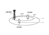
- FIGS. 6 to 8 are diagrams showing an operating environment according to the first embodiment. As shown in FIGS. 6 to 8, there are three options as the operating environment according to the first embodiment.
- the UE 100 # 1 is located in cell # 1.
- the UE 100 # 1 is in the RRC connected state or the RRC idle state in the cell # 1. Focusing on the UE 100 # 1, the cell # 1 is a serving cell (Camp on Cell), and the cell # 2 is an adjacent cell. Note that, when the UE 100 # 1 is in the RRC connected state, the cell # 1 is a serving cell.
- UE 100 # 2 is located in cell # 2.
- UE 100 # 2 is in the RRC connected state or the RRC idle state in cell # 2. Focusing on the UE 100 # 2, the cell # 1 is an adjacent cell, and the cell # 2 is a serving cell (Cam on Cell). Note that, when the UE 100 # 2 is in the RRC connected state, the cell # 2 is a serving cell.
- the eNB 200 # 1 forms a cell # 1 operated at the frequency f1 and a cell # 2 operated at the frequency f2.
- the eNB 200 # 1 forms the cell # 1 operated at the frequency f1
- the eNB 200 # 2 forms the cell # 2 operated at the frequency f2.
- the eNB 200 # 2 is a pico cell or a femto cell, and the coverage of the cell # 2 overlaps with the coverage of the cell # 1.
- the entire coverage of cell # 2 may overlap with the coverage of cell # 1, or a part of the coverage of cell # 2 may overlap with the coverage of cell # 1.
- eNB 200 # 1 forms cell # 1 operated at frequency f1
- eNB 200 # 2 forms cell # 2 operated at frequency f2.
- the eNB 200 # 2 is a macro cell, and the cell # 2 is provided around the cell # 1.
- a scenario is assumed in which an inter-cell discovery procedure for UE 100 # 1 to discover UE 100 # 2 is performed in such an operating environment.
- the UE 100 # 1 transmits a Discovery signal at the frequency f1 in the inter-cell discovery procedure, since the frequency of the cell # 2 in which the UE 100 # 2 is located is the frequency f2, the UE 100 # 2 The Discovery signal cannot be received.
- the UE 100 # 1 uses the radio resource having the frequency f2 different from the frequency f1, and uses the radio resource to discover the UE 100 # 2 located in the cell # 2 different from the cell # 1.
- the radio resource of the frequency f2 is a radio resource used exclusively for the uplink.
- UE100 # 1 transmits a Discovery signal using the synchronous information used by cell # 1.
- the UE 100 # 1 preferably transmits the Discovery signal at a timing synchronized with the eNB 200 # 1 forming the cell # 1.
- the UE 100 # 1 may transmit an allocation request for requesting allocation of radio resources of the frequency f2 to the eNB 200 # 1 that forms the cell # 1.
- the eNB 200 # 1 allocates a radio resource of the frequency f2 to the UE 100 # 1 as a radio resource (resource pool) that can be used for the D2D proximity service according to a signal received from the UE 100 # 1.
- the radio resource of frequency f2 is configured as a radio resource of the secondary cell of UE 100 # 1 when cell # 1 is the primary cell of UE 100 # 1.
- the secondary cell is operated at the frequency f2 and is a cell dedicated to the uplink, and is configured by the eNB 200 # 1 that forms the cell # 1.
- the eNB 200 # 1 forming the cell # 1 does not need to provide the uplink and the downlink at the frequency f2. That is, the secondary cell may be a cell used exclusively for the inter-cell discovery procedure.
- the first option is not limited to this, and the eNB 200 # 1 may form a cell operated at the frequency f2.
- the radio resource of the frequency f2 is scheduled by downlink control information (DCI; Downlink Control Information) dedicated to the D2D proximity service.
- DCI Downlink Control Information
- the downlink control information is transmitted from the eNB 200 # 1 that forms the cell # 1.
- the downlink control information is transmitted using the frequency f1.
- the eNB 200 # 1 forming the cell # 1 does not need to provide the uplink and the downlink at the frequency f2. That is, the secondary cell may be a cell used exclusively for the inter-cell discovery procedure.
- the second option is not limited to this, and the eNB 200 # 1 may form a cell operated at the frequency f2.
- FIG. 9 is a sequence diagram showing a first option according to the first embodiment.
- the operating environment shown in FIG. 6 is assumed.
- step S11 the UE 100 # 1 transmits an allocation request for requesting allocation of radio resources of the frequency f2 to the eNB 200 # 1 that forms the cell # 1.
- step S12 when the cell # 1 is the primary cell of the UE 100 # 1, the eNB 200 # 1 transmits a message (configuration message) for configuring the secondary cell of the UE 100 # 1 to the UE 100 # 1.
- a message configuration message
- the eNB 200 # 1 forming the cell # 1 does not need to provide the uplink and the downlink at the frequency f2.
- the eNB 200 # 1 allocates the radio resource of the frequency f2 to the eNB 200 # 1 as a radio resource dedicated to the D2D proximity service (a radio resource dedicated to the uplink).
- the radio resource of the frequency f2 is transmitted as a Discovery signal for discovering the UE 100 # 2 located in the cell # 2 (frequency f2) different from the cell # 1 (frequency f1) in the D2D proximity service. Used for.
- the UE 100 # 1 transmits a Discovery signal for discovering the UE 100 # 2 located in the cell # 2 different from the cell # 1, using the radio resource having the frequency f2 different from the frequency f1.
- the UE 100 # 1 preferably transmits the Discovery signal using the synchronization information used in the cell # 1.
- step S11 is not essential and eNB200 # 1 may transmit a Configuration message to UE100 # 1 based on another trigger.
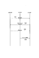
- FIG. 10 is a sequence diagram showing a second option according to the first embodiment.
- FIG. 10 it should be noted that the operating environment shown in FIG. 6 is assumed.
- step S21 the UE 100 # 1 transmits an allocation request for requesting allocation of radio resources of the frequency f2 to the eNB 200 # 1 forming the cell # 1.
- step S22 the eNB 200 # 1 transmits downlink control information (DCI; Downlink Control Information) dedicated to the D2D proximity service to the UE 100 # 1.
- the downlink control information is information for scheduling a radio resource with the frequency f2.
- the eNB 200 # 1 forming the cell # 1 does not need to provide the uplink and the downlink at the frequency f2.
- the eNB 200 # 1 allocates the radio resource of the frequency f2 to the eNB 200 # 1 as a radio resource dedicated to the D2D proximity service (a radio resource dedicated to the uplink).
- the radio resource of the frequency f2 is transmitted as a Discovery signal for discovering the UE 100 # 2 located in the cell # 2 (frequency f2) different from the cell # 1 (frequency f1) in the D2D proximity service. Used for.
- the UE 100 # 1 transmits a Discovery signal for discovering the UE 100 # 2 located in the cell # 2 different from the cell # 1, using the radio resource of the frequency f2 different from the frequency f1.
- the UE 100 # 1 preferably transmits the Discovery signal using the synchronization information used in the cell # 1.
- step S21 is not essential and eNB200 # 1 may transmit a Configuration message to UE100 # 1 based on another trigger.
- the UE 100 # 1 uses the radio resource of the frequency f2, A Discovery signal is transmitted.
- the UE 100 # 2 can receive the Discovery signal, and the inter-cell discovery procedure is appropriately performed. Can be done.
- the UE 100 # 1 transmits a Discovery signal using a radio resource having the frequency f2.
- the UE 100 # 1 transmits a Discovery signal using a radio resource having the frequency f2.
- the frequency of the cell in which a plurality of UEs 100 are located is aligned with the frequency at which the D2D proximity service is provided.
- the first modification is a scenario in which the D2D proximity service does not need to be provided in all the frequencies provided in the mobile communication system (WAN; Wide Area Network).
- the UE 100 does not need to support the D2D proximity service on all the frequencies provided by the mobile communication system (WAN).
- the frequency supporting the D2D proximity service may be different for each UE 100.
- the cell operated at the frequency f1 is a cell provided by the eNB 200 # 1.
- the cell operated at the frequency f1 may be a cell provided by the eNB 200 # 1 or a cell provided by the eNB 200 # 1.
- the cell operated at the frequency f1 is a cell provided by the eNB 200 # 2.
- step S31 the eNB 200 # 2 broadcasts information indicating a frequency at which the D2D proximity service is provided.
- information is notified by, for example, SIB (System Information Block).
- the UE 100 # 2 transmits a D2D interest notification (D2D Interest Indication) indicating that the UE 100 # 2 is interested in the D2D proximity service to the eNB 200 # 2.
- the UE 100 # 2 may transmit a D2D interest notification to the eNB 200 # 2 when the D2D proximity service is not provided at the frequency f2 with reference to the information received in Step S31.
- the UE 100 # 2 may transmit a D2D interest notification to the eNB 200 # 2 when the UE 100 # 2 is in a cell (frequency) where the D2D proximity service is not provided.
- the first modification is not limited to this, and the UE 100 # 2 may transmit the D2D interest notification to the eNB 200 # 2 without referring to the information received in step S31.
- the eNB 200 # 2 transmits a message (transition instruction) instructing the transition from the frequency f2 (cell # 2) to the frequency f1 (cell operated at the frequency f1) to the UE 100 # 2.
- the transition instruction is a handover instruction from the cell # 2 to the cell operated at the frequency f1.
- the transition instruction is sent from the cell # 2 to the cell operated at the frequency f1. It may be a cell change order (Cell Change Order).
- the eNB 200 # 2 transmits a cell change order (Cell Change Order) to the UE 100 # 2 together with an RRC connection release message (RRC Connection Release).
- step S33 the UE 100 # 2 performs a transition (handover or cell reselection) to the frequency f1 where the D2D proximity service is provided.
- step S34 the UE 100 # 2 scans the Discovery signal at the frequency f1. Thereby, UE100 # 2 can receive the Discovery signal transmitted from UE100 # 1.
- the D2D interest notification may include information indicating the type of D2D proximity service that the UE 100 # 1 is interested in.
- the type of D2D proximity service is, for example, information indicating whether or not inter-cell D2D communication is desired, information indicating the type of UE 100 that should perform inter-cell D2D communication, and the like.
- the eNB 200 is provided with the determination material for performing the transition (handover or cell reselection) of the UE 100 with respect to the frequency for which the D2D proximity service is provided.
- the frequency of the cell in which the plurality of UEs 100 are located is aligned with the frequency for which the D2D proximity service is provided (here, frequency f1) And the inter-cell discovery procedure can be performed appropriately.
- the UE 100 # 2 transmits the D2D interest notification. did.
- the eNB 200 # 1 forms a cell operated at the frequency f2 in addition to the cell # 1 operated at the frequency f1.
- the second modification is a scenario in which the D2D proximity service does not need to be provided in all the frequencies provided by the mobile communication system (WAN). Should. In other words, it should be noted that the UE 100 does not need to support the D2D proximity service on all the frequencies provided by the mobile communication system (WAN). The frequency supporting the D2D proximity service may be different for each UE 100.
- the UE 100 # 1 transmits a D2D interest notification to the eNB 200 # 1 that forms the cell # 1.
- the UE 100 # 1 may transmit a D2D interest notification to the eNB 200 # 1 when the UE 100 # 1 is in a cell (frequency) where the D2D proximity service is not provided.
- the eNB 200 # 1 that receives the D2D interest notification may transmit a message (transition instruction) instructing the transition from the frequency f1 to the frequency f2 to the UE 100 # 1, as described in Modification 3 described later.
- transition instruction instructing the transition from the frequency f1 to the frequency f2 to the UE 100 # 1, as described in Modification 3 described later.
- the UE 100 # 1 that receives the transition instruction preferably performs transition (handover or cell reselection) to the frequency f2 where the D2D proximity service is provided, as described in Modification 3 described later.
- the frequencies of the cells in which the plurality of UEs 100 are located are different from each other, the frequencies of the cells in which the plurality of UEs 100 are located are changed to the frequencies where the D2D proximity service is provided (
- the frequency f2) can be adjusted, and the inter-cell discovery procedure can be appropriately performed.
- information indicating the frequency at which the D2D proximity service is provided is broadcast from the eNB 200 # 1.
- Such information is notified by, for example, SIB (System Information Block).
- the frequency f2 radio resource allocation process (step S12 or step S22) is performed by the UE 100 # 1 to transmit an allocation request for requesting allocation of the radio resource of the frequency f2 to the eNB 200 # 1. Triggered by
- the radio resource allocation process (step S12 or step S22) of the frequency f2 is triggered by transmission of a D2D interest notification from the UE 100 # 1 to the eNB 200 # 1.
- step S11A the process of step S11A is performed instead of step S11 shown in FIG.
- step S11A the UE 100 # 1 transmits to the eNB 200 # 1 a D2D interest notification (D2D Interest Indication) indicating that it is interested in the D2D proximity service.
- step S21A the process of step S21A is performed instead of step S21 shown in FIG.
- step S21A the UE 100 # 1 transmits to the eNB 200 # 1 a D2D interest notification (D2D Interest Indication) indicating that the user is interested in the D2D proximity service.
- D2D Interest Indication D2D interest notification
- the radio resource dedicated to the uplink is a radio resource dedicated to the D2D proximity service.
- the radio resource dedicated to the uplink is a cell (for example, a pico cell or a femto cell) having a narrower coverage than that of a cell (for example, a macro cell) in which the UE 100 is located. It is used for transmission of a signal used to notify the managed eNB 200 of the presence of the UE 100.
- the eNB 200 # 11 forms a cell # 11 (for example, a macro cell) operated at the frequency f11.
- the eNB 200 # 12 forms a cell # 12 (for example, a pico cell or a femto cell) operated at the frequency f12.
- Cell # 12 has a narrower coverage than that of cell # 11.
- the coverage of cell # 12 overlaps with the coverage of cell # 11.
- UE 100 # 1 is located in cell # 11.
- the eNB 200 # 11 allocates a radio resource of the second frequency f12 different from the frequency f11 to the UE 100 # 1 located in the cell # 11.
- the radio resource of the second frequency f12 is used for transmission of a signal used to notify the eNB 200 # 12 that forms the cell # 12 of the presence of the UE 100 # 1.
- an example of such a signal is a RACH signal.
- the UE 100 # 1 can notify the eNB 200 # 12 that forms the cell # 12 of the presence of the UE 100 # 1 by transmitting the RACH signal using the radio resource of the second frequency f12.
- the UE 100 transmits a D2D interest notification (D2D Interest Indication) when the D2D function is turned on.
- the D2D function is a function for receiving a D2D proximity service.
- the D2D function is switched on / off by a user operation.
- the on / off of the D2D function may be switched depending on whether or not the UE 100 exists in a cell provided by a mobile communication system (WAN; Wide Area Network) instead of a user operation.
- WAN Wide Area Network
- the D2D proximity service may be provided by a plurality of frequencies.
- the eNB 200 may select a frequency that should provide the D2D proximity service from a plurality of frequencies in response to reception of the D2D interest notification.
- the eNB 200 may select a frequency that should provide the D2D proximity service according to the congestion status of each frequency and the interference status of each frequency.
- eNB200 may select the frequency which should provide D2D proximity service according to the combination of UE100 which receives D2D proximity service, when D2D proximity service is performed by unicast. As a result, it is possible to perform scheduling according to the combination of UEs 100 that receive the D2D proximity service.
- the D2D interest notification includes information indicating the frequency used for transmitting the Discovery signal, information indicating the frequency used for receiving the Discovery signal, or information indicating the frequency used for transmitting and receiving the Discovery signal. But you can.
- the frequency used for transmitting the Discovery signal and the frequency used for receiving the Discovery signal may be different from each other.
- a program for causing a computer to execute each process performed by the UE 100 and the eNB 200 may be provided.
- the program may be recorded on a computer readable medium. If a computer-readable medium is used, a program can be installed in the computer.
- the computer-readable medium on which the program is recorded may be a non-transitory recording medium.
- the non-transitory recording medium is not particularly limited, but may be a recording medium such as a CD-ROM or a DVD-ROM.
- a chip configured by a memory that stores a program for executing each process performed by the UE 100 and the eNB 200 and a processor that executes the program stored in the memory may be provided.
- the LTE system has been described as an example of a mobile communication system.
- the mobile communication system may be a system other than the LTE system.
- FIGS. 6-8 Possible deployment scenarios for inter-frequency discovery are shown in FIGS. 6-8, where UE1 is located / connected to cell 1 operating on f1, and UE2 is located / connected to cell 2 operating on f2. ing.
- the eNB that operates the cell 1 or the cell 2 may or may not operate the SCell on f2 or f1.
- Scenarios can be classified into three cases depending on whether intra-eNB / homogeneous network (HomoNet), inter-eNB / heterogeneous network (HetNet), and inter-eNB / HomoNet are deployed. These cases are illustrated in FIGS. 6-8, respectively. The actual deployment may consist of a combination of these classified cases.
- HomoNet homogeneous network
- HetNet inter-eNB / heterogeneous network
- HomoNet inter-eNB / HomoNet
- intra-eNB carrier aggregation may be included, that is, each UE is capable of CA, but a different frequency is set for each PCell. That is, the PCell of UE1 is cell 1 on f1, and the PCell of UE2 is cell 2 on f2.
- the SCell for UE1 is set in cell 2 and eNB1 permits D2D operation on cell 2. In this case, UE1 and UE2 can execute D2D via f2 without much problem.
- the D2D operation is a little more complicated. This is because the RRC connection of the UE is established across different eNBs. Assuming that UE2 is a dual connection (DC) capable UE, f1 is set for RRC connection and f2 is set for secondary resources, UE1 is served only on f1, UE2 will be able to execute D2D with UE1 on f1.
- DC dual connection
- both UEs may be provided with a common coverage cell on a certain frequency.
- one simple way to support inter-frequency discovery is to ensure that all D2D UEs are served under the same frequency and under the same overlapping cell.
- D2D operation involves the most complex network plan, but this does not have an overlapping layer of both D2D UEs and is standardized via X2 This is because such collaboration is not allowed in Rel-12.
- Proposal 1 It should be assumed that at least in Rel-12, UEs attempting inter-frequency discovery are equipped with at least one overlapping cell operating on one frequency.
- Plan 1 assumes that all operating frequencies allow D2D operation, which may or may not include D2D Discovery or D2D communication.
- Plan 2 it is assumed that two of the three operating frequencies allow D2D operation. The above two plans require several mechanisms for inter-frequency discovery.
- inter-frequency discovery The main purpose of inter-frequency discovery is to allow the UE to be served under the D2D allowed frequency, and the frequency where the UE is currently being served is not one of the D2D allowed frequencies. It is assumed that there is. In order to make it easier for the UE to tune to an appropriate frequency for D2D Discovery monitoring / transmission, it should allow non-D2D serving cells to provide a list of surrounding frequencies that support D2D. This is the same as the scenario for MBMS in which both the MBMS cell and the non-MBMS cell notify the MBMS SAI of the current frequency and each peripheral frequency in the SIB 15.
- Proposal 2 The D2D grant frequency should be provided by the serving cell's SIB, whether or not the serving cell allows D2D operation.
- inter-frequency discovery may be achieved by one or more of the following three options.
- Option 1 UE1 transmits a Discovery signal on f1, and then UE2 receives the signal on f1. That is, it is an inter-frequency Discovery cell reception mechanism.
- UE2 has at least both frequency receivers.
- the UE has dual receiver and / or carrier aggregation capabilities.
- UE1 transmits a Discovery signal on f2, for example, with an inter-frequency Discovery transmission mechanism, and then UE2 receives the signal on f2.
- UE1 has transmitters for at least both frequencies.
- the UE has dual transmitter and / or carrier aggregation capabilities.
- Option 3 UE1 transmits a Discovery signal on f1, and then UE2 receives the signal on f1 after handover to f1.
- the eNB operating the cell 2 has another cell operable on f1.
- Option 1 is a simple scheme. This is because the cell 1 allocates only resources within its operating frequency to the UE 1 for transmitting the Discovery signal, while the UE 2 needs to receive the Discovery signal on a frequency different from the serving frequency.
- Option 2 has the potential for more flexibility in network planning, assuming multi-carrier D2D operation is supported, such as plan 1 in Table 1, for example.
- This option is expected to benefit D2D communications, especially in the case of unicast, but only creates unnecessary complexity for Rel-12. This is because Discovery and one-to-many D2D communication are assumed for broadcast transmission / reception, that is, a transmission signal needs to be received by all D2D-capable UEs in the area.
- Option 3 is actually a mechanism for trying and reusing in-frequency D2D Discovery as much as possible under a multi-frequency deployment scenario. Since the existing in-frequency D2D Discovery mechanism is reused, Option 3 has the least impact on the UE. This is because D2D discovery is performed only on the D2D operation, that is, on a common frequency that permits plan 3 in Table 1.
- Proposal 3 In RAN2, schemes for Discovery signals transmitted on a frequency different from the serving frequency for Rel-12 should be excluded.
- ENB may provide D2D reception Discovery resources in SIB. These resources may cover resources used for D2D transmission in this cell and resources used in neighboring cells. (Details will be examined in the future (FFS))
- RAN1 agreed on the following aspects.
- the eNB may provide the SIB with (multiple) radio resource pools for D2D UEs for discovery reception for Type-2B. Future consideration (FFS) on whether it is a common reception pool (s) for Type 1 and Type-2B Discovery or different reception pools. The UE does not need to decode neighboring cell SIBs.
- FFS Future consideration
- a resource hopping mechanism can be applied after resource allocation by the eNB. Details of the resource hopping mechanism will be examined in the future.
- the UE can receive a signal without decoding any SIB transmitted from the neighboring cell.
- neighboring cell typically includes neighboring cells on the same frequency as well as different frequencies.
- an inter-frequency Discovery scenario is not clearly studied. Therefore, details need to be reviewed and defined.
- the SIB transmitted by the serving cell should include D2D Discovery resources on the serving frequency and surrounding frequencies. If there are available Discovery resources provided via SIB, the D2D UE will be able to receive D2D Discovery signals from UEs on neighboring inter-frequency cells. Our assumption is that to support inter-frequency discovery using option 1, some extension parameters can be attached to the IE, defined for inter-cell discovery, and the existing inter-frequency measurement mechanism can be reused. That's what it means.
- Proposal 4 As a baseline, if Option 1 is supported in Rel-12, RAN2 should consider reusing the existing inter-frequency measurement mechanism for inter-frequency discovery.
- RAN1 assumed 16-64 subframes per Discovery period for performance evaluation in the research phase. In the inter-frequency measurement, the existing measurement gap length is fixed to 6 subframes. Without further improvement, Discovery detectability, i.e. the chance of discovering D2D UEs, will be reduced to at least 1/3.
- the relationship between the measurement value related to the RRM of the eNB (that is, RSRP / RSRQ) and the discovery signal reception power from other D2D UEs may not be directly related.
- the D2D UE may receive the Discovery signal from the D2D UE in the adjacent cell even if the D2D UE does not approach the adjacent cell.
- the decision to allocate the discovery gap should be left to the eNB implementation, but there is no reason to reject the D2D UE from the continuous monitoring of the D2D Discovery. If the D2D UE is not interested in transmission / reception of the D2D Discovery, the D2D UE should notify the serving eNB of the state of the D2D operation, that is, whether the D2D operation has been disabled by the user.
- Discovery monitoring gap is defined using a larger number of subframes than the existing measurement gap length.
- Proposal 5 If Option 1 is supported, RAN2 should consider the trade-off between Discovery detectability and WAN UL / DL transmission opportunities.
- inter-frequency measurement and inter-frequency The simultaneous operation with Discovery should be considered.
- Inter-frequency measurements require a DL receiver and do not require a UL transceiver. That is, the D2D receiver is free during the gap. Therefore, the UE can receive the Discovery signal during the same gap.
- the inter-frequency monitoring of the Discovery signal may be performed during the existing measurement gap or may be performed simultaneously with the inter-frequency measurement.
- Proposal 6 If Option 1 is selected as the baseline, RAN2 should assume that inter-frequency monitoring of Discovery signals is performed with existing inter-frequency measurements using the same measurement gap.
- the frequency means a carrier including within and between bands.
- CA-capable UEs may be considered for inter-frequency discovery.
- the CA capable UE can simultaneously transmit / monitor the Discovery signal on the PCell and the SCell. Therefore, as long as the D2D Discovery frequency belongs to one of the UE's serving cell (ie, PCell or SCell) frequency, the “Discovery monitoring gap” is not necessary for such UE.
- Option 3 is mainly applicable to plan 2 or 3 in Table 1. That is, it is not applicable to all cellular frequency support D2D. This option assumes that the handover has been completed before Discovery is initiated. In particular, if a D2D-capable UE is served on a frequency that does not support D2D operation, the eNB should hand over the UE to a target cell operating on the D2D allowed frequency.
- the SIB provided on a frequency that does not allow D2D operation does not include any D2D related information, eg, Discovery reception resources
- a UE being served / serviced on the above frequency may send a Discovery signal on a different frequency. There is no way to send and receive. This is a scenario that could be in the case of a stand-alone small cell deployment, for example the case of FIG. This is because there is currently no agreement on whether non-D2D operating cells should provide D2D related information in their SIBs.
- the D2D Discovery resource is provided in the SIB for a cell that does not support D2D
- the cell does not support any D2D operation, so that the cell uses the Type-2B Discovery resource as a UE. Cannot be assigned.
- option 3 should be combined with option 1 or option 2.
- D2D capable UEs are served on the same cell, eg, Plan 3 in Table 1, the cell may be involved in traffic jams, for example, the load of WAN communication caused by multiple frequency deployments There may be fewer opportunities to balance. To avoid this problem, only D2D-capable UEs that are part of D2D-capable UEs should be considered handed over to D2D-allowed cells, and if the UE cannot perform D2D, D2D-disabled UEs Is determined based on whether it remains in the cell or is handed over to another cell, the current load in the cell, etc., depending on the implementation of the eNB.
- the eNB may hand over the UE to the Discovery allowed cell.
- the Discovery mechanism can be enabled / disabled by the user as follows.
- the eNB should have the ability to know whether or not the UE enables its Discovery function.
- This use case is similar to the existing MBMS interest notification concept. Therefore, we assume that we introduce a solution like MBMS that causes inter-frequency handover, namely “D2D interest notification”.
- Proposal 7 If the UE enables / disables its Discovery functionality, the UE should have the ability to notify the eNB.
- the IDLE UE In order to obtain the same efficiency as when the UE sends and receives D2D Discovery signals, the IDLE UE should be allowed to prioritize the D2D frequency as part of the reselection procedure.
- the frequency priority for reselection is determined by the eNB, but if the IDLE UE is interested in D2D, it should allow the IDLE UE to prioritize the D2D frequency. This idea is similar to the current MBMS behavior where IDLE UEs interested in MBMS are given permission to prioritize MBMS frequencies for reselection.
- Proposal 8 IDLE UE capable of D2D should be allowed to prioritize D2D frequency for reselection.
- the IDLE UE may prioritize the D2D frequency based on the D2D information provided in the SIB of its serving cell.
- Proposal 9 In RAN2, one or more of the above (multiple) options should be adopted in Rel-12, and it should be examined whether to support inter-frequency discovery.
- the present invention is useful in the communication field.
Landscapes
- Engineering & Computer Science (AREA)
- Computer Networks & Wireless Communication (AREA)
- Signal Processing (AREA)
- Computer Security & Cryptography (AREA)
- Databases & Information Systems (AREA)
- Mobile Radio Communication Systems (AREA)
Abstract
Description
実施形態に係るユーザ端末は、D2D近傍サービスをサポートする移動通信システムにおいて、第1周波数で運用されている第1セルに在圏する。ユーザ端末は、前記第1周波数とは異なる第2周波数の無線リソースを用いて、前記第1セルとは異なる第2セルに在圏する近傍端末発見のためのDiscovery信号を送信する送信部を備える。前記第2周波数の無線リソースは、上りリンクに専用で用いられる無線リソースである。
以下において、移動通信システムとして、3GPP規格に基づいたLTEシステムを例に挙げて、第1実施形態を説明する。
先ず、第1実施形態に係るLTEシステムのシステム構成について説明する。図1は、第1実施形態に係るLTEシステムの構成図である。
以下において、D2D近傍サービスについて説明する。第1実施形態に係るLTEシステムは、D2D近傍サービスをサポートする。
以下において、第1実施形態に係る動作環境について説明する。図6~図8は、第1実施形態に係る動作環境を示す図である。図6~図8に示すように、第1実施形態に係る動作環境としては、3つのオプションが存在する。
以下において、第1実施形態に係る動作について説明する。以下において、上述した第1オプション及び第2オプションについて説明する。
図9は、第1実施形態に係る第1オプションを示すシーケンス図である。図9において、図6に示す動作環境が前提となっていることに留意すべきである。
図10は、第1実施形態に係る第2オプションを示すシーケンス図である。図10において、図6に示す動作環境が前提となっていることに留意すべきである。
第1実施形態では、「上りリンクに専用で用いられる第2周波数の無線リソース」という新たな概念を導入するとともに、UE100#1は、周波数f2の無線リソースを用いて、Discovery信号を送信する。これによって、第1セルで運用されている周波数と第2セルで運用されている周波数とが異なるケースであっても、UE100#2がDiscovery信号を受信することができ、セル間発見手順を適切に行うことができる。
以下において、第1実施形態の変更例1について説明する。以下においては、第1実施形態に対する相違点について主として説明する。
変更例1では、「D2D近傍サービスに興味がある旨を示すD2D興味通知」という新たな概念を導入するとともに、UE100#2は、セル#2を形成するeNB200#2に対して、D2D興味通知を送信する。言い換えると、D2D近傍サービスが提供されている周波数に対するUE100の遷移(ハンドオーバ又はセルリセレクション)を行うための判断材料がeNB200に提供される。従って、複数のUE100が在圏するセルの周波数が互いに異なる場合であっても、複数のUE100が在圏するセルの周波数をD2D近傍サービスが提供されている周波数(ここでは、周波数f1)に揃えることができ、セル間発見手順を適切に行うことができる。
以下において、第1実施形態の変更例2について説明する。以下においては、変更例1に対する相違点について主として説明する。
以下において、第1実施形態の変更例3について説明する。以下においては、第1実施形態及び変更例2に対する相違点について主として説明する。
以下において、第1実施形態の変更例4について説明する。以下においては、第1実施形態に対する相違点について主として説明する。
本発明は上述した実施形態によって説明したが、この開示の一部をなす論述及び図面は、この発明を限定するものであると理解すべきではない。この開示から当業者には様々な代替実施形態、実施例及び運用技術が明らかとなろう。
以下において、実施形態の補足事項について付記する。
本付記では、周波数間Discoveryについて検討する。
周波数間Discoveryの可能な配備シナリオは、図6~図8に示され、UE1がf1上で動作するセル1に在圏/接続し、UE2がf2上で動作するセル2に在圏/接続している。セル1又はセル2を動作させるeNBは、f2又はf1上においてSCellを動作させてもよく、動作させなくてもよい。

可能な配備シナリオを考慮に入れて、周波数間Discoveryは、以下の3つの選択肢のうちの1つ以上により達成されてもよい。
(4.1. 選択肢1の詳細)
(4.1.1. 周波数間Discovery信号の受信)
周波数内Discoveryに関する、セル内及びセル間のシナリオの両方がRAN2で検討されており、研究事項フェーズ中にいくつかの合意が得られた。幾つかの検討がまた、作業項目フェーズ下で開始されている。セル間Discoveryに関しては、RAN2では、D2D受信Discoveryリソースに関して以下の合意が得られた。
(4.1.2.1. 測定ギャップ長及びトリガ)
TRの表10.1-2によれば、RAN1は、研究フェーズにおける性能評価のためのDiscovery期間毎に16~64個のサブフレームを想定した。周波数間測定において、既存の測定ギャップ長が、6個のサブフレームに固定されている。これ以上向上しなければ、Discoveryの検出可能性、つまり、D2D UEを発見する機会が少なくとも1/3に下がってしまうであろう。
これまで我々は、表1のプランに示されるように、WAN通信用のサポート周波数の数に拘らず、単一のD2D送受信機を有するUEだけが任意の所与の時間に1つの周波数上で動作する能力を有すると想定してきた。
(4.2.1. D2D Discoveryのハンドオーバ手順)
選択肢3は、主に、表1のプラン2又は3に適用可能である。つまり、セルラ周波数サポートD2D全てに適用可能ではない。この選択肢は、ハンドオーバはDiscoveryが開始される前に完了していると想定している。特に、D2D実施可能UEが、D2D動作をサポートしていない周波数上でサービスを提供されている場合、eNBは、D2D許可周波数上で動作する対象セルにUEをハンドオーバさせるべきである。
(4.2.2.1. Discoveryのためのハンドオーバのトリガ)
全てのD2D可能UEが、同じセル上、例えば、表1のプラン3でサービスを提供されている場合、セルは、渋滞に巻き込まれたり、例えば、複数の周波数の配備によってもたらされるWAN通信の負荷をバランス化する機会が少なくなったりする場合がある。この問題を避けるため、D2D可能UEの一部であるD2D実施可能UEだけが、D2D許可セルへハンドオーバされると考えられるべきであり、UEが、D2Dを実施することができない場合、D2D不能UEが、セルに留まるか、又は他のセルへハンドオーバされるか、セル内の現在の負荷等に基づいて決定され、これは、eNBの実装次第である。
セクション4.2.2.1で提案した方法は、RRC接続中のUEにとって有用であるが、アイドル状態のUEにとって有用ではない。IDLE UEは、D2D Discoveryが可能になる前に、CONNECTEDに遷移し、D2D興味通知を送信し、D2D可能セルにハンドオーバする必要があるだろう。
まとめとして、表2に示す通り、選択肢(Alternative)の比較を提示する。

米国仮出願第61/990936号(2014年5月9日出願)の全内容が参照により本願明細書に組み込まれている。
Claims (16)
- D2D近傍サービスをサポートする移動通信システムにおいて、第1周波数で運用されている第1セルに在圏するユーザ端末であって、
前記第1周波数とは異なる第2周波数の無線リソースを用いて、前記第1セルとは異なる第2セルに在圏する近傍端末発見のためのDiscovery信号を送信する送信部を備え、
前記第2周波数の無線リソースは、上りリンクに専用で用いられる無線リソースであることを特徴とするユーザ端末。 - 前記第2周波数の無線リソースは、前記第1セルを前記ユーザ端末のプライマリセルとした場合に、前記ユーザ端末のセカンダリセルの無線リソースとして構成され、
前記セカンダリセルは、前記第2周波数で運用され、かつ、上りリンクに専用のセルであり、前記第1セルを形成する基地局によって構成されることを特徴とする請求項1に記載のユーザ端末。 - 前記第2周波数の無線リソースは、前記D2D近傍サービスに専用の下りリンク制御情報によってスケジューリングされ、
前記下りリンク制御情報は、前記第1セルを形成する基地局から送信されることを特徴とする請求項1に記載のユーザ端末。 - 前記送信部は、前記第1セルで用いる同期情報を用いて、前記Discovery信号を送信することを特徴とする請求項1に記載のユーザ端末。
- 前記送信部は、前記第1セルを形成する基地局に対して、前記第2周波数の無線リソースの割り当てを要求する割当要求を送信することを特徴とする請求項1に記載のユーザ端末。
- 少なくとも第1周波数で運用されている第1セルを形成する基地局であって、
前記第1セルに在圏するユーザ端末に対して、前記第1周波数とは異なる第2周波数の無線リソースを割り当てる制御部を備え、
前記第2周波数の無線リソースは、上りリンクに専用で用いられる無線リソースであることを特徴とする基地局。 - 前記第2周波数の無線リソースは、D2D近傍サービスにおいて前記第1セルとは異なる第2セルに在圏する近傍端末を発見するためのDiscovery信号の送信に用いられることを特徴とする請求項6に記載の基地局。
- 前記第2周波数は、前記第1セルのカバレッジよりも狭いカバレッジを有する第2セルで用いられる周波数であり、
前記第2周波数の無線リソースは、前記第2セルを管理する基地局に対して、前記ユーザ端末の存在を知らせるために用いる信号の送信に用いられることを特徴とする請求項6に記載の基地局。 - D2D近傍サービスをサポートする移動通信システムにおいて、第1周波数で運用されている第1セルに在圏するユーザ端末であって、
前記第1セルを形成する基地局に対して、前記D2D近傍サービスに興味がある旨を示すD2D興味通知を送信する送信部を備えることを特徴とするユーザ端末。 - 前記送信部は、前記第1周波数で前記D2D近傍サービスが提供されておらず、前記第1周波数とは異なる第2周波数で前記D2D近傍サービスが提供されている場合に、前記D2D興味通知を送信することを特徴とする請求項9に記載のユーザ端末。
- 前記D2D近傍サービスが提供される周波数を示す情報は、前記第1セルを形成する基地局から報知されることを特徴とする請求項10に記載のユーザ端末。
- 前記D2D興味通知は、前記ユーザ端末が興味を有する前記D2D近傍サービスの種類を示す情報を含むことを特徴とする請求項9に記載のユーザ端末。
- 前記第1周波数とは異なる第2周波数で前記D2D近傍サービスが提供されている場合に、前記第1周波数から前記第2周波数への遷移を指示するメッセージを前記基地局から受信する受信部を備えることを特徴とする請求項9に記載のユーザ端末。
- 前記ユーザ端末が自身のDiscoveryの機能性を有効化又は無効化する場合、前記送信部は、前記基地局に前記D2D興味通知を送信することを特徴とする請求項9に記載のユーザ端末。
- D2D近傍サービスをサポートする移動通信システムにおいて、第1周波数で運用されている第1セルに在圏するユーザ端末であって、
サービング周波数である前記第1周波数で受信を行うための第1の受信機と、
前記第1周波数とは異なる第2周波数で受信を行うための第2の受信機と、
前記第2周波数で他のユーザ端末から送信されるDiscovery信号を前記第2の受信機により監視する制御部と、
を備えることを特徴とするユーザ端末。 - D2D近傍サービスをサポートする移動通信システムにおいて、第1周波数で運用されている第1セルに在圏するユーザ端末であって、
サービング周波数である前記第1周波数で送信を行うための第1の送信機と、
前記第1周波数とは異なる第2周波数で送信を行うための第2の送信機と、
前記第2周波数で前記第2の送信機により他のユーザ端末に対してDiscovery信号を送信する処理を行う制御部と、
を備えることを特徴とするユーザ端末。
Priority Applications (4)
| Application Number | Priority Date | Filing Date | Title |
|---|---|---|---|
| EP15789282.9A EP3142421B1 (en) | 2014-05-09 | 2015-05-08 | Device to device proximity service for terminals served by different cells |
| JP2016517932A JP6211179B2 (ja) | 2014-05-09 | 2015-05-08 | ユーザ端末及びプロセッサ |
| US15/048,056 US9521641B2 (en) | 2014-05-09 | 2016-02-19 | User terminal and base station for a device to device proximity service |
| US15/354,290 US9942743B2 (en) | 2014-05-09 | 2016-11-17 | User terminal and base station for a device to device proximity service |
Applications Claiming Priority (2)
| Application Number | Priority Date | Filing Date | Title |
|---|---|---|---|
| US201461990936P | 2014-05-09 | 2014-05-09 | |
| US61/990,936 | 2014-05-09 |
Related Child Applications (1)
| Application Number | Title | Priority Date | Filing Date |
|---|---|---|---|
| US15/048,056 Continuation US9521641B2 (en) | 2014-05-09 | 2016-02-19 | User terminal and base station for a device to device proximity service |
Publications (1)
| Publication Number | Publication Date |
|---|---|
| WO2015170729A1 true WO2015170729A1 (ja) | 2015-11-12 |
Family
ID=54392578
Family Applications (1)
| Application Number | Title | Priority Date | Filing Date |
|---|---|---|---|
| PCT/JP2015/063261 WO2015170729A1 (ja) | 2014-05-09 | 2015-05-08 | ユーザ端末及び基地局 |
Country Status (4)
| Country | Link |
|---|---|
| US (2) | US9521641B2 (ja) |
| EP (1) | EP3142421B1 (ja) |
| JP (1) | JP6211179B2 (ja) |
| WO (1) | WO2015170729A1 (ja) |
Cited By (1)
| Publication number | Priority date | Publication date | Assignee | Title |
|---|---|---|---|---|
| JP2020523887A (ja) * | 2017-06-15 | 2020-08-06 | ブラックベリー リミテッドBlackBerry Limited | サイドリンク通信の構成 |
Families Citing this family (8)
| Publication number | Priority date | Publication date | Assignee | Title |
|---|---|---|---|---|
| US10588007B2 (en) * | 2014-08-08 | 2020-03-10 | Lg Electronics Inc. | Device-to-device (D2D) operation method performed by terminal in wireless communications system and terminal using same |
| US10531503B2 (en) * | 2014-10-14 | 2020-01-07 | Lg Electronics Inc. | Device-to-device (D2D) operation method of user equipment in wireless communication system and user equipment using the method |
| WO2016122192A1 (en) * | 2015-01-26 | 2016-08-04 | Lg Electronics Inc. | Method and apparatus for performing d2d operation in wireless communication system |
| KR102116360B1 (ko) * | 2015-04-10 | 2020-05-28 | 후아웨이 테크놀러지 컴퍼니 리미티드 | 데이터 송신 방법 및 장치 |
| WO2017048011A1 (ko) * | 2015-09-18 | 2017-03-23 | 엘지전자 주식회사 | 상향링크 신호와 prose 신호를 전송하는 방법 및 사용자 장치 |
| WO2017197393A1 (en) * | 2016-05-13 | 2017-11-16 | Intel Corporation | User equipment (ue) and evolved node b to reselect resources in a vehicle to vehicle (v2v) communication system according to channel congestion |
| US11096016B2 (en) | 2017-01-12 | 2021-08-17 | Asustek Computer Inc. | Method and apparatus of handling interest indication in a wireless communication system |
| EP4014686A4 (en) * | 2019-08-14 | 2023-08-09 | Telefonaktiebolaget Lm Ericsson (Publ) | NETWORK NODE, END DEVICE, AND RRC STATE TRANSITION CONTROL METHODS |
Citations (3)
| Publication number | Priority date | Publication date | Assignee | Title |
|---|---|---|---|---|
| WO2013171115A1 (en) * | 2012-05-15 | 2013-11-21 | Telefonaktiebolaget L M Ericsson (Publ) | Beacon management for network assisted device-to-device (d2d) communication |
| WO2014034572A1 (ja) * | 2012-08-28 | 2014-03-06 | 京セラ株式会社 | 移動通信システム、ユーザ端末、プロセッサ及び記憶媒体 |
| WO2015053382A1 (ja) * | 2013-10-11 | 2015-04-16 | 京セラ株式会社 | 通信制御方法、ユーザ端末及び通信装置 |
Family Cites Families (7)
| Publication number | Priority date | Publication date | Assignee | Title |
|---|---|---|---|---|
| US20070054664A1 (en) * | 2005-09-01 | 2007-03-08 | Pantech & Curitel Communications, Inc. | Wireless communication terminal and method for emergency call connection using hand-off |
| US9516686B2 (en) * | 2010-03-17 | 2016-12-06 | Qualcomm Incorporated | Method and apparatus for establishing and maintaining peer-to-peer (P2P) communication on unlicensed spectrum |
| EP2850857B1 (en) * | 2012-05-15 | 2019-03-06 | Telefonaktiebolaget LM Ericsson (publ) | Device discovery of second user equipments in a second network for d2d communication |
| WO2014003342A1 (ko) * | 2012-06-26 | 2014-01-03 | 엘지전자 주식회사 | 무선 통신 시스템에서 d2d(device-to-device) 통신을 위한 신호 송수신 방법 및 장치 |
| EP2892258A4 (en) * | 2012-08-29 | 2016-04-20 | Kyocera Corp | MOBILE COMMUNICATION SYSTEM, BASE STATION, USER TERMINAL AND PROCESSOR |
| EP2914056B1 (en) * | 2012-10-29 | 2018-05-23 | KYOCERA Corporation | Apparatuses and method for device-to-device (d2d) communications in a mobile communication system |
| CN105191178B (zh) * | 2013-05-01 | 2019-06-28 | 三星电子株式会社 | 用于设备到设备通信系统的方法和装置 |
-
2015
- 2015-05-08 WO PCT/JP2015/063261 patent/WO2015170729A1/ja active Application Filing
- 2015-05-08 JP JP2016517932A patent/JP6211179B2/ja active Active
- 2015-05-08 EP EP15789282.9A patent/EP3142421B1/en active Active
-
2016
- 2016-02-19 US US15/048,056 patent/US9521641B2/en active Active
- 2016-11-17 US US15/354,290 patent/US9942743B2/en active Active
Patent Citations (3)
| Publication number | Priority date | Publication date | Assignee | Title |
|---|---|---|---|---|
| WO2013171115A1 (en) * | 2012-05-15 | 2013-11-21 | Telefonaktiebolaget L M Ericsson (Publ) | Beacon management for network assisted device-to-device (d2d) communication |
| WO2014034572A1 (ja) * | 2012-08-28 | 2014-03-06 | 京セラ株式会社 | 移動通信システム、ユーザ端末、プロセッサ及び記憶媒体 |
| WO2015053382A1 (ja) * | 2013-10-11 | 2015-04-16 | 京セラ株式会社 | 通信制御方法、ユーザ端末及び通信装置 |
Non-Patent Citations (6)
| Title |
|---|
| HUAWEI ET AL.: "Comparison of Type 1, Type 2a, and Type 2b Discovery Resource Allocation", 3GPP TSG-RAN WG2#83BIS R2-133278, 7 October 2013 (2013-10-07), XP050718969 * |
| INTEL CORPORATION: "Type 1 Resource Allocation for D2D discovery", 3GPP TSG-RAN WG2#84 R2-134285, 11 November 2013 (2013-11-11), XP050737023 * |
| KYOCERA: "Consideration of Inter- cell D2D Service", 3GPP TSG-RAN WG2#85BIS R2-141386, 31 March 2014 (2014-03-31), XP050792578 * |
| KYOCERA: "Inter-frequency discovery considerations", 3GPP TSG-RAN WG2#86 R2-142240, 19 May 2014 (2014-05-19), XP050790161 * |
| QUALCOMM INCORPORATED: "Techniques for D2D Discovery", 3GPP TSG-RAN WG1 #73 R1-132503, 20 May 2013 (2013-05-20), XP050698221 * |
| See also references of EP3142421A4 * |
Cited By (3)
| Publication number | Priority date | Publication date | Assignee | Title |
|---|---|---|---|---|
| JP2020523887A (ja) * | 2017-06-15 | 2020-08-06 | ブラックベリー リミテッドBlackBerry Limited | サイドリンク通信の構成 |
| JP7094994B2 (ja) | 2017-06-15 | 2022-07-04 | ブラックベリー リミテッド | サイドリンク通信の構成 |
| US11632816B2 (en) | 2017-06-15 | 2023-04-18 | Blackberry Limited | Configuring sidelink communications |
Also Published As
| Publication number | Publication date |
|---|---|
| EP3142421A4 (en) | 2018-01-17 |
| US20160174181A1 (en) | 2016-06-16 |
| US9942743B2 (en) | 2018-04-10 |
| US20170070876A1 (en) | 2017-03-09 |
| EP3142421A1 (en) | 2017-03-15 |
| JP6211179B2 (ja) | 2017-10-11 |
| EP3142421B1 (en) | 2019-07-03 |
| JPWO2015170729A1 (ja) | 2017-04-20 |
| US9521641B2 (en) | 2016-12-13 |
Similar Documents
| Publication | Publication Date | Title |
|---|---|---|
| JP6475885B2 (ja) | 無線基地局、ユーザ端末及びプロセッサ | |
| JP6441264B2 (ja) | 通信制御方法、ユーザ端末、基地局、及びプロセッサ | |
| JP6211179B2 (ja) | ユーザ端末及びプロセッサ | |
| JP6224861B2 (ja) | ユーザ端末、プロセッサ、及び方法 | |
| JP6140180B2 (ja) | 移動通信システム、ユーザ端末、基地局、プロセッサ及び通信制御方法 | |
| WO2016021700A1 (ja) | 通信制御方法及びユーザ端末 | |
| WO2015125717A1 (ja) | 移動体通信システム、特定基地局、及びユーザ端末 |
Legal Events
| Date | Code | Title | Description |
|---|---|---|---|
| 121 | Ep: the epo has been informed by wipo that ep was designated in this application |
Ref document number: 15789282 Country of ref document: EP Kind code of ref document: A1 |
|
| ENP | Entry into the national phase |
Ref document number: 2016517932 Country of ref document: JP Kind code of ref document: A |
|
| REEP | Request for entry into the european phase |
Ref document number: 2015789282 Country of ref document: EP |
|
| WWE | Wipo information: entry into national phase |
Ref document number: 2015789282 Country of ref document: EP |
|
| NENP | Non-entry into the national phase |
Ref country code: DE |