WO2015170435A1 - Terminal, station de base, procédé de transmission et procédé de réception - Google Patents
Terminal, station de base, procédé de transmission et procédé de réception Download PDFInfo
- Publication number
- WO2015170435A1 WO2015170435A1 PCT/JP2015/001292 JP2015001292W WO2015170435A1 WO 2015170435 A1 WO2015170435 A1 WO 2015170435A1 JP 2015001292 W JP2015001292 W JP 2015001292W WO 2015170435 A1 WO2015170435 A1 WO 2015170435A1
- Authority
- WO
- WIPO (PCT)
- Prior art keywords
- signal
- terminal
- sequence
- subframe
- orthogonal code
- Prior art date
Links
Images


Classifications
-
- H—ELECTRICITY
- H04—ELECTRIC COMMUNICATION TECHNIQUE
- H04W—WIRELESS COMMUNICATION NETWORKS
- H04W72/00—Local resource management
- H04W72/20—Control channels or signalling for resource management
- H04W72/23—Control channels or signalling for resource management in the downlink direction of a wireless link, i.e. towards a terminal
-
- H—ELECTRICITY
- H04—ELECTRIC COMMUNICATION TECHNIQUE
- H04B—TRANSMISSION
- H04B1/00—Details of transmission systems, not covered by a single one of groups H04B3/00 - H04B13/00; Details of transmission systems not characterised by the medium used for transmission
- H04B1/69—Spread spectrum techniques
- H04B1/707—Spread spectrum techniques using direct sequence modulation
-
- H—ELECTRICITY
- H04—ELECTRIC COMMUNICATION TECHNIQUE
- H04J—MULTIPLEX COMMUNICATION
- H04J11/00—Orthogonal multiplex systems, e.g. using WALSH codes
-
- H—ELECTRICITY
- H04—ELECTRIC COMMUNICATION TECHNIQUE
- H04J—MULTIPLEX COMMUNICATION
- H04J13/00—Code division multiplex systems
- H04J13/0007—Code type
- H04J13/004—Orthogonal
-
- H—ELECTRICITY
- H04—ELECTRIC COMMUNICATION TECHNIQUE
- H04J—MULTIPLEX COMMUNICATION
- H04J13/00—Code division multiplex systems
- H04J13/0074—Code shifting or hopping
-
- H—ELECTRICITY
- H04—ELECTRIC COMMUNICATION TECHNIQUE
- H04J—MULTIPLEX COMMUNICATION
- H04J13/00—Code division multiplex systems
- H04J13/16—Code allocation
- H04J13/18—Allocation of orthogonal codes
-
- H—ELECTRICITY
- H04—ELECTRIC COMMUNICATION TECHNIQUE
- H04L—TRANSMISSION OF DIGITAL INFORMATION, e.g. TELEGRAPHIC COMMUNICATION
- H04L1/00—Arrangements for detecting or preventing errors in the information received
- H04L1/08—Arrangements for detecting or preventing errors in the information received by repeating transmission, e.g. Verdan system
-
- H—ELECTRICITY
- H04—ELECTRIC COMMUNICATION TECHNIQUE
- H04W—WIRELESS COMMUNICATION NETWORKS
- H04W4/00—Services specially adapted for wireless communication networks; Facilities therefor
- H04W4/30—Services specially adapted for particular environments, situations or purposes
-
- H—ELECTRICITY
- H04—ELECTRIC COMMUNICATION TECHNIQUE
- H04W—WIRELESS COMMUNICATION NETWORKS
- H04W4/00—Services specially adapted for wireless communication networks; Facilities therefor
- H04W4/70—Services for machine-to-machine communication [M2M] or machine type communication [MTC]
-
- H—ELECTRICITY
- H04—ELECTRIC COMMUNICATION TECHNIQUE
- H04W—WIRELESS COMMUNICATION NETWORKS
- H04W72/00—Local resource management
- H04W72/04—Wireless resource allocation
Definitions
- This disclosure relates to a terminal, a base station, a transmission method, and a reception method.
- orthogonal frequency division multiple access (OFDMA) is used as the downlink communication method
- SC-FDMA single carrier frequency division multiple access
- SC-FDMA single carrier frequency division multiple access
- a synchronization channel (SCH: SCHSynchronization Channel), a broadcast channel (PBCH: Physical Broadcast Channel), a downlink control channel (PDCCH: PhysicalPDDownlink Control Channel), a downlink shared channel (PDSCH: Physical Downlink) Shared Channel), multicast channel (PMCH: Physical Multicast Channel), control format indicator channel (PCFICH: Physical Control Format Indicator Channel), and HARQ indicator channel (PHICH: Physical Hybrid Hybrid automatic repeat request Indicator Channel) are used.
- an uplink control channel (PUCCH: Physical Uplink Control Channel), an uplink shared channel (PUSCH: Physical Uplink Shared Channel), and a random access channel (PRACH: Physical Random Access Channel) are used.
- the terminal (sometimes called UE (User Equipment)) first secures synchronization with the base station (sometimes called eNB) by capturing the SCH. After that, the terminal acquires parameters specific to the base station by reading the BCH information (broadcast information) (see, for example, Non-Patent Documents 1 to 3). After acquiring the parameters unique to the base station, the terminal makes a connection request to the base station via the PRACH, thereby establishing communication with the base station.
- the base station transmits control information via a control channel such as PDCCH to a terminal with which communication has been established, as necessary.
- the control information transmitted from the base station includes resource information assigned by the base station to the terminal, MCS (Modulation and channel coding scheme) information, HARQ (Hybrid Automatic Repeat Request) process information, and transmission power control information. And terminal ID information.
- control signals and data signals are transmitted in subframe units.
- HARQ is applied to downlink data from a base station to a terminal, and an acknowledgment (ACK: Acknowledgement) or a negative response (NACK: Negative Acknowledgement) for a downlink data signal using an uplink channel such as PUCCH.
- Sent. ACK or NACK (sometimes called an ACK / NACK signal or a response signal) is, for example, 1-bit information indicating ACK (no error) or NACK (with error).
- a plurality of response signals transmitted from a plurality of terminals include a ZAC (Zero Auto-correlation) sequence having a Zero Auto-correlation characteristic, a Walsh sequence, and a DFT (Discrete Fourier) on the time axis. (Transform) sequence and code multiplexed in the PUCCH.
- ZAC Zero Auto-correlation
- W (2), W (3) represents a Walsh sequence having a sequence length of 4
- F (0), F (1), F (2) Represents a DFT sequence having a sequence length of 3.
- the ACK / NACK signal is first spread to the frequency component corresponding to the 1SC-FDMA symbol by the ZAC sequence (sequence length 12) on the frequency axis. That is, a ZAC sequence having a sequence length of 12 is multiplied by an ACK / NACK signal component represented by a complex number.
- the first spread ACK / NACK signal and the ZAC sequence as a reference signal are a Walsh sequence (sequence length 4: W (0) to W (3)) and a DFT sequence (sequence length 3: F), respectively. Second-order diffusion is performed by (0) to F (2)).
- each orthogonal code sequence (Orthogonal ⁇ sequence: thoWalsh sequence or DFT sequence)
- the components are multiplied.
- the second-order spread signal is converted into a signal having a sequence length of 12 on the time axis by inverse discrete Fourier transform (IDFT: Inverse Discrete Fourier Transform or IFFT: Inverse Fast Fourier Transform).
- IDFT Inverse Discrete Fourier Transform
- IFFT Inverse Fast Fourier Transform
- CP Cyclic Prefix
- PUCCH is arranged at both ends of the system band on the frequency axis. Also, PUCCH resources are allocated to each terminal in subframe units. One subframe is composed of two slots, and PUCCH is frequency hopped (inter-slot frequency hopping) between the first half slot and the second half slot.
- ACK / NACK signals from different terminals are spread using orthogonal code sequences corresponding to ZAC sequences defined by different cyclic shift amounts (Cyclic Shift Index) and different sequence numbers (OC Index: Orthogonal Cover Index).
- An orthogonal code sequence is a set of a Walsh sequence and a DFT sequence.
- the orthogonal code sequence may be referred to as a block-wise spreading code sequence. Therefore, the base station can separate a plurality of these code-multiplexed ACK / NACK signals by using despreading and correlation processing (see, for example, Non-Patent Document 4).
- PUCCH resources defined by orthogonal code sequence number (OC index: 0 to 2) and ZAC sequence cyclic shift amount number (Cyclic shift Index: 0 to 11).
- OC index: 0 to 2 orthogonal code sequence number
- ZAC sequence cyclic shift amount number Cyclic shift Index: 0 to 11.
- M2M Machine-to-Machine
- a smart grid is a specific application example of the M2M system.
- a smart grid is an infrastructure system that efficiently supplies lifelines such as electricity or gas, and is autonomous and effective by implementing M2M communication between a smart meter deployed in each home or building and a central server. Adjust the balance of demand for resources.
- Other application examples of the M2M communication system include a monitoring system for goods management or telemedicine, and remote management of vending machine inventory or billing.
- MTC Machine type communication
- MTC communication devices such as smart meters are arranged in places where they cannot be used in an existing communication area such as the basement of a building
- further expansion of the communication area is being considered (for example, (Refer nonpatent literature 5).
- Refer nonpatent literature 5 For example, in order to further expand the communication area, a repetition of repeatedly transmitting the same signal multiple times has been studied.
- MTC communication area expansion (hereinafter also referred to as MTC communication area expansion mode (coverage enhancement))
- MTC communication area expansion mode coverage enhancement
- PUCCH Physical Uplink Control Channel
- One aspect of the present disclosure is to provide a terminal, a base station, a transmission method, and a reception method that can perform repetition transmission while suppressing a decrease in frequency use efficiency and a shortage of resources.
- a terminal provides, for each subframe, each component of any one of a plurality of first sequences orthogonal to each other for a signal transmitted by repetition over a plurality of subframes.
- a configuration including a generation unit that generates a transmission signal by multiplication and a transmission unit that transmits the transmission signal is employed.
- a base station receives a signal transmitted by repetition over a plurality of subframes, and the signal includes each one of a plurality of first sequences orthogonal to each other.
- a configuration comprising: a receiving unit in which components are multiplied for each subframe; and a combining unit that combines the signals of the plurality of subframes using any one of the sequences to generate a combined signal.
- each component of any one of a plurality of first sequences orthogonal to each other is transmitted for each subframe with respect to a signal transmitted by repetition over a plurality of subframes.
- a transmission step for generating a transmission signal and a transmission step for transmitting the transmission signal is transmitted for each subframe with respect to a signal transmitted by repetition over a plurality of subframes.
- a reception method receives a signal transmitted by repetition transmission over a plurality of subframes, and the signal includes each one of a plurality of first sequences orthogonal to each other.
- a configuration comprising: a receiving step in which components are multiplied for each subframe; and a combining step for generating a combined signal by combining the signals of the plurality of subframes using any one of the sequences. take.
- repetition transmission can be performed while suppressing a decrease in frequency utilization efficiency and a shortage of resources.
- FIG. 1 shows a method of spreading a response signal and a reference signal.
- FIG. 2 shows an example of the PUCCH resource.
- FIG. 3 shows the main configuration of the base station according to Embodiment 1.
- FIG. 4 shows a main configuration of the terminal according to the first embodiment.
- FIG. 5 shows the configuration of the base station according to Embodiment 1.
- FIG. 6 shows the configuration of the terminal according to Embodiment 1.
- FIG. 7 shows a repetition method for spreading a repetition signal according to the first embodiment.
- FIG. 8 shows an example of the PUCCH resource according to the first embodiment.
- FIG. 9 shows an example of an inter-subframe orthogonal code sequence according to the first embodiment.
- FIG. 10 shows an example of the inter-subframe orthogonal code sequence according to the first embodiment.
- FIG. 11 shows an example of the RIV field according to the second embodiment.
- FIG. 12 shows an example of MCS information.
- the communication system is a system that supports LTE-Advanced, for example, and includes a base station 100 and a terminal 200.
- the terminal 200 when the MTC communication area expansion mode is applied, the terminal 200 performs repetition transmission of an ACK / NACK signal in PUCCH.
- the same signal is transmitted a plurality of times with one subframe as one time. That is, terminal 200 repeatedly transmits the same ACK / NACK signal for the number of repetitions in consecutive subframes for a predetermined number of repetitions (Repetition Factor).
- FIG. 3 is a block diagram illustrating a main configuration of the base station 100 according to each embodiment of the present disclosure.
- receiving section 112 receives a signal transmitted by repetition transmission over a plurality of subframes. This signal is multiplied for each subframe by each component of any one of a plurality of first sequences (intersubframe orthogonal code sequences described later) orthogonal to each other in a plurality of subframes.
- the repetition signal combining / receiving unit 115 generates a combined signal by performing in-phase combining of signals of a plurality of subframes using any one of the above-described sequences.
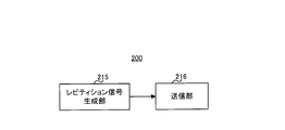
- FIG. 4 is a block diagram illustrating a main configuration of the terminal 200 according to each embodiment of the present disclosure.
- repetition signal generation section 215 performs a plurality of first sequences (to be described later) orthogonal to each other in a plurality of subframes with respect to a signal transmitted by repetition over a plurality of subframes.
- a transmission signal is generated by multiplying each component of any one sequence of (inter-subframe orthogonal code sequences) for each subframe.
- the transmission unit 216 transmits a transmission signal.
- FIG. 5 is a block diagram showing a configuration of base station 100 according to Embodiment 1 of the present disclosure.
- the base station 100 includes a control unit 101, a control signal generation unit 102, an encoding unit 103, a modulation unit 104, an encoding unit 105, a modulation unit 106, a broadcast signal generation unit 107, Signal allocation unit 108, OFDM (Orthogonal Frequency Division Multiplexing) signal generation unit 109, transmission unit 110, antenna 111, reception unit 112, PUCCH extraction unit 113, sequence control unit 114, and repetition signal synthesis reception Unit 115, despreading unit 116, correlation processing unit 117, and ACK / NACK decoding unit 118.
- OFDM Orthogonal Frequency Division Multiplexing
- the control unit 101 transmits, to the terminal 200, a downlink resource (downlink control information allocation resource) for transmitting control information, and a downlink resource (downlink data) for transmitting downlink data indicated by the control information. Assign resources).
- the downlink control information allocation resource is selected in a resource area where an MTC PDCCH or EPDCCH is arranged. Also, the downlink data allocation resource is selected within the resource area where the PDSCH is arranged.
- the control unit 101 assigns different resources to each of the terminals 200.
- the control unit 101 outputs control information such as information on downlink data allocation resources, information on MCS, information on HARQ processes, and information on transmission power control of PUCCH to the control signal generation unit 102. Further, the control unit 101 outputs information related to MCS to the encoding unit 105 and the modulation unit 106. In addition, the control unit 101 instructs the notification signal generation unit 107 to generate a notification signal based on parameters determined in advance for each base station. In addition, the control unit 101 generates information regarding the PUCCH resource and outputs the information to the control signal generation unit 102.
- the control unit 101 generates information related to the inter-subframe orthogonal code sequence (inter-subframe orthogonal code sequence information) for the terminal 200 in which the communication area expansion mode is set.
- the “inter-subframe orthogonal code sequence” is an orthogonal code sequence that is multiplied by a signal transmitted by repetition over a plurality of subframes. That is, each signal of each repeated subframe is multiplied by each component of the inter-subframe orthogonal code sequence.
- ACK / NACK signals from different terminals 200 are spread using inter-subframe orthogonal code sequences corresponding to different sequence numbers (hereinafter referred to as SF-OC Index). That is, the control unit 101 sets any one of a plurality of inter-subframe orthogonal code sequences orthogonal to each other in each of the terminals 200 in a plurality of subframes transmitted by repetition.
- the orthogonal code sequence (see FIG. 1) used in the subframe (each slot) is referred to as “intra-subframe orthogonal code sequence”.
- the control unit 101 outputs the inter-subframe orthogonal code sequence information including the SF-OC index to the control signal generation unit 102 when notifying the SF-OC index using the PDCCH.
- the base station 100 may notify the inter-frame orthogonal code sequence information including SF-OC ⁇ Index to the terminal 200 using an upper layer.
- the control unit 101 when receiving an ACK from the ACK / NACK decoding unit 118, the control unit 101 instructs a transmission data control unit (not shown) to transmit new transmission data.
- the control unit 101 when receiving a NACK or DTX (Discontinuous Transmission) from the ACK / NACK decoding unit 118, the control unit 101 instructs the transmission data control unit to retransmit the previously transmitted transmission data.
- the control signal generation unit 102 uses the information received from the control unit 101 to generate a control signal to be assigned to the PDCCH, and outputs the control signal to the encoding unit 103.
- the encoding unit 103 performs error correction encoding such as a turbo code on the control signal received from the control signal generation unit 102 and outputs the encoded control signal to the modulation unit 104.
- Modulation section 104 performs modulation processing on the control signal received from encoding section 103 and outputs the modulated control signal to signal allocation section 108.
- the encoding unit 105 is obtained by performing error correction encoding such as a turbo code on transmission data (bit sequence, that is, downlink data) according to the encoding rate included in the information related to MCS received from the control unit 101.
- error correction encoding such as a turbo code on transmission data (bit sequence, that is, downlink data) according to the encoding rate included in the information related to MCS received from the control unit 101.
- the encoded bit sequence is output to modulation section 106.
- Modulation section 106 performs data modulation processing on the encoded bit sequence received from encoding section 105 in accordance with the modulation scheme included in the information related to MCS received from control section 101, and sends the resulting data modulated signal to signal allocation section 108. Output.
- the notification signal generation unit 107 generates a notification signal in accordance with an instruction from the control unit 101 and outputs the notification signal to the signal allocation unit 108. Note that the notification signal may be subjected to encoding processing and modulation processing.
- the signal allocation unit 108 receives the control signal received from the modulation unit 104, the data modulation signal received from the modulation unit 106, and the broadcast signal received from the broadcast signal generation unit 107 as downlink resources (downlink data signal allocation resource, downlink control information allocation). And the mapped signal is output to the OFDM signal generation section 109.
- the OFDM signal generation unit 109 generates a time-domain OFDM signal by performing mapping to a subcarrier and IFFT processing on the signal received from the signal allocation unit 108.
- the OFDM signal generation unit 109 outputs the generated OFDM signal to the transmission unit 110.
- Transmitting section 110 performs RF (Radio-Frequency) processing such as D / A (Digital-to-Analog) conversion and up-conversion on the OFDM signal received from OFDM signal generating section 109, and transmits it to terminal 200 via antenna 111. Send a radio signal.
- RF Radio-Frequency
- D / A Digital-to-Analog
- the receiving unit 112 performs RF processing such as down-conversion or A / D (Analog-to-Digital) conversion on the radio signal from the terminal 200 received via the antenna 111, and obtains the baseband SC obtained.
- the FDMA signal is output to the PUCCH extraction unit 113.
- the PUCCH extraction unit 113 converts the SC-FDMA signal received from the reception unit 112 into a frequency domain signal by performing an FFT process. Further, PUCCH extraction section 113 extracts PUCCH from the signal after FFT, and outputs the extracted PUCCH to repetition signal synthesis reception section 115.
- the sequence control unit 114 generates a ZAC sequence, an intra-subframe orthogonal code sequence, and an inter-subframe orthogonal code sequence that may be used for spreading the ACK / NACK signal and the reference signal transmitted from the terminal 200.
- Sequence control section 114 outputs the inter-subframe orthogonal code sequence to repetition signal synthesis reception section 115, outputs the intra-subframe orthogonal code sequence to despreading section 116, and outputs the ZAC sequence to correlation processing section 117.
- a sequence other than the ZAC sequence may be used as long as the sequences are defined with different cyclic shift amounts.
- sequences other than Walsh sequences may be used as long as orthogonal code sequences are orthogonal to each other.
- the repetition signal combining / receiving unit 115 uses the inter-subframe orthogonal code received from the sequence control unit 114 for the PUCCH (ACK / NACK signal and reference signal) transmitted by repetition over a plurality of subframes. / NACK signal and the signal corresponding to the reference signal are combined in phase to generate a combined signal.
- the repetition signal combining / receiving unit 115 outputs the in-phase combined signal to the despreading unit 116.
- sequence control section 114 sequentially outputs a plurality of inter-subframe orthogonal code sequences, and a repetition signal combining / receiving section.
- sequence control section 114 may perform processing (that is, blind processing) using the inter-subframe orthogonal code sequence that is sequentially received until normal in-phase synthesis can be performed.
- sequence control section 114 selects the inter-subframe orthogonal code sequence from among the plurality of inter-subframe orthogonal code sequences.
- the repetition signal combining / receiving unit 115 outputs an in-phase combining process using the received inter-subframe orthogonal code sequence. For example, when the inter-subframe orthogonal code sequence is notified to terminal 200 using PDCCH or EPDCCH for MTC, sequence control unit 114 may receive inter-subframe orthogonal code sequence information from control signal generation unit 102 ( Not shown).
- Despreading section 116 uses the intra-subframe orthogonal code sequence received from sequence control section 114 to despread and despread the signal corresponding to the ACK / NACK signal among the signals received from repetition signal combining reception section 115.
- the spread signal is output to correlation processing section 117.
- Correlation processing section 117 uses the ZAC sequence input from sequence control section 114, and the correlation value between the signal input from despreading section 116 and the ZAC sequence that may be used for primary spreading in terminal 200 Is output to the ACK / NACK decoding unit 118.
- the ACK / NACK decoding unit 118 Based on the correlation value received from the correlation processing unit 117, the ACK / NACK decoding unit 118 indicates whether the ACK / NACK signal transmitted from the terminal 200 indicates either ACK or NACK for the transmitted data, Or it is determined whether it is DTX. The ACK / NACK decoding unit 118 outputs the determination result to the control unit 101.
- FIG. 6 is a block diagram showing a configuration of terminal 200 according to Embodiment 1 of the present disclosure.
- terminal 200 includes antenna 201, receiving section 202, extracting section 203, broadcast signal demodulating section 204, broadcast signal decoding section 205, PDCCH demodulation section 206, PDCCH decoding section 207, and data demodulation.
- the receiving unit 202 performs RF processing such as down-conversion or AD conversion on the radio signal received from the antenna 201 and obtains a baseband OFDM signal.
- Receiving section 202 outputs the OFDM signal to extracting section 203.
- the extraction unit 203 extracts a notification signal from the reception signal received from the reception unit 202 and outputs the notification signal to the notification signal demodulation unit 204.
- the extraction unit 203 obtains the broadcast signal by extracting information mapped to the resource.
- the extracted notification signal includes, for example, information on the system bandwidth.
- the extraction unit 203 extracts a PDCCH or EPDCCH signal for MTC from the reception signal received from the reception unit 202, and outputs it to the PDCCH demodulation unit 206.
- the extraction unit 203 extracts downlink data from the received signal received from the reception unit 202 based on information on downlink data allocation resources addressed to the terminal itself, and outputs the downlink data to the data demodulation unit 208.
- the notification signal demodulation unit 204 demodulates the notification signal received from the extraction unit 203, and outputs the demodulated notification signal to the notification signal decoding unit 205.
- the broadcast signal decoding unit 205 decodes the broadcast signal received from the broadcast signal demodulation unit 204, and obtains a broadcast signal including system bandwidth information and the like.
- the notification signal decoding unit 205 outputs the obtained notification signal to the control unit 210.
- the PDCCH demodulation unit 206 demodulates the MTC PDCCH or EPDCCH signal received from the extraction unit 203, and outputs the demodulated MTC PDCCH or EPDCCH signal to the PDCCH decoding unit 207.
- the PDCCH decoding unit 207 decodes the MDC PDCCH or EPDCCH signal received from the PDCCH demodulation unit 206. Further, PDCCH decoding section 207 determines blindly whether or not the control information included in the decoding result is control information addressed to the terminal itself. After the blind determination, PDCCH decoding section 207 outputs control information addressed to its own terminal to control section 210.
- the data demodulation unit 208 performs demodulation processing on the downlink data received from the extraction unit 203, extracts the data, and outputs the data to the data decoding unit 209.
- the data decoding unit 209 performs error correction processing such as turbo decoding and error detection processing such as CRC (Cyclic Redundancy Check) on the data received from the data demodulation unit 208.
- error correction processing such as turbo decoding
- error detection processing such as CRC (Cyclic Redundancy Check)
- CRC Cyclic Redundancy Check
- Control section 210 identifies PUCCH resources (frequency and code used for primary spreading / secondary spreading) based on a broadcast signal received from broadcast signal decoding section 205 or control information received from PDCCH decoding section 207. . Note that the PUCCH resource may be notified from the base station 100 to the terminal 200 in advance.
- control unit 210 generates a ZAC sequence defined by a cyclic shift amount corresponding to the PUCCH resource to be used, and outputs the ZAC sequence to the primary spreading unit 212.
- control section 210 outputs an intra-subframe orthogonal code sequence corresponding to the PUCCH resource to be used to secondary spreading section 213.
- control section 210 outputs a frequency resource (subcarrier) corresponding to the PUCCH resource to be used to SC-FDMA signal generation section 214.
- the control unit 210 corresponds to the ACK / NACK signal to be transmitted in the same way as LTE Rel. 11 in the PUCCH resource (see FIG. 2) defined by the OC-Index used for the cyclic shift amount and the second spreading.
- the notification may be made in advance via an upper layer.
- the control unit 210 performs a repetition transmission so that the PUCCH is transmitted based on information on the MTC communication area expansion mode such as the number of repetitions.
- the instruction signal generator 215 is instructed.
- the control unit 210 corresponds to the PUCCH resource to be used based on the inter-subframe orthogonal code received from the PDCCH decoding unit 207 or the information on the inter-subframe orthogonal code notified in advance in the upper layer (not shown).
- the inter-subframe orthogonal code sequence is output to repetition signal generator 215. Details of control of the PUCCH resource in the control unit 210 will be described later.
- the ACK / NACK generation unit 211 generates an ACK / NACK signal based on the error detection result received from the data decoding unit 209. Specifically, the ACK / NACK generation unit 211 generates a NACK when an error is detected, and generates an ACK when an error is not detected. The ACK / NACK generation unit 211 outputs the generated ACK / NACK signal to the primary spreading unit 212.
- the primary spreading unit 212 first spreads the ACK / NACK signal and the reference signal using the ZAC sequence and the cyclic shift amount set by the control unit 210, and the ACK / NACK signal and the reference signal after the primary spreading are 2 The data is output to the next diffusion unit 213.
- Secondary spreading section 213 second spreads the ACK / NACK signal and the reference signal using the intra-subframe orthogonal code sequence set by control section 210, and the second spread signal is SC-FDMA signal generating section 214. Output to.
- SC-FDMA signal generation unit 214 uses the frequency resource set by control unit 210 to map the ACK / NACK signal and reference signal received from secondary spreading section 213 to subcarriers, IFFT processing, and CP addition A time-domain SC-FDMA signal is generated by performing processing.
- the SC-FDMA signal generation unit 214 outputs the generated SC-FDMA signal to the repetition signal generation unit 215.
- the repetition signal generation unit 215 performs repetition processing on the SC-FDMA signal received from the SC-FDMA signal generation unit 214, using the repetition count and the inter-subframe orthogonal code sequence set by the control unit 210. , Generating a repetition signal. Also, repetition signal generation section 215 multiplies each component of the inter-subframe orthogonal code sequence for each subframe by the repetition signal transmitted by repetition over a plurality of subframes. The repetition signal generation unit 215 outputs the repetition signal spread by the inter-subframe orthogonal code sequence to the transmission unit 216. If base station 100 has not instructed terminal 200 to operate in the MTC communication area expansion mode, repetition signal generation section 215 performs SC-FDMA signal generation section 214 without performing repetition processing. The SC-FDMA signal received from is output to the transmission unit 216 as it is.
- the transmission unit 216 performs RF processing such as D / A conversion and up-conversion on the signal received from the repetition signal generation unit 215, and transmits a radio signal to the base station 100 via the antenna 201.
- the communication area expansion mode is set for the terminal 200 and the terminal 200 performs repetition transmission of an ACK / NACK signal in PUCCH.
- the repetition rate is set to an integer multiple of X (for example, see Non-Patent Document 6).
- N Rep the number of repetitions is represented as N Rep .
- terminal 200 when performing N Rep repetitions, terminal 200 repeatedly transmits a signal of one subframe over N Rep subframes.
- terminal 200 multiplies each component of the inter-subframe orthogonal code sequence for each subframe in which repetition is performed on the signal to be transmitted by repetition.
- terminal 200 applies each component (C (0) to C (7)) of an inter-subframe orthogonal code sequence to an ACK / NACK signal repeated over 8 consecutive subframes. ) For each subframe.
- each terminal 200 applies each component of any one of a plurality of inter-subframe orthogonal code sequences orthogonal to each other in a plurality of subframes to an ACK / NACK signal transmitted by repetition. Multiply every time to generate a transmission signal. That is, terminal 200 performs primary spreading using any one of a plurality of ZAC sequences that can be separated from each other by different cyclic shift amounts for ACK / NACK signals transmitted in PUCCH, and intra-subframe orthogonal code In addition to secondary spreading using sequences, spreading processing using inter-subframe orthogonal code sequences is performed.
- ACK / NACK signals transmitted from different terminals 200 are sub-frame orthogonal codes corresponding to ZAC sequences defined with different cyclic shift amounts (Cyclic Shift Index) and different sequence numbers (OC Index: Orthogonal Cover Index). Each sequence is spread by using an inter-subframe orthogonal code sequence corresponding to a different orthogonal code sequence number (SF-OC ⁇ ⁇ ⁇ Index).
- the base station 100 receives a signal (including an ACK / NACK signal) from the terminal 200.
- a signal including an ACK / NACK signal
- Each component of the inter-subframe orthogonal code sequence is multiplied for each subframe in the ACK / NACK signal transmitted from the terminal 200 in which the MTC communication area expansion mode is set.
- the base station 100 first performs despreading and correlation processing on the inter-subframe orthogonal code sequence, and then performs despreading and correlation processing on the intra-subframe orthogonal code sequence and the ZAC sequence. Thereby, the base station 100 can separate a plurality of code-multiplexed ACK / NACK signals.
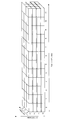
- FIG. 8 shows an example of the PUCCH resource defined by the SF-OC Index, OC Index, and the cyclic shift amount of the ZAC sequence (Cyclic shift Index).
- a Walsh sequence with a sequence length of 4 is used as the inter-subframe orthogonal code sequence
- a Walsh sequence with a sequence length of 4 and a DFT sequence with a sequence length of 3 are used as the intra-subframe orthogonal code sequence.
- a Walsh sequence can be used.
- the inter-subframe orthogonal code sequences (C 0 , C 1 , C 2 , C 3 ) are (1,1,1,1), (1, -1,1, -1). ), (1,1, -1, -1) and (1, -1, -1,1).
- a complex spreading code can be used.
- the inter-subframe orthogonal code sequences (C 0 , C 1 , C 2 , C 3 , C 4 ) are (1,1,1,1,1), (1, e j2 ⁇ / 5 , e j4 ⁇ / 5 , e j6 ⁇ / 5 , e j8 ⁇ / 5 ), (1, e j8 ⁇ / 5 , e j6 ⁇ / 5 , e j4 ⁇ / 5 , e j2 ⁇ / 5 ), (1, e j4 ⁇ / 5 , e j8 ⁇ / 5 , e j2 ⁇ / 5 , e j6 ⁇ / 5 ), (1, e j6 ⁇ / 5 , e j2 ⁇ / 5 , e j8 ⁇ / 5 , e j4 ⁇ / 5 ).
- the inter-subframe orthogonal code sequence sequences defined by different
- Sequence length N SF sub-frame between the orthogonal code sequence for example, (1) may be a pre-cell-specific or group-specific values defined, or (2) the repetition number N Rep same number.
- the cases (1) and (2) will be described in detail.
- the sequence length N SF of the inter-subframe orthogonal code sequence may be set to the same number as the Common SF length (X) as a cell-specific or group-specific value.
- Each terminal 200 is assigned an inter-subframe orthogonal code sequence to be used from the same sequence set of inter-subframe orthogonal code sequences regardless of the number of repetitions of the terminal 200.
- N SF X (four in FIG. 9).
- N SF N Rep (Max) .
- N Rep (Max) is the maximum value (eight in FIG. 10) among the repetition counts set for each terminal.
- an inter-subframe orthogonal code sequence (1,1,1,1) having a sequence length of 4 is an inter-subframe orthogonal code sequence (1,1,1,1,1,1) having a sequence length of 8. 1,1) and (1,1,1,1, -1, -1, -1, -1) are not orthogonal.
- terminal 200 multiplies each component of the orthogonal code sequence for each subframe by a signal transmitted by repetition over a plurality of subframes. For example, when repetition transmission of an ACK / NACK signal in PUCCH, terminal 200 performs spreading processing using an inter-subframe orthogonal code sequence on the ACK / NACK signal in addition to primary spreading and secondary spreading. . As a result, as compared with the case where the inter-subframe orthogonal code sequence is not used (when only primary spreading and secondary spreading are performed; see, for example, FIG. 2), the maximum length of the inter-subframe orthogonal code sequence is doubled. PUCCH resources (see, for example, FIG. 8) can be secured.
- repetition transmission can be performed while suppressing a decrease in frequency utilization efficiency and a shortage of resources.
- the repetition transmission of the ACK / NACK signal in PUCCH has been described as an example.
- a method of multiplying a repetition-transmitted signal by an orthogonal code sequence for each subframe is a channel other than PUCCH (for example, PDCCH for PUSCH, MTC or EPDCCH, PHICH, PCFICH, PDSCH, and PRACH). It is also applicable to.
- the method of multiplying a signal to be transmitted by repetition with an orthogonal code sequence for each subframe is applied to another channel (for example, PUSCH) where primary spreading or secondary spreading is not performed, No primary spreading or secondary spreading is performed, but only spreading processing in a plurality of subframes using inter-subframe orthogonal code sequences is performed.
- Embodiment 2 In this embodiment, a method for reporting an inter-subframe orthogonal code sequence described in Embodiment 1 will be described.
- the basic configuration of the base station and terminal according to this embodiment is the same as that of Embodiment 1, and will be described with reference to FIG. 5 (base station 100) and FIG. 6 (terminal 200).
- terminal 200 multiplies each component of an inter-subframe orthogonal code sequence for each subframe by a signal transmitted by repetition over a plurality of subframes.
- which orthogonal code sequence is used between the base station 100 and the terminal 200 in order for the base station 100 to normally detect the code-multiplexed signal using the inter-subframe orthogonal code sequence. Need to share.
- base station 100 notifies terminal 200 of an inter-subframe orthogonal code sequence (orthogonal code sequence number) used when terminal 200 set in the communication area expansion mode performs repetition transmission.
- an inter-subframe orthogonal code sequence orthogonal code sequence number
- the subframe for starting the repetition transmission of the ACK / NACK signal is a predetermined cell-specific subframe length (Common SF length) X, and the number of repetitions is Let X be an integer multiple.
- each terminal 200 transmits an ACK / NACK signal by repetition using the same PUCCH resource.
- the base station 100 uses, for example, the PDCCH for MTC used to transmit control information related to the PDSCH (downlink data) corresponding to the ACK / NACK signal with the sequence number (SF-OC Index) of the inter-subframe orthogonal code sequence Or you may notify dynamically using the downlink allocation control information (DCI:
- DCI Downlink
- the notification method of the inter-subframe orthogonal code sequence number is dynamically notified using DCI (notification method 2-1), and is notified to semi-static (notification method).
- DCI notification method 2-1
- semi-static notification method
- As notification methods dynamically using DCI six notification methods 2-1-1 to 2-1-6 will be described.
- As notification methods to Semi-static three notification methods 2-2-1 to 2-2-3 will be described.
- ⁇ Notification method 2-1-1> a field for notifying the SF-OC Index is newly added to the DCI format.
- the base station 100 notifies the terminal 200 of the inter-subframe orthogonal code sequence using the newly added field.
- a field for SF-OC index notification may be newly added to the existing DCI format, and SF-OC index notification is newly performed for the DCI format newly defined for the MTC communication area expansion mode.
- a field may be provided.
- RB Resource Block
- RIV Resource Indication Value
- RIV is used as a field used for notification of resource allocation information included in an existing DCI.
- RIV is information notified using the number of bits corresponding to the system bandwidth. For example, in the case of continuous band allocation, RIV is reported using ceil (log 2 (N RB DL (N RB DL +1) / 2)) bits.
- N RB DL indicates a downlink system bandwidth.
- the value of RIV is given by the following equation (1).
- L CRBs represents the number of RBs allocated to terminal 200
- RB START represents the RB having the lowest frequency among the allocated RBs of terminal 200. From the RIV value shown in Equation (1), the number of RBs allocated to terminal 200 and the position of RBs are uniquely determined.
- the number of bits required for RB notification is smaller than when the number of RBs is not limited. Therefore, when limiting the number of RBs, a part of the RIV field can be used for notification of SF-OC Index.
- the base station 100 notifies the inter-subframe orthogonal code sequence information used by the terminal 200 using a part of the RIV field for notifying resource allocation information in the DCI for MTC PDCCH or EPDCCH. That is, when the terminal 200 performs repetition transmission, the base station 100 simultaneously notifies the RB allocation information and the SF-OC index according to the value of the RIV field used for notification of the resource allocation information included in the existing DCI. To do.
- SF-OC Index is associated in advance with each value of a field (RIV field) used for notification of existing downlink resource allocation information included in DCI transmitted from base station 100 to terminal 200, for example.
- a field RIV field
- terminal 200 is notified in advance of a plurality of inter-subframe orthogonal code sequences that can be instructed, and each inter-subframe orthogonal code sequence corresponds to each value of a field used for notification of resource allocation information. Is notified in advance.
- the base station 100 associates a plurality of inter-subframe orthogonal code sequences that can be instructed to the terminal 200 and inter-subframe orthogonal code sequences with each value of a field used for notification of resource allocation information. May be notified in advance using an upper layer or the like, or only a predetermined combination may be used.
- Terminal 200 receives inter-subframe orthogonal code sequence information allocated to a part of a field (RIV field) used for notification of existing resource allocation information. That is, terminal 200 specifies an RB to be used for PDSCH subframe transmission based on the value of the field for resource allocation information notification, and transmits an inter-subframe orthogonal code sequence corresponding to the value to ACK on PUCCH. / NACK signal is determined as an inter-subframe orthogonal code sequence used for repetition transmission.
- RAV field a field
- Base station 100 notifies the number of RBs allocated to terminal 200 and the RB having the lowest frequency among the allocated RBs of terminal 200 using RIV (MTC) given by the following equation (2).
- ceil log 2 (N RB DL L CRBs (MTC) -L CRBs (MTC) (L ) which may be the latter half) of the notification field (existing RIV field) of the resource allocation information included in the existing DCI CRBs (MTC) -1) / 2 )) bits, wherein (a value of 2) RIV given by (MTC), the remaining fields (ceil (log 2 (N RB DL (N RB DL +1) / 2))-ceil (log 2 (N RB DL L CRBs (MTC) -L CRBs (MTC) (L CRBs (MTC) -1) / 2))) bit may be used as the SF-OC Index value.
- MTC RIV
- the SF-OC index is notified using the field (RIV field) used for notifying the existing resource allocation information. This eliminates the need for a new additional bit for notifying SF-OC Index, so that the overhead of the existing DCI format does not increase.
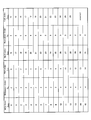
- FIG. 12 shows an example of the correspondence between 5-bit MCS Index, modulation scheme (Modulation Order), and transport block Index (TBS Index).
- the modulation scheme and the transport block index for terminal 200 are uniquely determined by the value of MCS Index shown in FIG.
- the base station 100 notifies the inter-subframe orthogonal code sequence information used by the terminal 200 by using a part of the field for notifying the MCS information in the DCI of MTC PDCCH or EPDCCH. That is, when the terminal 200 performs repetition transmission, the base station 100 notifies the MCS and the SF-OC index at the same time based on the value of the field used for notification of MCS information included in the existing DCI.
- SF-OC Index is associated in advance with each value of a field used for notification of existing downlink MCS information included in the DCI transmitted from the base station 100 to the terminal 200, for example.
- terminal 200 is notified in advance of a plurality of inter-subframe orthogonal code sequences that can be indicated, and each inter-subframe orthogonal code sequence corresponds to each value of a field used for notification of MCS information. Is notified in advance.
- the base station 100 is responsible for associating a plurality of inter-subframe orthogonal code sequences that can be instructed to the terminal 200 and the inter-subframe orthogonal code sequences to each value of the field used for notification of MCS information.
- notification may be made in advance using an upper layer or the like, or only a predetermined combination may be used.
- Terminal 200 receives inter-subframe orthogonal code sequence information allocated to a part of a field used for notification of existing MCS information. That is, terminal 200 specifies MCS to be used for PDSCH subframe transmission based on the value of the field for notification of MCS information, and transmits an inter-subframe orthogonal code sequence corresponding to the value to ACK / It is determined as an inter-subframe orthogonal code sequence used for NACK signal repetition transmission.
- MCS-index 0 to 3 shown in FIG. 12
- the remaining three bits are set as SF-OC. It may be the value of Index.
- the SF-OC Index is notified using the field used for the notification of the existing MCS information. This eliminates the need for a new additional bit for notifying SF-OC Index, so that the overhead of the existing DCI format does not increase.
- a part of the field used for notification of the HARQ process number included in the existing DCI can be used for notification of the SF-OC IV index.
- the base station 100 notifies the inter-subframe orthogonal code sequence information used by the terminal 200 using a part of the field for notifying the HARQ process number in the DCI for MTC PDCCH or EPDCCH. That is, when the terminal 200 performs repetition transmission, the base station 100 simultaneously notifies the HARQ process number and the SF-OC index based on the field value used for notification of the HARQ process number included in the existing DCI. .
- SF-OC Index is associated in advance with each value of a field used for notification of an existing downlink HARQ process number included in the DCI transmitted from the base station 100 to the terminal 200, for example.
- terminal 200 is notified in advance of a plurality of inter-subframe orthogonal code sequences that can be instructed, and each inter-frame orthogonal code corresponding to each value of a field used for HARQ process number notification The series is notified in advance.
- the base station 100 associates a plurality of inter-subframe orthogonal code sequences that can be instructed to the terminal 200 and the inter-subframe orthogonal code sequences with each value of the field used for HARQ process number notification. May be notified in advance using an upper layer or the like, or only a predetermined combination may be used.
- Terminal 200 receives inter-subframe orthogonal code sequence information assigned to a part of a field used for notification of an existing HARQ process number. That is, terminal 200 specifies the HARQ process number used for PDSCH subframe transmission based on the value of the HARQ process number notification field, and uses the PUCCH to generate an inter-subframe orthogonal code sequence corresponding to the value. As an inter-subframe orthogonal code sequence used for repetition transmission of the ACK / NACK signal.
- the base station 100 restricts, for example, two HARQ process numbers of HARQ process numbers 0 and 1 (that is, 1 bit) to the terminal 200 in which the MTC communication area expansion mode is set.
- the first half (or even the second half) of the HARQ process number notification field included in the existing DCI is set as the value of the HARQ process number in the MTC communication area expansion mode, and the remaining two bits are set as SF.
- -It may be the value of OC Index.
- the SF-OC index is notified using the field used for notification of the existing HARQ process number. This eliminates the need for a new additional bit for notifying SF-OC Index, so that the overhead of the existing DCI format does not increase.
- the transmission mode may be limited to the distributed RB transmission mode in order to obtain the frequency diversity effect.
- the transmission mode includes a centralized RB transmission mode (localized RB assignment) in addition to the distributed RB transmission mode. Therefore, in the normal mode, 1 bit is used for notification of the two transmission modes. For example, the transmission mode is notified by localized / distributed VRB assignment flag (1 bit) included in the existing DCI.
- the localized / distributed VRB assignment flag included in the existing DCI can be used for SF-OC Index notification.
- the base station 100 uses all the fields (localized / distributed VRB assignment flag) for notifying the transmission mode in the DCI of PDCCH, and uses the inter-subframe orthogonal code sequence information (SF-OC Index) used by the terminal 200. ).
- SF-OC Index is associated with a localized / distributed VRB assignment flag included in DCI transmitted from base station 100 to terminal 200 in advance, for example.
- terminal 200 is notified in advance of a plurality of inter-subframe orthogonal code sequences that can be instructed, and is also notified in advance of inter-subframe orthogonal code sequences corresponding to each value of localized / distributed VRB assignment flag. Has been.
- the base station 100 is superior to the terminal 200 in association of a plurality of inter-subframe orthogonal code sequences that can be instructed to the terminal 200 and inter-subframe orthogonal code sequences for each value of localized / distributed VRB assignment flag. Notification may be made in advance using a layer or the like, or only a predetermined combination may be used.
- Terminal 200 receives the inter-subframe orthogonal code sequence information assigned to all the fields (localized / distributed VRB assignment flag) used for notification of the existing transmission mode. That is, when performing repetition transmission, terminal 200 sets the distributed RB transmission mode as the transmission mode regardless of the value of localized / distributed VRB assignment flag. Also, terminal 200 determines an inter-subframe orthogonal code sequence corresponding to the value of localized / distributed / VRB / assignment / flag as an inter-subframe orthogonal code sequence used for repetition transmission of an ACK / NACK signal on PUCCH.
- the SF-OC Index is notified using the existing localized / distributed VRB assignment flag. This eliminates the need for a new additional bit for notifying SF-OC Index, so that the overhead of the existing DCI format does not increase.
- TPC transmission power control
- the TPC field included in the existing DCI can be used for the notification of SF-OC Index.
- the base station 100 notifies the inter-subframe orthogonal code sequence information (SF-OC Index) used by the terminal 200 using all of the TCP fields in the MDC PDCCH or EPDCCH DCI.
- SF-OC Index inter-subframe orthogonal code sequence information
- the SF-OC index is associated in advance with each value of the TPC field included in the DCI transmitted from the base station 100 to the terminal 200, for example.
- terminal 200 is notified in advance of a plurality of inter-subframe orthogonal code sequences that can be instructed, and is also notified in advance of inter-subframe orthogonal code sequences corresponding to each value of the TPC field. .
- a plurality of inter-subframe orthogonal code sequences that can be instructed to terminal 200 and the association of the inter-subframe orthogonal code sequences with each value of the TPC field are assigned by base station 100 to terminal 200 such as an upper layer. May be notified in advance, or only a pre-defined combination may be used.
- Terminal 200 receives the inter-subframe orthogonal code sequence information assigned to all existing TPC fields. That is, when performing repetition transmission, terminal 200 sets the transmission power to the maximum power regardless of the value of the TPC field. Also, terminal 200 determines an inter-subframe orthogonal code sequence corresponding to the value of the TPC field as an inter-subframe orthogonal code sequence used for repetition transmission of an ACK / NACK signal on PUCCH.
- the SF-OC Index is notified using the existing TPC field. This eliminates the need for a new additional bit for notifying SF-OC Index, so that the overhead of the existing DCI format does not increase.
- the MTC communication area expansion mode is used. Use fields that may become unnecessary as SF-OC Index notification fields. This eliminates the need to add a new field to the existing DCI format. Therefore, SF-OC Index can be notified without increasing the overhead of the existing DCI format.
- SF-OC®Index may be notified by combining fields used in each notification method. For example, when 3 bits are required for notification of SF-OC Index, localized / distributed VRB assignment flag (1 bit) in notification method 2-1-5 and TPC field (2 bits in notification method 2-1-6) ) And SF-OC Index may be notified.
- the notification method 2-1-1 to notification method 2-1-6 transmission of an ACK / NACK signal in PUCCH has been described as an example.
- the method of dynamically reporting SF-OC Index using DCI is also applicable to channels other than PUCCH (PUSCH, PDCCH for MTC or EPDCCH, PHICH, PCFICH, PDSCH and PRACH).
- the DCI for downlink allocation has been described as an example, but the DCI for uplink allocation may be used.
- Base station 100 notifies the sequence number (SF-OC Index) of the inter-subframe orthogonal code sequence used by terminal 200 using the higher layer signal.
- the SF-OC index is explicitly notified in advance by an upper layer signal transmitted from the base station 100 to the terminal 200.
- Terminal 200 receives an upper layer signal transmitted from base station 100, and uses an inter-subframe orthogonal code sequence indicated in the received upper layer signal as an inter-subframe orthogonal code sequence used for repetition transmission on PUCCH. To do.
- the DCI overhead can be avoided by notifying the SF-OC Index value to the semi-static using the upper layer signal as in the notification method 2-2-1.
- Terminal 200 determines the sequence number (SF-OC Index) of the inter-subframe orthogonal code sequence based on the terminal ID.
- SF-OC Index inter-subframe orthogonal code sequences
- terminal IDs terminal IDs
- SF-OC Index n SF is determined by the following equation (3).
- UEID represents a terminal ID.
- the terminal ID for example, C-RNTI included in the PDCCH may be used.
- terminal 200 converts a sequence corresponding to a terminal ID (C-RNTI) notified from base station 100 from among a plurality of inter-subframe orthogonal code sequences to an inter-subframe orthogonal code sequence used by terminal 200.
- C-RNTI terminal ID
- a hash function which is a function that performs randomization between repetitions in order to prevent continuous PUCCH resource collisions.
- the notification method 2-2-2 by using the RNTI included in the PDCCH or EPDCCH for MTC as the terminal ID, the value of SF-OC Index is notified to the semi-static, so that an additional Since signaling becomes unnecessary, the overhead of DCI can be avoided.
- DCI format 1A of PDCCH is used when requesting transmission of a random access signal. However, 0 or 1 is inserted without using a part of DCI format 1A.
- the field that is not used in the PDCCH or EPDCCH for MTC that requests transmission of a random access signal is used as a field for SF-OC-Index notification. That is, base station 100 uses an MTC PDCCH or EPDCCH DCI field that requests terminal 200 to transmit a random access signal, and uses an inter-subframe orthogonal code sequence that is not used for the request. Notify the sequence number (SF-OC) Index).
- SF-OC Index inter-subframe orthogonal code sequences
- the terminal 200 corresponds to the value of a specific field of the DCI of MDC PDCCH or EPDCCH requesting transmission of the random access signal notified from the base station 100 (field not used for requesting transmission of the random access signal).
- the inter-subframe orthogonal code sequence to be used is determined as the inter-subframe orthogonal code sequence used for repetition transmission on the PUCCH.
- the value of SF-OC Index is set to Semi-static using a part of the existing MDC PDCCH or EPDCCH requesting transmission of a random access signal. Since no additional signaling is required, the overhead of DCI can be avoided.
- notification method 2-2-1 to notification method 2-2-3 transmission of an ACK / NACK signal in PUCCH has been described as an example.
- the method of notifying SF-OC Index to Semi-static is applicable to channels other than PUCCH (PDCCH for PUSCH and MTC or EPDCCH, PHICH, PCFICH, PDSCH and PRACH).
- base station 100 and terminal 200 share in advance an inter-subframe orthogonal code sequence used by terminal 200.
- the base station 100 it is necessary for the base station 100 to perform blind detection of the inter-subframe orthogonal code sequence used in the terminal 200 by making the inter-subframe orthogonal code sequence number used between the base station 100 and the terminal 200 known.
- an increase in complexity of the base station 100 or the terminal 200 can be avoided.
- each functional block used in the description of each of the above embodiments is typically realized as an LSI which is an integrated circuit. These may be individually made into one chip, or may be made into one chip so as to include a part or all of them.
- the name used here is LSI, but it may also be called IC, system LSI, super LSI, or ultra LSI depending on the degree of integration.
- the method of circuit integration is not limited to LSI, and implementation with a dedicated circuit or a general-purpose processor is also possible.
- An FPGA Field Programmable Gate Array
- a reconfigurable processor that can reconfigure the connection and setting of circuit cells inside the LSI may be used.
- the terminal according to the present disclosure multiplies each component of any one of a plurality of first sequences orthogonal to each other and transmits the signal transmitted by repetition over a plurality of subframes for each subframe.
- a configuration including a generation unit that generates a signal and a transmission unit that transmits the transmission signal is adopted.
- the signal is a response signal
- first spreading is performed by first spreading the response signal using any one of a plurality of second sequences defined by different cyclic shift amounts.
- a second spreading unit that secondarily spreads the first spread response signal using any one of a plurality of third sequences orthogonal to each other in a subframe,
- the generation unit repeats the second-order spread response signal over a plurality of subframes, and multiplies the response signal by each component of the first sequence for each subframe.
- the terminal of the present disclosure further includes a reception unit that receives information indicating the first sequence used by the terminal, allocated to a part or all of the field for notifying control information of the downlink control channel. To do.
- control information is resource allocation information, MCS information, HARQ process information, transmission mode information, or transmission power control information.
- the terminal of the present disclosure further includes a receiving unit that receives information indicating the first sequence used by the terminal using an upper layer.
- the generation unit determines the terminal ID notified from the base station from the plurality of first sequences.
- the corresponding sequence is set to the first sequence used by the terminal.
- the number of repetitions is an integral multiple of the repetition start subframe period, and the sequence length of the first sequence is the same as the subframe period.
- the sequence length of the first sequence is the same as the number of repetitions.
- the base station of the present disclosure receives a signal transmitted by repetition over a plurality of subframes, and each signal of one of a plurality of first sequences orthogonal to each other is included in the signal.
- a configuration is provided that includes a receiving unit that is multiplied every time, and a combining unit that combines the signals of the plurality of subframes using any one of the sequences to generate a combined signal.
- the transmission method of the present disclosure multiplies each component of any one of a plurality of first sequences orthogonal to each other for each subframe with respect to a signal transmitted by repetition transmission over a plurality of subframes.
- a configuration including a generation step of generating a transmission signal and a transmission step of transmitting the transmission signal is adopted.
- the reception method of the present disclosure receives a signal transmitted by repetition over a plurality of subframes, and each signal of one of a plurality of first sequences orthogonal to each other is included in the signal.
- a configuration is provided that includes a reception step that is multiplied every time, and a combining step that combines the signals of the plurality of subframes using any one of the sequences to generate a combined signal.
- One embodiment of the present disclosure is useful for a mobile communication system.
- DESCRIPTION OF SYMBOLS 100 Base station 200 Terminal 101,210 Control part 102 Control signal production
Landscapes
- Engineering & Computer Science (AREA)
- Computer Networks & Wireless Communication (AREA)
- Signal Processing (AREA)
- Mobile Radio Communication Systems (AREA)
Abstract
Priority Applications (4)
| Application Number | Priority Date | Filing Date | Title |
|---|---|---|---|
| EP15789011.2A EP3142274B1 (fr) | 2014-05-09 | 2015-03-10 | Terminal, station de base, procédé de transmission et procédé de réception |
| JP2016517801A JP6484611B2 (ja) | 2014-05-09 | 2015-03-10 | 端末、基地局、送信方法及び受信方法 |
| US15/299,366 US10117236B2 (en) | 2014-05-09 | 2016-10-20 | Terminal, base station, transmission method, and reception method |
| US16/144,770 US10484985B2 (en) | 2014-05-09 | 2018-09-27 | Terminal, base station, transmission method, and reception method |
Applications Claiming Priority (2)
| Application Number | Priority Date | Filing Date | Title |
|---|---|---|---|
| JP2014-097420 | 2014-05-09 | ||
| JP2014097420 | 2014-05-09 |
Related Child Applications (1)
| Application Number | Title | Priority Date | Filing Date |
|---|---|---|---|
| US15/299,366 Continuation US10117236B2 (en) | 2014-05-09 | 2016-10-20 | Terminal, base station, transmission method, and reception method |
Publications (1)
| Publication Number | Publication Date |
|---|---|
| WO2015170435A1 true WO2015170435A1 (fr) | 2015-11-12 |
Family
ID=54392299
Family Applications (1)
| Application Number | Title | Priority Date | Filing Date |
|---|---|---|---|
| PCT/JP2015/001292 WO2015170435A1 (fr) | 2014-05-09 | 2015-03-10 | Terminal, station de base, procédé de transmission et procédé de réception |
Country Status (4)
| Country | Link |
|---|---|
| US (2) | US10117236B2 (fr) |
| EP (1) | EP3142274B1 (fr) |
| JP (1) | JP6484611B2 (fr) |
| WO (1) | WO2015170435A1 (fr) |
Cited By (4)
| Publication number | Priority date | Publication date | Assignee | Title |
|---|---|---|---|---|
| WO2017199672A1 (fr) * | 2016-05-20 | 2017-11-23 | パナソニック インテレクチュアル プロパティ コーポレーション オブ アメリカ | Station de base, terminal et procédé de communication |
| WO2018230694A1 (fr) * | 2017-06-15 | 2018-12-20 | シャープ株式会社 | Dispositif de station de base, dispositif terminal et procédé de communication s'y rapportant |
| WO2020003682A1 (fr) * | 2018-06-25 | 2020-01-02 | パナソニック インテレクチュアル プロパティ コーポレーション オブ アメリカ | Station de base, terminal, procédé de réception et procédé d'émission |
| WO2020250447A1 (fr) * | 2019-06-14 | 2020-12-17 | 株式会社Nttドコモ | Terminal et procédé de communication radioélectrique |
Families Citing this family (6)
| Publication number | Priority date | Publication date | Assignee | Title |
|---|---|---|---|---|
| CN106559101B (zh) * | 2015-09-25 | 2019-12-10 | 电信科学技术研究院 | 一种频域扩频、解扩频方法及装置 |
| CN106559198B (zh) * | 2015-09-25 | 2019-09-17 | 电信科学技术研究院 | 一种基于pucch的上行控制信息传输方法及装置 |
| EP3494681B1 (fr) * | 2016-08-10 | 2021-06-30 | Huawei Technologies Co., Ltd. | Signal commun de synchronisation pour une nouvelle porteuse à radio permettant différent espacement de sous-porteuses |
| CN109788557A (zh) * | 2017-11-13 | 2019-05-21 | 珠海市魅族科技有限公司 | 资源分配方法及装置、资源分配的接收方法及装置 |
| US11201702B2 (en) * | 2018-11-13 | 2021-12-14 | At&T Intellectual Property I, L.P. | Facilitating hybrid automatic repeat request reliability improvement for advanced networks |
| US11418278B2 (en) * | 2019-09-23 | 2022-08-16 | Qualcomm Incorporated | Configured dependency between modulation and coding scheme (MCS) and power control |
Citations (3)
| Publication number | Priority date | Publication date | Assignee | Title |
|---|---|---|---|---|
| WO2009041029A1 (fr) * | 2007-09-25 | 2009-04-02 | Panasonic Corporation | Dispositif de communication radio et procédé d'étalement de signal de réponse |
| JP2012520645A (ja) * | 2009-03-17 | 2012-09-06 | ノキア シーメンス ネットワークス オサケユキチュア | 物理アップリンク共有チャネル(pusch)における定期的フィードバック情報の送信の構成 |
| WO2013056741A1 (fr) * | 2011-10-20 | 2013-04-25 | Nokia Siemens Networks Oy | Attribution d'intervalles de temps dans le cdma en liaison montante |
Family Cites Families (6)
| Publication number | Priority date | Publication date | Assignee | Title |
|---|---|---|---|---|
| US6215762B1 (en) * | 1997-07-22 | 2001-04-10 | Ericsson Inc. | Communication system and method with orthogonal block encoding |
| CN101447961A (zh) * | 2007-11-26 | 2009-06-03 | 大唐移动通信设备有限公司 | 宽带无线通信中信号生成和信息传输方法、系统及装置 |
| WO2011112004A2 (fr) * | 2010-03-10 | 2011-09-15 | 엘지전자 주식회사 | Procédé et appareil de transmission d'informations de commande de liaison montante dans système de communication sans fil |
| JP2012222723A (ja) | 2011-04-13 | 2012-11-12 | Sharp Corp | 無線通信システム、移動局装置および基地局装置 |
| JP5847525B2 (ja) | 2011-10-11 | 2016-01-27 | 株式会社Nttドコモ | 無線通信端末、基地局装置、無線通信システム及び無線通信方法 |
| EP2839617B1 (fr) * | 2012-04-17 | 2017-11-08 | Telefonaktiebolaget LM Ericsson (publ) | Procédés et dispositifs pour la transmission de signaux dans un système de télécommunication |
-
2015
- 2015-03-10 JP JP2016517801A patent/JP6484611B2/ja active Active
- 2015-03-10 WO PCT/JP2015/001292 patent/WO2015170435A1/fr active Application Filing
- 2015-03-10 EP EP15789011.2A patent/EP3142274B1/fr active Active
-
2016
- 2016-10-20 US US15/299,366 patent/US10117236B2/en active Active
-
2018
- 2018-09-27 US US16/144,770 patent/US10484985B2/en active Active
Patent Citations (3)
| Publication number | Priority date | Publication date | Assignee | Title |
|---|---|---|---|---|
| WO2009041029A1 (fr) * | 2007-09-25 | 2009-04-02 | Panasonic Corporation | Dispositif de communication radio et procédé d'étalement de signal de réponse |
| JP2012520645A (ja) * | 2009-03-17 | 2012-09-06 | ノキア シーメンス ネットワークス オサケユキチュア | 物理アップリンク共有チャネル(pusch)における定期的フィードバック情報の送信の構成 |
| WO2013056741A1 (fr) * | 2011-10-20 | 2013-04-25 | Nokia Siemens Networks Oy | Attribution d'intervalles de temps dans le cdma en liaison montante |
Non-Patent Citations (6)
| Title |
|---|
| 3RD GENERATION PARTNERSHIP PROJECT;: "Technical Specification Group Radio Access Network;Study on provision of low-cost Machine-Type Communications (MTC) User Equipments (UEs) based on LTE(Release 12", 3GPP TR 36.888 V12.0.0, June 2013 (2013-06-01), pages 42 - 51, XP050692861 * |
| MEDIATEK INC.: "Coverage Analysis of PDSCH and Enhancement Techniques for MTC UEs[ online", 3GPP TSG-RAN WG1#72B RL-131180, April 2013 (2013-04-01), XP050697097, Retrieved from the Internet <URL:http://www.3gpp.org/ftp/tsg_ran/WG1_RL1/TSGR1_ 72b/Docs/Rl-131180.zip>> * |
| PANASONIC: "Multiple subframe code spreading for MTC UEs[ online", 3GPP TSG-RAN WG1#78B RL-144108, October 2014 (2014-10-01), XP050869756, Retrieved from the Internet <URL:http://www.3gpp.org/ftp/tsg_ran/ WG1_RL1/TSGR1_78b/Docs/R1-144108.zip>> * |
| PANASONIC: "Proposal of common coverage enhanced subframe length[ online", 3GPP TSG-RAN WG1#76 RL-140498, 31 January 2014 (2014-01-31), XP050736031, Retrieved from the Internet <URL:http://www.3gpp.org/ ftp/tsg_ran/WG1_RL1/TSGR1_76/Docs/R1-140498. zip> * |
| See also references of EP3142274A4 * |
| ZTE: "Discussion on Traffic Channel Coverage Improvement[ online", 3GPP TSG-RAN WG1#74B RL-134304, October 2013 (2013-10-01), XP050717448, Retrieved from the Internet <URL:http://www.3gpp.org/ ftp/tsg_ran/WG1_RL1/TSGR1_74b/Docs/R1-134304. zip>> * |
Cited By (11)
| Publication number | Priority date | Publication date | Assignee | Title |
|---|---|---|---|---|
| WO2017199672A1 (fr) * | 2016-05-20 | 2017-11-23 | パナソニック インテレクチュアル プロパティ コーポレーション オブ アメリカ | Station de base, terminal et procédé de communication |
| US10999830B2 (en) | 2016-05-20 | 2021-05-04 | Panasonic Intellectual Property Corporation Of America | Base station, terminal, and communication method |
| JP2022188236A (ja) * | 2016-05-20 | 2022-12-20 | パナソニック インテレクチュアル プロパティ コーポレーション オブ アメリカ | 基地局、通信方法及び集積回路 |
| US11659567B2 (en) | 2016-05-20 | 2023-05-23 | Panasonic Intellectual Property Corporation Of America | Base station, terminal, and communication method |
| JP7315771B2 (ja) | 2016-05-20 | 2023-07-26 | パナソニック インテレクチュアル プロパティ コーポレーション オブ アメリカ | 基地局、通信方法及び集積回路 |
| US11943788B2 (en) | 2016-05-20 | 2024-03-26 | Panasonic Intellectual Property Corporation Of America | Base station, terminal, and communication method |
| WO2018230694A1 (fr) * | 2017-06-15 | 2018-12-20 | シャープ株式会社 | Dispositif de station de base, dispositif terminal et procédé de communication s'y rapportant |
| WO2020003682A1 (fr) * | 2018-06-25 | 2020-01-02 | パナソニック インテレクチュアル プロパティ コーポレーション オブ アメリカ | Station de base, terminal, procédé de réception et procédé d'émission |
| JPWO2020003682A1 (ja) * | 2018-06-25 | 2021-08-05 | パナソニック インテレクチュアル プロパティ コーポレーション オブ アメリカPanasonic Intellectual Property Corporation of America | 基地局、端末、受信方法及び送信方法 |
| JP7216089B2 (ja) | 2018-06-25 | 2023-01-31 | パナソニック インテレクチュアル プロパティ コーポレーション オブ アメリカ | 基地局、端末、受信方法及び送信方法 |
| WO2020250447A1 (fr) * | 2019-06-14 | 2020-12-17 | 株式会社Nttドコモ | Terminal et procédé de communication radioélectrique |
Also Published As
| Publication number | Publication date |
|---|---|
| EP3142274A1 (fr) | 2017-03-15 |
| US10484985B2 (en) | 2019-11-19 |
| JPWO2015170435A1 (ja) | 2017-04-20 |
| US20190037543A1 (en) | 2019-01-31 |
| EP3142274A4 (fr) | 2017-05-10 |
| US10117236B2 (en) | 2018-10-30 |
| US20170041911A1 (en) | 2017-02-09 |
| JP6484611B2 (ja) | 2019-03-13 |
| EP3142274B1 (fr) | 2019-07-03 |
Similar Documents
| Publication | Publication Date | Title |
|---|---|---|
| US11838927B2 (en) | Terminal, base station, transmission method, and reception method | |
| JP6484611B2 (ja) | 端末、基地局、送信方法及び受信方法 | |
| US11477768B2 (en) | Terminal, base station, transmission method, and reception method | |
| US10122502B2 (en) | Communication device, transmitting method, and receiving method | |
| JP7016047B2 (ja) | 基地局、通信方法及び集積回路 | |
| JP6799787B2 (ja) | 端末、通信方法及び集積回路 |
Legal Events
| Date | Code | Title | Description |
|---|---|---|---|
| 121 | Ep: the epo has been informed by wipo that ep was designated in this application |
Ref document number: 15789011 Country of ref document: EP Kind code of ref document: A1 |
|
| ENP | Entry into the national phase |
Ref document number: 2016517801 Country of ref document: JP Kind code of ref document: A |
|
| REEP | Request for entry into the european phase |
Ref document number: 2015789011 Country of ref document: EP |
|
| WWE | Wipo information: entry into national phase |
Ref document number: 2015789011 Country of ref document: EP |
|
| NENP | Non-entry into the national phase |
Ref country code: DE |