WO2015163640A1 - 모터의 회전자 - Google Patents
모터의 회전자 Download PDFInfo
- Publication number
- WO2015163640A1 WO2015163640A1 PCT/KR2015/003792 KR2015003792W WO2015163640A1 WO 2015163640 A1 WO2015163640 A1 WO 2015163640A1 KR 2015003792 W KR2015003792 W KR 2015003792W WO 2015163640 A1 WO2015163640 A1 WO 2015163640A1
- Authority
- WO
- WIPO (PCT)
- Prior art keywords
- rotor
- barrier
- motor
- deformation
- deformation preventing
- Prior art date
- Legal status (The legal status is an assumption and is not a legal conclusion. Google has not performed a legal analysis and makes no representation as to the accuracy of the status listed.)
- Ceased
Links
Images


Classifications
-
- H—ELECTRICITY
- H02—GENERATION; CONVERSION OR DISTRIBUTION OF ELECTRIC POWER
- H02K—DYNAMO-ELECTRIC MACHINES
- H02K1/00—Details of the magnetic circuit
- H02K1/06—Details of the magnetic circuit characterised by the shape, form or construction
-
- H—ELECTRICITY
- H02—GENERATION; CONVERSION OR DISTRIBUTION OF ELECTRIC POWER
- H02K—DYNAMO-ELECTRIC MACHINES
- H02K1/00—Details of the magnetic circuit
- H02K1/06—Details of the magnetic circuit characterised by the shape, form or construction
- H02K1/22—Rotating parts of the magnetic circuit
Definitions
- the present invention relates to a rotor of a motor, and more particularly to a rotor of a motor in which the rotor is assembled by shrinking the rotation shaft.
- a motor in general, includes a stator in which a coil that generates magnetism by electricity is rotated, and a rotor that is rotated by mutual electromagnetic force with the stator.
- the motor may be divided into a core type having a rotor and a stator inside and outside along a radial direction of the rotation shaft, and a coreless type in which the rotor and stator are arranged in the axial direction of the rotation shaft.
- the synchronous reluctance motor is operated at a synchronous speed by the reluctance torque generated due to the difference Ld-Lq of the d-axis inductance Ld and the q-axis inductance Lq. It is a rotating synchronous motor.
- Synchronous reluctance motors are cheaper and more reliable than other types of motors, have a very long lifetime, have good electromagnetic properties, but have disadvantages in terms of noise and vibration.
- the conventional synchronous inductive reluctance motor is provided with a stator 120 connected to an external power source and rotatably provided inside the stator 120 to supply power to the stator 120. If it is started by the induced electromotive force is made of a rotor (rotor 110) and the like rotated at a synchronous speed by the reluctance torque (Reluctance Torque).
- the rotor 110 is formed after the shaft hole 115 is formed in the center and a plurality of rotor cores in which a plurality of flux barriers 111 are formed around the shaft hole 115.
- the electron 110 is pressed into the rotating shaft 130 by shrinking and assembled.
- a slip may occur in a process in which the rotor 110 is assembled with the rotating shaft 130.
- the outer diameter of the rotating shaft 130 is made larger than the inner diameter of the rotor 110, and silicon is manufactured.
- the rotor 110 made of steel sheet is coupled to the rotating shaft 130 in the expanded state by heating, and then contracted and fixed after cooling.
- the present invention was created to improve the problems of the rotor of the conventional motor as described above, by minimizing deformation of the outer diameter of the rotor by ensuring a safety factor by uniformly distributing the local stress concentration region occurring inside the rotor barrier
- An object of the present invention is to provide a rotor of a motor capable of reducing torque ripple and reducing noise and vibration by reducing an uneven portion of the air gap between the stator and the rotor.
- the rotor of the motor according to the present invention is a rotor of a motor in which a plurality of rotor cores formed with barriers are stacked and press-fitted to an outer circumferential surface of a rotating shaft, and one side of each rotor core. It characterized in that the deformation preventing hole for preventing the deformation during the press-fit in the formed.
- the barriers are provided with a predetermined distance from each other along the radial direction of the rotation axis to form a barrier group, a plurality of barrier groups provided with a predetermined interval along the circumferential direction
- the deformation preventing hole is provided between the barrier groups.
- the deformation preventing hole is formed symmetrically about the d-axis dividing the space between the barrier groups.
- the deformation preventing hole may be formed in a triangular shape.
- the deformation preventing hole is a first inner wall formed in a direction transverse to the radial direction of the rotation axis, and a barrier provided symmetrically about the d axis and adjacent to the rotation axis It may include a pair of second inner side wall formed in parallel with.
- the first inner wall of the deformation preventing hole may be formed in an arc shape along the circumferential direction of the rotation shaft.
- the barrier may be formed in a straight line across the radial direction of the rotation axis.
- the shortest distance M between two adjacent deformation preventing holes is L / with respect to the length L of the barrier parallel to the first inner wall of the deformation preventing hole. It is preferable to satisfy 3 ⁇ M ⁇ 2L / 3.
- the angle ⁇ between the first inner side wall and the second inner side wall satisfies 10 degrees ⁇ ⁇ 60 degrees.
- the stress concentration portion generated inside the rotor barrier according to the shrink fit process to ensure structural stability and thereby to secure the rotor optimum design margin Since the length of the iron heart can be reduced compared to the same output, the cost of the rotor electrical steel sheet can be reduced and the efficiency can be improved.
- the weight can be reduced, and the stress generated in the rotor can be dispersed to increase the structural stability.
- FIG. 1 is a side view showing a synchronous reluctance motor according to the prior art
- FIG. 2 is a partially enlarged view of the rotor core of FIG. 1.
- Figure 3 is a side view showing a rotor of the motor according to an embodiment of the present invention.
- FIG. 4 is a partially enlarged view of FIG. 3.
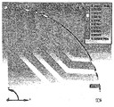
- Figure 5 is a structural analysis showing the rotor stress gradient of the motor according to the prior art.
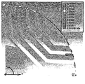
- Figure 6 is a structural analysis showing the rotor stress gradient of the motor according to an embodiment of the present invention.
- Figure 7 is a structural analysis showing the uniformity through the rotor outer diameter deformation analysis of the motor according to the prior art.
- Figure 8 is a structural analysis showing the uniformity through the rotor outer diameter deformation analysis of the motor according to an embodiment of the present invention.
- a rotor of a motor includes a plurality of rotor cores 10 stacked on top of each other, and the stacked rotor cores 10 of the rotating shaft 40 are provided. It is press-fitted to the outer circumference and combined.
- a plurality of barriers 20 are formed at one side of each rotor core 10.
- the barriers 20 are provided with a predetermined distance from each other along the radial direction of the rotation axis 40 to form a barrier group (B), a plurality of barrier groups (B) are provided with a predetermined interval along the circumferential direction. .
- the d-axis is a direction line that bisects the space between the barrier groups B among the direction lines extending along the radial direction from the center of the rotation axis 40, and the q-axis is the barrier 20. It is the center line that bisects them.
- the barrier 20 includes a first barrier 21 formed in a straight line across the radial direction of the rotation shaft 40, and a pair of second barriers 22 provided at both ends of the first barrier 21. .
- the first barrier 21 is formed in a straight line perpendicular to the q axis, and the second barrier 22 is bent at a predetermined angle with respect to the first barrier 21.
- the first barrier 21 and the second barrier 22 may be formed in a curved shape rather than in a straight line, or the first barrier 21 and the second barrier 22 may be formed so as not to be continuous. Included in the category.
- each rotor core 10 is formed with a deformation preventing hole 30 for preventing deformation during press-fitting.
- the deformation preventing hole 30 is provided on the d-axis, and is formed symmetrically about the d-axis.
- the deformation preventing hole 30 is formed of a first inner side wall 31 and a pair of second inner side walls 32 to form a triangular shape as a whole.
- the first inner side wall 31 and the pair of second inner side wall 32 may both be formed of a linear line segment, and in this case, the sum of the inner angles forms a geometric triangle of 180 degrees.
- the first inner side wall 31 and the pair of second inner side wall 32 are both curved, not line segments, and although not geometrically triangular in shape, they are generally included in the scope of the present invention. to be.
- the first inner side wall 31 is formed in an arc shape, and the second inner side wall 32 is formed in a straight line.
- the first inner side wall 31 is formed in a direction transverse to the radial direction of the rotation shaft 40 is formed in an arc shape along the circumferential direction of the rotation shaft 40.
- the first inner side wall 31 is formed to be symmetrically divided about the d axis.
- the second inner wall 32 is formed in parallel with the first barrier 21.
- the second inner wall 32 is also formed in a straight line and provided in parallel with each other.
- the second inner side walls 32 are provided symmetrically with respect to the d axis one by one.
- the deformation preventing hole 30 forms a space between the barrier 20 and the shaft hole 15 so that the portion between the shaft hole 15 and the first inner side wall 21 is not transferred to the barrier 20 even when the portion between the shaft hole 15 and the first inner wall 21 is deformed. do. Therefore, the shape and position of the deformation preventing hole 30 is the main variable to absorb the deformation.
- the length of the barrier 20 that is closest to the rotation axis 40 among the plurality of barriers 20 constituting one barrier group B is referred to as L, and one barrier group B is used.
- the distance between the pair of strain relief holes 30 formed on both sides of the side is M
- the shortest distance M between two adjacent strain prevention holes 30 is L / 3 ⁇ M ⁇ 2L / 3 To satisfy.
- the distance M between the first inner side walls 31 of two adjacent deformation preventing holes 30 is predetermined with respect to the length L of the barrier 20 that is closest to the deformation preventing hole 30. Has a distance ratio of.
- the shortest distance M between the strain preventing holes 30 is smaller than L / 3, the area occupied by the strain preventing holes 30, which is an empty space, is too large and the strength of the rotor core 10 is lowered.
- the deformation is greater than 2L / 3, the area occupied by the deformation preventing hole 30 is too small, so that the effect of reducing deformation during indentation and assembly is reduced, and the stress gradient is uniform in the generation of local stress. The effect is reduced.
- the angle ⁇ between the first inner side wall 31 and the second inner side wall 32 of the deformation preventing hole 30 is preferably greater than 10 degrees and smaller than 60 degrees. That is, the deformation preventing hole 30 is preferably formed with the first inner side wall 31 and the second inner side wall 32 to satisfy 10 degrees ⁇ ⁇ 60 degrees.
- the angle ⁇ is smaller than 10 degrees, the triangular corner where the first inner wall 31 and the second inner wall 32 meet is too sharp, so that the first inner wall 31 is deformed by the deformation of the barrier 20. ) May be affected, and if the angle ( ⁇ ) is greater than 60 degrees, the length of the first inner wall 31 becomes too short, so that the shortest distance (M) condition between the strain preventing holes 30 is determined. By not being able to be satisfied, the effect of reducing deformation is greatly reduced.
- the angle between the angles shown in FIG. 4 is 30 degrees.
- Figure 5 shows the stress gradient of the rotor during the conventional indentation assembly without the deformation prevention hole 30
- Figure 6 shows the stress gradient of the rotor of the present invention to which the deformation prevention hole 30 is applied.
- Table 1 below shows the results of FIGS. 5 and 6.
- a portion indicated in red is a portion having high stress
- a portion indicated in blue is a portion having the lowest stress.
- the stress is 323.6MPa, when the deformation preventing hole 30 is 266.6MPa it can be seen that the stress is reduced by 20% or more.
- strain-resistant holes are applied to the inner side of the core before the strain-resistant holes are applied, thereby dispersing the concentrated stress so that the stress can be uniformly distributed.
- Figure 7 shows the deformation amount during the press-fit assembly of the conventional rotor without the deformation prevention hole 30
- Figure 8 shows the deformation amount of the rotor of the present invention to which the deformation prevention hole 30 is applied.
- Table 2 below shows the results of FIGS. 5 and 6.
- the portion marked in red is the portion where the air gap between the stator and the rotor is the largest, and the deformation amount of the rotor core is the smallest. It is a small part (Min).
- the difference between the maximum value (0.041153 mm) and the minimum value (0.020288 mm) of the air gap is 0.020865 mm.
Landscapes
- Engineering & Computer Science (AREA)
- Power Engineering (AREA)
- Iron Core Of Rotating Electric Machines (AREA)
Abstract
본 발명은 배리어들이 형성된 다수개의 회전자 코어들이 적층되고 회전축의 외주면에 압입되어 결합되는 모터의 회전자에 관한 것으로, 상기 각 회전자 코어의 일측에 압입시의 변형을 방지하기 위한 변형방지홀이 형성되어 조립시 회전자의 변형을 방지함으로써 토크리플을 저감시키고 소음 및 진동을 저감시킬 수 있게 된다.
Description
본 발명은 모터의 회전자에 관한 것으로, 보다 상세하게는 회전자가 회전축에 열박음에 의해 조립되는 모터의 회전자에 관한 것이다.
일반적으로, 모터는 전기에 의해 자기를 발생시키는 코일이 권선된 고정자(stator)와 그 고정자와의 상호 전자기력에 의해 회전되는 회전자(rotor)를 포함한다.
모터는 회전축의 반경방향을 따라 내,외측에 로터와 스테이터를 구비한 코어형(radial type)과, 로터와 스테이터를 회전축의 축방향으로 나열한 코어 레스형(axial type)으로 나눌 수 있다.
코어형 모터 중 동기 릴럭턴스 모터는, d축 인덕턴스(inductance)(Ld) 및 q축 인덕턴스(Lq)의 차(Ld-Lq)에 기인하여 발생되는 릴럭턴스 토크(reluctance torque)에 의해 동기 속도로 회전되는 동기모터이다.
동기식 릴럭턴스 모터는 다른 타입의 모터에 비해 제조가격이 저렴하고 신뢰성이 높으며 수명이 거의 영구적이고 전자계 특성은 우수하나, 소음 및 진동 측면에서는 불리한 단점이 있다.
도 1 내지 도 2를 참조하면, 종래 동기유도 릴럭턴스 모터는 외부 전원과 연결된 고정자(Stator)(120)와, 상기 고정자(120)의 내부에 회전 가능하게 구비되어 고정자(120)에 전원이 인가되면 유도 기전력에 의해 기동된 후 릴럭턴스 토크(Reluctance Torque)에 의해 동기속도로 회전되는 회전자(rotor)(110) 등으로 이루어진다.
회전자(110)는 중앙에 축공(115)이 형성되고 축공(115)의 둘레에 복수의 플럭스 배리어(barrier)(111)가 형성되어 있는 복수의 회전자코어를 절연 적층한 후, 적층된 회전자(110)를 회전축(130)에 열박음에 의해 압입하여 조립한다.
즉, 회전자(110)가 회전축(130)과 조립되는 공정상 슬립(slip)이 발생할 수 있는데, 이를 방지하기 위해 회전자(110)의 내경보다 회전축(130)의 외경을 크게 제조하고, 규소강판으로 된 회전자(110)를 가열하여 팽창시킨 상태에서 회전축(130)에 결합시키고 냉각 후 수축하여 고정시킨다.
이는 견고하게 고정되는 이점은 있으나 열박음 공정에 따라 회전자 배리어 내측에 국부적 응력집중이 발생하고 회전자(110)에 변형이 발생하여 고정자(120)와 회전자(110) 사이의 에어갭(Air gap)이 불균일해지고, 그로 인해 토크리플과 소음 및 진동이 증가하는 문제점이 있었다.
고정자(120)와 회전자(110) 사이의 에어갭은 회전자(110)의 변형분포에 따라 원주방향을 따라 편차가 크게 발생하므로, 종래에는 회전자(110)의 외경을 사포로 연마하는 등의 방법이 사용되기도 하였으나 이는 불균일성을 해소하는 근본 대책이 되지 못하고 있다.
본 발명은 상기한 바와 같은 종래 모터의 회전자가 가지는 문제점들을 개선하기 위해 창출된 것으로, 회전자 배리어 내측에 발생하는 국부적 응력집중부위를 균일 분포시켜 안전률을 확보함으로써 회전자 외경의 변형을 최소화하고 고정자와 회전자간의 에어갭이 불균일한 부분을 감소시켜 토크리플을 저감시키고 소음 및 진동을 저감시킬 수 있는 모터의 회전자를 제공함에 그 목적이 있다.
상기한 바와 같은 목적을 달성하기 위하여 본 발명에 의한 모터의 회전자는, 배리어들이 형성된 다수개의 회전자 코어들이 적층되고 회전축의 외주면에 압입되어 결합되는 모터의 회전자로서, 상기 각 회전자 코어의 일측에 압입시의 변형을 방지하기 위한 변형방지홀이 형성된 것을 특징으로 한다.
본 발명의 실시예에 따른 모터의 회전자에 있어서, 상기 배리어들은 회전축의 반경방향을 따라 서로 소정간격을 두고 구비되어 배리어군을 이루고, 상기 배리어군이 원주방향을 따라 소정간격을 두고 다수개 구비되며, 상기 변형방지 홀은 배리어군들의 사이에 구비된다.
본 발명의 실시예에 따른 모터의 회전자에 있어서, 상기 변형방지홀은 상기 배리어군들의 사이 공간을 이등분하는 d축을 중심으로 대칭되게 형성된다.
본 발명의 실시예에 따른 모터의 회전자에 있어서, 상기 변형방지홀은 삼각형상으로 형성될 수 있다.
본 발명의 실시예에 따른 모터의 회전자에 있어서, 상기 변형방지홀은 회전축의 반경방향을 가로지르는 방향으로 형성되는 제1내측벽, 및 상기 d축을 중심으로 대칭되게 구비되고 회전축에 인접하는 배리어와 평행하게 형성되는 1쌍의 제2내측벽을 포함할 수 있다.
본 발명의 실시예에 따른 모터의 회전자에 있어서, 상기 변형방지홀의 제1내측벽은 회전축의 원주방향을 따라 원호형상으로 형성될 수 있다.
본 발명의 실시예에 따른 모터의 회전자에 있어서, 상기 배리어는 회전축의 반경방향을 가로질러 직선으로 형성될 수 있다.
본 발명의 실시예에 따른 모터의 회전자에 있어서, 인접하는 2개의 변형방지홀 사이의 최단거리(M)는 그 변형방지홀의 제1내측벽과 평행한 배리어의 길이(L)에 대하여 L/3 < M < 2L/3을 만족하는 것이 바람직하다.
본 발명의 실시예에 따른 모터의 회전자에 있어서, 상기 제1내측벽과 제2내측벽이 이루는 사이각(α)은 10도 < α< 60도를 만족시키는 것이 바람직하다.
본 발명의 특징 및 이점들은 첨부도면에 의거한 다음의 상세한 설명으로 더욱 명백해질 것이다.
이상에서 설명한 바와 같이 본 발명에 따른 모터의 회전자에 의하면, 열박음 공정에 따른 회전자 배리어 내측에 발생하는 응력집중부위를 균일하게 하여 구조안정성을 확보하고 이를 통해 회전자 최적설계 마진을 확보하여 동일 출력 대비 철심장 길이를 축소가능하므로 회전자 전기강판의 원가를 절감할 수 있으며 효율을 향상시킬 수 있다.
그리고, 회전자의 변형을 방지하여 회전자와 고정자간에 에어갭이 균일하게 분포할 수 있게 하고, 토크리플을 저감시킬 수 있을 뿐만 아니라 소음 및 진동을 저감시킬 수 있는 효과가 있다.
본 발명에 의하면, 회전자에 홀을 형성함으로써 중량을 저감시킬 수 있고, 회전자에 발생하는 응력을 분산시켜 구조적 안정성을 높일 수 있는 효과가 있다.
도 1은 종래의 기술에 따른 동기 릴럭턴스 모터를 나타낸 일측면도.
도 2는 도 1의 회전자 코어를 나타낸 부분 확대도.
도 3은 본 발명의 일 실시예에 따른 모터의 회전자를 나타낸 일측면도.
도 4는 도 3의 부분 확대도.
도 5는 종래의 기술에 따른 모터의 회전자 응력구배를 나타낸 구조해석도.
도 6은 본 발명의 일 실시예에 따른 모터의 회전자 응력구배를 나타낸 구조해석도.
도 7은 종래의 기술에 따른 모터의 회전자 외경 변형량 해석을 통한 균일도를 나타낸 구조해석도.
도 8은 본 발명의 실시예에 따른 모터의 회전자 외경 변형량 해석을 통한 균일도를 나타낸 구조해석도.
이하, 첨부된 도면을 참조하여 본 발명의 바람직한 실시예를 상세히 설명하기로 한다.
도 3 내지 도 4를 참조하면, 본 발명의 일 실시예에 따른 모터의 회전자는, 다수개의 회전자 코어(10)들이 적층되어 구비되고, 적층된 회전자 코어(10)들이 회전축(40)의 외주면에 압입되어 결합된다.
상기 각 회전자 코어(10)의 일측에는 다수개의 배리어(20)들이 형성되어 있다.
상기 배리어(20)들은 회전축(40)의 반경방향을 따라 서로 소정간격을 두고 구비되어 배리어군(B)을 이루고, 상기 배리어군(B)이 원주방향을 따라 소정간격을 두고 다수개 구비되어 있다.
도 3에 도시된 바와 같이, d축은 상기 회전축(40)의 중심으로부터 반경반향을 따라 연장되는 방향선 중 상기 배리어군(B)들의 사이 공간을 이등분하는 방향선이고, q축은 상기 배리어(20)들을 이등분하는 중심선이다.
상기 배리어(20)는 회전축(40)의 반경방향을 가로질러 직선으로 형성되는 제1배리어(21), 및 제1배리어(21)의 양단에 구비되는 1쌍의 제2배리어(22)로 이루어진다.
상기 제1배리어(21)는 q축과 수직한 직선형상으로 형성되고, 제2배리어(22)는 제1배리어(21)에 대하여 소정의 각도로 절곡되어 형성되어 있다. 제1배리어(21)와 제2배리어(22)는 직선이 아닌 곡선 형상으로 형성되거나 제1배리어(21)와 제2배리어(22)가 연속하지 않게 형성될 수 있으며, 이 경우 모두 본 발명의 범주에 포함된다.
상기 각 회전자 코어(10)의 일측에 압입시의 변형을 방지하기 위한 변형방지홀(30)이 형성되어 있다.
상기 변형방지홀(30)은 d축 상에 구비되되, 그 d축을 중심으로 대칭되게 형성되어 있다.
상기 변형방지홀(30)은 제1내측벽(31) 및 1쌍의 제2내측벽(32)으로 이루어져 전체적으로 삼각형상을 이룬다. 여기서, 상기 제1내측벽(31)과 1쌍의 제2내측벽(32)은 모두 직선형태의 선분으로 이루어질 수 있고, 이 경우 내각의 합이 180도인 기하학적 삼각형을 형성하게 된다. 또한, 제1내측벽(31)과 1쌍의 제2내측벽(32)이 모두 선분이 아닌 곡선형태로 이루어져 기하학적인 삼각형은 아닐지라도 전체적으로 삼각형상을 띠는 것도 본 발명의 범주에 포함됨은 물론이다.
본 실시예에서 제1내측벽(31)은 원호형상으로 형성되고, 제2내측벽(32)은 직선으로 형성되어 있다.
상기 제1내측벽(31)은 회전축(40)의 반경방향을 가로지르는 방향으로 형성되되 회전축(40)의 원주방향을 따라 원호형상으로 형성되어 있다. 제1내측벽(31)은 d축을 중심으로 대칭되게 분할되어 형성된다.
상기 제2내측벽(32)은 상기 제1배리어(21)와 평행하게 형성된다. 제1배리어(21)가 직선으로 형성된 경우 제2내측벽(32)도 직선으로 형성되어 서로 평행하게 구비된다. 제2내측벽(32)은 d축을 중심으로 하나씩 대칭되게 구비되어 있다.
변형방지홀(30)은 배리어(20)와 축공(15) 사이에 공간을 형성하여 압입시 축공(15)과 제1내측벽(21) 사이의 부분이 변형되더라도 배리어(20)쪽으로 전달되지 않게 한다. 따라서, 변형방지홀(30)의 형상과 위치가 변형을 흡수하는 주요 변수가 된다.
도 4에 도시된 바와 같이, 하나의 배리어군(B)을 이루는 다수개의 배리어(20)들 중 회전축(40)에 가장 인접하는 배리어(20)의 길이를 L이라 하고, 하나의 배리어군(B)의 양쪽에 형성된 1쌍의 변형방지홀(30) 사이의 거리를 M이라고 할 때, 인접하는 2개의 변형방지홀(30) 사이의 최단거리(M)는 L/3 < M < 2L/3을 만족한다.
즉, 인접하는 2개의 변형방지홀(30)의 제1내측벽(31)들 사이의 거리(M)은 그 변형방지홀(30)과 가장 인접한 배리어(20)의 길이(L)에 대하여 소정의 거리비를 가진다. 변형방지홀(30)들 사이의 최단거리(M)가 L/3보다 작을 경우에는 빈공간인 변형방지홀(30)이 차지하는 면적이 지나치게 커 회전자 코어(10)의 강도를 오히려 저하시켜 구조적인 변형을 가져올 수 있고, 2L/3보다 큰 경우에는 변형방지홀(30)이 차지하는 면적이 지나치게 작아져 압입조립시의 변형을 감소시키는 효과가 저감되고 국부적 응력의 발생을 응력구배가 균일하도록 하는 효과가 저감된다.
도 4에 도시된 바와 같이, 변형방지홀(30)의 제1내측벽(31)과 제2내측벽(32) 사이의 사이각(α)은 10도보다 크고 60도보다 작은 것이 바람직하다. 즉, 변형방지홀(30)은 10도 < α < 60도를 만족하도록 제1내측벽(31)과 제2내측벽(32)이 형성되는 것이 바람직하다.
사이각(α)이 10도보다 작을 경우에는 제1내측벽(31)과 제2내측벽(32)이 만나는 삼각형상의 모서리가 지나치게 뾰족하여 제1내측벽(31)이 변형에 의해 배리어(20)쪽이 영향을 받을 수 있고, 사이각(α)이 60도보다 클 경우에는 제1내측벽(31)의 길이가 지나치게 짧아져 변형방지홀(30)들 사이의 최단거리(M) 조건을 만족시킬 수 없게 됨으로써 변형을 감소시키는 효과가 크게 저감된다. 도 4에 도시된 사이각은 30도이다.
도 5는 변형방지홀(30)이 없는 종래 압입조립시 회전자의 응력구배를 나타낸 것이고, 도 6은 변형방지홀(30)이 적용된 본 발명의 회전자의 응력구배를 나타낸 것이다. 아래의 [표1]은 도 5 및 도 6의 결과를 나타낸 것이다.
표 1 
도 5 및 도 6을 참조하면, 적색으로 표시된 부분이 응력이 높은 부분이고, 파란색으로 표시된 부분이 응력이 가장 낮은 부분이다.
변형방지홀(30)이 없는 경우에는 응력이 323.6MPa 이며, 변형방지홀(30)이 있는 경우는 266.6MPa로 종래대비 20%이상 응력이 감소한 것을 알 수 있다.
이와 같이 변형방지홀 적용 전 코어내측에 변형방지홀을 적용하여 집중응력을 분산시켜 응력을 균일하게 분포시킬 수 있게 된다.
이를 통해 회전자 베리어 설계마진을 확보하여 최하단 베리어 이격거리를 줄여 동일출력대비 회전자의 철심장 길이를 축소할 수 있게 되고, 그로 인해 회전자 전기강판의 원가를 절감할 수 있으며 효율을 향상시킬수 있게 된다.
도 7은 변형방지홀(30)이 없는 종래 회전자의 압입조립시 변형량을 나타낸 것이고, 도 8은 변형방지홀(30)이 적용된 본 발명의 회전자의 변형량을 나타낸 것이다. 아래의 [표2]는 도 5 및 도 6의 결과를 나타낸 것이다.
표 2 
도 7 및 도 8을 참조하면, 적색으로 표시된 부분이 고정자와 회전자 사이의 에어갭이 가장 큰 부분(Max)으로 회전자 코어의 변형량이 가장 작은 부분이고, 파란색으로 표시된 부분의 에어갭이 가장 작은 부분(Min)이다.
변형방지홀(30)이 없는 경우에는 에어갭의 최대치(0.041153mm)와 최소치(0.020288mm)의 차이가 0.020865mm이다.
반면, 도 8 및 [표2]을 참조하면, 변형방지홀(30)이 적용된 본 발명의 경우에는 최대치(0.023735)와 최소치(0.012166mm)의 차이가 0.011569mm에 불과하다. 이는 종래 대비 편차가 44.5% 감소함과 동시에 최대치와 최대치가 모두 감소한 것으로 회전자 코어(10)의 외주면 변형이 균일하게 이루어졌을 뿐만 아니라 변형이 전체적으로 현저하게 감소하였음을 의미한다. 이와 같이 에어갭의 균일도가 향상되면 모터의 토크리플 및 소음, 진동이 저감되어 모터의 성능이 향상된다.
이상 본 발명을 구체적인 실시예를 통하여 상세히 설명하였으나, 이는 본 발명을 구체적으로 설명하기 위한 것으로, 본 발명은 이에 한정되지 않으며, 본 발명은 본 발명의 기술적 사상 내에서 당해 분야의 통상의 지식을 가진 자에 의해 그 변형이나 개량이 가능함은 명백하다.
본 발명의 단순한 변형 내지 변경은 모두 본 발명의 영역에 속하는 것으로 본 발명의 구체적인 보호 범위는 첨부된 특허청구범위에 의하여 명확해질 것이다.
Claims (8)
- 배리어들이 형성된 다수개의 회전자 코어들이 적층되고 회전축의 외주면에 압입되어 결합되는 모터의 회전자에 있어서,상기 각 회전자 코어의 일측에 압입시 배리어 내측의 응력분산 및 변형을 방지하기 위한 변형방지홀이 형성된 것을 특징으로 하는 모터의 회전자.
- 제1항에 있어서,상기 배리어들은 회전축의 반경방향을 따라 서로 소정간격을 두고 구비되어 배리어군을 이루고, 상기 배리어군이 원주방향을 따라 소정간격을 두고 다수개 구비되며,상기 변형방지홀은 배리어군들의 사이에 구비되는 것을 특징으로 하는 모터의 회전자.
- 제2항에 있어서, 상기 변형방지홀은,상기 배리어군들의 사이 공간을 이등분하는 d축을 중심으로 대칭되게 형성된 것을 특징으로 하는 모터의 회전자.
- 제3항에 있어서, 상기 변형방지홀은,삼각형상으로 형성된 것을 특징으로 하는 모터의 회전자.
- 제4항에 있어서, 상기 변형방지홀은,회전축의 반경방향을 가로지르는 방향으로 형성되는 제1내측벽; 및상기 d축을 중심으로 대칭되게 구비되고, 회전축에 인접하는 배리어와 평행하게 형성되는 1쌍의 제2내측벽;을 포함하는 것을 특징으로 하는 모터의 회전자.
- 제5항에 있어서, 상기 변형방지홀의 제1내측벽은,회전축의 원주방향을 따라 원호형상으로 형성된 것을 특징으로 하는 모터의 회전자.
- 제5항에 있어서,상기 배리어는 회전축의 반경방향을 가로질러 직선으로 형성되고,인접하는 2개의 변형방지홀 사이의 최단거리(M)는 그 변형방지홀의 제1내측벽과 인접한 배리어의 길이(L)에 대하여 L/3 < M < 2L/3을 만족하는 것을 특징으로 하는 모터의 회전자.
- 제5항에 있어서,상기 제1내측벽과 제2내측벽이 이루는 사이각(α)은 10도 < α< 60도를 만족시키는 것을 특징으로 하는 모터의 회전자.
Applications Claiming Priority (2)
| Application Number | Priority Date | Filing Date | Title |
|---|---|---|---|
| KR1020140047512A KR101611492B1 (ko) | 2014-04-21 | 2014-04-21 | 모터의 회전자 |
| KR10-2014-0047512 | 2014-04-21 |
Publications (1)
| Publication Number | Publication Date |
|---|---|
| WO2015163640A1 true WO2015163640A1 (ko) | 2015-10-29 |
Family
ID=54332743
Family Applications (1)
| Application Number | Title | Priority Date | Filing Date |
|---|---|---|---|
| PCT/KR2015/003792 Ceased WO2015163640A1 (ko) | 2014-04-21 | 2015-04-15 | 모터의 회전자 |
Country Status (2)
| Country | Link |
|---|---|
| KR (1) | KR101611492B1 (ko) |
| WO (1) | WO2015163640A1 (ko) |
Cited By (4)
| Publication number | Priority date | Publication date | Assignee | Title |
|---|---|---|---|---|
| US20220109339A1 (en) * | 2020-10-01 | 2022-04-07 | Mando Corporation | Electric motor having stacked different rotor segments and method for designing the same |
| US11437900B2 (en) | 2019-12-19 | 2022-09-06 | Black & Decker Inc. | Modular outer-rotor brushless motor for a power tool |
| US11757330B2 (en) | 2019-12-19 | 2023-09-12 | Black & Decker, Inc. | Canned outer-rotor brushless motor for a power tool |
| US12176794B2 (en) | 2021-11-19 | 2024-12-24 | Black & Decker Inc. | Outer-rotor brushless motor for a power tool |
Citations (4)
| Publication number | Priority date | Publication date | Assignee | Title |
|---|---|---|---|---|
| KR20030059629A (ko) * | 2002-01-03 | 2003-07-10 | 엘지전자 주식회사 | 동기 리럭턴스 모터의 회전자구조 |
| KR100643903B1 (ko) * | 2005-10-12 | 2006-11-10 | 주식회사 대우일렉트로닉스 | 동기 릴럭턴스 모터의 회전자구조 |
| JP2011223713A (ja) * | 2010-04-07 | 2011-11-04 | Mitsubishi Electric Corp | リラクタンスモータ |
| KR20130028142A (ko) * | 2010-07-02 | 2013-03-18 | 에이비비 리써치 리미티드 | 스포크 개구부를 구비하는 로터 디스크 |
-
2014
- 2014-04-21 KR KR1020140047512A patent/KR101611492B1/ko active Active
-
2015
- 2015-04-15 WO PCT/KR2015/003792 patent/WO2015163640A1/ko not_active Ceased
Patent Citations (4)
| Publication number | Priority date | Publication date | Assignee | Title |
|---|---|---|---|---|
| KR20030059629A (ko) * | 2002-01-03 | 2003-07-10 | 엘지전자 주식회사 | 동기 리럭턴스 모터의 회전자구조 |
| KR100643903B1 (ko) * | 2005-10-12 | 2006-11-10 | 주식회사 대우일렉트로닉스 | 동기 릴럭턴스 모터의 회전자구조 |
| JP2011223713A (ja) * | 2010-04-07 | 2011-11-04 | Mitsubishi Electric Corp | リラクタンスモータ |
| KR20130028142A (ko) * | 2010-07-02 | 2013-03-18 | 에이비비 리써치 리미티드 | 스포크 개구부를 구비하는 로터 디스크 |
Cited By (6)
| Publication number | Priority date | Publication date | Assignee | Title |
|---|---|---|---|---|
| US11437900B2 (en) | 2019-12-19 | 2022-09-06 | Black & Decker Inc. | Modular outer-rotor brushless motor for a power tool |
| US11757330B2 (en) | 2019-12-19 | 2023-09-12 | Black & Decker, Inc. | Canned outer-rotor brushless motor for a power tool |
| US12218567B2 (en) | 2019-12-19 | 2025-02-04 | Black & Decker Inc. | Power tool having an outer-rotor brushless motor |
| US20220109339A1 (en) * | 2020-10-01 | 2022-04-07 | Mando Corporation | Electric motor having stacked different rotor segments and method for designing the same |
| US12132354B2 (en) * | 2020-10-01 | 2024-10-29 | Hl Mando Corporation | Electric motor having stacked different rotor segments and method for designing the same |
| US12176794B2 (en) | 2021-11-19 | 2024-12-24 | Black & Decker Inc. | Outer-rotor brushless motor for a power tool |
Also Published As
| Publication number | Publication date |
|---|---|
| KR20150121774A (ko) | 2015-10-30 |
| KR101611492B1 (ko) | 2016-04-12 |
Similar Documents
| Publication | Publication Date | Title |
|---|---|---|
| EP3989403A1 (en) | Rotor core lamination, rotor core, rotor, permanent magnet synchronous electric motor, and related product | |
| WO2016182117A1 (en) | Stack structure of rotor core | |
| CN102484402B (zh) | 转子、旋转电机、车辆、升降机、流体设备以及加工机 | |
| WO2015163640A1 (ko) | 모터의 회전자 | |
| WO2013133474A1 (ko) | 매립형 영구자석 전동기 | |
| CN205829324U (zh) | 电机和电动汽车 | |
| CN110875655A (zh) | 电机转子、电机以及电动汽车 | |
| WO2018110971A1 (ko) | 라인기동식 동기형 릴럭턴스 전동기 및 그 회전자 | |
| WO2018044038A1 (ko) | 라인기동식 동기형 릴럭턴스 전동기 및 그 회전자 | |
| WO2014104824A1 (ko) | 고 토크 제공구조를 갖는 매립형 영구자석 동기 전동기의 회전자 | |
| CN205377491U (zh) | 电机转子及永磁电机 | |
| CN107437856A (zh) | 电机转子、电机和电动汽车 | |
| CN111654133A (zh) | 一种电机转子冲片以及电机转子总成系统 | |
| CN210669831U (zh) | 电滚筒永磁同步电动机 | |
| CN112653274B (zh) | 转子冲片及永磁电机转子 | |
| JP2024514331A (ja) | モータ | |
| CN206004437U (zh) | 永磁电机转子及永磁电机 | |
| JP2022121978A (ja) | 回転電機 | |
| CN113364177B (zh) | 斜极转子、电机、压缩机及空调器 | |
| CN119813591A (zh) | 转子冲片、电机、压缩机和制冷设备 | |
| KR102769825B1 (ko) | 로터 및 이를 구비한 전동기 | |
| KR101660893B1 (ko) | 전동기의 회전자 | |
| CN114884239A (zh) | 一种转子结构及应用其的电机 | |
| WO2020101440A1 (en) | Variable motor laminations | |
| CN118432392B (zh) | 永磁同步转子冲片、永磁同步转子和永磁同步电机 |
Legal Events
| Date | Code | Title | Description |
|---|---|---|---|
| 121 | Ep: the epo has been informed by wipo that ep was designated in this application |
Ref document number: 15782387 Country of ref document: EP Kind code of ref document: A1 |
|
| NENP | Non-entry into the national phase |
Ref country code: DE |
|
| 122 | Ep: pct application non-entry in european phase |
Ref document number: 15782387 Country of ref document: EP Kind code of ref document: A1 |