WO2015163171A1 - Image processing apparatus and method and surgical operation system - Google Patents
Image processing apparatus and method and surgical operation system Download PDFInfo
- Publication number
- WO2015163171A1 WO2015163171A1 PCT/JP2015/061311 JP2015061311W WO2015163171A1 WO 2015163171 A1 WO2015163171 A1 WO 2015163171A1 JP 2015061311 W JP2015061311 W JP 2015061311W WO 2015163171 A1 WO2015163171 A1 WO 2015163171A1
- Authority
- WO
- WIPO (PCT)
- Prior art keywords
- processing
- image
- range
- filter
- vertical direction
- Prior art date
Links
Images


Classifications
-
- G—PHYSICS
- G09—EDUCATION; CRYPTOGRAPHY; DISPLAY; ADVERTISING; SEALS
- G09G—ARRANGEMENTS OR CIRCUITS FOR CONTROL OF INDICATING DEVICES USING STATIC MEANS TO PRESENT VARIABLE INFORMATION
- G09G3/00—Control arrangements or circuits, of interest only in connection with visual indicators other than cathode-ray tubes
- G09G3/20—Control arrangements or circuits, of interest only in connection with visual indicators other than cathode-ray tubes for presentation of an assembly of a number of characters, e.g. a page, by composing the assembly by combination of individual elements arranged in a matrix no fixed position being assigned to or needed to be assigned to the individual characters or partial characters
- G09G3/2085—Special arrangements for addressing the individual elements of the matrix, other than by driving respective rows and columns in combination
- G09G3/2088—Special arrangements for addressing the individual elements of the matrix, other than by driving respective rows and columns in combination with use of a plurality of processors, each processor controlling a number of individual elements of the matrix
-
- H—ELECTRICITY
- H04—ELECTRIC COMMUNICATION TECHNIQUE
- H04N—PICTORIAL COMMUNICATION, e.g. TELEVISION
- H04N23/00—Cameras or camera modules comprising electronic image sensors; Control thereof
-
- G—PHYSICS
- G06—COMPUTING; CALCULATING OR COUNTING
- G06T—IMAGE DATA PROCESSING OR GENERATION, IN GENERAL
- G06T1/00—General purpose image data processing
- G06T1/20—Processor architectures; Processor configuration, e.g. pipelining
-
- G—PHYSICS
- G06—COMPUTING; CALCULATING OR COUNTING
- G06T—IMAGE DATA PROCESSING OR GENERATION, IN GENERAL
- G06T7/00—Image analysis
- G06T7/10—Segmentation; Edge detection
- G06T7/11—Region-based segmentation
-
- G—PHYSICS
- G09—EDUCATION; CRYPTOGRAPHY; DISPLAY; ADVERTISING; SEALS
- G09G—ARRANGEMENTS OR CIRCUITS FOR CONTROL OF INDICATING DEVICES USING STATIC MEANS TO PRESENT VARIABLE INFORMATION
- G09G3/00—Control arrangements or circuits, of interest only in connection with visual indicators other than cathode-ray tubes
- G09G3/20—Control arrangements or circuits, of interest only in connection with visual indicators other than cathode-ray tubes for presentation of an assembly of a number of characters, e.g. a page, by composing the assembly by combination of individual elements arranged in a matrix no fixed position being assigned to or needed to be assigned to the individual characters or partial characters
- G09G3/34—Control arrangements or circuits, of interest only in connection with visual indicators other than cathode-ray tubes for presentation of an assembly of a number of characters, e.g. a page, by composing the assembly by combination of individual elements arranged in a matrix no fixed position being assigned to or needed to be assigned to the individual characters or partial characters by control of light from an independent source
- G09G3/36—Control arrangements or circuits, of interest only in connection with visual indicators other than cathode-ray tubes for presentation of an assembly of a number of characters, e.g. a page, by composing the assembly by combination of individual elements arranged in a matrix no fixed position being assigned to or needed to be assigned to the individual characters or partial characters by control of light from an independent source using liquid crystals
- G09G3/3611—Control of matrices with row and column drivers
- G09G3/3622—Control of matrices with row and column drivers using a passive matrix
- G09G3/3644—Control of matrices with row and column drivers using a passive matrix with the matrix divided into sections
-
- G—PHYSICS
- G09—EDUCATION; CRYPTOGRAPHY; DISPLAY; ADVERTISING; SEALS
- G09G—ARRANGEMENTS OR CIRCUITS FOR CONTROL OF INDICATING DEVICES USING STATIC MEANS TO PRESENT VARIABLE INFORMATION
- G09G5/00—Control arrangements or circuits for visual indicators common to cathode-ray tube indicators and other visual indicators
- G09G5/36—Control arrangements or circuits for visual indicators common to cathode-ray tube indicators and other visual indicators characterised by the display of a graphic pattern, e.g. using an all-points-addressable [APA] memory
-
- H—ELECTRICITY
- H04—ELECTRIC COMMUNICATION TECHNIQUE
- H04N—PICTORIAL COMMUNICATION, e.g. TELEVISION
- H04N7/00—Television systems
- H04N7/18—Closed-circuit television [CCTV] systems, i.e. systems in which the video signal is not broadcast
-
- G—PHYSICS
- G06—COMPUTING; CALCULATING OR COUNTING
- G06T—IMAGE DATA PROCESSING OR GENERATION, IN GENERAL
- G06T2207/00—Indexing scheme for image analysis or image enhancement
- G06T2207/10—Image acquisition modality
- G06T2207/10004—Still image; Photographic image
Definitions
- the present technology relates to an image processing apparatus and method, and a surgical system, and more particularly, to an image processing apparatus and method, and a surgical system that can realize image display with low latency.
- Patent Document 1 For example, a technique of displaying an image at high speed by dividing an image in the vertical direction and using a plurality of processors to perform parallel processing for each divided area has been proposed (see Patent Document 1).
- the present technology has been made in view of such a situation.
- the image is divided in the horizontal direction and assigned to a plurality of processors, and each processor performs time-division processing on the assigned area in the vertical direction.
- the largest overhead is set in the head area and sequentially processed so that the captured image can be displayed at high speed.
- An image processing apparatus includes a plurality of arithmetic processing units that perform time-division processing on a range obtained by dividing an image obtained by imaging a patient's surgical part in a vertical direction, and the arithmetic processing unit includes: The image divided in the horizontal direction is time-divided in the vertical direction by the number of the arithmetic processing units and processed.
- the plurality of arithmetic processing units are configured by a plurality of GPUs (Graphical Processing Unit), and the arithmetic processing unit can perform processing on the image divided in the horizontal direction by the number of GPUs. .
- GPUs Graphic Processing Unit
- the process applied to the image can be a process of applying an n-stage filter.
- the n stages of filters sequentially process a range obtained by dividing the image in the vertical direction by time division sequentially from the uppermost stage range in the vertical direction downward.
- a timing control unit for controlling the timing may be further included.
- the processing range in the first period includes a reference pixel required for processing in the second period after the first period. can do.
- the arithmetic processing unit may include a memory for buffering a processing result, and in the processing of the second period, from the processing result of the first period buffered in the memory, An arithmetic process can be executed using a processing result corresponding to the reference pixel.
- the arithmetic processing unit may include a memory for buffering a processing result, and the vertical stage processing by the filter at each stage in a range obtained by dividing the image in the vertical direction.
- the range may be a range including the number of reference pixel lines required for the processing of the filter in the processing range of the second stage or less in the vertical direction, and the arithmetic processing unit may include processing by the filter.
- the calculation processing is performed using the processing result corresponding to the reference pixel from the processing result of the filter processing up to the previous stage buffered in the memory. It can be made to execute.
- the arithmetic processing unit can perform at least an enlargement process on an image obtained by imaging the surgical site of the patient.
- the image obtained by imaging the surgical site of the patient can be an image taken by an endoscope.
- the image obtained by imaging the surgical site of the patient can be an image taken by a microscope.
- An image processing method is an image processing method for an image processing apparatus including a plurality of arithmetic processing units that perform time-division processing on an image obtained by imaging a patient's surgical part for each range divided in the vertical direction.
- the arithmetic processing unit performs processing by time-dividing the image divided in the horizontal direction in the vertical direction by the number of the arithmetic processing units.
- the image can be an image captured by an endoscope.
- the image can be an image taken with a microscope.
- An operation system includes an imaging device that images a surgical part of a patient, and a plurality of arithmetic processing units that perform processing in a time-sharing manner for each range obtained by dividing an image captured by the imaging device in a vertical direction
- the arithmetic processing unit includes an image processing apparatus that performs time-division processing on the image divided in the horizontal direction by the number of the arithmetic processing units.
- processing is performed in a time-sharing manner for each range in which an image obtained by imaging a patient's operative part is vertically divided by a plurality of arithmetic processing units, and by the number of the arithmetic processing units,
- the image divided in the horizontal direction is processed by time division in the vertical direction.
- display processing of captured images can be realized with low latency, and the captured images can be displayed at high speed in real time.
- FIG. 2 is a diagram illustrating that the image processing apparatus of FIG. 1 performs parallel processing by dividing the number of GPU cards in the horizontal direction.
- FIG. 2 is a diagram for explaining that the image processing apparatus of FIG. 1 divides in the horizontal direction by the number of GPU cards and performs parallel processing and time-division processing in the vertical direction.
- It is a figure which shows an example of the filter which processes an image. It is a figure explaining the relationship between the attention pixel and reference pixel in a filter process.
- FIG. 11 is a diagram illustrating a configuration example of a general-purpose personal computer.
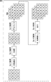
- FIG. 1 is a block diagram illustrating a configuration example of an embodiment of an image processing apparatus to which the present technology is applied.
- the image processing apparatus 11 in FIG. 1 receives input of image data captured by an imaging apparatus such as a camera (not shown), performs various processes, and then outputs the image data to a display apparatus such as a display (not shown). Is displayed.
- an imaging apparatus such as a camera (not shown)
- a display apparatus such as a display (not shown). Is displayed.
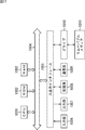
- the image processing apparatus 11 includes a CPU (Central Processing Unit) 31, a main memory 32, a bus 33, an IF (Interface) card 34, and GPU (Graphical Processing Units) cards 35-1 and 35-2. ing. Note that the GPU cards 35-1 and 35-2 are simply referred to as the GPU card 35 unless otherwise distinguished, and the other configurations are also referred to in the same manner.
- CPU Central Processing Unit
- main memory 32 main memory
- bus 33 a bus 33
- IF (Interface) card 34 IF (Interface) card 34
- GPU Graphic Processing Units
- a CPU (Central Processing Unit) 31 controls the overall operation of the image processing apparatus 11.
- the CPU 31 includes a DMA (Direct Memory Access) controller 51.
- DMA Direct Memory Access
- DMA controller 51 controls the transfer source, the transfer destination, and the transfer timing in the DMA transfer operation that is not directly managed by the CPU 31.
- the DMA controller 51 temporarily stores image data supplied as an input signal from a camera (not shown) via the IF card 34 and the bus 33 in the main memory 32.
- the DMA controller 51 also selects the main memory 32 according to the image data stored in the main memory 32, the processing capabilities of the processors 92-1 and 92-1 of the GPU cards 35-1 and 35-2, and the processing contents.
- the image data stored in is divided. Further, the DMA controller 51 assigns a timing for reading the divided image data for each range and a timing for storing the processed image data again. Further, the DMA controller 51 sequentially supplies the image data divided at the assigned timing to the GPU cards 35-1 and 35-2 and stores the processed image data in the main memory 32 sequentially. Then, the DMA controller 51 outputs the processed image data stored in the main memory 32 to the display (not shown) as an output signal via the bus 33 and the IF card 34 for display.
- the IF (Interface) card 34 includes a camera IF 71, a display IF 72, and a PCIe (Peripheral Component Interconnect Express) bridge 73.
- the camera IF 71 of the IF card 34 receives image data supplied as an input signal from a camera (not shown) under the management of the DMA controller 51, the image data is supplied to the main memory 32 via the PCIe bridge 73 and the bus 33.
- the display IF 72 of the IF card 34 outputs processed image data supplied from the main memory 32 via the bus 33 and the PCIe bridge 73 to the display (not shown) under the management of the DMA controller 51. Output as a signal.
- the GPU cards 35-1 and 35-2 include PCIe bridges 91-1 and 91-2, processors 92-1 and 92-2, and memories 93-1 and 93-2, respectively.
- the GPU card 35 temporarily stores image data supplied from the main memory 32 via the bus 33 and the PCIe bridge 91 under the management of the DMA controller 51 of the CPU 31 in the memory 93. Then, the processor 91 performs predetermined processing while sequentially reading the image data stored in the memory 93, buffers the processing result in the memory 93 as necessary, and also via the PCIe bridge 91 and the bus 33. Output to CPU 31.
- FIG. 1 an example in which there are two GPU cards 35 is shown, but two or more GPU cards may be used.
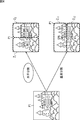
- image data (leftmost part), for example, consisting of a pixel array of a Bayer array, captured by a camera (not shown), is defect correction processing and RAWNR (Noise Reduction).
- RAWNR Noise Reduction
- an R (red) image, a G (green) image, and a B (blue) image (RGB image in the figure) are generated by demosaic processing. Further, the demosaiced R (red) image, G (green) image, and B (blue) image are subjected to an image quality enhancement process and then subjected to an enlargement process to form R ( A red) image, a G (green) image, and a B (blue) image are generated.
- the R (red) image, G (green) image, and B (blue) image generated in this way are output as output signals to a display unit such as a display (not shown) and displayed.
- image data supplied as an input signal by the DMA controller 51 is written and stored in the main memory 32 as indicated by “DMA INPUT # 0” in the drawing.
- the DMA controller 51 supplies the image data stored in the main memory 32 to the GPU card 35, and the processor 92 of the GPU card 35 Thus, process A is executed.
- the DMA controller 51 supplies the image data stored in the main memory 32 to the GPU card 35, and the processor 92 of the GPU card 35 Thus, the process B is executed, and the process result is returned to the main memory 32.
- the DMA controller 51 reads out and outputs the image data subjected to the processes A and B stored in the main memory 32. Is done.
- one GPU card 35 processes the entire frame and then tries to display it, it will not be displayed as an image until the processing result for one frame is generated, and the processing time will be enormous. And the latency becomes large, and there is a risk of delay in display.
- the frame is divided into several ranges in the vertical direction, and the processing is divided into small parts to reduce the latency.
- the lower part of FIG. 3 shows an example in which processing is performed when each of the frames is divided into three to form image data # 0 to # 2.
- image data # 0 supplied as an input signal by the DMA controller 51 is written to the main memory 32 as indicated by “DMAtINPUT ⁇ ⁇ # 0” in the figure from time t21 to t22. And memorized.
- the image data # 0 stored in the main memory 32 is supplied to the GPU card 35 by the DMA controller 51, as indicated by “processing A # 0” in the figure, and the GPU card 35 Processing A is executed by the processor 92.
- the DMA controller 51 supplies the image data stored in the main memory 32 to the GPU card 35, and the processor 92 of the GPU card 35 Thus, the process B is executed, and the process result is returned to the main memory 32.
- the DMA controller 51 From time t51 to t52, as indicated by “DMA OUTPUT # 0” in the figure, the DMA controller 51 outputs the image data # 0 subjected to the processes A and B stored in the main memory 32. .
- the DMA controller 51 supplies the image data # 1 stored in the main memory 32 to the GPU card 35, and the GPU card 35 Processing B is executed by the processor 92, and the processing result is returned to the main memory 32.
- the DMA controller 51 From time t53 to t54, as indicated by “DMA OUTPUT # 1” in the figure, the DMA controller 51 outputs the image data # 1 subjected to the processes A and B stored in the main memory 32. .
- the DMA controller 51 supplies the image data # 2 stored in the main memory 32 to the GPU card 35, and the GPU card 35 Processing B is executed by the processor 92, and the processing result is returned to the main memory 32.
- the DMA controller 51 outputs the image data # 2 subjected to the processes A and B stored in the main memory 32. .
- image data # 0 to # 2 are time-division processed, and “DMA INPUT”, “Process A”, “Process B”, and “DMA OUTPUT” are processed in parallel as necessary.
- the latency can be reduced as a whole.
- the display is also expeditious and the latency is reduced. Is possible.
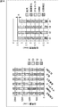
- the image is divided in the vertical direction to reduce the latency, and the image processing apparatus 11 in FIG. 1 is provided with a plurality of GPU cards 35. To do. That is, when the image data P1 shown in the left part of FIG. 4 is input, it is divided in the horizontal direction as shown in the upper right part of FIG. 4, and as described with reference to FIG. Time-sharing process.
- an area Z1 shown on the left side of the image data P1 is a processing range by “GPU # 0” corresponding to the GPU card 35-1, and is shown on the right side of the image data P1.
- the area Z2 to be processed is the processing range by “GPU # 1” corresponding to the GPU card 35-2.
- an example of the vertical division method in the conventional parallel processing is shown, and the processing by “GPU # 0” corresponding to the GPU card 35-1 indicated by the area Z11 in the upper stage.
- the lower part is the processing range by “GPU # 1” corresponding to the GPU card 35-2 indicated by the area Z12. That is, in the lower right part of FIG. 4, an example in which the GPU card 35 is divided into two in the vertical direction is shown.
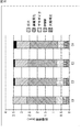
- the image processing apparatus 11 of FIG. 1 has a GPU card 35-1 when the areas Z1 and Z2 of the image P1 are each divided into ranges C1 to C4 in the vertical direction from the top. In the region Z1, time division processing is performed in the order of the ranges C1 to C4 (in order from the top to the bottom). Similarly, the image processing apparatus 11 in FIG. 1 controls the GPU card 35-2 to perform time division processing in the order of the ranges C1 to C4 in the region Z2.
- GPU cards 35 are processed in parallel in the horizontal direction, and further, image processing is performed by time-sharing processing in each GPU card 35 in the vertical direction. It is possible to increase the speed and to reduce the latency.
- the process executed on the image by the processor 92 of the GPU card 35 is generally a filter process.
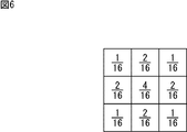
- a Gaussian filter as shown in FIG. 6 needs to be processed three times for each pixel.
- a Gaussian filter of 3 pixels ⁇ 3 pixels is used.
- the pixel of interest is 4/16
- the pixel of interest is 4 pixels above, below, left and right
- 2/16 is diagonally above and below the pixel of interest.
- 1/16 is a filter that sets each weighting factor as a weighting coefficient and calculates these sums as pixels.
- the first filtering process is performed on a range of 5 pixels ⁇ 5 pixels around the target pixel P to be processed.
- the pixels adjacent to the opposite side toward the target pixel by one pixel at the end portions are also required.
- one pixel adjacent to the opposite side to the target pixel in the diagonal direction is further required. That is, in order to perform the first filtering process on the range of 5 pixels ⁇ 5 pixels indicated by the square marked with “1”, a total of 7 pixels ⁇ 7 pixels centered on the pixel of interest P in the figure. Is required.
- the second filtering process is performed on a range of 3 pixels ⁇ 3 pixels centering on the target pixel P.
- the pixels adjacent to the opposite side toward the target pixel by one pixel at the ends are also required.
- one pixel adjacent to the opposite side to the target pixel is also required in the diagonal direction. That is, in the second filtering process, a total of 9 pixels in the range of 3 pixels ⁇ 3 pixels indicated by the squares with “2” in the figure are required.
- pixels in the range of 7 pixels ⁇ 7 pixels indicated by the hatched portion around the target pixel P are used.
- the filter process three times on the target pixel P it is possible to perform the filter process three times on the target pixel P. That is, when the target pixel is subjected to the filter process three times, the pixel in the region of 3 pixels ⁇ 3 pixels centered on the target pixel in the third process becomes the reference pixel.
- the reference pixels necessary for the second filter process are required for nine pixels centering on each of the nine pixels.
- a range of 5 pixels ⁇ 5 pixels is a reference pixel. Furthermore, each pixel of 5 pixels ⁇ 5 pixels is set as a reference pixel for each of the second reference pixels in the first process, and as a result, a range of 7 pixels ⁇ 7 pixels is required as a reference pixel.
- a pixel to be processed that is, a reference pixel other than the target pixel, which is required when processing the target pixel, or the number of reference pixels
- overhead an area in which the reference pixel exists
- the overhead pixels are generated for 48 pixels excluding the target pixel.
- a reference pixel is not an overhead pixel for a pixel that can be a pixel of interest separately.
- a pixel that is not an object to be processed but is required only as a reference pixel is referred to as overhead.
- the overhead width Dp is adopted as a method for expressing the amount of overhead generated for the target pixel.
- an overhead region OHZ1C2 occurs in the region Z1C2 specified by the range C2 in the second stage from the top in the region Z1 on the left side of the image P1.
- the overhead is estimated to be 8 times that of the overhead region OHZ1C2. Will do.
- overhead width Dp 2, 6, 8, 40, 8 pixels.
- an overhead of a total overhead width Dp 64 pixels occurs. That is, overhead pixels having the number of pixels excluding the target pixel are generated in the range of 129 pixels ⁇ 129 pixels. Further, for example, when dividing into two in the horizontal direction and dividing into four in the vertical direction, the overhead may increase by about 30% as compared to the case where no division processing is performed.
- the number of lines is wider than 1/4 of the total number of lines in the vertical direction for one frame including the number of lines of all reference pixels required in the above process.
- the ranges C2 and C3 are set so that the range is 1/4 of the total number of lines, and the remaining range is set for the last range C4.
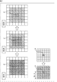
- the first filter processing (filter # 1), the second filter processing (filter # 2), and the nth filter processing (filter #n) are performed from the left, the ranges C1 to C4 are sequentially applied from the top. Shows the processing range to be performed on the entire image P1 when is sequentially processed.
- the processing result of the range C1 is buffered in the memory 93, and as a result of the processing of the range C2, the area where the necessary reference pixel exists is preliminarily set as indicated by the hatched portion at the lower right. Since the processing is completed in C1, it is only necessary to refer to this, so no overhead occurs. Further, since the range C1 is a range having a line number wider than 1/4 of the total number of lines, the position of the range C2 is 1 of the total number of lines at a position closer to the range C3 than the original range C2. / 4 range. As a result, the region where the reference pixel exists in the range C3 is buffered as the processing result of the range C2, so that it is not necessary to perform filtering again, thereby suppressing the occurrence of overhead.
- the position of the range C3 is set to 1 ⁇ 4 of the total number of lines closer to the range C4 than the original position of the range C3. Since the region where the reference pixel exists in C4 is buffered as the processing result of the range C3, it is not necessary to perform the filtering process again, thereby suppressing the occurrence of overhead.
- the processing area in the range C1 by the second filter processing (filter # 2) is 1 of the total number of lines including the reference pixels thereafter. This is a range wider than / 4, which is narrower than the number of lines of the first filter processing (filter # 1) indicated by the upward-sloping diagonal line at the upper left of FIG. After that, the ranges C2 and C3 are set so that the range is 1/4, and the remaining range is set for the last range C4.
- the area where the reference pixels exist becomes narrower by the smaller number of subsequent filters than the first filter process (filter # 1).
- the range is wider than 1/4 of the total number of lines, but is narrower than the range C1 of the first filter processing (filter # 1).
- the ranges C2 and C3 are also set so as to be shifted to positions close to 1 ⁇ 4 of the original total number of lines.
- the range C4 is set to be more than the range C1 in the first filter processing (filter # 1).
- the line width is increased by the reduced number of lines in the range C1.
- the filtering process is first performed in the preceding filtering process, the processing result is buffered, and used in the subsequent filtering process.
- the filtering process is first performed in the preceding filtering process, the processing result is buffered, and used in the subsequent filtering process.
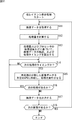
- step S11 the camera IF 71 of the IF card 34 accepts input of image data captured by a camera (not shown) and supplies it to the CPU 51 via the PCIe bridge 73 and the bus 33.
- the CPU 51 stores the image data input in response to this supply in the main memory 32.
- step S12 the DMA controller 51 divides the image in the horizontal direction according to the number of the GPU cards 35 based on the image data stored in the main memory 32, and further divides each divided area in the vertical direction.
- the amount of processing is calculated based on the number of ranges when dividing into the number of divisions for division processing, the number of filters related to the processing, and information on the area where the reference pixel exists.
- the processing amount is roughly divided into two types, that is, the processing amount related to the vertical processing and the processing amount related to the horizontal processing, and the DMA controller 51 calculates and adds them up.
- the processing result obtained by the first filter processing is processed by the second filter (filter # 2). Further, processing such as processing by the third filter processing (filter # 3) is repeated, and finally the n-th filter processing is performed, and the DMA transfer is performed and output (output DMA at the upper right part in the figure). .
- the number of lines PY (n ⁇ 1) of the (n ⁇ 1) th filter processing (filter # (n ⁇ 1)) is obtained by the following equation (1).
- PY (n ⁇ 1) PY (n) + BY (n ⁇ 1) ⁇ z ... (1)
- PY (n ⁇ 1) is the number of lines of the (n ⁇ 1) th filter process (filter # (n ⁇ 1)), and PY (n) is the line of the nth filter process (filter #n).
- the number BY (n ⁇ 1) indicates the number of lines indicating the size of the processing unit block in the (n ⁇ 1) th filter processing (filter # (n ⁇ 1)).
- Z is a value such that BY (n ⁇ 1) ⁇ A is larger than the number of reference pixels and A is minimum.
- the (n ⁇ 1) th filter processing (filter # (n) is performed with respect to the number of lines (number of processing lines) output by the n th filter processing (filter #n).
- the number of lines constituting the reference pixel in -1) is a range painted in a grid pattern.
- the number of processing lines in the n-th filter processing is equivalent to four blocks of processing unit blocks each having a predetermined number of lines indicated by a downward slanting portion at the lower right in FIG.
- the reference pixels in the (n ⁇ 1) th filter processing as shown as a grid-like range in the lower right part of FIG. There is no range for several lines.
- each filter processing can be performed only for each processing unit block having a predetermined number of lines. Therefore, in the case of the lower right part of FIG. 12, the part having the number of lines less than one block is regarded as one block. Thereby, in the lower right part of FIG. 12, z shown by Formula (1) will be calculated
- the number of processing lines for the (n-1) th filter processing (filter # (n-1)) is substantially obtained as the number of lines for 7 blocks. .
- filter # 1 the number of processing unit blocks up to the first filter processing (filter # 1) is calculated, the processing amount corresponding to the processing unit block number is sequentially calculated, and the total is calculated as the vertical processing amount.
- the number of lines required in each filter processing is the number of lines including reference pixels required in the subsequent stage of each filter so as to reduce overhead as described with reference to FIG. Is set.
- ⁇ Horizontal processing amount> The amount of processing in the horizontal direction is also stored in the main memory 32, and the first filter processing (filter # 1) to the n-th filter processing (filter #n) with reference to the output buffer size output by DMA.
- the number of reference pixels and the processing unit block in each of the filter processes up to are sequentially obtained in the reverse order of the processing order.
- the processing result obtained by the first filter process is processed by the second filter process (filter # 2). Further, the process such as the third filter process (filter # 3) is repeated, and finally the n-th filter process (filter #n) is performed, and the DMA transfer is performed (output DMA in the figure). ).
- the calculation of the amount of processing in the horizontal direction is obtained from the number of reference pixels and the processing unit block in each filter processing sequentially in the reverse direction from the width defined by the multiple of the processing unit block in the horizontal direction of the output DMA. Go.
- the processing for reducing overhead in the vertical processing is not performed, and the width in the horizontal direction in each filter processing is equal to the number of processing unit blocks corresponding to the number of reference pixels in each filter processing. Is a processing amount corresponding to the horizontal width simply added.
- the horizontal width Xk required for calculating the processing amount in the k-th filter processing #k is expressed by the following equation (2).
- Xk is a width required for calculating the processing amount in the kth filter processing #k
- w is a horizontal direction set by a multiple of the processing unit block in the nth filter processing #n. This is the width
- zx is the width of the processing unit block.
- Zk is the sum of the reference pixel numbers in the previous filter process (r1 + r2 +... + R (k ⁇ 1) + rk), where ri is the reference pixel number in the i-th filter process (filter #i). And zk ⁇ xk is a minimum value.
- the reference pixel in the fifth filter process (filter # 5) with respect to the width of the sixth filter process (filter # 6) corresponding to the nth filter process (filter #n) as the output buffer size Assume that the number is two.
- filter # 4 if the number of reference pixels is 1, in this case, in the fifth filter process (filter # 5), 2 which is the number of reference pixels is added to be 3 as indicated by the diagonally shaded area in the lower right.
- the processing amount corresponding to the combined result of the widths that are multiples of the processing unit blocks to be processed in the horizontal filters is sequentially obtained.
- the DMA controller 51 calculates the vertical processing amount and the horizontal processing amount described above according to the number of horizontal divisions and the number of vertical divisions of the image, and adds both of them to be necessary for processing. Calculate the amount of processing to be done.
- step 13 the DMA controller 51 calculates processing times for various filter processes according to the processing capacity of the processors 92 mounted on the GPU card 35 and the processing amount obtained by the above calculation. Further, various timings such as image data reading or transfer timing are calculated from the obtained processing time. With this process, a timing chart indicating which image data is transferred to which GPU card 35 at which timing in the subsequent processes is constructed.
- step S14 the DMA controller 51 starts processing from a predetermined timing based on this timing chart, determines whether or not the current processing timing is now, and until the next processing timing is reached. Repeat the same process.
- step S14 for example, if it is determined that it is time to start the next process, the process proceeds to step S15.
- step S15 the DMA controller 51 reads out the image data set as the next processing from the main memory 32 based on the timing chart, and transfers it to the GPU card 35 set as the transfer destination.
- the processor 92 of the card 35 is caused to execute processing.
- the DMA controller 51 receives this and stores it in the main memory 32.
- step S16 the DMA controller 51 refers to the timing chart to determine whether or not the next process exists. For example, if there is a next process, the process returns to step S14, and the subsequent processes are performed. Repeated.
- steps S14 to S16 are repeated until it is determined in step S16 that there is no next process. Then, when the processes of steps S14 to S16 are repeated and all the processes set in the timing chart are completed, it is considered that there is no next process in step S16, and the process proceeds to step S17.
- step S ⁇ b> 17 the DMA controller 51 displays the image data stored in the main memory 32 and subjected to processing such as high image quality from the display IF 72 via the bus 33 and the PCIe bridge 73 of the IF card 34. To output.
- step S18 the DMA controller 51 determines whether or not the next image has been supplied. If the next image exists, the process returns to step S11, and the subsequent processing is repeated.
- step S18 If it is determined in step S18 that the next image is not supplied, the process ends.
- the images are divided in the horizontal direction by the processors 92 of the plurality of GPU cards 35 and are shared by the processors 92 for processing.
- each processor 92 is divided into a predetermined number of ranges in the vertical direction, and the divided ranges are subjected to time division processing. In this time division processing, the range in which the reference pixel exists in the subsequent filter processing is executed in the previous filter processing and is buffered in the memory 93.
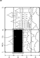
- the left part of FIG. 14 shows the reference pixels in the subsequent filtering process in the preceding filtering process so as to reduce overhead in various processes such as defect correction, RAWNR, demosaicing, high image quality, enlargement, and output DMA.
- An example of the number of lines set in the ranges C1 to C4 when buffering is performed is shown.
- the number of lines in the ranges C1 to C4 in the defect correction process is 604, 540, 540, and 476 lines
- the number of lines in the ranges C1 to C4 in the RAWNR process is 596,540, 540 and 484 lines
- the number of lines in the ranges C1 to C4 in the demosaic process is 588, 540, 540, and 492 lines.
- the number of lines in the ranges C1 to C4 in the image quality improvement processing is 548, 540, 540, and 532 lines
- the number of lines in the expansion processing ranges C1 to C4 is 540, 540, 540, and 540 lines. It is shown that the number of lines in the output DMA processing range C1 to C4 is 540, 540, 540, and 540 lines.
- the processing time in the ranges C1 to C4 is as shown in the right part of FIG. 14, and the maximum difference ⁇ in the total processing time in the ranges C1 to C4 is, for example, the processing time in the ranges C1 and C4. This is a difference, and is about 5% of the processing time in the range C1. This is caused by the change in the number of processing lines for the purpose of reducing overhead in the filtering process in the vertical direction, and is caused by changing various processing times.
- the total processing time and the breakdown of each processing time in the ranges C1 to C4 from the left are shown.
- the number of lines to be finally output may be adjusted to smooth the processing time.
- the processing time non-uniformity is eliminated such that the number of lines in the output DMA processing is 520 lines for the range C1 and 560 lines for the range C4. To be non-uniform.
- the processing time difference ⁇ in the ranges C1 and C4 is almost eliminated, and the processing time can be smoothed and made uniform as a whole. It becomes.
- the upper left part and upper right part of FIG. 15 are the same as the left part and right part of FIG. 14, respectively.
- processing that does not need to adjust the processing speed in real time may be shared.
- FIG. It may be assigned to detection processing or the like in the time zone indicated by the uppermost black range in C2 to C4 so that the processing time becomes uniform as a whole.
- the image is divided in the horizontal direction, assigned to a plurality of processors, the horizontally divided areas are time-divided in the vertical direction, and the ranges divided in the vertical direction are The range including the reference pixels required for the subsequent processing is set in the range. Then, in the processing of the top range, the buffer processing is performed after performing the filtering processing including the processing of the reference pixel in advance, and in the subsequent filtering processing, the processing is executed with reference to the buffered one. did.
- the display processing of the captured image can be reduced in latency, and the captured image can be displayed at high speed at a timing closer to the actual time when the captured image is captured.
- the image processing apparatus 11 in FIG. 1 uses, for example, an endoscope that is used for endoscopic surgery as an imaging device that images a patient's surgical part, a microscope that is used for neurosurgery, and the like.
- the present invention can be applied to an image processing apparatus that processes an image obtained by imaging an operation part, and further to a surgical system including an endoscope or a microscope as an imaging apparatus.
- the processor 92 in the GPU card 35 it is possible to reduce consideration of a time lag or the like in displaying an image, so that it is possible to improve programmability.
- displaying an image received via a broadcast wave or the like it is possible to reduce the latency, so that it is possible to display the image while suppressing the time lag.
- the DMA controller 51 calculates the processing amount in advance according to the number of reference pixels corresponding to the filter used for processing and the processing unit block, and then reads out the image data and writes the image data. Since the processing is executed after optimizing, it is possible to reduce the latency in an optimum state regardless of the processing content.
- the above-described series of processing can be executed by hardware, but can also be executed by software.
- a program constituting the software may execute various functions by installing a computer incorporated in dedicated hardware or various programs. For example, it is installed from a recording medium in a general-purpose personal computer or the like.
- FIG. 17 shows a configuration example of a general-purpose personal computer.
- This personal computer incorporates a CPU (Central Processing Unit) 1001.
- An input / output interface 1005 is connected to the CPU 1001 via a bus 1004.
- a ROM (Read Only Memory) 1002 and a RAM (Random Access Memory) 1003 are connected to the bus 1004.
- the input / output interface 1005 includes an input unit 1006 including an input device such as a keyboard and a mouse for a user to input an operation command, an output unit 1007 for outputting a processing operation screen and an image of the processing result to a display device, programs, and various types.
- a storage unit 1008 including a hard disk drive for storing data, a LAN (Local Area Network) adapter, and the like are connected to a communication unit 1009 that executes communication processing via a network represented by the Internet.
- magnetic disks including flexible disks
- optical disks including CD-ROM (Compact Disc-Read Only Memory), DVD (Digital Versatile Disc)), magneto-optical disks (including MD (Mini Disc)), or semiconductors
- a drive 1010 for reading / writing data from / to a removable medium 1011 such as a memory is connected.
- the CPU 1001 is read from a program stored in the ROM 1002 or a removable medium 1011 such as a magnetic disk, an optical disk, a magneto-optical disk, or a semiconductor memory, installed in the storage unit 1008, and loaded from the storage unit 1008 to the RAM 1003. Various processes are executed according to the program.
- the RAM 1003 also appropriately stores data necessary for the CPU 1001 to execute various processes.
- the CPU 1001 loads the program stored in the storage unit 1008 to the RAM 1003 via the input / output interface 1005 and the bus 1004 and executes the program, for example. Is performed.
- the program executed by the computer (CPU 1001) can be provided by being recorded on the removable medium 1011 as a package medium, for example.
- the program can be provided via a wired or wireless transmission medium such as a local area network, the Internet, or digital satellite broadcasting.
- the program can be installed in the storage unit 1008 via the input / output interface 1005 by attaching the removable medium 1011 to the drive 1010. Further, the program can be received by the communication unit 1009 via a wired or wireless transmission medium and installed in the storage unit 1008. In addition, the program can be installed in advance in the ROM 1002 or the storage unit 1008.
- the program executed by the computer may be a program that is processed in time series in the order described in this specification, or in parallel or at a necessary timing such as when a call is made. It may be a program for processing.
- the system means a set of a plurality of components (devices, modules (parts), etc.), and it does not matter whether all the components are in the same housing. Accordingly, a plurality of devices housed in separate housings and connected via a network and a single device housing a plurality of modules in one housing are all systems. .
- the present technology can take a cloud computing configuration in which one function is shared by a plurality of devices via a network and is jointly processed.
- each step described in the above flowchart can be executed by one device or can be shared by a plurality of devices.
- the plurality of processes included in the one step can be executed by being shared by a plurality of apparatuses in addition to being executed by one apparatus.
- this technique can also take the following structures. (1) including a plurality of arithmetic processing units that perform processing in a time-sharing manner for each range in which an image obtained by imaging a patient's surgical part is vertically divided; The image processing device, wherein the arithmetic processing unit performs processing by time-dividing the image divided in the horizontal direction by the number of the arithmetic processing units in the vertical direction. (2) The plurality of arithmetic processing units are configured by a plurality of GPUs (Graphical Processing Units), The image processing device according to (1), wherein the arithmetic processing unit performs processing on the image divided in the horizontal direction by the number of the GPUs.
- GPUs Graphic Processing Units
- the image processing apparatus according to (1) or (2), wherein the process performed on the image is a process of applying an n-stage filter.
- the n stages of filters perform processing in a time-division manner in order from a range obtained by dividing the image in the vertical direction from the uppermost stage in the vertical direction downward.
- Image processing device (5) Based on the amount of processing performed on the image calculated based on the number of horizontal divisions and the number of vertical divisions of the image, and the processing speed of the arithmetic processing unit, the arithmetic processing unit.
- the image processing apparatus according to any one of (1) to (4), further including a timing control unit that controls timing of the calculation.
- the processing range in the first period includes reference pixels required for processing in the second period after the first period.
- the image processing device according to any one of (1) to (5).
- the arithmetic processing unit includes a memory for buffering a processing result, In the process of the second period, an arithmetic process is executed using a process result corresponding to the reference pixel from the process result of the first period buffered in the memory. Processing equipment.
- the arithmetic processing unit includes a memory for buffering a processing result, Of the range obtained by dividing the image in the vertical direction, the uppermost processing range in the vertical direction by the filter at each stage is required for the processing of the filter in the processing range of the second stage or less in the vertical direction. A range that includes the number of reference pixel lines, When the arithmetic processing unit executes arithmetic processing for processing by the filter, the processing using the reference pixel is performed on the reference pixel from the processing result of the filtering processing up to the previous stage buffered in the memory.
- the image processing apparatus according to (3) wherein arithmetic processing is executed using a corresponding processing result.
- the image processing device according to any one of (1) to (8), wherein the arithmetic processing unit performs at least an enlargement process on an image obtained by imaging the surgical site of the patient.
- the image processing device according to any one of (1) to (9), wherein the image obtained by imaging the surgical site of the patient is an image taken by an endoscope.
- the image processing device according to any one of (1) to (9), wherein the image obtained by imaging the surgical site of the patient is an image taken by a microscope. (12) In an image processing method of an image processing apparatus including a plurality of arithmetic processing units that perform time-division processing on an image obtained by imaging a patient's surgical part for each range divided in the vertical direction.
- the operation system includes: an image processing device that performs processing by time-dividing the image divided in the horizontal direction in the vertical direction by the number of the arithmetic processing units.
Abstract
Description
図1は、本技術を適用した画像処理装置の一実施の形態の構成例を示すブロック図である。 <Configuration example of image processing apparatus>
FIG. 1 is a block diagram illustrating a configuration example of an embodiment of an image processing apparatus to which the present technology is applied.
次に、図2を参照して、図1の画像処理装置11による画像処理について説明する。 <About image processing>
Next, image processing by the
上述したような画像処理を、従来のようにフレーム単位で実行した場合、処理は、図3の上段で示されるようなタイムチャートとなる。尚、ここでは、画像に対してなされる処理は、処理A,Bの2種類のみであるものとする。また、図3の上段においては、GPUカード35と同一のGPUカードが1枚存在する構成であるものとする。 <Low latency>
When the image processing as described above is executed in units of frames as in the prior art, the processing becomes a time chart as shown in the upper part of FIG. Here, it is assumed that only two types of processes A and B are performed on the image. In the upper part of FIG. 3, it is assumed that there is one GPU card identical to the GPU card 35.
上述したように、垂直方向に画像を分割して低レイテンシ化を実現させると共に、さらに、図1の画像処理装置11は、複数のGPUカード35が設けられているので、同様の処理を並列処理する。すなわち、図4の左部で示される画像データP1が入力される場合、図4の右上部で示されるように、水平方向に分割し、それぞれ図3を参照して説明したように、垂直方向に時分割処理する。 <Horizontal division>
As described above, the image is divided in the vertical direction to reduce the latency, and the
また、図1の画像処理装置11は、図5で示されるように、画像P1の領域Z1,Z2がそれぞれ、上から垂直方向に範囲C1乃至C4に4分割されるとき、GPUカード35-1を制御して、領域Z1においては範囲C1乃至C4の順序で(上から順に下に向かう順序で)時分割処理する。同様に、図1の画像処理装置11は、GPUカード35-2を制御して、領域Z2において範囲C1乃至C4の順序で時分割処理する。 <Vertical division>
Further, as shown in FIG. 5, the
GPUカード35のプロセッサ92により画像に対して実行される処理は、一般的に、フィルタ処理である。例えば、図6で示されるようなガウシアンフィルタを、各画素に対して3回処理する必要がある場合を考える。尚、図6においては、3画素×3画素のガウシアンフィルタであり、注目画素に4/16が、注目画素の上下左右の4画素に2/16が、注目画素の左右斜め上下の4画素に1/16がそれぞれ重み係数として設定され、これらの関和を画素として演算するフィルタである。 <Overhead>
The process executed on the image by the processor 92 of the GPU card 35 is generally a filter process. For example, consider a case where a Gaussian filter as shown in FIG. 6 needs to be processed three times for each pixel. In FIG. 6, a Gaussian filter of 3 pixels × 3 pixels is used. The pixel of interest is 4/16, the pixel of interest is 4 pixels above, below, left and right, and 2/16 is diagonally above and below the pixel of interest. 1/16 is a filter that sets each weighting factor as a weighting coefficient and calculates these sums as pixels.
以上のようにオーバヘッドが増えると演算処理量が膨大なものとなり、処理時間が大きくなることで、リアルタイムを達成するためにより演算性能の高いプロセッサを必要としてしまう。そこで、図1の画像処理装置11においては、次のような演算によりオーバヘッドを削減している。すなわち、GPUカード35-1,35-2のそれぞれに画像P1のうちの処理領域として領域Z1,Z2が割り付けられている場合、メモリ93-1,93-2に前段のフィルタ処理結果をバッファリングさせて、後段のフィルタ処理で流用できるようにする。 <Overhead reduction method>
As described above, when the overhead increases, the amount of calculation processing becomes enormous, and the processing time increases, so that a processor with higher calculation performance is required to achieve real time. Therefore, in the
次に、図11のフローチャートを参照して、図1の画像処理装置11による低レイテンシ表示処理について説明する。 <Low latency display processing>
Next, low latency display processing by the
すなわち、垂直方向については、最終的にメインメモリ32に格納された後に、DMA出力される出力バッファサイズを基準として、第1フィルタ処理#1(フィルタ#1)による処理から第nフィルタ処理(フィルタ#n)による処理までの各フィルタ処理における参照ピクセル数と処理単位ブロックとにより順次、処理順序と逆の順序で求められる。 <Vertical processing amount>
That is, with respect to the vertical direction, after being finally stored in the
・・・(1) PY (n−1) = PY (n) + BY (n−1) × z
... (1)
水平方向の処理量についても、最終的にメインメモリ32に格納された後に、DMA出力される出力バッファサイズを基準として、第1フィルタ処理(フィルタ#1)から第nフィルタ処理(フィルタ#n)までの各フィルタ処理における参照ピクセル数と処理単位ブロックとにより順次、処理順序と逆の順序で求められる。 <Horizontal processing amount>
The amount of processing in the horizontal direction is also stored in the
・・・(2) Xk = w + zk × xk
... (2)
以上の処理により、垂直方向のフィルタ処理におけるオーバヘッド削減とのトレードオフにより、各種の処理時間が変化することがある。 <Uniform processing time>
With the above processing, various processing times may change due to a trade-off with overhead reduction in vertical filter processing.
(1) 患者の術部が撮像された画像を垂直方向に分割された範囲毎に時分割で処理を施す複数の演算処理部を含み、
前記演算処理部は、前記演算処理部の数で、水平方向に分割された前記画像を、前記垂直方向に時分割して処理を施す
画像処理装置。
(2) 前記複数の演算処理部は、複数のGPU(Graphical Processing Unit)により構成され、
前記演算処理部は、前記GPUの数で水平方向に分割された前記画像に処理を施す
(1)に記載の画像処理装置。
(3) 前記画像に施す処理は、n段のフィルタを掛ける処理である
(1)または(2)に記載の画像処理装置。
(4) 前記n段の前記フィルタは、それぞれ前記画像を垂直方向に分割した範囲を、前記垂直方向の最上段の範囲から下方向に向かって順次時分割で処理を施す
(3)に記載の画像処理装置。
(5) 前記画像の前記水平方向の分割数、および前記垂直方向の分割数に基づいて算出される前記画像に施す処理量と、前記演算処理部の処理速度とに基づいて、前記演算処理部の演算のタイミングを制御するタイミング制御部をさらに含む
(1)乃至(4)のいずれかに記載の画像処理装置。
(6) 前記画像を前記垂直方向に時分割した範囲のうち、第1の期間の処理範囲には、前記第1の期間より後の第2の期間の処理に必要とされる参照ピクセルが含まれる
(1)乃至(5)のいずれかに記載の画像処理装置。
(7) 前記演算処理部は、処理結果をバッファリングするメモリを含み、
前記第2の期間の処理では、前記メモリにバッファリングされた前記第1の期間の処理結果から、前記参照ピクセルに対応する処理結果を利用して演算処理を実行する
(6)に記載の画像処理装置。
(8) 前記演算処理部は、処理結果をバッファリングするメモリを含み、
前記画像を垂直方向に分割した範囲のうち、各段の前記フィルタによる前記垂直方向の最上段の処理範囲は、前記垂直方向の2段目以下の処理範囲における前記フィルタの処理に必要とされる参照ピクセルのライン数を含む範囲とし、
前記演算処理部は、前記フィルタによる処理のための演算処理を実行するにあたり、前記参照ピクセルを利用する処理は、前記メモリにバッファリングされた前段までのフィルタ処理の処理結果から、前記参照ピクセルに対応する処理結果を利用して演算処理を実行する
(3)に記載の画像処理装置。
(9) 前記演算処理部は、前記患者の術部が撮像された画像に対して、少なくとも拡大処理を施す
(1)乃至(8)のいずれかに記載の画像処理装置。
(10) 前記患者の術部が撮像された画像は、内視鏡により撮像された画像である
(1)乃至(9)のいずれかに記載の画像処理装置。
(11) 前記患者の術部が撮像された画像は、顕微鏡により撮像された画像である
(1)乃至(9)のいずれかに記載の画像処理装置。
(12) 患者の術部が撮像された画像を垂直方向に分割された範囲毎に時分割で処理を施す複数の演算処理部を含む画像処理装置の画像処理方法において、
前記演算処理部は、前記演算処理部の数で、水平方向に分割された前記画像を、前記垂直方向に時分割して処理を施す
画像処理方法。
(13) 前記画像は、内視鏡により撮像された画像である
(12)に記載の画像処理方法。
(14) 前記画像は、顕微鏡により撮像された画像である
(12)に記載の画像処理方法。
(15) 患者の術部を撮像する撮像装置と、
前記撮像装置により撮像された画像を垂直方向に分割された範囲毎に時分割で処理を施す複数の演算処理部を含み、
前記演算処理部は、前記演算処理部の数で、水平方向に分割された前記画像を、前記垂直方向に時分割して処理を施す
画像処理装置と
を有する手術システム。 In addition, this technique can also take the following structures.
(1) including a plurality of arithmetic processing units that perform processing in a time-sharing manner for each range in which an image obtained by imaging a patient's surgical part is vertically divided;
The image processing device, wherein the arithmetic processing unit performs processing by time-dividing the image divided in the horizontal direction by the number of the arithmetic processing units in the vertical direction.
(2) The plurality of arithmetic processing units are configured by a plurality of GPUs (Graphical Processing Units),
The image processing device according to (1), wherein the arithmetic processing unit performs processing on the image divided in the horizontal direction by the number of the GPUs.
(3) The image processing apparatus according to (1) or (2), wherein the process performed on the image is a process of applying an n-stage filter.
(4) The n stages of filters perform processing in a time-division manner in order from a range obtained by dividing the image in the vertical direction from the uppermost stage in the vertical direction downward. Image processing device.
(5) Based on the amount of processing performed on the image calculated based on the number of horizontal divisions and the number of vertical divisions of the image, and the processing speed of the arithmetic processing unit, the arithmetic processing unit The image processing apparatus according to any one of (1) to (4), further including a timing control unit that controls timing of the calculation.
(6) Of the range in which the image is time-divided in the vertical direction, the processing range in the first period includes reference pixels required for processing in the second period after the first period. The image processing device according to any one of (1) to (5).
(7) The arithmetic processing unit includes a memory for buffering a processing result,
In the process of the second period, an arithmetic process is executed using a process result corresponding to the reference pixel from the process result of the first period buffered in the memory. Processing equipment.
(8) The arithmetic processing unit includes a memory for buffering a processing result,
Of the range obtained by dividing the image in the vertical direction, the uppermost processing range in the vertical direction by the filter at each stage is required for the processing of the filter in the processing range of the second stage or less in the vertical direction. A range that includes the number of reference pixel lines,
When the arithmetic processing unit executes arithmetic processing for processing by the filter, the processing using the reference pixel is performed on the reference pixel from the processing result of the filtering processing up to the previous stage buffered in the memory. The image processing apparatus according to (3), wherein arithmetic processing is executed using a corresponding processing result.
(9) The image processing device according to any one of (1) to (8), wherein the arithmetic processing unit performs at least an enlargement process on an image obtained by imaging the surgical site of the patient.
(10) The image processing device according to any one of (1) to (9), wherein the image obtained by imaging the surgical site of the patient is an image taken by an endoscope.
(11) The image processing device according to any one of (1) to (9), wherein the image obtained by imaging the surgical site of the patient is an image taken by a microscope.
(12) In an image processing method of an image processing apparatus including a plurality of arithmetic processing units that perform time-division processing on an image obtained by imaging a patient's surgical part for each range divided in the vertical direction.
An image processing method in which the arithmetic processing unit performs processing by time-dividing the image divided in the horizontal direction in the vertical direction by the number of the arithmetic processing units.
(13) The image processing method according to (12), wherein the image is an image captured by an endoscope.
(14) The image processing method according to (12), wherein the image is an image captured by a microscope.
(15) an imaging device for imaging the surgical site of a patient;
A plurality of arithmetic processing units that perform processing in a time-sharing manner for each range divided in the vertical direction of the image captured by the imaging device;
The operation system includes: an image processing device that performs processing by time-dividing the image divided in the horizontal direction in the vertical direction by the number of the arithmetic processing units.
Claims (15)
- 患者の術部が撮像された画像を垂直方向に分割された範囲毎に時分割で処理を施す複数の演算処理部を含み、
前記演算処理部は、前記演算処理部の数で、水平方向に分割された前記画像を、前記垂直方向に時分割して処理を施す
画像処理装置。 A plurality of arithmetic processing units that perform processing in a time-sharing manner for each range divided vertically in an image obtained by imaging a patient's surgical part,
The image processing device, wherein the arithmetic processing unit performs processing by time-dividing the image divided in the horizontal direction by the number of the arithmetic processing units in the vertical direction. - 前記複数の演算処理部は、複数のGPU(Graphical Processing Unit)により構成され、
前記演算処理部は、前記GPUの数で水平方向に分割された前記画像に処理を施す
請求項1に記載の画像処理装置。 The plurality of arithmetic processing units are configured by a plurality of GPUs (Graphical Processing Units),
The image processing apparatus according to claim 1, wherein the arithmetic processing unit performs processing on the image divided in the horizontal direction by the number of GPUs. - 前記画像に施す処理は、n段のフィルタを掛ける処理である
請求項1に記載の画像処理装置。 The image processing apparatus according to claim 1, wherein the process applied to the image is a process of applying an n-stage filter. - 前記n段の前記フィルタは、それぞれ前記画像を垂直方向に分割した範囲を、前記垂直方向の最上段の範囲から下方向に向かって順次時分割で処理を施す
請求項3に記載の画像処理装置。 The image processing apparatus according to claim 3, wherein each of the n stages of filters sequentially processes a range obtained by dividing the image in the vertical direction in a time-division manner from the uppermost range in the vertical direction downward. . - 前記画像の前記水平方向の分割数、および前記垂直方向の分割数に基づいて算出される前記画像に施す処理量と、前記演算処理部の処理速度とに基づいて、前記演算処理部の演算のタイミングを制御するタイミング制御部をさらに含む
請求項1に記載の画像処理装置。 Based on the amount of processing performed on the image calculated based on the number of divisions in the horizontal direction and the number of divisions in the vertical direction of the image, and the processing speed of the arithmetic processing unit, The image processing apparatus according to claim 1, further comprising a timing control unit that controls timing. - 前記画像を前記垂直方向に時分割した範囲のうち、第1の期間の処理範囲には、前記第1の期間より後の第2の期間の処理に必要とされる参照ピクセルが含まれる
請求項1に記載の画像処理装置。 The reference pixel that is required for processing in a second period after the first period is included in the processing range in the first period among the range in which the image is time-divided in the vertical direction. The image processing apparatus according to 1. - 前記演算処理部は、処理結果をバッファリングするメモリを含み、
前記第2の期間の処理では、前記メモリにバッファリングされた前記第1の期間の処理結果から、前記参照ピクセルに対応する処理結果を利用して演算処理を実行する
請求項6に記載の画像処理装置。 The arithmetic processing unit includes a memory for buffering a processing result,
7. The image according to claim 6, wherein in the processing of the second period, an arithmetic process is executed using a processing result corresponding to the reference pixel from a processing result of the first period buffered in the memory. Processing equipment. - 前記演算処理部は、処理結果をバッファリングするメモリを含み、
前記画像を垂直方向に分割した範囲のうち、各段の前記フィルタによる前記垂直方向の最上段の処理範囲は、前記垂直方向の2段目以下の処理範囲における前記フィルタの処理に必要とされる参照ピクセルのライン数を含む範囲とし、
前記演算処理部は、前記フィルタによる処理のための演算処理を実行するにあたり、前記参照ピクセルを利用する処理は、前記メモリにバッファリングされた前段までのフィルタ処理の処理結果から、前記参照ピクセルに対応する処理結果を利用して演算処理を実行する
請求項3に記載の画像処理装置。 The arithmetic processing unit includes a memory for buffering a processing result,
Of the range obtained by dividing the image in the vertical direction, the uppermost processing range in the vertical direction by the filter at each stage is required for the processing of the filter in the processing range of the second stage or less in the vertical direction. A range that includes the number of reference pixel lines,
When the arithmetic processing unit performs arithmetic processing for the processing by the filter, the processing using the reference pixel is performed on the reference pixel from the processing result of the filtering processing up to the previous stage buffered in the memory. The image processing apparatus according to claim 3, wherein arithmetic processing is executed using a corresponding processing result. - 前記演算処理部は、前記患者の術部が撮像された画像に対して、少なくとも拡大処理を施す
請求項1に記載の画像処理装置。 The image processing apparatus according to claim 1, wherein the arithmetic processing unit performs at least enlargement processing on an image obtained by imaging the surgical site of the patient. - 前記患者の術部が撮像された画像は、内視鏡により撮像された画像である
請求項1に記載の画像処理装置。 The image processing apparatus according to claim 1, wherein the image obtained by imaging the surgical site of the patient is an image obtained by an endoscope. - 前記患者の術部が撮像された画像は、顕微鏡により撮像された画像である
請求項1に記載の画像処理装置。 The image processing apparatus according to claim 1, wherein the image obtained by imaging the surgical site of the patient is an image taken by a microscope. - 患者の術部が撮像された画像を垂直方向に分割された範囲毎に時分割で処理を施す複数の演算処理部を含む画像処理装置の画像処理方法において、
前記演算処理部は、前記演算処理部の数で、水平方向に分割された前記画像を、前記垂直方向に時分割して処理を施す
画像処理方法。 In an image processing method of an image processing apparatus including a plurality of arithmetic processing units that perform time-division processing for each range divided in the vertical direction from an image obtained by imaging a patient's surgery unit,
An image processing method in which the arithmetic processing unit performs processing by time-dividing the image divided in the horizontal direction in the vertical direction by the number of the arithmetic processing units. - 前記画像は、内視鏡により撮像された画像である
請求項12に記載の画像処理方法。 The image processing method according to claim 12, wherein the image is an image captured by an endoscope. - 前記画像は、顕微鏡により撮像された画像である
請求項12に記載の画像処理方法。 The image processing method according to claim 12, wherein the image is an image captured by a microscope. - 患者の術部を撮像する撮像装置と、
前記撮像装置により撮像された画像を垂直方向に分割された範囲毎に時分割で処理を施す複数の演算処理部を含み、
前記演算処理部は、前記演算処理部の数で、水平方向に分割された前記画像を、前記垂直方向に時分割して処理を施す
画像処理装置と
を有する手術システム。 An imaging device for imaging a patient's surgical site;
A plurality of arithmetic processing units that perform processing in a time-sharing manner for each range divided in the vertical direction of the image captured by the imaging device;
The operation system includes: an image processing device that performs processing by time-dividing the image divided in the horizontal direction in the vertical direction by the number of the arithmetic processing units.
Priority Applications (5)
| Application Number | Priority Date | Filing Date | Title |
|---|---|---|---|
| US15/304,559 US10440241B2 (en) | 2014-04-24 | 2015-04-13 | Image processing apparatus, image processing method, and surgical system |
| EP15782241.2A EP3136719A4 (en) | 2014-04-24 | 2015-04-13 | Image processing apparatus and method and surgical operation system |
| JP2016514864A JP6737176B2 (en) | 2014-04-24 | 2015-04-13 | Image processing apparatus and method, and surgical system |
| CN201580020303.2A CN106233719B (en) | 2014-04-24 | 2015-04-13 | Image processing apparatus and method, and surgical system |
| US16/555,236 US11245816B2 (en) | 2014-04-24 | 2019-08-29 | Image processing apparatus, image processing method, and surgical system |
Applications Claiming Priority (2)
| Application Number | Priority Date | Filing Date | Title |
|---|---|---|---|
| JP2014090566 | 2014-04-24 | ||
| JP2014-090566 | 2014-04-24 |
Related Child Applications (2)
| Application Number | Title | Priority Date | Filing Date |
|---|---|---|---|
| US15/304,559 A-371-Of-International US10440241B2 (en) | 2014-04-24 | 2015-04-13 | Image processing apparatus, image processing method, and surgical system |
| US16/555,236 Continuation US11245816B2 (en) | 2014-04-24 | 2019-08-29 | Image processing apparatus, image processing method, and surgical system |
Publications (1)
| Publication Number | Publication Date |
|---|---|
| WO2015163171A1 true WO2015163171A1 (en) | 2015-10-29 |
Family
ID=54332338
Family Applications (1)
| Application Number | Title | Priority Date | Filing Date |
|---|---|---|---|
| PCT/JP2015/061311 WO2015163171A1 (en) | 2014-04-24 | 2015-04-13 | Image processing apparatus and method and surgical operation system |
Country Status (5)
| Country | Link |
|---|---|
| US (2) | US10440241B2 (en) |
| EP (1) | EP3136719A4 (en) |
| JP (1) | JP6737176B2 (en) |
| CN (1) | CN106233719B (en) |
| WO (1) | WO2015163171A1 (en) |
Cited By (6)
| Publication number | Priority date | Publication date | Assignee | Title |
|---|---|---|---|---|
| JP2018079249A (en) * | 2016-11-18 | 2018-05-24 | ソニー・オリンパスメディカルソリューションズ株式会社 | Medical signal processing apparatus and medical observation system |
| WO2018203473A1 (en) | 2017-05-01 | 2018-11-08 | Sony Corporation | Medical image processing apparatus, medical image processing method and endoscope system |
| WO2019003911A1 (en) | 2017-06-27 | 2019-01-03 | Sony Corporation | Medical image processing apparatus, medical image processing method, and computing device |
| JP2019080190A (en) * | 2017-10-25 | 2019-05-23 | 日本電信電話株式会社 | Communication device |
| US10868950B2 (en) | 2018-12-12 | 2020-12-15 | Karl Storz Imaging, Inc. | Systems and methods for operating video medical scopes using a virtual camera control unit |
| WO2022201801A1 (en) * | 2021-03-25 | 2022-09-29 | ソニーグループ株式会社 | Medical image processing system, medical image processing method, and program |
Families Citing this family (2)
| Publication number | Priority date | Publication date | Assignee | Title |
|---|---|---|---|---|
| CN107146193A (en) * | 2017-04-28 | 2017-09-08 | 南京觅踪电子科技有限公司 | A kind of GPU parallel calculating methods based on double video cards applied to image procossing |
| US10812769B2 (en) | 2017-08-21 | 2020-10-20 | International Business Machines Corporation | Visualizing focus objects from video data on electronic maps |
Citations (5)
| Publication number | Priority date | Publication date | Assignee | Title |
|---|---|---|---|---|
| JPH05324583A (en) * | 1992-05-26 | 1993-12-07 | Dainippon Screen Mfg Co Ltd | Image data processor |
| JP2000312327A (en) * | 1999-04-28 | 2000-11-07 | Olympus Optical Co Ltd | Image processor |
| JP2010263475A (en) * | 2009-05-08 | 2010-11-18 | Olympus Imaging Corp | Image processing apparatus and imaging apparatus |
| JP2012098883A (en) * | 2010-11-01 | 2012-05-24 | Olympus Corp | Data processor and image processor |
| JP2013182504A (en) * | 2012-03-02 | 2013-09-12 | Canon Inc | Image processing system and control method |
Family Cites Families (7)
| Publication number | Priority date | Publication date | Assignee | Title |
|---|---|---|---|---|
| JPH0240688A (en) | 1988-07-29 | 1990-02-09 | Nec Corp | System and device for real-time processing of moving image |
| JPH02272533A (en) * | 1989-04-14 | 1990-11-07 | Fuji Photo Film Co Ltd | Method for recognizing divided pattern of radiograph |
| US7075541B2 (en) * | 2003-08-18 | 2006-07-11 | Nvidia Corporation | Adaptive load balancing in a multi-processor graphics processing system |
| US7616207B1 (en) | 2005-04-25 | 2009-11-10 | Nvidia Corporation | Graphics processing system including at least three bus devices |
| US8369632B2 (en) | 2009-04-08 | 2013-02-05 | Olympus Corporation | Image processing apparatus and imaging apparatus |
| JP2010271365A (en) * | 2009-05-19 | 2010-12-02 | Sony Corp | Display controller and method for controlling display |
| WO2012088320A2 (en) * | 2010-12-22 | 2012-06-28 | The Johns Hopkins University | Real-time, three-dimensional optical coherence tomography system |
-
2015
- 2015-04-13 JP JP2016514864A patent/JP6737176B2/en active Active
- 2015-04-13 WO PCT/JP2015/061311 patent/WO2015163171A1/en active Application Filing
- 2015-04-13 US US15/304,559 patent/US10440241B2/en active Active
- 2015-04-13 EP EP15782241.2A patent/EP3136719A4/en not_active Ceased
- 2015-04-13 CN CN201580020303.2A patent/CN106233719B/en active Active
-
2019
- 2019-08-29 US US16/555,236 patent/US11245816B2/en active Active
Patent Citations (5)
| Publication number | Priority date | Publication date | Assignee | Title |
|---|---|---|---|---|
| JPH05324583A (en) * | 1992-05-26 | 1993-12-07 | Dainippon Screen Mfg Co Ltd | Image data processor |
| JP2000312327A (en) * | 1999-04-28 | 2000-11-07 | Olympus Optical Co Ltd | Image processor |
| JP2010263475A (en) * | 2009-05-08 | 2010-11-18 | Olympus Imaging Corp | Image processing apparatus and imaging apparatus |
| JP2012098883A (en) * | 2010-11-01 | 2012-05-24 | Olympus Corp | Data processor and image processor |
| JP2013182504A (en) * | 2012-03-02 | 2013-09-12 | Canon Inc | Image processing system and control method |
Non-Patent Citations (1)
| Title |
|---|
| See also references of EP3136719A4 * |
Cited By (10)
| Publication number | Priority date | Publication date | Assignee | Title |
|---|---|---|---|---|
| JP2018079249A (en) * | 2016-11-18 | 2018-05-24 | ソニー・オリンパスメディカルソリューションズ株式会社 | Medical signal processing apparatus and medical observation system |
| US11607111B2 (en) | 2016-11-18 | 2023-03-21 | Sony Olympus Medical Solutions Inc. | Medical signal processing apparatus and medical observation system |
| WO2018203473A1 (en) | 2017-05-01 | 2018-11-08 | Sony Corporation | Medical image processing apparatus, medical image processing method and endoscope system |
| CN110573054A (en) * | 2017-05-01 | 2019-12-13 | 索尼公司 | Medical image processing apparatus, medical image processing method, and endoscope system |
| CN110573054B (en) * | 2017-05-01 | 2022-06-10 | 索尼公司 | Medical image processing apparatus, medical image processing method, and endoscope system |
| WO2019003911A1 (en) | 2017-06-27 | 2019-01-03 | Sony Corporation | Medical image processing apparatus, medical image processing method, and computing device |
| JP2019080190A (en) * | 2017-10-25 | 2019-05-23 | 日本電信電話株式会社 | Communication device |
| US10868950B2 (en) | 2018-12-12 | 2020-12-15 | Karl Storz Imaging, Inc. | Systems and methods for operating video medical scopes using a virtual camera control unit |
| US11394864B2 (en) | 2018-12-12 | 2022-07-19 | Karl Storz Imaging, Inc. | Systems and methods for operating video medical scopes using a virtual camera control unit |
| WO2022201801A1 (en) * | 2021-03-25 | 2022-09-29 | ソニーグループ株式会社 | Medical image processing system, medical image processing method, and program |
Also Published As
| Publication number | Publication date |
|---|---|
| JPWO2015163171A1 (en) | 2017-04-13 |
| US20190387135A1 (en) | 2019-12-19 |
| US10440241B2 (en) | 2019-10-08 |
| JP6737176B2 (en) | 2020-08-05 |
| EP3136719A4 (en) | 2017-09-13 |
| US20170046847A1 (en) | 2017-02-16 |
| EP3136719A1 (en) | 2017-03-01 |
| US11245816B2 (en) | 2022-02-08 |
| CN106233719B (en) | 2020-03-31 |
| CN106233719A (en) | 2016-12-14 |
Similar Documents
| Publication | Publication Date | Title |
|---|---|---|
| WO2015163171A1 (en) | Image processing apparatus and method and surgical operation system | |
| US11227566B2 (en) | Method for reducing brightness of images, a data-processing apparatus, and a display apparatus | |
| US20180365796A1 (en) | Image processing device | |
| JP6918150B2 (en) | Display device and its image processing method | |
| US9600747B2 (en) | Image forming apparatus and control method that execute a plurality of rendering processing units in parallel | |
| US11150858B2 (en) | Electronic devices sharing image quality information and control method thereof | |
| US9070201B2 (en) | Image processing apparatus | |
| US10178359B2 (en) | Macropixel processing system, method and article | |
| US9244942B1 (en) | Method to transfer image data between arbitrarily overlapping areas of memory | |
| KR20200080926A (en) | Display apparatus and image processing method thereof | |
| US20140119649A1 (en) | Method and apparatus for processing image | |
| US20210012459A1 (en) | Image processing method and apparatus | |
| EP3680827A1 (en) | Information processing apparatus and memory control method | |
| US20150370755A1 (en) | Simd processor and control processor, and processing element with address calculating unit | |
| JP2014099714A (en) | Image processing apparatus, imaging device, image processing method, and program | |
| US20140125821A1 (en) | Signal processing circuit, imaging apparatus and program | |
| US9898831B2 (en) | Macropixel processing system, method and article | |
| EP2675170A2 (en) | Movie processing apparatus and control method therefor | |
| US20180081842A1 (en) | Data transfer device and data transfer method | |
| US11494869B2 (en) | Image processor having a compressing engine performing operations on each row of M*N data block | |
| US20230222621A1 (en) | Information processing apparatus, image processing method and computer readable medium | |
| JP2013025619A (en) | Image display device and image display method | |
| US9811920B2 (en) | Macropixel processing system, method and article | |
| JP6048046B2 (en) | Image composition apparatus and image composition method | |
| US11210763B2 (en) | Image processing apparatus, image processing method, and storage medium |
Legal Events
| Date | Code | Title | Description |
|---|---|---|---|
| 121 | Ep: the epo has been informed by wipo that ep was designated in this application |
Ref document number: 15782241 Country of ref document: EP Kind code of ref document: A1 |
|
| ENP | Entry into the national phase |
Ref document number: 2016514864 Country of ref document: JP Kind code of ref document: A |
|
| REEP | Request for entry into the european phase |
Ref document number: 2015782241 Country of ref document: EP |
|
| WWE | Wipo information: entry into national phase |
Ref document number: 2015782241 Country of ref document: EP |
|
| WWE | Wipo information: entry into national phase |
Ref document number: 15304559 Country of ref document: US |
|
| NENP | Non-entry into the national phase |
Ref country code: DE |