WO2015162961A1 - アキシャルギャップ型回転電機 - Google Patents
アキシャルギャップ型回転電機 Download PDFInfo
- Publication number
- WO2015162961A1 WO2015162961A1 PCT/JP2015/052682 JP2015052682W WO2015162961A1 WO 2015162961 A1 WO2015162961 A1 WO 2015162961A1 JP 2015052682 W JP2015052682 W JP 2015052682W WO 2015162961 A1 WO2015162961 A1 WO 2015162961A1
- Authority
- WO
- WIPO (PCT)
- Prior art keywords
- rotor
- axial gap
- iron core
- electrical machine
- rotating electrical
- Prior art date
- Legal status (The legal status is an assumption and is not a legal conclusion. Google has not performed a legal analysis and makes no representation as to the accuracy of the status listed.)
- Ceased
Links
Images


Classifications
-
- H—ELECTRICITY
- H02—GENERATION; CONVERSION OR DISTRIBUTION OF ELECTRIC POWER
- H02K—DYNAMO-ELECTRIC MACHINES
- H02K1/00—Details of the magnetic circuit
- H02K1/02—Details of the magnetic circuit characterised by the magnetic material
-
- H—ELECTRICITY
- H02—GENERATION; CONVERSION OR DISTRIBUTION OF ELECTRIC POWER
- H02K—DYNAMO-ELECTRIC MACHINES
- H02K1/00—Details of the magnetic circuit
- H02K1/04—Details of the magnetic circuit characterised by the material used for insulating the magnetic circuit or parts thereof
-
- H—ELECTRICITY
- H02—GENERATION; CONVERSION OR DISTRIBUTION OF ELECTRIC POWER
- H02K—DYNAMO-ELECTRIC MACHINES
- H02K1/00—Details of the magnetic circuit
- H02K1/06—Details of the magnetic circuit characterised by the shape, form or construction
- H02K1/22—Rotating parts of the magnetic circuit
-
- H—ELECTRICITY
- H02—GENERATION; CONVERSION OR DISTRIBUTION OF ELECTRIC POWER
- H02K—DYNAMO-ELECTRIC MACHINES
- H02K16/00—Machines with more than one rotor or stator
- H02K16/02—Machines with one stator and two or more rotors
-
- H—ELECTRICITY
- H02—GENERATION; CONVERSION OR DISTRIBUTION OF ELECTRIC POWER
- H02K—DYNAMO-ELECTRIC MACHINES
- H02K21/00—Synchronous motors having permanent magnets; Synchronous generators having permanent magnets
- H02K21/12—Synchronous motors having permanent magnets; Synchronous generators having permanent magnets with stationary armatures and rotating magnets
- H02K21/24—Synchronous motors having permanent magnets; Synchronous generators having permanent magnets with stationary armatures and rotating magnets with magnets axially facing the armatures, e.g. hub-type cycle dynamos
Definitions
- the present invention relates to an axial gap type rotating electrical machine.
- a rotor wound core formed by winding a thin strip (ribbon-shaped) magnetic body in a spiral shape is used. Further, the rotor wound core and the magnet are arranged in a non-magnetic reinforcing frame, and these members are molded and integrated with a resin which is an insulating material to constitute a rotor.
- the present invention provides an axial gap type rotating electrical machine that can easily adjust the gap between the rotor and the stator and can improve the strength of the rotor.
- an axial gap type rotating electrical machine includes a rotor and a stator facing the rotor through a gap along the direction of the rotation axis.
- the child has an iron core, a yoke to which the shaft is fixed and the iron core is fixed, and a permanent magnet connected to the iron core.
- the yoke is made of a die-cast metal that molds a portion of the iron core other than the connection with the permanent magnet, so that the dimensional accuracy of the rotor is improved and the strength of the rotor is improved. Therefore, it is easy to adjust the gap between the rotor and the stator, and the speed of the rotating electrical machine can be increased.
- FIG. 1 is a perspective view showing an outline of the overall configuration of an axial gap motor that is Embodiment 1 of the present invention.
- FIG. The structure of a rotor is shown. A spiral rotor core is shown. The rotor iron core fixed to the rotor yoke is shown. The modification of a rotor core is shown. The rotor to which the permanent magnet was connected is shown. 6 shows a rotor in which a part of a rotor core of an axial gap type motor that is Embodiment 2 of the present invention and a permanent magnet are not placed. 6 shows a rotor and a structural member of the rotor in which a permanent magnet of an axial gap type motor that is Embodiment 3 of the present invention is not mounted. FIG.
- FIG. 6 shows a rotor and a part of a rotor core in which a permanent magnet of an axial gap type motor that is Embodiment 4 of the present invention is not mounted.
- a manufacturing method of a rotor of an axial gap type motor which is Example 5 of the present invention will be described.
- FIG. 1 is a perspective view showing an outline of the overall configuration of an axial gap type rotating electric machine that is Embodiment 1 of the present invention.
- the rotating electrical machine shown in this figure is an axial gap type motor.
- two disk-shaped rotors 1 are arranged to face each other so that the magnet surfaces face each other.
- a shaft 5 serving as a rotation shaft of the motor is fixed to each rotor 1 by a known method such as shrink fitting so as to pass through the center of each rotor 1.
- a stator 2 that faces each of the rotors 1 is disposed in the direction of the rotation axis via a gap (air gap).
- the shaft 5 is rotatably inserted into the central portion of the stator 2.
- the stator 2 includes a stator core having a plurality of slots and a stator winding that is positioned in each slot and wound on an insulating bobbin that is attached to the stator core.
- the stator 2 including the stator core, the insulating bobbin, and the stator winding is housed in the cylindrical housing 20 together with the rotor 1 and is integrally molded with the housing 20 by resin so that the housing 20 is molded into the housing 20. Fixed.
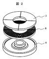
- FIG. 2 shows the structure of the rotor. In this figure, for easy understanding of the structure, each part is shown in a separated state.
- the rotor 1 includes a rotor core 6 that is formed by winding a ribbon (ribbon) of an electromagnetic steel plate such as a silicon steel plate in a spiral shape and has an annular planar shape.
- a ribbon ribbon
- an electromagnetic steel plate such as a silicon steel plate
- thin strips of electromagnetic steel sheets are laminated in an annular radial direction.
- an amorphous magnetic material may be applied to reduce the iron loss.
- the number of permanent magnets 3 equal to the number of poles of the rotor 1, that is, four permanent magnets 3 in this embodiment, are arranged and fixedly connected.
- the permanent magnets 3 corresponding to the number of poles of the rotor 1 are plate-shaped magnets each having a substantially fan-like planar shape, and are arranged in an annular shape on the annular plane of the rotor core.
- the rotor core 6 and the permanent magnet 3 are bonded by an adhesive member such as resin.
- the permanent magnet 3 a rare earth magnet or a ferrite magnet can be applied.
- the permanent magnet is not limited to the one divided into a plurality as in the present embodiment, and a single ring-shaped magnet with a plurality of poles magnetized may be used.
- the rotor core 6 is held by a rotor yoke 4 made of die cast metal.
- the rotor yoke 4 is formed of a die-cast metal on a portion of the rotor core 6 excluding a connection portion with the permanent magnet 3, that is, a flat portion on the opposite side of the flat portion to which the permanent magnet 3 is connected, that is, the back surface side in this embodiment. It is comprised by molding with. And this die-cast metal adheres to the said back surface and side surface of the rotor core 6, and the rotor core 6 is fixed to the rotor yoke 4.
- FIG. A circular hole for passing the shaft 5 is provided at the center of the rotor yoke 4.
- the shaft 5 is fixed to the rotor yoke 4 by being inserted into the hole by shrink fitting or the like.
- a nonmagnetic alloy such as an aluminum alloy is applied.
- FIG. 3 shows a spiral rotor core.
- the winding start portion and winding end portion of the electromagnetic steel sheet wound in a spiral shape are joined to the rotor core body by welding. Thereby, a spiral shape is maintained.
- the winding start portion is a ribbon end portion located on the inner wall portion of the hole in the central portion of the rotor core 6, and the winding end is the outermost peripheral portion of the rotor core 6. It is a ribbon end part located in a side part.
- the rotor core 6 may be resin-molded. At this time, the surface of the resin is lower than the laminated surface A of the rotor core 6. This prevents the resin from affecting the gap size between the stator and the rotor.
- the resin molding process may be executed after the die casting process using a high-temperature molten metal.
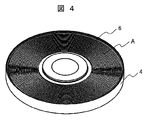
- FIG. 4 shows the rotor core fixed to the rotor yoke.
- the rotor yoke 4 made of die-cast metal includes the entire laminated surface of the rotor core 6 on the back side of the laminated surface A exposed in the drawing, the outermost circumferential side surface and the innermost circumferential surface of the rotor core 6. It coats the side surfaces and adheres to these coated surfaces. That is, a portion of the rotor core 6 excluding the laminated surface A on which the permanent magnet 3 is disposed is molded with die-cast metal. Since the rotor core 6 is molded into die-cast metal, deformation of the spiral rotor core 6 is suppressed.
- the die-cast metal which comprises the rotor yoke 4 may be located between the laminated
- the rotor core 6 is securely fixed to the stator yoke 4.
- the die-cast metal surface can be made lower than the laminated surface A, and the laminated surface A on which the permanent magnet 3 is placed can be made flat.
- Such an integral configuration of the rotor yoke 4 and the rotor core 6 improves the strength of the rotor while using the rotor core 6 in which the electromagnetic steel sheet ribbon is wound in a spiral shape. Furthermore, since the shaft 5 is fixed to the rotor yoke 4 made of die-cast metal, the shaft 5 is fixed to the spiral rotor core 6 via the rotor yoke 4. Thereby, the fixed strength between the spiral rotor core 6 and the shaft 5 is improved. Further, the rotor yoke 4 made of die-cast metal improves the dimensional accuracy of the rotor, so that the gaps between the rotor and the stator can be made uniform.
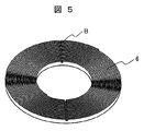
- FIG. 5 shows a modification of the rotor core.
- This variation is configured by winding a magnetic steel sheet ribbon in a spiral shape as in the embodiment of FIG. 3, but unlike the rotor core of FIG. 3, grooves B are provided in the radial direction of the laminated surface.
- the molten die-cast metal can surely flow into the inner peripheral side, the interlayer and the outer peripheral side of the rotor core housed in the mold jig and spread.
- the rotor yoke 4 can be manufactured with an accurate shape and with high dimensional accuracy.
- FIG. 6 is a perspective view (a) and a sectional view (b) of a rotor to which a permanent magnet is connected.
- the plate-like permanent magnet 3 is placed on the laminated surface of the rotor core, and is bonded and fixed by an adhesive member such as resin or adhesive.
- the rotor yoke 4 has a step in the outer peripheral portion and the inner peripheral portion. That is, the outer peripheral portion and the inner peripheral portion of the rotor yoke 4 are higher than the laminated surface of the rotor core 6, so that the integrated rotor yoke 4 and rotor core 6 are combined with the rotor core 6.
- a recess having a bottom surface of the laminated surface In this recess, the permanent magnet 3 is bonded onto the laminated surface of the rotor core 6 and the lower part of the step of the rotor yoke 4 in contact therewith. Therefore, the permanent magnet 3 is accurately positioned at a predetermined position with respect to the rotor core 6 by the step portion of the rotor yoke 4.
- a cylindrical portion that forms a hole through which the shaft 5 passes is provided in the central portion of the rotor yoke 4.
- the shaft 5 passes through this hole and is fixed to the rotor yoke 4 at the cylindrical portion.
- the rotor yoke 4 is configured by molding a portion of the rotor core 6 excluding the laminated surface A on which the permanent magnet 3 is disposed with die-cast metal. Then, the die-cast metal constituting the rotor yoke 4 adheres to the rotor core 6 so that the rotor core 6 is fixed to the rotor yoke 4. Thereby, the dimensional accuracy of the rotor is improved and the strength of the rotor is improved. Since the dimensional accuracy of the rotor is improved, it is easy to adjust the gap between the rotor and the stator. Therefore, the rotation of the axial gap type motor can be stabilized. Furthermore, since the strength of the rotor can be improved, the speed of the axial gap motor can be increased.
- a rotor yoke is formed by molding the rotor core with die-cast metal, and at the same time, the rotor core and the rotor yoke are integrated. Thereby, the manufacturing process of a motor can be simplified and manufacturing cost can be reduced.
- FIG. 7 shows a part (a) of a rotor core of an axial gap type motor that is Embodiment 2 of the present invention, and a rotor (b) on which no permanent magnet is placed.
- a part of the rotor core 6 in the present embodiment is configured by laminating thin strips of electromagnetic steel sheets that gradually increase in length toward the outer peripheral side in the radial direction, It has a substantially fan shape.
- the laminated ribbons are brought into close contact and joined by welding or the like.
- a plurality of substantially fan-shaped rotor core portions shown in FIG. 7A are arranged in an annular shape as shown in FIG. 7B.
- the space factor of the rotor core that is, the volume ratio of the magnetic material in the rotor core is improved, so that the output of the axial gap motor can be improved.
- the annular rotor core is divided into a plurality of fan-shaped rotor core portions in the circumferential direction, eddy current loss can be reduced.
- FIG. 8 shows a rotor (a) in which a permanent magnet of an axial gap type motor that is Embodiment 3 of the present invention is not mounted, and a structural member (b) of the rotor.
- a substantially fan-shaped and elongated structural member 7 composed of a plurality of fan-shaped rotor cores similar to those in FIG. Are arranged alternately and in an annular shape.
- the structural member 7 may be either a magnetic material or a non-magnetic material.
- the motor performance can be appropriately adjusted depending on the number and size of the rotor cores and the structural members on which the electromagnetic steel sheet ribbons are laminated. .
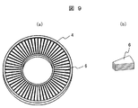
- FIG. 9 shows a rotor (a) where a permanent magnet of an axial gap type motor that is Embodiment 4 of the present invention is not mounted, and a part (b) of the rotor core.
- a plurality of thin and substantially fan-shaped electromagnetic steel sheets are laminated in the thickness direction of the rotor core.
- Such a rotor core portion is arranged in an annular shape as shown in FIG.
- eddy current loss can be reduced.
- FIG. 10 is a schematic view showing a method for manufacturing a rotor of an axial gap type motor that is Embodiment 5 of the present invention.
- This figure is a perspective view (a) showing how the motor component is assembled in the jig, and a sectional view (b) taken along the line AA 'in the perspective view.
- the substantially cylindrical mold jig 30 and the substantially cylindrical mold jig 31 are closed.
- FIG. 10B each part is illustrated separately for easy understanding of the figure.
- the space in the mold jig is sealed except for the molten metal inlet C.
- a laminated surface that is a joint surface with the permanent magnet in the rotor core 6 is in close contact with the mold jig 31.
- molten die-cast metal is injected into the space in the mold jig from the molten metal injection port C while applying pressure by a pressure device (not shown).
- a pressure device not shown
- a rotor yoke made of die-cast metal for molding the back side of the joint surface with the permanent magnet of the rotor core 6 as described above is formed.
- a cylindrical protrusion is provided at the center of the mold jig 31.
- the upper surface of this protrusion that is, the circular surface on the left side of the columnar protrusion in FIG. 10A, is in close contact with the mold jig 30 with the mold jigs 30 and 31 closed.
- An annular groove is formed around the protrusion.
- an integral structure of the rotor core and the rotor yoke in the rotor of the axial gap motor of the first embodiment can be manufactured.
- the present invention is not limited to an axial gap type motor in which two rotors sandwich one stator as shown in FIG. 1, but one having one rotor and one stator,
- the present invention can also be applied to a case where the stator sandwiches one rotor.
- the present invention can also be applied to an axial gap generator.
Landscapes
- Engineering & Computer Science (AREA)
- Power Engineering (AREA)
- Iron Core Of Rotating Electric Machines (AREA)
- Permanent Field Magnets Of Synchronous Machinery (AREA)
- Permanent Magnet Type Synchronous Machine (AREA)
Applications Claiming Priority (2)
| Application Number | Priority Date | Filing Date | Title |
|---|---|---|---|
| JP2014-088773 | 2014-04-23 | ||
| JP2014088773A JP6360709B2 (ja) | 2014-04-23 | 2014-04-23 | アキシャルギャップ型回転電機 |
Publications (1)
| Publication Number | Publication Date |
|---|---|
| WO2015162961A1 true WO2015162961A1 (ja) | 2015-10-29 |
Family
ID=54332135
Family Applications (1)
| Application Number | Title | Priority Date | Filing Date |
|---|---|---|---|
| PCT/JP2015/052682 Ceased WO2015162961A1 (ja) | 2014-04-23 | 2015-01-30 | アキシャルギャップ型回転電機 |
Country Status (3)
| Country | Link |
|---|---|
| JP (1) | JP6360709B2 (enExample) |
| TW (1) | TWI536713B (enExample) |
| WO (1) | WO2015162961A1 (enExample) |
Families Citing this family (1)
| Publication number | Priority date | Publication date | Assignee | Title |
|---|---|---|---|---|
| JP2018064402A (ja) * | 2016-10-14 | 2018-04-19 | マツダ株式会社 | アキシャルギャップ型回転電機 |
Citations (4)
| Publication number | Priority date | Publication date | Assignee | Title |
|---|---|---|---|---|
| JPS5657639U (enExample) * | 1979-10-11 | 1981-05-18 | ||
| JP2008220128A (ja) * | 2007-03-07 | 2008-09-18 | Daikin Ind Ltd | アキシャルギャップ型回転電機及び圧縮機 |
| JP2010004635A (ja) * | 2008-06-19 | 2010-01-07 | Daikin Ind Ltd | 界磁子及びその製造方法並びに回転電機 |
| JP2010166751A (ja) * | 2009-01-19 | 2010-07-29 | Daikin Ind Ltd | コア及び回転電機 |
Family Cites Families (1)
| Publication number | Priority date | Publication date | Assignee | Title |
|---|---|---|---|---|
| JP5027169B2 (ja) * | 2009-01-30 | 2012-09-19 | 本田技研工業株式会社 | アキシャルギャップ型モータ及びそのロータ製造方法 |
-
2014
- 2014-04-23 JP JP2014088773A patent/JP6360709B2/ja not_active Expired - Fee Related
- 2014-12-22 TW TW103144777A patent/TWI536713B/zh not_active IP Right Cessation
-
2015
- 2015-01-30 WO PCT/JP2015/052682 patent/WO2015162961A1/ja not_active Ceased
Patent Citations (4)
| Publication number | Priority date | Publication date | Assignee | Title |
|---|---|---|---|---|
| JPS5657639U (enExample) * | 1979-10-11 | 1981-05-18 | ||
| JP2008220128A (ja) * | 2007-03-07 | 2008-09-18 | Daikin Ind Ltd | アキシャルギャップ型回転電機及び圧縮機 |
| JP2010004635A (ja) * | 2008-06-19 | 2010-01-07 | Daikin Ind Ltd | 界磁子及びその製造方法並びに回転電機 |
| JP2010166751A (ja) * | 2009-01-19 | 2010-07-29 | Daikin Ind Ltd | コア及び回転電機 |
Also Published As
| Publication number | Publication date |
|---|---|
| JP2015208176A (ja) | 2015-11-19 |
| TWI536713B (zh) | 2016-06-01 |
| TW201541816A (zh) | 2015-11-01 |
| JP6360709B2 (ja) | 2018-07-18 |
Similar Documents
| Publication | Publication Date | Title |
|---|---|---|
| CN102111028B (zh) | 轴向间隙型旋转电机以及其中所使用的转子 | |
| CN107005103B (zh) | 旋转电机用定子铁芯、旋转电机及旋转电机的制造方法 | |
| JP5398512B2 (ja) | アキシャルギャップ型永久磁石モータ、それに用いるロータ、及びそのロータの製造方法 | |
| JP5128538B2 (ja) | アキシャルギャップ型回転電機 | |
| CN107408852B (zh) | 转子、旋转电机以及转子的制造方法 | |
| JP2012161226A (ja) | 回転電機用回転子 | |
| CN101741153A (zh) | 电枢铁心、使用了该电枢铁心的电动机、轴向间隙型旋转电动机、及其制造方法 | |
| JPH1189130A (ja) | モータ構造 | |
| JP6584331B2 (ja) | 単相ブラシレスモータおよび単相ブラシレスモータの製造方法 | |
| JP2000253635A (ja) | アキシャルギャップモータ | |
| US20120248930A1 (en) | Wound core, electromagnetic component and manufacturing method therefor, and electromagnetic equipment | |
| JP2012244838A (ja) | 回転電機用ロータ、回転電機、および、回転電機用ロータの製造方法 | |
| WO2016056294A1 (ja) | アキシャルギャップ型回転電機およびその製造方法 | |
| WO2020137549A1 (ja) | コア、ステータ、及び回転電機 | |
| CN114448129A (zh) | 无外磁桥电机转子 | |
| JP5734148B2 (ja) | 磁石埋込型回転子及びその製造方法 | |
| JP2014057433A (ja) | 回転電気機械 | |
| JP2009284626A (ja) | 回転機器のステータ及びモータ | |
| JP6360709B2 (ja) | アキシャルギャップ型回転電機 | |
| US20200099262A1 (en) | Polyphase claw pole motor | |
| US20170093232A1 (en) | Axial Air Gap Type Electric Motor | |
| JP2019208360A (ja) | モータ、モータの製造方法、モータを備えた電気掃除機、および電気掃除機の製造方法 | |
| US11742709B2 (en) | Axial gap motor having a void portion provided for the increased torque of said motor | |
| JP5311877B2 (ja) | ステータのコイル及び回転機器のステータコア | |
| JP2019097258A (ja) | 回転電機用磁性くさび、回転電機用磁性くさびの製造方法、および、回転電機 |
Legal Events
| Date | Code | Title | Description |
|---|---|---|---|
| 121 | Ep: the epo has been informed by wipo that ep was designated in this application |
Ref document number: 15782392 Country of ref document: EP Kind code of ref document: A1 |
|
| NENP | Non-entry into the national phase |
Ref country code: DE |
|
| 122 | Ep: pct application non-entry in european phase |
Ref document number: 15782392 Country of ref document: EP Kind code of ref document: A1 |