WO2015159961A1 - Autonomous traveling body - Google Patents
Autonomous traveling body Download PDFInfo
- Publication number
- WO2015159961A1 WO2015159961A1 PCT/JP2015/061761 JP2015061761W WO2015159961A1 WO 2015159961 A1 WO2015159961 A1 WO 2015159961A1 JP 2015061761 W JP2015061761 W JP 2015061761W WO 2015159961 A1 WO2015159961 A1 WO 2015159961A1
- Authority
- WO
- WIPO (PCT)
- Prior art keywords
- main body
- imaging
- body case
- unit
- obstacle
- Prior art date
Links
- 238000003384 imaging method Methods 0.000 claims abstract description 118
- 238000001514 detection method Methods 0.000 claims description 58
- 238000004891 communication Methods 0.000 claims description 15
- 238000005259 measurement Methods 0.000 claims description 3
- 238000004140 cleaning Methods 0.000 description 45
- 239000000428 dust Substances 0.000 description 19
- 230000006870 function Effects 0.000 description 19
- 238000000034 method Methods 0.000 description 14
- 230000005540 biological transmission Effects 0.000 description 12
- 230000008569 process Effects 0.000 description 9
- 230000000694 effects Effects 0.000 description 5
- 238000012545 processing Methods 0.000 description 5
- 230000007704 transition Effects 0.000 description 5
- 239000007789 gas Substances 0.000 description 4
- 230000004044 response Effects 0.000 description 4
- 230000009471 action Effects 0.000 description 3
- 230000008859 change Effects 0.000 description 3
- 230000002265 prevention Effects 0.000 description 3
- UGFAIRIUMAVXCW-UHFFFAOYSA-N Carbon monoxide Chemical compound [O+]#[C-] UGFAIRIUMAVXCW-UHFFFAOYSA-N 0.000 description 2
- 229910002091 carbon monoxide Inorganic materials 0.000 description 2
- 230000007246 mechanism Effects 0.000 description 2
- 238000012544 monitoring process Methods 0.000 description 2
- 230000002093 peripheral effect Effects 0.000 description 2
- 230000002159 abnormal effect Effects 0.000 description 1
- 238000009933 burial Methods 0.000 description 1
- 230000009194 climbing Effects 0.000 description 1
- 238000012790 confirmation Methods 0.000 description 1
- 238000001816 cooling Methods 0.000 description 1
- 238000012937 correction Methods 0.000 description 1
- 238000010586 diagram Methods 0.000 description 1
- 239000011521 glass Substances 0.000 description 1
- 210000004209 hair Anatomy 0.000 description 1
- 238000005286 illumination Methods 0.000 description 1
- 230000006698 induction Effects 0.000 description 1
- 238000012986 modification Methods 0.000 description 1
- 230000004048 modification Effects 0.000 description 1
- 230000003287 optical effect Effects 0.000 description 1
- 238000005192 partition Methods 0.000 description 1
- 229920003002 synthetic resin Polymers 0.000 description 1
- 239000000057 synthetic resin Substances 0.000 description 1
- 239000002341 toxic gas Substances 0.000 description 1
- 238000012546 transfer Methods 0.000 description 1
Images


Classifications
-
- A—HUMAN NECESSITIES
- A47—FURNITURE; DOMESTIC ARTICLES OR APPLIANCES; COFFEE MILLS; SPICE MILLS; SUCTION CLEANERS IN GENERAL
- A47L—DOMESTIC WASHING OR CLEANING; SUCTION CLEANERS IN GENERAL
- A47L9/00—Details or accessories of suction cleaners, e.g. mechanical means for controlling the suction or for effecting pulsating action; Storing devices specially adapted to suction cleaners or parts thereof; Carrying-vehicles specially adapted for suction cleaners
- A47L9/28—Installation of the electric equipment, e.g. adaptation or attachment to the suction cleaner; Controlling suction cleaners by electric means
- A47L9/2836—Installation of the electric equipment, e.g. adaptation or attachment to the suction cleaner; Controlling suction cleaners by electric means characterised by the parts which are controlled
- A47L9/2852—Elements for displacement of the vacuum cleaner or the accessories therefor, e.g. wheels, casters or nozzles
-
- G—PHYSICS
- G05—CONTROLLING; REGULATING
- G05D—SYSTEMS FOR CONTROLLING OR REGULATING NON-ELECTRIC VARIABLES
- G05D1/00—Control of position, course or altitude of land, water, air, or space vehicles, e.g. automatic pilot
- G05D1/0094—Control of position, course or altitude of land, water, air, or space vehicles, e.g. automatic pilot involving pointing a payload, e.g. camera, weapon, sensor, towards a fixed or moving target
-
- A—HUMAN NECESSITIES
- A47—FURNITURE; DOMESTIC ARTICLES OR APPLIANCES; COFFEE MILLS; SPICE MILLS; SUCTION CLEANERS IN GENERAL
- A47L—DOMESTIC WASHING OR CLEANING; SUCTION CLEANERS IN GENERAL
- A47L9/00—Details or accessories of suction cleaners, e.g. mechanical means for controlling the suction or for effecting pulsating action; Storing devices specially adapted to suction cleaners or parts thereof; Carrying-vehicles specially adapted for suction cleaners
- A47L9/009—Carrying-vehicles; Arrangements of trollies or wheels; Means for avoiding mechanical obstacles
-
- A—HUMAN NECESSITIES
- A47—FURNITURE; DOMESTIC ARTICLES OR APPLIANCES; COFFEE MILLS; SPICE MILLS; SUCTION CLEANERS IN GENERAL
- A47L—DOMESTIC WASHING OR CLEANING; SUCTION CLEANERS IN GENERAL
- A47L9/00—Details or accessories of suction cleaners, e.g. mechanical means for controlling the suction or for effecting pulsating action; Storing devices specially adapted to suction cleaners or parts thereof; Carrying-vehicles specially adapted for suction cleaners
- A47L9/02—Nozzles
- A47L9/04—Nozzles with driven brushes or agitators
- A47L9/0405—Driving means for the brushes or agitators
- A47L9/0411—Driving means for the brushes or agitators driven by electric motor
-
- A—HUMAN NECESSITIES
- A47—FURNITURE; DOMESTIC ARTICLES OR APPLIANCES; COFFEE MILLS; SPICE MILLS; SUCTION CLEANERS IN GENERAL
- A47L—DOMESTIC WASHING OR CLEANING; SUCTION CLEANERS IN GENERAL
- A47L9/00—Details or accessories of suction cleaners, e.g. mechanical means for controlling the suction or for effecting pulsating action; Storing devices specially adapted to suction cleaners or parts thereof; Carrying-vehicles specially adapted for suction cleaners
- A47L9/28—Installation of the electric equipment, e.g. adaptation or attachment to the suction cleaner; Controlling suction cleaners by electric means
- A47L9/2805—Parameters or conditions being sensed
- A47L9/2826—Parameters or conditions being sensed the condition of the floor
-
- A—HUMAN NECESSITIES
- A47—FURNITURE; DOMESTIC ARTICLES OR APPLIANCES; COFFEE MILLS; SPICE MILLS; SUCTION CLEANERS IN GENERAL
- A47L—DOMESTIC WASHING OR CLEANING; SUCTION CLEANERS IN GENERAL
- A47L9/00—Details or accessories of suction cleaners, e.g. mechanical means for controlling the suction or for effecting pulsating action; Storing devices specially adapted to suction cleaners or parts thereof; Carrying-vehicles specially adapted for suction cleaners
- A47L9/28—Installation of the electric equipment, e.g. adaptation or attachment to the suction cleaner; Controlling suction cleaners by electric means
- A47L9/2857—User input or output elements for control, e.g. buttons, switches or displays
-
- A—HUMAN NECESSITIES
- A47—FURNITURE; DOMESTIC ARTICLES OR APPLIANCES; COFFEE MILLS; SPICE MILLS; SUCTION CLEANERS IN GENERAL
- A47L—DOMESTIC WASHING OR CLEANING; SUCTION CLEANERS IN GENERAL
- A47L9/00—Details or accessories of suction cleaners, e.g. mechanical means for controlling the suction or for effecting pulsating action; Storing devices specially adapted to suction cleaners or parts thereof; Carrying-vehicles specially adapted for suction cleaners
- A47L9/28—Installation of the electric equipment, e.g. adaptation or attachment to the suction cleaner; Controlling suction cleaners by electric means
- A47L9/2868—Arrangements for power supply of vacuum cleaners or the accessories thereof
- A47L9/2873—Docking units or charging stations
-
- A—HUMAN NECESSITIES
- A47—FURNITURE; DOMESTIC ARTICLES OR APPLIANCES; COFFEE MILLS; SPICE MILLS; SUCTION CLEANERS IN GENERAL
- A47L—DOMESTIC WASHING OR CLEANING; SUCTION CLEANERS IN GENERAL
- A47L9/00—Details or accessories of suction cleaners, e.g. mechanical means for controlling the suction or for effecting pulsating action; Storing devices specially adapted to suction cleaners or parts thereof; Carrying-vehicles specially adapted for suction cleaners
- A47L9/28—Installation of the electric equipment, e.g. adaptation or attachment to the suction cleaner; Controlling suction cleaners by electric means
- A47L9/2894—Details related to signal transmission in suction cleaners
-
- B—PERFORMING OPERATIONS; TRANSPORTING
- B25—HAND TOOLS; PORTABLE POWER-DRIVEN TOOLS; MANIPULATORS
- B25J—MANIPULATORS; CHAMBERS PROVIDED WITH MANIPULATION DEVICES
- B25J11/00—Manipulators not otherwise provided for
- B25J11/008—Manipulators for service tasks
- B25J11/0085—Cleaning
-
- B—PERFORMING OPERATIONS; TRANSPORTING
- B25—HAND TOOLS; PORTABLE POWER-DRIVEN TOOLS; MANIPULATORS
- B25J—MANIPULATORS; CHAMBERS PROVIDED WITH MANIPULATION DEVICES
- B25J19/00—Accessories fitted to manipulators, e.g. for monitoring, for viewing; Safety devices combined with or specially adapted for use in connection with manipulators
- B25J19/02—Sensing devices
- B25J19/021—Optical sensing devices
- B25J19/023—Optical sensing devices including video camera means
-
- B—PERFORMING OPERATIONS; TRANSPORTING
- B25—HAND TOOLS; PORTABLE POWER-DRIVEN TOOLS; MANIPULATORS
- B25J—MANIPULATORS; CHAMBERS PROVIDED WITH MANIPULATION DEVICES
- B25J9/00—Programme-controlled manipulators
- B25J9/0003—Home robots, i.e. small robots for domestic use
-
- B—PERFORMING OPERATIONS; TRANSPORTING
- B25—HAND TOOLS; PORTABLE POWER-DRIVEN TOOLS; MANIPULATORS
- B25J—MANIPULATORS; CHAMBERS PROVIDED WITH MANIPULATION DEVICES
- B25J9/00—Programme-controlled manipulators
- B25J9/16—Programme controls
- B25J9/1615—Programme controls characterised by special kind of manipulator, e.g. planar, scara, gantry, cantilever, space, closed chain, passive/active joints and tendon driven manipulators
- B25J9/162—Mobile manipulator, movable base with manipulator arm mounted on it
-
- B—PERFORMING OPERATIONS; TRANSPORTING
- B25—HAND TOOLS; PORTABLE POWER-DRIVEN TOOLS; MANIPULATORS
- B25J—MANIPULATORS; CHAMBERS PROVIDED WITH MANIPULATION DEVICES
- B25J9/00—Programme-controlled manipulators
- B25J9/16—Programme controls
- B25J9/1656—Programme controls characterised by programming, planning systems for manipulators
- B25J9/1664—Programme controls characterised by programming, planning systems for manipulators characterised by motion, path, trajectory planning
- B25J9/1666—Avoiding collision or forbidden zones
-
- G—PHYSICS
- G05—CONTROLLING; REGULATING
- G05D—SYSTEMS FOR CONTROLLING OR REGULATING NON-ELECTRIC VARIABLES
- G05D1/00—Control of position, course or altitude of land, water, air, or space vehicles, e.g. automatic pilot
- G05D1/0011—Control of position, course or altitude of land, water, air, or space vehicles, e.g. automatic pilot associated with a remote control arrangement
- G05D1/0022—Control of position, course or altitude of land, water, air, or space vehicles, e.g. automatic pilot associated with a remote control arrangement characterised by the communication link
-
- G—PHYSICS
- G05—CONTROLLING; REGULATING
- G05D—SYSTEMS FOR CONTROLLING OR REGULATING NON-ELECTRIC VARIABLES
- G05D1/00—Control of position, course or altitude of land, water, air, or space vehicles, e.g. automatic pilot
- G05D1/02—Control of position or course in two dimensions
- G05D1/021—Control of position or course in two dimensions specially adapted to land vehicles
- G05D1/0231—Control of position or course in two dimensions specially adapted to land vehicles using optical position detecting means
- G05D1/0238—Control of position or course in two dimensions specially adapted to land vehicles using optical position detecting means using obstacle or wall sensors
-
- A—HUMAN NECESSITIES
- A47—FURNITURE; DOMESTIC ARTICLES OR APPLIANCES; COFFEE MILLS; SPICE MILLS; SUCTION CLEANERS IN GENERAL
- A47L—DOMESTIC WASHING OR CLEANING; SUCTION CLEANERS IN GENERAL
- A47L2201/00—Robotic cleaning machines, i.e. with automatic control of the travelling movement or the cleaning operation
- A47L2201/02—Docking stations; Docking operations
- A47L2201/022—Recharging of batteries
-
- A—HUMAN NECESSITIES
- A47—FURNITURE; DOMESTIC ARTICLES OR APPLIANCES; COFFEE MILLS; SPICE MILLS; SUCTION CLEANERS IN GENERAL
- A47L—DOMESTIC WASHING OR CLEANING; SUCTION CLEANERS IN GENERAL
- A47L2201/00—Robotic cleaning machines, i.e. with automatic control of the travelling movement or the cleaning operation
- A47L2201/04—Automatic control of the travelling movement; Automatic obstacle detection
Definitions
- Embodiment of this invention is related with the autonomous running body provided with the imaging part which can image a to-be-photographed object.
- a vacuum cleaner can automatically capture an indoor state with a camera in response to a command from a portable terminal.
- an image can be captured in the widest possible range without blind spots and without being obstructed by obstacles.
- the problem to be solved by the present invention is to provide an autonomous traveling body capable of reliably imaging a wide range without a blind spot by an imaging unit.
- the autonomous traveling body of the embodiment includes a main body case, an imaging unit that is provided in the main body case and can capture an image with a predetermined angle of view, driving wheels that can travel the main body case, and a control unit.
- This control unit has at least a traveling mode and an imaging mode.
- the traveling mode the control unit causes the main body case to autonomously travel by controlling the driving of the driving wheels.
- the image capturing mode the control unit causes the main body case to autonomously travel to a predetermined image capturing position, and causes the image capturing unit to capture still images in a plurality of directions that are successively adjacent at an angle equal to or smaller than the angle of view.
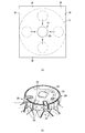
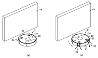
- the autonomous traveling body of 1st Embodiment is shown, (a) is a top view which shows typically the moving method to an imaging position, (b) is a perspective view which shows the operation
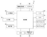
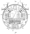
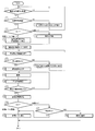
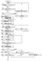
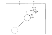
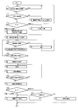
- It is a block diagram which shows the internal structure of an autonomous traveling body same as the above. It is explanatory drawing which shows typically the system containing an autonomous traveling body same as the above. It is a top view which shows an autonomous running body same as the above from the lower part. It is a flowchart which shows the control at the time of the imaging mode of an autonomous running body same as the above. It is a perspective view which shows typically the movement method to the imaging position of the autonomous running body of 2nd Embodiment.
- reference numeral 10 denotes a vacuum cleaner as a traveling body device.
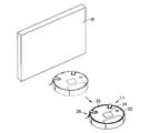
- the vacuum cleaner 10 includes a vacuum cleaner body 11 as an autonomous traveling body, and a charging base for the vacuum cleaner body 11. And a charging device (charging stand) 12 as a part.
- the vacuum cleaner main body 11 is connected to an access point 14 as a relay means (relay unit) such as a home gateway (router) disposed in a room R that is a cleaning area, for example. ) Or Bluetooth (registered trademark) or the like for communication (transmission / reception), it is possible to perform wireless communication with an external device 16 such as a mobile phone via an (external) network 15 such as the Internet.
- a relay means such as a home gateway (router) disposed in a room R that is a cleaning area, for example.
- Bluetooth registered trademark
- the main body 11 of the electric vacuum cleaner is a so-called self-propelled robot cleaner that cleans the floor surface while autonomously traveling (self-propelled) on the floor surface as the surface to be cleaned.
- this electric vacuum cleaner main body 11 has a hollow main body case 20 as a running / cleaning part, an electric blower 21 as an operation part (cleaning part) accommodated in the main body case 20, and an intake of the electric blower 21 Dust collecting unit 22 communicating with the side, for example, driving wheels 23 and 23 as a plurality of (a pair of) driving units for traveling, and a motor as a driving means (driving unit) as an operating unit for driving these driving wheels 23 and 23 24, 24, turning wheel 25 for turning, auxiliary cleaning means (auxiliary cleaning part) as, for example, a plurality (a pair) of turning cleaning parts (cleaning parts) arranged so as to be turnable along the floor surface at the bottom of the body case 20 )
- the vacuum cleaner main body 11 includes, as an input / output / control unit, a sensor unit 31 as an operation unit having various sensors, a display unit 34 as a display unit, a camera 35 as an imaging unit (imaging unit), wireless communication A wireless LAN device 36 as means (wireless communication unit) and a control unit (control means) 37 constituted by a circuit board and the like are provided.
- the vacuum cleaner main body 11 includes a secondary battery 39 in the main body case 20 for supplying power to each of the above parts.
- the direction along the traveling direction of the vacuum cleaner main body 11 (main body case 20) will be referred to as the front-rear direction (arrows FR and RR shown in FIG. 3 and the like), and left and right intersecting (orthogonal) with respect to the front-rear direction.
- the direction (both sides) will be described as the width direction.
- the main body case 20 is formed into a flat columnar shape (disk shape) by, for example, synthetic resin, etc., and is long in the width direction, that is, horizontally long at a position near the rear portion of the center portion in the width direction of the circular bottom surface.
- the suction port 41 is opened, and a plurality of exhaust ports 42 are opened in front of the suction port 41. Further, a camera 35 is disposed in the main body case 20.
- the suction port 41 is in communication with the suction side of the electric blower 21 through the dust collecting unit 22.
- the rotary brush 28 is rotatably disposed in the suction port 41.
- the exhaust port 42 communicates with the exhaust side of the electric blower 21 through the dust collecting unit 22.
- the electric blower 21 generates negative pressure by driving and sucks dust from the suction port 41 to the dust collecting part 22.
- the suction side is directed rearward and the axial direction is the front-rear direction (horizontal direction).
- the electric blower 21 may not be necessary in the case of, for example, a configuration in which dust is scraped up to the dust collection unit 22 by the rotating brush 28 or the like, and is not an essential configuration.
- the dust collecting unit 22 collects dust sucked from the suction port 41 by driving the electric blower 21.
- Each driving wheel 23 is for traveling (autonomous traveling) the vacuum cleaner body 11 (main body case 20) in the forward and backward directions on the floor surface, that is, for traveling, not shown along the left-right width direction. It has a rotation axis and is arranged symmetrically in the width direction.
- Each motor 24 is arranged corresponding to each of the drive wheels 23, for example, and can drive each drive wheel 23 independently.
- the turning wheel 25 is a driven wheel that is located at the front and substantially at the center in the width direction of the main body case 20 and can turn along the floor surface.
- Each side brush 26 has brush hairs 43 as a plurality of (for example, three) cleaning bodies that project radially and come into contact with the floor surface.
- the side brushes 26 and 26 are disposed at positions on both sides of the main body case 20 in front of the drive wheels 23 and 23 and behind the swivel wheel 25.
- Each side brush motor 27 moves each side brush 26 to the center side in the width direction of the body case 20, in other words, the right side brush 26 to the left side, and the left side brush 26 to the right side, that is, each side.
- the brushes 26 can be rotated so that dust in the front (traveling direction) is scraped to the suction port 41 side.
- the side brush 26 and the side brush motor 27 are not indispensable as long as they can be sufficiently cleaned by the electric blower 21 or the rotating brush 28.
- the rotary brush 28 is formed in a long shape, and both ends are pivotally supported on both sides in the width direction of the suction port 41 so as to be rotatable.
- the rotating brush 28 protrudes downward from the lower surface of the main body case 20 through the suction port 41, and the lower part contacts the floor surface while the vacuum cleaner main body 11 is placed on the floor surface, and dust is collected. It is configured to scrape.
- the brush motor 29 is accommodated in the main body case 20, and is connected to the rotating brush 28 via a gear mechanism (not shown) as a mechanism portion.
- the rotating brush 28 and the brush motor 29 are not essential components as long as they can be sufficiently cleaned by the electric blower 21 or the side brushes 26 and 26.
- the sensor unit 31 detects an obstacle by detecting a distance from an obstacle such as a wall or furniture, for example, a revolution number detection means (a revolution number detection unit) such as an optical encoder that measures the number of revolutions of the motor 24.
- Obstacle detection means (obstacle detection part) that is a distance measurement means (ranging part) such as an ultrasonic sensor or an infrared sensor, and a step detection means (step difference) such as an infrared sensor that detects a step on the floor surface.
- a function such as a detection unit, and is disposed in each part such as an upper part, an outer peripheral part (a front part and a rear part), and a lower part of the main body case 20.
- the display unit 34 displays time and time, or various information related to the vacuum cleaner main body 11, and is disposed, for example, on the upper portion of the main body case 20.
- the display unit 34 may be, for example, a touch panel that also has a function of an input operation unit (input operation unit) that allows the user to directly input various settings.
- the camera 35 includes a camera module as an imaging means body (imaging unit body) for imaging, and an illumination device such as an LED that is turned on by the control unit 37 during imaging.
- the camera 35 is disposed, for example, on the outer peripheral part or the upper part of the main body case 20 at the center in the left-right direction of the front part of the main body case 20, and in a direction along the radial direction of the central axis of the main body case 20 and upward
- a still image in a region extending from the front to the upper front in the present embodiment can be imaged at a predetermined horizontal angle of view (for example, 105 °), and the captured still image is converted into data and sent to the control unit 37. It is possible to output. That is, the camera 35 is disposed at a position away from the turning center (center axis) of the main body case 20.
- the wireless LAN device 36 is for wireless communication with an external device via the access point 14 and the network 15. Accordingly, various information can be received from the network 15 and various information can be input from the external device 16 via the wireless LAN device 36. That is, the wireless LAN device 36 includes an external signal receiving unit (external signal receiving unit) and a signal receiving unit (signal receiving unit) that receive an external signal transmitted from the external device 16 via the network 15 from the access point 14. It has a function.
- the control unit 37 includes various memory areas such as a CPU that is a control unit main body, a ROM that is a storage unit that stores fixed data such as a program read by the CPU, and a work area that is a work area for data processing by the program.
- RAM which is an area storage unit that is dynamically formed, for example, a memory that is a storage unit (storage unit) such as an SDRAM that stores image data captured by the camera 35, a timer that measures calendar information such as the current date and time, and the like ing.
- This control unit 37 is electrically connected to the electric blower 21, each motor 24, each side brush motor 27, brush motor 29, sensor unit 31, display unit 34, camera 35, wireless LAN device 36, etc.
- the cleaning mode which is a traveling mode for controlling the driving of the electric blower 21, each motor 24, each side brush motor 27, the brush motor 29, etc.
- a charging mode for charging the secondary battery 39, an imaging mode for imaging by the camera 35, and a standby mode for standby operation are provided.
- the secondary battery 39 supplies power to the electric blower 21, each motor 24, each side brush motor 27, brush motor 29, sensor unit 31, camera 35, wireless LAN device 36, control unit 37, and the like.
- the secondary battery 39 is electrically connected to charging terminals 45 exposed on both sides of the rear portion of the lower surface of the main body case 20, for example.
- the charging device 12 is disposed at a position that does not interfere with cleaning, such as in the vicinity of the wall W that partitions the room R.
- a charging circuit 52 for charging a secondary battery 39 such as a constant current circuit is accommodated in a charging device case 51, and a charging terminal 53 electrically connected to the charging circuit 52 is also provided.
- 53 and the power cord 54 for power supply connected to the commercial power source are exposed to the outside of the charging device case 51, and the operation of the charging circuit 52 is controlled by the charging device control unit 58.
- the charging device control unit 58 has a charging mode for charging the secondary battery 39 via the charging circuit 52 and a standby mode for standby operation.
- the autonomously traveling electric vacuum cleaner main body 11 is roughly divided into a cleaning operation in which the electric vacuum cleaner main body 11 cleans and a charging operation in which the secondary battery 39 is charged by the charging device 12, but this embodiment Then, in addition to these operations, an imaging operation for imaging a still image such as a state in the room R is performed.
- the electric vacuum cleaner main body 11 has the electric blower 21, the drive wheels 23, 23 (the control unit 37 that has been changed from the standby mode to the cleaning mode at the cleaning start timing, for example, when a preset cleaning start time is reached).
- Motors 24, 24), side brushes 26, 26 (side brush motors 27, 27), rotating brush 28 (brush motor 29), etc. are driven, for example, detached from the charging device 12 and driven to the floor by the drive wheels 23, 23.
- the cleaning start position can be set at any place such as the travel start position of the electric vacuum cleaner main body 11 or the entrance / exit of the room R.
- the control unit 37 detects the distance from the wall portion W surrounding the periphery of the room R, an obstacle in the room R, the step difference of the floor surface, and the like through the sensor unit 31 and performs electric cleaning.
- the control unit 37 By monitoring the running state of the machine body 11 (main body case 20) and driving the drive wheels 23 and 23 (motors 24 and 24) in response to detection from the sensor unit 31, obstacles and steps are avoided. While the vacuum cleaner body 11 is running on the floor surface, for example, randomly or along the wall.
- the vacuum cleaner main body 11 collects dust to the suction port 41 by the side brushes 26 and 26 that are driven to rotate, and the suction generated by the negative pressure generated by the driving of the electric blower 21 via the dust collection unit 22 Dust on the floor surface is sucked together with air through the mouth 41.
- the rotary brush 28 that is driven to rotate scrapes off dust on the floor surface to the dust collecting unit 22.
- the dust sucked together with the air from the suction port 41 is separated and collected by the dust collecting unit 22, and the air from which the dust is separated is sucked into the electric blower 21, and after cooling the electric blower 21, it becomes exhaust air.
- the air is exhausted from the exhaust port 42 to the outside of the main body case 20.
- the electric vacuum cleaner main body 11 drives the drive wheels 23 and 23 (motors 24 and 24) by the control unit 37 and returns to the charging device 12.
- the electric vacuum cleaner main body 11 may be brought close to the charging device 12 based on a guide signal output from the charging device 12, or the room R stored in the control unit 37 in advance. You may return to the position of the charging device 12 according to the map. Then, the vacuum cleaner main body 11 connects (charging and mechanically) the charging terminal 45 to the charging terminal 53 in a state where it is moved (returned) to the charging device 12, stops each part, and finishes the cleaning work. .
- a predetermined time for example, a predetermined time after the electric vacuum cleaner main body 11 is connected to the charging device 12 when a preset charging start time is reached.
- the control unit 37 and the charging device control unit 58 shift to the charging mode, drive the charging circuit 52, and start charging the secondary battery 39.
- the control unit 37 and the charging device control unit 58 stop the charging by the charging circuit 52 to finish the charging operation, and the control unit 37 and The charging device control unit 58 is in the standby mode.
- the control unit 37 sends an imaging instruction signal, which is an external signal instructing imaging with the camera 35 transmitted from the external device 16 via the network 15, to the access point 14.
- an imaging instruction signal which is an external signal instructing imaging with the camera 35 transmitted from the external device 16 via the network 15, to the access point 14.
- the wireless LAN device 36 for example, in real time or at predetermined time intervals (step 1).
- the control unit 37 When it is determined in step 1 that the wireless LAN device 36 has received an imaging instruction signal that is an external signal instructing imaging with the camera 35 transmitted from the external device 16 via the network 15, first, the control unit 37 However, regardless of the mode, the remaining capacity of the secondary battery 39 is detected, and it is determined whether or not the remaining capacity of the secondary battery 39 is an imageable capacity that can be captured by the camera 35 (step 2).
- the imageable capacity means, for example, that the main body case 20 (the vacuum cleaner main body 11) can travel a predetermined distance or more, and the network 15 through the wireless LAN device 36 captures the image data captured by the camera 35 and the captured image data. To a capacity that can be transmitted to the external device 16.
- step 2 If it is determined in step 2 that the remaining capacity of the secondary battery 39 is not an imageable capacity, the control unit 37 uses the wireless LAN device 36 to notify the external device 16 that imaging is not possible, for example. (Step 3), the imaging instruction signal is ignored and the process returns to Step 1.
- step 4 determines whether the remaining capacity of the secondary battery 39 is greater than or equal to the imageable capacity. If it is determined in step 2 that the remaining capacity of the secondary battery 39 is greater than or equal to the imageable capacity, the control unit 37 (and the charging device control unit 58) determines the mode (step 4).
- step 4 If it is determined in step 4 that the charging mode or the standby mode is set, the control unit 37 drives the driving wheels 23 and 23 (motors 24 and 24) to separate the vacuum cleaner main body 11 from the charging device 12. (Step 5), and shift to the imaging mode (step 6).
- step 4 when it is determined in step 4 that the cleaning mode is set, the control unit 37 controls, for example, the electric blower 21, the side brushes 26 and 26 (side brush motors 27 and 27), and the rotating brush 28 (brush motor 29).
- the driving is stopped to stop the cleaning (step 7), and the process proceeds to step 6 to shift to the imaging mode.
- the control unit 37 drives the drive wheels 23, 23 (motors 24, 24) to turn the main body case 20, while the sensor unit 31 fails.
- the distance between the main body case 20 and an obstacle such as a wall W around the main body case 20 is measured by the function of the object detection unit (ranging unit) (step 8), and the measured distance is a predetermined predetermined distance or more.
- the control unit 37 determines whether it is 2 m or more (step 9).
- the main body case 20 turns 360 ° in the present embodiment, for example, but may have a predetermined angle of less than 360 ° or the like according to the range captured by the camera 35 or the like.
- the turning of the main body case 20 means that one driving wheel 23 (one motor 24) and the other driving wheel 23 (the other motor 24) rotate in opposite directions.
- it is said to turn so as to turn around the central axis of the main body case 20, but is not limited to this, but is not limited to this, for example, a predetermined radius around a predetermined turning center This includes the case where the vehicle travels in a circle so as to turn.
- step 9 for example, when it is determined that the distance between the main body case 20 and the obstacles around the main body case 20 is not a predetermined distance (2 m) or more (less than the predetermined distance (2 m)), the control unit 37 drives the drive wheels 23 and 23 (motors 24 and 24) to cause the main body case 20 to travel away from the obstacle (wall portion W, etc.) (step 10, FIG. 1 (a)).
- the distance traveled at this time is, for example, equal to or greater than the difference between the predetermined distance used in the determination in step 9 and the distance between the main body case 20 and the obstacle, or the predetermined distance itself. It can be separated by more than a distance.
- Step 9 when it is determined that the distance between the main body case 20 and the obstacles around the main body case 20 is a predetermined distance (2 m) or more, the main body case 20 (the electric vacuum cleaner main body 11) It is determined that there is no wall portion W or the like within a predetermined distance around the center of the room R, and that position is set as an imaging position (step 11).
- control unit 37 captures an image with the camera 35 at that position (step 12), and the control unit 37 drives the drive wheels 23 and 23 (motors 24 and 24) so that the main body case 20 moves the horizontal angle of view of the camera 35.
- the following predetermined angle preferably a predetermined angle equal to or less than half of the horizontal angle of view, for example, 30 ° leftward (or rightward) in this embodiment is turned (step 13, FIG. 1 (b)).
- the control unit 37 determines whether or not the main body case 20 has turned at a predetermined imaging angle larger than the angle of view of the camera 35 at the imaging position, for example, 360 ° or more (step 14), and a predetermined imaging angle (360 °).
- the process returns to step 12.
- the vacuum cleaner main body 11 can capture still images in a plurality of directions that are sequentially adjacent at an angle equal to or smaller than the horizontal angle of view of the camera 35 by a predetermined imaging angle (for example, 360 °). Therefore, these still images have portions that gradually overlap each other, and in this embodiment, more than half of the still images adjacent to each other overlap, and as a whole, the still images without a blind spot over a predetermined imaging angle. Is imaged.
- the control unit 37 converts the plurality of still images captured and output by the camera 35 into a predetermined image format, for example.
- the wireless LAN device 36 wirelessly transmits a panorama image obtained by compressing and temporarily storing the compressed image in the memory, and processing each still image or an overlapping portion from an adjacent still image (step 15).
- the wirelessly transmitted image data is stored in a server 59 connected to the network 15, and can be remotely confirmed via the external device 16 at an arbitrary timing.
- control unit 37 determines the mode immediately before shifting to the imaging mode (step 16).
- the control unit 37 returns the vacuum cleaner main body 11 to the charging device 12 in the same manner as during the cleaning operation, and the charging mode is transferred to the charging mode together with the charging device control unit 58. (Step 17).
- step 16 when it is determined in step 16 that the cleaning mode is set (the cleaning mode is interrupted and the mode is changed to the imaging mode), the control unit 37 compares the capacity of the secondary battery 39 with the remaining capacity required for cleaning. It is determined whether or not the capacity is sufficient (step 18), and when it is determined that the capacity is sufficient, the control unit 37 controls the electric blower 21, the side brushes 26 and 26 (side brush motors 27 and 27), and the rotating brush 28 (brush motor 29). Drive to return to cleaning (step 19), and if it is determined that the capacity is insufficient, proceed to step 17 and return the vacuum cleaner body 11 to the charging device 12 and shift to the charging mode as in the cleaning operation. To do.
- the control may be performed such that the transition to the charging mode is always performed when the imaging mode ends.
- the standby mode may be shifted as it is, or only when the mode immediately before the transition to the imaging mode is the cleaning mode after the charging. You may return to cleaning.
- the function of the obstacle detecting unit which is the distance measuring unit of the sensor unit 31 is within a certain distance around the main body case 20 (in the virtual circle C in FIG. 1A). ), The position where no obstacle is detected is set as the imaging position, so that the room can be effectively imaged by the camera 35 without being obstructed by the obstacle, and the state of the room can be confirmed more easily.
- the second embodiment is different from the first embodiment in the method of moving the main body case 20 (electric vacuum cleaner main body 11) to the imaging position in the imaging mode, and the distance from the obstacle is a predetermined distance or more. It moves to the position of.
- steps 21 to 23 are controlled instead of steps 8 to 10 of the first embodiment.
- the vacuum cleaner main body 11 has a function of the obstacle detection unit (ranging unit) of the sensor unit 31 to obstruct the main body case 20 and the camera 35 side of the main body case 20, such as the front wall W in this embodiment.
- the distance to the object is measured (step 21), and the control unit 37 determines whether or not the measured distance is a predetermined distance or more, for example, 2 m or more (step 22). If it is determined in step 22 that the distance is not longer than the predetermined distance (2 m) (less than the predetermined distance (2 m)), the control unit 37 drives the drive wheels 23 and 23 (motors 24 and 24).
- the main body case 20 is caused to travel in a direction away from the obstacle, for example, for several seconds (step 23), and the process proceeds to step 11. If it is determined in step 22 that the distance is equal to or greater than the predetermined distance (2 m), the process proceeds to step 11 as it is.
- the present embodiment it is not whether there is an obstacle around the vacuum cleaner body 11 (main body case 20), but simply a predetermined distance on the side of the vacuum cleaner body 11 (main body case 20) that is imaged by the camera 35. It is determined whether there is an obstacle within the range, and a position moved a predetermined distance in a direction away from the obstacle is set as an imaging position. As a result, the room can be effectively imaged in a shorter time by the camera 35 without being obstructed by an obstacle with simpler control, and the state of the room can be more easily confirmed.
- the imaging position of the body case 20 (the vacuum cleaner body 11) in the imaging mode is not set to a position where the camera 35 is not obstructed by an obstacle.
- the imaging direction itself of the camera 35 is changed.
- steps 8 to 10 in the first embodiment instead of steps 8 to 10 in the first embodiment, the following steps 25 to 28 are controlled.
- the vacuum cleaner main body 11 has a function of the obstacle detection unit (ranging unit) of the sensor unit 31 to obstruct the main body case 20 and the camera 35 side of the main body case 20, such as the front wall W in this embodiment.
- the distance to the object is measured (step 25), and the control unit 37 determines whether an obstacle exists within a predetermined distance, for example, 30 cm (step 26). If it is determined in step 26 that there is no obstacle within a predetermined distance (30 cm), the control unit 37 drives the drive wheels 23 and 23 (motors 24 and 24) to cause the main body case 20 to move. For example, the vehicle travels a predetermined distance forward or the like (step 27), and returns to step 25.
- a predetermined distance for example, 30 cm
- step 26 If it is determined in step 26 that an obstacle is present within a predetermined distance (30 cm) (FIG. 8 (a)), the control unit 37 sets the position as the imaging position (step 11). After that, the drive wheels 23 and 23 (motors 24 and 24) are driven to turn the main body case 20 at a position where the image is taken in a direction opposite to the obstacle, for example, 90 ° (step 28, FIG. 8 (b)). Go to step 12.
- the predetermined imaging angle is set to 360 ° in each of the above embodiments. However, in this embodiment, the side opposite to the side where the camera 35 of the main body case 20 (the vacuum cleaner main body 11) images. Since it is known in step 26 that there is an obstacle in the vicinity, the predetermined imaging angle is set to 180 ° so as not to image this obstacle.
- the position where the obstacle is detected by the function of the obstacle detection unit of the sensor unit 31 is set as the imaging position, and the camera is positioned on the side opposite to the obstacle (wall portion W or the like).
- the function of the obstacle detection unit of the sensor unit 31 used in step 21 and step 25 is not limited to the distance measuring unit such as an ultrasonic sensor.
- a contact detection unit to detect may be used.
- the configuration can be further simplified, and the vacuum cleaner body 11 can be manufactured at a lower cost.
- control unit 37 sets the imaging position of the camera 35 based on the detection of the obstacle by the function of the obstacle detection unit of the sensor unit 31, so that the obstacle can be reliably detected. Therefore, it is possible to take an image at a position that is avoided, and more reliably capture a wide area without a blind spot.
- the imaging position is set based on the positional relationship with 20.
- the target (subject P) that transmitted the wireless signal is, for example, a wireless transmission unit such as a beacon or a wireless IC tag that outputs electromagnetic waves such as infrared rays or radio waves serving as position information to pets or plants in the room R. 61, and when the wireless LAN device 36 receives a wireless signal (guidance signal) transmitted from the wireless transmission unit 61, the control unit 37 moves the body case 20 toward the direction in which the wireless signal is transmitted. Control is performed so that the (vacuum cleaner body 11) travels autonomously.
- a wireless transmission unit such as a beacon or a wireless IC tag that outputs electromagnetic waves such as infrared rays or radio waves serving as position information to pets or plants in the room R. 61
- the control unit 37 moves the body case 20 toward the direction in which the wireless signal is transmitted. Control is performed so that the (vacuum cleaner body 11) travels autonomously.
- Steps 8 to 10 instead of Steps 8 to 10 in the first embodiment, the following Steps 31 to 34 are controlled.
- control unit 37 determines whether or not the wireless signal is received via the wireless LAN device 36 (step 31), and when determining that the wireless signal is not received, the control unit 37 23 and 23 (motors 24 and 24) are driven to cause the main body case 20 to travel a predetermined distance, for example, forward (step 32), and the process returns to step 31.
- the control unit 37 drives the drive wheels 23 and 23 (motors 24 and 24) to drive the main body case 20 for a predetermined distance in the radio signal direction.
- the function of the obstacle detection unit of the sensor unit 31 determines whether the distance to the target (the wireless transmission unit 61 of the subject P) that transmitted the wireless signal is a predetermined distance, for example, 1 m or less. (Step 34).
- step 34 If it is determined in step 34 that the distance to the target (the wireless transmission unit 61 of the subject P) that transmitted the wireless signal is not equal to or less than the predetermined distance (1 m), the process returns to step 31 and the wireless signal is transmitted. If it is determined that the distance to the subject (the wireless transmission unit 61 of the subject P) is equal to or less than the predetermined distance (1 m), the process proceeds to step 11.
- the predetermined imaging angle is set to 360 ° in the first and second embodiments, but in the case of the present embodiment, the object (subject P) to which a radio signal is basically transmitted and its target Since it is sufficient that the periphery can be imaged, the predetermined imaging angle is set to about 180 °.
- the control unit 37 captures an image based on the positional relationship between the object to which the wireless signal is transmitted and the main body case 20. Since the position is set, the subject P can be easily and reliably imaged simply by attaching the wireless transmission unit 61 to the specific subject P to be imaged.
- the vacuum cleaner body 11 detects the position of the pet.
- the pet can be reliably imaged by moving to the vicinity of the position.
- the growth process of the plant can be monitored periodically by attaching the wireless transmission unit 61 to the plant.
- the main body case 20 may be moved to a position at an appropriate distance from the obstacle using the sensor unit 31 and imaged from that position.
- a wireless reception unit is provided, for example, a wireless signal serving as a request signal is transmitted from the wireless LAN device 36, and the wireless signal is received by the wireless reception unit. In response, a wireless signal may be transmitted from the wireless transmission unit 61 in response.
- the camera 35 is turned by turning the main body case 20, but the camera 35 is attached to the main body case 20 so as to be turnable, and only the camera 35 is turned. Good.
- the power consumption of the secondary battery 39 is suppressed and the secondary battery 39 lasts longer than when the main body case 20 is driven by driving the drive wheels 23 and 23 (motors 24 and 24). Can be made.
- the camera 35 can also be arranged at the rear of the main body case 20 or the like if the image is directed radially outward with respect to the central axis of the main body case 20.
- the distance from the front side of the main body case 20, that is, the obstacle opposite to the camera 35 is determined by the function of the obstacle detection unit (ranging unit) of the sensor unit 31. If measurement is performed, the image can be captured by the camera 35 as it is without turning in the opposite direction with respect to the obstacle in step 28, and control becomes easier.
- the control unit 37 can turn the main body case 20 by controlling the drive of the drive wheels 23 and 23 (motors 24 and 24).
- a large number of parts 31 can be provided and the configuration can be made inexpensively without complicating the configuration.
- the vacuum cleaner main body 11 is configured so that the normal main body case 20 can pivot for autonomous traveling, this configuration can be effectively used as it is, and the main body case 20 can be rotated only for the imaging mode. There is no need to add a separate configuration.
- a plurality of cameras 35 are provided in the body case 20 in the circumferential direction and spaced apart by an angle equal to or smaller than the angle of view, and a plurality of sensor units 31 are provided.
- turning at the time of imaging by the camera 35 or detection by the sensor unit 31 for example, step 8 in the first embodiment, step 28 in the third embodiment, and steps 12 to 14 in each embodiment. Is unnecessary, and the control can be simplified.
- the vacuum cleaner body 11 includes, for example, an infrared detection means (infrared detection unit) such as a human sensor, and an exterior of the body case 20 (the vacuum cleaner body 11).
- Temperature detection means temperature detection unit that can detect the temperature of the sound
- sound detection means sound detection unit
- sound detection unit sound detection unit
- main body case Illuminance detection means illumination detection unit capable of detecting the illuminance outside the 20 (the vacuum cleaner body 11)
- a gas capable of detecting toxic gases such as carbon monoxide outside the body case 20 (the vacuum cleaner body 11)
- Detection means gas detection part
- odor detection means odor detection part
- the image capturing mode may be entered. That is, the trigger for shifting to the imaging mode can be set arbitr
- infrared detectors when an intruder such as a burial nest is detected, it can be used for crime prevention at home by taking an image with camera 35, as well as watching pets and children when they are away For example, when a forgetting to extinguish a fire source such as a stove or the occurrence of a fire is detected, the user can be notified by taking an image with the camera 35.
- the temperature detection means for example, when a high temperature such as 32 ° C. or higher is detected, an image is taken by the camera 35, so that it can be used for in-home crime prevention or fire notification.
- a sound detection means for example, when an abnormal sound such as a sound of breaking glass or a sound of falling down is detected or a loud sound (for example, 60 dB or more) is detected, an image is taken by the camera 35.
- a sound detection means sound detection unit
- an abnormal sound such as a sound of breaking glass or a sound of falling down is detected or a loud sound (for example, 60 dB or more) is detected
- a loud sound for example, 60 dB or more
- the illuminance detection means for example, when a sudden illuminance change (for example, a change of 100 lx or more) in the room R is detected, an image such as a fire is detected by imaging with the camera 35. Not only can the user be notified, but the lighting of the room R can confirm the return of another family or the like.
- gas detection means gas detection part
- odor detection means odor detection part
- the secondary battery 39 waits until it is charged to a predetermined capacity (for example, full charge), You may transfer to imaging mode after charging.
- a predetermined capacity for example, full charge
- the electric vacuum cleaner main body 11 is provided with the function of an autonomous traveling body
- the autonomous traveling body is not limited to the one that performs cleaning, and may simply be used for imaging using the camera 35.
- the communication between the network 15 and the wireless LAN device 36 is interrupted, for example, when the vacuum cleaner body 11 enters the blind spot of communication with the network 15 (access point 14) during the imaging mode.
- the electric vacuum cleaner main body 11 may be stopped at that position, or the electric vacuum cleaner main body 11 may be stopped after autonomous traveling to a predetermined position.
- the wireless LAN device 36 Since wireless communication using the wireless LAN device 36 consumes power, it is preferable to suppress communication by the wireless LAN device 36 in a state where the power of the secondary battery 39 is used, that is, during cleaning. Therefore, when the imaging instruction signal is received during the cleaning mode, the wireless LAN device 36 is used to notify the user that the cleaning is currently being performed via the network 15, and the imaging instruction signal is ignored.
- the transition to the imaging mode may be enabled only in the charging mode or standby mode in which the electric vacuum cleaner main body 11 is connected to the charging device 12.
- the mode is switched to the imaging mode.
- the predetermined time and the predetermined time are controlled by the vacuum cleaner main body 11 (control) via the external input means (external input part) such as a remote controller (not shown) or the display part 34 having the function of the input operation means (input operation part) May be set directly in the unit 37) or remotely from the external device 16.
- the external input means external input part
- the display part 34 having the function of the input operation means (input operation part) May be set directly in the unit 37) or remotely from the external device 16.
- control of each of the above embodiments may be mounted on one electric vacuum cleaner main body 11 and selected and set by the user for use.
- the controller 37 controls the drive wheels 23 and 23 (motor 24 , 24) is driven to reverse or turn to get out of the inoperable state, but if it still cannot escape from the inoperable state, for example, the camera 35 captures a still image of the current position and If the user can confirm the position of the vacuum cleaner main body 11 by a still image, even if the vacuum cleaner main body 11 cannot operate due to insufficient capacity of the secondary battery 39
- the vacuum cleaner main body 11 can be easily and reliably found when the user who has gone out returns home.
- the image data captured by the camera 35 in the imaging mode may be stored in a memory without being transmitted to the outside so that the user can check when desired.
- the camera 35 can be used not only in the imaging mode but also in the cleaning mode. For example, the user can be informed of a location that could not be cleaned by capturing an image with the camera 35 when the surface to be cleaned is not able to travel due to a step or an obstacle.
- Cases in which the main body case 20 (the vacuum cleaner main body 11) determines that the vehicle cannot travel include detection of lifting (climbing) of the main body case 20 by the function of the step detection unit of the sensor unit 31, and an obstacle detection unit (ranging unit) ) When there is no change in output.
- the control unit 37 drives the drive wheels 23 and 23 (motors 24 and 24) to move backward from the inability to travel, and the traveling of the main body case 20 is restored.
- the electric vacuum cleaner main body 11 cannot enter the gap, it is possible to notify the user of the location where the cleaning could not be performed by taking an image with the camera 35.
- the sensor unit 31 of the main body case 20 has a function of contact detection means (contact detection unit) that detects contact with an obstacle, etc., and the obstacle is detected by the function of the obstacle detection unit of the sensor unit 31.
- contact detection means contact detection unit
- the cleaning awareness can be further improved by allowing the user to recognize the portion of the vacuum cleaner 11 that can be cleaned.
- the imaging instruction signal is ignored during the charging mode for charging the secondary battery 39. For example, power is supplied to the sensor unit 31 even in the charging mode, and the imaging instruction signal is received even in the charging mode. Thus, the state of the room R can be constantly monitored.
- the control unit 37 causes the main body case 20 to autonomously travel to a predetermined imaging position, and sequentially captures still images in a plurality of directions adjacent to each other at an angle equal to or smaller than the angle of view of the camera 35. Since the camera 35 has an imaging mode in which an image is taken by the camera 35, the camera 35 can reliably take an image of a wide area without a blind spot. Therefore, for example, it is possible to effectively capture the indoor state and changes. If the position where the imaging instruction signal is received is a predetermined imaging position, imaging is performed at that position. That is, in the imaging mode, the autonomous traveling of the main body case 20 at a predetermined imaging position includes the case where the autonomous traveling distance of the main body case 20 is zero.
- the user when wirelessly transmitting a captured still image, the user can easily confirm the still image using the external device 16. Therefore, it is possible to reliably grasp the state of the house even when going out.
- the turning angle at the time of imaging by the camera 35 is set to be less than half of the horizontal angle of view, so that there are more portions that are imaged overlapping with adjacent still images. Further, it is possible to suppress correction such as distortion caused by the lens of the camera 35, to facilitate image processing, and to further improve the image quality of the generated panoramic image.
- the user can issue an imaging instruction by himself / herself and can confirm the current state of the room R in real time at a desired timing.
- the vacuum cleaner main body 11 is obstructed by using a non-contact type sensor such as an ultrasonic sensor as compared with the case of using a contact type sensor. In other words, it does not collide excessively and does not generate a collision sound or damage the main body case 20 or an obstacle.
- a non-contact type sensor such as an ultrasonic sensor
Abstract
Description
電気掃除機本体11は、例えば予め設定された掃除開始時刻となったときなど、掃除の開始のタイミングで、待機モードから掃除モードとなった制御部37が電動送風機21、駆動輪23,23(モータ24,24)、サイドブラシ26,26(サイドブラシモータ27,27)および回転ブラシ28(ブラシモータ29)などを駆動させ、例えば充電装置12から離脱して、駆動輪23,23により床面上を自律走行しながら掃除を開始する。なお、掃除の開始位置は、電気掃除機本体11の走行開始位置、あるいは部屋Rの出入り口など、任意の場所に設定可能である。 (Cleaning work)
The electric vacuum cleaner
充電装置12に電気掃除機本体11が接続された後、所定のタイミング、例えば予め設定された充電開始時刻となったとき、あるいは電気掃除機本体11が充電装置12に接続されてから所定時間が経過したときなどに、制御部37および充電装置制御部58はそれぞれ充電モードに移行して充電回路52を駆動させ、二次電池39の充電を開始する。そして、二次電池39の電圧が所定の使用可能電圧まで上昇したと判断すると、制御部37および充電装置制御部58が充電回路52による充電を停止させて充電作業を終了し、制御部37および充電装置制御部58がそれぞれ待機モードとなる。 (Charging work)
After the electric vacuum cleaner
図5に示すフローチャートも参照しながら説明すると、制御部37は、外部装置16からネットワーク15を介して送信されたカメラ35での撮像を指示する外部信号である撮像指示信号を、アクセスポイント14を介して無線LANデバイス36により受信したかどうかを例えばリアルタイム、あるいは所定時間毎に判断する(ステップ1)。なお、外部装置16と電気掃除機本体11との無線通信については、例えば外部装置16毎、および、電気掃除機本体11毎にIDおよびパスワードなどを設定して接続時に認証を要求することで、不正な信号に関しては受信できないようにすることが好ましい。 (Imaging work)
Referring also to the flowchart shown in FIG. 5, the
Claims (7)
- 本体ケースと、
この本体ケースに設けられ、所定の画角で撮像可能な撮像部と、
前記本体ケースを走行可能とする駆動輪と、
この駆動輪の駆動を制御することで前記本体ケースを自律走行させる走行モードと、所定の撮像位置に前記本体ケースを自律走行させて前記画角以下の角度で順次隣り合う複数の方向の静止画を前記撮像部により撮像させる撮像モードとを少なくとも有する制御部と
を具備したことを特徴とした自律走行体。 A body case,
An imaging unit provided in the main body case and capable of imaging at a predetermined angle of view;
Drive wheels that allow the main body case to travel;
A driving mode in which the main body case autonomously travels by controlling the driving of the driving wheels, and a still image in a plurality of directions adjacent to each other at an angle equal to or smaller than the angle of view by causing the main body case to autonomously travel to a predetermined imaging position. An autonomous traveling body comprising: a control unit having at least an imaging mode in which an image is captured by the imaging unit. - 本体ケースに設けられ、障害物を検出する障害物検出部を具備し、
制御部は、撮像モードにおいて、前記障害物検出部による障害物の検出に基づいて撮像部による撮像位置を設定する
ことを特徴とした請求項1記載の自律走行体。 Provided in the body case, with an obstacle detection unit for detecting obstacles,
The autonomous traveling body according to claim 1, wherein the control unit sets an imaging position by the imaging unit based on detection of the obstacle by the obstacle detection unit in the imaging mode. - 障害物検出部は、障害物との距離を検出することで障害物の有無を検出する測距部であり、
制御部は、撮像モードにおいて、前記測距部により本体ケースの周囲の一定距離以内に障害物を検出しない位置を撮像位置とする
ことを特徴とした請求項2記載の自律走行体。 The obstacle detection unit is a distance measurement unit that detects the presence or absence of an obstacle by detecting the distance to the obstacle,
The autonomous traveling body according to claim 2, wherein the control unit sets, in the imaging mode, a position where the distance measuring unit does not detect an obstacle within a certain distance around the main body case as an imaging position. - 制御部は、撮像モードにおいて、障害物検出部により障害物を検出したときに、この障害物から離間する方向に所定距離移動した位置を撮像位置とする
ことを特徴とした請求項2記載の自律走行体。 3. The autonomous system according to claim 2, wherein when the obstacle detection unit detects an obstacle in the imaging mode, the control unit sets a position moved by a predetermined distance in a direction away from the obstacle as the imaging position. Traveling body. - 制御部は、撮像モードにおいて、障害物検出部により障害物を検出した位置を撮像位置とし、その障害物と反対側を撮像部により撮像する
ことを特徴とした請求項2記載の自律走行体。 The autonomous traveling body according to claim 2, wherein the control unit, in the imaging mode, uses the position where the obstacle detection unit detects the obstacle as an imaging position, and images the opposite side of the obstacle using the imaging unit. - 無線通信可能な無線通信部を具備し、
制御部は、撮像モードにおいて、前記無線通信部により無線信号を受信したときに、この無線信号を送信した対象と本体ケースとの位置関係に基づいて撮像位置を設定する
ことを特徴とした請求項1記載の自律走行体。 A wireless communication unit capable of wireless communication;
The control unit, when receiving a wireless signal by the wireless communication unit in the imaging mode, sets an imaging position based on a positional relationship between a target that has transmitted the wireless signal and the main body case. 1. The autonomous traveling body according to 1. - 制御部は、駆動輪の駆動を制御することで本体ケースを旋回可能である
ことを特徴とした請求項1ないし6いずれか一記載の自律走行体。 The autonomous traveling body according to any one of claims 1 to 6, wherein the control unit is capable of turning the main body case by controlling driving of the drive wheels.
Priority Applications (5)
| Application Number | Priority Date | Filing Date | Title |
|---|---|---|---|
| KR1020167009272A KR101834678B1 (en) | 2014-04-18 | 2015-04-16 | Autonomous traveling body |
| US15/305,055 US9968232B2 (en) | 2014-04-18 | 2015-04-16 | Autonomous traveling body |
| CN201580020190.6A CN106255932B (en) | 2014-04-18 | 2015-04-16 | Autonomous walking body |
| EP15780246.3A EP3133458B1 (en) | 2014-04-18 | 2015-04-16 | Autonomous traveling body |
| CA2945743A CA2945743C (en) | 2014-04-18 | 2015-04-16 | Autonomous traveling body |
Applications Claiming Priority (2)
| Application Number | Priority Date | Filing Date | Title |
|---|---|---|---|
| JP2014086811A JP6599603B2 (en) | 2014-04-18 | 2014-04-18 | Autonomous vehicle |
| JP2014-086811 | 2014-04-18 |
Publications (1)
| Publication Number | Publication Date |
|---|---|
| WO2015159961A1 true WO2015159961A1 (en) | 2015-10-22 |
Family
ID=54324162
Family Applications (1)
| Application Number | Title | Priority Date | Filing Date |
|---|---|---|---|
| PCT/JP2015/061761 WO2015159961A1 (en) | 2014-04-18 | 2015-04-16 | Autonomous traveling body |
Country Status (7)
| Country | Link |
|---|---|
| US (1) | US9968232B2 (en) |
| EP (1) | EP3133458B1 (en) |
| JP (1) | JP6599603B2 (en) |
| KR (1) | KR101834678B1 (en) |
| CN (1) | CN106255932B (en) |
| CA (1) | CA2945743C (en) |
| WO (1) | WO2015159961A1 (en) |
Families Citing this family (11)
| Publication number | Priority date | Publication date | Assignee | Title |
|---|---|---|---|---|
| JP6826804B2 (en) * | 2014-08-29 | 2021-02-10 | 東芝ライフスタイル株式会社 | Autonomous vehicle |
| DE102015111392A1 (en) * | 2015-07-14 | 2017-01-19 | Vorwerk & Co. Interholding Gmbh | Method for operating a surface treatment device |
| DE102015113035A1 (en) | 2015-08-07 | 2017-02-09 | Vorwerk & Co. Interholding Gmbh | Surface treatment device and base station |
| KR102434410B1 (en) * | 2015-12-14 | 2022-08-22 | 삼성전자주식회사 | Electronic Device and Operating Method Thereof |
| KR102506421B1 (en) * | 2016-05-26 | 2023-03-07 | 삼성전자주식회사 | Cleaning robot and controlling method thereof |
| KR102601463B1 (en) * | 2016-10-28 | 2023-11-14 | 삼성전자주식회사 | Robot cleaner and driving method thereof |
| KR20180087798A (en) | 2017-01-25 | 2018-08-02 | 엘지전자 주식회사 | Moving robot and control method therof |
| CN108272392A (en) * | 2018-02-05 | 2018-07-13 | 苏州木山云智能科技有限公司 | A kind of long-range control method of Intelligent robot for sweeping floor |
| WO2019213269A1 (en) | 2018-05-01 | 2019-11-07 | Sharkninja Operating Llc | Docking station for robotic cleaner |
| CN115089055B (en) | 2018-07-20 | 2024-02-13 | 尚科宁家运营有限公司 | Docking station and cleaning system for robotic cleaner |
| JP6940461B2 (en) * | 2018-09-10 | 2021-09-29 | 日立グローバルライフソリューションズ株式会社 | Autonomous vacuum cleaner |
Citations (5)
| Publication number | Priority date | Publication date | Assignee | Title |
|---|---|---|---|---|
| JP2004133846A (en) * | 2002-10-15 | 2004-04-30 | Matsushita Electric Ind Co Ltd | Vehicle |
| JP2005205529A (en) * | 2004-01-22 | 2005-08-04 | Matsushita Electric Ind Co Ltd | Self-traveling apparatus and its program |
| JP2006139525A (en) * | 2004-11-12 | 2006-06-01 | Hitachi Home & Life Solutions Inc | Autonomous mobile robot |
| JP2006201991A (en) * | 2005-01-20 | 2006-08-03 | Matsushita Electric Ind Co Ltd | Self-propelled monitoring device and its program |
| JP2008090575A (en) * | 2006-10-02 | 2008-04-17 | Honda Motor Co Ltd | Mobile robot |
Family Cites Families (33)
| Publication number | Priority date | Publication date | Assignee | Title |
|---|---|---|---|---|
| JP2762784B2 (en) * | 1991-07-23 | 1998-06-04 | 日産自動車株式会社 | Data calculation device for autonomous vehicles |
| US6496754B2 (en) * | 2000-11-17 | 2002-12-17 | Samsung Kwangju Electronics Co., Ltd. | Mobile robot and course adjusting method thereof |
| IL139995A (en) * | 2000-11-29 | 2007-07-24 | Rvc Llc | System and method for spherical stereoscopic photographing |
| JP3996813B2 (en) * | 2002-01-09 | 2007-10-24 | 新日本製鐵株式会社 | Furnace wall observation device |
| KR100615106B1 (en) * | 2002-01-09 | 2006-08-25 | 신닛뽄세이테쯔 카부시키카이샤 | A device for observing the inner wall of furnace and a device for measuring configuration of inner wall of furnace |
| US7213985B1 (en) * | 2002-08-12 | 2007-05-08 | Laurence L Chen | Method for image reproduction and recording with the methods for positioning, processing and controlling |
| US7177737B2 (en) * | 2002-12-17 | 2007-02-13 | Evolution Robotics, Inc. | Systems and methods for correction of drift via global localization with a visual landmark |
| JP3879848B2 (en) * | 2003-03-14 | 2007-02-14 | 松下電工株式会社 | Autonomous mobile device |
| JP2005038035A (en) * | 2003-07-16 | 2005-02-10 | Nikon System:Kk | Image processor, image processing method and program |
| KR100571834B1 (en) * | 2004-02-27 | 2006-04-17 | 삼성전자주식회사 | Method and apparatus of detecting dust on the floor in a robot for cleaning |
| US20100222925A1 (en) * | 2004-12-03 | 2010-09-02 | Takashi Anezaki | Robot control apparatus |
| JP2007316966A (en) * | 2006-05-26 | 2007-12-06 | Fujitsu Ltd | Mobile robot, control method thereof and program |
| US8180486B2 (en) * | 2006-10-02 | 2012-05-15 | Honda Motor Co., Ltd. | Mobile robot and controller for same |
| KR20090043088A (en) * | 2007-10-29 | 2009-05-06 | 삼성전자주식회사 | Apparatus and method for the self-diagnosis of robot defect with camera device |
| JP5215740B2 (en) * | 2008-06-09 | 2013-06-19 | 株式会社日立製作所 | Mobile robot system |
| KR101570377B1 (en) * | 2009-03-31 | 2015-11-20 | 엘지전자 주식회사 | 3 Method for builing 3D map by mobile robot with a single camera |
| TWI388956B (en) * | 2009-05-20 | 2013-03-11 | Univ Nat Taiwan Science Tech | Mobile robot, method for planning paths of manipulating target objects thereof |
| CN101941012B (en) * | 2009-07-03 | 2012-04-25 | 泰怡凯电器(苏州)有限公司 | Cleaning robot, dirt identification device thereof and cleaning method of robot |
| EP2506106B1 (en) * | 2009-11-27 | 2019-03-20 | Toyota Jidosha Kabushiki Kaisha | Autonomous moving object and control method |
| KR20110119118A (en) | 2010-04-26 | 2011-11-02 | 엘지전자 주식회사 | Robot cleaner, and remote monitoring system using the same |
| CA2819324A1 (en) * | 2010-11-25 | 2012-05-31 | Lester Kirkland | An imaging robot |
| JP5682788B2 (en) * | 2011-09-27 | 2015-03-11 | アイシン精機株式会社 | Vehicle periphery monitoring device |
| US9155675B2 (en) * | 2011-10-12 | 2015-10-13 | Board Of Trustees Of The University Of Arkansas | Portable robotic device |
| KR20130097623A (en) * | 2012-02-24 | 2013-09-03 | 삼성전자주식회사 | Sensor assembly and robot cleaner having the same |
| JP2013235351A (en) * | 2012-05-07 | 2013-11-21 | Sharp Corp | Self-propelled electronic equipment |
| US20140267772A1 (en) * | 2013-03-15 | 2014-09-18 | Novatel Inc. | Robotic total station with image-based target re-acquisition |
| EP2787319A1 (en) * | 2013-04-05 | 2014-10-08 | Leica Geosystems AG | Control of an image triggering system for taking aerial photographs in nadir alignment for an unmanned aircraft |
| FR3004570B1 (en) * | 2013-04-11 | 2016-09-02 | Aldebaran Robotics | METHOD OF ESTIMATING THE ANGULAR DEVIATION OF A MOBILE ELEMENT RELATING TO A REFERENCE DIRECTION |
| US9037396B2 (en) * | 2013-05-23 | 2015-05-19 | Irobot Corporation | Simultaneous localization and mapping for a mobile robot |
| US9626566B2 (en) * | 2014-03-19 | 2017-04-18 | Neurala, Inc. | Methods and apparatus for autonomous robotic control |
| CA2941250A1 (en) * | 2014-03-19 | 2015-09-24 | Neurala, Inc. | Methods and apparatus for autonomous robotic control |
| US9630318B2 (en) * | 2014-10-02 | 2017-04-25 | Brain Corporation | Feature detection apparatus and methods for training of robotic navigation |
| JP6562736B2 (en) * | 2015-06-29 | 2019-08-21 | シャープ株式会社 | Autonomous traveling device |
-
2014
- 2014-04-18 JP JP2014086811A patent/JP6599603B2/en active Active
-
2015
- 2015-04-16 CN CN201580020190.6A patent/CN106255932B/en active Active
- 2015-04-16 US US15/305,055 patent/US9968232B2/en active Active
- 2015-04-16 EP EP15780246.3A patent/EP3133458B1/en active Active
- 2015-04-16 WO PCT/JP2015/061761 patent/WO2015159961A1/en active Application Filing
- 2015-04-16 CA CA2945743A patent/CA2945743C/en not_active Expired - Fee Related
- 2015-04-16 KR KR1020167009272A patent/KR101834678B1/en active IP Right Grant
Patent Citations (5)
| Publication number | Priority date | Publication date | Assignee | Title |
|---|---|---|---|---|
| JP2004133846A (en) * | 2002-10-15 | 2004-04-30 | Matsushita Electric Ind Co Ltd | Vehicle |
| JP2005205529A (en) * | 2004-01-22 | 2005-08-04 | Matsushita Electric Ind Co Ltd | Self-traveling apparatus and its program |
| JP2006139525A (en) * | 2004-11-12 | 2006-06-01 | Hitachi Home & Life Solutions Inc | Autonomous mobile robot |
| JP2006201991A (en) * | 2005-01-20 | 2006-08-03 | Matsushita Electric Ind Co Ltd | Self-propelled monitoring device and its program |
| JP2008090575A (en) * | 2006-10-02 | 2008-04-17 | Honda Motor Co Ltd | Mobile robot |
Non-Patent Citations (1)
| Title |
|---|
| See also references of EP3133458A4 * |
Also Published As
| Publication number | Publication date |
|---|---|
| KR101834678B1 (en) | 2018-03-05 |
| EP3133458A1 (en) | 2017-02-22 |
| KR20160054565A (en) | 2016-05-16 |
| CA2945743A1 (en) | 2015-10-22 |
| CA2945743C (en) | 2019-11-05 |
| EP3133458A4 (en) | 2018-03-28 |
| JP2015207120A (en) | 2015-11-19 |
| EP3133458B1 (en) | 2021-07-07 |
| CN106255932A (en) | 2016-12-21 |
| JP6599603B2 (en) | 2019-10-30 |
| US20170215672A1 (en) | 2017-08-03 |
| US9968232B2 (en) | 2018-05-15 |
| CN106255932B (en) | 2020-06-09 |
Similar Documents
| Publication | Publication Date | Title |
|---|---|---|
| WO2016031710A1 (en) | Autonomous traveling body | |
| JP6599603B2 (en) | Autonomous vehicle | |
| KR101855055B1 (en) | Electric cleaner | |
| TWI517704B (en) | Travelling body device | |
| WO2013175839A1 (en) | Robot device, terminal device, remote control system for robot device and program | |
| JP6200822B2 (en) | Learning remote control device, self-propelled electronic device equipped with the same, and remote control learning method | |
| JP5989408B2 (en) | Self-propelled vacuum cleaner and self-propelled vacuum cleaner control system | |
| JP2016185182A (en) | Vacuum cleaner and information display method therefor | |
| JP6266331B2 (en) | Running body device | |
| JP6261977B2 (en) | Running body device | |
| JP6538791B2 (en) | Traveling body and traveling body device | |
| JP6440994B2 (en) | Vacuum cleaner and image display method | |
| JP2015125469A (en) | Traveling body | |
| JP2019109854A (en) | Autonomous traveling body | |
| JP6538790B2 (en) | Traveling body and traveling body device | |
| JP2016041201A (en) | Vacuum cleaner and cleaning system |
Legal Events
| Date | Code | Title | Description |
|---|---|---|---|
| 121 | Ep: the epo has been informed by wipo that ep was designated in this application |
Ref document number: 15780246 Country of ref document: EP Kind code of ref document: A1 |
|
| ENP | Entry into the national phase |
Ref document number: 20167009272 Country of ref document: KR Kind code of ref document: A |
|
| REEP | Request for entry into the european phase |
Ref document number: 2015780246 Country of ref document: EP |
|
| WWE | Wipo information: entry into national phase |
Ref document number: 2015780246 Country of ref document: EP |
|
| ENP | Entry into the national phase |
Ref document number: 2945743 Country of ref document: CA |
|
| NENP | Non-entry into the national phase |
Ref country code: DE |
|
| WWE | Wipo information: entry into national phase |
Ref document number: 15305055 Country of ref document: US |